the shape design and analysis of floating offshore wind turbine
TRANSCRIPT

Journal of Ocean and Wind Energy (ISSN 2310-3604) http://www.isope.org/publicationsCopyright © by The International Society of Offshore and Polar EngineersVol. 1, No. 3, August 2014, pp. 170–176
The Shape Design and Analysis of Floating Offshore Wind Turbine Structures withDamper Structure and Shallow Draft
Jin Ha Kim and Sa Young Hong*Korea Research Institute of Ships and Ocean Engineering, Daejeon, Korea
Hyun Joe KimDaedeok Ship R&D Center, SSMB, Samsung Heavy Industries Co., Ltd., Daejeon, Korea
This paper aims to investigate the shape design of floating offshore wind turbines (FOWTs) of the 5MW class bothnumerically and experimentally. The shape design structure should be considered in order to increase the operable water depthby having a draft shorter than the typical spar structure and a more cost-effective construction. A series of parametric studiesof FOWTs has been carried out by numerical analysis using a higher-order boundary element method (HOBEM) in thefrequency domain. In the parametric studies, the wind turbine platform with a truss spar shape and a large damping structurewas found to have the smallest motion and acceleration responses in waves. The numerical results for the selected shape designof FOWTs were validated by model test data on motion responses and acceleration at the nacelle responses in several regularand irregular waves. The results of the proposed model structure have been compared with the results of a spar-type structureof the same class, the 5MW OC3-Hywind. Finally, shape designs of FOWTs that improve global performance and technicalfeasibility are also discussed.
INTRODUCTION
Various renewable energy resources such as solar, tidal, wave,and wind have been developed and utilized commercially worldwidebecause of their environmental friendliness, zero CO2 emissions,and lack of noise and air pollutants. In particular, wind energyhas been adopted and harnessed widely in EU countries such asthe UK, Germany, Spain, and Denmark. These countries plan tosupply more than 10% of their total required electric power byusing wind energy (van Steen, 2012). The floating offshore windturbines (FOWTs) are expected to become more popular because ofthe high quality of offshore wind resources and the environmentalfriendliness of FOWTs, which do not obstruct views and createunwanted noise, unlike wind turbines on land and onshore.
There are three basic types of floating wind turbine structures:spar, semi-submersible, and TLP (Tension Leg Platform). Hybridsystems use a combination of these three design types (Robertsonet al., 2011). The “Hywind” spar buoy, a 2.3MW class full-scaleFOWT designed by Statoil, has been operated in real seas since 2009(Hanson et al., 2011). A spar type, the “OC3-Hywind,” and a semi-submersible type, the “WindFloat,” have been studied as 5MW classFOWTs by NREL and Principal Power, Inc., respectively (Jonkmanet al., 2010; Roddier et al., 2010). The spar-type structure hasgood heave motion performance because of low natural frequenciesoutside of wave periods and because of its reduced wave excitingforce due to its deep draft and small water plane area; however, ithas water depth limitations of installation because of its deep draft.The TLP also has good heave and rotational motion performance
*ISOPE Member.Received November 22, 2013; updated and further revised manuscript
received by the editors June 1, 2014. The original version (prior to thefinal updated and revised manuscript) was presented at the Twenty-thirdInternational Offshore and Polar Engineering Conference (ISOPE-2013),Anchorage, Alaska, USA, June 30–July 5, 2013.
KEY WORDS: FOWT, truss spar, damper structure, HOBEM (higher-orderboundary element method), model test, global performance, motion andacceleration at nacelle responses.
due to its high stiff mooring system and excess buoyancy, butit is an expensive solution due to the complexity of its mooringinstallation and its high cost. Moreover, the tendon pretensionchange and structural vibrations due to coupling with the windturbine is another problem to be considered.
Recently, a few time domain simulations, including the couplingeffect between the aerodynamics of the wind turbine and platformmotion, have been studied (Jonkman et al., 2010; Robertson etal., 2011; Myhr et al., 2011). The integrated model tests, whichconsidered the coupling effect between the aerodynamics of thewind turbine and platform, have also been conducted (Koo et al.,2012; Martin et al., 2012). It is widely recognized that the coupledbehavior involving the aero-hydro-servo-elastic effect of the floatingoffshore wind turbine platform is important in assessing the powergeneration efficiency. In the initial design stage of the FOWT,however, the type of floating base of the wind turbine is chosen,because the global performance of the floater governs the overallefficiency of the FOWT, i.e., not only the power generationefficiency, but also the safety and operational effectiveness. Sincethe spar type of FOWT has a limited application in terms of waterdepth because of its inherent deep draft, it is worthy to devise amodified spar-type floater with a shorter draft, which is capableof an equivalent global performance with a conventional sparplatform. An example of this type of floater is the OC3-Hywind,which provides more economical solutions for the construction andinstallation. Hong et al. (2012a, 2012b) studied the design of sucha floater for the application of simple box-shaped floaters withlarge damping plates in shallow water depths.
In the present paper, a series of parametric studies of the shapedesign of 5MW class FOWTs is conducted in order to widen theoperable water depth by having a draft shorter than that of the typicalspar and a more cost-effective construction, which uses concrete,steel, and other materials. The parametric studies are conducted bynumerical analysis using a higher-order boundary element method(HOBEM), which is known to provide very reliable and accurateresults for complex-shaped structures, such as thin plate structuresemployed for damping devices (Nam et al., 2014). In the parametric

Journal of Ocean and Wind Energy, Vol. 1, No. 3, August 2014, pp. 170–176 171
studies, a wind turbine platform with a truss spar shape and a largedamping structure is found to have a global performance equivalentto that of a conventional deep draft spar structure. The numericalresults for the selected shape design of FOWTs are validated by aseries of numerical convergence tests and model test data. Througha series of model tests conducted at the ocean engineering basin atKRISO (Korea Research Institute of Ships and Ocean Engineering),the motion responses and acceleration at the nacelle responses arecompared and validated for regular and irregular wave conditions.Moreover, the global performance of the model structure is alsocompared with the global performance of a spar-type structure ofthe same class, the 5MW OC3-Hywind. Finally, shape designs ofFOWTs that improve global motion performance and technicalfeasibility are also discussed.
DESIGN CONCEPT
In order to design a 5MW class FOWT satisfying both technicaland economical design requirements, a simple structure with adraft shorter than that of the OC3-Hywind was considered for itslow construction cost but comparable global performance.
The stability of the shape design of FOWTs was considered byreferring to the typical characteristics of the wind turbine, tower,and nacelle of the 5MW class OC3-Hywind (Jonkman et al., 2010).Roddier et al. (2010) provided the typical turbine thrust loadingon the tower at about 760 kN at wind speed of 12 m/s. Since thegeneral stability criteria of FOWTs have not been provided, it wasassumed that the static tilting angle at the rated wind speed shouldbe less than 10 degrees.
According to the International Towing Tank Conference (ITTC)wave energy spectra for varying sea states (shown in Fig. 1), thenatural frequency of FOWTs should be less than 0.4 rad/s withinthe operation limit of sea state 6, with a significant wave heightof 5.0 meters and a modal period of 12.4 seconds. For the shapedesign of FOWTs, two restrictions were considered: draft anddisplacement. The target draft should not be deeper than 60 metersfor application in water depth less than 100 meters. For bettereconomical construction, the displacement should be smaller thanthe approximate volume of 8,000 m3 of the OC3-Hywind.
Figure 2 and Table 1 show the design concepts and main partic-ulars of the floating wind turbine platform shapes, respectively.The type-0 structure is the OC3-Hywind as a reference structure,while the type-I, type-II, and type-III structures show different
Fig. 1 ITTC wave spectra for varying sea states
Fig. 2 Floater shape concepts of FOWTs
Type Displacement Body Diameter or Height GMt[m3] breadth [m] [m] [m]
0 8,074 #1 6.9/9.4 120.0 20.0
I
5,100 #1 16.0 6.0
6.3#2 22.0 41.0#3 22.0 0.5#4 24.2 3.0
II7,000 #1 10.0/14.0 37.0
5.5#2 — 10.0#3 21.8 3.0
III7,000 #1 8.0/14.0 44.0
6.0#2 — 9.6#3 20.0 3.0
Table 1 Main particulars of FOWTs for parametric study
concepts for the floater shape. The type-I structure with a displace-ment of 5,100 m3 has a box floater and a few pitch and heavedamping plates to provide additional mass and damping. Both thetype-II and type-III structures present platforms that have a trussspar structure with a 7,000-m3 displacement in order to get bettermotion response than the type-I structure. The type-II structurewith a 50-m draft has a square damping structure for ballastingand for additional mass and damping effect. The type-III structure,the hull structure, has an increased draft of 56.6 m but a smallerwater plane area. The damping plate is circular shaped with asmaller area than the rectangular plate of the type-II structure. Thedesigned GMt (transverse metacentric height) ranges from 5 to 6 mto meet the design requirement of stability.
NUMERICAL ANALYSIS
A series of numerical analyses was carried out by using anin-house code adopting the 9-node higher-order boundary elementmethod (HOBEM) to assess motions at the center of gravityand accelerations at the nacelle of FOWTs. Details of HOBEMregarding its excellent convergence and accuracy in cases withcomplicated geometries and interaction of multiple bodies can befound in Choi and Hong (2002) and Hong et al. (2012a).

172 The Shape Design and Analysis of Floating Offshore Wind Turbine Structures with Damper Structure and Shallow Draft
Fig. 3 Comparison of vertical motion and acceleration RAOs
Figure 3 compares the vertical motion and acceleration ResponseAmplitude Operators (RAOs) in a head sea condition for the fourfloating wind turbine platforms. The heave resonance frequency of0.2 rad/s was obtained, except for the type-I structure that had aresonance of 0.35 rad/s due to a smaller displacement and a largerwater plane area. The pitch resonance frequencies were almostthe same (0.2 rad/s). The type-I structure showed the largest pitchresponse, while the type-0 structure showed the smallest pitchresponse. The type-III structure showed a response comparable tothe type-0 structure.
Figure 4 compares the motion and acceleration responses invarying sea states. The type-I structure had the largest heaveresponses due to the relatively high heave resonance of 0.35 rad/s,which is near to the wave frequency region of sea state 6. Ingeneral, the type-III structure had a slightly higher response, dueto noticeably reduced draft over the operating range, than thetype-0 structure, the OC3-Hywind. But the overall level of motionresponse was comparable to type-0, and the absolute value wassmall. Therefore, the type-III structure was selected as the targetdesign model from the parametric studies.
Fig. 4 Comparison of motion and acceleration responses in irregularwaves
MODEL TEST
In the numerical analysis for several floating wind turbinestructures, three types of floating wind turbine platforms, thetype-0, type-I, and type-III models, were chosen for experimentalcomparative study. A series of model tests was conducted at theocean engineering basin at KRISO to validate the numerical resultsof the motion and acceleration responses. Details of the first modeltests for the type-0 and type-I structures with 1/45 scale ratio can befound in Hong et al. (2012b). At the same ocean engineering basin,the second model tests for the type-III structure were conducted in1/30 scaled-up models to reduce the viscous damping effect asmuch as possible.
The model tests were carried out in regular waves and whitenoise spectrum, with the wave period ranging from 5 to 25 secondsto obtain the motion RAOs. An irregular wave was conducted forthe operational condition (SP1, ITTC spectrum, significant waveheight (Hs) of 2.4 meters, and modal period (Tp) of 10 seconds),while another irregular wave was conducted for the operationallimit condition (SP2, JONSWAP spectrum, Hs = 500 m, Tp = 1200 s,and � = 303). The irregular waves were applied for three hours infull scale. The 6DOF motions and the accelerations at the nacellewere measured at the center of gravity and at the nacelle positionlocated 80 meters above the deck of floaters, respectively.
Figure 5 shows a schematic view of the 4-point taut springmooring arrangement connected at the center of gravity in the 1/30scale model. Figure 6 shows the model test scene of the floatingwind turbine platforms in waves. The model tests of the platformmodels were conducted by neglecting the coupling effect involvingthe aerodynamic effect of the wind blade operation.
Fig. 5 Schematic view of FOWT model
Fig. 6 Photos of FOWT model tests in waves
Journal of Ocean and Wind Energy, Vol. 1, No. 3, August 2014, pp. 170–176 173
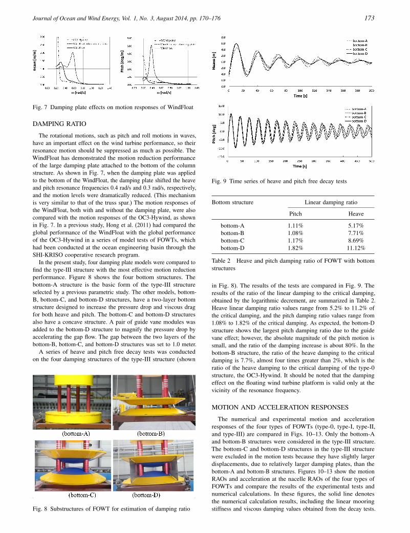
Fig. 7 Damping plate effects on motion responses of WindFloat
DAMPING RATIO
The rotational motions, such as pitch and roll motions in waves,have an important effect on the wind turbine performance, so theirresonance motion should be suppressed as much as possible. TheWindFloat has demonstrated the motion reduction performanceof the large damping plate attached to the bottom of the columnstructure. As shown in Fig. 7, when the damping plate was appliedto the bottom of the WindFloat, the damping plate shifted the heaveand pitch resonance frequencies 0.4 rad/s and 0.3 rad/s, respectively,and the motion levels were dramatically reduced. (This mechanismis very similar to that of the truss spar.) The motion responses ofthe WindFloat, both with and without the damping plate, were alsocompared with the motion responses of the OC3-Hywind, as shownin Fig. 7. In a previous study, Hong et al. (2011) had compared theglobal performance of the WindFloat with the global performanceof the OC3-Hywind in a series of model tests of FOWTs, whichhad been conducted at the ocean engineering basin through theSHI-KRISO cooperative research program.
In the present study, four damping plate models were compared tofind the type-III structure with the most effective motion reductionperformance. Figure 8 shows the four bottom structures. Thebottom-A structure is the basic form of the type-III structureselected by a previous parametric study. The other models, bottom-B, bottom-C, and bottom-D structures, have a two-layer bottomstructure designed to increase the pressure drop and viscous dragfor both heave and pitch. The bottom-C and bottom-D structuresalso have a concave structure. A pair of guide vane modules wasadded to the bottom-D structure to magnify the pressure drop byaccelerating the gap flow. The gap between the two layers of thebottom-B, bottom-C, and bottom-D structures was set to 1.0 meter.
A series of heave and pitch free decay tests was conductedon the four damping structures of the type-III structure (shown
Fig. 8 Substructures of FOWT for estimation of damping ratio
Fig. 9 Time series of heave and pitch free decay tests
Bottom structure Linear damping ratio
Pitch Heave
bottom-A 1.11% 5.17%bottom-B 1.08% 7.71%bottom-C 1.17% 8.69%bottom-D 1.82% 11.12%
Table 2 Heave and pitch damping ratio of FOWT with bottomstructures
in Fig. 8). The results of the tests are compared in Fig. 9. Theresults of the ratio of the linear damping to the critical damping,obtained by the logarithmic decrement, are summarized in Table 2.Heave linear damping ratio values range from 5.2% to 11.2% ofthe critical damping, and the pitch damping ratio values range from1.08% to 1.82% of the critical damping. As expected, the bottom-Dstructure shows the largest pitch damping ratio due to the guidevane effect; however, the absolute magnitude of the pitch motion issmall, and the ratio of the damping increase is about 80%. In thebottom-B structure, the ratio of the heave damping to the criticaldamping is 7.7%, almost four times greater than 2%, which is theratio of the heave damping to the critical damping of the type-0structure, the OC3-Hywind. It should be noted that the dampingeffect on the floating wind turbine platform is valid only at thevicinity of the resonance frequency.
MOTION AND ACCELERATION RESPONSES
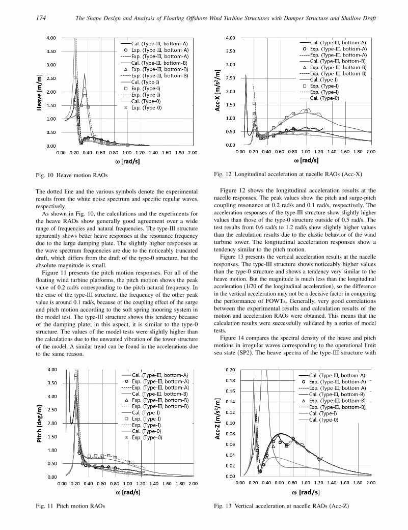
The numerical and experimental motion and accelerationresponses of the four types of FOWTs (type-0, type-I, type-II,and type-III) are compared in Figs. 10–13. Only the bottom-Aand bottom-B structures were considered in the type-III structure.The bottom-C and bottom-D structures in the type-III structurewere excluded in the motion tests because they have slightly largerdisplacements, due to relatively larger damping plates, than thebottom-A and bottom-B structures. Figures 10–13 show the motionRAOs and acceleration at the nacelle RAOs of the four types ofFOWTs and compare the results of the experimental tests andnumerical calculations. In these figures, the solid line denotesthe numerical calculation results, including the linear mooringstiffness and viscous damping values obtained from the decay tests.
174 The Shape Design and Analysis of Floating Offshore Wind Turbine Structures with Damper Structure and Shallow Draft
Fig. 10 Heave motion RAOs
The dotted line and the various symbols denote the experimentalresults from the white noise spectrum and specific regular waves,respectively.
As shown in Fig. 10, the calculations and the experiments forthe heave RAOs show generally good agreement over a widerange of frequencies and natural frequencies. The type-III structureapparently shows better heave responses at the resonance frequencydue to the large damping plate. The slightly higher responses atthe wave spectrum frequencies are due to the noticeably truncateddraft, which differs from the draft of the type-0 structure, but theabsolute magnitude is small.
Figure 11 presents the pitch motion responses. For all of thefloating wind turbine platforms, the pitch motion shows the peakvalue of 0.2 rad/s corresponding to the pitch natural frequency. Inthe case of the type-III structure, the frequency of the other peakvalue is around 0.1 rad/s, because of the coupling effect of the surgeand pitch motion according to the soft spring mooring system inthe model test. The type-III structure shows this tendency becauseof the damping plate; in this aspect, it is similar to the type-0structure. The values of the model tests were slightly higher thanthe calculations due to the unwanted vibration of the tower structureof the model. A similar trend can be found in the accelerations dueto the same reason.
Fig. 11 Pitch motion RAOs
Fig. 12 Longitudinal acceleration at nacelle RAOs (Acc-X)
Figure 12 shows the longitudinal acceleration results at thenacelle responses. The peak values show the pitch and surge-pitchcoupling resonance at 0.2 rad/s and 0.1 rad/s, respectively. Theacceleration responses of the type-III structure show slightly highervalues than those of the type-0 structure outside of 0.5 rad/s. Thetest results from 0.6 rad/s to 1.2 rad/s show slightly higher valuesthan the calculation results due to the elastic behavior of the windturbine tower. The longitudinal acceleration responses show atendency similar to the pitch motion.
Figure 13 presents the vertical acceleration results at the nacelleresponses. The type-III structure shows noticeably higher valuesthan the type-0 structure and shows a tendency very similar to theheave motion. But the magnitude is much less than the longitudinalacceleration (1/20 of the longitudinal acceleration), so the differencein the vertical acceleration may not be a decisive factor in comparingthe performance of FOWTs. Generally, very good correlationsbetween the experimental results and calculation results of themotion and acceleration RAOs were obtained. This means that thecalculation results were successfully validated by a series of modeltests.
Figure 14 compares the spectral density of the heave and pitchmotions in irregular waves corresponding to the operational limitsea state (SP2). The heave spectra of the type-III structure with
Fig. 13 Vertical acceleration at nacelle RAOs (Acc-Z)

Journal of Ocean and Wind Energy, Vol. 1, No. 3, August 2014, pp. 170–176 175
Fig. 14 Spectral density of heave and pitch motions in irregularwaves (SP2)
bottom-A and bottom-B structures show better performance thanthe heave spectra of the type-I structure, while the heave spectraof the type-0 structure show even better performance than theheave spectra of the type-III structure; however, the performance ofthe type-III structure seems acceptable since the absolute level isnegligible compared with the wave spectrum. The pitch spectra ofthe type-III structure show almost the same performance as thepitch spectra of the type-0 structure, as expected from the regularwave response, but the resonance peaks near the wave frequencyof 0.2 rad/s are slightly larger for the type-III structure due toits small draft. The motion spectra of the type-III structure withthe bottom-B structure, at the resonance frequency of around 0.2rad/s, show a slightly smaller value than the motion spectra ofthe bottom-A structure, due to the difference in the damping ratiovalues shown in Table 2.
Figures 15 and 16 compare the root mean square (RMS) valuesof the heave and pitch motions in operational (SP1) and operationallimit (SP2) irregular waves, respectively. The heave response of thetype-III structure shows values that are about 60% higher than thoseof the type-0 structure in the operational limit sea state, due to theshorter draft of the type-III structure, which is less than half of theOC3-Hywind’s draft; however, it should be noted that the absolutelevel of heave in an irregular sea state is very low—less than
Fig. 15 RMS values of heave motion in irregular waves
Fig. 16 RMS values of pitch motion in irregular waves
0.3 meters (the rms value) in conditions up to sea state 6, which isthe limit of the operational condition. On the other hand, the pitchresponses of the type-III structure are almost comparable to thoseof the type-0 structure. These results demonstrate a noticeableimprovement in performance when compared with the results ofthe type-I structure, which was the initial design concept.
Figures 17 and 18 compare the results of the accelerationresponses at the nacelle in irregular waves. The longitudinal andvertical acceleration responses present tendencies similar to theheave and pitch motions, respectively. In the case of the type-IIIstructure, the effect of the bottom structural change is negligiblein spite of the heave and pitch damping differences, because theresonance response is not significant in the present irregular wave
Fig. 17 RMS values of longitudinal acceleration at nacelle (Acc-X)

176 The Shape Design and Analysis of Floating Offshore Wind Turbine Structures with Damper Structure and Shallow Draft
Fig. 18 RMS values of vertical acceleration at nacelle (Acc-Z)
conditions. The results of the motion and acceleration responses inirregular waves for the model tests and the numerical calculationsshow good agreement.
CONCLUSIONS
A series of parametric studies for several shape designs of 5MWclass FOWTs was conducted in order to apply FOWTs in waterdepth less than 100 m, where fixed structures are not economicallyfeasible. The design concept was to have a shorter draft thanthe typical spar design so as to have cost-effective constructionand installation. Through the parametric studies conducted bynumerical analysis using the 9-node higher-order boundary elementmethod (HOBEM), an optimum wind turbine platform for usein relatively shallow water was designed. This platform has thetruss spar shape with a damper structure to reduce the motionand acceleration responses, as well as a shallow draft that is lessthan half of the OC3-Hywind’s draft. The pitch and longitudinalacceleration responses of the offshore wind turbine platform showeda generally satisfactory operational performance comparable withthe operational performance of the OC3-Hywind.
To verify the numerical simulation and validate the comparativestudy of FOWTs, a series of model tests was performed at theKRISO ocean engineering basin. Regular and irregular wave testsdemonstrated the usefulness of the HOBEM-devised parametricdesign of FOWTs, which showed good correlation with the modeltests.
For the safe and effective design of FOWTs, a comprehensiveevaluation of an integrated solution considering the aero-hydro-servo-elastic effect of FOWTs will be investigated in the future.
ACKNOWLEDGEMENTS
The authors wish to thank the Korea Research Council ofFundamental Science and Technology for their support of the“SHI-KRISO Cooperative Research Program for Enhancementof Offshore Structure Design Technology,” the “Study on SparPlatform Technology for Multiple Deployment,” and the presentwork.
REFERENCES
Choi, YR, and Hong, SY (2002). “An Analysis of HydrodynamicInteraction of Floating Multi-body Using Higher-Order BoundaryElement Method,” Proc 12th Int Offshore Polar Eng Conf,Kitakyushu, Japan, ISOPE, 3, 303–308.
Hanson, TD, Skaare, B, Yttervik, R, Nielsen, FG, and Havmoller, O(2011). “Comparison of Measured and Simulated Responses atthe First Full Scale Floating Wind Turbine Hywind,” Presentedat EWEA 2011, Brussels, Belgium, European Wind EnergyAssociation.
Hong, SY, Kim, JH, Cho, SK, and Kim, YS (2005). “Numerical andExperimental Study on Hydrodynamic Interaction of Side-by-sideMoored Multiple Vessels,” Ocean Eng, 32, 783–801.
Hong, SY, Kim, JH, Kim, YS, and Kim, HJ (2011). SHI-KRISOCooperative Research Program for Enhancement of OffshoreStructure Design Technology, Korea Research Institute of Shipsand Ocean Engineering, Internal Report (in Korean).
Hong, SY, Kim, JH, Hong, SW, and Kim, HJ (2012a). “Design andAnalysis of a Box Floater with Damping Plates for FloatingWind Turbine Platform,” Proc 22nd Int Offshore Polar Eng Conf,Rhodes, Greece, ISOPE, 1, 411–416.
Hong, SY, Kim, JH, and Kim, HJ (2012b). “Design and Analysis ofa Box-type Floating Wind Turbine Structure with Large MotionDamping Plates,” Proc 10th Pacific/Asia Offshore Mech Symp(PACOMS), Vladivostock, Russia, ISOPE, 11–15.
Jonkman, J (2010). Definition of the Floating System for PhaseIV of OC3, Technical Report NREL/TP-500-47535, NationalRenewable Energy Laboratory, Golden, CO, USA.
Koo, BJ, Goupee, AJ, Lambrakos, K, and Kimall, RW (2012).“Model Tests for a Floating Wind Turbine on Three DifferentFloaters,” Proc 31st Int Conf Ocean Offshore Arct Eng, Rio deJaneiro, Brazil, ASME, 455–465.
Martin, HR, Kimall, RW, Viselli, AM, and Goupee, AJ (2012).“Methodology for Wind/Wave Basin Testing of Floating WindTurbines,” Proc 31st Int Conf Ocean Offshore Arct Eng, Rio deJaneiro, Brazil, ASME, 445–454.
Myhr, A, Maus, KJ, and Nygaard, TA (2011). “Experimental andComputational Comparison of the OC3-HYWIND and Tension-Leg-Buoy (TLB) Floating Wind Turbine Conceptual Design,”Proc 21st Int Offshore Polar Eng Conf, Maui, HI, USA, ISOPE,1, 353–360.
Nam, BW, et al. (2014). “Performance Evaluation of the FloatingPendulum Wave Energy Converter in Regular and IrregularWaves,” Int J Offshore Polar Eng, 24(1), 45–51.
Robertson, AN, and Jonkman, M (2011). “Loads Analysis ofSeveral Offshore Floating Wind Turbine Concepts,” Proc 21st IntOffshore Polar Eng Conf, Maui, HI, USA, ISOPE, 1, 443–450.
Roddier, D, Cemelli, C, Aubault, A, and Weinstein, A (2010).“WindFloat: A Floating Foundation for Offshore Wind Turbines,”J Renewable Sustainable Energy, 2(3), doi: 10.1063/1.3435339.
van Steen, H (2012). “Global Offshore Wind–the EU Perspec-tive,” Presented at Global Offshore Wind Conf, Renewable UK,London, UK.