the st. john’s wood square project · st john’s wood square project and should be read in...
TRANSCRIPT
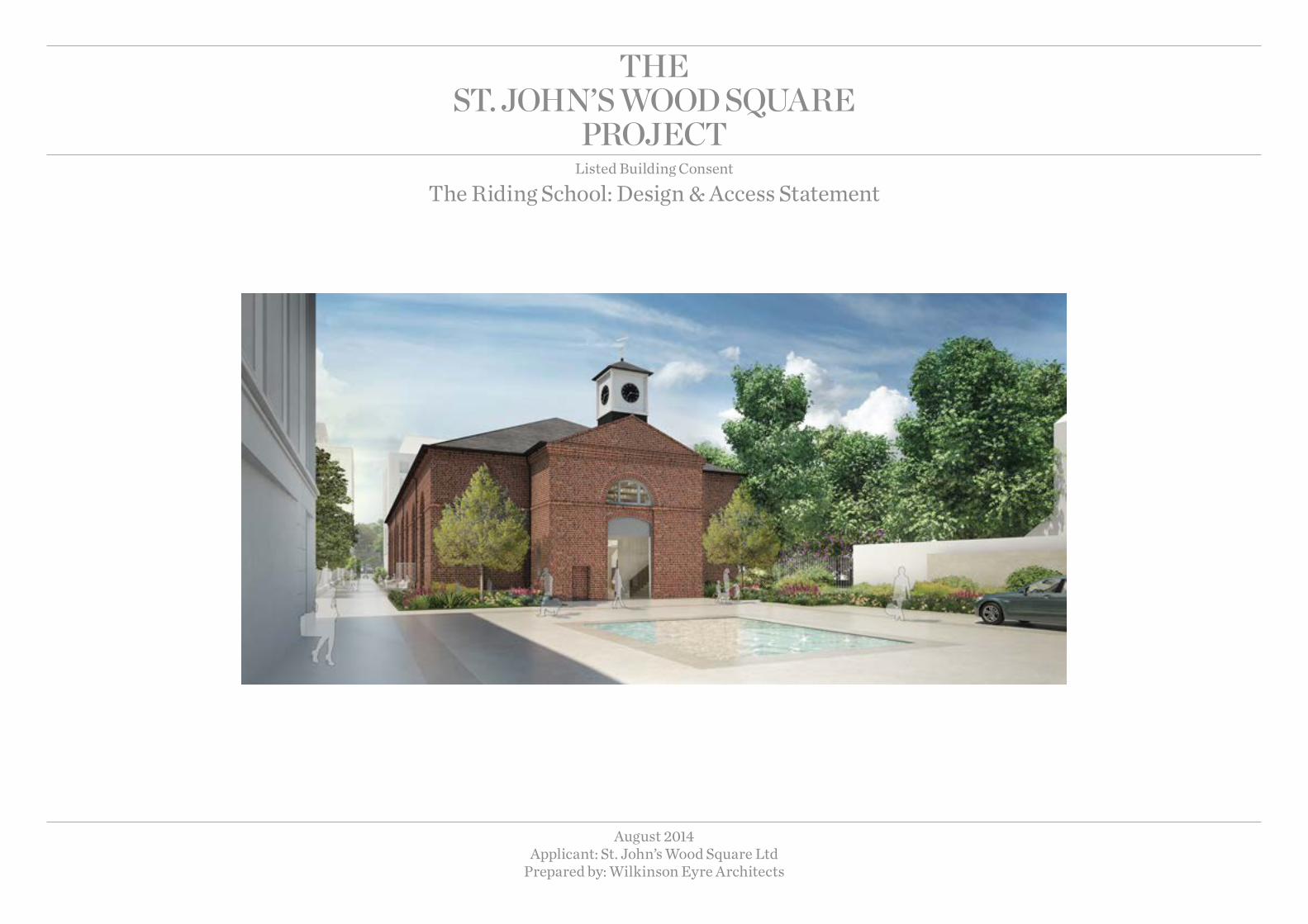
The sT. john’s wood square
projecTListed Building Consent
The Riding School: Design & Access Statement
August 2014 Applicant: St. John’s Wood Square Ltd
Prepared by: Wilkinson Eyre Architects
Report Title: Design and Access Statement
Job Name: Riding School
Reason For Issue: Information
Prepared by: Approved by:
Name: Laura Rigoni Name: Jim Eyre
Senior Architect Director
Rev No Comments Date
A Issued for Planning August 2014
Job No: 987
File Reference: R19
Date Created: 20.06.2014

1 Preface 5
2 Introduction 7
2.1 Background 7
2.2 Objectives 8
2.3 Functional Brief 9
3 Site analysis 11
3.1 Site historical development 11
3.2 Existing Site and Buildings 21
3.3 The Riding School and relationship to the proposed main development 25
3.4 Consented Scheme 26
4 Architectural design proposal 29
4.1 Detailed Development of the Functional Brief 29
4.2 Building layout 30
4.3 Consultations 40
5 Material and fabrics 43
5.1 Proposed Alterations to Existing Building Fabric 43
5.3 Interior fabric proposal 54
5.4 Materiality 57
6 Heritage impact assessment 59
7 Public realm and landscape 63
8 Sustainability, Energy strategy and Building Services 65
8.1 Sustainability Implementation Plan (SIP) 65
8.4 Materials 66
8.5 Waste 66
8.6 Pollution 66
8.7 Health & Well-being 66
8.8 Management 66
8.9 Ecology & Land Use 67
8.10 Transport 67
8.11 Energy Hierarchy
8.12 Passive Design Measures 67
8.13 EnergyEfficientSystems 67
8.14 Low & Zero Carbon Technologies 69
9 Access Statement 71
9.1 Statutory and regulatory background 71
9.2 Design philosophy 72
9.3 Riding School Spa and Pool 72
10 Enabling works proposals 75
10.0 Introduction 75
10.1 Scope of Works 75
Contents

Wilkinson Eyre Architects Riding School4
Project Team
APPLICANT
St John’s Wood Square Limited
La Motte Chambers St Helier Jersey JE1 1PB
DEVELOPMENT MANAGER
Craigewan Consulting Limited
2-4 King StreetLondonSW1Y 6QL
TOWN PLANNINGDP9100 Pall Mall London SW1Y 5NQ
STRUCTURES AND CIVIL
Robert Bird
Harling House Level 2 47 – 51 Great Suffolk Street London SE1 0BS
BUILDING CONTROL
MLM
Building control 2-3 Eldon Street London EC2M 7LS
TOWNSCAPE / HERITAGE CONSULTANT
Richard Coleman Citydesigner
14 Lower Grosvenor Place London SW1W 0EX
M&E / SUSTAINABILITY
Atelier Ten19 Perseverance Works 38 Kingsland Road London E2 8DD
ACOUSTIC ENGINEER
Sandy Brown55 Charterhouse Street London EC1M 6HA
RIDING SCHOOL ARCHITECT
Wilkinson Eyre Architects
33 Bowling Green Lane London EC1R 0BJ
PROJECT MANAGEMENT
EC Harris34 York Way London N1 9AB
ESTATE MANAGEMENT
Qube
136 Pinner Road Northwood Middlesex HA6 1BP
POOL CONSULTANT
Devin Consulting
85 Howard Street North Shields Newcastle upon Tyne NE30 1AF
TRAffIC AND TRANSPORT
WYG Environment Planning Transport Ltd100 St John Street London EC1M 4EH
CDM COORDINATORRLF
Marylebone House
52-54 St John Street London EC1M 4HF
EXECUTIVE ARCHITECT
Squire and Partners
77 Wicklow Street London WC1X 9JY
COST MANAGEMENT
EC Harris
34 York Way London N1 9AB
fIRE STRATEGY
EXOVA Warrington Fire
65-71 Bermondsey Street London SE1 3XF
ACCESSIBILITY CONSULTANT
Earnscliffe
64 Havelock Road Brighton BN1 6GF
LEGAL
Taylor Wessing
5 New Street Square London EC4A 3TW Tel: 0207 300 7000
Riding School Wilkinson Eyre Architects 5
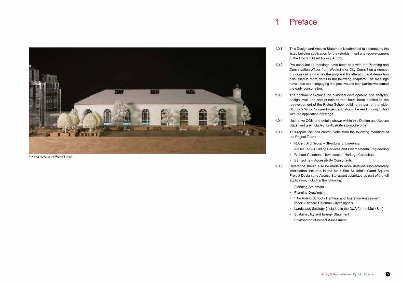
1 Preface
1.0.1 This Design and Access Statement is submitted to accompany the listed building application for the refurbishment and redevelopment of the Grade II listed Riding School.
1.0.2 Pre-consultation meetings have been held with the Planning and ConservationofficerfromWestminsterCityCouncilonanumberof occasions to discuss the proposal for alteration and demolition discussed in more detail in the following chapters. The meetings have been open, engaging and positive and both parties welcomed the early consultation.
1.0.3 The document explains the historical development, site analysis, design evolution and principles that have been applied to the redevelopment of the Riding School building as part of the wider St John’s Wood Square Project and should be read in conjunction with the application drawings.
1.0.4 Illustrative CGIs and details shown within this Design and Access Statement are included for illustrative purpose only.
1.0.5 This report includes contributions from the following members of the Project Team:
• Robert Bird Group – Structural Engineering
• Atelier Ten – Building Services and Environmental Engineering
• Richard Coleman – Townscape / Heritage Consultant
• Earnscliffe – Accessibility Consultants
1.0.6 Reference should also be made to more detailed supplementary information included in the Main Site St John’s Wood Square Project Design and Access Statement submitted as part of the full application, including the following:
• Planning Statement
• Planning Drawings
• ‘The Riding School - Heritage and Alteration Assessment’ report (Richard Coleman Citydesigner)
• Landscape Strategy (included in the D&A for the Main Site)
• Sustainability and Energy Statement
• Environmental Impact Assessment
Physical model of the Riding School
Wilkinson Eyre Architects Riding School6
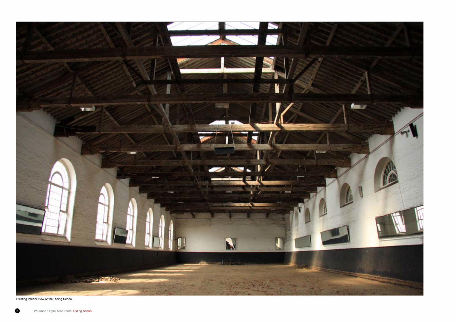
Existing interior view of the Riding School

Riding School Wilkinson Eyre Architects 7
2.1 Background2.1.1 TheSitebenefits fromanumberofextantconsentswhichwere
granted permission in May 2011. Together they comprise ‘the Consented Scheme’. These can be summarised as follows:
• Full Planning Permission (08/10114/FULL) for the provision of 133 residential units based around an urban pattern of terraces and townhouses, arranged around east-west landscaped streets through the site, with the creation of an ancillary leisure facility within the Grade II listed Riding School, the creation of ancillary car parking at basement and ground, and the creation of landscaped areas;
• Conservation Area Consent (08/10116/CAC) for the demolition of all existing buildings with the exception of the Riding School; and
• Listed Building Consent (08/10115/LBC) for internal and external works to the Riding School to create a private leisure facility ancillary to the residential use.
2.1.2 The Applicant acquired the Site in April 2012. Following a review of the Consented Scheme, it was decided to pursue a revised masterplan for theSite, reflecting theApplicant’s vision for theSite as a family orientated environment that enhances the unique characteristics of the locality. Whilst the Consented Scheme has not been implemented, it has established the acceptability of the demolition of the existing buildings at the Site (with the exception of the listed Riding School), as well as the acceptability of residential use on the Site. This is a material planning consideration which has informed the development of the Proposed Development and is relevant to the determination of this application. In terms of the Riding School, this element of the Proposed Development has been specificallyrevisitedtoprovideanenhancedsettingadjacenttothenew garden square. The Consented Scheme secured a Pedestrian Access Way through the Site which ran between Ordnance Hill and Queen’s Terrace. The nature of the route was secured as part of the Section 106 agreement, with the same arrangements secured as part of this planning application. The Proposed Development retains a Pedestrian Access Way across the Site but in an alternative location which takes pedestrians past the listed Riding School and Garden Square, and links the Proposed Development to the Queen’s Terrace retail shops. This offers the wider community the opportunity to pass the Riding School when using the Pedestrian Access Way which is an enhancement when compared to the Consented Scheme.
2 Introduction
Aerial view of the St John’s Wood Barracks Site
Key SJWS Site boundary Grade II listed Riding School Building
Wilkinson Eyre Architects Riding School8
2 Introduction
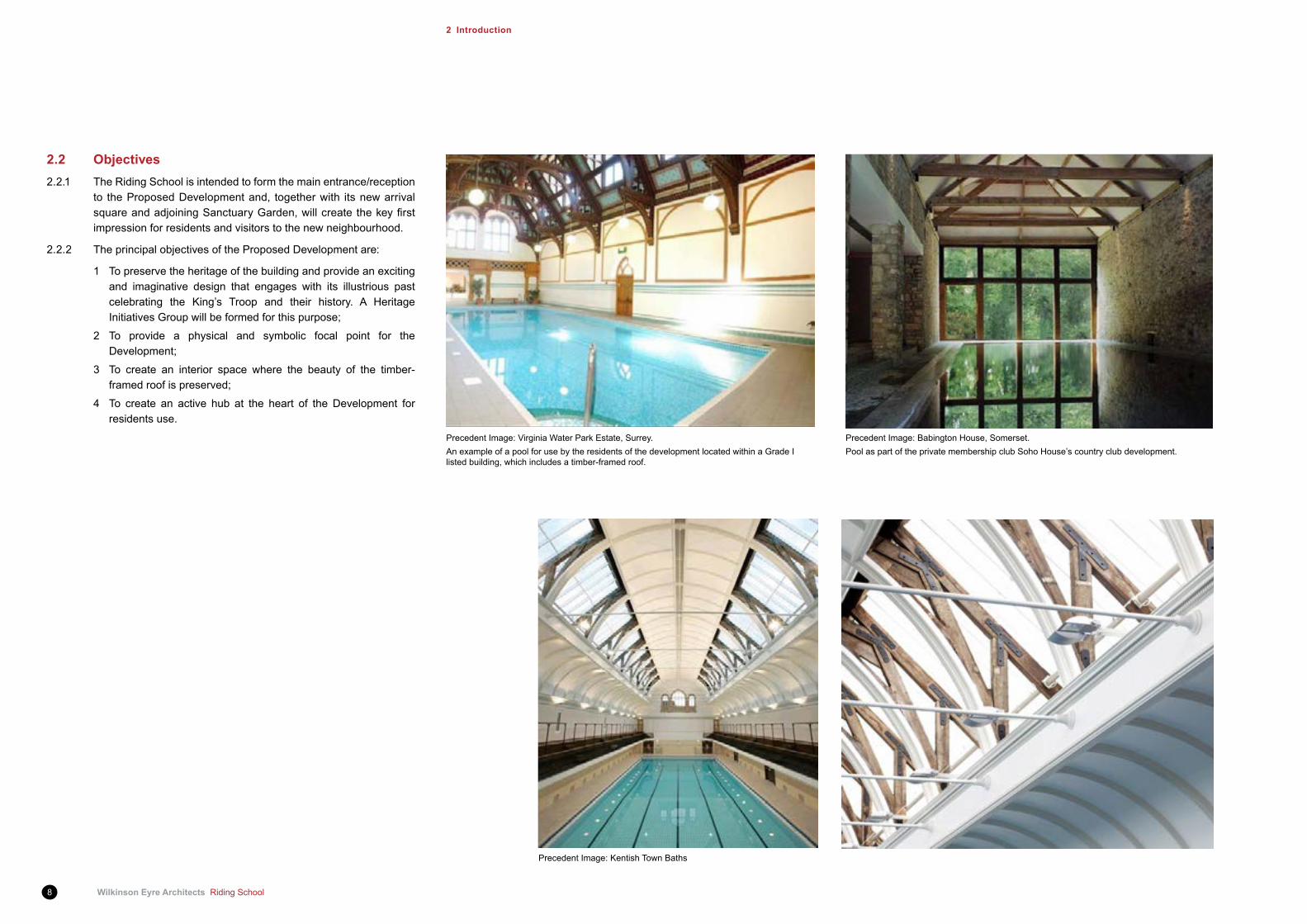
Precedent Image: Kentish Town Baths
Precedent Image: Virginia Water Park Estate, Surrey.An example of a pool for use by the residents of the development located within a Grade I listed building, which includes a timber-framed roof.
Precedent Image: Babington House, Somerset.Pool as part of the private membership club Soho House’s country club development.
2.2 Objectives2.2.1 The Riding School is intended to form the main entrance/reception
to the Proposed Development and, together with its new arrival squareandadjoiningSanctuaryGarden,willcreatethekeyfirstimpression for residents and visitors to the new neighbourhood.
2.2.2 The principal objectives of the Proposed Development are:
1 To preserve the heritage of the building and provide an exciting and imaginative design that engages with its illustrious past celebrating the King’s Troop and their history. A Heritage Initiatives Group will be formed for this purpose;
2 To provide a physical and symbolic focal point for the Development;
3 To create an interior space where the beauty of the timber-framed roof is preserved;
4 To create an active hub at the heart of the Development for residents use.
Riding School Wilkinson Eyre Architects 9
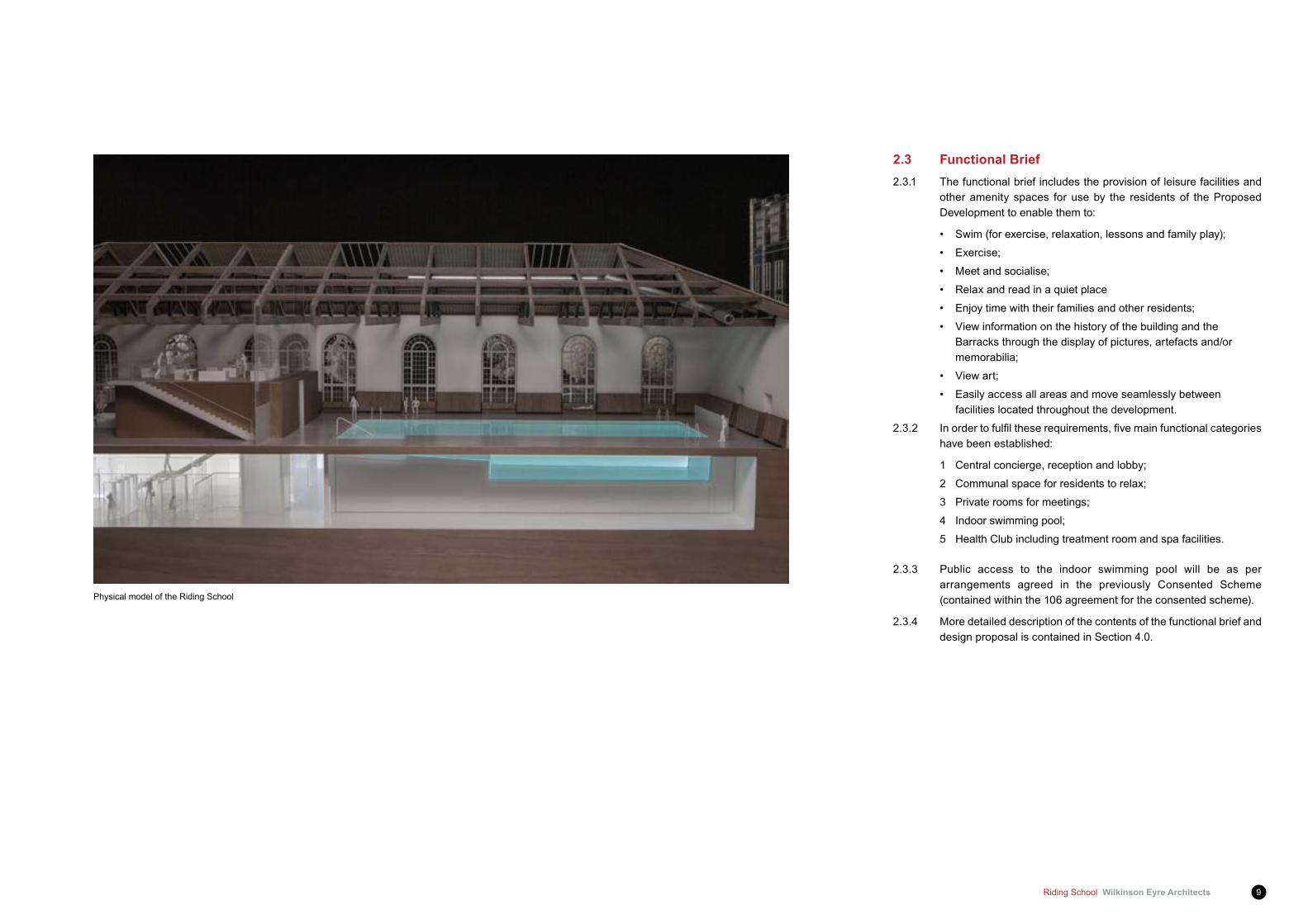
2.3 functional Brief2.3.1 The functional brief includes the provision of leisure facilities and
other amenity spaces for use by the residents of the Proposed Development to enable them to:
• Swim (for exercise, relaxation, lessons and family play);
• Exercise;
• Meet and socialise;
• Relax and read in a quiet place
• Enjoy time with their families and other residents;
• View information on the history of the building and the Barracks through the display of pictures, artefacts and/or memorabilia;
• View art;
• Easily access all areas and move seamlessly between facilities located throughout the development.
2.3.2 Inordertofulfiltheserequirements,fivemainfunctionalcategorieshave been established:
1 Central concierge, reception and lobby;
2 Communal space for residents to relax;
3 Private rooms for meetings;
4 Indoor swimming pool;
5 Health Club including treatment room and spa facilities.
2.3.3 Public access to the indoor swimming pool will be as per arrangements agreed in the previously Consented Scheme (contained within the 106 agreement for the consented scheme).
2.3.4 More detailed description of the contents of the functional brief and design proposal is contained in Section 4.0.
Physical model of the Riding School
Wilkinson Eyre Architects Riding School10
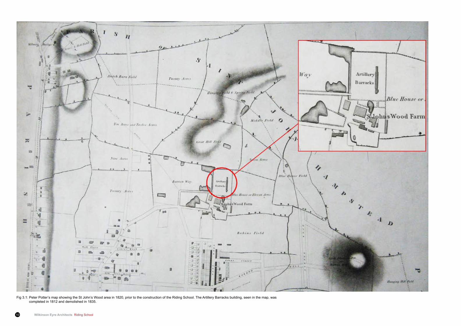
Fig 3.1: Peter Potter’s map showing the St John’s Wood area in 1820, prior to the construction of the Riding School. The Artillery Barracks building, seen in the map, was completed in 1812 and demolished in 1835.
Riding School Wilkinson Eyre Architects 11
3 Site analysis
3.1 Site historical development3.1.1 This chapter is an extract from Richard Coleman Citydesigner’s
‘The Riding School - Heritage and Alteration Assessment’ report and provides an overview of the general history of the Main Site and the Riding School.
3.1.2 The study draws from ‘The Wood – A Short History of the Barracks at St John’s Wood’ by Lieutenant JCC Sworder RHA, 1959; the ‘Cottages and Villas: the Birth of the Garden Suburb’ by Mireille Galinou, 2010; the ‘Guns at the Wood’ by Joan Wanklyn, 1972; extracts from architectural journals; records from the National Archives; and a series of historic maps. The red outline on each map shows the approximate extent of the St. John’s Wood Barracks site.
3.1.3 The area, including where the Main Site is today, was acquired by the wine merchant Henry Samuel Eyre in 1732 but remained asagriculturalholdings,dividedintosmallfields,until theendofthe 18th century. St John’s Wood Farm lay 0.2 miles south-west from where the Main Site is today. As early as 1804, the tenant farmer at St John ’s Wood Farm offered a barn as accommodation to a Cavalry Unit, on Eyre Estate land adjacent to his farm. At that time it was uncommon for soldiers to be provided with purpose built, permanent accommodation. The quarters at the farm and the location in St John’s Wood suited the cavalry because of the surroundingopenfieldsandeasydistancetotheCapital.Around1810, about four acres of land immediately north of the farm were leased to the Board of Ordnance from the Eyre family. The name Ordnance Hill derives from this early military settlement. On this site, the Board built a two-storey barrack block, running north to south, designated as ‘New Artillery Barracks’ and completed in 1812. The building was demolished in 1835 and replaced by a new block built with London stock brick and running west to east, parallel with the present Acacia Road.
3.1.4 A 99 year lease was obtained for the St John’s Wood Barracks site commencing in 1820 and a Riding School built in 1825. Though the listing citation states its completion as 1823-4, a brass plate which decorated the Riding School, but which is lost today, stated that the Riding School was completed in March 1825, superintended by Brevet Major Tylden of the Royal Engineers and measured 184’6” in length. A description of the building by Joan Wanklyn states “Though severely practical and unadorned, the building is well proportioned and has a certain austere dignity not unpleasing to modern eyes. Its most attractive external features are the eight tall, round-arched windows on the southern side. On the north there are an equal number of arches, glazed only at the top, and at the eastern end a gallery for spectators is reached by a staircase inside a porch or vestibule. In their original state, the exterior walls were brown London stock brick, topped with a grey slated roof (...) Originally there was no clock tower – this was a Victorian addition (...) Inside, the vista of massive queen-post trusses with their shaped timber corbels and iron reinforcing hoops was reminiscent of a gigantic tithe barn”. At the time, temporary sheds would have been used for the accommodation of the horses, while wooden cottages were built for married soldiers. By 1832 the Cavalry Unit was moved to Maidstone. The complex was adapted for use by the Foot Guards who were billeted there and further barracks were built by 1835.
3.1.5 After being a cavalry riding establishment since 1825, the Riding School was adapted for use by the Foot Guards from 1832 to 1876. Around this time, half of the interior of the building was developed into stores. This was achieved by erecting internal structures and blocking off a portion of its length (see figures 3.25–3.28). Anarticle in Country Life dated July 1971 states that the school was modifiedsothathalfwasavailablefordrillorgymnastics,andtheotherhalf,withtheinclusionofadditionalfloors,wasadaptedashospital, stores and accommodation for soldiers. More recently this modifiedendhashousedharnessrooms,saddlers’andgunfitters’workshop, in addition to stores. Beams and hooks have been found in the building resembling ones used for the attachment of climbing ropes.
Wilkinson Eyre Architects Riding School12
3 Site Analysis
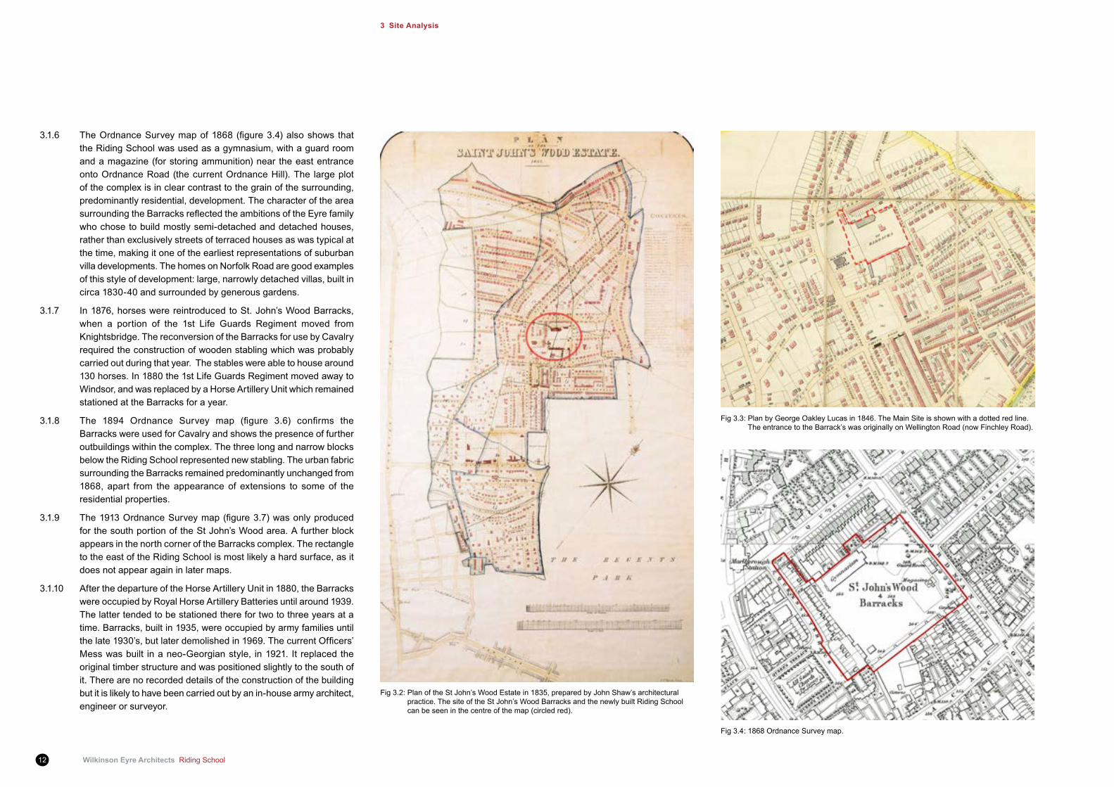
3.1.6 TheOrdnanceSurveymapof1868(figure3.4)alsoshows thatthe Riding School was used as a gymnasium, with a guard room and a magazine (for storing ammunition) near the east entrance onto Ordnance Road (the current Ordnance Hill). The large plot of the complex is in clear contrast to the grain of the surrounding, predominantly residential, development. The character of the area surroundingtheBarracksreflectedtheambitionsoftheEyrefamilywho chose to build mostly semi-detached and detached houses, rather than exclusively streets of terraced houses as was typical at the time, making it one of the earliest representations of suburban villa developments. The homes on Norfolk Road are good examples of this style of development: large, narrowly detached villas, built in circa 1830-40 and surrounded by generous gardens.
3.1.7 In 1876, horses were reintroduced to St. John’s Wood Barracks, when a portion of the 1st Life Guards Regiment moved from Knightsbridge. The reconversion of the Barracks for use by Cavalry required the construction of wooden stabling which was probably carried out during that year. The stables were able to house around 130 horses. In 1880 the 1st Life Guards Regiment moved away to Windsor, and was replaced by a Horse Artillery Unit which remained stationed at the Barracks for a year.
3.1.8 The 1894 Ordnance Survey map (figure 3.6) confirms theBarracks were used for Cavalry and shows the presence of further outbuildings within the complex. The three long and narrow blocks below the Riding School represented new stabling. The urban fabric surrounding the Barracks remained predominantly unchanged from 1868, apart from the appearance of extensions to some of the residential properties.
3.1.9 The1913OrdnanceSurveymap(figure3.7)wasonlyproducedfor the south portion of the St John’s Wood area. A further block appears in the north corner of the Barracks complex. The rectangle to the east of the Riding School is most likely a hard surface, as it does not appear again in later maps.
3.1.10 After the departure of the Horse Artillery Unit in 1880, the Barracks were occupied by Royal Horse Artillery Batteries until around 1939. The latter tended to be stationed there for two to three years at a time. Barracks, built in 1935, were occupied by army families until thelate1930’s,butlaterdemolishedin1969.ThecurrentOfficers’Mess was built in a neo-Georgian style, in 1921. It replaced the original timber structure and was positioned slightly to the south of it. There are no recorded details of the construction of the building but it is likely to have been carried out by an in-house army architect, engineer or surveyor.
Fig 3.2: Plan of the St John’s Wood Estate in 1835, prepared by John Shaw’s architectural practice. The site of the St John’s Wood Barracks and the newly built Riding School can be seen in the centre of the map (circled red).
Fig 3.3: Plan by George Oakley Lucas in 1846. The Main Site is shown with a dotted red line. The entrance to the Barrack’s was originally on Wellington Road (now Finchley Road).
Fig 3.4: 1868 Ordnance Survey map.
Riding School Wilkinson Eyre Architects 13
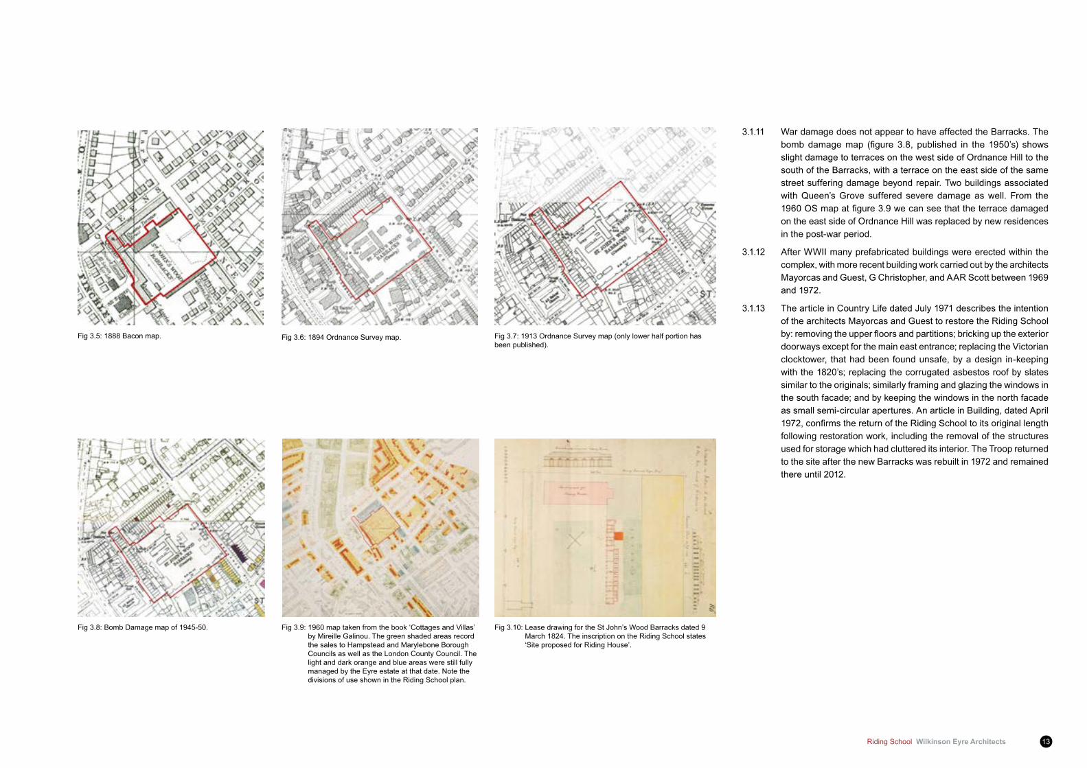
3.1.11 War damage does not appear to have affected the Barracks. The bombdamagemap (figure 3.8, published in the 1950’s) showsslight damage to terraces on the west side of Ordnance Hill to the south of the Barracks, with a terrace on the east side of the same street suffering damage beyond repair. Two buildings associated with Queen’s Grove suffered severe damage as well. From the 1960OSmapatfigure3.9wecanseethattheterracedamagedon the east side of Ordnance Hill was replaced by new residences in the post-war period.
3.1.12 After WWII many prefabricated buildings were erected within the complex, with more recent building work carried out by the architects Mayorcas and Guest, G Christopher, and AAR Scott between 1969 and 1972.
3.1.13 The article in Country Life dated July 1971 describes the intention of the architects Mayorcas and Guest to restore the Riding School by:removingtheupperfloorsandpartitions;brickinguptheexteriordoorways except for the main east entrance; replacing the Victorian clocktower, that had been found unsafe, by a design in-keeping with the 1820’s; replacing the corrugated asbestos roof by slates similar to the originals; similarly framing and glazing the windows in the south facade; and by keeping the windows in the north facade as small semi-circular apertures. An article in Building, dated April 1972,confirmsthereturnoftheRidingSchooltoitsoriginallengthfollowing restoration work, including the removal of the structures used for storage which had cluttered its interior. The Troop returned to the site after the new Barracks was rebuilt in 1972 and remained there until 2012.
Fig 3.5: 1888 Bacon map. Fig 3.6: 1894 Ordnance Survey map. Fig 3.7: 1913 Ordnance Survey map (only lower half portion has been published).
Fig 3.8: Bomb Damage map of 1945-50. Fig 3.9: 1960 map taken from the book ‘Cottages and Villas’ by Mireille Galinou. The green shaded areas record the sales to Hampstead and Marylebone Borough Councils as well as the London County Council. The light and dark orange and blue areas were still fully managed by the Eyre estate at that date. Note the divisions of use shown in the Riding School plan.
Fig 3.10: Lease drawing for the St John’s Wood Barracks dated 9 March 1824. The inscription on the Riding School states ‘Site proposed for Riding House’.
Wilkinson Eyre Architects Riding School14
3 Site Analysis
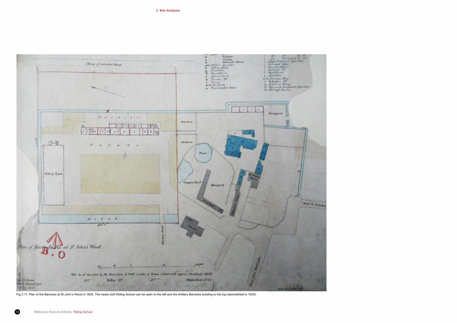
Fig 3.11: Plan of the Barracks at St John’s Wood in 1825. The newly built Riding School can be seen to the left and the Artillery Barracks building to the top (demolished in 1835).
Riding School Wilkinson Eyre Architects 15
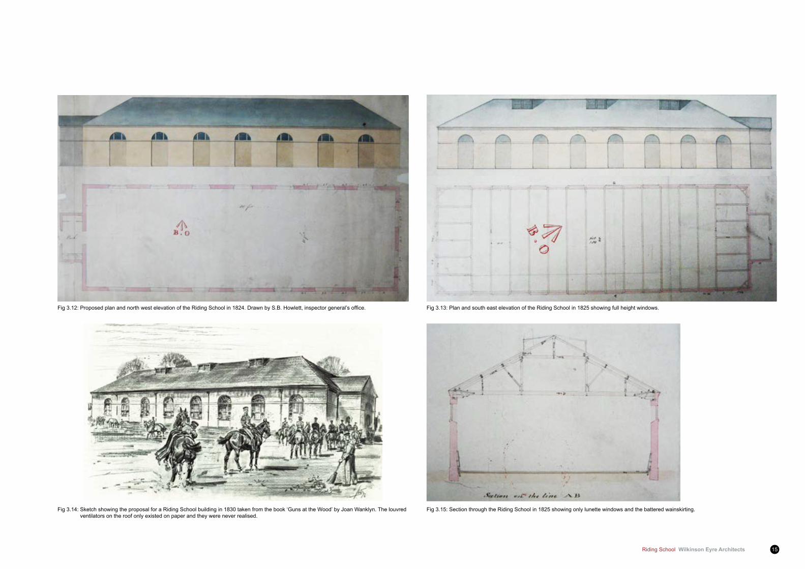
Fig 3.14: Sketch showing the proposal for a Riding School building in 1830 taken from the book ‘Guns at the Wood’ by Joan Wanklyn. The louvred ventilators on the roof only existed on paper and they were never realised.
Fig 3.15: Section through the Riding School in 1825 showing only lunette windows and the battered wainskirting.
Fig3.12:ProposedplanandnorthwestelevationoftheRidingSchoolin1824.DrawnbyS.B.Howlett,inspectorgeneral’soffice. Fig 3.13: Plan and south east elevation of the Riding School in 1825 showing full height windows.
Wilkinson Eyre Architects Riding School16
3 Site Analysis
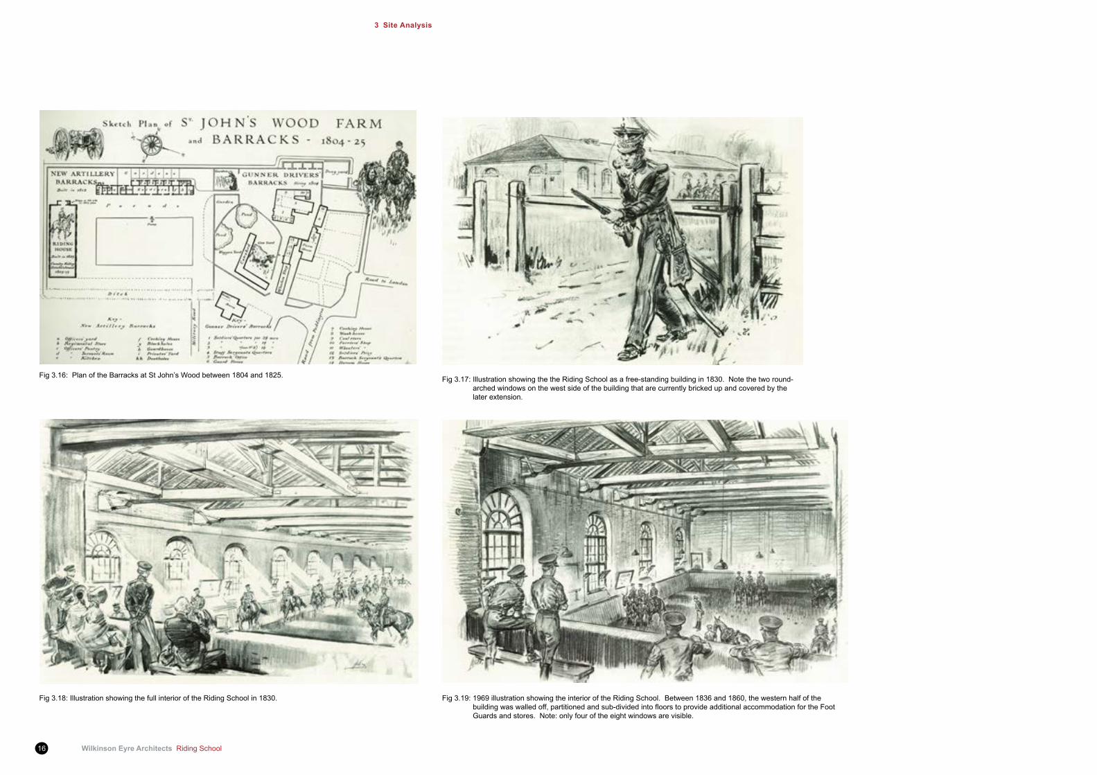
Fig 3.18: Illustration showing the full interior of the Riding School in 1830.
Fig 3.16: Plan of the Barracks at St John’s Wood between 1804 and 1825.
Fig 3.19: 1969 illustration showing the interior of the Riding School. Between 1836 and 1860, the western half of the buildingwaswalledoff,partitionedandsub-dividedintofloorstoprovideadditionalaccommodationfortheFootGuards and stores. Note: only four of the eight windows are visible.
Fig 3.17: Illustration showing the the Riding School as a free-standing building in 1830. Note the two round-arched windows on the west side of the building that are currently bricked up and covered by the later extension.

Riding School Wilkinson Eyre Architects 17
Fig3.20:PlanshowingtheproposedconversionoftheRidingSchoolintoagymnasium,divisionofspaceandinsertionoffireplaces/chimneysin1861, drawnbytheRoyalEngineerOffice.
Fig 3.21: Section through the entrance porch and window detail, 1861.
Fig 3.22: Section through the Riding School showing its proposed conversion into a gymnasium in 1861. Fig 3.23: Riding school windows details, 1861. Fig 3.24: Riding school, section through chimney, 1861.
Wilkinson Eyre Architects Riding School18
3 Site Analysis
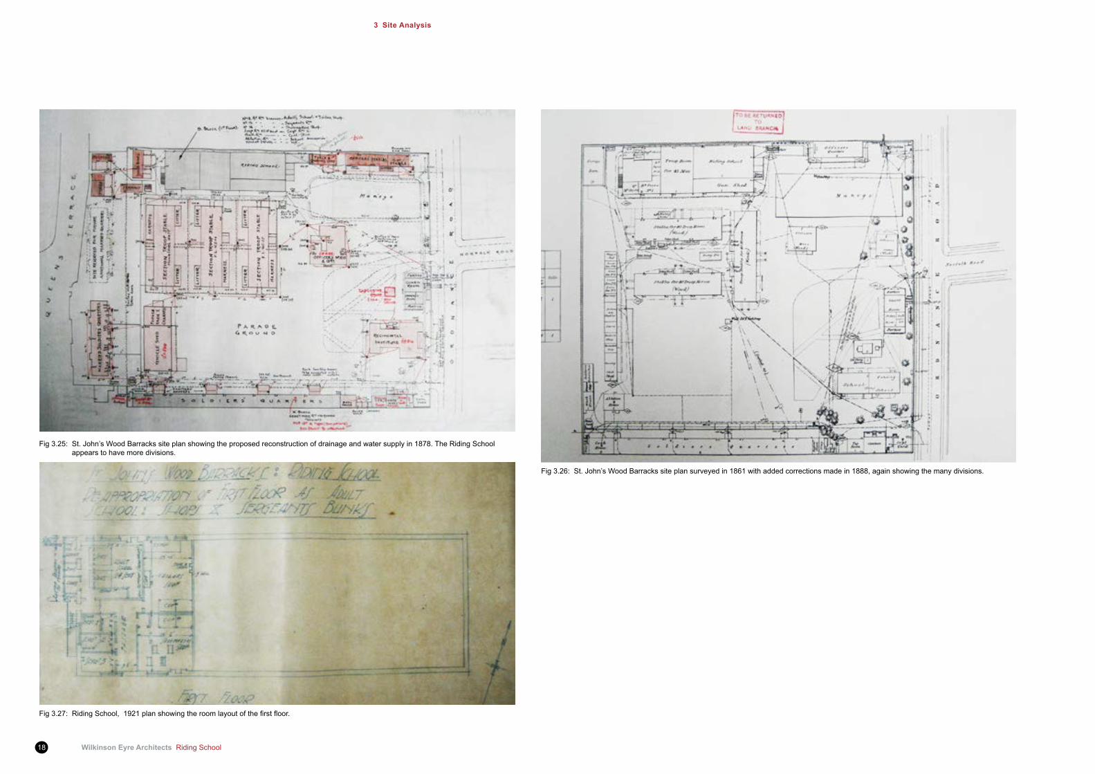
Fig 3.25: St. John’s Wood Barracks site plan showing the proposed reconstruction of drainage and water supply in 1878. The Riding School appears to have more divisions.
Fig 3.26: St. John’s Wood Barracks site plan surveyed in 1861 with added corrections made in 1888, again showing the many divisions.
Fig3.27:RidingSchool,1921planshowingtheroomlayoutofthefirstfloor.

Riding School Wilkinson Eyre Architects 19
Fig 3.28: Plan of St John’s Wood Barracks in 1969, taken from the book ‘Guns at the Wood’ by Joan Wanklyn. Fig 3.30: View of St John’s Wood Barracks in 1950’s. The Riding School’s original clock-tower can be seen to the left.
Fig 3.29: Photograph showing the troop formed up on the square at St John’s Wood Barracks forthefirstpost-warRoyalSalute,June1946.TheRidingSchoolisclearlybrickfaced.
Wilkinson Eyre Architects Riding School20
3 Site Analysis
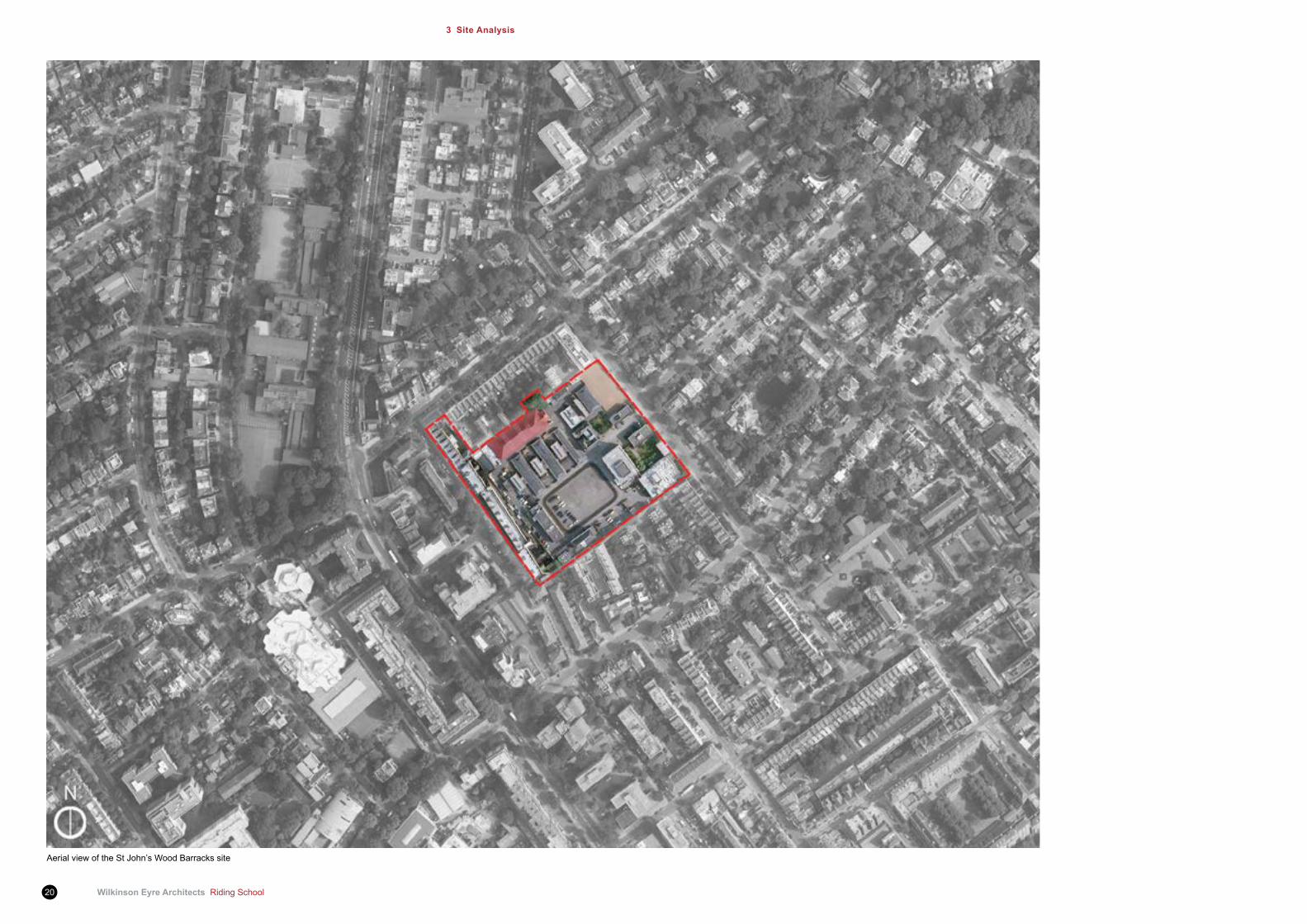
Aerial view of the St John’s Wood Barracks site
Riding School Wilkinson Eyre Architects 21
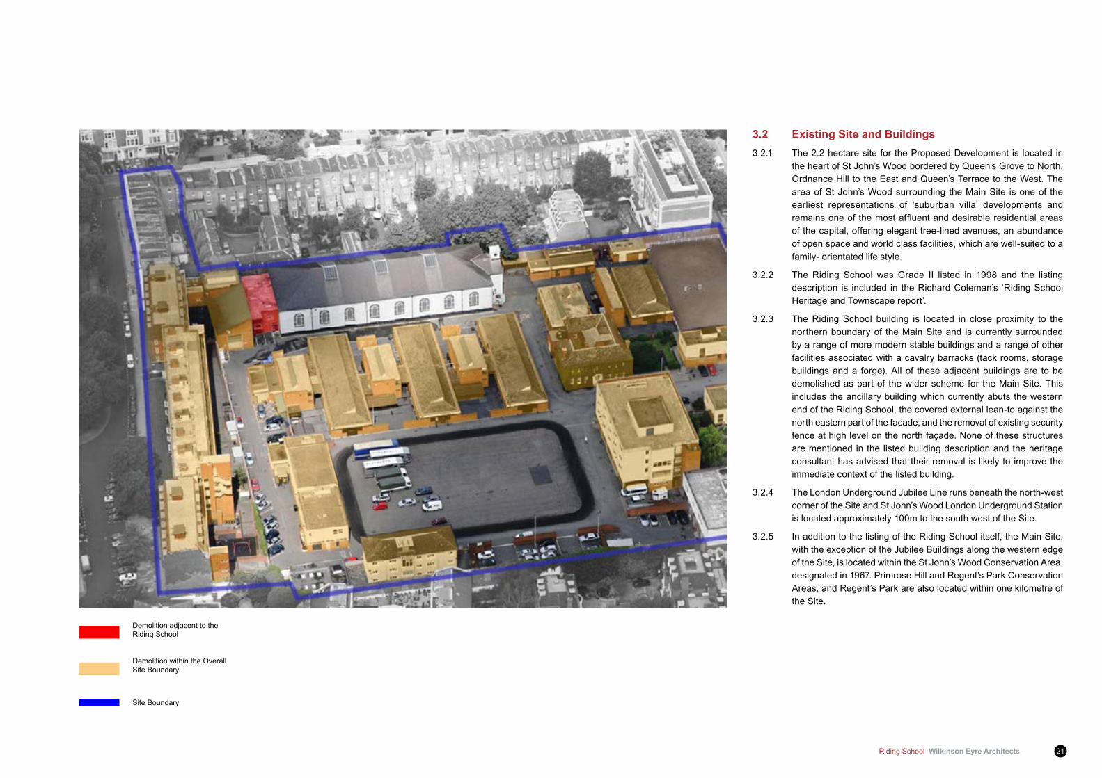
3.2 Existing Site and Buildings3.2.1 The 2.2 hectare site for the Proposed Development is located in
the heart of St John’s Wood bordered by Queen’s Grove to North, Ordnance Hill to the East and Queen’s Terrace to the West. The area of St John’s Wood surrounding the Main Site is one of the earliest representations of ‘suburban villa’ developments and remainsoneof themostaffluentanddesirableresidentialareasof the capital, offering elegant tree-lined avenues, an abundance of open space and world class facilities, which are well-suited to a family- orientated life style.
3.2.2 The Riding School was Grade II listed in 1998 and the listing description is included in the Richard Coleman’s ‘Riding School Heritage and Townscape report’.
3.2.3 The Riding School building is located in close proximity to the northern boundary of the Main Site and is currently surrounded by a range of more modern stable buildings and a range of other facilities associated with a cavalry barracks (tack rooms, storage buildings and a forge). All of these adjacent buildings are to be demolished as part of the wider scheme for the Main Site. This includes the ancillary building which currently abuts the western end of the Riding School, the covered external lean-to against the north eastern part of the facade, and the removal of existing security fence at high level on the north façade. None of these structures are mentioned in the listed building description and the heritage consultant has advised that their removal is likely to improve the immediate context of the listed building.
3.2.4 The London Underground Jubilee Line runs beneath the north-west corner of the Site and St John’s Wood London Underground Station is located approximately 100m to the south west of the Site.
3.2.5 In addition to the listing of the Riding School itself, the Main Site, with the exception of the Jubilee Buildings along the western edge of the Site, is located within the St John’s Wood Conservation Area, designated in 1967. Primrose Hill and Regent’s Park Conservation Areas, and Regent’s Park are also located within one kilometre of the Site.
Demolition adjacent to the Riding School
Demolition within the Overall Site Boundary
Site Boundary
Wilkinson Eyre Architects Riding School22
3 Site Analysis
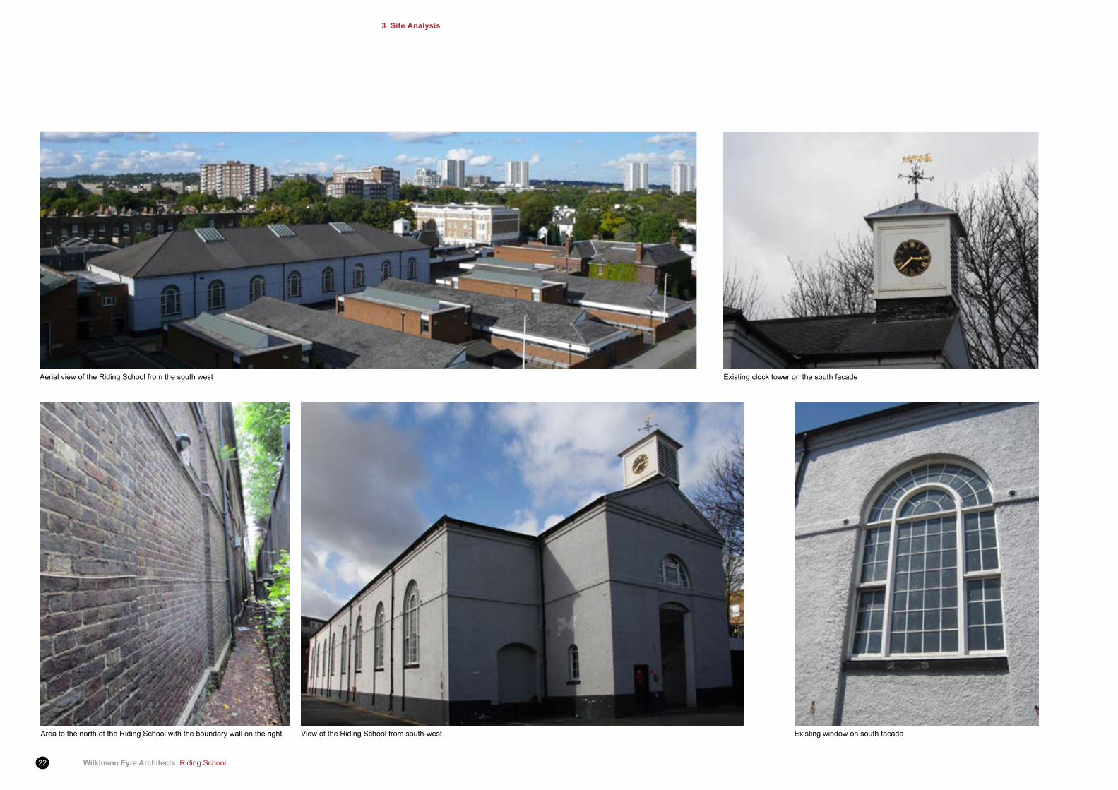
Existing clock tower on the south facade
Area to the north of the Riding School with the boundary wall on the right
Aerial view of the Riding School from the south west
Existing window on south facadeView of the Riding School from south-west

Riding School Wilkinson Eyre Architects 23
Existing internal north elevation view
Existing internal south elevation view Existing Internal timber roof view Existing Internal timber wall paneling view
Existing internal east side view - main entrance and openig at mezzanine level Existing internal timber gate to be retained as historical memory(east facade) but not usable

Wilkinson Eyre Architects Riding School24
3 Site Analysis
Proposed SJWS Masterplan
Service Access
Main Axis - Public pedestrian route
Site Boundary
Existing and Main Entrance to Riding School
New Public Entrance to ‘West Pavilion’Green Areas
Buildings within Overall Site Development

Riding School Wilkinson Eyre Architects 25
Extent of site demolition
3.3 The Riding School and relationship to the proposed main development
3.3.1 The Proposed Development is predominantly residential and consists of a mix of apartments and houses arranged around a new street and Garden Square and is being designed by Squire and Partners. The Development also includes basement accommodation comprising residential floorspace, car parking,plant, storage and service areas, as well as the further areas of residents facilities which are being designed by Wilkinson Eyre. The Riding School is to be connected to the rest of the Development at Lower Ground level so that the different parts of the amenity facilities are linked and so that secure internal access to the Riding School is provided for residents at this level.
3.3.2 The primary entrance to the Proposed Development will be from Ordnance Hill. These blocks frame a view of the east elevation of the Riding School with its distinctive clock tower and this new view into the Site will form the initial impression of the Development for most visitors as well as passersby.
3.3.3 A new Riding School Square will be created immediately to the east of the Riding School. The square will contain a small number of visitor car parking spaces and will allow people arriving at the Development to be greeted by a member of staff. The square will also contain a piece of public art and potentially a water feature.
3.3.4 The Riding School, together with Residential Blocks 2, 3 and 6, will act as a frame for the proposed Garden Square, providing a sense of enclosure and containment to this new green space at the heart of the Development. A key consideration in the development of the design proposals for the Riding School has been establishing how the building could be sensitively connected to the Garden Square in order to promote permeability across the Site and create a direct connection between its refurbished interior spaces and the Garden Square.
Proposed external 3D view from the Riding School Square
Wilkinson Eyre Architects Riding School26
3 Site Analysis
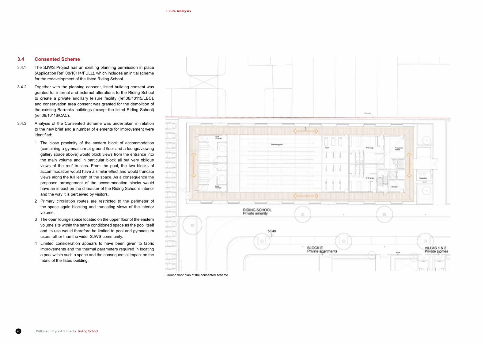
3.4 Consented Scheme3.4.1 The SJWS Project has an existing planning permission in place
(Application Ref. 08/10114/FULL), which includes an initial scheme for the redevelopment of the listed Riding School.
3.4.2 Together with the planning consent, listed building consent was granted for internal and external alterations to the Riding School to create a private ancillary leisure facility (ref.08/10115/LBC), and conservation area consent was granted for the demolition of the existing Barracks buildings (except the listed Riding School) (ref.08/10116/CAC).
3.4.3 Analysis of the Consented Scheme was undertaken in relation to the new brief and a number of elements for improvement were identified:
1 The close proximity of the eastern block of accommodation (containingagymnasiumatgroundfloorandalounge/viewinggallery space above) would block views from the entrance into the main volume and in particular block all but very oblique views of the roof trusses. From the pool, the two blocks of accommodation would have a similar effect and would truncate views along the full length of the space. As a consequence the proposed arrangement of the accommodation blocks would have an impact on the character of the Riding School’s interior and the way it is perceived by visitors.
2 Primary circulation routes are restricted to the perimeter of the space again blocking and truncating views of the interior volume.
3 Theopenloungespacelocatedontheupperflooroftheeasternvolume sits within the same conditioned space as the pool itself and its use would therefore be limited to pool and gymnasium users rather than the wider SJWS community.
4 Limited consideration appears to have been given to fabric improvements and the thermal parameters required in locating a pool within such a space and the consequential impact on the fabric of the listed building.
Groundfloorplanoftheconsentedscheme
Riding School Wilkinson Eyre Architects 27
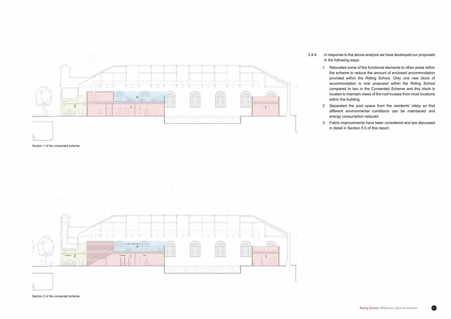
Section 1 of the consented scheme
Section 2 of the consented scheme
3.4.4 In response to the above analysis we have developed our proposals in the following ways:
1 Relocated some of the functional elements to other areas within the scheme to reduce the amount of enclosed accommodation provided within the Riding School. Only one new block of accommodation is now proposed within the Riding School compared to two in the Consented Scheme and this block is located to maintain views of the roof trusses from most locations within the building.
2 Separated the pool space from the residents’ lobby so that different environmental conditions can be maintained and energy consumption reduced.
3 Fabric improvements have been considered and are discussed in detail in Section 5.0 of this report.
Wilkinson Eyre Architects Riding School28
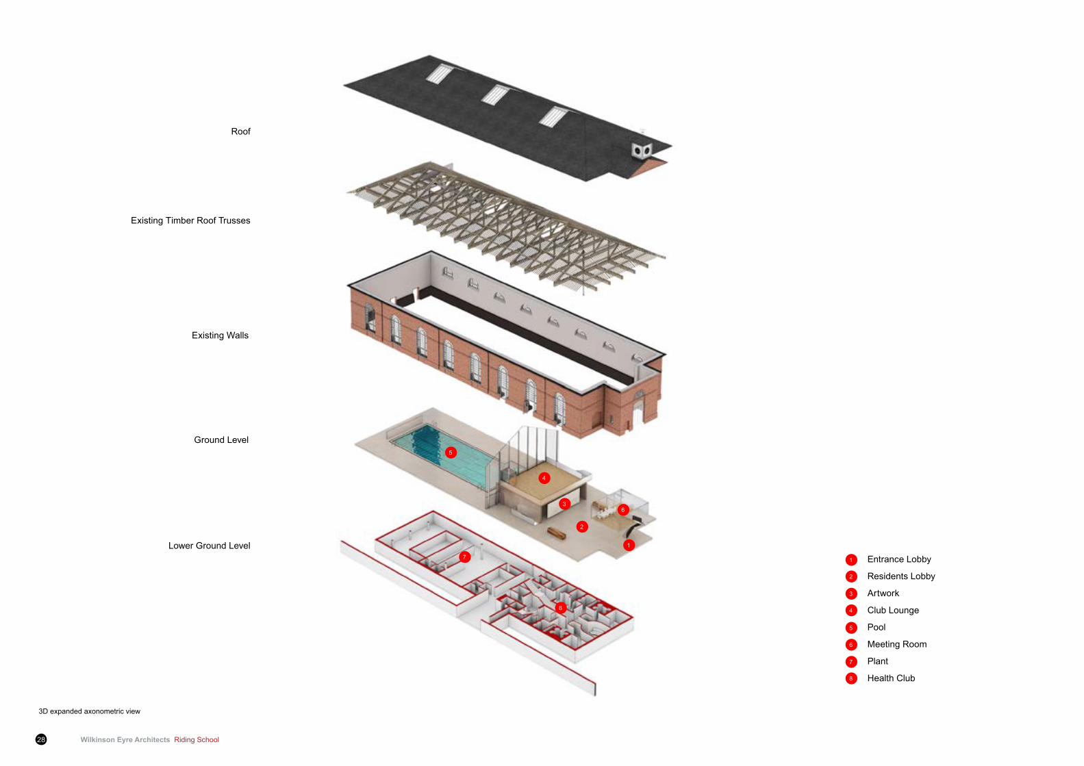
3D expanded axonometric view
Roof
Existing Timber Roof Trusses
Existing Walls
Ground Level
Lower Ground LevelEntrance Lobby
Residents Lobby
Artwork
Club Lounge
Pool
Meeting Room
Plant
Health Club
6
1
2
3
4
5
7
8
2
1
3
8
5
4
6
7
Riding School Wilkinson Eyre Architects 29
4 Architectural design proposal
Functional relationship diagram
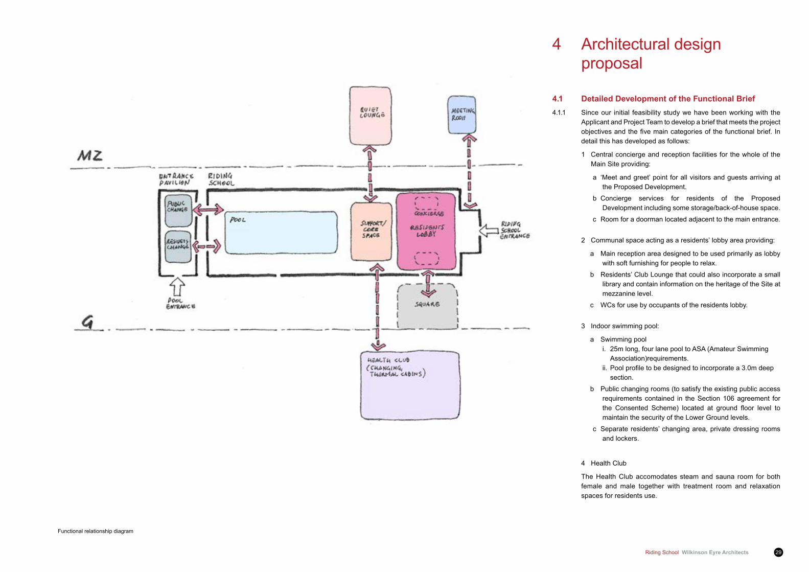
4.1 Detailed Development of the functional Brief4.1.1 Since our initial feasibility study we have been working with the
Applicant and Project Team to develop a brief that meets the project objectivesandthefivemaincategoriesof thefunctionalbrief. Indetail this has developed as follows:
1 Central concierge and reception facilities for the whole of the Main Site providing:
a ‘Meet and greet’ point for all visitors and guests arriving at the Proposed Development.
b Concierge services for residents of the Proposed Development including some storage/back-of-house space.
c Room for a doorman located adjacent to the main entrance.
2 Communal space acting as a residents’ lobby area providing:
a Main reception area designed to be used primarily as lobby with soft furnishing for people to relax.
b Residents’ Club Lounge that could also incorporate a small library and contain information on the heritage of the Site at mezzanine level.
c WCs for use by occupants of the residents lobby.
3 Indoor swimming pool:
a Swimming pool i. 25m long, four lane pool to ASA (Amateur Swimming Association)requirements. ii.Poolprofiletobedesignedtoincorporatea3.0mdeep section.
b Public changing rooms (to satisfy the existing public access requirements contained in the Section 106 agreement for the Consented Scheme) located at ground floor level tomaintain the security of the Lower Ground levels.
c Separate residents’ changing area, private dressing rooms and lockers.
4 Health Club
The Health Club accomodates steam and sauna room for both female and male together with treatment room and relaxation spaces for residents use.
Wilkinson Eyre Architects Riding School30
4 Architectural Design Proposal
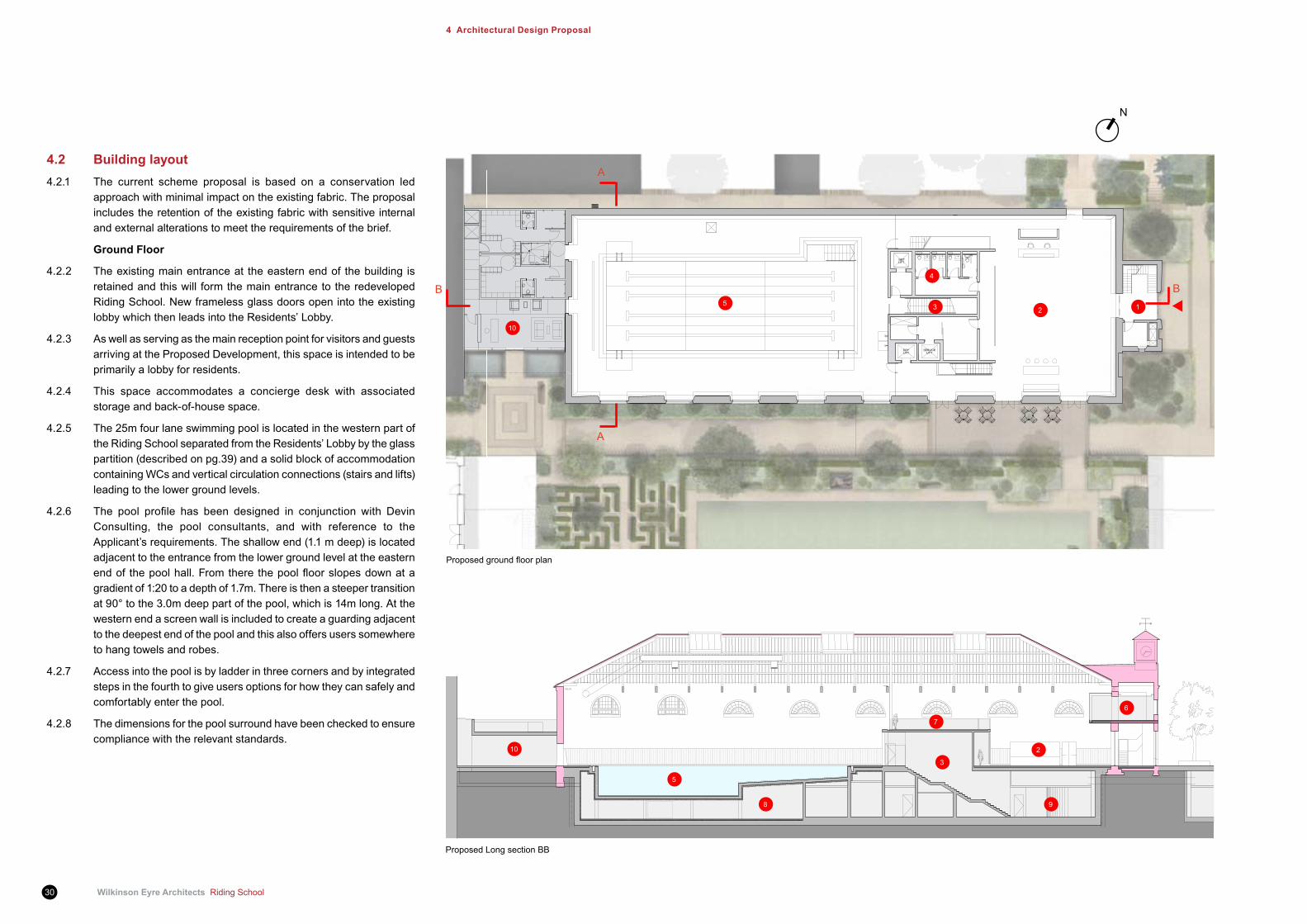
4.2 Building layout4.2.1 The current scheme proposal is based on a conservation led
approach with minimal impact on the existing fabric. The proposal includes the retention of the existing fabric with sensitive internal and external alterations to meet the requirements of the brief.
Ground floor
4.2.2 The existing main entrance at the eastern end of the building is retained and this will form the main entrance to the redeveloped Riding School. New frameless glass doors open into the existing lobby which then leads into the Residents’ Lobby.
4.2.3 As well as serving as the main reception point for visitors and guests arriving at the Proposed Development, this space is intended to be primarily a lobby for residents.
4.2.4 This space accommodates a concierge desk with associated storage and back-of-house space.
4.2.5 The 25m four lane swimming pool is located in the western part of the Riding School separated from the Residents’ Lobby by the glass partition (described on pg.39) and a solid block of accommodation containing WCs and vertical circulation connections (stairs and lifts) leading to the lower ground levels.
4.2.6 The pool profile has been designed in conjunction with DevinConsulting, the pool consultants, and with reference to the Applicant’s requirements. The shallow end (1.1 m deep) is located adjacent to the entrance from the lower ground level at the eastern endof thepoolhall.Fromtherethepoolfloorslopesdownatagradient of 1:20 to a depth of 1.7m. There is then a steeper transition at 90° to the 3.0m deep part of the pool, which is 14m long. At the western end a screen wall is included to create a guarding adjacent to the deepest end of the pool and this also offers users somewhere to hang towels and robes.
4.2.7 Access into the pool is by ladder in three corners and by integrated steps in the fourth to give users options for how they can safely and comfortably enter the pool.
4.2.8 The dimensions for the pool surround have been checked to ensure compliance with the relevant standards.
Proposedgroundfloorplan
Proposed Long section BB
A
A
BB12
4
35
N
2
3
5
9
6
7
8
10
10
Riding School Wilkinson Eyre Architects 31
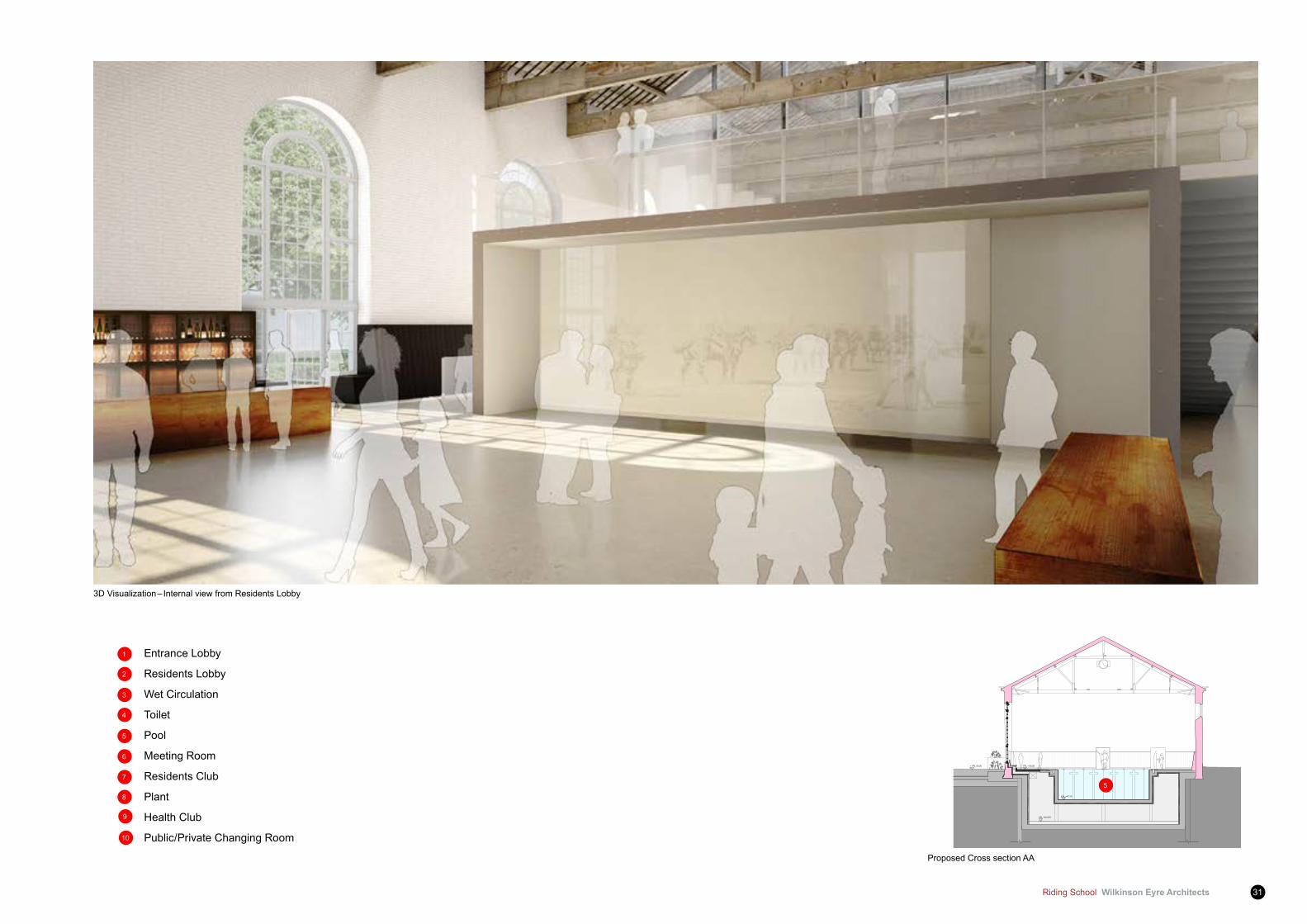
Proposed Cross section AA
3D Visualization – Internal view from Residents Lobby
Entrance Lobby
Residents Lobby
Wet Circulation
Toilet
Pool
Meeting Room
Residents Club
Plant
Health Club
Public/Private Changing Room
6
1
2
3
4
5
7
8
9
10
5

Wilkinson Eyre Architects Riding School32
4 Architectural Design Proposal
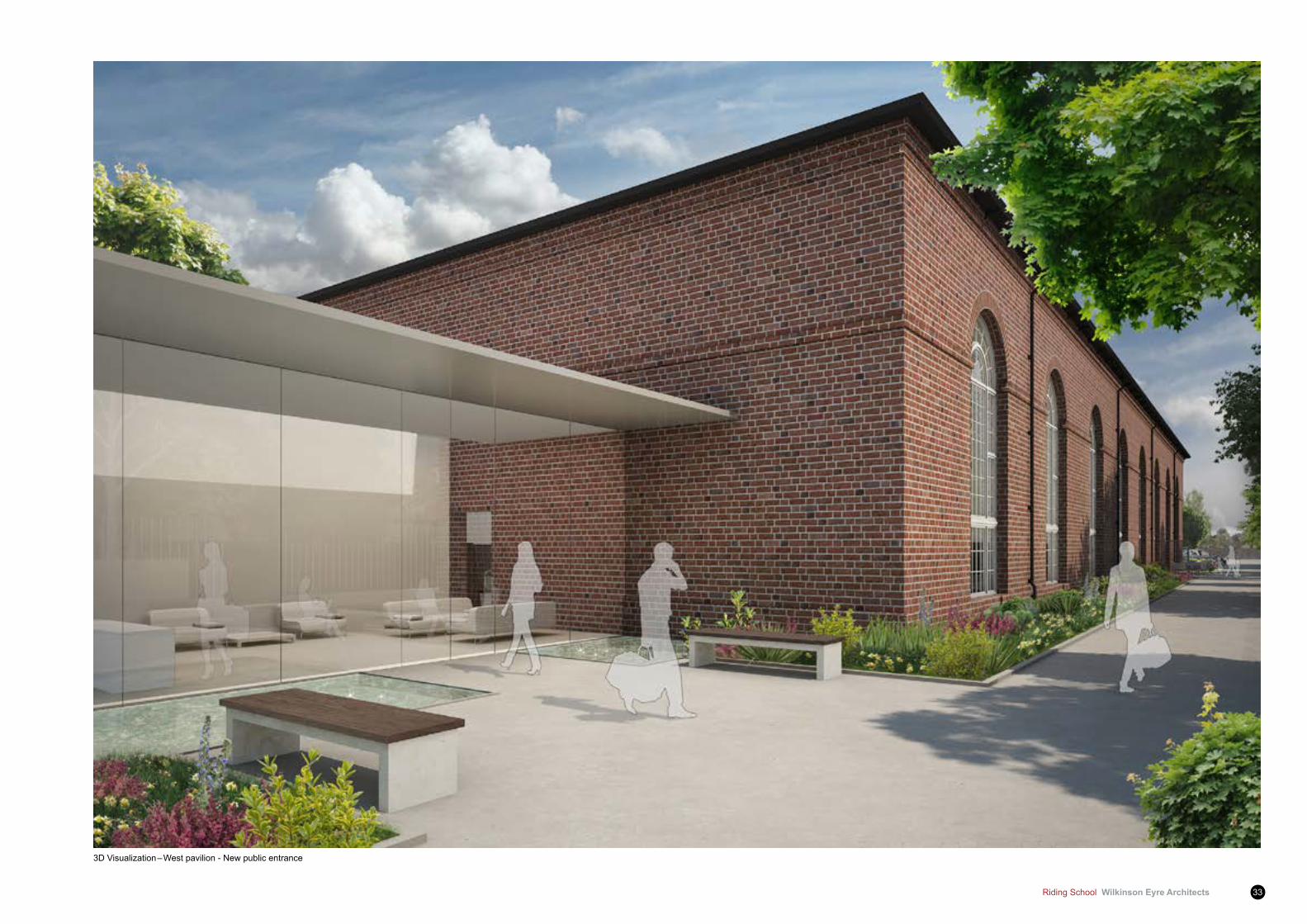
West pavilion
4.2.9 To the west of the Riding School a new pavilion is created to accommodate a separate entrance to the pool and changing rooms for use by the public in order to honour the existing public access requirements contained in the Section 106 agreement for the consented scheme.
4.2.10 This new entrance provides both public access and an access for residents should they prefer to enter the pool at Ground level.
4.2.11 The new western pavilion is set well back from the Riding School facade in order to provide a sensitive and discreet entrance to the public:
4.2.12 It is conceived as an elegant lightweight and minimalist design intervention and is of less volume than the existing which it replaces, enhancing the architectural presence and heritage value of the Grade II listed Riding School building.
Metal canopy precedent
West pavilion part plan
Riding School Wilkinson Eyre Architects 33
3D Visualization – West pavilion - New public entrance
Wilkinson Eyre Architects Riding School34
4 Architectural Design Proposal
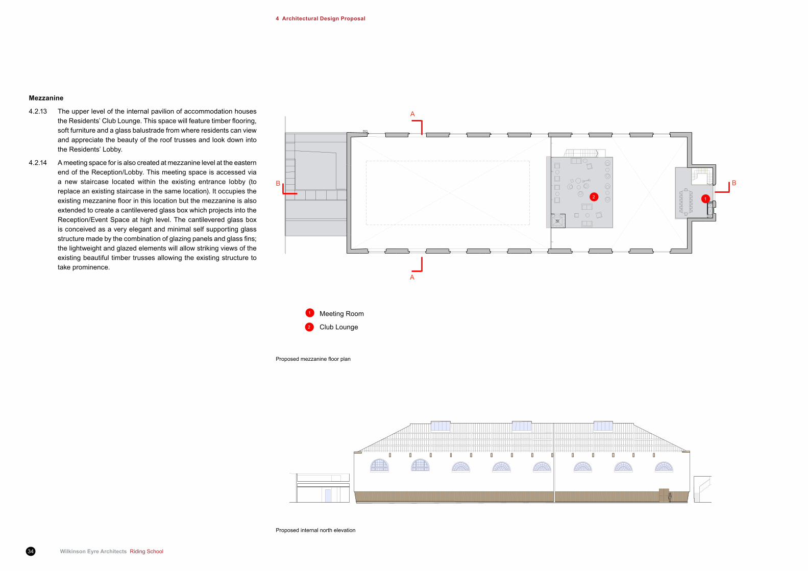
Mezzanine
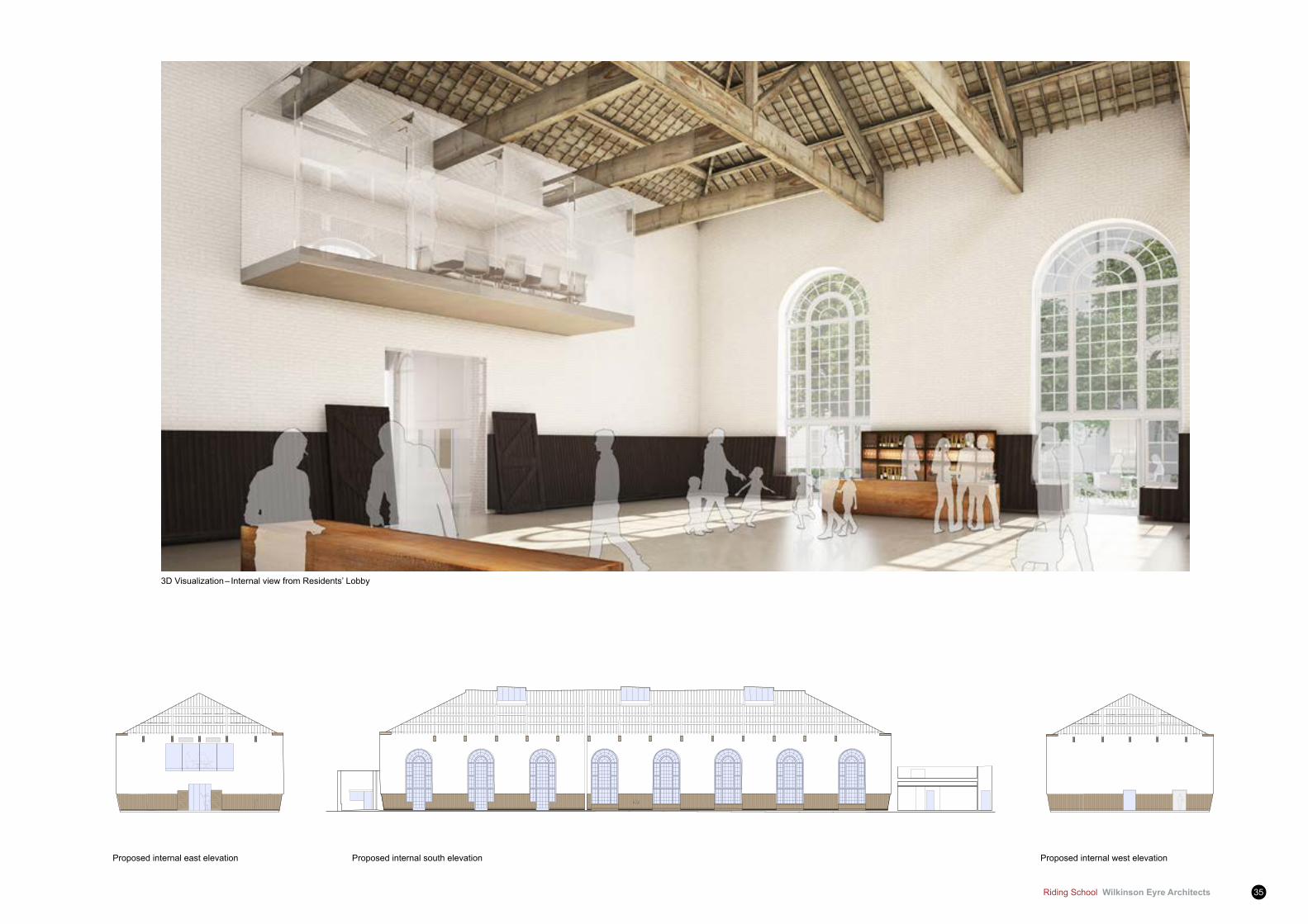
4.2.13 The upper level of the internal pavilion of accommodation houses theResidents’ClubLounge.Thisspacewillfeaturetimberflooring,soft furniture and a glass balustrade from where residents can view and appreciate the beauty of the roof trusses and look down into the Residents’ Lobby.
4.2.14 A meeting space for is also created at mezzanine level at the eastern end of the Reception/Lobby. This meeting space is accessed via a new staircase located within the existing entrance lobby (to replace an existing staircase in the same location). It occupies the existingmezzaninefloorinthislocationbutthemezzanineisalsoextended to create a cantilevered glass box which projects into the Reception/Event Space at high level. The cantilevered glass box is conceived as a very elegant and minimal self supporting glass structuremadebythecombinationofglazingpanelsandglassfins;the lightweight and glazed elements will allow striking views of the existing beautiful timber trusses allowing the existing structure to take prominence.
Proposedmezzaninefloorplan
Meeting Room
Club Lounge
Proposed internal north elevation
12
1
2
BB
A
A
Riding School Wilkinson Eyre Architects 35
3D Visualization – Internal view from Residents’ Lobby
Proposed internal south elevation Proposed internal west elevationProposed internal east elevation
Wilkinson Eyre Architects Riding School36
4 Architectural Design Proposal
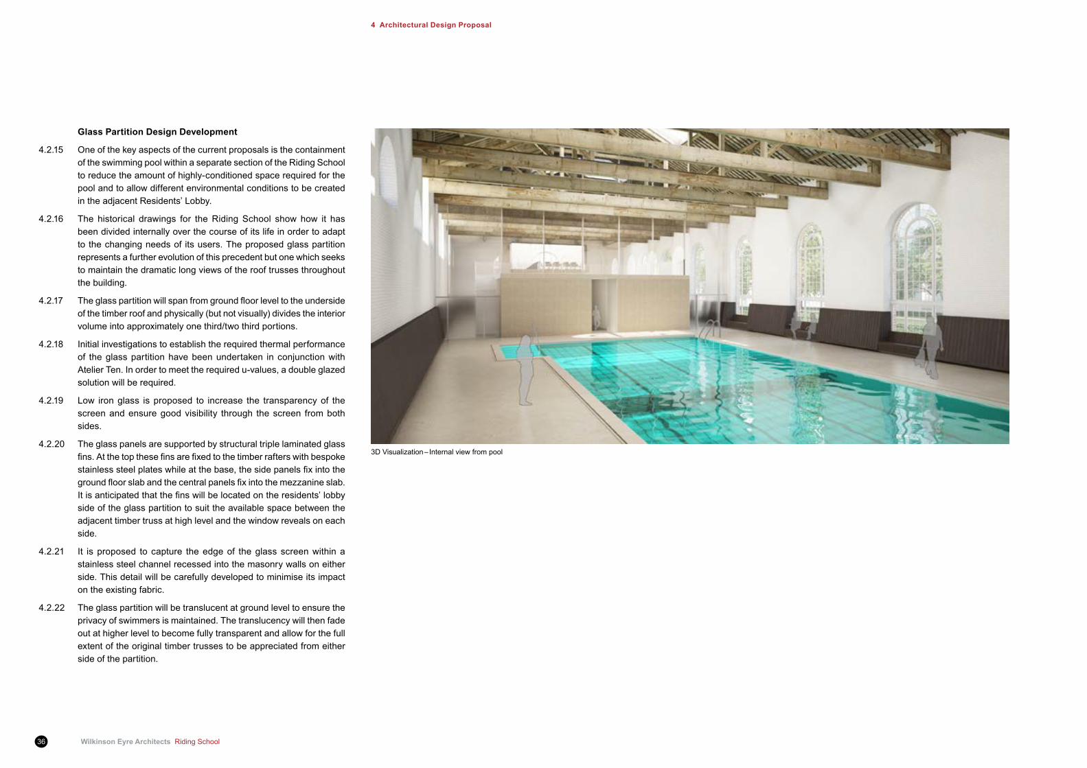
Glass Partition Design Development
4.2.15 One of the key aspects of the current proposals is the containment of the swimming pool within a separate section of the Riding School to reduce the amount of highly-conditioned space required for the pool and to allow different environmental conditions to be created in the adjacent Residents’ Lobby.
4.2.16 The historical drawings for the Riding School show how it has been divided internally over the course of its life in order to adapt to the changing needs of its users. The proposed glass partition represents a further evolution of this precedent but one which seeks to maintain the dramatic long views of the roof trusses throughout the building.
4.2.17 Theglasspartitionwillspanfromgroundfloorleveltotheundersideof the timber roof and physically (but not visually) divides the interior volume into approximately one third/two third portions.
4.2.18 Initial investigations to establish the required thermal performance of the glass partition have been undertaken in conjunction with Atelier Ten. In order to meet the required u-values, a double glazed solution will be required.
4.2.19 Low iron glass is proposed to increase the transparency of the screen and ensure good visibility through the screen from both sides.
4.2.20 The glass panels are supported by structural triple laminated glass fins.Atthetopthesefinsarefixedtothetimberrafterswithbespokestainlesssteelplateswhileatthebase,thesidepanelsfixintothegroundfloorslabandthecentralpanelsfixintothemezzanineslab.Itisanticipatedthatthefinswillbelocatedontheresidents’lobbyside of the glass partition to suit the available space between the adjacent timber truss at high level and the window reveals on each side.
4.2.21 It is proposed to capture the edge of the glass screen within a stainless steel channel recessed into the masonry walls on either side. This detail will be carefully developed to minimise its impact on the existing fabric.
4.2.22 The glass partition will be translucent at ground level to ensure the privacy of swimmers is maintained. The translucency will then fade out at higher level to become fully transparent and allow for the full extent of the original timber trusses to be appreciated from either side of the partition.
3D Visualization – Internal view from pool

Riding School Wilkinson Eyre Architects 37
Proposed internal glass wall elevation
Wilkinson Eyre Architects Riding School38
4 Architectural Design Proposal
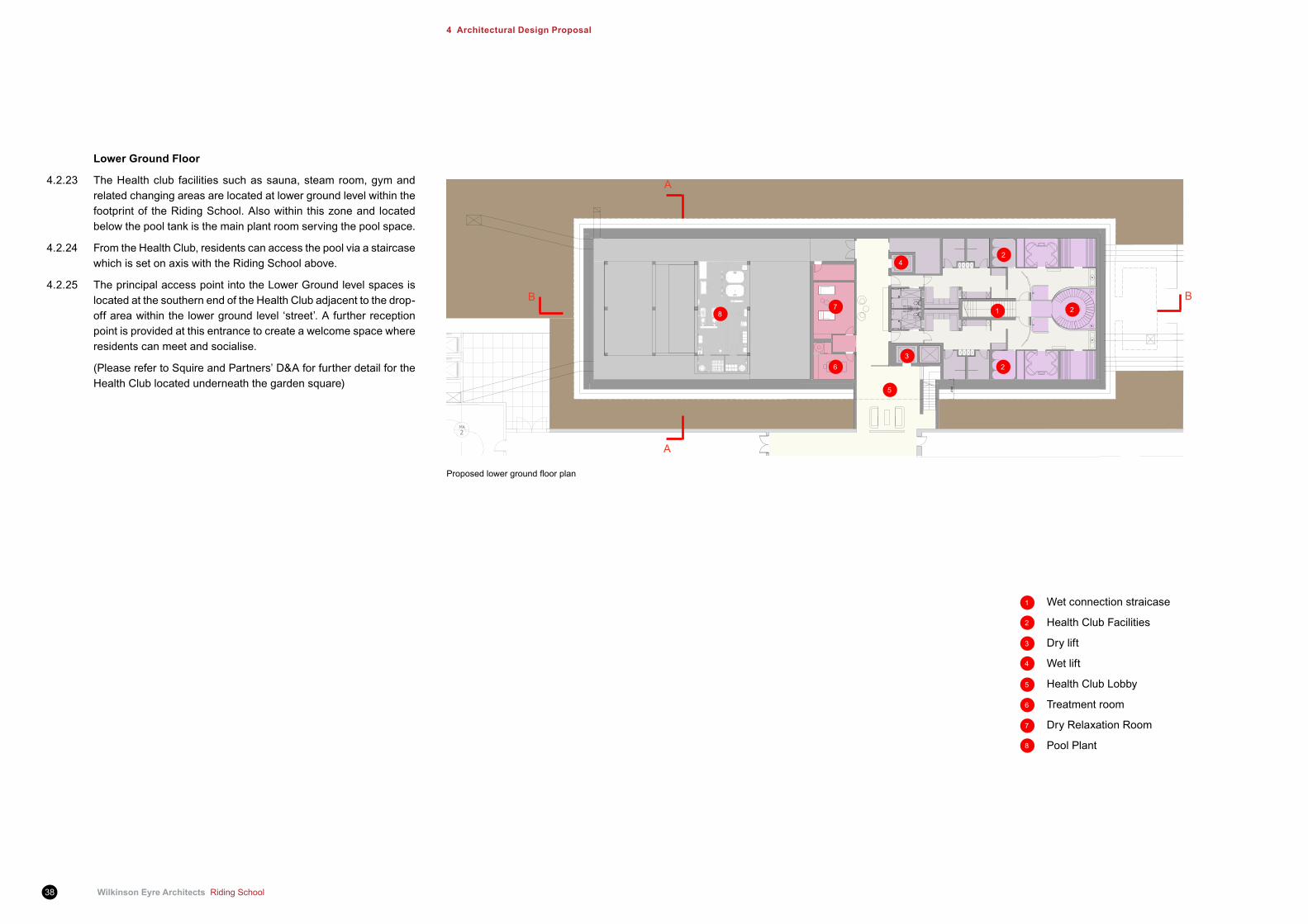
Proposedlowergroundfloorplan
Lower Ground floor
4.2.23 The Health club facilities such as sauna, steam room, gym and related changing areas are located at lower ground level within the footprint of the Riding School. Also within this zone and located below the pool tank is the main plant room serving the pool space.
4.2.24 From the Health Club, residents can access the pool via a staircase which is set on axis with the Riding School above.
4.2.25 The principal access point into the Lower Ground level spaces is located at the southern end of the Health Club adjacent to the drop-off area within the lower ground level ‘street’. A further reception point is provided at this entrance to create a welcome space where residents can meet and socialise.
(Please refer to Squire and Partners’ D&A for further detail for the Health Club located underneath the garden square)
B
A
A
B
Wet connection straicase
Health Club Facilities
Dry lift
Wet lift
Health Club Lobby
Treatment room
Dry Relaxation Room
Pool Plant
6
1
2
3
4
5
7
8
1 2
3
4
5
6
78
2
2
Riding School Wilkinson Eyre Architects 39
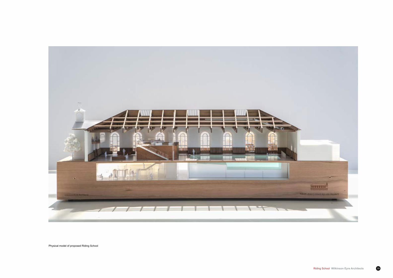
Physical model of proposed Riding School
Wilkinson Eyre Architects Riding School40
4 Architectural Design Proposal
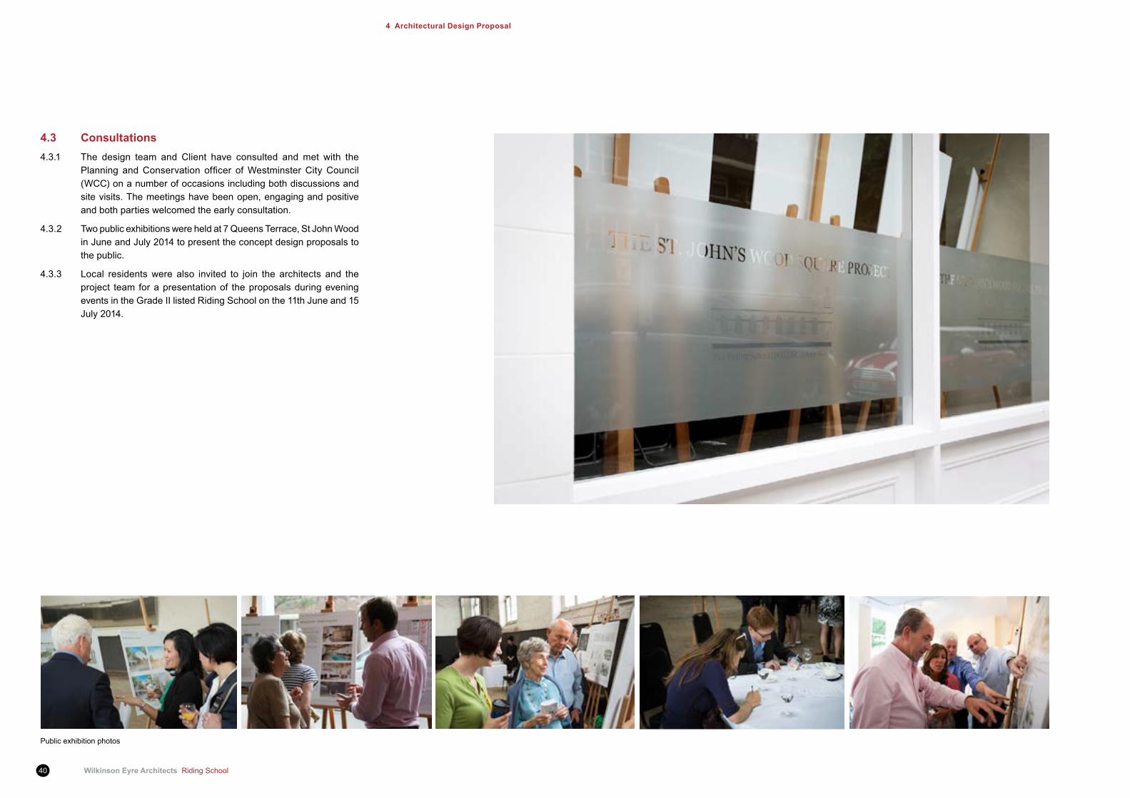
4.3 Consultations4.3.1 The design team and Client have consulted and met with the
Planning andConservation officer ofWestminsterCityCouncil(WCC) on a number of occasions including both discussions and site visits. The meetings have been open, engaging and positive and both parties welcomed the early consultation.
4.3.2 Two public exhibitions were held at 7 Queens Terrace, St John Wood in June and July 2014 to present the concept design proposals to the public.
4.3.3 Local residents were also invited to join the architects and the project team for a presentation of the proposals during evening events in the Grade II listed Riding School on the 11th June and 15 July 2014.
Public exhibition photos
Riding School Wilkinson Eyre Architects 41
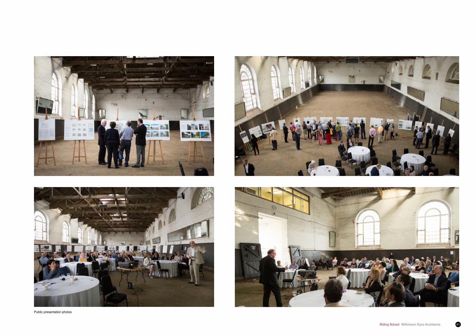
Public presentation photos

Wilkinson Eyre Architects Riding School42
South facade render option
South facade brickwork option
Riding School Wilkinson Eyre Architects 43
5.2 External fabric Proposal External walls
5.2.1 The existing external walls of the Riding School are to be retained. Historical sketches and some photographs show the external facades to have been brickwork similar to that still present on the north elevation. The current coating of rough render (which has been applied with a cementitious mix) is thought therefore not to be original to the building and is at present in a poor condition putting the fabric at risk of long term deterioration.
5.2.2 Extensive in-depth research including condensation analysis and test sampling have been undertaken to investigate whether retaining and refurbishing the existing render, remove existing render and apply new lime render, or revealing the original brickwork was the most appropriate option in terms of heritage, architectural and technical/environmental feasibility.
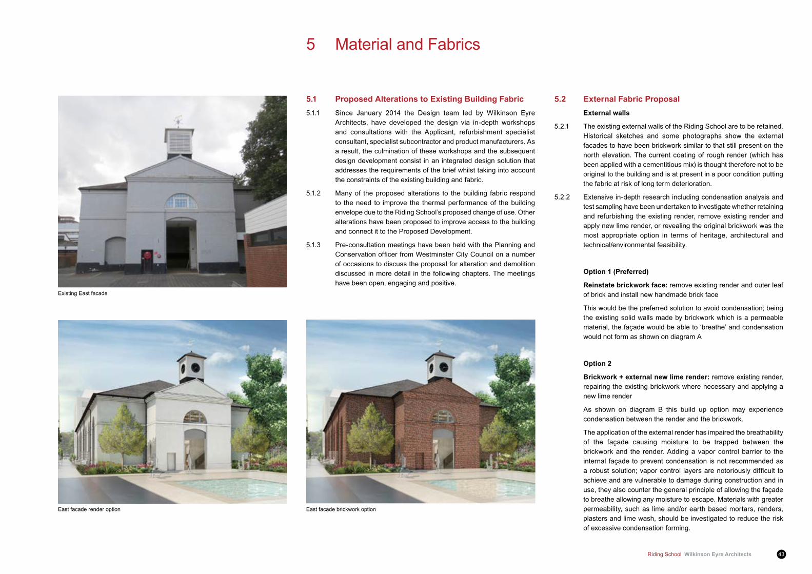
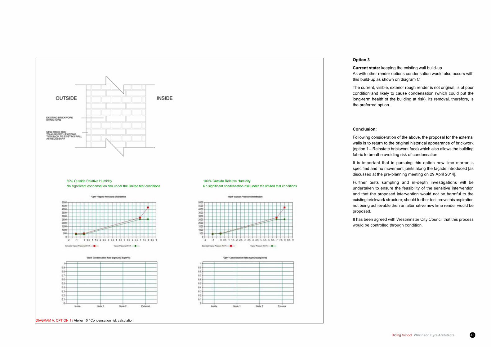
Option 1 (Preferred)
Reinstate brickwork face: remove existing render and outer leaf of brick and install new handmade brick face
This would be the preferred solution to avoid condensation; being the existing solid walls made by brickwork which is a permeable material, the façade would be able to ‘breathe’ and condensation would not form as shown on diagram A
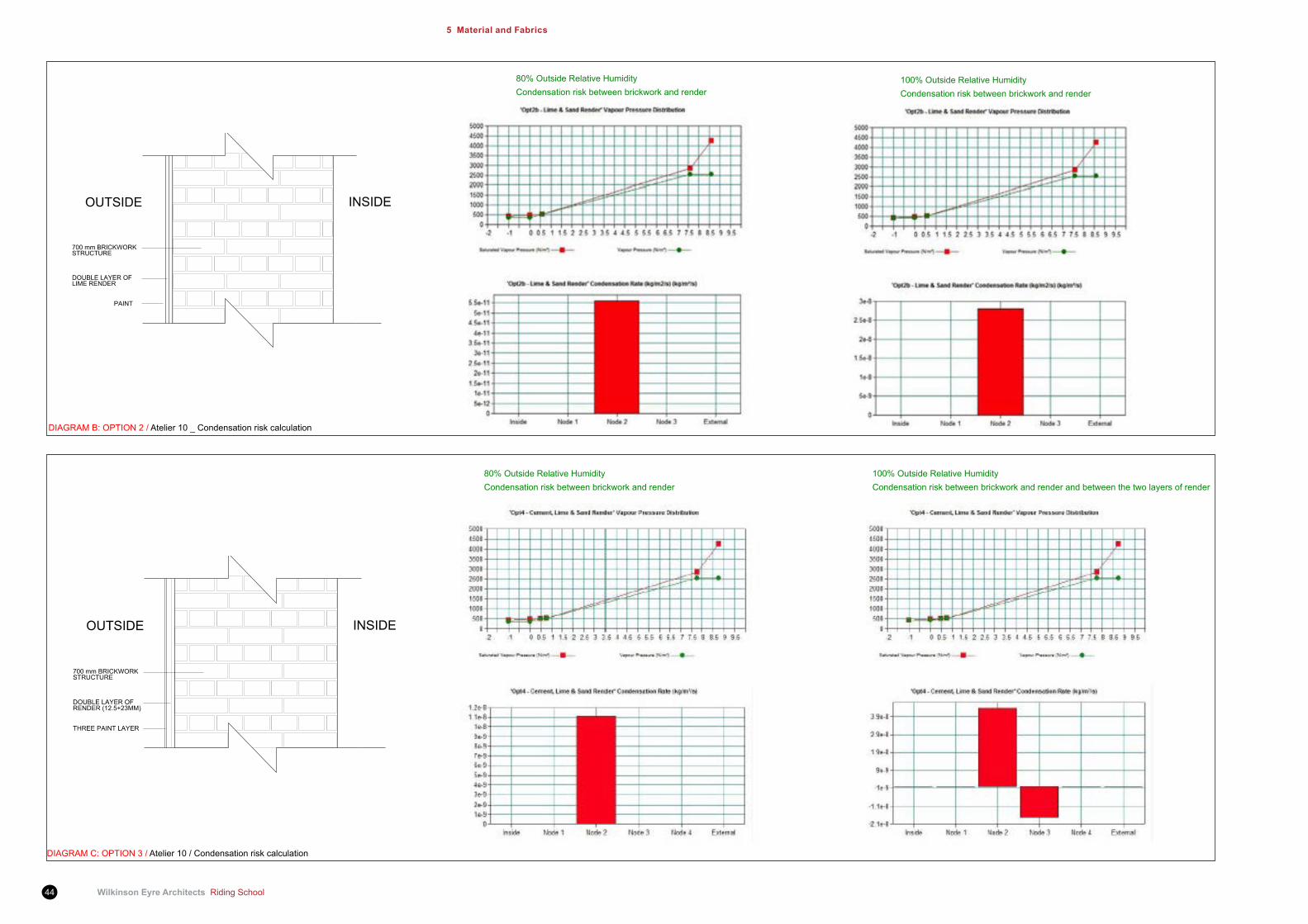
Option 2
Brickwork + external new lime render: remove existing render, repairing the existing brickwork where necessary and applying a new lime render
As shown on diagram B this build up option may experience condensation between the render and the brickwork.
The application of the external render has impaired the breathability of the façade causing moisture to be trapped between the brickwork and the render. Adding a vapor control barrier to the internal façade to prevent condensation is not recommended as arobustsolution;vaporcontrol layersarenotoriouslydifficult toachieve and are vulnerable to damage during construction and in use, they also counter the general principle of allowing the façade to breathe allowing any moisture to escape. Materials with greater permeability, such as lime and/or earth based mortars, renders, plasters and lime wash, should be investigated to reduce the risk of excessive condensation forming.
East facade render option
5 Material and Fabrics
5.1 Proposed Alterations to Existing Building fabric5.1.1 Since January 2014 the Design team led by Wilkinson Eyre
Architects, have developed the design via in-depth workshops and consultations with the Applicant, refurbishment specialist consultant, specialist subcontractor and product manufacturers. As a result, the culmination of these workshops and the subsequent design development consist in an integrated design solution that addresses the requirements of the brief whilst taking into account the constraints of the existing building and fabric.
5.1.2 Many of the proposed alterations to the building fabric respond to the need to improve the thermal performance of the building envelope due to the Riding School’s proposed change of use. Other alterations have been proposed to improve access to the building and connect it to the Proposed Development.
5.1.3 Pre-consultation meetings have been held with the Planning and ConservationofficerfromWestminsterCityCouncilonanumberof occasions to discuss the proposal for alteration and demolition discussed in more detail in the following chapters. The meetings have been open, engaging and positive.
Existing East facade
East facade brickwork option
Wilkinson Eyre Architects Riding School44
5 Material and fabrics
100% Outside Relative HumidityCondensation risk between brickwork and render
80% Outside Relative HumidityCondensation risk between brickwork and render
DIAGRAM B: OPTION 2 / Atelier 10 _ Condensation risk calculation
80% Outside Relative HumidityCondensation risk between brickwork and render
100% Outside Relative HumidityCondensation risk between brickwork and render and between the two layers of render
DIAGRAM C: OPTION 3 / Atelier 10 / Condensation risk calculation
Riding School Wilkinson Eyre Architects 45
80% Outside Relative HumidityNosignificantcondensationriskunderthelimitedtestconditions
100% Outside Relative HumidityNosignificantcondensationriskunderthelimitedtestconditions
DIAGRAM A: OPTION 1 / Atelier 10 / Condensation risk calculation
Option 3
Current state: keeping the existing wall build-up As with other render options condensation would also occurs with
this build-up as shown on diagram C
The current, visible, exterior rough render is not original, is of poor condition and likely to cause condensation (which could put the long-term health of the building at risk). Its removal, therefore, is the preferred option.
Conclusion:
Following consideration of the above, the proposal for the external walls is to return to the original historical appearance of brickwork (option 1 – Reinstate brickwork face) which also allows the building fabric to breathe avoiding risk of condensation.
It is important that in pursuing this option new lime mortar is specifiedandnomovementjointsalongthefaçadeintroduced[asdiscussed at the pre-planning meeting on 29 April 2014].
Further tests sampling and in-depth investigations will be undertaken to ensure the feasibility of the sensitive intervention and that the proposed intervention would not be harmful to the existing brickwork structure; should further test prove this aspiration not being achievable then an alternative new lime render would be proposed.
It has been agreed with Westminster City Council that this process would be controlled through condition.
Wilkinson Eyre Architects Riding School46
5 Material and fabrics
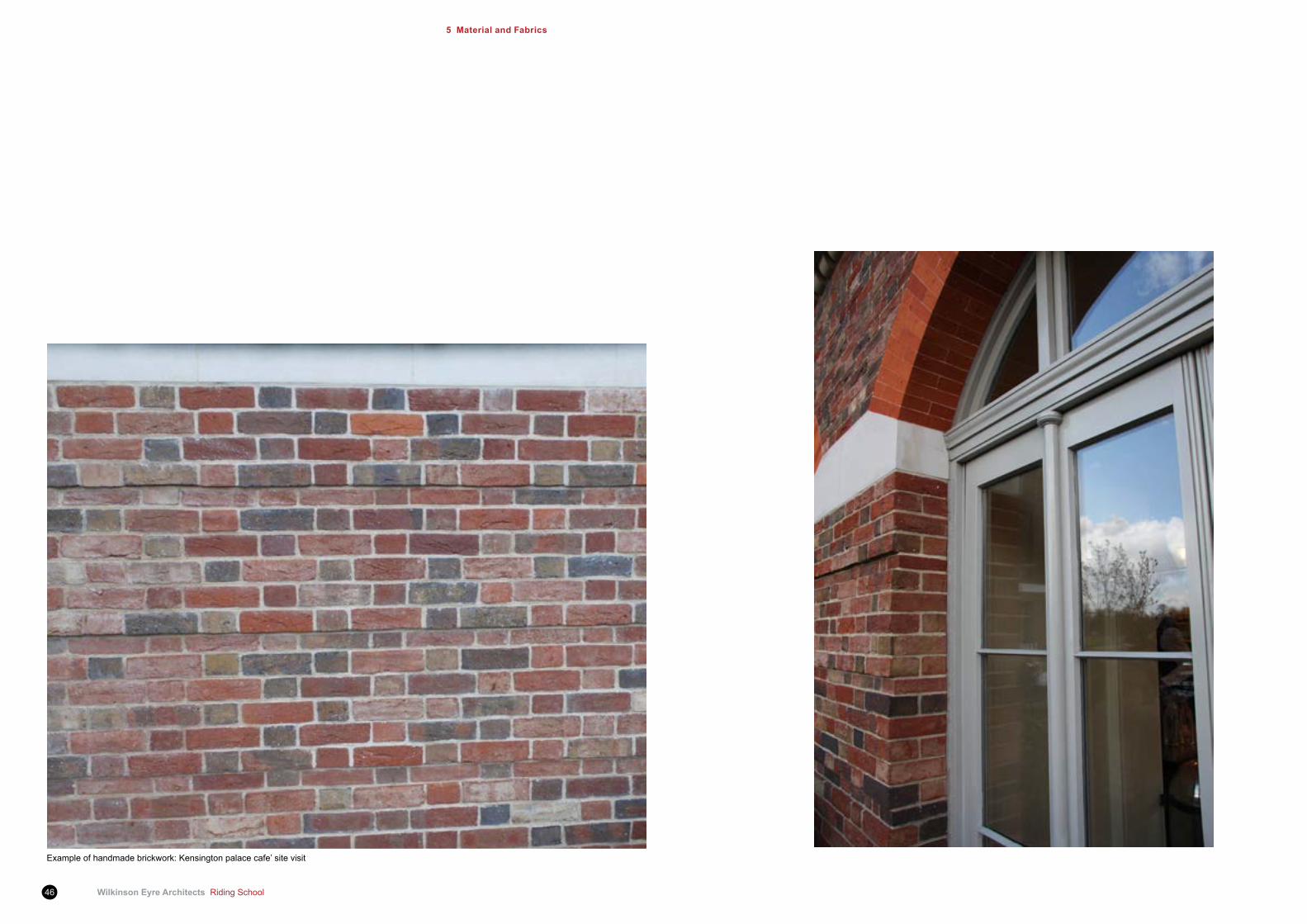
Example of handmade brickwork: Kensington palace cafe’ site visit
Riding School Wilkinson Eyre Architects 47
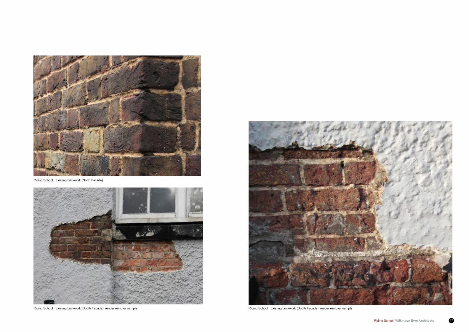
Riding School_ Existing brickwork (North Facade)
Riding School_ Existing brickwork (South Facade)_render removal sampleRiding School_ Existing brickwork (South Facade)_render removal sample

Wilkinson Eyre Architects Riding School48
5 Material and fabrics
Existing south elevation
Proposed south elevation
Windows
5.2.5 All the existing windows in the Riding School are single glazed and although their design matches the original windows, these versions were installed during the refurbishment of the building undertaken by Mayorcas and Guest in 1971.
5.2.6 During a site visit with the refurbishment specialist contractor, the existing windows frame were generally found in a poor but still potentially reusable condition; it is therefore proposed to keep and refurbish the existing main timber frames.
5.2.7 In a similar way to the proposed thermal upgrading of the roof (described later in this document), the upgrading of the windows is very important to ensure that the environmental strategy required to support the operation of the building operates effectively.
5.2.8 In order to improve the thermal performance of the building, it is proposed to re-glaze the existing windows’ sash panels with a new slim double glazing (14mm Slimlite type) to achieve the required U-value of 1.4 W/m²K.
5.2.9 We are also proposing to extend down the windows on the south elevation to improve the connection of the interior spaces to the adjacent Garden Square. Historically, a number of additional openings have been made in this façade to respond to the different uses of the building over its life (refer in particular to Fig.3.13 at page 7 of the ‘Heritage and Alteration Assessment’ report).
5.2.10 A number of options for this proposal have been developed together with the Applicant, heritage consultant and design team and discussed during the pre-planning meetings with the Westminster Planning and Conservation officer. Following consultation withall parties including the public, the design team has given further consideration to the lowering of the windows and the comments received during this consultation process.
5.2.11 In the pool space, it is now proposed to lower the windows down toapproximately700mmoffthefinishedfloorleveltoalignwiththeexisting external plinth detail and to create internal recessed timber bench seats integrated into the window reveals.
5.2.12 IntheResidents’Lobby,thewindowswouldextenddowntofinishedfloorlevelandincludenewdoorsthatopenouttowardstheGardenSquare to allow for a stronger connection between the interior spaces of the building with the new outside space amenities. Careful resolution of the relationship between the existing battered timber lining and the extended window reveals will be developed.

Riding School Wilkinson Eyre Architects 49
5.2.13 This proposal would have the advantages of:
1 Keeping a good harmony/balance to the rhythm of the openings along the façade. It would also retain the historical architectural element of the plinth which is continuous along the perimeter of the historical fabric.
2 Creating new timber bench seats integrated into the window reveals. The proposed timber bench has a dual purpose:
• Enhancing the enjoyment of the space by promoting social interaction and relaxation areas
• It performs as a key detail in supporting the ventilation strategy of the pool hall: it allows concealing the duct for servicing the additional air supply required forming an elegant and sensitive solution in respect to the historical character of the interior of the building
5.2.14 An additional proposal is the reinstatement of one arched opening in the west façade. This is currently bricked up but its reinstatement would provide the access point into the public/private changing room of the new western pavilion.
5.2.15 We also proposed the creation of a new window which will allow view from the reception of the pavilion towards the pool hall and roof’s timber trusses.
5.2.16 Finally, a new glass screen with frameless sliding double doors will be added at the main entrance opening off the Riding School Square and the upper lunette window at mezzanine level (currently in plastic) will be replaced with a new timber frame version.
(See detail drawing 987 – 4100/ 987-4102/ 987- 4101)Bench section detail proposed
Wilkinson Eyre Architects Riding School50
5 Material and fabrics
Windows: Heritage Consultant’s Assessment
5.2.17 Oneofthesignificantfeaturesofthebuildingisitsregularrepetitivefenestration in the south elevation. It is important that this regularity should be rigorously maintained. The building was designed for horses rather than people. The windows were built set high so that horses are not distracted by activity outside. The original designer’s drawings indicate, however, a full height element from ground level at the window position. Without some change to the windows the building will fail to realise its full potential as a place of enjoyment for people, now that horses will not return to the building. Physical connectivity between the inside and the outside landscaped space is desirable and is achieved by lowering the three most eastern window bays. From outside the building there is currently an austere character which presents a mystery as to what activity is going on there. The lowering of all the windows, while instigating the loss of some fabric of the listed building, both sustains its use as a pleasurable leisure activity and as a townscape feature, enjoyed, rather than closed off from the public. The retention of the cill as a strong transom feature, retains a clear representation of the past. Fromaheritagestandpoint,regularityisofgreatersignificancethanregistering the original height.
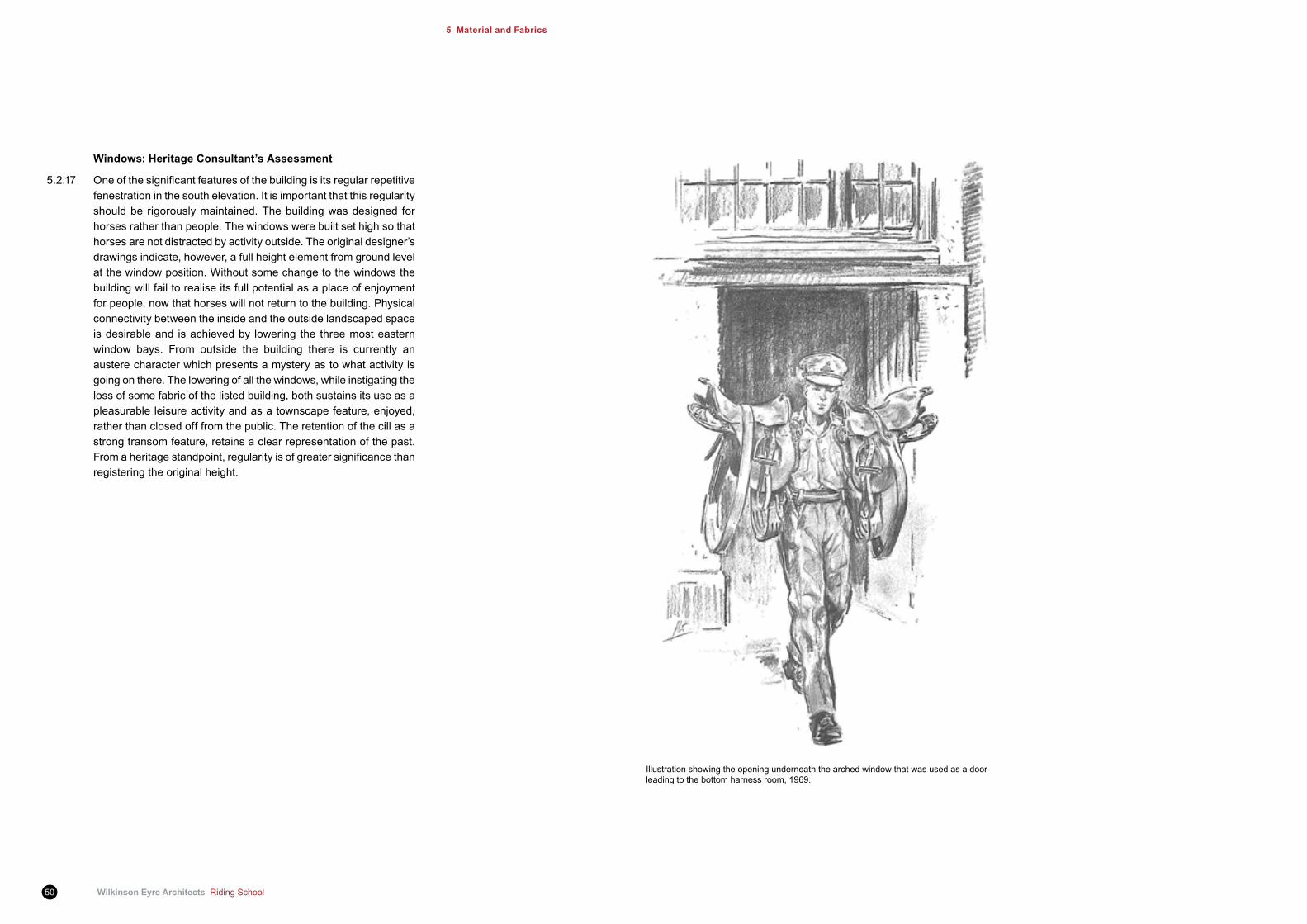
Illustration showing the opening underneath the arched window that was used as a door leading to the bottom harness room, 1969.

Riding School Wilkinson Eyre Architects 51
Diagrams:
5.2.18 The attached diagrams are generally set out in order of success from thetoptothebottom.Theexerciseconfirmstheview,corporatelyheld by the project team, that to drop all windows either to ground levelormosttothebasecourse, istheoptionmostbeneficialtothis heritage asset and to the sustained use and enjoyment of the building into the future.
Wilkinson Eyre Architects Riding School52
5 Material and fabrics
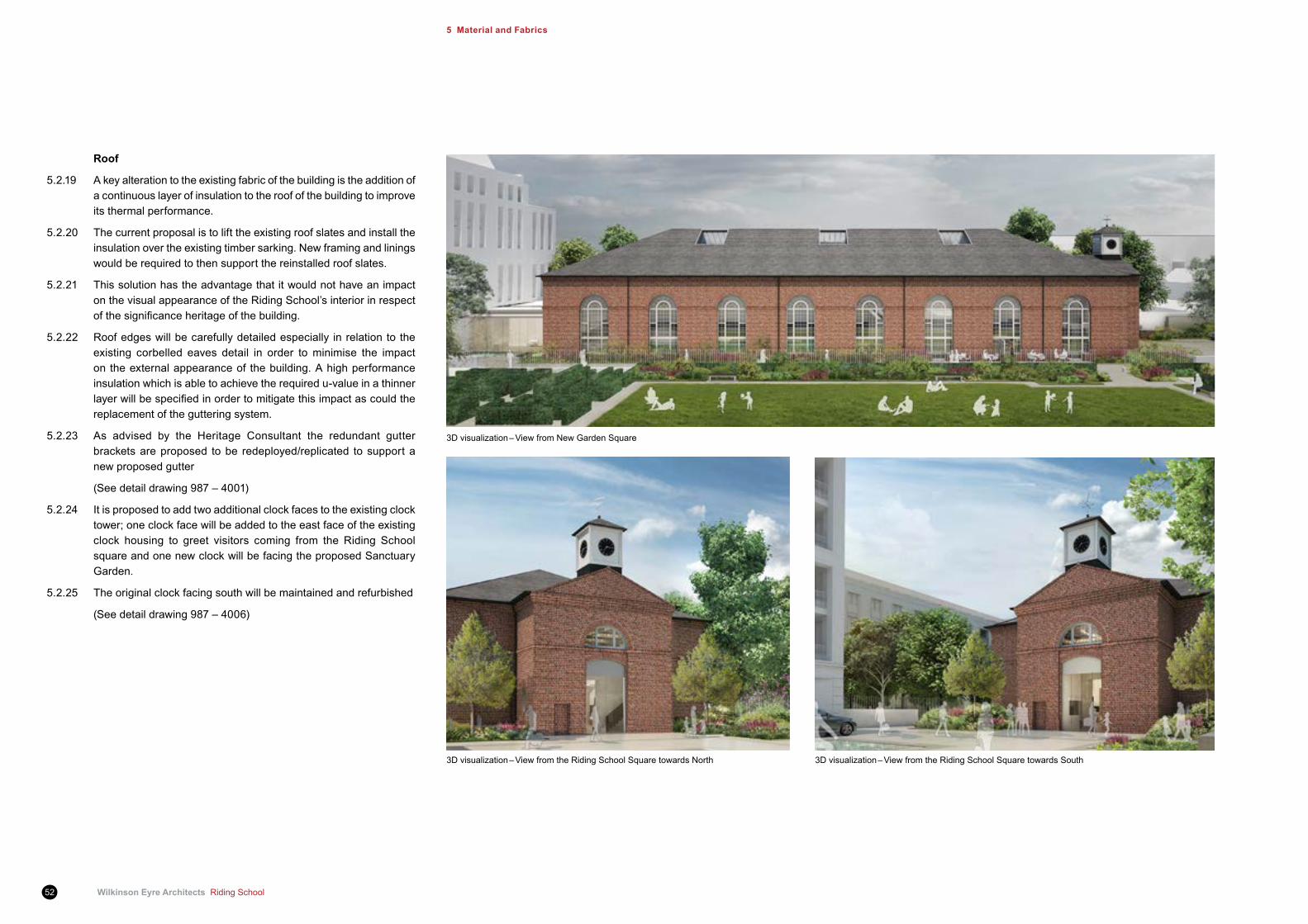
3D visualization – View from New Garden Square
Roof
5.2.19 A key alteration to the existing fabric of the building is the addition of a continuous layer of insulation to the roof of the building to improve its thermal performance.
5.2.20 The current proposal is to lift the existing roof slates and install the insulation over the existing timber sarking. New framing and linings would be required to then support the reinstalled roof slates.
5.2.21 This solution has the advantage that it would not have an impact on the visual appearance of the Riding School’s interior in respect ofthesignificanceheritageofthebuilding.
5.2.22 Roof edges will be carefully detailed especially in relation to the existing corbelled eaves detail in order to minimise the impact on the external appearance of the building. A high performance insulation which is able to achieve the required u-value in a thinner layerwillbespecifiedinordertomitigatethisimpactascouldthereplacement of the guttering system.
5.2.23 As advised by the Heritage Consultant the redundant gutter brackets are proposed to be redeployed/replicated to support a new proposed gutter
(See detail drawing 987 – 4001)
5.2.24 It is proposed to add two additional clock faces to the existing clock tower; one clock face will be added to the east face of the existing clock housing to greet visitors coming from the Riding School square and one new clock will be facing the proposed Sanctuary Garden.
5.2.25 The original clock facing south will be maintained and refurbished
(See detail drawing 987 – 4006)
3D visualization – View from the Riding School Square towards North 3D visualization – View from the Riding School Square towards South
Riding School Wilkinson Eyre Architects 53
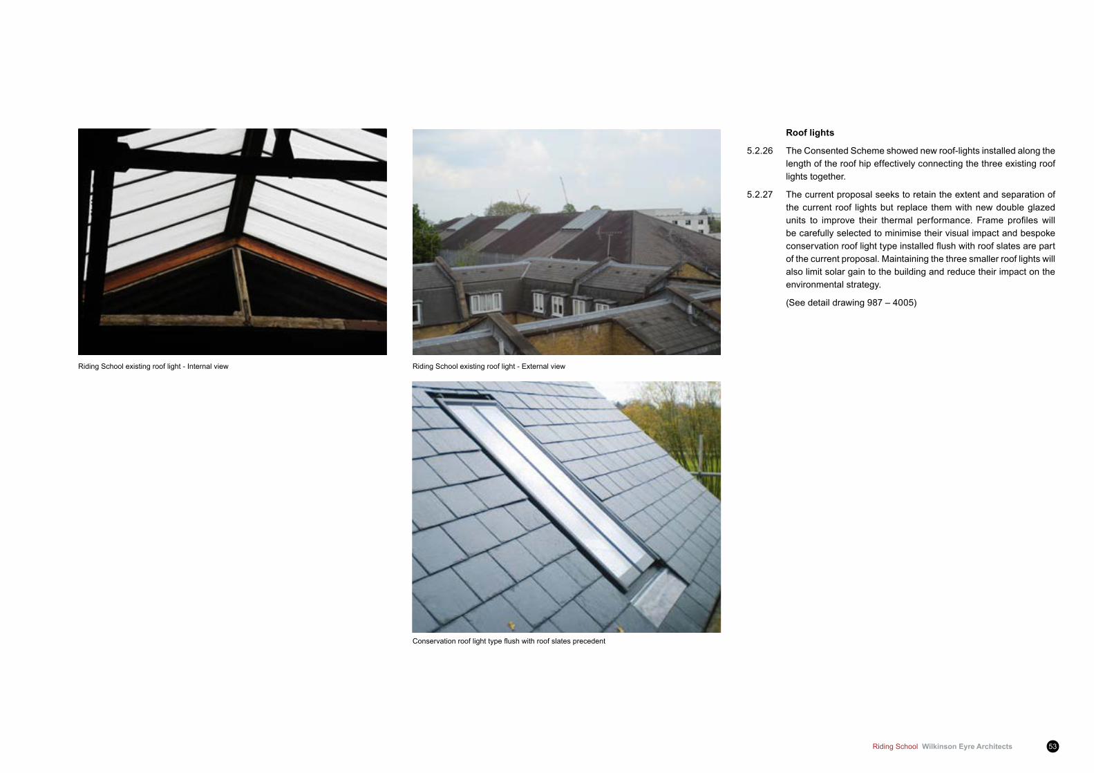
Roof lights
5.2.26 The Consented Scheme showed new roof-lights installed along the length of the roof hip effectively connecting the three existing roof lights together.
5.2.27 The current proposal seeks to retain the extent and separation of the current roof lights but replace them with new double glazed units to improve their thermal performance. Frame profileswillbe carefully selected to minimise their visual impact and bespoke conservationrooflighttypeinstalledflushwithroofslatesarepartof the current proposal. Maintaining the three smaller roof lights will also limit solar gain to the building and reduce their impact on the environmental strategy.
(See detail drawing 987 – 4005)
Riding School existing roof light - Internal view
Conservationrooflighttypeflushwithroofslatesprecedent
Riding School existing roof light - External view

Wilkinson Eyre Architects Riding School54
5 Material and fabrics
Timber roof cleaning samples
5.3 Interior fabric proposal5.3.1 Theinteriorof theRidingSchool isperhapsthemostsignificant
feature of the building. The distinctive combination of the timber trusses, the white painted walls and black painted battered timber panelling will be retained.
5.3.2 A number of cleaning samples were undertaken to ascertain the condition of the interior; these were of great value to inform the development of the design proposal for the interior spaces.
5.3.3 The following cleaning techniques were used:
Roof trusses
Cleaning sample:
5.3.4 All roof members had all been coated in a lime based coating; the existing lime coatings were carefully removed using a low pressure compressed air blasting system to rejuvenate the timber surface to its original surface. The approach was sensitive in nature to the finishedsurfaceof the timberandsuccessfully rejuvenated thetimber to its original splendour.
Proposal:
5.3.5 It is proposed to remove the lime based coating to all roof members and recommend the application of special breathable treatment to the timber to maintain and enhance the natural colour and depth of the material. The product will be carefully researched and tested to ensure it will not have an adverse reaction with any airborne chemicals it may be in contact following the installation of the pool.
Metal support straps to truss chord
Cleaning sample:
5.3.6 The lime wash coatings and rust were carefully and effectively removed using the same cleaning technique applied to the timber trusses
Proposal:
5.3.7 It is proposed to remove the lime based coating to all metal straps to truss chord and recommended to retain the patina with the application of hard wearing rust inhibitor to prevent surface rust from reappearing.

Riding School Wilkinson Eyre Architects 55
Existing timber paneling cleaning samples
Existing internal wall cleaning samples
Painted brickwork
Cleaning sample:
5.3.8 Initial observation and test made apparent that the brickwork walls have been coated with a modern acrylic coating on top of the original lime wash. The brickwork was carefully cleaned using a chemical strip and subsequent steam clean application.
Proposal:
5.3.9 It is proposed to clean the brickwork wall all along the interior of the building and re-apply a breathable lime wash as per original appearance.
Timber panelling
Cleaning sample:
5.4.0 The dark coating of the timber panelling was carefully removed with the use of a specialist paint softener, the surface was then treated with a steam clean application
Proposal:
5.4.1 It is proposed to clean and remove the existing coating and paint from the existing panelling; further tests will need to be carried out to ascertain the nature of the existing black paint to make sure it does not consist of any hazardous material.
5.4.2 The timber panelling will be refurbished and restored and a new black coating paint will be applied to reinstate the original appearance; the zone behind the panelling will typically be used to conceal the supply air plenum to both the Pool and Residents’ lobby. The existing pattern of vent holes in the timber panelling may also be used and extended to assist with this strategy, additional elegant metal grilles may be introduced should this be required to meet the ventilation air supply requirement, although not envisaged at this stage. The zone behind the timber panelling will also accommodate a layer of high performance insulation to improve the thermal performance of the external walls in this location.
5.4.3 In addition to improvements to the building envelope some other works to the existing fabric will also be required. Within the pool spaceallexistingmetalfixtures,fittingsandfixingswillneedtobereplaced using the correct grade of stainless steel or treated with specialist products to ensure they do not corrode as a consequence of the pool environmental conditions and the chemical treatment required to maintain the water quality.
5.4.4 Any internal elements of the building that are of no historical significance,suchasredundantmechanicalandelectricalsystems,will be removed.
Wilkinson Eyre Architects Riding School56
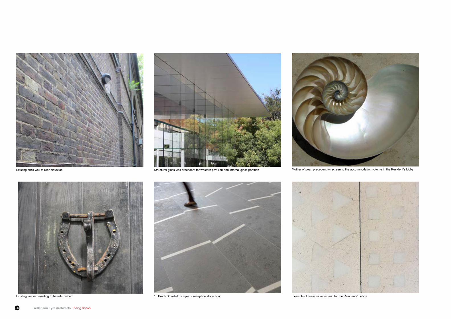
Existing brick wall to rear elevation
Existing timber panelling to be refurbished
Structural glass wall precedent for western pavillion and internal glass partition
10BrockStreet–Exampleofreceptionstonefloor
Mother of pearl precedent for screen to the accommodation volume in the Resident’s lobby
Example of terrazzo veneziano for the Residents’ Lobby
Riding School Wilkinson Eyre Architects 57
Theme Rationale Materials Possible Location/s
Lightness To contrast with the solidity of the building’s brick construction.
Low iron glass
Structural glass construction
Glass partition
Western Pavilion
Translucency To contrast with the solidity of the building’s brick construction.
Fritted glass Glass partition
Iridescence To give a sense of luxury and elegance.
Dichroicfilmtoglass
Pre-patinated metal
Fabric
Screen to the enclosed volume within the Riding School
Soft furnishings
Classical Toreflecttheclassical/Italianate style of the existing building.
Terrazzo
Natural stone
Flooring
Military Toreflectthehistory of the building and the site.
Riveted metal panelling
Cladding to the enclosed volume within the Riding School
MetalcladdingprecedentforGroundfloorandMezzanineenclosure
Iridescent material precedent
1.1 Table proposed material selection
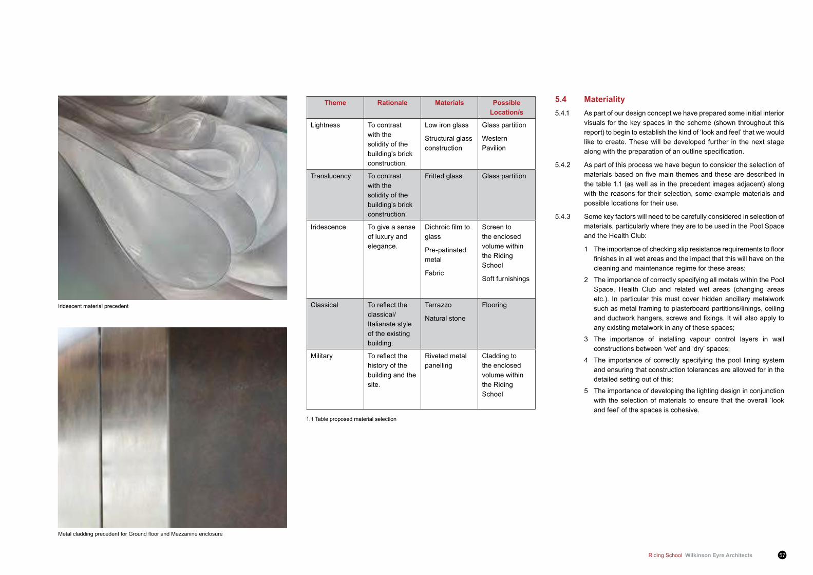
5.4 Materiality5.4.1 As part of our design concept we have prepared some initial interior
visuals for the key spaces in the scheme (shown throughout this report) to begin to establish the kind of ‘look and feel’ that we would like to create. These will be developed further in the next stage alongwiththepreparationofanoutlinespecification.
5.4.2 As part of this process we have begun to consider the selection of materialsbasedonfivemainthemesandthesearedescribedinthe table 1.1 (as well as in the precedent images adjacent) along with the reasons for their selection, some example materials and possible locations for their use.
5.4.3 Some key factors will need to be carefully considered in selection of materials, particularly where they are to be used in the Pool Space and the Health Club:
1 Theimportanceofcheckingslipresistancerequirementstofloorfinishesinallwetareasandtheimpactthatthiswillhaveonthecleaning and maintenance regime for these areas;
2 The importance of correctly specifying all metals within the Pool Space, Health Club and related wet areas (changing areas etc.). In particular this must cover hidden ancillary metalwork such as metal framing to plasterboard partitions/linings, ceiling andductworkhangers,screwsandfixings.Itwillalsoapplytoany existing metalwork in any of these spaces;
3 The importance of installing vapour control layers in wall constructions between ‘wet’ and ‘dry’ spaces;
4 The importance of correctly specifying the pool lining system and ensuring that construction tolerances are allowed for in the detailed setting out of this;
5 The importance of developing the lighting design in conjunction with the selection of materials to ensure that the overall ‘look and feel’ of the spaces is cohesive.
Wilkinson Eyre Architects Riding School58
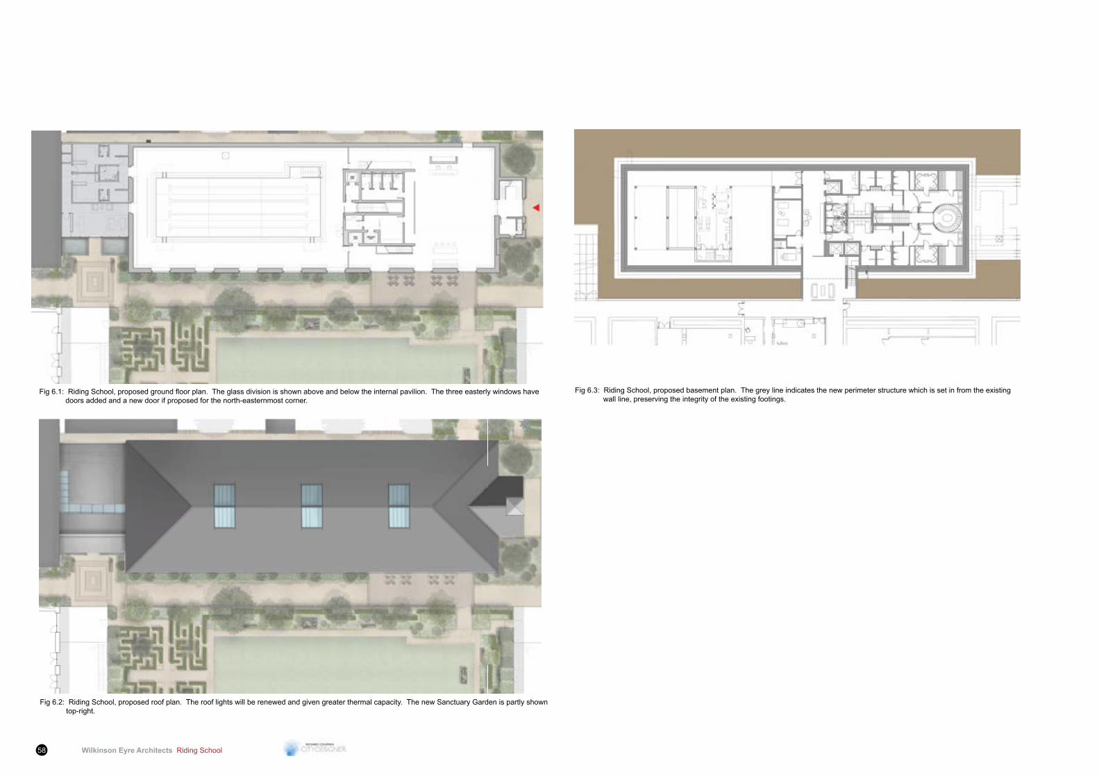
Fig6.1:RidingSchool,proposedgroundfloorplan.Theglassdivisionisshownaboveandbelowtheinternalpavilion.Thethreeeasterlywindowshave doors added and a new door if proposed for the north-easternmost corner.
Fig 6.2: Riding School, proposed roof plan. The roof lights will be renewed and given greater thermal capacity. The new Sanctuary Garden is partly shown top-right.
Fig 6.3: Riding School, proposed basement plan. The grey line indicates the new perimeter structure which is set in from the existing wall line, preserving the integrity of the existing footings.

Riding School Wilkinson Eyre Architects 59
6 Heritage impact assessment
This chapter is an extract from Richard Coleman Citydesigner’s ‘The Riding School – Heritage and Alteration Assessment’ report and provides the design assessment of the Riding School.
6.0.1 The project builds upon the Consented Scheme for a swimming pool and supporting internal structures. The new use was approved in principal without fully worked out details. The Proposed Development has now been fully worked through into detail based on the particular vision of the Applicant and the inspired new setting and public thoroughfares conceived by Squire and Partners.
6.0.2 A further inspiration has been the commissioning of Wilkinson Eyre Architects for the detailed design work for the listed Riding School. Not only is this practice world renowned for their work, but principal partner Jim Eyre is connected with the Eyre Estate who recently sold the Barracks site. Jim Eyre is taking part in the design work required to give the Riding School a new and sustainable use.
6.0.3 The proposal is illustrated in the following drawings. The alterations are carefully tempered to the necessities of the new use, the sustainability of the building long term, and the enhancement of it both internally, externally, and of its setting. First, therefore, its enhanced setting needs to be explained.
6.0.4 The existing setting is poor, having been the consequence of frequent changes to the Barracks layout and updated buildings. The only meaningful nature of its immediate, rather cramped, setting is the fact that the most adjacent buildings were for stabling, connecting the horse use to the Riding School. The proposed Squire and Partners setting consists of a new public route across the Main Site which passes alongside the Riding School building and beyond which is a ‘London Square’ garden related to the residential buildings which surround the other three sides. The poor buildings attached to the west of the Riding School would be replaced by a reception and changing rooms building for public use, designed by Wilkinson Eyre, and to the east the setting of the main entrance would be expanded with a new square, to receive vehicular arrivals.
6.0.5 The strong desire to give the Riding School a worthy connectivity to its new setting has brought about the concept of both visual and pedestrian permeability through the south wall. The early drawings oftheSchoolpriortoitsconstruction(seefigure3.13)showedarchedwindows down to the ground, rather like an ‘Orangery’. Naturally, as the original design was developed, it became necessary for the sills of the windows to be lifted in order for the horses not to be distracted by activity outside. A new use for the building, without the involvement of horses, no longer needs this facility and it is intended to drop the sills somewhat like the original drawing. This will enable
a more permeable wall giving a strong relationship with the garden and, at the eastern end, door access to the function room end of the building. Elsewhere, the dropped windows would provide recessed benchseatingusingthemodifiedtimberwainskirtingasalinertocomplement the swimming pool use. An important factor has been to ensure that such an alteration maintains the repetitive nature ofthewindows,oneoftheprincipalfeaturesofsignificance,bothexternally and internally.
6.0.6 A major proposition is to return the external surface of the building back to brick where it has been rendered. Not only has the render been wrongly applied with a cementitious mix but its being impervious to moisture has put the fabric at risk. Certainly this risk of long term deterioration to the fabric would increase with the new uses, which require heating and moisture control, unless a more breathable surface is given to the external surface. Through studies, it has become clear that the existing depth of masonry issufficientnot torequire insulation.Had itnotbeenthecaseanew rendered surface may have been the best solution. Without that requirement, removing the render to reveal the brick has been investigated. But the hardness of the render means that attempting to remove it tears away the surface of the brick. It is possible, however, to introduce a new skin of brickwork to return the building toitsoriginalappearance.Thiswouldnotbesuperficialbutbuiltintothe remaining brickwork so that the new and the old act together structurally. Experiments will be carried out in order to ensure that a close match with the historic brick is found and constructed. A rendered solution using a breathable material remains a solution. The final treatment of the facade is to be controlled through acondition attached to the Listed Building Consent, with the potential for re-rendering of the facade to be secured.
6.0.7 Other external changes would be subtle. The windows would be refurbished and sealed double glazed glazing would be inserted. Wherethermalcapacitywouldbebeneficialisintheroof.Inwishingto leave undisturbed the internal timber boarding above the rafters, the proposal is to insulate from above between new purlins and to effectively raise the roof surface by the minimum required amount. Thiswouldmeancreatinganewcorbelledeavesprofileaspartof the renewed external brickwork. Clocks would be added to the existing clock housing so that visitors from all directions are greeted appropriately while maintaining the one which historically faced the Barracks. The main entrance would receive a glazed outer door screen and the upper lunette window above it, which is plastic, would be replaced with a timber version.
6.0.8 Internally the principal space would be divided environmentally though not visually. A glass screen would be erected between the
third and fourth window bay closest to the entrance, parallel to the trusses.Itwouldbeofclearwhitenon-reflectiveglassinextralargepanels with minimal detail and made to be reversible. The pool and its ancillary equipment would be cut into a new basement level. At the entrance end, a new reception area would provide immediate and extensive views of the great roof, which would remain unchanged except for some tidying up and cleaning. Before the screen would be a pavilion of accommodation with a deck above. This would provide the sanitary and catering facilities, and access to the basement level.Aswellasthefirstthreewindowsprovidingdooraccesstothecentralgarden,beneaththefirstlunettebayonthenorthsidewould be a new door to a meditative garden landscape. Where the windows are lowered, the perimeter timber wainskirting would be trimmed and returned into the opening to accommodate the doors, or with a similar detail to accommodate a bench. Ventilation systems would be incorporated into the wainskirting construction.
6.0.9 The Sanctuary Garden to be created on land at the rear of the Riding School and which interacts with it in terms of connectivity would contribute to the place-making throughout the Main Site and would enhance the setting of the listed building.
6.0.10 A great deal of study has been put into the environmental conditions arising from enclosing the building, its main access way never having had doors, and the consequences of installing a swimming pool. Atellier 10, a leading Environmental Engineering Consultancy, has studied the building and recommended certain safeguards which involve the ‘breathability’ of the structure, the appropriate insulation and the adequacy of air movement.
6.0.11 The design work overall has been carefully considered and thought through into the detail. At every stage consideration has been given tothespecialsignificanceofthebuildingasadesignatedheritageasset in such a way as to enhance the building, sustain its life, and make it into a publicly available local landmark and leisure facility. While there is some inevitable loss of listed fabric, this has been kept to a minimum and is more than balanced by the commodity provided to the residents and the public.
‘For a detailed report on the heritage assessment please see ‘The Riding School – Heritage and Alteration Assessment’ document.

Wilkinson Eyre Architects Riding School60
6 Heritage Impact Assessment
Fig 6.4: Riding School, proposed south-east elevation. The rigor of the original design is maintained while all the windows are lowered for visual and pedestrian permeability. In particular, the three right hand windows are to include doors.Thepresentrenderisreplacedwithnew,carefullychosenandconstructedbrickworktoemulatetheoriginalcondition.Thelefthandextensionisaminimalist,refineddesignoflessvolumethanthatwhichitreplaces, thus giving the building greater architectural presence.
Fig 6.5: Riding School, proposed long section. This shows the entry sequence from the right and the wide angle of view now possible of the roof (compared to the approved scheme). The basement structure is kept well away from the existing walls. A minimal amount of ducting is proposed within the roof construction above the pool area. The extended upper room is shown as a glazed volume.
Riding School Wilkinson Eyre Architects 61
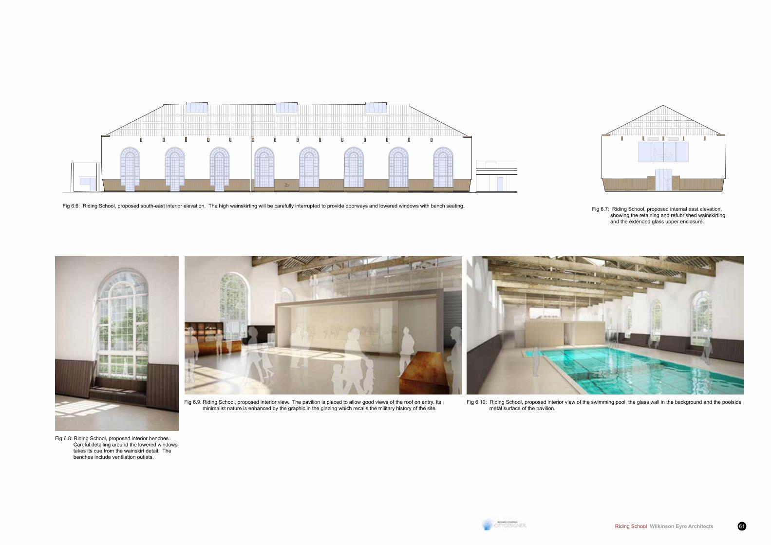
Fig 6.6: Riding School, proposed south-east interior elevation. The high wainskirting will be carefully interrupted to provide doorways and lowered windows with bench seating. Fig 6.7: Riding School, proposed internal east elevation, showing the retaining and refubrished wainskirting and the extended glass upper enclosure.
Fig 6.8: Riding School, proposed interior benches. Careful detailing around the lowered windows takes its cue from the wainskirt detail. The benches include ventilation outlets.
Fig 6.9: Riding School, proposed interior view. The pavilion is placed to allow good views of the roof on entry. Its minimalist nature is enhanced by the graphic in the glazing which recalls the military history of the site.
Fig 6.10: Riding School, proposed interior view of the swimming pool, the glass wall in the background and the poolside metal surface of the pavilion.

Wilkinson Eyre Architects Riding School62
Proposed Landscape Masterplan - Andy Sturgeon Landscape Design
Riding School Wilkinson Eyre Architects 63
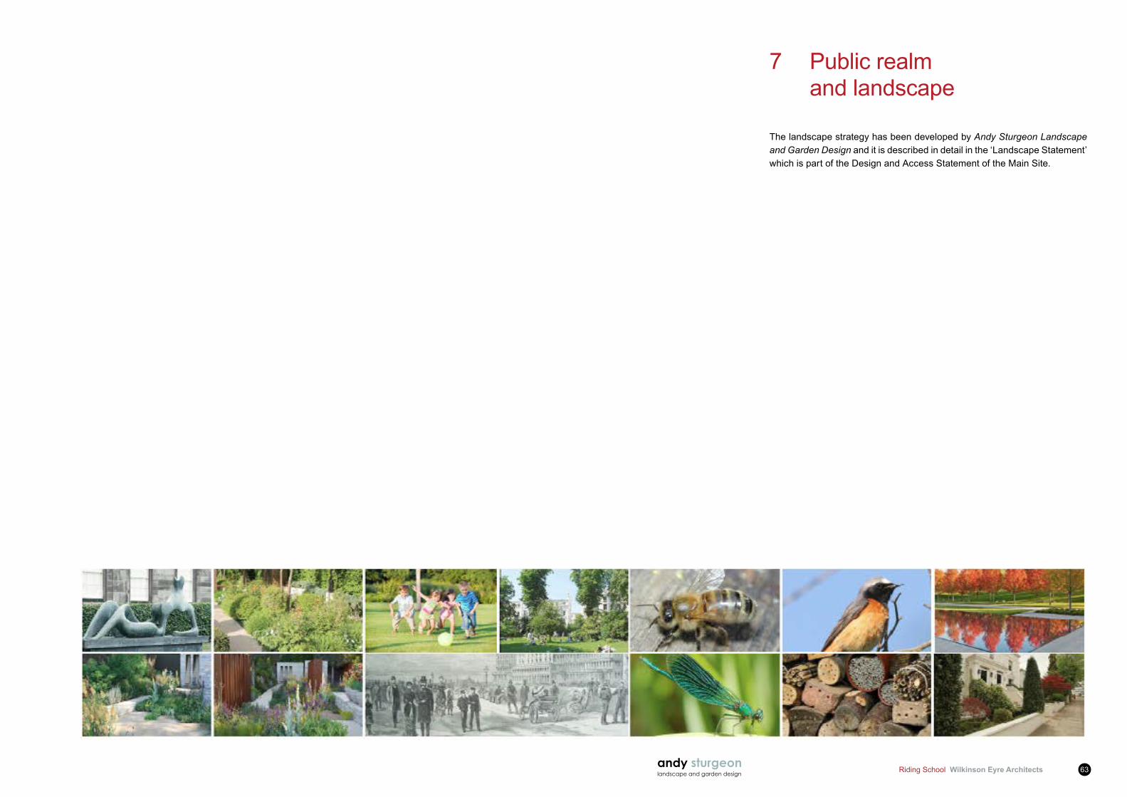
7 Public realm and landscape
The landscape strategy has been developed by Andy Sturgeon Landscape and Garden Design and it is described in detail in the ‘Landscape Statement’ which is part of the Design and Access Statement of the Main Site.
andy sturgeonlandscape and garden design
St. Johns Wood Square
Landscape Development Report 1
23rd May 2014
Andy Sturgeon Landscape and Garden Design, 20 Clermont Road, Brighton, East Sussex, BN1 6SG
www.andysturgeon.com [email protected] 01273 553336
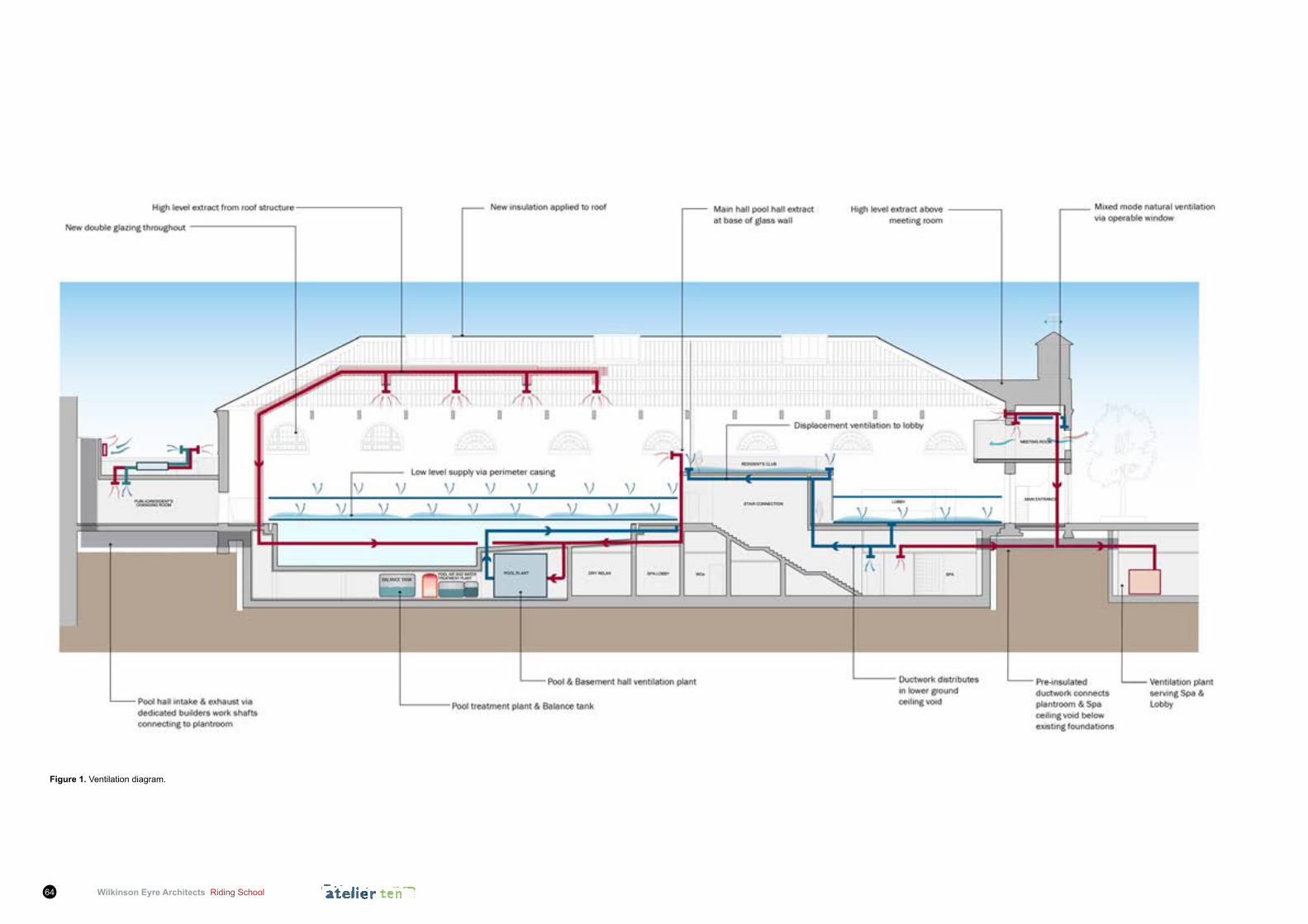
Wilkinson Eyre Architects Riding School64
figure 1. Ventilation diagram.
Riding School Wilkinson Eyre Architects 65
8.1 Sustainability Implementation Plan (SIP)8.1.1 Sustainability lies at the core of the St. John’s Wood Square
Project as a whole. By adopting a sustainable approach to design, construction and operation, the St. John’s Wood Square Project aims to establish itself as an exemplary sustainable development, meet the Applicant’s aspirations, satisfy the requirements of the local planning policy to achieve Code Level 4 and exceed the Building Regulations standards, wherever it is technically, functionally and economically feasible.
8.1.2 Sustainability is embedded in the project’s vision: “to create and, by preference retain, a superlative residential destination oriented to a family lifestyle rooted in the unique environment of St John’s Wood”.HealthandwellbeinghavebeenidentifiedbytheApplicantas a key ambition for the project.
8.1.3 ThisisreflectedthroughouttheSustainabilityImplementationPlan(SIP). This document elaborates on the ambitions of the project, sets out commitments, where possible, and areas for further work in design development, and identifies some of themethods bywhich the ambition of a sustainable approach will be maintained and ensured in the delivery of the project.
8.1.4 The SIP is also intended to act as a sustainability manifesto for the development going forwards, to help envisage how it can be, not just better than normal, but provide a catalyst for change to the way a sustainable urban development can be implemented.
8.1.5 It is a principal requirement of the Masterplan that the design, construction and operation stages of a project integrate sustainable practices from the outset. The SIP offers an integrated approach to the incorporation of sustainable principles and practices into the development and an effective way to ensure that the highest possible sustainable targets are met within the technical and financialconstraintsofthisproject.
8.1.6 The purpose of the SIP is to provide guidelines for the design team, contractors and wider stakeholders to assist in the development and delivery of sustainability across the Proposed Development. The SIP looks at the two predominant building types for the proposed site: residential and health club. The aim of the SIP is to fuse the requirements and strategies of planning policy, benchmarking and Applicant’s brief to advocate sustainability throughout the entire programme of works.
8.1.7 This document is broken down into a number of thematic areas encompassing different aspects of the environment that the development impacts. These are as follows:
8 Sustainability, Energy strategy and Building Services
• Energy & CO2 Emissions
• Water
• Materials
• Waste
• Pollution
• Health & Wellbeing
• Management
• Ecology & Land Use
• Transport
8.1.8 The key strategies proposed and/or recommended for the Riding School in the Proposed Development are summarised in the following sections under each environmental issue.
8.1.9 For the full version of the SIP document, refer to the St. John’s Wood Square – Sustainability and Energy Statement.
8.2 Energy & CO2 Emissions8.2.1 The Riding School building will be designed to minimise the CO2
emissions associated with its operational energy consumption.
8.2.2 For a full description of the energy strategy proposed for the Riding School, refer to section 8.11 Energy Strategy.
8.3 Water8.3.1 The Proposed Development will minimise the consumption of
potable water in sanitary applications and for landscape irrigation.
8.3.2 Lowwaterusefixturesandfittingswillbeinstalledinthebuilding.Fittings,suchasflowrestrictors,willbefittedtotapsandpotentiallyshowerheads.WCswillbeprovidedwithdualflushcisternsandfittedwithdelayedactioninletvalves.
8.3.3 Rainwater recycling will be implemented in the development for the purpose of irrigation of landscaping. Rainwater will be harvested from appropriate hard outdoor surfaces, including roof catchment areas. Rainwater will be stored in suitably sized tanks located in the plant rooms at basement level.
8.3.4 A low-water irrigation strategy will be adopted in the Development.
8.3.5 A water meter with a pulsed output to enable connection to a Building ManagementSystem(BMS)willbespecifiedonthemainswatersupply to the Development. Additional sub-meters of the same type willbefittedonthesupplytoindividualwater-consumingplantsorbuilding areas. This metering strategy will ensure water consumption can be monitored and managed, therefore encouraging reductions in water consumption.
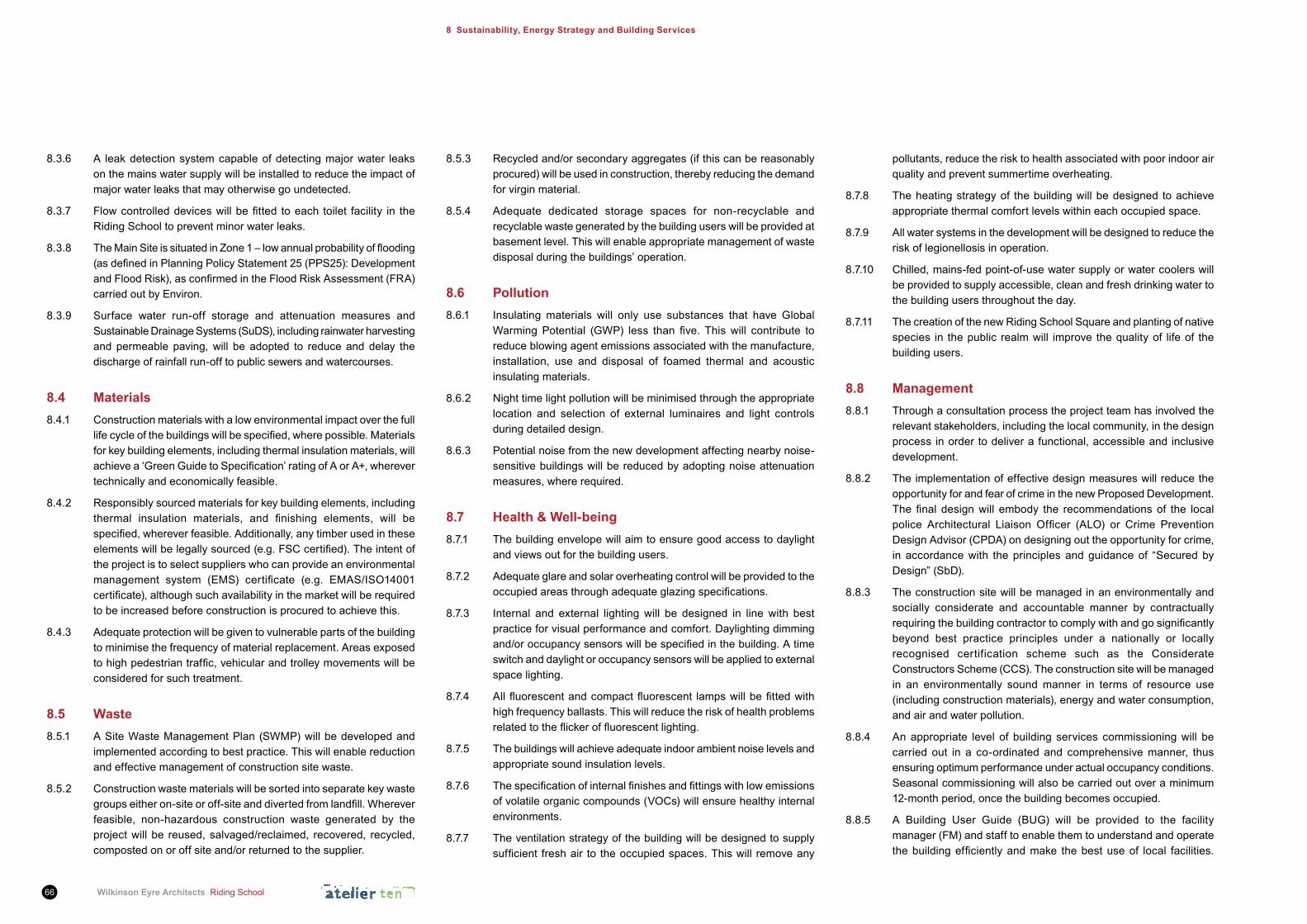
Wilkinson Eyre Architects Riding School66
8 Sustainability, Energy Strategy and Building Services
8.5.3 Recycled and/or secondary aggregates (if this can be reasonably procured) will be used in construction, thereby reducing the demand for virgin material.
8.5.4 Adequate dedicated storage spaces for non-recyclable and recyclable waste generated by the building users will be provided at basement level. This will enable appropriate management of waste disposal during the buildings’ operation.
8.6 Pollution8.6.1 Insulating materials will only use substances that have Global
WarmingPotential (GWP) less than five. Thiswill contribute toreduce blowing agent emissions associated with the manufacture, installation, use and disposal of foamed thermal and acoustic insulating materials.
8.6.2 Night time light pollution will be minimised through the appropriate location and selection of external luminaires and light controls during detailed design.
8.6.3 Potential noise from the new development affecting nearby noise-sensitive buildings will be reduced by adopting noise attenuation measures, where required.
8.7 Health & Well-being8.7.1 The building envelope will aim to ensure good access to daylight
and views out for the building users.
8.7.2 Adequate glare and solar overheating control will be provided to the occupiedareasthroughadequateglazingspecifications.
8.7.3 Internal and external lighting will be designed in line with best practice for visual performance and comfort. Daylighting dimming and/oroccupancysensorswillbespecifiedinthebuilding.Atimeswitch and daylight or occupancy sensors will be applied to external space lighting.
8.7.4 Allfluorescentandcompactfluorescent lampswillbefittedwithhigh frequency ballasts. This will reduce the risk of health problems relatedtotheflickeroffluorescentlighting.
8.7.5 The buildings will achieve adequate indoor ambient noise levels and appropriate sound insulation levels.
8.7.6 Thespecificationofinternalfinishesandfittingswithlowemissionsof volatile organic compounds (VOCs) will ensure healthy internal environments.
8.7.7 The ventilation strategy of the building will be designed to supply sufficient freshair to theoccupiedspaces.Thiswill removeany
pollutants, reduce the risk to health associated with poor indoor air quality and prevent summertime overheating.
8.7.8 The heating strategy of the building will be designed to achieve appropriate thermal comfort levels within each occupied space.
8.7.9 All water systems in the development will be designed to reduce the risk of legionellosis in operation.
8.7.10 Chilled, mains-fed point-of-use water supply or water coolers will be provided to supply accessible, clean and fresh drinking water to the building users throughout the day.
8.7.11 The creation of the new Riding School Square and planting of native species in the public realm will improve the quality of life of the building users.
8.8 Management8.8.1 Through a consultation process the project team has involved the
relevant stakeholders, including the local community, in the design process in order to deliver a functional, accessible and inclusive development.
8.8.2 The implementation of effective design measures will reduce the opportunity for and fear of crime in the new Proposed Development. Thefinaldesignwill embody the recommendationsof the localpolice Architectural Liaison Officer (ALO) or Crime PreventionDesign Advisor (CPDA) on designing out the opportunity for crime, in accordance with the principles and guidance of “Secured by Design” (SbD).
8.8.3 The construction site will be managed in an environmentally and socially considerate and accountable manner by contractually requiringthebuildingcontractortocomplywithandgosignificantlybeyond best practice principles under a nationally or locally recognised certification scheme such as the Considerate Constructors Scheme (CCS). The construction site will be managed in an environmentally sound manner in terms of resource use (including construction materials), energy and water consumption, and air and water pollution.
8.8.4 An appropriate level of building services commissioning will be carried out in a co-ordinated and comprehensive manner, thus ensuring optimum performance under actual occupancy conditions. Seasonal commissioning will also be carried out over a minimum 12-month period, once the building becomes occupied.
8.8.5 A Building User Guide (BUG) will be provided to the facility manager (FM) and staff to enable them to understand and operate thebuildingefficientlyandmake thebestuseof local facilities.
8.3.6 A leak detection system capable of detecting major water leaks on the mains water supply will be installed to reduce the impact of major water leaks that may otherwise go undetected.
8.3.7 Flowcontrolleddeviceswillbefitted toeach toilet facility in theRiding School to prevent minor water leaks.
8.3.8 TheMainSiteissituatedinZone1–lowannualprobabilityofflooding(asdefinedinPlanningPolicyStatement25(PPS25):DevelopmentandFloodRisk),asconfirmedintheFloodRiskAssessment(FRA)carried out by Environ.
8.3.9 Surface water run-off storage and attenuation measures and Sustainable Drainage Systems (SuDS), including rainwater harvesting and permeable paving, will be adopted to reduce and delay the discharge of rainfall run-off to public sewers and watercourses.
8.4 Materials8.4.1 Construction materials with a low environmental impact over the full
lifecycleofthebuildingswillbespecified,wherepossible.Materialsfor key building elements, including thermal insulation materials, will achievea‘GreenGuidetoSpecification’ratingofAorA+,wherevertechnically and economically feasible.
8.4.2 Responsibly sourced materials for key building elements, including thermal insulation materials, and finishing elements, will bespecified,whereverfeasible.Additionally,anytimberusedintheseelementswillbelegallysourced(e.g.FSCcertified).Theintentofthe project is to select suppliers who can provide an environmental management system (EMS) certificate (e.g. EMAS/ISO14001certificate),althoughsuchavailabilityinthemarketwillberequiredto be increased before construction is procured to achieve this.
8.4.3 Adequate protection will be given to vulnerable parts of the building to minimise the frequency of material replacement. Areas exposed tohighpedestriantraffic,vehicularandtrolleymovementswillbeconsidered for such treatment.
8.5 Waste8.5.1 A Site Waste Management Plan (SWMP) will be developed and
implemented according to best practice. This will enable reduction and effective management of construction site waste.
8.5.2 Construction waste materials will be sorted into separate key waste groupseitheron-siteoroff-siteanddivertedfromlandfill.Whereverfeasible, non-hazardous construction waste generated by the project will be reused, salvaged/reclaimed, recovered, recycled, composted on or off site and/or returned to the supplier.

Riding School Wilkinson Eyre Architects 67
This non-technical and simple user guide will cover information on the operation and environmental performance of the building and information relating to the site and its surroundings.
8.9 Ecology & Land Use8.9.1 The Proposed Development’s footprint will be on an area of land
which has been previously developed. In particular, the listed Riding School is an existing building, which will be converted into a health club.
8.9.2 The Main Site has mostly low ecological value, as stated in the ecology report undertaken by Environ.
8.9.3 The ecological value of the Site will be enhanced as a result of Development. The recommendations included in an ecological assessment for enhancement of the site ecology will be implemented.
8.9.4 The long-term impact of the development on the biodiversity of the site and surrounding area will be minimised.
8.10 Transport8.10.1 The building will be located in proximity to an excellent public
transport network, thus reducing transport-related emissions and trafficcongestion.
8.10.2 The building will also be located in proximity to local amenities, thereby reducing the need for extended travel or multiple trips.
8.10.3 The site layout will be designed in order to provide safe and secure pedestrian and cycle access routes within the Proposed Development.
8.10.4 A well-planned site layout and access to the Main Site will also ensure that safety is maintained during deliveries and manoeuvring, and disruption due to delivery vehicles minimised.
8.10.5 A green travel plan based on a site-specific travel survey/assessment will be developed to accommodate a range of travel options for building users, thereby encouraging the reduction of user reliance on forms of travel that have the highest environmental impact.
8.11 Energy Hierarchy8.11.1 The Proposed Development aims to minimise CO2 emissions to the
atmosphere arising from the operations of, and within, the buildings.To minimise CO2 emissions, the following energy hierarchy has been applied to the design strategy of the Proposed Development:
• minimising energy consumption through passive design measures;
• supplyingenergyefficientlythroughactivesystems;and
• maximising energy generation from renewable sources.
8.11.2 The three principles outlined above have been applied in sequence and systematically in the development of the proposal for the Riding School. These are illustrated in the following sections.
8.12 Passive Design Measures8.12.1 TheenergyefficientbuildingdesignoftheproposedRidingSchool
development will minimise the need for energy in operation while maximising the comfort of users during the lifetime of the building. The integration of passive design principles will enable the building to be less reliant on heating, ventilation and air conditioning (HVAC) systems andminimize dependence on artificial lighting, takingadvantageofnaturalenergyflowstomaintainthermalcomfort.
8.12.2 To limit heat losses across the building envelope a number of measureshavebeen implemented.These includeefficienthighlevels of insulation and airtightness in the new extension and upgrade of the building fabric of the existing building. In particular, theexistingwindowsandrooflightswillbereplacedwithdoubleglazing units and insulation will be provided to the roof to prevent condensation, reduce heating loads in winter and maintain comfortable indoor environments.
8.12.3 The location of most of the new extension underground allows to minimise the exposed areas of the building envelope and, therefore, the heat loss through the fabric in winter and solar heat gain through the fabric in summer.
8.12.4 The building envelope of the new extension will be compliant with the Building Regulations Part L 2013 standards, as described in the Approved Document L2A (ADL2A) 2013 (“Conservation of fuel and power in new buildings other than dwellings”), and go beyond the limiting U-values and design air permeability set out in the ADL2A 2013.
8.12.5 The building envelope of the existing building will be compliant with the Building Regulations Part L 2013 standards, as described in the Approved Document L2B (ADL2B) 2013 (“Conservation of fuel and power in existing buildings other than dwellings”), and meet the requirements for consequential improvements set out in the ADL2B2013,whereveristechnicallyorfinanciallyviableoritdoesnot create condensation risk or impact on the character of the listed building.
8.13 EnergyEfficientSystems8.13.1 The majority of the supplied energy will be used to operate the
building.ByimprovingtheenergyefficiencyofHVACanddomestichot water (DHW) systems, lighting, appliances and equipment the need for energy in operation during the lifetime of the buildings will be minimised.
Energy Supply
8.13.2 The Riding School will be served from site-wide heating, cooling and DHW systems with network separation via plate heat exchangers. Flow and return connections for space heating, cooling and DHW willberoutedtoa lowergroundfloorplantroom.Thepoolwatertreatment and pool hall ventilation plants will be located in a plantroom underneath the pool hall. The ventilation plant serving the lobby, spa and lower ground changing room area will be located inalowergroundfloorplantroomtotheeastoftheRidingSchool.
8.13.3 For further details on the site-wide systems, refer to the St. John’s Wood Square - Sustainability and Energy Statement.
HVAC & DHW Systems
8.13.4 Heat will be supplied to all areas of the health club, including the poolhall,throughawetunderfloorheatingsystem.Suchasystemwillmeetthespecificrequirementsofflexibilityandthermalcomfortof the occupants typical of this building type and compatibility with the low temperature from the very low temperature hot water (VLTHW) circuit coming from the main network.
8.13.5 Chilled water will be supplied to ceiling mounted fan coil units (FCUs) in the new extension of the Riding School and air handling units (AHUs) in the Riding School plantrooms.
8.13.6 DHWwillbeprovidedviacalorifiers located inthe lowergroundplantroom and to the pool water treatment plant located underneath the pool hall.
8.13.7 Heating to the pool hall will be supplied through the mechanical ventilation system, which will also remove airborne contaminants and provide dehumidification.Heated fresh air will be suppliedfrom the existing perimeter timber casing at low level, acting as a plenum, directly to the occupied zone at low velocity. Temperature and humidity will allow to modulate the amount of fresh air supply to the pool hall. A three-way mixing box installed on the inlet of the pool hall AHU will allow air to be re-circulated. Exhaust air will be extracted at the base of the glass partition at mezzanine level and at high level from a duct routed beneath the roof structure. This will ensure that moist air will not collect around the existing roof structure. Such a ventilation system will ensure good air quality
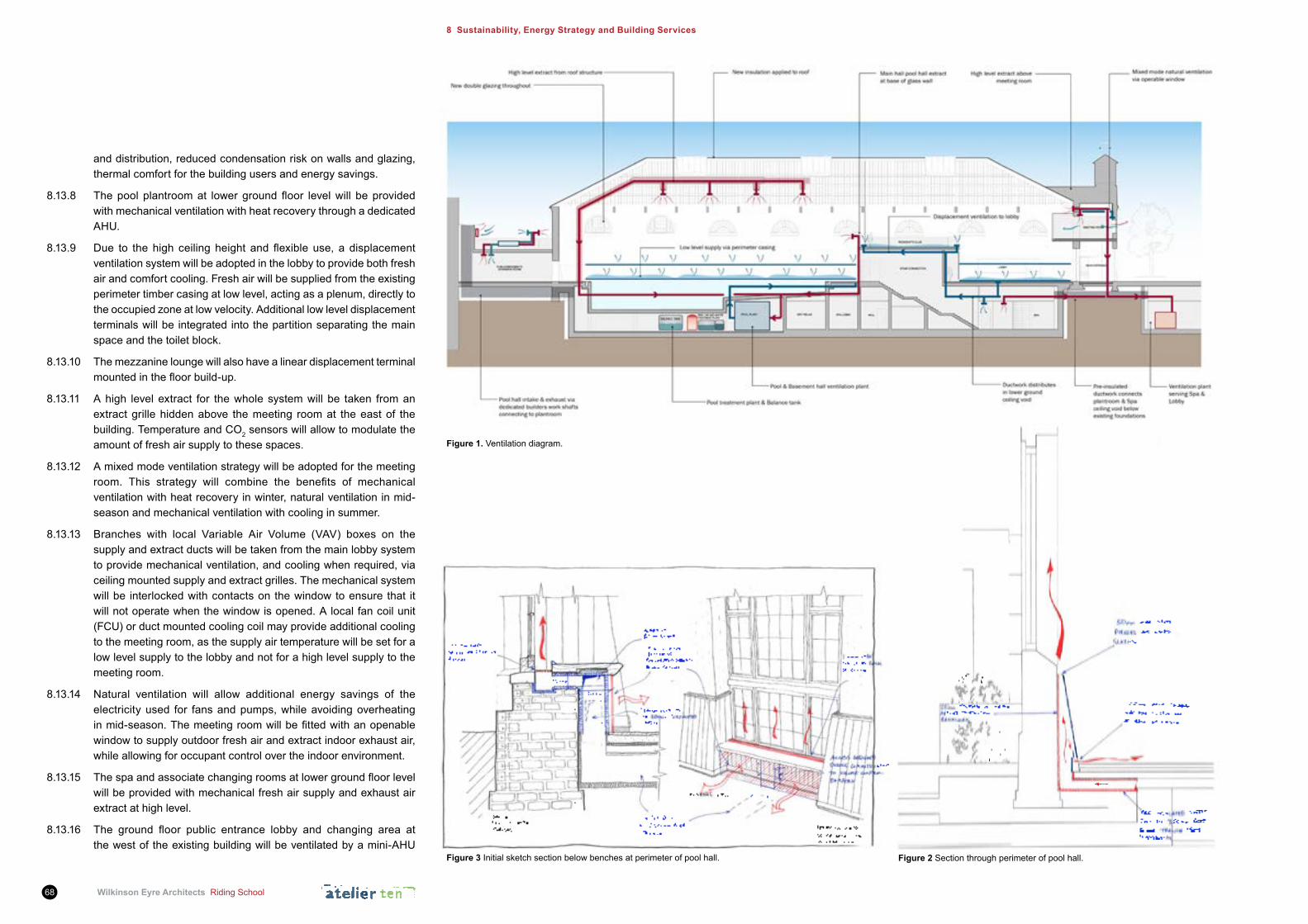
Wilkinson Eyre Architects Riding School68
8 Sustainability, Energy Strategy and Building Services
and distribution, reduced condensation risk on walls and glazing, thermal comfort for the building users and energy savings.
8.13.8 Thepoolplantroomat lowergroundfloor levelwill beprovidedwith mechanical ventilation with heat recovery through a dedicated AHU.
8.13.9 Due to thehigh ceilingheight and flexible use, a displacementventilation system will be adopted in the lobby to provide both fresh air and comfort cooling. Fresh air will be supplied from the existing perimeter timber casing at low level, acting as a plenum, directly to the occupied zone at low velocity. Additional low level displacement terminals will be integrated into the partition separating the main space and the toilet block.
8.13.10 The mezzanine lounge will also have a linear displacement terminal mountedinthefloorbuild-up.
8.13.11 A high level extract for the whole system will be taken from an extract grille hidden above the meeting room at the east of the building. Temperature and CO2 sensors will allow to modulate the amount of fresh air supply to these spaces.
8.13.12 A mixed mode ventilation strategy will be adopted for the meeting room. This strategy will combine the benefits of mechanicalventilation with heat recovery in winter, natural ventilation in mid-season and mechanical ventilation with cooling in summer.
8.13.13 Branches with local Variable Air Volume (VAV) boxes on the supply and extract ducts will be taken from the main lobby system to provide mechanical ventilation, and cooling when required, via ceiling mounted supply and extract grilles. The mechanical system will be interlocked with contacts on the window to ensure that it will not operate when the window is opened. A local fan coil unit (FCU) or duct mounted cooling coil may provide additional cooling to the meeting room, as the supply air temperature will be set for a low level supply to the lobby and not for a high level supply to the meeting room.
8.13.14 Natural ventilation will allow additional energy savings of the electricity used for fans and pumps, while avoiding overheating inmid-season.Themeetingroomwillbefittedwithanopenablewindow to supply outdoor fresh air and extract indoor exhaust air, while allowing for occupant control over the indoor environment.
8.13.15 Thespaandassociatechangingroomsatlowergroundfloorlevelwill be provided with mechanical fresh air supply and exhaust air extract at high level.
8.13.16 The ground floor public entrance lobby and changing area atthe west of the existing building will be ventilated by a mini-AHU
figure 1. Ventilation diagram.
figure 3 Initial sketch section below benches at perimeter of pool hall. figure 2 Section through perimeter of pool hall.
Riding School Wilkinson Eyre Architects 69
mounted in the ceiling void above the changing rooms. 4-pipe FCUs will be mounted in the ceiling void above the reception area to provide comfort cooling and additional heating to the entrance lobby itself.
8.13.17 A mechanical ventilation system will supply fresh air only to the newextension of theRidingSchool at lower ground floor levelthroughout the year. The fresh air supply will modulate via ceiling void mounted VAV boxes in response to the CO2 sensors located within each space. Concealed 4-pipe FCUs will provide both heating and cooling to these lower ground areas to minimise the fresh air requirement, so reducing the louvre and ceiling void requirements.
8.13.18 Constant Air Volume (CAV) boxes will be installed on branches off the fresh air system to serve the toilet block, thus ensuring a continuous air supply and extract during occupied hours, and the plantroom and back-of-house storage areas, thus providing continuous background ventilation.
8.13.19 AHUsandventilationductswillbesizedforlowairflowvelocitiesandAHUswithefficientfanswillbespecifiedinordertoreducethespecificfanpower(SFP)ofthemechanicalventilationsystems.
Lighting
8.13.20 Tofurtherminimisetheenergyconsumption,energyefficientlightfittingswillbespecifiedforboththe internalandexternalareas,includingcommonareas.Themajorityoffixedinternallightfittingswillbededicatedandenergyefficient, i.e.fluorescentand light-emittingdiode(LED)lamps.Internallightfittingswillbecontrolledthrough daylight and occupancy sensors according to the space type.Allexternalspacelightfittingsandsecuritylightfittingswillbededicated,energyefficientandcontrolledthroughatimeswitchanddaylight or occupancy sensors to prevent operation during daylight hours.
Lifts
8.13.21 Energy efficient lifts will be installed in the building to reducetransport-related energy consumption.
Appliances & Equipment
8.13.22 Theprocurementofenergyefficientofficeequipmentanddomesticappliances will be encouraged in order to ensure energy savings in operation.Fridgesandfreezersorfridge-freezerswillhaveanA+rating, washing machines (if any) and dishwashers an A rating.
Metering
8.13.23 Energy display devices showing current electricity consumption datawillbespecifiedtoempowerbuildingusers toreducetheirenergy use.
8.13.24 Separate accessible energy sub-meters will be installed to facilitate the monitoring of substantial energy uses and high energy demanding function areas within the building.
8.13.25 A Building Energy Management System (BEMS) will be installed in the building to monitor and control the building services, thus minimisingenergy-inefficientoperation.
Distribution & Coordination
8.13.26 To maintain good air distribution air will be supplied around the perimeter of the pool hall. It is envisaged to use the existing perimeter casing to act as a supply plenum, carefully integrated slots and additional openings into the casing will direct air into the occupied zone, up the walls and onto the glazing. The air supplied to the occupied zone will provide fresh air to occupants and help to disperse pollutants, while the air directed onto the glazing and walls will reduce the risk of condensation forming.
8.13.27 Inordertoreachtheperimetercasing,afloortrenchwillbeformedat lowergroundfloortoallowbranchductworkconnectionsfromthelowergroundfloortotheperimetercasingatregularintervals.
8.13.28 Insulation will be provided behind the perimeter casing, where it is intended to supply air so that any heat provided by the air is directed to the pool hall and is not lost through the exposed wall.
8.13.29 Where it is proposed to provide seating at the base of the south facing windows of the pool hall there is an opportunity to deliver more air than via the typical detail in figure 2 and so reducing the requirement for slots in the existing casing.
8.13.30 figure 3showstheproposedconfigurationwhereairissuppliedvia the benches. Air will be delivered at the back of the bench onto the window and also below the bench. Air will be delivered slowly below the bench, at ~0.15m/s, to avoid discomfort for anyone sitting and a perforated screen will be provided with ~50% free area to ensure an even distribution of air.
8.13.31 The main extract point for the pool hall will be at the base of the glass partition at mezzanine level, while approximately 20-25% of the extract air will be extracted at high level within the roof structure. This will ensure that moist, stagnant air will not collect around the existing roof structure. A duct will be routed at high level within the pool hall, and then drop outside of the building to the plantroom
at lower ground level. The duct will require additional thermal insulation where it is routed externally.
8.14 Low & Zero Carbon Technologies8.14.1 In order to reduce the overall CO2 emissions of the Development
in use, and meet and exceed the requirements set out by the local planning policy, the opportunities to effectively employ low and zero carbon (LZC) technologies on the site have been examined. In line with the recommendations of the feasibility study carried out by Atelier Ten to establish the most appropriate solutions, a site-wide district energy system is proposed to supply energy to the Proposed Development. This will include a combined heat and power (CHP) system to provide the majority of the domestic hot water (DHW) to the whole of the Main Site, heating to the swimming pool water, space heating to the pool hall and part of the electricity to the Riding School and/or the common areas of the Development. A large proportion of the base heating load for the CHP system will be provided by the Riding School due to the almost constant heating demand of the swimming pool throughout the year. The site-wide district energy system will also include a ground source heat pump (GSHP) system to provide space heating and cooling to the development.
8.14.2 For further details on the energy strategies adopted, refer to the St. John’s Wood Square – Sustainability and Energy Statement.
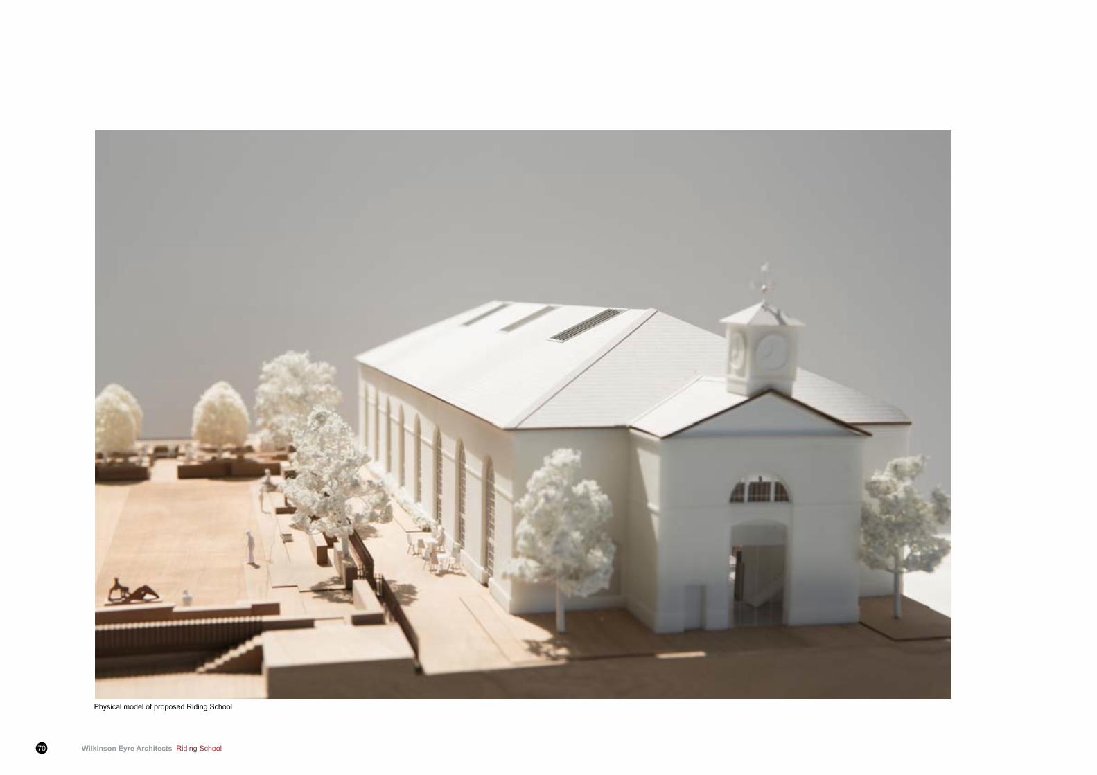
Wilkinson Eyre Architects Riding School70
Physical model of proposed Riding School

Riding School Wilkinson Eyre Architects 71
9.1 Statutory and regulatory background 9.1.1 The Access Statement section of this Design and Access
Statement was prepared by access consultant Earnscliffe, Making AccessWork.ItsatisfiesPartMoftheBuildingRegulations2010,paragraphs 0.20 to 0.25, and CABE guidelines on the content and format requirements for Design and Access Statements.
9.1.2 This statement seeks to demonstrate how the design proposals takefullaccountoftheMayorofLondon’sLondonPlan,specificallySupplementary Planning Guidance “Accessible London: Achieving an Inclusive Environment” April 2004. It also demonstrates how the proposals meet the following national legislation and local planning and development policy requirements:
9.1.3 The Disability Discrimination Act 1995 (DDA) duties of the Equality Act 2010. The developers have ongoing obligations under the DDA as landlords and obligations as service providers.
• British Standard 8300:2009 - Design of Buildings and their Approaches to Meet the Needs of Disabled People.
• Approved Document M of the Building Regulations 2010, Access to and use of buildings.
• Westminster (WCC) SPG: STRA 26 – Improving access to facilities and buildings to ensure that all users have access to individual buildings and developments. Particular regard will be paid to the needs of people with disabilities.
9 Access Statement
Physical model of proposed Riding School_

Wilkinson Eyre Architects Riding School72
9 Access Statement
9.2 Design philosophy 9.2.1 The Access Strategy is based on the social model of disability
and the philosophy of inclusive design which maximises access, choice and opportunities for disabled people. Inclusive design is the process by which the needs of everybody are considered and embedded in the proposals for the design, development and subsequent management of the built environment from the outset. Thekeyelementsofinclusivedesign,whichbenefiteveryone,are:
a ease of use;
b freedom of choice and access to mainstream activities;
c embracing of diversity and difference;
d legibility and predictability; and
e high quality.
9.2.2 Access has been considered in its broadest sense to reflectthe needs of individuals with sensory, mobility and hidden impairments, learning disabilities, mental health needs, reduced or hypersensitivity to temperature, and limited reach and stature. Others to whom the built environment can be disabling, including young families, elders and people who have little understanding of written English, are also considered. This approach should facilitate an inclusive approach to access and ensure that opportunities for maximizingaccesstoallareasof thedevelopmentare identifiedthroughout the design process.
9.3 Riding School Spa and Pool9.3.1 The listed Riding School can be accessed from three points – one
ateachendof thebuildingatgroundfloor,oneat lowergroundfloorforprivateresidents.Theprincipalarrivalpointforresidentsarrivingatgroundfloor level isontheeasternendof theRidingSchoolwhilst the lowergroundfloor levelapproachwillbemostcommonly used by residents accessing the facility from their own residence. The public entrance is located at the western end of the Riding School.
Ground Floor
9.3.2 The Main Entrance comprises two sets of wide double sliding doors, separated by a generous lobby, with a doorman located off to one side. The entrance opens onto a generously proportioned Residents Lobby that contains lounge seating. A Part M compliant door located to one side of the Residents’ Lobby opens onto the SanctuaryGarden.Thedoorofferssufficientclearopeningwidthtoensure DDA compliance. Located beyond the Residents’ Lobby is a central core containing toilets. The toilet block contains a unisex wheelchair accessible WC whilst the three adjacent WCs are to ambulant disabled standard, with integral sinks.
9.3.3 The main circulation stair gives access to the Health Club/Changing facilitiesatlowergroundfloorlevel.Alternativeliftaccessisprovidedon both sides of the main stair. A Wet Lift is located on the other side of the toilet block, to be used by those accessing the pool at groundfloorlevelfromthechangingrooms.ADryLiftlocatedonthe opposite side of the core also provides access to the lower groundfloorlevel,closetotheHealthClub,andalsotheMezzaninelevel where it opens out into Club Lounge.
9.3.4 Two additional stairs run alongside the outer walls of the central core,oneconnectingtoMezzaninelevel,onetolowergroundfloor.All stairs are designed to ambulant disabled standard whilst the lifts exceed Part M standard.
9.3.5 The glazed partition walls separating the pool and central core will bear manifestations at two heights for the safety of visually impaired people.
9.3.6 The public entrance at the opposite end of the building, under a canopy, opens onto a large entrance lobby through wide sliding doors. This lobby contains ample seating and a reception point and leads through to the changing area which includes a wheelchair accessible combined shower/WC/ change room of 2.8m x 2m,
and additional single sex toilets and communal changing rooms (residents and public). There is level access from the changing rooms area to the poolside via a wide opening of 1500mm.
9.3.7 The pool has a generous clear perimeter area of approximately 3m, narrowing to an acceptable 1700mm alongside the pool stair. The pool has ladder access and additional access points in four corners to accommodate a hoist for disabled users. The pool-side showers have open access and so are widely accessible to all.
Lower Ground Floor
9.3.8 Residents can access the Riding School from their accommodation via the main circulation cores and drop off point.
9.3.9 A level access route leads through to the Health Club via a sizeable entrance lobby. Two easy access sliding doors are provided at the Health Club and a further sliding glazed screen opens into a 2.6m wide circulation corridor.
9.3.10 To the right of the circulation corridor are spacious segregated changing rooms and other health club facilities. Spacious wheelchair accessible male and female combined shower/WC/ change rooms are provided, each approximately 3m x 2m and both of which are conveniently located close to a lift and adjacent to the changing rooms.
Mezzanine Floor
9.3.11 There is liftandstairaccessfromgroundfloortothe largeClubLounge at this level. Whilst the small meeting room also on this level has stepped access only, there are meeting rooms provided atlowergroundfloorforinstanceswherepeopleareunabletousestairs. This represents an acceptable alternative access solution. These will be provided with hearing enhancement equipment.
9.3.12 The glazed screens outside the lounge area will bear manifestations at two heights to ensure the safety of visually impaired building users.
Riding School Wilkinson Eyre Architects 73
Fire Safety Strategy
9.3.13 Escape from the Riding School will be via either of the entrances. From Lower Ground Floor level there is escape on the level and by liftthroughtheSpaEntranceandthenceviatwofireexitspointsfrom the vertical circulation core close to the Drop Off point.
9.3.14 Considerationwillbegiventoprovisionofxenonbeaconvisualfirealarms in lift lobbies and toilets to augment the audible/PA system, for the safety of deaf people using the facility.
Conclusion
9.3.15 The Riding School has carefully considered access measures to ensure that private residents and public users can access the facility safely and with ease and convenience.

Wilkinson Eyre Architects Riding School74

Riding School Wilkinson Eyre Architects 75
10.0 Introduction10.0.1 The enabling works phase of the Proposed Development to the
Riding School (SJWS) will comprise the proposed demolition / removal works to surrounding buildings to the Riding School, as per Wilkinson Eyre Architects drawings 987-5000, 987-5001, 987-5002, 987-5003. These works include the demolition of the following:
• 1960’s extension on the west of the Riding School
• Simple lean-to and stand-alone canopy structures to the east of the Riding School
10.0.2 The following proposed works to the (Grade II Listed) Riding School building will, due to their nature and relevance to building stability, waterproofingetc,willlikelybecarriedoutduringtheconstructionphase and include:
• Demolish, removal and replacement of roof skylights;
• Demolish, removal of brick walls under south perimeter windows, to agreed levels;
• Demolish, removal and replacement of timber staircase and mezzaninetimberfloor;and
• Demolish, removal and formation of doorway on north-east corner of building wall.
10 Enabling works proposals
10.1 Scope of Works 10.0.1 The demolition contractor is responsible for producing and issuing
all proposals, sequences and programmes, risk assessments and methods statements (RAMS), and other associated documentation.
10.0.2 Prior to any demolition or enabling works taking place the following will be carried out:
• Condition / dilapidation survey of all retained adjacent structures, access roads and entranceways;
• Review type 2 asbestos survey reports and carry out full type 3 asbestos survey of all structures;
• Removal of any asbestos containing materials to approved RAMS,andcarryoutassociatednotificationprocedures;and
• Anyliveserviceswillbeidentifiedandeitherisolated,divertedor removed.
10.0.3 The scope will include the following:
• Demolition contractor preparing RAMS and associated documentation which satisfy CDM and H&S policies. This will include an independent structural assessment of any adjoining structure to prove that it in no way provides stability to the retained / remaining structure.
• Soft strip (internal) and removal of external furniture and fixings.
• Demolition of structural elements as described above (Paragraph 10.0.1) in a safe manner, generally following (but not limited to) a top-down sequence.
• Crushallsuitablearisingsonsiteto6F2specificationandleave on site in stockpiles.
• Removal of all other demolition arisings off site; site to be left levels and tidy.
• Records of waste duty of care documents will be maintained and remain available for inspection.
10.0.4 All staff appointed to carry out the works shall be suitably trained and qualified, and be required towear the necessaryPPE.Allplant and equipment shall be in goodworking order and fit forpurpose. All works on site shall be carried out in accordance with the appropriate statutory regulations and guidance notes.

The St. John’s Wood Square Project The Riding School: Design & Access Statement
Applicant: St. John’s Wood Square Ltd