the stream engine® · little routine maintenance, your stream engine will provide you with years...
TRANSCRIPT

The Stream Engine® Easy Tune® Generator
Owner’s Manual
Please Read Carefully
Made in North America
By
PO Box 4557 Sussex NB
Canada E4E 5L7
Phone +1 (506) 433-3151 Fax +1 (506) 433-6151
Email: [email protected] Website: www.microhydropower.com
The Stream Engine and Easy Tune are a Trademark of Energy Systems & Design Ltd.
V1.1 3-2012

Congratulations on your purchase of a new Easy Tune Stream Engine! With a proper installation and a little routine maintenance, your Stream Engine will provide you with years of trouble-free operation. This manual will help you to install your machine as well as assist you in trouble-shooting and problem solving. Of course, you may contact Energy Systems & Design Ltd. if you run into trouble. May your RE adventures prove successful! Table of Contents
Introduction .............................................................................................. 3 Site Evaluation ......................................................................................... 3 Head Measurement .................................................................................. 3 Flow Measurement................................................................................... 4 Stream Engine Output in Watts Table ..................................................... 5 Intake, Pipeline & Tailrace ...................................................................... 6-7 Batteries, Inverters & Controllers ............................................................ 7-8 Wiring and Load Center........................................................................... 8-9 Design Example ....................................................................................... 9-10 Output Adjustment ................................................................................... 11 High Voltage ........................................................................................... 12 Determining Nozzle Size ......................................................................... 12 Nozzle flow chart...................................................................................... 13 Disassembly and Bearing Replacement .................................................. 13-15 Copper Wire Resistance Chart ................................................................ 15 Pipe Friction Head Loss Charts .............................................................. 16-17 Wiring ...................................................................................................... 17-19 Installation Examples……………………………………………………20-21

3 INTRODUCTION The Stream Engine uses a tunable permanent magnet type alternator called the Easy Tune ®. This design eliminates the need for brushes and the maintenance that accompany them while increasing efficiency. The Easy Tune’s output can be optimized by simply moving the upper part of the generator. This manual describes The Easy Tune Stream Engine, which is manufactured by Energy Systems and Design Ltd. The installer must have some knowledge of plumbing and electrical systems, as should the end user of the system. These machines are small, but can generate very high voltages. Even 12-volt machines can produce high voltages under certain conditions. Practice all due safety. Electricity cannot be seen and can be lethal. Electrical systems must be installed in accordance with local laws by a qualified person. It is important to consult with local officials before conducting any watercourse alteration. ES&D advises following all local laws and ordinances regarding watercourses. Electricity is produced from the potential energy in water moving from a high point to a lower one. This distance is called "head" and is measured in units of distance (feet, meters) or in units of pressure (pounds per square inch, kilo-Pascals). "Flow" is measured in units of volume (gallons per minute - gpm, or liters per second - l/s), and is the second portion of the power equation. The power available is related to the head and the flow. The Stream Engine is designed to operate over a wide range of heads and flows. This is achieved with the use of a Turgo runner, or wheel. Nozzle diameters of 1/8 to 1 inch (3-25mm) are available, and up to four nozzles can be used on one machine, to utilize heads as low as four feet and as high as hundreds. SITE EVALUATION Certain information must be determined concerning your site, in order to use its potential for maximum output. Head and flow must first be determined. Other factors are: pipeline length, transmission distance, and the system voltage. These factors determine how much power can be expected. Power is generated at a constant rate by the Stream Engine and stored in batteries as direct current (DC). Power is supplied, as needed, by the batteries, which store energy during periods of low consumption for use in periods where consumption exceeds the generation rate. Appliances can be used that operate directly from batteries, or 120 volt alternating current (AC) power can be supplied through an inverter, converting DC to AC power. Sites may vary, so carefully consider flow and head when choosing yours. Remember, maximum head can be achieved by placing the Stream Engine at as low an elevation as possible, but going too low may cause the machine to become submerged (or washed away!). HEAD MEASUREMENT Head may be measured using various techniques. A garden hose or length of pipe can be submerged with one end upstream and the other end downstream. Anchor the upstream end with rocks or have an assistant hold it; water should flow out the low end, especially if the pipeline is pre-filled. Once water is flowing, raise the downstream end until it stops. Do this slowly since the water tends to oscillate. When the flow has stabilized, measure the distance down to the level of water in the stream with a tape measure. This will give a very accurate measurement of that stream section. Mark the spot and then repeat the procedure until the entire distance is covered.

4 Another technique is to use a surveyor's transit. This method can also be approximated using a carpenter's level along with a measuring stick or a "story pole." This technique is also done in a series of steps to arrive at the overall head. A variation on this method is the use of altimeters. GPS equipment could also be used to measure elevation. FLOW MEASUREMENT The easiest method to measure small flows is to channel the water into a pipe using a temporary dam and to fill a container of known volume. Measuring the time to fill the container enables you to calculate the flow rate.
WEIR MEASUREMENT TABLE
Table shows water flow in gallons/minute (gpm) that will flow over a weir one inch wide and from 1/8 to 10-7/8 inches deep.
Inches 1/8 1/4 3/8 1/2 5/8 3/4 7/8 0 0.0 0.1 0.4 0.7 1.0 1.4 1.9 2.4 1 3.0 3.5 4.1 4.8 5.5 6.1 6.9 7.6 2 8.5 9.2 10.1 10.9 11.8 12.7 13.6 14.6 3 15.5 16.5 17.5 18.6 19.5 20.6 21.7 22.8 4 23.9 25.1 26.2 27.4 28.5 29.7 31.0 32.2 5 33.4 34.7 36.0 37.3 38.5 39.9 41.2 42.6 6 43.9 45.3 46.8 48.2 49.5 51.0 52.4 53.9 7 55.4 56.8 58.3 59.9 61.4 63.0 64.6 66.0 8 67.7 69.3 70.8 72.5 74.1 75.8 77.4 79.1 9 80.8 82.4 84.2 85.9 87.6 89.3 91.0 92.8 10 94.5 96.3 98.1 99.9 101.7 103.6 105.4 107.3
Example of how to use weir table: Suppose depth of water above stake is 9 3/8 inches. Find 9 in the left-hand column and 3/8 in the
top column. The value where they intersect is 85.9 gpm. That's only for a 1-inch weir, however. You multiply this value by the width of your weir in inches to obtain water flow.

5 The weir method is more versatile and may prove useful for higher flows. This technique uses a rectangular opening cut in a board or piece of sheet metal set into the brook like a dam. The water is channeled into the weir and the depth is measured from the top of a stake that is level with the edge of the weir and several feet upstream. Looking at the chart that follows will enable you to convert the width and depth of flowing water into gallons per minute. Measuring the flow at different times of the year helps you estimate maximum and minimum usable flows. If the water source is seasonally limited, you may have to depend on some other source of power during dry times (solar, wind). Keep in mind that a reasonable amount of water must be left in the stream (Don't take it all, that water supports life forms). When head and flow are determined, the expected power output can be determined from the following chart. Keep in mind that chart values represent generated output and that actual power delivered to the batteries will be reduced by transmission lines, power converters, and other equipment required by the system. All systems should be carefully planned to maximize power output.
Stream Engine Output in Watts (Continuous)
* In these higher output situations, it may be worthwhile to utilize more than one Stream Engine.
Net Head Flow Rate Liters/sec (Gallons/min)
0.67 (10)
1.33 (20)
2.50 (40)
5.00 (75)
6.67 (100)
7.50 (112)
9.50 (150) Meters Feet
3 10 - 20 40 75 100 130 150 6 20 15 40 80 150 200 250 350 15 49 45 100 200 375 500 650 800 30 98 80 200 400 750 1000 * * 60 197 150 400 800 1500 * * * 90 295 200 550 1200 * * * * 120 394 300 700 1500 * * * * 150 492 400 850 1900 * * * *

6
INTAKE, PIPELINE, AND TAILRACE Most hydro systems require a pipeline. Even systems operating directly from a dam require at least a short plumbing run. It is important to use the correct type and size of pipe to minimize restrictions in the flow to the nozzle(s). When possible, pipelines should be buried; this stabilizes the line and prevents animals from chewing it. At the inlet of the pipe, a filter should be installed. A screened box can be used with the pipe entering one side, or add a section of pipe drilled full of holes wrapped with screen or small holes and used without screen. Make sure that the filter openings are smaller than the smallest nozzle used. Note that particles over about ¼” or 6mm in size may lodge in the runner. The intake must be above the streambed so as not to suck in silt and should be deep enough so as not to suck in air. The intake structure should be placed to one side of the main flow of the stream so that the force of the flowing water and its debris bypasses it. Routinely clean the intake of any leaves or other debris. If the whole pipeline doesn't run continuously downhill, at least the first section should, so the water can begin flowing. A bypass valve may be necessary. This should be installed at a low point in the pipe. For pipelines running over dams, or in conditions that create a siphon, the downstream side may be filled by hand. Once filled, the stop valve at the turbine can be opened to start the flow. If full pressure is not developed, or air builds up in the line, a hand-powered vacuum pump can be used to remove air trapped at the high point. At the turbine end of the pipeline a bypass valve may be necessary to allow water to run through the pipe without affecting the turbine, purging the line of air or increasing flow to prevent freezing. A stop valve should be installed upstream of the nozzle. A pressure gauge should be installed upstream of the stop valve so both the static head (no water flowing) and the dynamic head (water flowing) can be read. The stop valve on a pipeline should always be closed slowly to prevent water hammer (the column of water in the pipe coming to an abrupt stop). This can easily destroy your pipeline and for this reason, you may wish to install a pressure relief valve just upstream of the stop valve. This can also occur if debris clogs the nozzle. In a single nozzle machine a nozzle that becomes clogged suddenly may create a water hammer. Nozzles can be installed or changed by removing the nozzle. The nozzle is removed by unscrewing its four nuts using a 7/16” (11 mm) wrench. The use of flexible pipe makes it easier to remove the plumbing from the nozzles.

7
The turbine housing can be mounted on two boards to suspend it above the stream. It is recommended to have the Stream Engine in a small enclosure or under some cover to keep it dry and provide a place for auxiliary equipment. Mounting the machine in concrete is also possible (you may wish to try a temporary wood mounting first). The opening under the housing to catch the water should be at least the size of the turbine housing opening, and preferably a little larger. Make certain the tailrace (exit channel) provides enough flow for the exiting water. The diameter of the bolt holes is ¼” (6mm). In cold climates, it may be necessary to build a "trap" into the exit. This prevents outside air from entering the housing and causing freeze-ups. BATTERIES, INVERTERS & CONTROLLERS System Voltage A small system with a short transmission distance can be designed to operate at 12 volts. Larger systems can also be 12 volts, but if higher power is desired or the transmission distance is long, then a system of 24 volts or higher may be preferable. This is especially true if all loads are inverter-powered. In a 12-volt system operating at a low power level, it may be advantageous to operate all loads directly from batteries. Many 12-volt appliances and small inverters are available. In 24-volt systems, it may also be preferable to operate the loads directly (although not as many appliances are available).
OUTSIDE DIMENSION
9 1/2” Square Base Opening 24cm
11” 28cm
BOLT HOLES – ¼” dia 6mm
11” 28cm
12” 30.5cm

8 In higher power systems, it is usually better to use an inverter to convert battery voltage to regular 120 volt AC power at 60Hz (cycles per second), or 240 volt 50Hz in some countries. This has been made feasible with the advent of reliable high power inverters. Thousands of home power systems are in operation with only AC loads. Sizing Battery Bank A typical hydro system should have about one or two days of battery storage capacity. This will generally keep lead-acid cells operating in the middle of their charge range where they are the most efficient and long-lived. Batteries should be located outside of any living space, or adequate ventilation should be provided, as a rising charge level tends to produce both hydrogen gas and corrosive fumes. Also, distilled water should be added as needed to maintain the electrolyte level. Charge Control Unlike solar systems, a hydro system must always be connected to a load even when the batteries are fully charged. If the output power does not have a load, system voltage can rise to very high levels. This situation provides an opportunity to do something with the excess power like water or space heating. As the batteries become fully charged, their voltage rises. At some point, the charging process should stop and the excess power be diverted to the dump load. Most charge controllers permit different charge levels such as bulk, absorption, and float. Literature supplied with the controller should be consulted to determine the set points of the charge controller. Be sure to set the controller for hydro diversion. Watt-Hour meters are available that monitor the battery state of charge. An ammeter that monitors turbine output should always be installed in a high traffic or living space so difficulties with the machine can be easily detected. If a drop in output is noticed, the machine should be inspected. This could be caused by air in the pipeline, or a blocked or partially blocked nozzle. More importantly, a drop in output could be the beginning of bearing failure. Bearing failure will cause serious damage to the machine. Early detection of problems with the bearings is vital.
WIRING AND LOAD CENTER Every system requires wiring to connect the various components. Load centers are available as a complete package that easily facilitates the connection of loads and power source(s). All circuits in the system should use wire of adequate size and have fuses or breakers of sufficient capacity to carry the expected load current. The Stream Engine must be fused since it can suffer from a short or similar fault just like anything else in the system.

9 DESIGN EXAMPLE This example shows how to proceed with a complete installation. The parameters of the example site are:
-120 feet of head over a distance of 1000 feet -a flow of 30 gpm (most of the time) -100 feet of distance from the house to the hydro machine -24 volt system
The first thing we do is determine the pipeline size. Although maximum power is produced from a given size pipe when the flow loss is 1/3 of the static head, more power can be obtained from the same flow with a larger pipe, which has lower losses. Therefore, pipe size must be optimized based on economics. The pipe flow charts show us that two-inch diameter polyethylene pipe has a head loss of 1.77 feet of head per 100 feet of pipe at a flow rate of 30 gpm. This is 17.7 feet of loss for 1000 feet of pipe. Using two-inch PVC gives us a loss of 1.17 feet of head per 100 feet of pipe or 11.7 feet for 1000 feet. Polyethylene comes in continuous coils because it is flexible (and more freeze resistant). PVC comes in shorter lengths and has to be glued together or purchased with gaskets (for larger sizes). Let's say we select polyethylene. The maximum output occurs with a flow of about 45 gpm since that gives us a head loss of 3.75 feet per 100 feet of pipe, or 37.5 feet of loss for our 1000 feet of pipe. This is 37.5' loss/120' head = 31% loss. A flow of 30 gpm gives a net head of 102.3 feet (120' - 17.7'). The losses caused by the various pipe fittings and intake screen will further decrease the dynamic head, so 100 feet is a good working figure for the net head. Looking at the nozzle flow chart, we see that a 3/8” nozzle will produce a flow of 27.6 gpm at a head of 100’. This is very close to the design point and the net head will be a bit higher since the flow is less. Looking at the output chart we see that the machine could generate about 300 watts. That is, at a 30 meter head or about 100 feet and halfway between 20 and 40 gpm. A simple rule of thumb to use is to multiply the head in feet (meters) by the flow in gpm (liters per second) and divide by ten (multiply by five for metric or SI units) which will roughly give the output in watts. Since we require 24 volts and the transmission distance is fairly short, we can generate and transmit 24 volts using the Stream Engine. This Stream Engine could also be used for higher voltages like 48 and 120 or 240. With higher voltages, the power could be transmitted longer distances. We need to go 100' with 300 watts at our site. This will be about 10 amps at 30 volts at the generator. Note that there will be some voltage drop in the line and 24-volt batteries require somewhat higher voltages than nominal to become charged. So the 10 amps must pass through 200' of wire for the round trip. Resistance losses should be kept as low as economics permit, just like the pipeline losses.

10 Let's say we can accept around a 10% loss. This is 30 watts out of the original 300. The formula for resistive loss is I2R = watts. I = Intensity (current in amps) and R = Resistance (in ohms).
(10 amps)² x R (ohms) = 30 watts 100 amps x R (ohms) = 30 watts R = 30 watts/100 amps R = 0.3 ohms
This is the wire resistance that will produce a 10% loss. The wire loss chart shows loss per 1000', so:
1000'/200' x 0.3 ohms = 1.5 ohms per 1000'. The chart shows 12 ga. Wire has a resistance of 1.62 ohms per 1000', so:
200'/1000' x 1.62 ohms = 0.32ohms. This is close to the desired level. 10 amps x 10 amps x 0.32 ohms = 32 watts of loss.
Increasing the wire size further would reduce the losses. Voltage drop in the wire is equal to:
IR = 10 amps x 0.32 ohms = 3.2 volts
So if the battery voltage is 26.8 the generator will be operating at 30.0 volts. Keep in mind that it is always the batteries that determine the system voltage. That is, all voltages in the system rise and fall according to the battery's state of charge. At the site, we would be generating 10 amps continuously. If we use lead acid batteries and wish to have two days of storage capacity, then:
10 amps x 24 hrs x 2 days = 480 amp. hours (Ah) Capacity We would probably use an inverter and load controller with the system. The diagram for such a system would look like this:
Diagram of a typical battery-based system:

11
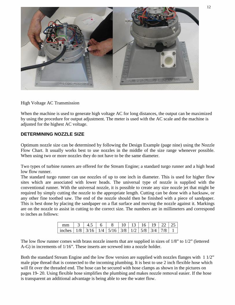
OUTPUT ADJUSTMENT The Easy Tune Stream Engine has the unique feature of being adjustable for maximum power while it is running! When the machine is fully installed and running, it can be easily adjusted for maximum power. This is done by measuring the output current or amps while the machine is generating power. Simply use your digital multi-meter to determine the highest output reading and set the machine at that point. In a battery system, the current is measured by connecting the meter that is supplied with the machine to the red and black jack as shown in the photo. The weather cover is lifted off after backing off the wingnuts that retain it. With the meter set for 200 DC millivolts (nine o’ clock position) it will read directly in amps. The DC output voltage can be read by setting the meter on the DC volts position (20, 200 volts) and using the black and white jacks as shown in the photo.
Once the meter is connected and the machine is operating, the upper body of the machine is rotated slightly using the two big knobs on the sides of the machine. First these are loosened and then the body of the machine can be moved while you are observing the output as shown in the photo. What you are looking for is the highest number on the meter. When this is found, the knobs can be tightened and no further adjustment is necessary unless there is a nozzle change. Note that there are two small screws that limit the movement of this adjustment that correspond to maximum and minimum magnetic engagement.
12
High Voltage AC Transmission When the machine is used to generate high voltage AC for long distances, the output can be maximized by using the procedure for output adjustment. The meter is used with the AC scale and the machine is adjusted for the highest AC voltage.
DETERMINING NOZZLE SIZE Optimum nozzle size can be determined by following the Design Example (page nine) using the Nozzle Flow Chart. It usually works best to use nozzles in the middle of the size range whenever possible. When using two or more nozzles they do not have to be the same diameter. Two types of turbine runners are offered for the Stream Engine; a standard turgo runner and a high head low flow runner. The standard turgo runner can use nozzles of up to one inch in diameter. This is used for higher flow sites which are associated with lower heads. The universal type of nozzle is supplied with the conventional runner. With the universal nozzle, it is possible to create any size nozzle jet that might be required by simply cutting the nozzle to the appropriate length. Cutting can be done with a hacksaw, or any other fine toothed saw. The end of the nozzle should then be finished with a piece of sandpaper. This is best done by placing the sandpaper on a flat surface and moving the nozzle against it. Markings are on the nozzle to assist in cutting to the correct size. The numbers are in millimeters and correspond to inches as follows:
mm 3 4.5 6 8 10 13 16 19 22 25 inches 1/8 3/16 1/4 5/16 3/8 1/2 5/8 3/4 7/8 1
The low flow runner comes with brass nozzle inserts that are supplied in sizes of 1/8” to 1/2” (lettered A-G) in increments of 1/16”. These inserts are screwed into a nozzle holder. Both the standard Stream Engine and the low flow version are supplied with nozzles flanges with 1 1/2” male pipe thread that is connected to the incoming plumbing. It is best to use 2 inch flexible hose which will fit over the threaded end. The hose can be secured with hose clamps as shown in the pictures on pages 19- 20. Using flexible hose simplifies the plumbing and makes nozzle removal easier. If the hose is transparent an additional advantage is being able to see the water flow.

13
NOZZLE FLOW CHART FLOW RATE IN U.S. GALLONS PER MINUTE
Note: This chart is for one nozzle. More than one nozzle can be used to accommodate greater flow. If head and flow conditions are at machine capacity increasing nozzle size will only produce slightly more power. The Stream Engine can generate a maximum of about 750 watts per 1000 rpm. DISASSEMBLY and BEARING REPLACEMENT In order to replace bearings, the turbine runner must first be removed. Take the small steel rod (1/4”) that is supplied with the machine and insert it into one of the holes in the side of the machine casting. First rotate the runner so the shaft will turn and then find the hole in the rotor and insert the pin. This will keep the shaft from rotating. Once the shaft is stable you will need to remove the runner wheel. If your machine has a turgo runner, unscrew it as you would a large nut by turning it in a counterclockwise direction while looking at the runner. If it is the type with the low flow runner, then remove the center bolt by turning it counterclockwise. Now the generator can be removed from the machine by removing the four nuts (7/16” 11mm) that are on the underside of the housing.
Head Feet
Pressure PSI
Nozzle Diameter, inches Turbine RPM
1/8 3/16 1/4 5/16 3/8 7/16 1/2 5/8 3/4 7/8 1.0 5 2.2 6.18 8.40 11.0 17.1 24.7 33.6 43.9 460 10 4.3 3.88 6.05 8.75 11.6 15.6 24.2 35.0 47.6 62.1 650 15 6.5 2.68 4.76 7.40 10.7 14.6 19.0 29.7 42.8 58.2 76.0 800 20 8.7 1.37 3.09 5.49 8.56 12.4 16.8 22.0 34.3 49.4 67.3 87.8 925 30 13.0 1.68 3.78 6.72 10.5 15.1 20.6 26.9 42.0 60.5 82.4 107 1140 40 17.3 1.94 4.37 7.76 12.1 17.5 23.8 31.1 48.5 69.9 95.1 124 1310 50 21.7 2.17 4.88 8.68 13.6 19.5 26.6 34.7 54.3 78.1 106 139 1470 60 26.0 2.38 5.35 9.51 14.8 21.4 29.1 38.0 59.4 85.6 117 152 1600 80 34.6 2.75 6.18 11.0 17.1 24.7 33.6 43.9 68.6 98.8 135 176 1850 100 43.3 3.07 6.91 12.3 19.2 27.6 37.6 49.1 76.7 111 150 196 2070 120 52.0 3.36 7.56 13.4 21.0 30.3 41.2 53.8 84.1 121 165 215 2270 150 65.0 3.76 8.95 15.0 23.5 33.8 46.0 60.1 93.9 135 184 241 2540 200 86.6 4.34 9.77 17.4 27.1 39.1 53.2 69.4 109 156 213 278 2930 250 108 4.86 10.9 19.9 30.3 43.6 59.4 77.6 121 175 238 311 3270 300 130 5.32 12.0 21.3 33.2 47.8 65.1 85.1 133 191 261 340 3591 400 173 6.14 13.8 24.5 38.3 55.2 75.2 98.2 154 221 301 393 4140
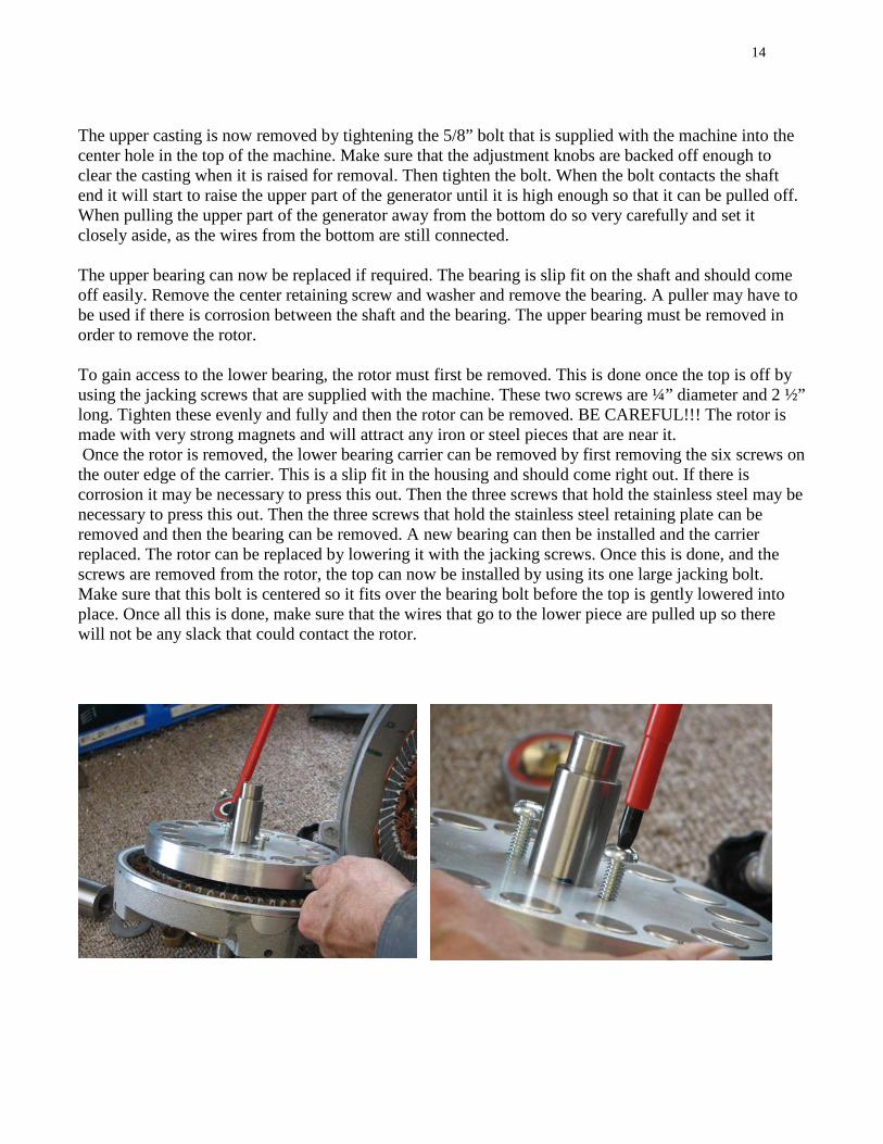
14 The upper casting is now removed by tightening the 5/8” bolt that is supplied with the machine into the center hole in the top of the machine. Make sure that the adjustment knobs are backed off enough to clear the casting when it is raised for removal. Then tighten the bolt. When the bolt contacts the shaft end it will start to raise the upper part of the generator until it is high enough so that it can be pulled off. When pulling the upper part of the generator away from the bottom do so very carefully and set it closely aside, as the wires from the bottom are still connected. The upper bearing can now be replaced if required. The bearing is slip fit on the shaft and should come off easily. Remove the center retaining screw and washer and remove the bearing. A puller may have to be used if there is corrosion between the shaft and the bearing. The upper bearing must be removed in order to remove the rotor. To gain access to the lower bearing, the rotor must first be removed. This is done once the top is off by using the jacking screws that are supplied with the machine. These two screws are ¼” diameter and 2 ½” long. Tighten these evenly and fully and then the rotor can be removed. BE CAREFUL!!! The rotor is made with very strong magnets and will attract any iron or steel pieces that are near it. Once the rotor is removed, the lower bearing carrier can be removed by first removing the six screws on the outer edge of the carrier. This is a slip fit in the housing and should come right out. If there is corrosion it may be necessary to press this out. Then the three screws that hold the stainless steel may be necessary to press this out. Then the three screws that hold the stainless steel retaining plate can be removed and then the bearing can be removed. A new bearing can then be installed and the carrier replaced. The rotor can be replaced by lowering it with the jacking screws. Once this is done, and the screws are removed from the rotor, the top can now be installed by using its one large jacking bolt. Make sure that this bolt is centered so it fits over the bearing bolt before the top is gently lowered into place. Once all this is done, make sure that the wires that go to the lower piece are pulled up so there will not be any slack that could contact the rotor.
15
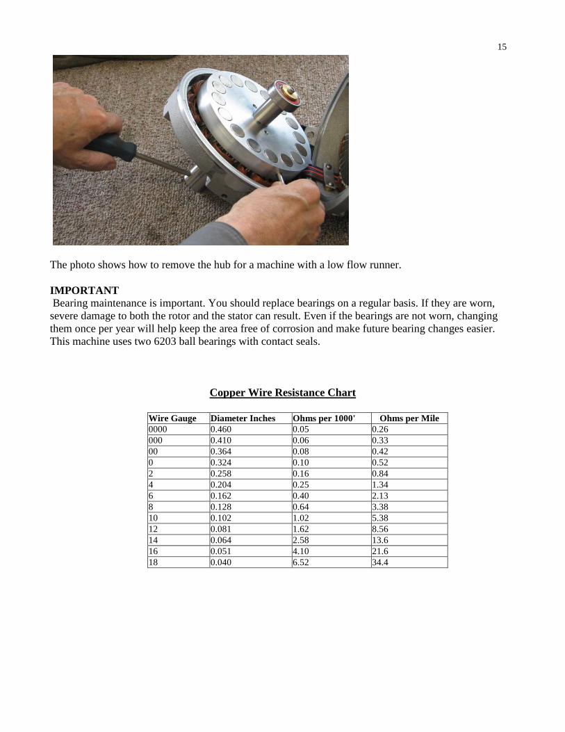
The photo shows how to remove the hub for a machine with a low flow runner. IMPORTANT Bearing maintenance is important. You should replace bearings on a regular basis. If they are worn, severe damage to both the rotor and the stator can result. Even if the bearings are not worn, changing them once per year will help keep the area free of corrosion and make future bearing changes easier. This machine uses two 6203 ball bearings with contact seals.
Copper Wire Resistance Chart
Wire Gauge Diameter Inches Ohms per 1000' Ohms per Mile 0000 0.460 0.05 0.26 000 0.410 0.06 0.33 00 0.364 0.08 0.42 0 0.324 0.10 0.52 2 0.258 0.16 0.84 4 0.204 0.25 1.34 6 0.162 0.40 2.13 8 0.128 0.64 3.38 10 0.102 1.02 5.38 12 0.081 1.62 8.56 14 0.064 2.58 13.6 16 0.051 4.10 21.6 18 0.040 6.52 34.4

16
PIPE FRICTION LOSS - PVC Class 160 PSI Plastic Pipe Pressure Loss from Friction in Feet of Head per 100 Feet of Pipe
Flow US GPM Pipe Diameter, Inches 1 1.25 1.5 2 2.5 3 4 5 6 8 10
1 0.05 0.02 2 0.14 0.05 0.02 3 0.32 0.09 0.04 4 0.53 0.16 0.09 0.02 5 0.80 0.25 0.12 0.04 6 1.13 0.35 0.18 0.07 0.02 7 1.52 0.46 0.23 0.08 0.02 8 1.93 0.58 0.30 0.10 0.04 9 2.42 0.71 0.37 0.12 0.05 10 2.92 0.87 0.46 0.16 0.07 0.02 11 3.50 1.04 0.53 0.18 0.07 0.02 12 4.09 1.22 0.64 0.20 0.09 0.02 14 5.45 1.63 0.85 0.28 0.12 0.04 16 7.00 2.09 1.08 0.37 0.14 0.04 18 8.69 2.60 1.33 0.46 0.18 0.07 20 10.6 3.15 1.63 0.55 0.21 0.09 0.02 22 12.6 3.77 1.96 0.67 0.25 0.10 0.02 24 14.8 4.42 2.32 0.78 0.30 0.12 0.04 26 17.2 5.13 2.65 0.90 0.35 0.14 0.05 28 19.7 5.89 3.04 1.04 0.41 0.16 0.05 30 22.4 6.70 3.45 1.17 0.43 0.18 0.05 35 8.90 4.64 1.56 0.62 0.23 0.07 40 11.4 5.89 1.98 0.78 0.30 0.09 0.02 45 14.2 7.34 2.48 0.97 0.37 0.12 0.04 50 17.2 8.92 3.01 1.20 0.46 0.14 0.04 55 20.5 10.6 3.59 1.43 0.55 0.16 0.05 60 24.1 12.5 4.21 1.66 0.64 0.18 0.07 0.02 70 16.6 5.61 2.21 0.85 0.25 0.09 0.03 80 21.3 7.18 2.83 1.08 0.32 0.12 0.04 90 8.92 3.52 1.36 0.39 0.14 0.07
100 10.9 4.28 1.66 0.48 0.18 0.07 0.02 150 23.2 9.06 3.50 1.04 0.37 0.16 0.05 200 15.5 5.96 1.75 0.62 0.28 0.07 0.02 250 23.4 9.05 2.65 0.94 0.42 0.12 0.05 300 12.6 3.73 1.34 0.58 0.16 0.05 350 16.8 4.95 1.78 0.76 0.21 0.07 400 21.5 6.33 2.25 0.97 0.28 0.10 450 7.87 2.81 1.20 0.32 0.12 500 9.55 3.41 1.45 0.42 0.14 550 11.4 4.07 1.75 0.48 0.16 600 13.4 4.78 2.05 0.58 0.18 650 15.5 5.54 2.37 0.67 0.23 700 17.8 6.37 2.71 0.76 0.25 750 20.3 7.22 3.10 0.86 0.30 800 8.14 3.50 0.97 0.32 850 9.11 3.89 1.08 0.37 900 10.1 4.32 1.20 0.42 950 10.8 4.79 1.34 0.46
1000 12.3 5.27 1.45 0.51

17 PIPE FRICTION LOSS Polyethylene SDR - Pressure Rated Pipe
Pressure Loss from Friction in Feet of Head per 100 Feet of Pipe
Flow US GPM Pipe Diameter, Inches 0.5 0.75 1 1.25 1.5 2 2.5 3 1 1.13 0.28 0.09 0.02 2 4.05 1.04 0.32 0.09 0.04 3 8.60 2.19 0.67 0.19 0.09 0.02 4 14.6 3.73 1.15 0.30 0.14 0.05 5 22.1 5.61 1.75 0.46 0.21 0.07 6 31.0 7.89 2.44 0.65 0.30 0.09 0.05 7 41.2 10.5 3.24 0.85 0.42 0.12 0.06 8 53.1 13.4 4.14 1.08 0.51 0.16 0.07 9 16.7 5.15 1.36 0.65 0.18 0.08
10 20.3 6.28 1.66 0.78 0.23 0.09 0.02 12 28.5 8.79 2.32 1.11 0.32 0.14 0.05 14 37.9 11.7 3.10 1.45 0.44 0.18 0.07 16 15.0 3.93 1.87 0.55 0.23 0.08 18 18.6 4.90 2.32 0.69 0.30 0.09 20 22.6 5.96 2.81 0.83 0.35 0.12 22 27.0 7.11 3.36 1.00 0.42 0.14 24 31.7 8.35 3.96 1.17 0.49 0.16 26 36.8 9.68 4.58 1.36 0.58 0.21 28 11.1 5.25 1.56 0.67 0.23 30 12.6 5.96 1.77 0.74 0.25 35 16.8 7.94 2.35 1.00 0.35 40 21.5 10.2 3.02 1.27 0.44 45 26.8 12.7 3.75 1.59 0.55 50 32.5 15.4 4.55 1.91 0.67 55 18.3 5.43 1.96 0.81 60 21.5 6.40 2.70 0.94 65 23.8 7.41 3.13 1.08 70 28.7 8.49 3.59 1.24 75 32.6 9.67 4.07 1.40 80 10.9 4.58 1.59 85 12.2 5.13 1.77 90 13.5 5.71 1.98 95 15.0 6.31 2.19
100 16.5 6.92 2.42 150 34.5 14.7 5.11 200 25.0 8.70
WIRING SCHEMES 12 VOLTS 24 VOLTS 48 VOLTS
Parallel Y max current 30A 0-25’/8m
Series Y max current 10A 5’/ 1.5m to 15’/5m
Series Y max current 10A 10’/3m to 30’/ 9m
Parallel Delta max current 50A 20’/6m and up
Series Delta max current 17A 10’/3m to 25’/8m
Series Delta max current 17A 25’/8m to 100’/30m
Parallel Y max current 30A 20’/6m to 100’/30m
Parallel Y max current 30A 80’/24m to 250’/76m
Parallel Delta max current 50A 80’/ 24m and up
Parallel Delta max current 50A 200’/ 60m and up

18 A Stream Engine Easy Tune® Generator wired delta Moving the wires with the yellow ends for wye
To change wiring from delta to wye, move the wires (orange, brown, and blue) with the yellow ends on the rectifier to the empty stud on the transparent terminal block. Using the wye connection will raise the voltage and lower the current. Using the delta connection will increase the current and lower the output voltage. This is fine tuning compared to the internal wiring that is discussed later. The wires with the red ends go to the rectifier and the wires with the blue ends go to the terminal block. There is a ground lug marked with green, for grounding the machine. The negative output, marked with black, is on the terminal block and is isolated. The positive output, marked with red, is on the rectifier. There are three fuses, one for each phase. These fuses protect the internal wiring. If the current goes over the safe limit a fuse may open. If new fuses are needed always replace them with the exact type as supplied with the machine. INTERNAL WIRING Inside the machine is additional wiring that determines the output voltage and current of the machine. This can be connected in parallel to give lower voltage and higher current, and series is used to give higher voltage and lower current output. There are two terminal blocks where the wiring changes are made. One serves the upper half of the generator and the other serves the lower half. Both terminal blocks must have the same wiring. The top part of the generator is removed by inserting and tightening the bolt in the center of the machine as described previously. This gives access to the upper terminal block. The rotor is removed to gain access to the lower terminal block. The procedure is described in the bearing and disassembly section.

19 Parallel Wiring Look at the photographs of the wiring for the parallel connections and you will see that only two of the terminal screw connections are used for each section or phase. The terminal blocks are divided into three sections which are separated by the mounting screws that have a flat hex head. Only the two screws at either side are used in the parallel scheme. These screws are also connected to the output wiring so you will see a wire with a ring terminal exiting the terminal block and passing under the magnet wire of the stator. The colored stator wires must be connected to these lead wires too. Note that the extra screws that are needed to series connect the machine are in place if going to series wiring is ever required. So all of the colored stator leads are connected to only two points for each of the three sections. As shown in the photograph, white, blue and yellow wires are connected to one terminal screw and the black, red and green wires are connected to the other screw. This is repeated as shown around the terminal block until all of the connections are the same. Parallel Series Series Wiring For series wiring the machine, look at the photograph that shows this. You will see that for this scheme, you will connect wires to all four of the screw terminals in each of the three sections. These screws are separated by the three flat head screws that are used to mount the terminal blocks. The first and last screws are also connected to the lead wires so these must also be connected when changing the wiring. The first screw will have only the white wires connected to them, along with the lead wire end. The next screw will have both the black and blue wires connected. The next screw will have the red and yellow wires connected. The last screw will have the green wire and the lead wire connected. This is done at all three of the sections to complete the wiring.
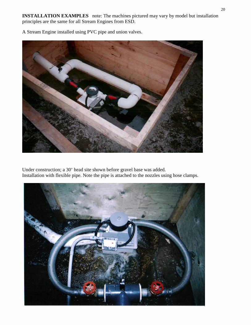
20 INSTALLATION EXAMPLES note: The machines pictured may vary by model but installation principles are the same for all Stream Engines from ESD. A Stream Engine installed using PVC pipe and union valves.
Under construction; a 30’ head site shown before gravel base was added. Installation with flexible pipe. Note the pipe is attached to the nozzles using hose clamps.
21 Note pressure gauge installed by drilling and tapping the T fitting and using a small valve. This allows removal of the gauge to prevent freezing damage to the gauge.
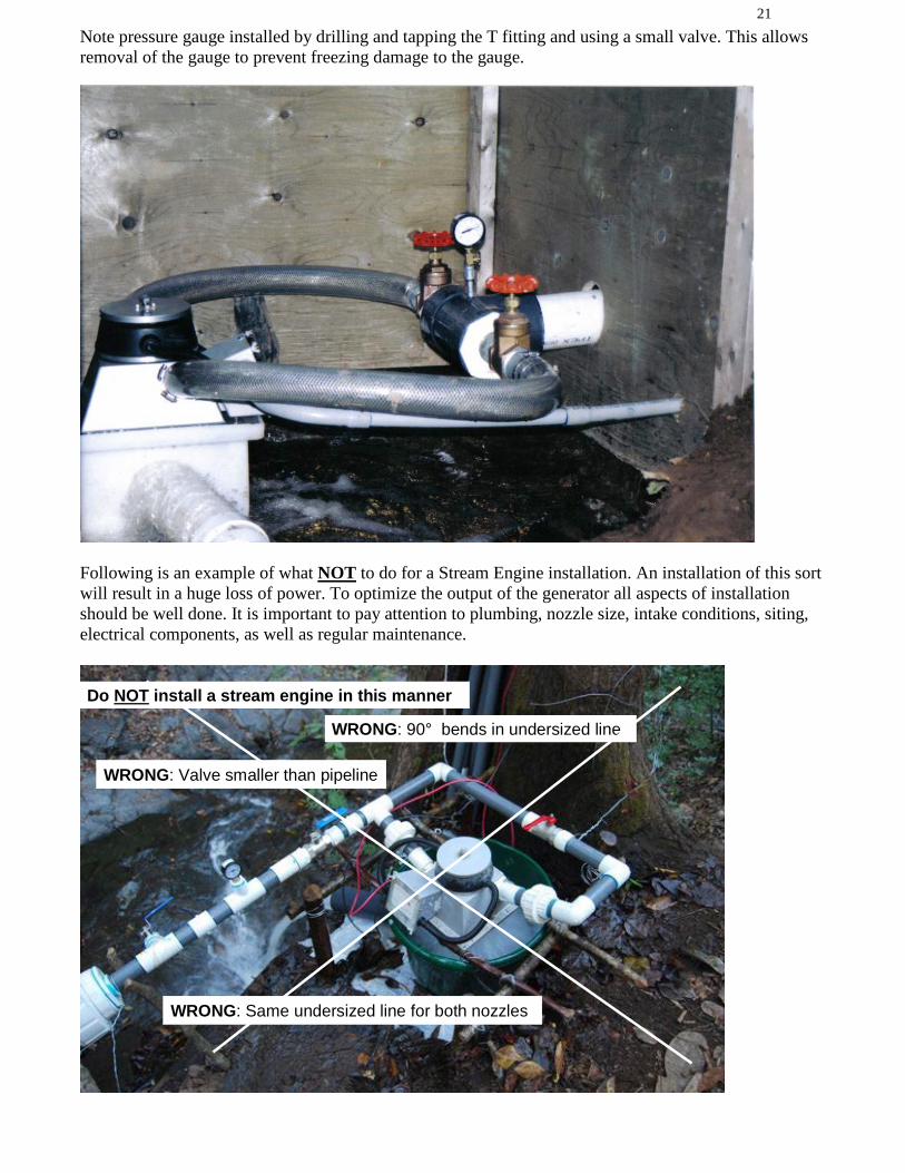
Following is an example of what NOT to do for a Stream Engine installation. An installation of this sort will result in a huge loss of power. To optimize the output of the generator all aspects of installation should be well done. It is important to pay attention to plumbing, nozzle size, intake conditions, siting, electrical components, as well as regular maintenance.
WRONG: 90° bends in undersized line
Do NOT install a stream engine in this manner
WRONG: Same undersized line for both nozzles
WRONG: Valve smaller than pipeline

GUARANTEE This machine is guaranteed to change your life. The fine print: This ES & D water powered generator is warranted against defects in workmanship and materials. The period that this covers is one year, starting at the date of shipment to the customer. In the event that an ES & D machine is found to have defects in material or workmanship, the remedies of repair or replacement of parts shall in each case be at the reasonable discretion of ES & D. Machines that the purchaser claims are defective must be returned at the purchaser’s cost. ES & D will not be responsible for problems caused by improper maintenance, faulty installation, unauthorized modifications or additions, abuse, or any other cause not due to defects in the machine. ES & D will not be held liable for consequential damages or interruption of service to the buyer. The buyer, furthermore, by acceptance of the equipment assumes all responsibility for the consequences of its use. After one year from the shipping date, all liability terminates and no action for any breach of any such warranty may be commenced.

Personal Hydropower
Product Information Model # _____________________ Serial # ____________________ Date Purchased __________________________________________ Purchased From __________________________________________ Name: __________________________________________________ Address: ________________________________________________ City: ___________________________________________________ State/Prov: _________________ Zip/Postal Code: ______________ Telephone: ______________________________________________ Email: __________________________________________________ Comments: ______________________________________________ ________________________________________________________
__________________________________________
Made in Canada
By
Energy Systems and Design Ltd. PO Box 4557 Sussex NB
Canada E4E 5L7
Phone +1 (506) 433-3151 Fax +1 (506) 433-6151
Email: [email protected] Website: www.microhydropower.com