the university of north texas - facilities | facilities · 9/1/2017 · the university president....
TRANSCRIPT

i
DESIGN & CONSTRUCTION GUIDELINES The University of North Texas Rev. 3 September 1, 2017

ii
DESIGN & CONSTRUCTION GUIDELINES
TABLE OF CONTENTS
Page Introduction 2
A. Planning Procedures 3 1.0 Designer’s Relationship to the University 3 2.0 Initial Planning Conference 3 3.0 Site and Existing Conditions Information 3 3.1 Survey Criteria 3 3.2 Geotechnical Engineer 4 4.0 Project Development Schedule 4 5.0 Review of Design 4 5.1 Conference Memoranda 4 5.2 Submittals for Outside Review 4 5.3 Submittals for University Review 5 5.4 Payments to Designer 5 6.0 Project Development Phases 5 6.1 Schematic Design Phase 5 6.2 Design Development Phase 6 6.3 Construction Documents Phase 6 6.4 Bidding Phase 7 7.0 Construction Phase 7 7.1 Pre-Construction Conference 7 7.2 Periodic Observations 7 7.3 Submittal Review 8 7.4 Project Close-out Responsibilities 8
B. Design Guidelines 9 1.0 General Considerations 9 1.1 Campus Design 9 1.2 Drawings and Specifications Formats 9 1.3 Design Within Available Funds 9 1.4 Building Codes & Project Standards 9 1.5 Energy and Materials Conservation 10 1.6 Flexibility 10 1.7 Maintainability 11 1.8 Accessibility 11 1.9 Exterior Windows 11 1.10 Standard Stock Items 11 1.11 Recruitment and Selection of Minority Businesses 11 1.12 Dangerous Chemicals. Liquids, and Gases 11 1.13 Radiation Sources 11 1.14 Special Scheduling and Construction Constraints 11 1.15 Usage of Color 11

iii
2.0 Site Design 11 2.1 Project Site 11 2.2 Site Limits 12 2.3 Walks, Ramps, steps, and Building Entry 12 2.4 Parking 12 2.5 Paving 12 2.6 Outdoor Spaces 12 2.7 Site Drainage 12 2.8 Erosion and Sediment Control 13 2.9 Landscaping 13 2.10 Exterior Lighting 34 2.11 Outdoor Recycling and Solid Waste Collection Site 35 2.12 Site Accessories 36 2.13 Exterior Signage 37 2.14 Site Utilities 37 2.15 Shielding of Equipment 38 2.16 Protection of Underground Tanks and Pipes 38 2.17 Emergency Phones 38 3.0 Building Envelope 38 3.1 Exterior Materials 38 3.2 Glazing 40 3.3 Doorways 40 3.4 Exterior Storefronts 40 3.5 Roof Access 40 3.6 Ledges and Bird Roosts 40 4.0 Superstructures 40 4.1 Special Foundations 40 5.0 Interior Layout and Construction 40 5.1 General 40 5.2 Space Organization 42 5.3 Office Standards 42 5.4 Classrooms 42 5.5 Custodial Closets 43 5.6 Hazardous Materials Room 43 5.7 Mail Service Facilities 43 5.8 Mechanical and Electrical Equipment Rooms 43 5.9 Recycling Alcoves 43 5.10 Telecommunications 43 5.11 Building Address 48 5.12 Room Numbering 48 5.13 Temporary Egress 48 5.14 Laboratory Buildings 48 5.15 Asbestos in Buildings 48 5.16 Interior Signage 48 5.17 Millwork 48

iv
6.0 Finishes and Equipment 49 6.1 Selection and Procurement 49 6.2 Floor Materials 49 6.3 Interior Wall Finishes 50 6.4 Safety Color Coding 50 6.5 Window Covering 50 6.6 Elevators 50 6.7 Elevator Controller 51 6.8 Elevator Equipment Rooms 51 6.9 Door Hardware 51 7.0 Furniture and Equipment 52 7.1 Furniture Selection and Procurement 52
7.2 Furniture Lighting 52
7.3 Furniture Coordination 52
7.4 Furniture Installation 52
7.5 Power Clusters at Private Offices 53
7.6 Modesty Panels on Modular Furniture 53
7.7
7.8
Fixed Equipment
Moveable Equipment 53
8.0 Building Service Systems 53
8.1 General 53 8.2 Energy Conservation 53 8.3 HVAC System 54 8.4 Air Handling System 55 8.5 Water Cooling Systems 58 8.6 Central Utility Distribution System 59 8.7 Plumbing Systems 60 8.8 Fire Suppression System 62 8.9 Power Distribution System 62
8.10 Interior Lighting 67
8.11 Fire Alarm and Detection Systems 69
8.12 Rooftop Equipment 70
8.13 Lightning Protection 70
C. The Construction Contract 71
1.0 General 71 2.0 Shop Drawings, Submittals, Samples, Data 71 2.1 Selection of Brick or Cast Panels for Exterior Walls 71 3.0 Materials, Equipment, Employees 71 3.1 Specification of Competitive Materials 71 3.2 Condition of Contiguous Work 71 4.0 Permits, Inspection, Fees, Regulations 71

v
4.1 Permits and Fees 71 5.0 Protection of Work, Property, and the Public 71 5.1 Protection of Underground Utilities Lines 71 5.2 Protection of Storm Drainage System 72 5.3 Protection of Existing Landscape 72 5.4 Protection of Campus Buildings, Streets, and Sidewalks 72 5.5 Shutdown of Existing Fire Protection Systems 73 5.6 Generating Smoke, Heat, or Dust 73 5.7 Safety Measures 73 5.8 Security Measures 73 5.9 Hazard Communication Measures 73 5.10 Asbestos Containing Materials 73 6.0 Inspection and Testing 73 7.0 Use of Premises 74 7.1 Use of Owner’s Drinking and Toilet Facilities 74 7.2 Contractor’s Working Hours 74 7.3 Noise-Making Activities 74 7.4 Temporary Interruption of Utilities and Traffic Movement 74 7.5 Site Limits 74 7.6 Contractor Parking and Storage 74 8.0 Utilities, Structures, and Signs 75 8.1 Utilities 75 8.2 Signs and Construction Sites 75 8.3 Identification by Room Number 75 9.0 Cleaning Up 75 10.0 HUB Subcontracting Plan 75
D. Selection and Evaluation Policy 77 1.0 Architect Selection Process 77 1.1 General 77 1.2 Evaluation 77 2.0 Contractor Selection Process 77 2.1 General 77 2.2 Evaluation 77
Appendix A Peripheral Campuses Standards 78 Appendix B Telecommunications 81 Appendix C Fire Alarm Specifications 82
Appendix D Distributed Learning Videoconference Room Design Consideration 89
Appendix E
Guide For The Standardization Of The Campus Automation System
94
Appendix F Interior Signage Standards 96

vi
Appendix G
Appendix H
Illustrations, Diagrams, and Standard Details
Facilities Planning, Design and Construction CAD Standards
105
151
Appendix I Transformer Specification 160
Appendix J
UNT Facilities Attic Stock Procedures 164

2
INTRODUCTION
This handbook, Design and Construction Guidelines, is prepared to assist Architects and Engineers in
the design and construction of physical facilities for The University of North Texas. The information collected in this
manual is based upon past experience with design practices, maintenance issues, construction methods, equipment
and materials which have provided the quality of construction the University requires.
These guidelines are designed to supplement the policies and the procedures of the Texas State Building
Commission, the latest edition of the UNT System Uniform General Conditions and the Supplementary General
Conditions for Construction and Design Contracts. It is assumed that all professionals providing design services for
the University are familiar with these policies and procedures.
It is recognized that particular project situations shall, in the judgment of the Designer, warrant deviations
from these standards. We welcome any such recommendations and shall consider each of them carefully. However,
unless the University gives specific approval for alternatives prior to implementation, the Designer must comply with
the guidelines in this publication.
We also welcome recommendations for additions or improvements of this document from users. Please
submit any comments or suggestions to the Director of Facilities Planning, Design & Construction.
The information in this manual is organized to follow the sequence of the design process. The first section
outlines the Planning Procedures which are followed for every University capital project, and it is organized by the
phases of the planning process: Schematic Design, Design Development, Construction Documents, Bidding,
Construction, and Project Close-out.
The second section contains Design Guidelines that represent the University's expectations regarding the
design of the specific elements and systems typically involved in University projects.
The third section, The Construction Contract, outlines specific requirements pertaining to the nature of the
construction contract and to the conduct of construction work at the University.
The fourth section, Selection and Evaluation Policy, contains information about the procurement of
Architectural and Construction Services. The University of North Texas has established these policies in order to
provide fair and equitable evaluation of the firms that are soliciting these opportunities.
The fifth section collects Standard Details that are referenced throughout the manual.


3
A. PLANNING PROCEDURES
1.0 Designer's Relationship to the University The Designer should understand that all UNT Campus Buildings are under the authority of the University President. UNT Facilities is responsible for the operations and maintenance of all non-Auxiliary buildings and therefore should be considered the “owner” – even though project planning and design for the University is a cooperative procedure involving many persons within the UNT System, Campus, State Agencies and other reviewing authorities. At any point in time there is a single representative assigned to each project. This is the person through whom the Designer is required to work and to whom the Designer should turn for authoritative information on all matters and questions involving the University. Many other individuals and groups within the University will participate in the capital improvement planning process, but the Designer should not act on any information other than that received from, or coordinated through, the designated project representative – herein referred to as the Project Manager. The Project Manager is the contact for all information during the initial phases of a project--the programming phase, the designer selection, the design, and the bidding phases. This individual coordinates and monitors all project activities for the University. The Designer shall designate an individual within his or her firm who is directly responsible for the project, and who can be contacted on any matter pertaining to the project. 2.0 Initial Planning Conference An initial planning conference will be scheduled to discuss general requirements of the program and procedures for facilitating the Designer's work. This conference is held as soon as possible after selection of a Designer for the project. The Designer's professional consultants for plumbing, HVAC, and electrical design should attend this conference as necessary. 3.0 Site & Existing Conditions Information The University shall furnish topographic surveys and other existing information for new construction; including record drawings for remodeling projects. The University cannot warrant that this information is correct. The Designer shall supplement this information with his or her own field surveys and measurements. The Designer is responsible for reporting to the owner any inaccuracy in the information shown on the construction contract drawings. 3.1 Survey Criteria Surveyors contracted by the University shall comply with the following guidelines:
A. Digital Data Requirements • Provide AutoCAD format electronic file with each feature, e.g., sidewalks, roads, buildings, fences, trees, etc, on
separate layers. • Surveys must be referenced to one of the three UNT GIS benchmarks. UNT Campus Facilities will provide the
metadata as needed. • Coordinate system must be State Plane 4202 TXNC Zone, with units of feet. Elevations must be based on GEOID03
NAVD88 as the datum. Latitude and Longitude should be based on NAD 83 (CORS96) (EPOCH:2002.0) as the datum.
• Data attribute formats must be in Excel, DBF4, or tab/comma delimited text files. • Pertinent metadata must be provided.
B. Length of each property line C. Measure angle at each property corner D. Iron pin set at each corner E. Indicate any corner radius F. Location of any existing buildings, driveways, sidewalks, etc. G. Location of any fences or structures within 50’ outside of property line H. Indicate any easements, right of ways, and building set back lines I. Establish permanent benchmark location and note on survey J. Width of street K. Type of pavement for each street L. Height and type of curb and show existing curb cuts M. Width and type of sidewalks N. Location and size of gas, water, and other know underground utilities including storm and sanitary sewer lines with flow
lines and top of manholes O. Location of existing gas and water meters P. Show catch basins with size and elevation of grating and flow line

4
Q. Location of fire hydrants, traffic signs, street light, power and telephone poles, guy wires, etc. R. Location of trees and type and size S. Show depth and size of basements T. Give elevations in 1’ intervals. Show any unusual grade changes U. If a drainage ditch is along any side of the property line, give elevations of bottom and crest of ditch V. Coordinate with Facilities Maintenance for locations and tie-ins of underground utilities
3.2 Geotechnical Engineer (if employed by Designer) In addition to providing the normal sub-surface investigation written report, the Geotechnical Engineer is thoroughly involved in the design process and shall complete the following tasks prior to submittal of Construction Documents.
A. Review and edit the project’s earthwork specifications, final site and structural foundation drawings for compliance with the soils report recommendations.
B. Estimate the quantities of weathered and bedrock excavation for bid purposes. C. Any special analysis or report as required by special circumstances, situations or projects.
4.0 Project Development Schedule The Designer shall prepare and submit a proposed Project Development Schedule to the Project Manager for approval. This schedule is submitted within twenty-one (21) calendar days of the date of the Design Contract, and it shall incorporate the end-of-phase milestone dates stipulated in the Design Contract. In addition, this schedule shall show:
A. The start dates and duration of each major phase of design. B. The duration and completion dates of each design review period, which are required to maintain the project schedule. For
most projects, the normal design review periods are: Schematic Design Review (ten calendar days), Design Development Review (two weeks), Construction Documents Review (thirty calendar days) and Final Review and Approval (two weeks).
C. The projected duration and completion dates of other project-related activities, such as funding decisions, surveys, sub-surface investigations and zoning approvals.
D. The estimated duration of the construction contract award process and the construction period. The Project Development Schedule is up-dated and re-submitted with each end-of-phase submittal described below. 5.0 Review of Design The Designer is required to make submittals and presentations, and to participate in review conferences at various stages of the project planning process.
A. Presentations and Review Conferences During the design process, the Designer is expected to make presentations to various groups who must review and approve the proposed project designs. These groups include the user group, various groups of UNT System and Campus Facilities, other officials of the University, and the Board of Regents of the University. The Project Manager schedules all conferences and presentations.
B. Schematic Design Conferences Normally several conferences precede the approval of Schematic Design documents. Conferences are required to clarify the program of requirements, to review and discuss the Designer's design proposals, to discuss the Designer's evaluation as to whether the program requirements are achievable within the project budget and to assist in the definition of alternates which shall become an important component of the Construction Documents.
C. Presentation to Board of Regents The Designer may be asked to make a presentation of the project design to the Facilities Committee of the Board of Regents for their comments and approval. The following exhibits are typically required for these presentations: A simple scale model showing the siting and vicinity of the project (except for renovation projects), the building floor plans, the exterior elevations and possibly a sketch or rendering. These presentations are scheduled to occur as early as possible in the Design Development Phase of project.
D. End-of-Phase Reviews At least one conference is devoted to the end-of-phase reviews of the Design Development submittal and Construction Documents submittal for the purpose of discussing any areas of concern that arise during the review process. The Designer and the Designer's primary consultants are expected to attend these review conferences.
5.1 Conference Memoranda
The Designer is expected to record the content of all conferences and, within seven (7) days, provide a memorandum containing a complete summary of the decisions and actions that will affect the project. This memorandum is distributed to all conferees.
5.2 Submittals for Outside Review
Local building permits are not required. The designer shall submit plans to all appropriate agencies for review and approval, except as noted below. The owner shall submit plans and documentation to the Texas Higher Education Coordinating Board for review and approval. The Designer is required to provide the background and technical materials necessary to support

5
these submittals; including a storm water management plan, erosion control plan, and/or traffic control plan. The Designer shall attend public hearing(s) related to these submittals, as required.
5.3 Submittals for University Review
In addition to the various State and Local agencies that may exercise plan review authority over the project, various departments within the University also participate in plan reviews at stages specified in the Designer’s contract. The University's Project Manager shall coordinate these reviews. The review team consists of the following UNT departments. Though individual titles may change, the current review team is as follows:
System Facilities Associate Vice Chancellor Project Manager/Architect Director of System Planning and Development Construction Manager
Campus Facilities Vice President for Facilities Grounds Maintenance Manager Dir. Facilities Planning, Design & Construction Door Systems Director of Facilities Maintenance Project Coordinator (for furniture and finishes) Structural Maintenance Manager
Custodial Services Manager
Maintenance Manager Utilities Manager Fire Systems Supervisor
Police, Parking & Transportation Dir/Chief, Police & Traffic
Communications & Information Technology Communications Managers (Telecom & Datacom) Dir Communications Services Computer Systems Mgr
Risk Management & Environmental Services Dir Risk Mgmt/Environmental Services Asst Dir Risk Mgmt & Environmental Services Life Safety
Classroom Support Services Dir. Micro Computer Maintenance/ Classroom Support
Office of Disability Accommodation Disabilities Accommodations Dir.
Departmental Dean (if it is an academic project) & Primary Departmental Contact
The University review team will submit comments as necessary. Upon receipt of the review comments, the Designer shall revise the Design Documents in accordance with the review comments. The Designer shall prepare a written summary of his or her response to the University's review, and the Designer shall provide a copy of this to the Project Manager within two weeks of the Designer's receipt of the review comments. The Designer shall not proceed to the next phase before receiving written approval of the previous phase from the University's Project Manager.
5.4 Payments to Designer
The Designer shall submit invoices to the Project Manager for approval. Invoice formats shall comply with the following format. The Designer may submit invoices on a monthly basis for up to 90% completion of design phase. The remaining 10% is invoiced upon written approval of design submission.
6.0 Project Development Phases 6.1 Schematic Design Phase
At the beginning of the Schematic Design Phase, the Designer shall confer with the Project Manager and the users to review the program and establish the project requirements. Based on an approved summary of the project requirements, the Designer shall prepare a Schematic Design illustrating the recommended implementation of the program and project requirements. The Designer is expected to involve the assigned Project Manager – and through that individual, the user group and other appropriate members of the University's Facilities – during the development of the schematic design. The Designer is expected to explore a range of alternatives that best implement the program and project requirements.

6
Schematic Design Submittal The Schematic Design Submittal to the University shall be per contract or as discussed prior to submittal. Include the following information as a minimum:
A. Show proposed walkways, vehicular and service access on the site plan. Include existing landscape. B. Identification of each room or space by functional name on floor plans. C. An updated Project Design Schedule.
6.2 Design Development Phase
Based upon the approved schematic submittal, the Designer shall prepare the Design Development documents.
Design Development Submittal The Design Development Submittal to the University shall be per contract or as discussed prior to submittal. Include the following information as a minimum:
A. Site drawing(s) showing adjacent buildings, significant existing features including existing landscaping, site utilities, proposed construction limits, proposed site improvements, and other site data furnished on the previous submittal.
B. Floor plans shall identify each room or space by name and number. All room numbers must reflect the permanent room numbering signage system. The University will establish the room numbering system prior to committing to the drawings (See Section B, 5.11)
C. Elevation drawings of every exterior side of each structure showing materials, features, openings, floor and rooflines, grade lines, footings, and everything exposed to view above eaves or parapets. Show partial elevations of adjacent campus buildings on elevation drawings.
D. Section(s) through the entire building selected to best show the relationships of architectural and engineering features.
E. A room finish schedule showing the type of material to be used for floors, walls, and ceilings. The proposed interior finishes concept shall be presented to the University for approval. The University must approve all finish materials selections prior to their specification by the Designer. This shall include concepts for the following:
• All floor material types and locations. • All wall finish materials and locations. • Identify exterior materials, including wood species, brick and/or stone. • Identify millwork locations and materials • Identify ceiling materials and locations.
F. Equipment and furniture layouts for all rooms indicating the adequacy of the arrangement and configuration of such rooms for planning telephone and data requirements.
G. An outline specification indicating materials, types of construction, and equipment to be used. Include a description of each plumbing, HVAC, fire protection and electrical system design concept. Include elevator characteristics, and include the names of proposed manufacturers of HVAC, plumbing, fire protection, special systems, electrical equipment and fixed equipment.
H. The maximum hot water and chilled water demand--for the purpose of determining whether the existing heating and cooling systems will be adequate to meet anticipated demand or whether modifications to these systems or a new stand alone system will be required.
I. A tabulation of building data, including square feet of floor area, cubic content, roof deck "U" factor, heating load in BTUH, air conditioning in tons, plumbing load in drainage fixture units, water demand in peak GPM, electrical loads in KVA, the design live loads and number of occupants.
J. An up-dated Project Design Schedule. 6.3 Construction Documents Phase
Based upon the approved Design Development Submittal and written notice to proceed, the Designer shall prepare the Construction Documents. As stated in the Designer’s contract, the building design must be in compliance with all applicable codes, laws, ordinances, and regulations.
A. Owner’s reviews of Working Drawings are required at stages per the Designer’s contract. See Section B, 5.3. B. At 50% and 100% Final Construction Documents, provide the Project Manager with electronic floor plans in
AutoCAD format that include electrical, data, and intended furniture layout. C. Final Construction Documents Submittal
The Final Construction Documents shall be prepared as per contract or as discussed prior to submittal on sheets specified
• The first sheet of drawings shall include the following information: a tabulation of building data, including square feet of floor area, cubic content, roof deck "U" factor, maximum heating load in BTUH, air conditioning in tons, plumbing load in drainage fixture units, water demand in peak GPM, electrical loads in KVA, the design live loads and applicable codes, laws, ordinances, regulations and number of occupants.
• Provide a "color board" (2 copies) accurately depicting the interior and/or exterior materials, colors and finishes used on the project as well as their location within the project. As previously stated, all material selections must be reviewed and approved by the University prior to submittal of a “color board.”
• An up-dated Project Design Schedule. D. Specifications – UNT has limited storage space so attic stock shall be limited to certain items only. All new
buildings are required to provide a storage room specifically for permanent storage of attic stock materials. Please reference Appendix J for attic stock requirements.

7
6.4 Bidding Phase The Designer, in consultation with the project manager, shall establish the date for receipt of bids. A period of four to six weeks is normally required between the publication of the advertisement for bids and the receipt of bids. Newspaper notice of bidding the project is not required by law, although the Owner may choose to do so. The University will advertise in the Electronic State Business daily as required by law. The Designer will place adequate copies of all bid documents in the Dallas - Fort Worth metropolitan area plan rooms. The following plan rooms are to be used:
DFW Minority Business Development Council 1000 Stemmons Tower South 2720 Stemmons Freeway Dallas, Texas 75207-2212 (214) 630-0747
CMD/AGC Plan Room 11102 Stemmons Freeway, Suite 101 Dallas, Texas 75229 (972) 484-2030
Dodge FW McGraw Hill Construction Information 1341 W. Mockingbird Lane Dallas, Texas 75247
In addition, the Designer will notify general contractors known to the Designer or the University to be capable of doing the project. Written invitations to bid will state the name and location of the project, the owner, the designer and the pre-bid and bid opening dates, times and location. See UNT/HSP Policy in Section C, 10.0 A pre-bid conference will be scheduled to occur after bid documents have been available long enough for bidders to review and develop questions, but far enough before bid opening that bidders can adjust to a formal addendum from the designer answering all questions raised at the pre-bid.
The Designer shall provide bid tabulation forms and conduct the bid opening. Designer will advise the University on the implication of any irregularities or unexpected results of the bidding.
7.0 Construction Phase
The Construction Phase begins with the University’s receipt of the fully executed copy of the construction contract(s), performance bond, payment bond and insurance certificate. Upon approval of insurance coverage by the University of North Texas Risk Manager, the University will send a Notice To Proceed to the Contractor.
7.1 Pre-Construction Conference
The Designer, in consultation with the Project Manager, shall arrange for a pre-construction conference. The purpose of this meeting is to review the requirements of the project and to provide a framework for the coordination of all construction activities. The Designer shall invite all contractors, the University's Construction Manager and all other interested parties to this conference. The Designer shall distribute copies of meeting minutes to the parties outlined above.
7.2 Periodic Observations
The Designer, where required by the design contract, shall provide liaison and necessary observation of the project to ensure compliance with plans and specifications. The University's Construction Manager will also observe work progress periodically and will provide comments to the Designer through the Project Manager.
7.3 Submittal Review
The University’s Construction Manager will be responsible for coordinating in-house reviews of submittals with the necessary individuals at the University. Facilities Maintenance shall have an opportunity to review submittals before final is approved. After University approval, the Designer shall provide the Construction Manager with a copy of the final approved submittal. The Construction Manager will also coordinate material samples or mock-ups requiring University approval, including, if necessary, appropriate mock-up location.
7.4 Project Close-out Responsibilities
The Designer shall provide the following project closeout services upon completion of the project: A. Assemble and forward closing papers. B. Computation and disposition of liquidated damages (if required). C. Issue Certificate of Substantial Completion & Compliance including punch list / completion list.

8
D. Provide Electronic CAD Format Record Drawings as stated in Contract. The drawings should accurately reflect the project as constructed including finish materials, colors and any other architectural and MEP changes that occurred during construction.
E. Provide Facilities a separate list of all major fixtures & finishes (i.e., lights, wall paints, flooring, laminates, etc.) installed as part of the project.
F. Complete construction documents including as-built drawings prepared and provided to University archivist.
G. Attic Stock – Please reference Appendix J for attic stock procedures.
End of Planning Procedures

9
B. DESIGN GUIDELINES 1.0 Designer's Relationship to the University 1.1 Campus Design
The underlying goal of the architectural design of any new construction is to enhance and unify the campus. New construction should relate to adjacent buildings in character, mass, dimension, scale, building materials and fenestration.
The Designer must consider the impact of new construction on the existing campus infrastructure. This includes careful consideration of the project’s utility, pedestrian, parking, vehicular access and open space requirements. The project development must be consistent with the vehicular/pedestrian open space and utility systems proposed in the long-range plan. The design must also consider the long term health and retention of mature tree specimens on campus. Do not design any utility lines to be installed under tree canopies. If any trenching absolutely must occur under ANY tree, then utilize AIR SPADE trenching technology, offered by Root Flare Services of Dallas to open the trench. For projects on peripheral campuses, such as UNT Discovery Park and UNT Fort Worth Health Science Center, refer to the Supplemental Design Standards in Appendix A.
1.2 Drawings and Specifications Formats
Drawings will be prepared on 30” x 42”, black line on white paper, or as specified in the Designer’s contract. All specifications shall be prepared in bound form. Drawings will follow the CAD Standards implemented by Facilities Planning, Design and Construction. See Appendix H for information.
1.3 Design Within Available Funds
The Total Project Budget of a Capital Improvement Project includes the project construction cost, the design fee, a construction contingency fee and a number of project reserves. The reserves respond to local requirements and requirements established by the University. Among the University reserves itemized in the project budget are Utilities, Testing, Air Balance, Construction Supervision, Telecommunications and Moveable Equipment. These reserves are excluded from the funding allotted to the designer for construction. Designers are directed and required to base their designs upon the budgeted funds available. The Designer shall continually monitor program requirements and cost estimates to assure that the project is designed within the available funds and does not deviate from the quality standards established herein. If at any time the Designer believes that satisfying the stated program requirements at the level of quality desired will exceed the budgeted funds available, then s/he must inform the University's Project Manager without delay.
1.4 Building Codes & Project Standards The following building codes must be followed for all UNT projects. The Board of Regents adopts the latest edition of the International Building Code for all new construction and major renovations and the current edition of the NFPA 101 Life Safety Code used in a secondary role as a guide to interpretation of the IBC (NOTE – latest edition of codes/standards at commencement of project schematic design apply unless otherwise noted below):
International Building Code (IBC) International Mechanical Code (IMC) International Plumbing Code (IPC) International Energy Conservation Code (IECC) International Existing Building Code (IEBC) International Fire Code (IFC) National Electric Code (2014) or other applicable electric code Texas State Energy Code Texas Accessibility Standards ADA (Americans with Disabilities Act) NFPA 101 Life Safety Code NFPA 70E Arc Flash Safety (2017) ASTM 17.1-2007 Elevator and Escalator
NOTE – Please list all applicable codes on cover sheet of construction documents. The following project standards apply to all projects managed by UNTS, UNT and Non-UNTS Builder/Developer on the UNT campus:

10
UNT Master Plan (Latest Edition) UNT Design & Construction Guidelines (Latest Edition) UNT Tree Preservation Policy (2009) UNT practice for LEED Silver minimum UNT Campus Parking & Transportation Master Plan UNT & UNT System Policies as applicable Applicable Building Codes as amended by variance by UNTS AHJ
Applicable City of Denton requirements related to easements, Row’s and connectivity to city infrastructure (water, sewer)
City Tap & Impact Fees
1.5 Energy and Materials Conservation
The University is dedicated to the principle of conserving materials and energy. The Designer should scrutinize proposed construction for means of reducing not only the initial cost of energy and non-renewable resources, but also long-range reduction of operating costs. In addition to basic conservation requirements, the Designer should primarily consider the long-term maintenance and operations needs of the facility and apply advanced design technologies in renewable energy sources, recycled materials content and non-conventional materials while not compromising the practical maintenance and operations requirements of the facility. Take into account the climate of the southwest region of the United States and make sure the design reflects that consideration. For instance, windows may be recessed for shading. In the Specification, the Designer should encourage the Contractor to salvage scrap material to the maximum extent practical, especially scrap metals and lumber. In the product specifications, encourage vendors to offer products having recycled content.
Texas Law now requires that all new construction or major renovation undertaken by state agencies and state-supported institutions of higher education comply with the Texas State Energy Conservation Design Standards. The State Energy Conservation Office (SECO) through administrative rule adopted these standards effective September 1, 2011. An overview of the statue and rule follows:
Statutory Reference: Texas Government Code, 447.004 Rule Cite: Texas Administrative Code Title 34, Part 1, Chapter 19, Subchapter C, Rule 19.31-19.34 Applicability: This applies to all new construction or major renovation projects undertaken by state agencies and state-supported Institutions of Higher Education. Major Renovation Project: A building renovation or improvements that affects the energy or water use of the facility. For instance, a lighting project that requires engineering drawings would require certification, replacing lamps would not. For the purposes of 34 TAC Chapter 19, Subchapter C, a major renovation project is a building renovation or improvement where the implementation cost is $2 million or more, based on the initial cost estimate. Standards:
a. For any new construction or major renovation project, except low-rise residential buildings, with a design assignment made on or after September 1, 2011, the energy conservation design standard of the American Society of Heating, Refrigerating and Air Conditioning Engineers (ASHRAE) / Illuminating Engineering Society of North America (IESNA), Energy Standard for Buildings, ASHRAE/IESNA Standard 90.1-2010.
b. For public low rise residential buildings, the energy conservation design standard of the International Energy Code Council as published in the International Energy Conservation Code for 2000.
c. Effective September 1, 2011, SECO adopts by reference the “Water Efficiency Standards for State Buildings and Institutions of Higher Education Facilities” prepared by the Office of the Comptroller, State Energy Conservation Office dated January 2011 as the water conservation design standards for new state buildings and major renovation projects.
Certification: Before beginning construction of a new state building or a major renovation project, including a new building or major renovation project of a state-supported institution of higher education, a state agency or an institution of higher education shall submit to the State Energy Conservation Office (SECO) a copy of the certification by the design architect or engineer that verifies to the agency or institution that the construction or renovation complies with the standards that are established under this chapter, including engineering documentation. . This certification form can be found on the SECO website: http://www.seco.cpa.state.tx.us/ Routine maintenance and operational change out of material and equipment, where no engineering or architectural design assignment is necessary, are exempt from the submission of the compliance certification. All materials used for construction must not contain asbestos. Contractors are required to provide MSDS sheets for all materials used on a job as part of the submittal deliverable.
1.6 Flexibility by design Flexibility in the arrangement and use of a building is a fundamental requirement, and the ability to accommodate growth and change is an important criterion in the design of the structural, mechanical, and electrical systems and the selection of

11
materials. The Designer is encouraged to locate stairs and elevators on the periphery of the building to allow large blocks of continuous space inside the building. Flexibility of future use favors the creation of large free span areas of monolithic surface, so long as the design can carry the load. Recommended building heights are limited to three stories. In no case shall a building exceed five stories. Where expansion at a later time is considered, lateral, rather than vertical expansion is recommended.
1.7 Maintainability
Designers are required to consider long-term durability and maintainability, when selecting and specifying equipment, materials, and finishes. Initial cost is not the over-riding consideration. Allow service personnel access to equipment without disruption to campus activities. Size equipment rooms to permit maintenance, repair and easy removal of equipment. Locate equipment so that service personnel can easily gain access. Provide permanent ladders and platforms as required. Designers should comply with OSHA regulations for employee access to equipment via industrial stairs, working platform, ladder, etc., as well as NFPA working clearances for all equipment electrical cabinets. Locate mechanical and electrical equipment rooms with access to the exterior; provide convenient service vehicle access. Do not combine service closet and equipment room functions. Provide direct access to each individual service closet and equipment room. Sub-grade mechanical equipment rooms in new buildings are not allowed. Basements are not allowed. Fan and oil units will not be placed on the roof. No exterior part of the building should have any surface that requires painting.
1.8 Accessibility
The University is committed to making all buildings and areas of the campus physically accessible to all students, faculty and staff. Therefore, Designers are required to accommodate the special requirements of all segments of the University population – including wheelchair users, those who use walking aids and the hearing and visually impaired – in their design. All new construction shall fully comply with the Americans with Disabilities Act (ADA) of 2010. To the greatest extent possible, renovation projects shall bring the project areas within the facility to full ADA compliance.
1.9 Exterior Windows
Windows are not desirable in auditoriums, but they are desirable in public areas and offices. In general, do not extend windows below 30 inches above the floor or more than seven feet above the floor in offices. The general orientation of the building should consider the east and west solar exposure in the arrangement of windows and glass to minimize direct sunlight.
1.10 Standard Stock Items
Designers are directed and required to base their designs upon standard stock items whenever possible. Where custom-built items are required, the designer shall clearly state this fact.
1.11 Dangerous Chemicals, Liquids and Gases
The floor plans and storage arrangement of chemicals, flammable liquids and gases are subject to review for compliance with all applicable codes, and for common sense.
1.12 Radiation Sources The floor plans and equipment arrangement of all radiation sources are submitted to the Radiation Safety Officer, UNT Risk Management Office, for their review and approval. The Radiation Safety Officer shall submit safety recommendations as required.
1.13 Special Scheduling and Construction Constraints
Projects on campus require special steps to avoid or minimize interference with on-going campus operations. See Section C – The Construction Contract.
1.14 Colors: Materials/Finishes
The University encourages the use of UNT thematic colors for interior finishes and UNT branding for graphics. Refer to UNT identity guide at https://identityguide.unt.edu . The Designer should refrain from using any finish and material colors that might resemble those that are representative of other universities in the region.
2.0 Site Design 2.1 Project Site
The Designer may be asked to participate in the siting of the project. The Designer shall visit the site and evaluate proposed possible locations for the project, coordinate existing utilities, right of ways, easements, and discuss issues related to siting with the Project Manager before beginning design work. The Designer may suggest arrangements differing from those shown in the program requirements if site conditions warrant.

12
2.2 Site Limits The Designer shall establish the limits of the construction site in coordination with the University. Indicate these limits on the design development drawings. If use of parking lots for staging is required by the project, show the location of site fences, staging area. Enclose the construction area with a six feet (6') high (minimum) chain link type fence with top rail. The Contractor is required to remove the construction fence completely, including all portions of footings below ground level, at completion of the project. Remove fence posts -- do not saw off flush with the soil line. Drawings shall also specify the area used for material storage during construction.
Dimensional Control As part of project site preparation, the Contractor will install in the ground geodetic benchmark caps set in concrete to be used as dimensional control, as opposed to iron rods, concrete x-cuts or other benchmark objects. The Contractor must use a cap with a minimum 2” diameter and a 1.75” stem. Material may be aluminum or brass. The cap must be stamped with “University of North Texas” on the outer ring, “Secondary Point” on the inner ring, a point mark in the center, and a benchmark number below the point. Contractor must contact Facilities GIS to obtain available benchmark numbers for the project. Once set, a licensed surveyor must occupy these points and provide the metadata to the Contractor for use in the project. The coordinate system must be State Plane 4202 TXNC Zone, with units of Survey Feet. Vertical datum must be GEOID03 NAVD88. Horizontal datum must be NAD 83 (CORS96) (EPOCH:2002.0). Both Surface and grid values of horizontal and vertical positions must be provided, including the scale factor for conversion between the two values.
2.3 Walks, Ramps, Steps and Building Entry
Walkways • Carefully plan new walkways that connect major destinations and offer pedestrians a safe, accessible and relatively
direct means of travel. Indicate these new walkways on the schematic design site plan. • Give special consideration to locations where pedestrian pathways cross vehicular routes. Avoid steps and other
features hazardous to the visually impaired. Crosswalks must conform to city of Denton standards. Replace any exposed aggregate sidewalks within project limits. In other situations, mark the pedestrian crossing with generally recognized "cross-walk" stripes on the asphalt-paving surface (see Appendix G, Figure 3).
• Maintain consistent walkway widths across the campus. Remove walkways not in use. • The standard walkway widths are:
Major pedestrian corridors 16 feet wide All other pedestrian sidewalks 8 feet wide
Ramps and Steps
• Ramps and steps shall meet accessibility requirements in all locations. Provide railings and guards at stairwells, steps, bridges, loading docks and ramps per accessibility requirements. Treads and landings are to have positive drainage away from the building. Provide runways and ramps in all buildings where bulk supplies are handled. Ramps should have a non-slip surface attached Appendix G Figure 4. Carborundum or similar abrasives are not permitted. (eg. broom finish)
Building Entry
• All public entrances should be on grade, no monumental stairs, and meet accessibility requirements. 2.4 Parking
Parking areas must be clearly defined and physically separated from roads. Preserve existing trees to the greatest extent possible. Visually separate large parking lots into smaller modules (see Appendix G, Figure 5). Major lots should be paved, striped, delineated with curbs and gutters and proper illumination for safe evening use is required (see Section B, 2.10) The Designer must provide parking for emergency and delivery vehicles, as well as University service vehicles. In the case of dormitories and similar buildings, provide for the significant loading and unloading parking demands associated with student move-in/move-out days. See Section B, Error! Reference source not found. for parking lot painting requirements.
2.5 Paving All paving repairs shall match existing materials. Exposed aggregate will not be used.
2.6 Outdoor Spaces
Careful design of spaces in between buildings will integrate these interstitial spaces into the network of campus open spaces. Within these spaces there is the opportunity to create gathering spaces - “outdoor rooms.” Take care to locate these outdoor rooms where their activity and use will not disrupt or distract nearby classrooms or similar established activities. In developing outdoor spaces, the designer should look to the existing campus for precedents of form and material as well as lighting, signage and landscaping.

13
2.7 Site Drainage Grade the site, including paved areas, loading dock, service yards, and landscaped areas, so that gravity runoff occurs at all points. Slope all areas away from the building at a minimum gradient of 1/4 inch per foot. Grade all terrain surrounding the building, including loading and parking areas, in such a manner as to prevent water flow into the building should storm drains serving the area become stopped up. Provide an underground storm sewer system to accommodate the roof drainage system. Tie drainage from new construction into existing underground storm drains – Day-lighting of building sump pump discharge is not acceptable. Design the storm drainage system for assumed minimum rainfall intensity of two inches per hour for a five-hour storm. In addition, use 2.0 cubic feet per second per acre as the minimum runoff value in the storm drainage design. The maximum permissible horizontal distance between a catch basin and other inlet shall not exceed 75 feet. This applies to grass areas, paved areas, elevated parking areas, etc.
2.8 Erosion and Sediment Control
The Designer’s Erosion and Sediment Control Plan for the project shall follow UNT’s storm water pollution prevention plan (SW3P) and should clearly delineate between which measures are temporary and which are permanent.
2.9 Landscaping Landscape Design:
Design is to be water saving in nature. All plants are to be native or indigenous to the area that can survive with minimal additional water (with exception of establishment year). Beds are to be curvilinear in nature and design – no square corners, radius corners please. Designs are to draw the eye to various points or flow from point to point and lead to entry/exits and offer exciting visual vistas as pedestrians walk through the campus. Designs are to be interesting and relaxing to the viewer and should complement the building and surrounding landscape. Designs are to include sitting areas – or areas of reflection, quiet or study. Designs are to cascade from the building in stair step fashion – tall, medium and short in order to make the building a part of the landscape and not rigidly separate. Soften all vertical corners whenever possible. Designs are to include seasonal native perennial color for interest. Avoid continual ‘line of sight/view’ obstructions. Occasional tall accent plants are acceptable. For examples see Appendix G, Figures 6 & 7.
LANDSCAPE PLANTING:
General Conditions
The requirements of the University of North Texas System Uniform General Conditions and Supplementary General Conditions, 2013 Amended shall apply to all work of this section with the same force and effect as though repeated in full herein.
Scope of Work Furnish all labor, materials, equipment, and services necessary to provide all landscape planting for trees, shrubs, and ground covers, complete in place as shown on the plans and specified herein.
Definitions AAN: American Association of Nurserymen. Final Acceptance of Installation: This acceptance will be granted upon completion of installation of all plant materials
according to the plans and as specified herein. Final Acceptance of Installation will not occur before the Final Inspection. Final Inspection: The last inspection immediately prior to Final Acceptance of Installation. Owner: University of North Texas System. Quality Assurance
Contractor's Qualification: Demonstrated experience on projects of similar characteristics and size. Referenced Standards: the following references form a part of these specifications to the extent to which they are referenced:
1. American Association of Nurserymen, Inc., American Standard for Nursery Stock, 2004 edition. 2. Plant names are to comply with the standards of Hortis Third, 1976, Cornell University.
Quality Control 1. Contractor shall be responsible for all plant material shown on the plans. If discrepancies exist
between the count of plant materials as shown on the plans and listed on the plant list or bid items, the actual count on the plans shall be considered correct. Submit documentation to the Owner within 15 days after the award of the contract that all plant material is available. Any and all substitutions due to unavailability must be requested in writing and submitted with plant documentation mentioned above. All plant materials shall be subject to inspection and approval by the Owner at the place of growth or upon delivery to the site for conformity to the plans and specifications. Such approval shall not impair the right of inspection and rejection during progress of the work.
2. Contractor shall submit specifications of any item being used on-site upon the request of the Owner. Substitutions
• Substitution request for any material must be made in writing to Owner within 15 days after the award of the bid.

14
• Substitutions must possess same characteristics as material for which are to be substituted. • Substitutions submitted on materials of greater value than specified materials shall be provided at no
additional cos to the Owner. Damage to Existing Site Amenities
Damage to existing irrigation and electrical lines to remain shall be repaired within 24 hours of damage occurrence. If not repaired within the specified time, the Owner has the right to make such repairs as necessary and all costs incurred shall be charged to the Contractor.
Samples and Tests
1. Owner reserves the right to take and analyze samples of materials for conformity to specifications at any time. Contractor shall furnish samples of materials for testing upon request of the Owner. Rejected materials shall be immediately removed from the site at Contractor's expense. Cost of testing of materials not meeting specifications shall be paid by the Contractor.
2. Provide representative quantities (1 gallon plastic bag or container each) of each type of aggregate, imported topsoil, expanded shale, organic compost, and hardwood mulch. Attach product name, address of manufacturer and/or supplier and appropriate literature to each sample. Samples shall be submitted within 15 calendar days after contract award.
3. Plant Material samples: submit documentation within 15 calendar days after award of contract that all plant materials have been located and are ready to be secured. Arrange specific review procedure of plant materials at time of submission. Submittals and review shall be organized as follows:
a. Preliminary Review: submit representative photograph for review of all plant materials in the required sizes and in available quantity within 25 calendar days after award of contract.
b. Submittal shall include two color photographic images of each plant type and size, include the name and address of the supplier, size of the plant in the picture and botanical and common name for the plant.
c. Photographic images shall include a person or device to determine scale. Each image shall be taken 90 degrees from the other.
d. Provide any additional tree groups and specimen photographs as required to illustrate the quality and/or quantity of material.
e. Photograph Acceptance and Nursery Review: acceptance of material through photographs does not preclude rejection of unsatisfactory material upon delivery. The Owner’s Representative reserves the right to refuse review from photographs or at the grower if, in his judgment, suitable material or sufficient quantities are not available. Contract shall insure a sufficient quantity of plants will be available whenever trips are arranged to a nursery for the purposes of tagging material for the project.
f. Unavailable Material: If proof is submitted that any plant specified is not obtainable, a proposal will be considered for use of the nearest equivalent size or variety with corresponding adjustment of Contract price. Substantiate such proof in writing no later than 15 calendar days after award of contract.
Guarantee 1. The Contractor shall guarantee the plant materials for a period of one (1) year after final acceptance. Replace
all dead or defective plant materials not in vigorous, thriving condition within two (2) weeks after notification from Owner. Plant materials which have partially died so that shape, size, or symmetry has been damaged shall be considered subject to replacement. Rejection of plant materials by the Owner shall be final.
2. Contractor shall replace plant material with same kind and size as originally planted at no cost to the Owner. Repair any damage, including ruts in turf or bed areas, incurred in making replacement. Provide one year warranty on replacement plants.
3. Replacement Quantities: Contractor shall be held responsible for a maximum of two (2) replacements for each failed tree and shrub, and same area of groundcover planting after final acceptance during the warranty period.
4. At the direction of the Owner, plant material may be replanted at the start of the next planting season. In such cases, remove dead plant materials within one (1) week of notification from the Owner.
5. Guarantee after final acceptance excludes replacement of plant materials because of injury by storms, drowning, drought, hail, freeze, insects, diseases, mechanical injury by humans or machines, and theft.
6. Plants shall be guaranteed to be true to species, variety or cultivar as specified. Maintenance Until Final Acceptance
1. The Contractor shall maintain all plant materials from time of planting until final acceptance. 2. Maintenance shall consist of, but is not limited to:
• Weeding • Watering • Pruning (with the consultation of the Owner) • Spraying • Disease and Insect Control • Tightening and Repairing Stakes and Guys • Resetting and Straightening Plants • Replacement of Unacceptable Materials • Mowing of Adjacent Turf Areas (within project site limits)

15
3. Plant materials shall be tended to at least weekly by the Contractor necessary to insure normal, vigorous, healthy growth.
4. At Final Acceptance, all plant materials and plant areas must be in healthy growing condition, insect free, weed free, pruning complete, and tree staking secure.
Product Delivery, Handling, and Storage
Delivery 1. Deliver all plant materials with legible identification labels:
a. Label trees, groups of containers of like shrubs and ground covers. b. State on each label the correct plant name and size indicated on the plant list. c. Use durable, waterproof labels with water-resistant ink which will remain legible for a minimum of
60 days. 2. Protect plant materials during delivery to prevent damage to root ball or desiccation of leaves. 3. The Contractor shall notify the Owner ten (10) days in advance of delivery of all plant materials. 4. Owner reserves the right to inspect all delivered materials. If determined by the Owner that delivered
materials are non-conforming to the plans and specifications, Contractor shall remove the rejected materials immediately from the site.
5. Deliver soil amendments to site and include with the delivery ticket the manufacturer's guaranteed chemical analysis, name, trademark and conformance to state law.
Storage 1. If a storage site is necessary, the Owner will determine the storage site at the Pre-Construction meeting
after the award of the contract. 2. Contractor shall erect a temporary fence and store material inside of the fenced area. 3. Contractor shall be fully responsible for the storage site. 4. Storage at the planting site shall not be permitted without written consent of the Owner. 5. Plant materials will be stored in partial shade and protected from the weather. 6. Contractor shall provide water for irrigating and maintaining stored materials. 7. Any Balled & Burlapped (herein referred to as B & B) plants not installed on the same day they are
delivered shall be heeled in on the day of receipt at storage area to protect them from drying. The root ball shall be completely covered with moist sawdust, bark mulch, wood chips, peat moss, or other similar material, and kept covered until planted. The B & B plants shall be immediately watered in and kept moist until planting.
8. No B & B material shall be left with the root ball not heeled in for more than twelve (12) consecutive hours. Such plants shall be rejected, removed from the site, and replaced at the Contractor's expense.
9. All stored plant materials shall be maintained by the Contractor in a healthy, vigorous condition until planting.
10. The Contractor shall maintain the storage area in a neat and orderly manner. If, in the opinion of the Owner, the storage area becomes unsightly, the Contractor shall clean up the storage area within two (2) days of notification.
11. At the completion of the contract, the Contractor shall remove the temporary storage fence and all debris in the area. The Contractor shall restore the storage area to original condition including, if necessary, grading and turf re-establishment.
Handling 1. The Contractor is cautioned to exercise care in handling, loading, unloading, storing, and planting of
plant materials. Plant materials that have been damaged in any way will be discarded and if installed, shall be replaced with undamaged materials at the Contractor's expense.
2. B & B plants shall be lifted by use of a tree sling around the root ball by either physical or mechanical power to lift, whichever is appropriate.
3. Do not pick up container or B & B materials by the stem or trunk. 4. Do not drop plant materials. 5. Plant materials having a root ball which is loose, cracked, broken, or "mushroomed" either before or
during the process of planting shall be rejected, removed, and replaced at the Contractor's expense. Materials
Plant Materials (see plans for types and sizes) 1. All plants shall have a habit of growth which is normal for the species and cultivar and shall be sound,
healthy, vigorous, full, well branched and well formed. 2. 2. Plant materials shall be free of disease or prior disease damage, sun scald, windburn, abrasion,
harmful insects or insect eggs, prior insect damage, knots, fresh abrasions of the bark, and other objectionable disfigurements.
3. Tree trunks shall be sturdy, single leader, straight, free of weak crotches, scars, dead wood, crossed or broken branches and mistletoe infestation.
4. Plant materials shall have well "hardened" systems and vigorous and fibrous root systems which are not root or pot bound.
5. In the event of disagreement as to the condition of the root system, the root systems of the plants will be determined by removal of earth from the roots of no less than two (2) plants nor more than two percent

16
(2%) of the total number of plants of each species or variety. Where container grown plants are from several sources, the roots of not less than two (2) plants of each species or variety from each source will be inspected.
6. In case the sample plants inspected are found to be defective, the Owner reserves the right to reject the entire lot or lots of plant materials represented by the defective samples.
7. Plants shall bear label from the grower certifying genus and species. Labels should be securely attached and waterproof bearing legible designation of botanical and common mane.
8. Any plant materials rendered unsuitable for planting because of this inspection will be considered as samples and will be provided at the Contractor's expense.
9. All plant materials shall equal or exceed the minimum measurements specified in the plant list. They shall be measured with the branches in normal positions before any pruning is done. Plant materials of the same variety used in a single project shall be of a uniform size.
10. Plant materials larger than specified in the plant list may be used if approved by the Owner but use of such plant materials shall not increase the contract price. If larger plant materials are approved, the root ball shall be increased in proportion to the size of the plant according to the American Standard for Nursery Stock.
11. All plant material not conforming to the requirements herein specified shall be considered defective and such plant material, whether in place or not, shall be marked rejected and immediately removed from the site and replaced with new plant material at the Contractor's expense.
12. Pruning: at no time shall plant material be pruned, trimmed or topped prior to delivery and any alteration of their shape shall be conducted only with the approval and when in the presence of the Owner.
13. Plant materials designated B & B in the plant list shall be balled and burlapped with the root ball sizes and ratios conforming to the American Standard for Nursery Stock. They shall be dug with firm natural balls of soil for full recovery for the plant. Root balls shall be firmly wrapped with burlap or similar biodegradable material and bound with twine or wire mesh.
14. Container grown plants shall have sufficient root growth throughout the root ball to hold the soil intact when removed from containers, but shall not be root bound. They shall have been grown in the containers in which they are received for a period of no less than 6 months and no more than two years with the exception of large container grown shrubs, small ornamental trees or specimen plants in 20 gallon or larger containers. Plants designated as container grown shall have been produced from seedlings, bare root whips or rooted cuttings which were originally potted into containers and have never been field grown. Containerized plants (B&Bs which have been dug, placed into a container and grown on) will not be acceptable as a substitute for container grown plants.
15. Ground covers shall be established and well-rooted, and shall have sufficient roots throughout the root ball to hold the soil intact after removal from the pot without being root bound. Plants shall have runners meeting the minimum requirements for number and length as listed in ANSI Z60.1-2004. Species which are not listed there shall have minimum requirements stated in the Plant List. If discrepancies exist between the minimum sizes specified in the Plant List and in the ANSI list, the larger sizes shall be considered the minimum.
16. Plants meeting the requirements specified in the Plant List but not possessing a normal balance between height and spread according to the American Standard for Nursery Stock will be rejected.
17. All plants shall have been grown or acclimatized under climatic conditions similar to those in the locality of the project.
18. B&B plants shall be dug and prepared for shipment in a manner that will not cause damage to future development after planting. Loose, off-centered, or flattened root balls will not be accepted. No plant shall be bound with wire, rope or other material at any time so as to damage the bark, break the branches or destroy the plant's natural shape.
19. Root balls of all plant materials are to be free of established weeds including but not limited to briars, bindweed, poison ivy, poison oak, nut sedge, dallis grass and Johnson grass.
20. Plant material shall be true to botanical and common name and variety. Deciduous plant materials found to be not true in name and variety after leafing out stage or blooming time will be rejected by the Owner and replaced with the proper plant material at the Contractor's expense.
21. Any plant material failing to meet all applicable specifications as outlined shall be rejected and removed from the planting site and/or storage area within 5 days after rejection by the Owner.
22. All plant material shall be nursery grown stock except as noted on the plans or as approved in writing by the Owner. If required, provide proof that material was nursery grown. All rejected stock shall be replaced at Contractor's expense.
23. Trees with a specified trunk caliper of 3 inches or greater shall not branch less than 4 feet above finish grade unless specified as multi-trunk.
24. 25. Any plant materials grown in "grow bags" shall have the bags removed before planting. 25. 26. B&B materials shall have all wire, twine, burlap removed to the bottom of the root ball prior to
backfill. Imported Topsoil
• Screened sandy loam from a source approved by the Owner, 100% passing through a 1" screen and 95% passing through a 2mm sieve.
o Sand (2.00mm to 0.50mm) 40%-50%

17
o Silt (0.050mm to 0.005mm) 30%-40% o Clay (0.005mm and smaller) 10%-30% o pH range from 6.5 to 8.0
• Free of subsoil, brush, stumps, roots, organic litter, objectionable weed, clods, shale, stones 1" diameter and larger, extraneous or toxic substances harmful to plant growth.
• Presence of vegetative parts of Bermuda grass, Johnson grass, nut grass (Cyperus rotundus), and other hard to eradicate weeds or grass will be cause for rejection of topsoil. Topsoil found to be bearing these materials which has been incorporated into planting site shall cause all of the soil from that part of the site to be removed and replaced at the Contractor's expense with soil mix meeting specifications.
• In order to insure conformance, samples of the import topsoil shall be submitted by the Owner, after award of the contract, to a laboratory for analysis prior to and following backfilling. Contractor shall make available to the Owner information regarding time and location at which topsoil will be available for sampling. Cost of testing soil samples not meeting specifications shall be paid by the Contractor.
Compost: • pH balanced; fully finished compost that meets or exceeds the requirements set forth by the United
States Department of Agriculture, the United States Composting Council, and State composting requirements. Acceptable compost is as supplied by Soil Building Systems, Dallas, Texas, (972) 831-8181 or equivalent as determined by the Owner.
Expanded Shale: • shall be rotary kiln expanded shale and clay lightweight aggregate as manufactured and supplied by
Texas Industries, Inc. (TXI), Dallas, (972) 647-3806 or approved equal by as determined by Owner. Sharp Sand:
• cleaned, washed sand, fine to coarse sizes, free of clay lumps or other objectionable materials. Water:
Contractor shall furnish temporary hoses and connections as required. If water is not readily available on site, Contractor shall furnish water to insure that all plant materials remain in vigorous, healthy growing condition.
Tree Paint: Morrison Tree Seal, Cabots Tree Paint or approved equal.
Soil Erosion Netting: "Soil Saver" or approved equal.
Steel Edging: 4inches by 3/16 inch, (heavy gauge) with stakes as approved by the Owner.
Staking Materials: Below Grade Nail Stake (www.treestakesolution.com) or approved equal
Mulch: Coarsely shredded decomposed (heat sterilized) hardwood mulch with frayed edges. No soft green or unprocessed materials allowed. Jemasco or Soil Building Systems mulch is acceptable or equivalent as approved by Owner.
Execution
Inspection 1. Contractor shall verify that established grades are correct. 2. Contractor shall verify all underground utilities with the appropriate utility owners. Neither the Owner nor the
Owner takes responsibility for utility information on the plans. 3. Contractor shall see that all planting areas are free of all weed and foreign material prior to beginning
planting. 4. Contractor shall inspect trees, shrubs, and ground cover plants for injury, insect infestation, and trees and
shrubs for proper size and shape. 5. E. Contractor shall not begin planting until deficiencies are corrected or plants replaced. To begin
work indicates acceptance of site conditions by Contractor. 6. Obtain written approval from Owner of planting location layouts, and bed preparation prior to installation of
trees, shrubs, and ground cover. Tree Protection
The following provisions apply to existing trees adjacent to the line of work which are to remain on site through construction and after the project is finished.
1. Tree protection will be constructed using metal posts and chain link fence. Fence shall be a minimum of 3’
outside of the drip line of the tree. Fence will be maintained and not taken down for any reason without approval from UNT Grounds Manager or UNT System Landscape Architect. Install and maintain a minimum of 3” composted material comprised of shredded hardwood mulch. City of Denton, Jemasco and Living Earth are examples of materials available for use.
2. Water trees during construction to maintain moisture levels enjoyed by the tree prior to construction.

18
3. Any roots broken and disturbed during construction operations shall be immediately cleanly cut back to solid wood and sprayed with root sealant. Do not leave uncut, frayed roots without immediate treatment and UNT is to inspect any trench before filling occurs.
4. Do not mechanically trench under trees. Trench using Air Spade Technology offered by Root Flare Services, Dallas, TX, or bore underneath.
5. Do not pile any soil, equipment or materials under drip lines of trees - maintain original soil level for any tree remaining on site during construction.
6. Contractor shall prune low hanging limbs to provide ground clearance and avoid being broken off by heavy equipment. Tree work to be done by an established, experienced tree care company to proper arborilogical standards. All cuts to be slightly outside the collar of the limb, 1/8-1/4 inch, cuts over 3/4" to be painted with a tree pruning paint, cut limbs to be removed from site. Pruning for ground clearance shall be completed prior to demolition/construction.
7. When the proximity of the project to an existing tree does not require work to be done within the tree's drip line or CRZ-Critical Root Zone, the Contractor shall take all necessary precautions to protect this area from equipment damage. The area within the CRZ shall not be used for storage of any material, trash or rubbish, dumping nor travel or parking of any equipment. Any trash or other materials found within the drip line shall be removed on the same day as it is found. If in the opinion of the Owner, the Contractor has not taken the necessary precautions to protect the area within the drip line, a chain link fence shall be constructed around the tree under the drip line at the direction of the Owner. Any damage caused by such materials, its placement or removal shall be repaired, or if repairable and a major hazard to the tree's health, Owner may order that the tree be removed and replaced with a comparable tree all at Contractor's expense.
8. Any damage caused to an existing tree's canopy, limbs, trunk(s) or root system shall be repaired at
Contractor's expense and such repairs included in the one year guarantee of the project.
Plant Locations and Measurements 1. Stake outline of planting beds on ground. 2. Stake locations of trees. 3. Place shrubs and ground cover in indicated locations. 4. Notify the Owner of discrepancies between plant quantities or types indicated on the plans and actual conditions
prior to planting. 5. Plants, locations, bed outline, and bed preparation must be approved by the Owner in writing, prior to beginning
planting operations.
Final Grades 1. Minor modification to grade may be required to establish the final grade. 2. Fine grading shall insure proper drainage of the site as determined by the Owner. 3. All areas shall be fine graded so that finished grades will be a minimum 1" in lawn areas and 2" in shrub and
ground cover areas, below adjacent paved areas, sidewalks, headers, cleanouts, drains, manholes, etc. or as indicated on the plans.
4. Surface drainage shall be away from all building foundations at a 2% minimum for 5' minimum. 5. All erosion scars shall be filled and compacted prior to planting installation. 6. Disposal of any unacceptable or excess soil shall be done at a location approved by the Owner at the expense of
the Contractor within 48 hours of notification by the Owner.
Excavation Under Existing Trees to Remain
1. Soil shall not be excavated for soil preparation purposes from anywhere within the CRZ – Critical Root Zone of any existing tree which is to remain on site.
2. 2. Tree canopy shall be thinned up to 25% to compensate for feeder root loss due to tilling. Pruning shall conform to specifications.
3. Where the Planting Plan designates plantings to be added to the project under existing trees, the soil preparation in those areas shall be as follows:
a. Air spade the soil loose to three (3) inch depth around the base of the tree within the existing root system-no rototilling.
b. Remove all weeds by hand once soil is loosened. c. Install one half (1/2) inches settled depth of compost to loose soil. d. Hand mix compost with loose soil OR air spade mix the two soils together. e. Water beds to promote weed germination of dormant weeds and grasses f. Treat weeds in beds with an application of organic herbicide and hand pull. g. Remove weeds after recommended herbicide treatment period by hand digging. h. Remove rocks, loose root pieces, trash, dirt clods or other objects 1” and greater in size from the
planting bed. Pits
1. Shape a. Vertical sides with roughened edges and flat bottoms b. Tree pits to be SQUARE

19
2. Size for Trees: Trees with root balls less than 4' in diameter shall be planted in square pits at a minimum of at least twice the size of the root ball but in no case shall the pit be less than 2’ wider than the root ball. Pit to be no deeper than 2” shorter than the height of the root ball.
3. Size for B & B shrubs: 1’ wider than the root ball. 4. Size for container grown shrubs and ground covers: twice the diameter of the root ball but the root ball shall
not be less than 3” from the side of the pit. 5. Planting pits shall be dug to a depth necessary that plant materials are slightly above finish grade of the
mulch. 6. Planting pits found to be surrounded by soil, rock, or other materials of a density sufficient to prevent proper
drainage shall have some suitable alternate drainage system approved by the Owner installed to provide adequate drainage. Such situations shall be brought to the attention of the Owner for correction before planting.
Ground Cover Beds: excavate existing soil to the depth noted in SECTION 3.06 of these specifications. Obstructions Below Ground
1. Remove rock or underground obstructions to a depth of 6” below bottom of plant ball or root ball, measured when plant is properly set at the required grade.
2. If underground obstructions cannot be removed, notify the Owner for new instructions. 3. Do not damage underground utility lines. 4. If utility lines become damaged, repair damage to the lines the same day they are damaged at no additional
expense to the Owner. Disposal of Excess Soil
1. Use acceptable, excess excavated topsoil for filling holes, pits, and beds as directed by the Owner. 2. Any topsoil scraped from the site, stored, and not re-used within the new landscape is to be delivered to
Owner’s storage facility. 3. Dispose of unacceptable or unused soil at an off-site location, as approved by the Owner, at the expense of
the Contractor. Soil Preparation
Soil Preparation for Shrub and Ground Cover Beds 1. Pre-Plant Weed Control
a. If live perennial weeds exist on site at the beginning of work, spray with a non-selective systemic contact herbicide as recommended and applied by an approved licensed landscape pesticide applicator. Leave sprayed plants intact for at least fifteen (15) days to allow systemic kill. Apply herbicide in strict accordance with manufacturer’s instructions.
b. Clear and remove these existing weeds by scraping or grubbing off all plant parts at least 1” below the surface of the soil over the entire area to be planted.
2. Backfill for Shrub and Ground Cover Beds a. Remove existing soil to an overall depth equal to ten (10) inches below finish grade. b. Till exposed soil to a minimum depth of six (6) inches. c. Add three (3) inches of expanded shale and rototill to a depth of six (6) inches. d. Add three (3) inches of pH balanced compost and rototill to a depth of six inches. e. Mulch all planting areas when plant installation is complete with a minimum settled depth of three
(3) inches of composted shredded hardwood mulch. f. Notify Owner for soil inspection after initial excavation and prior to loosening the exposed soil.
3. At time of planting, all areas to be planted shall be free of stones, stumps, or other deleterious matter 1" in diameter or larger and shall be free from all wire, plaster or similar objects including construction debris that would be a hindrance to planting or maintenance.
Prepared Backfill for Trees Backfill with native soil to within 9” of finish grade. Final 9” to be 1 part native soil to 1 part compost.
Planting Installation General
1. Actual planting shall be performed during those periods when weather and soil conditions are suitable and in accordance with locally accepted practice or approved by the Owner. Do not install plant materials when ambient temperature may drop below 35 degree F or above 100 degrees F. Commence landscaping work when the site is free of rocks and debris.
2. Only as many plants as can be planted and watered on that same day shall be distributed in a planting area. 3. Containers shall be opened and plants shall be removed in such a manner that the ball of earth surrounding
the roots is not broken. Scarify/loosen/gently cut roots on the outside of the rootball just prior to planting. Plant materials shall be planted and watered as herein specified immediately after removal from the containers. Containers shall not be opened prior to placing the plants in the planting area.
4. Set plants plumb and rigidly braced in position until planting mixture has been tamped solidly around plant material.
5. Thoroughly settle plant by watering and tamping planting mixture. 6. Rake planting beds level before and after planting.

20
7. Thoroughly water all plant materials after planting. 8. Rootball stake all trees according to the specifications. 9. Protect all areas from excessive soil compaction when trucking plants or other material within the project
site.
Balled and Burlap Plants ( B & B ) 1. Place on undisturbed soil in square pit. 2. Place in center of pit, set plumb with best, most full side to the front of the bed where such a front exists. 3. Root ball shall stand, after settlement, at the same depth at which it originally grew or maximum 2” above
finish grade. 4. Materials planted either too deep or too shallow shall be reset to proper depth. Loose or broken root balls
due to resetting shall be replaced at Contractor's expense. 5. The pit shall be backfilled halfway with specified soil mix, the soil tamped down and watered in to settle the
backfill. 6. Cut and remove all binder rope, twine, and wire from around the trunk to the bottom of the root ball. 7. Tree shall not be moved, turned or picked up after the binding rope and burlap has been cut and removed. 8. Use amended backfill soil to construct an earthen watering basin around each tree. Basin shall hold 5" of
water above finish grade and shall be constructed just around the outside diameter of the planting pit. 9. Each tree shall be watered with enough water to fill the basin and left to soak into the ground. 10. Mulch each tree with a 3" layer of mulch within the water basin, keep mulch 3" 6” from the base of the trunk. 11. Construct watering basins around all newly planted trees.
Container Grown Plants and Ground Covers 1. Shrubs and ground covers shall be planted at the on-center spacing distances specified. Except where the
design indicates single rows of plants, all shrubs and ground covers shall be planted on triangular spacing. 2. Plant in pits six (6) inches greater in diameter than root balls or container diameter. 3. Score rootball vertically at four (4) equal points around the edge prior to planting. 2. All plants shall be planted upright, except where instructed otherwise, and faced to give the best
appearance or relationship to adjacent plants or structures. 3. Plants shall be placed in the center of each hole and set plumb. The root ball shall stand, after settlement,
1” higher than it originally grew. Plants planted either too deep or too shallow shall be reset at the proper depth by the Contractor at his expense. Plants which are damaged by the resetting operation shall be replaced at Contractor's expense.
4. On B&B shrubs, cut and remove all binder rope, twine, burlap or wire from around the shrub crown to the bottom of the root ball. B&B shrubs shall not be moved, turned or picked up after the binding rope and burlap have been cut.
5. Planting holes shall be backfilled with approved soil. Backfill shall be carefully compacted so as to avoid injury to the roots while filling all voids.
6. All shrub and ground cover planting areas shall be thoroughly watered immediately after planting so that the soil is moistened to the full depth of the root ball. After settling, plants shall be checked for proper planting depth and soil mix added to bring any low areas to proper level.
7. After planting, soil in the shrub/ground cover beds between the plants shall be cultivated and raked smooth and level.
8. Mulch the entire bed with a 3" settled layer of shredded hardwood bark mulch. Keep mulch approximately 2" away from plant crowns to avoid rot. Rake mulch layer smooth.
Seasonal Color - Bedding Plants Seasonal Color - Bedding Plants shall be installed only if indicated on the plans. Seasonal Color - Bedding Plants
shall be installed in planting beds as prepared for shrubs and ground covers.
1. Bedding plants must not be pulled from their containers by stems or foliage; they are to be removed in a manner which will avoid damaging either the plant stems, leaves or roots.
2. All plants shall be planted so that, after settlement, the root ball will be at the same level as that at which it originally grew. Root balls must not be flattened nor plants pushed down into the soil in order to achieve correct planting depth.
3. On-center spacing shall be as indicated on the landscape plan and shall be in a triangular pattern. Rows shall be straight and even.
4. Planting holes shall be 2" larger than the root ball of the bedding plants. Plants shall be gently placed in the holes and backfill soil mix firmed around each one in a manner which will avoid injuring roots while filling all voids.
5. Plants shall be watered in thoroughly immediately after planting to a depth greater than that of the root ball of the plants.
6. After planting, soil areas between plants shall be raked smoothed to an even, level surface. 7. Bedding plant beds shall receive a 3” layer of shredded hardwood mulch. Alter excavation for bed
preparation accordingly.

21
8. Care shall be exercised at all times to protect the plants after planting. Any damage to bedding plants caused by trampling or other operations of this Contract shall be repaired immediately at Contractor's expense.
Seasonal Color - shall be installed only if indicated on the plans. Seasonal Color shall be installed in planting beds as prepared for shrubs and ground covers.
Mulching 1. Cover watering basins and/or planting beds evenly with a layer mulch a minimum of 3" deep. Do not place
mulch within 3" - 6” of tree trunks or within 2" of shrub crowns. 2. If the plans designate areas on slopes to receive erosion control netting, do not mulch. 3. Water immediately after mulching. 4. Hose down planting area with a fine spray to wash mulch off leaves of plants. 5. Pruning and Repair
a. After planting, trees shall be pruned and injuries repaired. b. Other than collected B & B materials, the amount of pruning shall be limited to the minimum
necessary to remove dead, damaged or conflicting branches. c. Do not prune evergreens, except to remove injured branches. d. All cuts shall be made just outside the natural growth collar at the base of the branch where it
emerges from an adjacent trunk or branch. e. Typical growth habit of each plant shall be retained as much as possible. f. All cuts larger than 3/4" in diameter shall be trimmed back to healthy tissue if needed, smoothed so
as not to retain water and painted with tar base tree pruning paint. g. All pruned materials shall be removed from the site daily.
Soil Erosion Netting
1. Install where shown on plans, prior to planting. 2. Install soil erosion netting per manufacturer's instructions.
Steel Edging 1. All planter beds which contact turf areas shall be edged between bed and turf, whether or not indicated on
the plans, with specified steel edging. Set edging 2" above the turf finish grade. Top of mulch in planter beds will be level with top of steel edging.
2. Edging shall conform smoothly to any planned curves or straight areas along the bed's edge and shall be uniformly level.
3. Install per manufacturer's instructions.
Staking Root ball stakes shall be provided as indicated on the tree planting details. Watering
1. Water as required when soil moisture is below optimum level for best plant growth. 2. If an existing irrigation system is not available at time of planting installation, Contractor shall be responsible
for providing water for planting procedures and maintenance through to final acceptance. Weed Control
1. Contractor shall maintain all planting areas free of weeds from the beginning of construction until final acceptance and assumption of maintenance by the Owner.
2. Weeds germinating from seed blown into planting areas either before, during or after approved soil mix is placed shall be controlled by chemical application. At no time will weeds be allowed to form seed in the project area.
3. Existing turf areas within the project limits which are to remain shall be maintained weed free during the course of construction and until final acceptance and assumption of maintenance by the Owner. Applications of appropriate herbicides which will kill weeds while not injuring the desired turf grass species shall be made on a periodic and timely basis, but at no time will weeds be allowed to form seed in the project area.
4. All chemicals used shall be applied in a manner and rate consistent with manufacturer's label directions and with such care that desired plant material either existing or being installed will sustain no injury from the chemical. Any plant which does sustain injury due to incorrect usage, application or choice of chemical shall be replaced at Contractor's expense. Any soil which may become contaminated due to the type or rate of chemical used shall be removed from the site, disposed of in a legal manner and replaced with uncontaminated, approved soil mix. The Contractor assumes all responsibility for any costs associated with chemical application during the construction of the project.
5. Weeds which may not have yet formed seed but have reached such a size as to be unsightly shall be immediately removed by hand pulling. The entire weed plant shall be removed including both top-growth and roots.
Clean Up
1. Excess and waste materials including plants, containers, excess soil, bags, trash, etc. shall be removed completely from the worksite daily.
2. All scars, ruts or other marks in the ground caused by this work shall be repaired and the ground left in a neat and orderly condition throughout the site.

22
3. At the end of each work day Contractor shall leave the site area broom-clean and shall wash down all paved areas within the Contract area, leaving the premises in clean condition. All sidewalks, paths, curbs and roads shall be left in a clean and safe condition.
Measurement and Payment:
Work and acceptable material shall be measured and payment made as specified in the Bid Documents. Price bid shall be full compensation for furnishing labor, materials, equipment and performing operations necessary to install the work, complete in place, in accordance to the plans and specifications
Site work:
Remove 6 inches of acceptable topsoil from building site, if available, and store on UNT property for future use in the landscape. Should any asphalt parking lots be removed from the site, grind up the material and provide UNT with first option of such material for use on UNT land. Removal of concrete site work to be complete and will be removed from UNT property and disposed of in an appropriate environmentally sound manner. Transfer of this material to a company that crushes the concrete for reuse is the most environmentally sound solution for the proper disposal of said material. Simply burying the material in a landfill is not a suitable alternative. Trees that will be saved should be protected during excavation of the site.
Tree Protection: See Landscape Planting Section above.
General:
Plants need triangular spacing – do not plant on square patterns. Plan the spacing for mature size of the plants – DO NOT CROWD plantings. Shrubs that will be large at maturity should be planted at 4’ O.C. (on center) or greater spacing. Most small and medium shrubs should be planted a minimal 3” O.C. See appendix G, Figure 8 for shrub planting detail. Plant spacing to be verified by Landscape Architect and the UNT Grounds Manager prior to installation as site adjustments may be needed. Ground covers can be as close as 6” O.C. if in small containers or as much as 18-24” O.C. if one gallon size or larger. Trees should be planted in square holes and a reasonable distance from the building as determined by the mature size of the tree, so as to minimize maintenance requirements in future years. See Appendix G, Figures 9 & 10 for tree planting details. Plants/shrubbery located next to buildings, walls, fences, etc., need to be a minimum 3’ from those surfaces; and shrubs should be planted a minimum of ½ their mature size/width from sidewalks so as to prevent constant maintenance of said shrub off the walk. Plants/shrubbery with sticker type leaves need to be a minimum of ½ half the diameter of a mature plant size plant x1.5 away from a sidewalk or pedestrian pathway (e.g.: 4’ wide mature Yucca would be 2’(diameter) x 1.5 = 3’ from a sidewalk minimum. Spreading groundcovers shall be planted 2 feet off edges or other hard surfaces to allow for growth. Groundcovers such as clump grasses may be as close as 6 inches from a hard surface. No climbing vines are allowable (e.g., ivy). Bed preparation to be Earth Kind Bed Prep Method (Aggie Horticulture) and shall include amending the existing site soil to a minimum depth of 14 inches. Acceptable bed preparation is the following: Once construction is complete, remove the top 8 inches of garbage soil and trashy materials in all areas to be landscaped. Add 3 inches of expanded shale and rototill 8 inches into the subsoil. Then add 3 inches of pH balanced compost and rototill that into the top 6 inches of subsoil /shale mixture. The expanded shale can be purchased from TXI Materials and the pH balanced compost can be purchased from Soil Building Systems – both companies are Dallas based. All landscape beds to receive 3 inches of shredded hardwood mulch, such as Jemasco or equivalent. A sample should be provided for approval.
Sidewalks: See Section B 2.3.
TURF ESTABLISHMENT / SOD:
General Conditions The requirements of the University of North Texas Uniform General Conditions and Supplementary General
Conditions, 2013 Amended shall apply to all work of this section with the same force and effect as though repeated in full herein.
Scope of Work Furnish all labor, materials, and equipment necessary to install, maintain, and establish the solid sod in accordance
with the plans and as specified herein. Definitions
Final Acceptance of Installation: this acceptance will be granted upon completion of installation of all sod according to the plans and as specified herein.

23
Final Acceptance of Installation shall not occur before the Final Inspection. Final Inspection: the last inspection immediately prior to Final Acceptance of installation. Architect: Architect or Architect's Representative Owner: University of North Texas. . Contractor: General Contractor or any sub-contractor responsible for the work specified herein.
Quality Assurance
1. Contractor's Qualification: Demonstrated experience on projects of similar characteristics and size. 2. Source Quality Control
a. The Owner reserves the right to inspect and approve the source of the sod before it is cut, after it is cut and upon delivery to the site.
b. Inspection at the source does not preclude the Owner's right to reject the sod at the job site. 3. Reference Standards 4. Official Method of Analysis of the Association of Official Analytical Chemists 5. Substitutions 6. Substitution request for any material must be made in writing to Owner within 15 days after the award of the bid. 7. Substitutions must possess same characteristics as material for which are to be substituted. 8. Substitutions submitted on materials of greater value than specified materials shall be provided at no additional
cost to the Owner. 9. Submit to the Owner, prior to delivery to the site, a Grower's certification that the sod meets the specification
requirements. 10. Damage to Existing Site Amenities
a. Repair of damage to existing site amenities to remain shall be repaired to equal or better condition prior to construction activity.
b. Damage to existing irrigation and electrical lines to remain shall be repaired within 24 hours of damage occurrence. If not repaired within the specified time, the Owner has the right to make such repairs as necessary and all costs incurred shall be charged to the Contractor.
Guarantee
Contractor shall guarantee the turf establishment-solid sod for a period of one (1) year after final acceptance of the entire project.
Maintenance Until Final Acceptance
1. The Contractor shall maintain all sodded areas from the time of application until final acceptance of the entire project.
2. Maintenance shall consist of, but is not limited to: a. Weeding b. Watering c. Mowing d. Edging
Products Materials Sod
1. Species: Celebration Bermuda Grass (Cynodon dactylon ‘Celebration’) unless specified otherwise on the plans. Sod shall not be over seeded. Provide certification ticket from grower at time of delivery.
2. A minimum of 90% of the plants in cut sod shall be species as specified. The sod shall be free of weeds or undesirable foreign plants, large stones, roots, or other materials that might be detrimental to the development of the sod or to future maintenance.
3. Sod shall be cut with approved machine sod cutters and shall have a uniform soil thickness of ¾ inch. 4. Sod shall be cut into 12" x 24" rectangles or rolled sod as approved by the Owner. 5. Sod shall be uniform in color, leaf texture, and shoot density, and shall be in healthy vigorous growing conditions,
free of diseases and insects. Fertilizer 1. 3-1-2 ratio multipurpose organic fertilizer, or approved equal. 2. The fertilizer shall be delivered to the site in bags or other convenient containers,
each fully labeled, conforming to the applicable state fertilizer laws, and bearing the name, trade name or trademark, and warranty of the producer.
6. NO Petrochemical fertilizers are to be used.
Water: Contractor shall be responsible to provide potable water for the installation of the sod if no irrigation system exists at the time of sod planting.

24
Import Topsoil 1. Friable, fertile, dark screened sandy loam from a source approved by the Owner, 100% passing through a 1"
screen and 95% passing through a 2mm sieve. a. Sand (2.00mm to 0.50mm) 40%-50% b. Silt (0.050mm to 0.005mm) 30%-40% c. Clay (0.005mm and smaller) 10%-30% d. pH range from 6.5 to 8.0
2. Free of subsoil, brush, stumps, roots, organic litter, objectionable weed, clods, shale, stones 1" diameter and larger, extraneous or toxic substances harmful to plant growth.
3. Presence of vegetative parts of Common Bermuda grass, Johnson grass, nut grass (Cyprus Rotundus), and other hard to eradicate weeds or grass will be cause for rejection of topsoil.
4. The presence of any of the above mentioned materials shall cause the topsoil to be rejected and immediately removed from the site. Topsoil found to be bearing these materials which has been incorporated into planting site shall cause all of the soil from that part of the site to be removed and replaced at the Contractor's expense with soil mix meeting specifications.
5. After the award of the contract, the Owner reserves the right to submit samples of the topsoil to a laboratory for analysis prior to and following backfilling. Contractor shall make available to the Owner information regarding time and location at which topsoil will be available for sampling. Cost of testing soil samples not meeting specifications shall be paid by the Contractor.
Execution Soil Preparation
1. Eradicate all vegetative materials from the areas to be sodded. The area shall be weed free for a minimum of two weeks prior to completing the soil preparation and sod planting.
2. All areas to be sodded shall be tilled a minimum of 6”, raked to true lines and grades, free from all slight grade variations, bumps, ridges and depressions in soil surface. All sticks, stones, roots, clay clods or other objectionable material over 1 inch in diameter which might interfere with the formation of a finely pulverized soil bed shall be removed from the soil prior to raking and planting. Soil is to be loose and friable, not compacted.
3. Once subsoil has been de-compacted and objectionable material 1” and greater removed, add a minimum depth of 4” settled depth of topsoil to loose and friable subsoil prior to placing the sod.
Inspection
1. Contractor shall verify that preceding work affecting subsoil scarification is complete. Request inspection by UNT System Landscape Architect or UNT Ground Manager prior to placing topsoil.
2. Contractor shall verify that soil is within allowable range of moisture content. 3. Contractor shall see that the soil is free of weeds and foreign material immediately before sod application.
Remove objectionable material which is larger than 1 inch in diameter and remove from the site. Request inspection by UNT System Landscape Architect or UNT Ground Manager prior to placing sod.
Application
1. Apply a 3-1-2 ratio multipurpose organic fertilizer or approved equal, after placing sod. 2. Sod shall be moist and shall be placed on a moist soil bed. 3. Sod shall be harvested, delivered and transplanted within a period of 24 hours unless a suitable preservation
method is approved prior to delivery. Sod not transplanted within this period shall be inspected and approved the Owner prior to its installation.
4. Sod shall be planted end to end, in a running bond pattern, solid over the areas to accept sod as delineated on the plans, firmly pressed into the prepared topsoil with tight/no gap joints between sod pieces. Gaps that develop between sod pieces will be filled with a suitable top dressing material.
5. When roll sod is used, remove netting material prior to placing sod. 6. Upon completion of sodding each contiguous area, the entire area shall be watered in until the soil beneath the
sod is moist and then hand rolled with a roller weighing at least 80 lbs. but no more than 100 lbs. All uneven or lumpy areas shall be flattened to a uniform level before the installation will be accepted.
7. No area smaller than one (1) square foot shall be planted with more than three individual trimmed sections of sod and no individual section shall be smaller than six (6) square inches.
8. The top of sod soil shall be ½” below adjacent paving/hard surface..
Sod Establishment – also refer to section Maintenance until final acceptance.
1. Watering a. The sod shall be kept moist from the time of its placement until final acceptance of the entire project,
and its continued growth is assured. 2. Watering shall be done in a manner which will prevent erosion. 3. Mowing/Edging
a. Contractor shall be required to mow the sodded areas as needed, minimum 1x/week, from time of application until final acceptance of entire project.

25
b. When sod reaches 3 inches in height, mow to 2 to 2 1/2 inches in height. 4. Do not cut off more than 30% of grass leaf in single mowing. 5. Remove grass clippings and dispose of off-site. 6. Edge as necessary to maintain adjacent edge. 7. Weeding: Sod to remain weed from time of installation to final acceptance. 8. Repairing: Any areas that become gullied or otherwise damaged, or any areas of sod that fail to become
established satisfactorily, according the Owner, shall be repaired and/or replaced at the Contractor's expense. Clean Up
1. Remove trash and excess materials from site. 2. Maintain paved areas in clean condition.
Measurement and Payment
Work and acceptable material shall be measured as one lump sum. The work performed and materials furnished will be paid for at the contract price. Bid price shall be full compensation for furnishing labor, materials, equipment, and performing operations necessary to install the irrigation system, complete in place, in accordance with the plans and specifications.
Miscellaneous: UNT will only accept Balled and Burlap trees (B&B). UNT DOES NOT WANT container grown trees due to the typical circular nature of roots having been grown in pots. Tree planting holes to be dug 3X’s the width of the ball (minimum) and 1 inch short of the height of the ball. Amend the removed clay soil with ¼ by volume compost or other accepted amendments. Stake newly planted trees with 2 – 6 foot metal t-posts, wire and rubber hose. Perform percolation test on each tree hole to verify water drainage. Test to be filled and 24 hours later reviewed to determine water retention. If water is retained, determine why and make adjustments to site or provide the ability to drain the excess water. Planting bed preparation details: see GENERAL above for detail
LANDSCAPE IRRIGATION: General Conditions
The requirements of the University of North Texas Uniform General Conditions and Supplementary General Conditions, 2013 Amended shall apply to all work of this section with the same force and effect as though repeated in full herein.
Scope of Work
Furnish all labor, materials, equipment, transportation, and services necessary to furnish and install the Irrigation System complete in place, as shown on the drawings and specified herein.
Definitions
Owner: University of North Texas System Architect: Architect or Architect's Representative Contractor: General Contractor or any sub-contractor responsible for the work specified herein. Final Acceptance of Installation: This acceptance will be granted upon completion of installation of the complete irrigation system according to the plans and as specified herein. Final Acceptance of Installation will not occur before the Final Inspection. Final Inspection: The last inspection immediately prior to Final Acceptance of Installation.
Standards:
ASTM D1785 (ANSI B72.7): Standard Specification for Poly (Vinyl Chloride) (PVC) Plastic Pipe, Schedules 40, 80, and 120. ASTM D2241 (ANSI B72.2): Standard Specification for Poly (Vinyl Chloride) (PVC) Plastic Pipe (SDR-PR). ASTM D2466: Standard Specification for Poly (Vinyl Chloride) (PVC) Plastic Pipe Fittings, Schedule 40. ASTM D2564 (ANSI B72.16): Standard Specification for Solvent Cements for Poly (Vinyl Chloride) (PVC) Plastic Pipe and Fittings. ASTM D2855 (ANSI K65.55): Standard Recommendation Practice for Making Solvent-Cemented Joints with Poly (Vinyl Chloride) (PVC) Pipe and Fittings.
Quality Assurance and Requirements
1. Contractor's Qualifications: Demonstrated experience on projects of similar characteristics and size. 2. Licensed Irrigator: Installation of the irrigation system shall be under the supervision of a superintendent or foreman
currently licensed as an Irrigator/Irrigation Installer by the State of Texas. 3. Permits and Inspections

26
a. In all cases, where inspection of the irrigation system is required and/or where portions of the work are specified to be performed under the direction and/or inspection of the Owner, the Contractor shall notify the Owner at least 24 hours in advance of the time when inspection and/or direction is required, or as specified under "Observation Schedule".
b. Any necessary re-excavation or alterations to the system needed because of the failure of the Contractor to have the required inspections shall be performed at the Contractor's expense.
4. Ordinances and Regulations: All local, municipal and state laws, and rules and regulations governing or relating to any portion of this work are hereby incorporated into and made a part of these specifications, and their provisions shall be carried out by the Contractor. Anything contained in these specifications shall not be construed to conflict with any of the above rules and regulations or requirements of the same. However, when these specifications and drawings call for or describe materials, workmanship, or construction of a better quality, higher standard, or larger size than is required by the above rules and regulations, the provisions of the specifications and drawings shall take precedence.
5. Manufacturer's Directions: Manufacturer's directions and detailed drawings shall be followed in all cases where the manufacturers of articles used in this contract furnish directions covering points not shown in the drawings and specifications.
6. Explanation of Drawings: a. Due to the scale of drawings, it is not possible to indicate all offsets, fittings, etc. which may be required.
The Contractor shall carefully investigate the structural and finished conditions affecting all of their work and plan their work accordingly, furnishing such fittings, etc. as may be required to meet such conditions. Drawings are generally diagrammatic and indicative of the work to be installed. The work shall be installed in such a manner as to avoid conflicts between irrigation systems, planting, and architectural features.
b. All work called for on the drawings by notes or details shall be furnished and installed whether or not specifically mentioned in the specifications.
c. The Contractor shall not willfully install the irrigation system as shown on the drawings when it is obvious in the field that obstructions, grade differences or discrepancies in area dimensions exist that might not have been considered. Such obstructions or differences should be brought to the attention of the Owner. In the event this notification is not performed, the Contractor shall assume full responsibility for any revision necessary.
7. Damage to Existing Site Amenities 8. Damage to existing irrigation and electrical lines to remain shall be repaired within 24 hours of damage occurrence. If
not repaired within the specified time, the Owner has the right to make such repairs as necessary and all costs incurred shall be charged to the Contractor.
Contractor’s Responsibility
1. Prior to submittal of bids, Contractor shall acquaint himself with all matters and conditions concerning the site and existing conditions.
2. Contractor shall be responsible for coordinating his work with the other trades so that all phases of the work may be properly coordinated without delays or damage to any parts of the work.
3. The Contractor shall be responsible for all sleeves and chases under paving, through walls, etc., unless otherwise noted on the plans.
Submittals Material List:
1. The Contractor shall furnish the articles, equipment, materials, or processes specified by name in the drawings and specifications. No substitution will be allowed without prior written approval by the Owner.
2. Complete material list shall be submitted prior to performing any work if different from the plans. Material list shall include the manufacturer, model number and description of all materials and equipment to be used.
3. Equipment or materials installed or furnished without prior approval of the Owner may be rejected and the Contractor required removing such materials from the site at his own expense.
4. Approval of any item, alternate or substitute indicates only that the product or products apparently meet the requirements of the drawings and specifications on the basis of the information or samples submitted.
5. Manufacturer's warranties shall not relieve the Contractor of their liability under the guarantee. Such warranties shall only supplement the guarantee.
a. Record and As-Built Drawings: 6. The Contractor shall provide, and keep up to date, a complete “as-built" set of black or blue line prints which shall be
corrected daily and show every change from the original drawings and specifications and the exact "as-built" locations, sizes, and kinds of equipment. Prints for this purpose may be obtained from the Owner. This set of drawings shall be kept on the site and shall be used only as a working set.
7. These drawings shall also serve as work progress sheets and shall be the basis for measurement and payment for work completed. These drawings shall be available at all times for inspection and shall be kept in a location designated by the Owner. Should these "as-built" progress sheets not be available for review or not be up-to-date at the time of any inspection, it will be assumed that no work is completed.
8. The Contractor shall make neat and legible notations on the "as-built" progress sheets daily as the work proceeds, showing the work as actually installed. For example, should a piece of equipment be installed in a location that does not match the plan, the Contractor must indicate that equipment has been relocated in a graphic manner so as to

27
match the original symbols as indicated in the irrigation legend. The relocated equipment and dimensions will then be transferred to the original Record plan at the proper time.
9. After final inspection, but before final acceptance, the Contractor shall submit to the Owner the "as-built" prints. These prints shall be submitted before final payment will be made.
10. The Contractor shall dimension from two (2) permanent points of reference, building corners, sidewalk, or road intersections, etc., the location of the following items:
a. Connections to water lines. b. Connection to electrical power. c. Gate valves. d. Routing or sprinkler pressure lines (dimension maximum. 100 along routing.) e. Sprinkler control valves. f. Routing of control wiring. g. Quick coupling valves. h. Other related equipment as directed by the Owner. i. Operation and Maintenance Manuals:
11. Prepare and deliver to the Owner within ten calendar days prior to final inspection, one digital copy and two hard cover binders with three rings containing the following information and :
a. Index sheet stating Contractor's address and telephone number, list of equipment with name and address of local manufacturer's representative.
b. Catalog and parts sheets on every material and equipment installed under this contract. c. Complete operating and maintenance instructions on all major equipment.
12. In addition to the above mentioned maintenance manuals, provide the Owner with instructions for major equipment. a. Equipment to be furnished if requested by the Owner:
13. Supply as a part of this contract the following: a. Two (2) sets of special tools required for removing, disassembling and adjusting each type of irrigation head
and valve supplied on this project, including solenoid wrenches. b. Two (2) keys for each automatic controller. c. Two (2) quick coupler keys with ells.
14. The above mentioned equipment shall be turned over to the Owner at the conclusion of the project before final inspection can occur.
Delivery, Handling, and Storage Delivery and Handling
1. Contractor is cautioned to exercise care in handling, loading, unloading, and storing of PVC pipe and fittings. 2. All PVC pipe shall be transported in a vehicle which allows the length of pipe to lie flat so as not to subject it to
undue bending or concentrated external load at any point. 3. Any section of pipe that has been dented or damaged will be discarded and, if installed, shall be replaced with
new piping at the expense of the Contractor. Storage If a storage site is necessary, the Owner will determine the storage site at the Pre-Construction Meeting after the award of the contract.
1. Contractor shall erect a temporary fence and store material inside of the fenced area. 2. Contractor shall be fully responsible for the storage site. 3. Storage at the irrigation site shall not be permitted without written consent of the Owner. 4. All PVC pipe shall be covered or otherwise protected from ultraviolet light during storage. 5. Contractor shall maintain the storage area in a neat and orderly manner. If, in the opinion of the Owner, the storage
area becomes unsightly, the Contractor shall clean up the storage area within two (2) days of notification. 6. At the completion of the contract, the Contractor shall remove the temporary storage fence and all debris in the area.
The Contractor shall restore the storage area to original condition including, but not limited to, grading and turf re-establishment.
Public Convenience and Safety
1. Materials stored about the work shall be so placed and work shall at all times be so conducted as to cause no greater obstruction to the travelling public than is considered necessary by the Owner.
2. The materials excavated, and the construction materials used in the construction of the work, shall be placed so as not to endanger the work or prevent free access to all fire hydrants, water valves, gas valves, manholes for the telephone, telegraph signal or electric conduits, sprinkler systems, sanitary sewers, and fire alarm or police call boxes in the vicinity.
3. The Owner reserves the right to remedy any neglect on the part of the Contractor as regards the public convenience and safety which may come to its attention, after twenty-four hour notice in writing to the Contractor, save in cases of emergency, when it shall have the right to remedy any neglect without notice and, in either case, the cost of such work done by the Owner shall be deducted from the monies due the Contractor.
4. This project is located on property which could be used by the Public during the course of this agreement. For this reason, the Contractor must observe the utmost care in regards to the Public's safety. Any possible hazards which could result in injury must be eliminated as soon as possible.

28
5. No trenches, ditches, etc. shall remain open overnight without approval from the Owner. 6. Any ditches which are left open must be covered securely so as to prevent any possibility of injury. It shall be the
Contractor's responsibility to eliminate any hazards during and after working hours, and the Contractor must have personnel available who can eliminate hazards which are discovered after normal working hours and on the weekends and holidays.
7. Contractor assumes all responsibility for open trenches, ditches etc.
Substitutions 1. If the Contractor wishes to substitute any equipment or materials for the equipment or materials listed on the irrigation
drawings and specifications, they may do so by providing the following information to the Owner for approval: a. Substitution requests will be considered only after award of the contract. b. Substitution requests must be made within 30 days after award of the contract. c. Provide a statement indicating the reason for making the substitution. Use a separate sheet of paper for each
item to be substituted. d. Provide descriptive catalog literature, performance charts, and flow charts for each item to be substituted. e. Provide the amount of cost savings if the substituted item is approved.
2. The Owner shall have the sole responsibility in accepting or rejecting any substituted item as an approved equal to those equipment and materials listed on the irrigation drawings and specifications.
3. Decisions on substitutions by the Owner are final. Changes in the Work
1. The Owner may, without invalidating the contract, order additional work or alterations to the contract. 2. Minor changes, such as head locations and controller location, which do not involve extra cost and are consistent
with the purpose of the work may be ordered by the Owner and no claim for an addition to the contract sum or time schedule will be considered.
3. Any changes which affect the contract price shall be requested in writing and the contract sum shall be adjusted. Any extension of time due to additions in work shall be adjusted at the time of the change order.
Final Inspection
1. A qualified person duly authorized in writing to represent the Contractor shall be present at the final inspection to demonstrate the system and prove the performance of the equipment.
2. Prior to the final inspection, all work under this division shall have been completed, tested, balanced and adjusted and in final operation condition.
Guarantee
1. Materials and workmanship shall be fully guaranteed for one year after final acceptance. All material will be new and the current production model of the material specified.
2. Guarantee is limited to repair and replacement of defective materials or workmanship, including repair of backfill settlement.
3. The Contractor, at his expense, shall repair any defects or replace any defective parts found or occurring during the one year guarantee period within 48 hours of notification by the.
PRODUCTS Materials
1. General: All materials and accessories shall be of new and unused material. Any section of pipe found to be defective before or after installation shall be replaced with new pipe at the expense of the Contractor. All new irrigation equipment shall be essentially the standard product of the manufacturer. All new equipment furnished shall have in-service performance records sufficient to verify published capabilities.
2. PVC Pressure Main Line Pipe and Fittings: a. Pressure main line piping shall be PVC Schedule 40, solvent weld joints. b. Pipe shall be made from an NSF approved Type I, Grade II, PVC compound conforming to ASTM resin
specification D1784. All pipe must meet requirements as set forth in Federal Specification PS-22-70, with an appropriate standard dimension ratio (SDR) (Solvent-weld pipe).
c. PVC solvent-weld fittings shall be Schedule 40, 1-2, II-I NSF approved conforming to ASTM test procedure D2466.
d. Solvent cement and primer for PVC solvent-weld pipe and fittings shall be of type and installation methods prescribed by the manufacturer. Primer must be purple IPS Weldon P-68 or approved equal.
d. All PVC pipe must bear the following markings: i. Manufacturer's name ii. Nominal pipe size iii. Schedule or class iv. Pressure rating in P.S.I. v. NSF (National Sanitation Foundation) approval vi. Date of extrusion
e. All fittings shall bear the manufacturer's name or trademark, material designation, size, applicable I.P.S schedule, and NSF seal of approval.

29
3. PVC Non-Pressure Lateral Line Piping:
a. Non-pressure lateral line piping shall be PVC Schedule 40, solvent-weld joints. b. Pipe shall be made from NSF approved, Type I, Grade II PVC compound conforming to ASTM resin
specification D1784. All pipe must meet requirements set forth in Federal Specification PS-22-70 with an appropriate standard dimension ratio.
d. Except as noted in paragraphs 1 and 2 of section 2.01B, all requirements for non-pressure lateral line pipe and fittings shall be the same as for solvent-weld pressure main line pipe and fittings as set forth in section 2.01B of these specifications.
e. Solvent cement and primer for PVC solvent-weld pipe and fittings shall be of type and installation methods prescribed by the manufacturer. Primer must be purple IPS Weldon P-68 or approved equal.
4. Ball Valves: Install one ball valve prior to each electric valve location for isolation purposes. Ball Valves shall be of size and type as indicated on the irrigation drawings.
5. . Quick coupling Valves:
Quick coupling valves shall have a brass two-piece body designed for working pressure of 150 P.S.I. with a .75 inch diameter outlet. Key size and type shall match the valve. Rainbird 33DRC with 33DK valve key, or approved equal.
6. Backflow Prevention Units: Backflow prevention units shall be of size and type indicated on the irrigation drawings. Install backflow prevention units in accordance with irrigation construction details.
7. Control Wiring: a. Connections between the automatic controllers and the electric control valves shall be made with direct burial
copper wire AWG-U.F. 30 volt. Pilot wires shall be a different color wire for each automatic controller. Common wires shall be white with a different color stripe for each automatic controller. Install in accordance with valve manufacturer's specifications and wire chart. In no case shall wire size be less than #14. All electrical work shall conform to code.
b. Lay one additional control wire from each controller to the farthest valve in each direction from the controller. This wire control is to be a different color from the other control and common wire.
c. Wiring shall occupy the same trench and shall be installed along the same route as pressure supply or lateral lines wherever possible. All wire shall be placed under all pipes in the trench.
d. Where more than one (1) wire is placed in a trench, the wiring shall be taped together at intervals of ten (10) feet. e. An expansion curl/coil shall be provided within three (3) feet of each wire connection. Curl must be 10 to 15
wraps around a .75 inch pipe. Expansion curl shall be of sufficient length at each splice connection at each electric control, so that in case of repair, the valve bonnet may be brought to the surface without disconnecting the control wire. Control wires shall be laid loosely in trench without stress or stretching of control wire conductors.
f. An expansion curl shall be provided every 125-150 feet along all wire runs. g. All splices shall be made with Scotch-Lok #3576 Connector Sealing Packs, Rainbird Snap-Tite wire connector, or
approved equal. Use one splice per connector sealing pack. h. Limit wire splices between the automatic controller and electrical control valves, locate on "as built" drawings.
8. Automatic Controllers: a. Automatic controllers shall be of size and type shown on the plans. Ground according to manufacturer's
directions. b. Final location of automatic controllers shall be approved by the Owner. c. Install controller pedestal per the manufacturer's instructions.
9. Electrical Control Valves: a. All electric control valves shall be as called for on the plans. b. All electric control valves shall have a manual flow adjustment. c. Provide and install one control valve box for each electric control valve.
10. Control Valve Boxes: a. Use a 10 inch round box with green locking cover for all gate valves, NDS, or approved equal. Extension
sleeve shall be used where needed. b. Use 12 X 17 valve boxes for valves up to 1 ½”; 17 X 30 for valves 2” and greater with green locking cover for all
electrical control valves, NDS or approved equal. 11. Irrigation Heads:
a. All irrigation heads shall be of the same size, type, and deliver the same rate of precipitation with the diameter (or radius) of throw and discharge as shown on the plans and/or as specified herein.
b. Spray nozzles shall have a screw adjustment. c. Riser units shall be fabricated in accordance with the details shown on the plans. d. Riser nipples for all irrigation heads shall be the same size as the riser opening in the body of the head. e. All irrigation heads of the same type shall be of the same manufacturer; pop-up spray heads: Irritrol, large turf
heads/rotors: Rainbird 5004 series; athletic field turf heads/rotors: Hunter I series (25, 40, 60, 90) or approved equal.
EXECUTION

30
Inspection Site Conditions: 1. All scaled dimensions are approximate. The Contractor shall check and verify all size dimensions and receive Owner's approval prior to proceeding with work under this section.
2. Exercise extreme care in excavating and working near existing utilities. Contractor to call Texas811 prior to any digging. Contractor shall be responsible for damages to utilities which are caused by their operations or neglect. Verify existing utilities with the appropriate utility owner i.e.: electricity, gas, cable, telephone. 3. Damaged utilities shall be repaired by the Contractor the same day they are damaged. 4. Coordinate installation of irrigation materials including pipe, so there shall be NO interference with utilities or other construction or difficulty in planting trees, shrubs, and ground covers. 5. The Contractor shall carefully check all grades to satisfy themselves that they may safely proceed before starting work on the irrigation system.
Preparation Physical Layout:
1. Prior to installation, the Contractor shall stake out all pressure supply lines and valve locations. 2. All layouts shall be approved by the Owner prior to installation.
Water Supply: 1. Landscape Irrigation system shall be connected to water supply points of connection as indicated on the drawings. 2. Contractor shall verify static water pressure prior to commencement of construction/installation. Should there be a discrepancy between the design pressure and the actual pressure, contact the Landscape Architect before proceeding with the work.Failure to do so will result in the Contractor making necessary changes to the irrigation system without additional cost to the Owner. 3. The Contractor shall provide all required water taps and water meters necessary for the project as indicated on the plans. 4. Connections shall be made at approximated locations as shown on drawings. Contractor is responsible for minor changes caused by actual site conditions.
Electrical Supply:
1. Electrical service must be provided to the controllers by the Contractor. The Contractor shall make the final wiring of the controller. Electrical work shall conform to applicable codes. 2. Connections shall be made at approximate locations as shown on drawings. Contractor is responsible for minor changes caused by actual site conditions.
Installation Trenching:
1. Dig trenches straight and support pipe continuously on bottom of trench. Lay pipe to an even grade. Trenching excavation shall follow layout indicated on drawings and as noted.
2. Provide for a minimum of eighteen (18) inches cover for all pressure supply lines. 3. Provide for a minimum cover of twelve (12) inches for all non-pressure lines. 4. Provide for a minimum cover of eighteen (18) inches for all control wiring. 5. Install pipe so that writing on pipe can been seen during inspection. 6. DO NOT trench across the critical root zone of a tree. The only permitted trenching under a tree shall be done in
wagon-spoke configuration. Trench using AIR SPADE technology or bore under the critical root zone. Backfilling:
1. The trenches shall not be backfilled until all required tests are preformed and inspections are made by UNT staff. Partial backfilling between joints is acceptable to prevent pipe from floating. Trenches shall be carefully backfilled with the excavated materials approved for backfilling, consisting of earth, loam, sandy clay, sand, or other approved materials, free from large clods of earth or stones. Backfill shall be mechanically compacted in landscaped areas to a dry density equal to adjacent undisturbed soil in planting areas. Backfill will conform to adjacent grades without dips, sunken areas, humps or other surface irregularities.
2. Flooding of trenches is an acceptable means of settling soil in the trench. 3. If settlement occurs and subsequent adjustments in pipe, valves, sprinkler heads, lawn or planting, or other
construction are necessary, the Contractor shall make all required adjustments without cost to the Owner.
Trenching and Backfill under Paving: 1. All piping and wiring under existing and proposed paving shall be in appropriate sized sleeves. 2. Trenches with pipe and wire to be located under areas where paving, asphaltic concrete or concrete will be installed shall be backfilled with sand (a layer three {3} inches below the pipe and six {6} inches above the pipe) and compacted in layers to 95% compaction, using manual or mechanical tamping devices. Trenches for piping shall be compacted to equal the compaction of the existing adjacent undisturbed soil and shall be left in a firm unyielding condition. All trenches shall be left flush with the adjoining grade. The Contractor shall set in-place, cap, and pressure test all piping under paving.
31
3. Generally, piping under existing walks is done by jacking or boring, but where any cutting or breaking of sidewalks and/or concrete is necessary, it shall be done and replaced by the Contractor as a part of the contract cost. Permission to cut or break sidewalks and/or concrete shall be obtained from the Owner. 4. Provide for a minimum cover of eighteen (18) inches between the top of the pipe and the top of pavement for all pressure and non-pressure piping installed under any paving.
Assemblies:
1. Routing irrigation lines as indicated on the drawings is diagrammatic. Install lines (and various assemblies) in such a manner as to conform to the details and plans. 2. Install NO multiple assemblies in plastic lines. Provide each assembly with its own outlet. 3. Install all assemblies specified herein in accordance with respective detail. In absence of detail drawings or specifications pertaining to specific items required to complete work, perform such work in accordance with best standard practice with prior approval of Owner. 4. PVC pipe and fittings shall be thoroughly cleaned of dirt, dust, and moisture before installation. Installation and solvent welding methods shall be as recommended by the pipe and fitting manufacturer. 5. On PVC to metal connections, the Contractor shall work the metal connections first. Teflon paste shall be used on all threaded PVC to PVC, and on all threaded PVC to metal joints. Light wrench pressure is all that is required. Where threaded PVC connections are required, use threaded PVC adapters into which the pipe may be welded. Automatic Controller: Install as per manufacturer's instructions. Remote control valves shall be connected to controller in numerical sequence as shown on the drawings. 120 Volt wiring for Automatic Controller: Wire controllers per appropriate code. Install liquid tight conduit when wire must be run above the ground. Remote Control Valves: Acquire approval from Owner for all valve locations prior to installation. When grouped together, allow at least twenty-four (24) inches between valve boxes. Install each remote control valve in a separate valve box
Flushing of System:
1. After all new irrigation pipe lines and risers are in place and connected, all necessary diversion work has been completed, and prior to installation of irrigation heads, the control valves shall be opened and full head of water used to flush out the system. 2. Irrigation heads shall be installed only after flushing of the system has been accomplished to the complete satisfaction of the Owner.
Irrigation Heads: 1. Install the irrigation heads as designated on the drawings. 2. Spacing of heads shall not exceed the maximum indicated on the drawings and shall achieve head to head coverage. In no case shall the spacing exceed the maximum recommended by the manufacturer.
Temporary Repairs
The Owner reserves the right to have made temporary repairs as necessary to keep the irrigation system equipment in operating condition. The exercise of this right by the Owner shall not relieve the Contractor of their responsibilities under the terms of the guarantee as specified herein. Costs incurred from these repairs shall be charged to the Contractor, or withheld from monies due to the Contractor.
Field Quality Control Adjustment of the System:
1. The Contractor shall flush and adjust all irrigation heads for optimum performance and to prevent over-spray onto walks, roadways, and buildings. 2. If it is determined that adjustments in the irrigation equipment will provide proper and more adequate coverage, the Contractor shall make such adjustments. Adjustments may also include changes in nozzle sizes and degrees of arc as required. Any and all changes shall be recorded on the Record Drawings. 3. All irrigation heads shall be set perpendicular to finished grades unless otherwise designated on the plans.
Testing of Irrigation System: 1. The Contractor shall request the presence of the Owner in writing at least 48 hours in advance of testing for inspection and witness of test.
2. Test all pressure lines under hydrostatic pressure at operating pressure, and prove watertight. Note: Testing of pressure mainlines shall occur after installation of electric control valves.
3. All piping under paved areas shall be tested under hydrostatic pressure at operating pressure and proved watertight. 4. Sustain pressure in lines for not less than two (2) hours. If leaks develop, replace joints and repeat test until entire system is proven watertight.

32
5. All hydrostatic tests shall be made in the presence of the Owner. No pipe shall be backfilled until it has been inspected, tested, and approved in writing. It is permissible to backfill between pipe joints to prevent pipe float. Leave all joints and connections exposed for inspection. 6. When the irrigation system is completed, perform a coverage test in the presence of the Owner, to determine if the water coverage for planting areas is complete and adequate. Furnish all materials and perform all work required to correct any inadequacies of coverage due to deviations from plans, or where the system has been willfully installed as indicated on the drawings when it is obviously inadequate, without bringing this to the attention of the Owner. This test shall be accomplished before any planting takes place. 7. Upon completion of each phase of work, the entire system shall be tested and adjusted to meet site requirements.
Maintenance
1. The entire irrigation system shall be under full automatic operation for a period of seven (7) days prior to any planting.
2. The Owner reserves the right to waive or shorten the operation period. Clean-Up
1. Clean-up shall be made as each portion of work progresses. Refuse and excess dirt shall be removed from the site and disposed of at the Contractors expense.
2. At the end of each work day, the Contractor shall leave the site area broom-clean and shall wash down all paved areas within the contract area, leaving the premises in clean condition. All sidewalks, paths, curbs and roads shall be left in a clean, safe condition.
3. All scars, ruts or other marks in the ground or surrounding area caused by this work shall be repaired to the original condition.
Final Inspection Prior to Final Acceptance
The Contractor shall operate each system in its entirety for the Owner at time of final inspection. Any items deemed not acceptable by the Owner shall be reworked to the complete satisfaction of the Owner.
Observation Schedule
Contractor shall be responsible for notifying the Owner in advance for the following observation meetings, according to the time indicated:
• Pressure supply line installation and testing--48 hours • Automatic controller installation--48 hours • Control wire installation--48 hours • Lateral line and head installation--48 hours • Coverage test--48 hours • Final inspection--7 days
Measurement and Payment
Work and acceptable material shall be measured as one lump sum. The work performed and materials furnished will be paid for at the contract price. Bid price shall be full compensation for furnishing labor, materials, equipment, and performing operations necessary to install the irrigation system, complete in place, in accordance with the plans and specifications.
END OF SECTION The following is the plant list approved by the University:
Perennials Achillea 'Coronation Gold' Yarrow Aniscanthus quadrifidus Flame Acanthus Aquilegia chrysantha 'Hinkleyana' Texas Gold Columbine Aster oblongifolia Fall Aster Coreopsis auriculata 'nana' Mouse Ear Coreopsis Coreopsis lanceolata Pure yellow Coreopsis Coreopsis rosea 'Lime Rock Ruby' Thread Leaf Coreopsis Dicleptera suberecta Mexican Honeysuckle Echinacea angustifolia Purple Coneflower Echinacea purpurea 'White Swan' White Cone Flower Gaura lindheimeri 'Siskiyou Pink' Pink Gaura Lantana horrid Lantana Liatris spicata 'Kobold' Gayfeather

33
Lupinus texenis Bluebonnet Malvivscus drummondii Turk's Cap Melampodium leucanthum Blackfoot Daisy Pavonia lasiopetala Rock Rose Phlomis russelian Jerusalem Sage Plumbago spp. Plumbago Rudbeckia hirta Glorioso Daisy Ruellia brittoniana 'Katie's Dwarf' Dwarf Mexican Petunia Salvia coccinea Scarlet Sage Salvia darycii Red Flowering Sage Salvia farinacea Mealy Blue Salvia Salvia gregii Autumn Sage Salvia leucantha Mexican Bush Sage Scutellaria suffrutescens Pink Scullcap Tagetes lucida Mexican Marigold Mint
Groundcovers
Liriope muscari Liriope Ophiopogon japonicum Mondo grass Ophiopogon japonicum ‘ Nana’ Dwarf Mondo Grass
Ornamental Grasses
Calamagrostis acutiflora Feather Reed Grass Chasmanthium latifolium Inland Sea Oats Imperata cylindrical Japanese Blood Grass Liriope gigantean Giant Liriope Miscanthus sinensis 'Cabaret' Japanese Silver Grass Miscanthus sinensis 'Gracillimus' Maiden Grass Miscanthus sinensis 'Peunktchen' Little Dot Grass Muhlenbergia rigens Deer Grass Nassella tenuissima Mexican Feather Grass Pennisetum alopecuroides 'Little Bunny'
Miniature Fountain Grass
Pennisetum alopecuroides 'Moudry' Black Fountain Grass
Shrubs Berberis trifoliate Agarita Callicarpa Americana American Beautyberry Hesperaloe parviflora Red Yucca Hydrangea quercifolia Oak Leaf Hydrangea Hypericum patulum 'Henryii; Saint John's Wort Ilex vomitoria ‘Nana’ Dw. Yaupon Holly Leucophyllum frutescens Texas Sage Myrica pusilla Dwarf Wax Myrtle Rhapiolepsis indica Indian Hawthorn (okay to use) Rhus virens Evergreen Sumac Rosmarinus officinalis 'Hills Hardy' Rosemary (prostrate is
preferred) Salvia greggii Autumn Sage Santolina chamaecyparissus Gray or green Santolina Symphoricarpos orbiculatus American Coralberry Yucca pendulosa Soft Leaf Yucca
Trees
Cercis canadensis 'texensis' Texas Redbud Chilopsis linearis Desert Willow Diospyros texana Texas Persimmon Ilex deciduas Deciduous Holly Ilex vomitoria Yaupon Holly Lagerstoemia indica Crapemyrtle

34
Myrica cerifera Wax Myrtle Prunus Mexicana Mexican Plum Quescus accutissima Sawtooth Oak Quercus macrocarpa Bur Oak Quercus muhlenbergii Chinkapin Oak Quercus shumardii Red Oak Quercus virginiana Live Oak Sophora affinis Eve’s Necklace Taxodium distichum Bald Cypress (no knees) Ulmus crassifolia Cedar Elm Ungnadia speciosa Mexican Buckeye Viburnum rufidulum Rusty Blackhaw Viburnum Vitex agnus-castus Vitex
Lawn Grasses
Cynodon dactylon v. Celebration Bermudagrass Zoysia – Zorro Blade, El Toro, Palisades or Crowne
Zoysiagrass
Buchloe datyloides Buffalograss
2.10 Exterior Lighting (Street, Walkway, Parking Lot and Area Lighting) Lighting constitutes the first line of defense in the overall security and safety plan of the campus. Lighting provides the needed visibility for vehicles, and more importantly, pedestrians to safely travel around the campus. The University has an on-going project to upgrade the campus site lighting. This project was established in order to improve the overall safety of the campus for students and other pedestrians after dark. Lighting typically falls into the following categories: (a) streets, (b) parking lots, (c) walkways, (d) athletic (e) common areas around buildings. It is the goal of the University to preserve the ambiance of the campus while ensuring well-lit areas of travel about the campus. This requires the continuity of fixture types and luminaries. The majority of campus is currently lit with high mast lighting. As part of the project, high mast light poles serving the project area should be removed. New light poles should be “pedestrian friendly” to achieve a more human scale and characteristic campus lighting. New lighting temperature shall be 5000 Kalvin. The standard specification for exterior campus pedestrian lighting is as follows: Louis Poulsen (or equivalent) 12’ or 14’ Nyhavn single head pole, color: black, straight round aluminum arm 85w/Magnetic Induction, or equal LED lamps 120/277v NYPT-SRA-SINGLE-12’-BLK(RAL9005) One out of every five light poles is required to have a 120 volt GFI outlet. Bollard lights where 12’ poles are not suitable will have 55w/Magnetic Induction or equal LED lamps. Parking lot lighting should be LED whenever possible. Outdoor lighting systems shall be designed to provide the illumination levels in the chart at the end of this section using the following University standard poles and luminaries. New lighting should be Magnetic Induction or LED. Lights in pedestrian walkways, bicycle paths and bicycle rack areas should be 12’ poles with 85w/Magnetic Induction. Lights at roadways and parking lots should be 30’ or 35’ poles with 200-watt Magnetic Induction or equal LED lamps for voltages 277 and below. 480 volt lighting use Cree 267w LED or equivalent. New and/or replacement fixtures shall conform to existing fixtures in and around the general area under consideration and shall be of equal or better quality. An example of an acceptable fixture is Hess America Valencia Series or approved equal. The use of lighting bollards is discouraged. Fixtures should be of the extruded type and represent a minimum maintenance item for the long term. As a minimum, lighting levels should conform to the following:
Location Min. Footcandle
Level Average Footcandle Level
Pedestrian Walkways 1.0 -- Exterior Egress Bicycle Paths
1.0 1.0 --
Bike Racks 1.0 -- Roadways .25 1.0 to1.5
Parking Lots .40 1.5 to 2.0
Building Entrances 5.0 1.5 times floodlighting design
levels if the building has flooodlights

35
All outdoor fixtures shall be photocell relay operated. Multiple lighting fixtures shall be on a contactor that should be operated with photocells tied into EMS campus controls. All new lighting circuits will be installed in schedule 40 PVC conduit, ¾“ inch minimum. Lighting in relationship to a new or remodeled facility may typically involve removal of existing fixtures, addition of new self-standing fixtures and addition of new wall-mounted fixtures.
A. Removal of Existing Fixtures It may be necessary to remove some existing fixtures to facilitate the transition between a new fixture and the existing fixtures, or to improve the lighting level. Removal of all existing fixtures is accomplished by the contractor and delivered to the UNT Facilities, or relocated as specified in the construction documents. Include associated costs for this work within project budgets. There are many fixtures on campus that are very old, and as such, almost impossible to replicate. Exercise great care when handling these fixtures. The preferred electric distribution allows for power to be supplied to all fixtures from the respective building load center. Fixtures may or may not be all on one circuit. Use appropriate breakers and contactors in conjunction with rated photocells.
B. Addition of New Free Standing Fixtures When the need arises for adding new free standing fixtures, care should be given to ensure uniformity in fixtures and lighting levels with surrounding fixtures and lighting levels. Detail should be given to all obstructions which result in a “cutoff” of the required light pattern. Electric distribution prefers that power is supplied to all fixtures from the respective building load center.
C. Addition of New Wall Mounted Fixtures Wall -mounted fixtures other than decorative, such as wall-packs are strongly discouraged. When the need arises for mounting fixtures on an outside wall of a building, design the lighting system to ensure adequate lighting levels without creating glare or nuisance lighting in other areas. Mount these lights for ease of maintenance and connect to a source in the building load center. Contact the Project Manager regarding available voltages and sources, fixture styles, types and placement prior to preliminary design.
Provide cast-in-place concrete light pole bases. Bases should be embedded no less than 1/3 the height of the pole. Consult with structure engineer for required depth as required.
2.11 Outdoor Solid Waste Collection
The University is dedicated to maximize efforts to (1) reduce the amount of solid waste the University generates, (2) recycle material recoverable from solid waste originating at University facilities and (3) purchase and use products made wholly or in part from recycled materials.
A. Waste Receptacles Depending on the location and type of use, use either:
• Standard Receptacles manufactured by Wabash Valley Manufacturing, Inc. with rib (R) finish. 32 Gallon size. Model Number LR300R.
or • Solar powered side-by-side Big-Belly waste/recycle bins (specification provided by UNT) • Locate waste receptacles where the need is observed, but keep them visually inconspicuous. Locate receptacles at
the intersections of major pedestrian corridors, plaza areas and entries to major student areas. The units should be contiguous to walks and on a paved area extending outward from the walk. The unit should be level and firmly secured to the ground.
• Need approval from Project Manager for waste receptacle locations and number of receptacles.
B. Dumpsters Locate dumpsters at major building service areas where their need is observed or anticipated. Locate sites as visually inconspicuous as possible. Gates are preferred when practical. All sites shall accommodate pick-up by a 40 foot long by 8 foot wide truck, including turn around space. Screen all sites from public view with constructed elements compatible with the architectural character of adjacent buildings. Landscape planting shall supplement these screens. Allow a 25 foot clearance above the dumpsters for servicing by dumping truck. Provide a service ramp and pathway to transport service equipment from the building’s service door or loading dock to outdoor recycling and solid waste collection site. This service ramp and pathway shall have a minimum width of 6 feet. When planning a dumpster, refer to Appendix G, Figures 11-14.
2.12 Site Accessories
Benches and Tables • The preferred means for providing informal seating are seating walls (see below specification for Seating Walls) and • If it is determined that freestanding furniture is necessary for a particular environment, then park benches, tables,
trashcans are to be:

36
- Prestige Single – Pedestal Octagon Tables manufactured by Wabash Valley Manufacturing, Inc. Premium Frame with perforated (P) finish. Model PP202(P) - Pedestal Octagon Tables manufactured by Wabash Valley Manufacturing, Inc. with perforated (P) finish. Model PP203(P) (Use this table for wheel chair access) - Bench with back manufactured by Wabash Valley Manufacturing, Inc. with rib ( R ) finish. 4’ Model Number ES401R. 6’ Model Number ES420R. - Swing with Chain manufactured by Wabash Valley Manufacturing, Inc. with rib ( R ) finish. 6’ Model Number SP305R.
Bicycle Racks • The University campus standard for bicycle racks has been adopted for use at the UNT main campus buildings and
locations. Every bicycle parking rack shall be a ‘wave’ style galvanized pipe or brushed stainless steel in an “M” or inverted “U” shape. See Appendix G, Figure 15. All new buildings and structures shall include on the final construction and bid documents a budgeted line item for bicycle parking racks. Include bicycle parking racks and parking surface in the bid documents and consider it as part of the construction costs. The number of bicycle racks for new construction is determined in joint consultation with the Project Manager.
• Locate each bicycle rack site as close as possible to the perceived destination of the bicyclist (doorways,
entranceways, etc.). Use building overhangs and other sheltered locations for bicycle racks when possible to afford protection from the elements. Include street curb cuts and ramps for bicycle riding access to buildings and structures. When sitting bicycle racks, choose locations that are accessible by bicycle - avoid paths with outdoor stairways. Bicycle parking sites shall be considered at the schematic design phase, and final site locations determined before the final construction documents are let out for bid.
• Every campus bicycle parking rack is to be installed on a paved surface, concrete or asphalt is preferable. See
Appendix G, Figure 15 for installation details.
Bollards • Bollards restrict vehicular movement while allowing pedestrian circulation to continue unimpeded, and are used as a
means for filtering vehicular circulation from pedestrians. Removable bollards are used where occasional vehicular access is required.
• If it is determined bollards are needed then the campus standard bollard by Reliance Foundry must be used. Fixed bollards are surface mounted and removable bollards have a receiver with a hinged lid. A second receiver should be installed nearby to hold the bollard when it is not in place to restrict traffic.
• Standard bollard by Reliance Foundry:
-Bollard in steel, power coated black on main campus; Model R-7902; Optional powder coat color: anodized silver for Eagle Point Area and Discovery Park. -Flange mounting kit for fixed bollard; Model R-7900 -Receiver with hinged lid and hardware, stainless steel; Model 7901 See Appendix G, Figure 14 for installation information.
• The surrounding surfacing material should extend to the base of the bollard. No "new" or different surfacing material
is used as a bollard base.
Bus Stop Shelters
• The University, in consultation the University Parking and Transportation Department, shall determine where to locate bus stop shelters when ridership volumes justify use and adequate space is available.
• The design of bus shelters shall be coordinated between UNT Facilities and University Parking and Transportation
Department. It should be appropriately illuminated and adequately transparent to ensure user security and safety. Provide a suitable clear space around the shelter to allow for visual accessibility and maintenance and integrate related site furnishings, such as waste receptacles, lighting, newspaper machines, and landscaping features, into the space surrounding the shelter. It should have a fixed sitting surface inside.
Fences
• The use of metal fencing is generally discouraged and is used only where necessary. Brick walls are preferred, where practical.
• When metal fencing is required in visually prominent locations, it should be a decorative metal designed application
generally following the standard design with a black finish as shown (See Appendix G, Figure 17). It is also recognized that chain-link fencing may be the only economical alternative in areas away from public view. See Appendix G, Figure 17.

37
Newspaper Racks and Machines
• When newspaper racks and machines are needed, they should be accommodated within buildings, whenever possible. If it is not feasible to accommodate the racks inside of buildings, group them at entrances to major buildings or other high traffic areas where their location does not interfere with pedestrian movements. Groups of racks should be as inconspicuous as is possible, and should be enclosed on three sides by a screen wall which leaves only enough clearance as may be required for use and servicing.
Railings
• Railings should be brushed stainless steel or gloss black color powder coated/ baked enamel depending on architectural design of the building or context.
• Refer to Appendix G, Figure 33 for post mounting detail. • All railings should be painted gloss black or silver. Decision on which to use will be determined on a case by case
basis. • To prevent skateboard use at railings or walls, use skateboard blocks or nobs at any places identified as potential
opportunities for damage from skateboards.
Seating Walls • The primary means for providing informal exterior seating is the use of seating walls. Seating walls can
accommodate fluctuating volumes of users, require less maintenance and are visually less obtrusive than benches. • Seating walls should be incorporated as part of all courtyard and outdoor space development where the potential
desire for seating exists. They should be 16 to 18 inches high and 18 inches wide. They should be constructed of masonry and have generally level tops.
• To prevent skateboard use at low walls, use skateboard block or nobs at any places identified as potential opportunities for damage from skateboards.
2.13 Exterior Signage
For new buildings, the Designer is expected to make provision for a UNT standard building sign. See Appendix G, Figures 18 - 19. Signs other than building signs are typically masonry backing with anodized raised letters, masonry raised or recessed letters. The Designer will discuss these signs with the Owner, if appropriate.
2.14 Site Utilities
Underground utilities and other structures shall be designed so that the installation will prevent or minimize damage to existing landscape plants and trees. Do not trench under the drip line of any campus tree, seek alternate design criteria. If a trench must occur, utilize boring or AIR SPADE technology as discussed in the Design Guidelines, Section 2.9, Tree Protection. Installation of an irrigation system meter and tap generates a City of Denton connection fee that the Designer/Contractor is responsible for? Water and Sanitary Sewer Service
• Water and sanitary sewer services to buildings on the campus are provided and maintained by UNT from the building to the meters, which are owned and maintained by the City of Denton. All water and sewer lines must be constructed in accordance with City of Denton Standards and Specifications.
• Denton water/sewer tap and impact fees for new connections to existing water or sewer mains will apply to all new University projects. However, the Designer must confirm this determination for each specific project. On projects where these fees do apply, the Designer shall make appropriate provision for these fees, which include the water/sewer service fees, tap/meter installation fees and all other applicable fees, in the project development budget, either by allowances in the construction contract or by reserving funds outside of the construction contracts which is the preferred method. Public sewer mains must be ductile iron. Any existing sewer mains that would fall within the footprint of a new building must be relocated outside the building footprint.
Meter, switch and transformer location • Gas meters, electrical switches and transformer locations shall be thoroughly coordinated with site conditions
including existing trees, sidewalks and other restrictions. Locate in an inconspicuous location to the extent possible, not under tree drip lines and provide fencing/screening as necessary to preserve campus aesthetics.
Fire Hydrants
• The Designer should coordinate the location of fire hydrants with the UNT Project Manager and the City of Denton.
2.15 Shielding of Equipment Shield cooling towers, switches, transformers, etc. from view with architectural treatment compatible with adjacent structures. Acceptable solutions depending on the application include masonry walls (brick or architectural block) and Trex composite fencing.

38
2.16 Protection of Underground Tanks and Pipes
All underground piping must meet requirements for proper installation, leak detection, corrosion protection and spill/overflow prevention. Underground storage tanks are not permitted. Consider concrete vaults or above ground tanks with secondary containment.
2.17 Emergency Phones
Provide UNT standard emergency phones as needed. The Designer should coordinate the location of any new emergency phones required by the project with the Project Manager. See Appendix G, Figure 21-22 and website http://www.codeblue.com/Products/Brochure/CB_I-s.pdf for specifications. All emergency phones should be located on an ADA accessible route.
3.0 Building Envelope 3.1 Exterior Materials
The selection of the predominant exterior materials for new construction is extremely important in achieving the degree of contextual compatibility required among buildings on the campus.
Brick
• Brick is the predominant construction material on campus and is an appropriate exterior wall material because it is a low maintenance material. The university has a selection of standard brick selections including the “Hurley blend”. Brick in unusual colors is not appropriate. Stone sills, copings and story-bands are typically used to articulate the mass of a brick envelope. (Refer to the UNT Master Plan)
• For structures removed from the heart of the main campus, the Designer may consider other exterior materials. However, there must be compelling reasons for using other materials and other means must be used to integrate the structures into the fabric of the campus.
Exterior Painting Traditionally, the palette of color on the exteriors of buildings throughout the campus is derived from the use of "UNT Blend" brick and light-colored stone, stucco or trim. When selecting specific colors that will identify location of image, be mindful of guidelines referenced in Section B,1.14. All exterior color of buildings needs approval by the University.
Paint or factory finish exterior finishes, fixtures and containers (including lamp posts, bicycle racks, bollards, posts, barriers, drinking fountains, street signs, trash receptacles) must approved by UNT Project Manager. All exterior handrails, stair railings and any other exterior railings on campus should be gloss black or silver finish dependent on location and architectural context. Exterior equipment, such as air conditioner compressors, mechanical equipment and the like, may be required by the University to be painted. UNT must approve all color selections.
Roofing
• UNT has a standard specification for roofs that should be incorporated into the construction documents. Generally the specification calls for a four-ply modified bitumen roofing system to include a base sheet, two intermediate fiberglass felt plies and a granular surfaced polymer reinforced modified bitumen cap sheet applied in moping of hot asphalt over rigid insulation boards. The insulation system should be a two-layered system over a steel deck, consisting of a base layer of rigid insulation board mechanically fastened to the deck in compliance with FM 1-90 wind uplift resistance, followed by a top layer of rigid insulation board set in a mopping of hot asphalt
• No flat roofs. Must have a minimum slope of one quarter (¼) inch per foot on new structures. Less than one quarter (1/4) inch per foot is acceptable on existing structures provided the roofing manufacturer offers a 15-year warranty (depending on roofing system chosen).Facilities Maintenance will make all final decisions in these instances.
• Standard 4-ply specification is to be used in new construction where LEED certification points are not relevant to the project.
• Building evaluation and consideration should be given to provide infrastructure for future solar panels. From the pre-approved systems, the consultant will select roof systems which are suitable for the facility. To evaluate possible systems, the consultant will consider the following design parameters: 1. Life of the roof system. Preferred systems and associated useful lives include: Single Ply 60 mil Modified Bitumen (SBS) 20 years Composition shingles 25 years Metal Preformed architectural
39
Structural standing seam Architectural – custom fab
2. If other systems, such as PVC, TPO, CSPE/Hypalon, mechanically-attached EPDM, APP type modified bitumen are, in the opinion of the consultant, the most appropriate system, it will be evaluated by the project team. 3. Initial (first) cost of the roof system and additional building costs required for recommended roof system.
4. Maintenance costs and requirements. 5. Energy costs associated with recommended roof system. 6. Building height/roof slope/wind resistance requirements. 7. Present and future use of building, including specific uses in the building that could affect the roof system. 8. Local environmental issues/contaminants and pollutants. 9. Life expectancy of building. 10. Structural properties of roof superstructure. 11. Type of roof deck. 12. Slope/drainage. 13. Vapor retarder requirements. 14. Roof traffic/access and penetrations. 15. Code/Insurance requirements and restrictions. 16. Aesthetics. 17. HVAC internal pressures. 18. Application issues, such as staging, access, building use and occupancy, etc. 19. New roofs shall have safety lines installed for future maintenance and repairs.
Safety lines shall be installed in cases where there is an upper “flat” roof that provides access to a sloped roof.
After establishing design parameters, Systems should be evaluated by the consultant based upon: 1. Minimum established UNT standards
2. A choice of roof systems with properties that, considering all factors, are best suited to the project
3. Requirements for a total system warrant
The consultant will follow these roofing guidelines when designing the roofing system:
1. Single-ply ballasted roofs and coal tar roofs will not be installed. 2. Light weight concrete will not be used as a means to create slope on new
buildings. On re-roofs, it may be used to repair existing decks and create slope. 3. New buildings should have ¼” foot slope; this should be accomplished by sloping the structure.
4. If an existing roof has less than ¼” foot slope a serious evaluation will be done to determine if achieving ¼” foot is feasible. 5. Due to health hazards and indoor air quality issues, coal tar pitch shall not be used. The only exception is to patch an existing coal tar pitch roof, and then it may only be used during a night shift job. 6. Use crickets, saddles, and edge strips to direct water flow away from parapets and penetrations. Back slope is to be confirmed during detailing. 7. Overflows are required by code. Overflows shall not be piped into the primary roof drain system.
8. Provide roof walkways to and around rooftop equipment and other areas as directed by the owner. 9. At the design development phase, a review should be undertaken by the consultant to include vapor
retarder requirements deck type, expansion joint locations and details, salvage ability of existing roof insulation, drainage, roof access, roof contaminants, fire rating, and wind uplift factors, and all other applicable parameters.
10. Existing roof decks will be checked by a registered structural engineer if roof loads are in question. 11. On re-roof projects, where a consultant is utilized, an evaluation will be done by the consultant and the
owner. Core samples and other testing results will be recorded and evaluated. 12. Roof access will be evaluated, and roof access hatches, ladders and other
components will be installed as required by the owner. 13. Avoid complex flashing details. Minimize use of pitch pans or sealant pockets. Maintain minimum 8" flashing height, 12" is preferred.
14. Minimize roof penetrations. If structural penetrations are unavoidable, use round or square structural steel shapes to facilitate flashing. Equipment supports for rooftop mounted equipment shall be a minimum 14" height. Use prefabricated equipment supports where possible. Equipment support frames or stands shall provide following working clearances:
Width of Equipment Height of Legs Up to 25" 14" 25-37" 18" 37-49" 24"

40
49-61" 30" Over 61" 48"
3.2 Glazing
Use double-glazed Low E insulated windows in conditioned spaces. The orientation and solar gain potential of windows is always an important consideration, however, the use of mirror glass is discouraged. When possible, provide windows that can be washed on both sides from inside the building. When that is not possible, provide safety belt anchors placed on the outside of all windows. Provide guardrails on windows with sills less than two feet from the floor.
3.3 Doorways
Frameless glass doors are not permitted. Hollow metal doors with glass panels are preferred. Minimum door size 3’0” width, and 70” height.
3.4 Exterior Storefronts Exterior storefronts to be glazed with insulated glass in 41/2’’ thick frames, and must conform to fire codes. 3.5 Roof Access
Provide safe and lockable roof access with UNT master core. Provide permanent ladder(s) to all roof levels. Permanently affixed ladders should be a minimum of 8” from wall. Roofs with numerous mechanical devices, such as exhaust fans on laboratory buildings, must have one stairwell or ships ladder extend to the roof.
3.6 Ledges and Bird Roosts
Designers should avoid designing ledges and openings on the exterior that could become bird roosts.
4.0 Superstructure 4.1 Special Foundations
A geotechnical engineer shall provide a thorough subsurface exploration program for all new construction projects. The Designer shall determine the number, locations and depth of soil borings, or other similar tests required to establish a reasonable estimate of the elevation of bearing strata or depth of the foundation system. Based on the findings of the soil exploration program, and the recommendations of the geotechnical engineer, the Designer shall recommend a shallow foundation or one or more available types of deep foundation systems that are deemed feasible. The designer will also estimate the footing and tip elevations of pilings or bottoms of drilled shafts. The foundation system report shall include the geotechnical engineer's estimate of the properties of underlying rock, location and characteristics of ground water and subsurface conditions which may require increase the cost of the foundation.
5.0 Interior Layout and Construction 5.1 General
Entry/Lobby • Provide an air lock or vestibule at each entrance to the building for energy conservation purposes and thermal
comfort. • Exterior double doors must have a lockable, removable mullion. • Preferred entry floor mats and frames are recessed aluminum frame with carpet type insert. • Carpet and backing insert will be Class 1 fire rating with a minimal pile weight of 32 ounces per square yard. Color
will be from manufacturer’s available standards. Coordinate with PM. • Consideration will be given to carpet selection that meets LEED certification requirements.
Public Restrooms • All restroom fixtures, dispensers, and accessories must be TAS/ADA compliant. • Install with supply/exhaust air systems. • Be mindful to break sight lines through doors and mirrors. • Provide Saniflow dual flow plus M12a hand dryers with plumbed in drain line. • Provide StepNpull (stepnpull.com) foot operated door openers on pull side of door. • Provide a laminate or solid surface recessed book/backpack shelf in each restroom. • Restroom partitions should be floor mounted, overhead braced and comprised of 3/4” solid phenolic or stainless
steel. • Ceramic Tile should be used on the floors and walls. • Refer to Section B,0 for water heater and floor drain information. • Toilet tissue and soap dispensers typically will be provided and installed by UNT. • All restrooms should have a minimum of one floor drain.

41
• No paper towel dispensers or waste receptacles.
Individual Restroom • Provide at least one individual user restroom per new building or full-building renovation. • Individual restrooms shall provide lavatory, water closet and locking door with occupancy indicator.
Lactation Rooms
• Provide one lactation room per new non-residential building. • Lactation rooms shall have power, data, baby changing station, soft seating for 1 person and locking door with
occupancy indicator.
Break Rooms • Flooring shall be hard surface (e.g., VCT, ceramic tile, sealed concrete). No carpet, unless approved by University. • Provide taps with isolation valves from sink water supply for icemaker and coffee makers. Installation of these items
will be outside of construction contract, unless otherwise specified by Owner. • Add GFI outlets for coffee makers and microwaves on designated circuits.
Ceilings • All ceiling tile and grid should be fire rated. • No gypsum board ceiling unless prior written approval by owner. • Ceiling should be a standard 2’ X 4’ lay-in in tile. Use Armstrong 1729 Fine Fissured, non-directional, humidity
resistant HumiGuard Plus and BioBlock paint for mildew and mold resistance. • Grid should be 15/16” Exposed Tee system. • Provide sound attenuation at partitions and ceilings between major areas. A path for return air must be provided.
Review criteria for acoustical separation with the PM. • Suspended ceiling systems will be designed with a 2’ x 4’ grid pattern in most areas. Use of a 2’ x 2’ grid in public
corridors, auditoriums, lecture halls, and other areas subject to frequent above ceiling access or upgraded appearance should be considered. Reveal edge tiles may be used in selected areas with approval of the PM.
• Concealed spine or tongue and groove ceiling systems will not be used. • Drywall ceilings should be limited to consistently wet areas (such as cage and cart wash areas, kitchens, bio-safety
Level 3 or larger facilities) and soffits in special public areas. • Access must be maintained to the plenum space.
Ceiling Fans
• Ceiling fans are generally not permitted without University approval.
Wall Construction • During installation of drywall, must stagger joints from one side to the other. • The specifications for dry wall and metal studs is as follows: 3 1/2’’ studs on 16’’ centers, 16 gauge with 5/8’’
sheetrock. Screw spacing should a minimum of 8” on joints, and 12” in the field. • All metal store front frames are 4’’ wide. • Metal door frames are for a 4 7/8’’ set up for 3 1/2’’ metal stud with 5/8’’ sheetrock on both sides. All door openings
require wood reinforcement. • All walls will be insulated with a minimum of R-13 rating or as specified by the Project Manager.
Building Plaque • For new buildings, provide a cast bronze dedication plaque. The Designer shall provide an appropriate setting for
installation of the memorial plaque. The University will furnish the exact wording and specifications for the plaque provided by the contractor.
Corridors
• Provide recesses in corridors for drinking fountains, telephones and paper recycling containers. • Provide durable finish materials in recesses that will withstand repeated scrubbings. • Provide corner guards at all outside corners in high-traffic areas.
Changes in Level
• Avoid split levels floors, depressions or elevated floor sections. 5.2 Space Organization
• In a typical multi floor academic building, the heaviest traffic, classrooms and open computer access labs, should go on the ground floor, while teaching labs would occupy intermediate floors, and Research labs or other light traffic spaces such as offices, etc. occupy the top floors
• Outside on grade access to large mechanical rooms is highly desirable

42
5.3 Office Standards • Over the course of time, UNT has developed functional standards with regard to size of newly created offices in
conjunction with our own experience and the recommendation of the Texas Higher Education Coordinating Board. Although we recognize that hard wall offices are preferred by most users, modular wall systems provide the benefit of future flexibility to accommodate growth and change*. Our recommendations for modular offices are indicated in the chart below.
Personnel Office Size Designation
Modular Office Systems
Hard wall Offices
Square Footage Range
Admin/Clerical Staff "A" Yes* No 60-80 s.f. TA/TF/RA/GA “A” Yes No 35-50 s.f. Faculty/Staff "B-1 & 2" Yes* Yes 120-130 s.f. Dept. Chair or Equivalent "C-1" Yes* Yes 140-150 s.f. Associate Dean or Equivalent “C-2” No Yes 150-160 s.f. Dean or Equivalent "C-3" Yes* Yes 170-180 s.f. Vice President or Equivalent "D" No Yes 250-300 s.f.
*Modular office systems are typically based on a 3’ to 4’ module. Work surfaces should not exceed 48” in length.
• See Appendix G, Figures 23-27 for typical office layout corresponding to each office size. • See Appendix G, Figure 28 for various typical office storage cabinet layouts. • Where hard wall offices are required, shelving may be either wall-hung system furniture or wooden shelving mounted
on shelf standards. Refer to Appendix G, Figure 29 for wooden shelving detail. • All offices should be provided with 3-4 duplex outlets and 1 voice/data outlet, or as required by code. • Offices should be grouped together rather than dispersed in isolated groups
5.4 Classrooms
UNT Classroom Support Services (CSS) Group is responsible to design, install and maintain A/V equipment for General Use Classrooms. The Designer will be responsible for collaborating with CSS for all the necessary requirements, e.g., electrical, data, etc. Project Manager will provide the Designer with the latest CSS Classroom requirements and Audio/Visual Equipment design criteria as designated by CSS. Classrooms other than General Use Classrooms should generally comply with the same standards. Classroom access at the rear is preferred. UNT Center for Distributed learning (CDL) is responsible for providing design services to all classrooms or any other rooms equipped with Video Conferencing capabilities (see Appendix D). The Designer is responsible for coordinating all necessary electrical and data requirement with CDL.
Lighting Control
• Provide dual level inboard/outboard switching to control lighting in all areas or occupancy sensors as appropriate to the use of the space.
• For areas over 200 square feet, provide multiple switching to reduce the lighting. Use three-tube, two ballast T8 fluorescent fixtures.
• Classrooms, lecture halls and conference rooms will have one bulb in each fixture of the back row switched separately from the rest of the room to allow subdued lighting during media presentation. See Appendix G, Figure 31.
• Specific chalkboard lights will also be switched separately from the rest of the room. Other areas may be so equipped if feasible.
• Spaces used as classrooms part time or full time will need to meet the lighting requirements above. • Any exceptions need to be approved by Facilities Project Management and CSS.
5.5 Custodial Closets
Provide one Basic Custodial Closet for every 6,000 square feet of useable building floor space (or portion thereof) with at least one custodial closet per floor. This space is for the exclusive use of housekeeping staff. Do not locate plumbing, mechanical, or electrical equipment in this room. Locate these rooms throughout the building to avoid moving equipment long distances. The following should also be provided:
• Custodial closets shall be a minimum of 90 square feet and shall be equipped with a 3’0” minimum door that opens out.
• Floor mounted porcelain service sink with hose bib, 3’0” x 3’0” with 4” to 8” sides.

43
• Reinforced Hot and Cold water faucets, 30” above the bottom of the service sink. • Three or more wet mop hooks or clips arranged to permit dripping of wet mops into sink basin. • Three or more dry mop and dust mop hooks or clips on wall opposite sink basin. • A minimum of 2 GFI duplex electrical outlets located near the corridor door and 18” above the ground. • A floor drain, with the entire floor sloped a minimum ¼” per foot, to the floor drain. • Floors shall be sealed concrete. • No other services shall be located in the custodial closet. No electrical panels, pipe chases, entrance doors adjoining
rooms, telephone switchgear, elevator panels, water heaters, or similar equipment. • Lighting shall be 30 foot candles, flush in ceiling. • Provide positive ventilation, e.g. exhaust fan. • Custodial closets shall be located on all floors throughout the building and always open to the main corridors. They
should not be located in machine areas, restrooms, utility chases or utility corridors. • Wall finish should be FRP, epoxy paint or other approved finish to 48” AFF and 24” past the floor sink.
5.6 Hazardous Materials Room
All buildings used for laboratory research shall have a room designated for use by the Risk Management Office for short-term storage of chemical and radioactive waste. Design the room in accordance with NFPA 30 for an inside flammable storage room to provide for spill containment, classified wiring, automatic sprinklers, fire-rated walls, exhaust ventilation, etc. The size of room is dependent on the size of the Research building and nature of anticipated research projects – a floor area of 70-100 square feet is typical. Whenever possible, locate the Hazardous Materials Room near or accessible to the loading dock.
5.7 Mail Service Facilities
Department office suites usually require a series of mailboxes located in the department suite. The Designer will determine exact requirements with Users.
5.8 Mechanical & Electrical Equipment Rooms
Size mechanical and electrical equipment rooms to accommodate the building's mechanical and electrical systems and allow maintenance personnel easy access. Locate transformers, boilers, pumps, tanks, heat exchangers and other large equipment to permit easy servicing, operation and removal. Provide adequate circulation areas around equipment, including valves and accessory piping. Mechanical rooms may be entered directly on grade from the outside or from public corridors. Steps leading to mechanical rooms are not permitted. All mechanical and electrical equipment rooms will have sealed concrete floors. In buildings with multiple Mechanical/Electrical Equipment rooms, room should be adjacent. This includes multiple story buildings. Mechanical /Electrical room should be stacked in multi-level buildings, to reduce the length of piping/conductor runs.
5.9 Recycling Alcoves
Every building containing more than 10,000 square feet of useable floor space shall have a recycling alcove. This space is used exclusively for the storage of recycling equipment and material. Locate this area on the ground level, near the loading dock or service entrance. The minimum acceptable size of this area is 40 net square feet. Architect shall design recessed areas within mail circulation paths that will also accommodate recycling containers wherever possible.
5.10 Telecommunications Standards GENERAL
These standards apply to all telecommunications installations within the University of North Texas System. Separate standards are presently in place for the University of North Texas Health Science Center and UNT Health. The Department of Information Resources has determined that most buildings at the University’s fall into the category of special purpose buildings, resulting in a far lower density of workstations than the TIA/EIA 569-A standard assumes. Because of that, it is appropriate to base the allocation of space for communication room on the number of faceplates actually served and not on square footage. Limiting the number of faceplates served from an individual communication room will insure that an appropriate number of communication rooms are planned. ITSS Telecommunications will bid out the Communications portion of the work separately from the General Contractor. This Voice and Data vendor will be responsible for all cabling, Fiber, J-hooks, Voice and Data jacks and Faceplates, WAP installation, Patch Cords, Racks-Ladder Rack, Vertical/Horizontal Wire Managers, Patch Panels inside the Communications rooms. ITSS Telecomm will provide the Telephones and be responsible for cross connecting jumpers within each Communication room. The General Contractor is responsible for pathways, indoor-outdoor conduits, boxes, buildout of

44
Communications rooms, electrical, A/C, plywood, lighting, pull strings, cores, cable trays if needed, TMGBB. ITSS Datacomm will provide switch gear for each Communications room, Wireless Access Points. UPS if not provided by General Contractor for the entire building. We would like for each building to have a main UPS that feeds all power within each Communications room. If not Feasible then ITSS Datacomm will provide UPS per each Communications room.
DESIGN REQUIREMENTS
The University will base its space allocation for communication rooms on the following matrix which allows for equipment space requirements to service an immediate need for a designated number of faceplates, growth of voice and data jacks, and some expansion of services:
Maximum # of Cables Served Minimum Communication Room Size 400 or MDF 12’ x 20’ 200 12’ x 16’ 96 12' x 14' HUB 20’ x 25’
The above requirements are sized to provide significant growth capacity such as might occur during normal future expansion of the network. After initial installation, the number of faceplates serviced from a closet may increase. However, this increase will not be permitted beyond the capacity of equipment or racks which may be installed in a room according to the above guidelines. The Main Distribution Frame (MDF) minimum room size is 12’x20’. The Intermediate Distribution Frame (IDF) minimum room size is 12’x14’.
A. Each floor should have its own telecommunications room, the communications rooms should be centered on a floor and be vertically stacked. In some cases, it may not be feasible or economically viable to have a telecommunications room on each floor. In such cases:
B. A telecommunications room will only be permitted to service one floor above and one floor below its location, in
addition to the floor on which it is located.
C. The Communication room station cabling will not exceed 295 t. Therefore the Communication room placement is critical due to the 295Ft. cabling limit. This 295ft. limit is not determined by the hallways and the buildings layout, it will be determined by communications pathways and conduit routing. The communications room should be centered. If this is not possible, then an additional communication room will be needed. If additional communication rooms are needed, we require 3-4” conduits from the MDF communications room to each additional communication room. These conduits will not go in the ground. If all communications rooms are stacked then 3-4” sleeves with bushings are required.
The UNT Communication Department requires a floor plan of the building that only shows the communications symbols, the room numbers and the furniture layout. If the building has multiple floors we need floor plan for each floor. Each floor will be on one sheet. UNT Communications will be responsible for cabling for Voice, Data, Wireless, TV, Security Cameras and any other devices that will be on UNT’s communications network. No other trade will use any communication room to place their equipment in or to use our communications room as a pass thru or chase for routing of any cable, water pipes, duct work or any other utility. This is in and above all new Comm rooms. Communications Rooms will not be used for storage rooms. If room is needed from another trade in any Communication room—the Communication rooms needs to be larger than our standard size and a cage can be installed to separate trade equipment. If this is needed, this needs to be coordinated thru ITSS. A Cellular distributed Antenna system will be discussed for each new building. Wireless Access Points will be designed by ITSS Datacomm, not by the General contractor or Data Consultant. If Lease spaces or Temporary spaces are needed by UNT, UNT Law School and UNTD. Communications rooms will still be required to be a separate room. Each of these spaces will be designed separately by ITSS.
INSTALLATION REQUIREMENTS
In new construction, wiring upgrades or installations, the University will not permit the installation of cable that is not appropriately rated for use in space that is designed as a return air plenum.

45
After deactivation resulting from a regularly scheduled remodel or systems upgrade, the University will not permit non-rated cable to remain in any space designed as a return air plenum. New Communications Rooms should have one quad with 120V 20 Amps and three NEMA L5-30 120V 30 Amps circuits to support UPS requirements all at floor level. These circuits will be installed at the bottom of the Teleco Racks. Telecom will place these on drawings after room has been allocated. There will be standard 20-amp duplex receptacles at standard height at 6 foot intervals around the room. Electrical contractor will furnish a TMGB in the MDF and a TGB in each IDF. Each wall of the room will have ¾” fire retardant plywood installed. Each room will have a Chilled Water/CRAC air conditioner, separate from the rest of the building and that is not installed within the room No duct work within the room only the supply vent and return vent on a wall. This is a dual unit so when the Chill water is shut off the CRAC unit will then kick on. Minimum size 43,000 BTU/HR—3.5 Tons. Each Communications room will have lighting per EIA/TIA standards. All Electrical Outlets in all Comm rooms and A/C Power are on Emergency Power or on Generator. A Floor Drain is required for any new constructed Comm room. During life time of this new building or a renovation of existing buildings the A/C will be part of the buildings maintenance, ITSS is not responsible for replacement or repair of these A/C’s in each communications room, the building maintenance fund will be responsible.
COMMUNICATION ROOMS, CABLE TRAY AND PATHWAYS
All cable tray pathways and communication rooms must be free and clear of all obstacles such as: sprinkler systems ducts, pipes and drains, electrical conduits, electric motors, a/c ductwork, ventilators, plumbing pipes, fluorescent lights. There will be 12 inches of clearance above, below, and to each side of the cable tray. The type of cable tray to be used is Cablofil. The cable tray will be installed to Cablofil’s specifications. Any Communication room will not be next to, above or below an electrical room due to EMF interference. Communications room walls should be insulated well due to noise.
FURINTURE AND MODULAR FURNITURE
Any furniture cannot cover up a communication outlet. A whole cut into furniture, quarter mod furniture to be used or a back panel off modular furniture not installed. Communication outlets are usually installed @ 18” AFF. ITSS needs access to each Communications outlet. We do 911 mapping and update regularly.
COMMUNICATIONS OUTLETS
At wall outlets we require a 1” conduit installed from a deep four square box with a single gang plaster ring to above the drop ceiling with a bushing installed. If no drop ceiling is installed in a location then we need the conduit to be installed back to the cable tray. If floor poke through’s are installed, we require a 1” conduit from the poke through to the ceiling above a wall in the room where this Poke Thru is installed.
FUTURE NEEDS
In new construction of a building in each direction at several locations we require a 2” conduit installed and stubbed out underground @ 24” and capped off. The other end of this conduit will be installed in the ceiling of the hallway.
JURISDICTION
The University Architect will determine the applicability of the appropriate TIA/EIA standards for each individual project. The University Architect and the Director of Network and Communications Services will consult with regard to any recommended variations to the above. Any variation from these standards will require the approval of the University Architect.
BILL OF MATERIALS CAT 6 Cabling Panduit PUP6004BU- NO ALTERNATES Corning Fiber- NO ALTERNATES
MATERIAL PART NUMBER
Chatsworth 12" Black Ladder Rack 10250-712
Chatsworth 19" Relay Rack 55053-703

46
Chatsworth Junction Splice 90 Kit(BLK) 11302-701
Chatsworth Rack To Runway Mounting Plate 10595-712
Corning 2U Rack Mount Fiber Cabinet CCH-02U
Corning 12 Strand MM 50/12510GIG Armored Fiber 012T88-33180-A3
Corning MM Fiber Adapter Panel 6 Duplex LC CCH-CP12-E4
Corning MM LC Fiber Connectors 95-050-99-X
Hilti 6' Hanger w/Yellow Shot 299527
Panduit 1.31" J-Hook JP131W-L20
Panduit 2 Module Surface Box CBXJ2IW-A
Panduit 48-Port Mini-com Patch Panel CPPL48WBLY
Panduit 4-Port Sloped Executive Faceplate CFPSE4IW
Panduit 6" Vertical Manger PRV6
Panduit 6" Vertical Manger Door PRD6
Panduit Category 110 Rack Mount Panel P110B1004R2Y
Panduit Category 110 Rack Mount Panel w/Jumper P110B1005R4WJY
Panduit Category 5e 48-port Patch Panel DP485E88TGY
Panduit Category 6 Mini-Com TX-6 Module (Green) CJ688TGGR
Panduit Category 6 Mini-Com TX-6 Module (Red) CJ688TGRD
Panduit Category 6 Mini-Com TX-6 Module (White) CJ688TGIW
Panduit Category 6 Patch Cord (Green) 5ft UTP28SP5GRY
Panduit Category 6 Patch Cord (Yellow) 5ft UTP28SP5YLY
Panduit Category 6 Patch Cords (Green) 14ft UTPSP14GRY
Panduit Category 6 Plenum Cable Blue PUP6004BU
Panduit Category 6 TX-6 Module (Yellow) CJ688TGYL
Panduit Front Only Horizontal Wire Manager NCMHF2
Panduit J-Hook 2" JP2W-L20
Panduit Voice Patch Cord (White) 7ft UTP28SP7
Superior Essex 50-Pair Category 3 Plenum Feeder 10032112
Corning I/O Armored 12 Strand Single Mode Fiber 012E8P-31131-A3
Corning ST Singlemode Adapter Panel CCH-CP12-19T
Corning ST Singlemode Fiber Optic Connector 95-200-52 CONTRACTOR QUALIFICATIONS Voice and Data contractor will be Panduit Gold and Corning certified. Dated: September 1, 2016

47
Communication Check List Item Complete Date Comments General Contractor Communication Room Buildout 4" Conduits to Duct Banks w/pl String 1" Conduits for Station Cabling Deep 4 Square Box w/Single Gang Plaster
1" Conduits for WAP's and Security
2" Conduits for Future 2" Conduits for Emergency Phone 1" Conduits to Elevator Equipment 1" Conduits to Main Fire Alarm Panel 2" Conduit to Roof from IT Room 1" Conduits to ENTECH or BLDG
1" Conduits to Lighting Control 1" Conduits to Key Box 2ea- NEMA L5-30P 120V 30 AMP Circuits 1ea- 20 AMP Quad Convenience 120 V Outlets Emergency Generator????? Fire Retardent Plywood 3/4" Floor Sealed Floor Drain TMGBB Lighting Fire Sprinkler Cage on Heads Riser conduits Sleeves Chill Water A/C w/DX Redunt Cooling A/C Tested Thermostat TEMP Door w/Lasp Finished Door Cable Tray Verizon, AT&T or SP Copper/Fiber Installed Copper/Fiber Active Infrastructure Contractor Fiber installed form Hub Fiber from Hub Tested J-Hooks Installed for Station Cabling Racks, Ladder Rack, Wire Managers in IT
Station Cabling CAT 6/COAX Installed Ruff-
Station Cabling CAT 6/COAX Trim-Out Station Cabling Tested and Labeled Patch Cords Installed at Station Ends Patch Cords in IT Room for Patching Inner Building Fiber Installed Inner Building Fiber Tested Inner Buiding Cooper Installed Inner Building Cooper Tested Grounding Racks Voice Feeder Installed Voice Feeder Tested UNT System UNT Core Installed on Finished Door Installed Switches WAP's Installed By Infrastructure Contractor Installed Patch Cords Patch Fiber at Hub and IT Rooms

48
5.11 Building Address
New building addresses for the Denton campus will be established by Denton County 911 and coordinated through the UNT Facilities Director of Facilities Planning, Design and Construction.
5.12 Room Numbering
Each interior space, including mechanical equipment rooms and custodial closets, is given a unique room number with the sequence of these numbers such that it shall aid a visitor's orientation within the building. This room numbering system is 100’s for the first floor, 200’s for the second floor, etc. Suites of rooms will all have the same number with a letter suffix, for example 206A to 206Z. UNT Facilities Director of Facilities Planning, Design & Construction will establish room numbers. The Designer is required to coordinate during the Design Development Phase prior to committing numbers to paper. Once the room numbering system is established during the Design Development Phase review, it may be modified thereafter. The room numbering system on the construction documents will match final room signage.
5.13 Temporary Egress
Provide a temporary means of egress when a building addition or renovation project involves temporarily eliminating or closing an existing required means of egress. Obtain prior agreement from UNT through the Project Manager before closing any existing means of egress.
5.14 Laboratory Buildings
All laboratories using hazardous materials must be designed in accordance with the applicable sections of one of the following standards:
• NFPA-45 "Standard on Fire Protection for Laboratories Using Chemicals" • NFPA-56 "Standard for Laboratories in Health Related Institutions"
All laboratory buildings should have conveniently located flammable liquids storage rooms designed in accordance with NFPA-30. Provide laboratory units using flammable liquids or acids with an approved flammable liquids storage or acid cabinet, as required. Provide laboratory buildings with conference rooms or break rooms on each floor for laboratory and housekeeping personnel to take coffee or lunch breaks.
5.15 Asbestos in Buildings
The University's Risk Management Office conducts surveys and maintains records describing the extent of asbestos materials in campus buildings. Project manager will perform sample testing on all renovation projects in order to address all materials containing asbestos. Proper removal is preferable. Project manager will obtain air monitoring quote and asbestos removal quote as indicated by sample testing, identify and obtain proper funding source, and schedule with abatement contractors, Risk Management, Facilities, and building personnel. Address materials containing asbestos in all renovation projects. It is the responsibility of the Designer to assess the existing conditions and to make recommendations to the Owner and the appropriate agencies having jurisdiction regarding corrective action. Perform all demolition or renovation work which involves the removal or disturbance of asbestos containing fire proofing, sound proofing, mastics, masonry coatings, roofing materials, finish material, insulation or other material containing asbestos in strict accordance with Texas State Law regarding asbestos abatement. Asbestos removal and air monitoring contractors must be properly licensed and follow all reporting, removal, and containment procedures according to Texas State Law. Waste manifest will be sent to Risk Management for record keeping.
5.16 Interior Signage
The Designer is expected to comply with UNT Interior Signage standards (See Appendix F) while preparing the required signage drawings and specification. This work is to be considered as part of the Designer’s basic scope of work unless stated otherwise in the Owner-Designer contract agreement. The signage package should include all materials, labor and installation of all components including graphics, bulletin boards and building directories. Signage submittal should include a schedule and floor plans for review by UNT.
5.17 Millwork
Cabinetry and Shelving
A. Cabinets to be built out of cabinet grade plywood, preferably 7- ply veneer. Absolutely no particle board or fiber board. B. Note: If we are using a melamine interior of cabinet, it will be permissible to us particle board melamine. C. No interior shelving in cabinets to be longer than 32 inches without installing sufficient nosing to support shelf from sagging, or a center divider that will cut the shelf in half to prevent shelves from sagging in the middle. D. All face frames and styles to be made from hardwood, not plywood.

49
E. Cabinet shelving can be either stationary or adjustable. KV #233 or peg adjustable shelving is sufficient. F. Concealed hinges recommended; however, other hinges are permissible, but must confirm with project manager and superintendent to specify quality and finish of all hardware. Prefer Blum concealed hinges, #B71T555 and 120 degree opening.
Wall Shelving
A. All wall shelving to be box shelving unless otherwise specified. B. Shelf standards should be #KV 80 or #KV 187, and no further apart than 24 inches. C. All standards should be anchored to the studs, or use toggle bolts.
Countertops A. All countertops should have 4 inch backsplash unless otherwise noted by the Project manager. B. All countertops shall be sufficiently supported with angle braces, supports to the floor, cabinets, and no more than 36 inches apart. Solid surface countertops preferred. C. See project manager for colors and material selection. D. Note: Permissible to build countertops out of particle board and/or a good industrial fiber board. Most manufacturers only warranty the laminate product if it is laminated on particle board or a good industrial fiber board. Use recommended base for countertops as recommended by the laminate manufacturer.
6.0 Finishes & Equipment 6.1 Selection and Procurement
The UNT Project Manager will coordinate the review and approval of interior issues. The University requires a review period for all interior finish selections. Upon receipt of approvals or revisions, the Architect shall incorporate this information into the Construction Documents. As a general rule, custom designed colors and interior design finish materials are discouraged due to the difficulty in replacement during maintenance and repairs.
6.2 Floor Materials When selecting or recommending any flooring materials, factors to consider are: safety, maintenance and future repairs or replacement. Painted or rough brick floors are not permitted.
• Vinyl Composition Tile Use commercial grade with ‘through pattern’ vinyl chip construction, minimum 1/8” thickness.
• Sheet Vinyl Flooring Use commercial grade, acid resistant with integral base sheet vinyl flooring.
• Ceramic Tile Use ceramic tile on shower floors. Restroom floors shall be ceramic tile or terrazzo. No custom colored ceramic tile is permitted. All ceramic tile floors shall have a ceramic tile base with an acid resistant grout. The grout on the floor should be a medium range color. No white grout.
• Entry Mats Entry mats shall be installed at all main building entrances. The preferred entry floor mats and frames are recessed aluminum frame with carpet type insert. Size and exact location of mats should be of sufficient size to handle foot traffic, but not exceed manufacturer’s maximum size recommendation. Coordinate with UNT project manager.
• Carpet All carpet is part of the construction contract and specified by the Designer. Consider only contract, commercial grade carpet. The University has standard carpet specifications and a list of the major manufacturers’ carpet lines that meet the specifications. The Designer is not required to use the Owner’s list of manufacturers; however, the carpet must meet the specifications and ADA requirements. No solid color field carpet will be permitted. Selections shall be made from manufacturers’ standard product line – no customs. The Designer is requested to minimize the number of carpet types and colors. Solution dyed/yarn dyed preferred – no piece dyed goods. Minimum 10-year wear warranty required. Modular carpet is preferred. Broadloom may be used with prior approval. Roll goods (broadloom) shall have a minimum of 18-20 tuff bind with branded yarn, nylon, and minimum 28 oz. per square yard. Cut pile broadloom carpet is not permitted. Installation shall be direct glue down. Modular carpet tile will have a minimum 20 oz. per square yard, same yarn specifications as twelve foot (12') goods. Direct glue carpet.
• Wall Base Unless otherwise approved, wall base shall be rubber 4” high cove type base – no straight base. No pre-formed molded pieces. Light colors are not preferred.

50
6.3 Interior Wall Finishes Wallcovering is permitted in showcase areas only with approval by UNT. All wood paneling and acoustical wallcovering shall be Class “A” fire rated for vertical surfaces. The flame spread ratings of walls and ceilings shall comply with NFPA 101 -Life Safety Code. Do not use Wallcoverings in high traffic areas or locations where people may regularly come in contact with the surface (especially classrooms). No interior brick or masonry walls where people may regularly come in contact with the surface. Interior Paint Standards
• UNT maintains a current list of approved standard paint colors and finishes. Contact Project Manager for the applicable current list.
• When selecting specific colors that will identify location of image, be mindful of guidelines referenced in Section B, 1.14.
• Paint should be Sherwin Williams or an approved manufacturer of equal quality. When specifying interior paints, refer to the requirements below for the sheen (or equivalent):
Offices: “Harmony” eggshell Trim: “ProClassic semigloss Corridors and Classrooms: “Harmony” semigloss
6.4 Safety Color Coding The University recognizes the following general safety color coding system for all items except pipe identification. (Colors are stated in terms of OSHA Safety Color Designations.)
Type of Hazards Color Identification
Fire protection equipment, containers of flammable liquids, lights at barricade obstructions, and stop bars or switches on machinery
Safety Red
Caution/physical hazard Safety Yellow Caution/radiation hazard Safety Yellow on Black Dangerous parts of machinery Safety Orange Caution/equipment under repair Safety Blue Safety/first aid equipment Safety Green Traffic and housekeeping markings Black and white
6.5 Window Covering
Unless specified building requirements or design context differ, the University standard for windows exposed to direct sunlight is 3 inch vertical blinds. The Designer shall specify blinds. The general contractor shall purchase and install them as part of the general contract.
6.6 Elevators New buildings should have a minimum of two passenger elevators, with one adequate to serve deliveries to the upper floors. Design all passenger elevators to meet the ADA and Texas Accessibility Code. Except in unusual situations, elevators are not designed for exclusive use as freight elevators. If the building size and nature is sufficient to justify a passenger elevator near the front of the building and a freight elevator at the service entrance to the building, the designer is encouraged to do so.
Design elevators and elevator machine room equipment to provide smooth and quiet operation. Isolate sounds and vibrations from the building structure. Provided the elevator hoist ways and elevator machine rooms are not sprinkled, shunt-trip shut-off devices are neither required nor permitted. Design elevators to return to the ground (exit) floor upon activation of fire alarms. Provide an electrical receptacle in the corridor on each floor adjacent to the elevator landing for housekeeping purposes.
See Policy on Elevator Shunt-Trip Devices in Appendix G, Figure 30. Installing vendor/contractor will be responsible for all maintenance and service during the warranty period. Response to non-emergency service calls will be within four hours of the call. Response to emergency service calls will be within one-half hour of the call. Vendor will be financially responsible for these calls except those caused by power outages, acts of God, vandalism, and false reports. All hydraulic elevators will be equipped with PVC containment piping encasing the cylinder ram and casing. Containment will be sealed at the bottom. Provide a means of testing the bottom seal and a means of evacuating any material that may enter the containment. Prevent any materials from entering the top of the containment.

51
Provide a sump hole and pump in ALL elevator pits. Provide an electrical GFCI outlet by the sump hole. Sump pumps shall be indirectly pumped to sanitary sewer through an oil separator. The Owner will make final determination based on ground water conditions. Size of control and pump system to be determined based on ground water conditions. Hydraulic piping shall not be installed underground. Elevator Pit Sub-drainage:
• All buildings: Install waterproofing on sides and bottom of elevator pits. Waterstop all concrete joints. • Buildings without an under-slab drainage system regardless whether footing drains are used: Install a groundwater
collection sump pit in room close to elevator pit and with the bottom of the sump pit at least 2 feet below the bottom of the elevator sump pit.
• Buildings with an under-slab drainage system: Install the Sub-drainage at an elevation below the elevator sump pit elevation.
6.7 Elevator Controller
In addition to normal elevator specifications, the following must be included: The elevator power controller shall utilize a microprocessor based logic system and shall comply with ANSI/ASME 17.1 safety code for elevators. The system shall provide comprehensive means to access the computer memory for elevator diagnostic purposes without the need for any external devices, and shall have permanent indicators to indicate important elevator statuses as an integral part of the controller. All diagnostics shall be non-proprietary. Systems that require hook-up of external devices for trouble-shooting and adjusting are not acceptable.
6.8 Elevator Equipment Rooms
Provide convenient access to pits and equipment rooms. Do not use elevator equipment rooms for access to roof or other parts of the building. Access to elevator equipment rooms is not permitted through housekeeping or other such space. Each elevator pit shall have a work ladder and a light installed with the switch easily accessible from the door. The elevator pit shall be acid etched and finished with one coat thinner 50/50 and then one un-thinned coat of gray porch and deck synthetic enamel.
Elevator equipment rooms shall have sufficient ventilation or cooling to limit the maximum temperature in the space to 90 degree F. If exterior supply air is provided, filter the intake. Ventilation fans should be sidewall mounted if possible. If necessary to install roof mounted fan, install a permanent ladder for access. The elevator mechanical equipment room shall have fluorescent fixtures mounted above, in front of, and behind all control circuit panels. Provide adequate lighting for the hoist machine. If elevator mechanical equipment room for a traction elevator is located on the bottom floor, provide fluorescent lighting at the top of the hoist way with a work platform, a light switch and adequate access. Provide a safely accessible ladder and platform for any mechanical equipment room above roof level. The penthouse, where necessary, shall have a minimum seven foot (7') ceiling and shall have sufficient ventilation or cooling to limit the maximum temperature in the space to 90 degree F. If exterior supply air is provided, filter the intake.
6.9 Door Hardware All new buildings require an e-locking System. Door Closers
• All door closers will be supplied by L.C.N. only, and the two series to be used are the 4040 and 1461. The 4040 series is for hollow metal, solid wood doors, and exterior wide style storefront doors. The 1461 series is for interior storefront narrow style doors.
• Finish will match frame, unless otherwise specified. • Installation will meet all factory specifications and provide positive latching of locking hardware and the smooth
operation of the door. Exit Devices
• All exit devices will be Von Duprin 99 or 33A depending on style of door. • Trim style 996L storeroom function unless otherwise specified. • Finish will be 26D, unless otherwise specified. • Installation should meet factory specifications, using proper fastening devices, thru bolts and screws to install
device. Shall be installed to provide positive latching and proper function of trim.
Cylindrical Locksets • Best 9K3 heavy duty grade one, lever lockset.

52
• Function specified by Owner. • Finish will be 26D, unless otherwise specified. • Rose and handle will be 16D, unless otherwise specified. • Installation should meet factory specification and provide positive latching and function of hardware.
Cores • All cores shall be UNT restricted Best Preferred keyway to match University system, unless otherwise specified. • Keying cores shall be performed by Stanley/Black and Decker – Best Access Systems. Distributor is Dallas
Door and Supply Co. • Seven (7) pin construction cores shall be provided during construction. • Owner will install all permanent cores. • Rose Style to be type D (3” convex-no ring), unless otherwise noted. • Contractor should request keying instructions from UNT Access Control a minimum of eight (8) weeks in
advance of installation to provide to factory to pin cores for UNT. • Contracted jobs with less than 20 cores will be handled in-house by UNT Access Control. Contractor should
order and deliver uncut keys and uncombinated cores to UNT Access Control for orders of 20 or fewer cores (can be sent factory direct).
Card Swipe Lock Sets
• Any hardwired card access system at the Discovery Park must be connected to the DSX system. Offline Electronic Locks
1. For stand-alone card access systems cylindrical, use CO-100-CY70-KP-SPA-626-BD for keypad only, or
2. CO-200-CY70-MSK-SPA-626-BD for card swipe lock. 3. For panic trim/exit devices use CO-100-993R-DP-SPA-626-BD for keypad only, or 4. CO-200-993R-MSK-SPA-626-BD for card swipe lock.
Online Electronic Locks
1. Use only Von Duprin exit hardware, 99 series or 33A series, no substitutions; 2. Von Duprin 914 power supply (4 amp) to power EL kits (1 per pair of EL kits), no substitutions; 3. Von Duprin EL kit, no substitutions; 4. Schlage MR20 card reader with keypad, no substitutions; 5. Schlage IONX8 input/output board, no substitutions; 6. Schlage RINX reader interface board, no substitutions; 7. Schlage reader controller board, no substitutions; 8. Schlage power supply 906-BB8 to power panels/controllers, no substitutions; 9. UNT prefers concealed Von Duprin EPT2 (electronic power transfer) over armored door loops whenever possible. 10. If a lever lock is necessary, use AD300-993R-MSK-SPA/ATH-626-643a-BD for hardwired or ADA400-993R-MSK-
SPA/ATH-626/643a-BD. The CY70 can be substituted for the 993R if no exit device is used. No other substitutions; 11. A Schlage PIM485 (wireless hub) will need to accompany the AD400 wireless lock; 12. Schlage WRI (wireless reader interface) should be used on occasions when running wiring is not possible.
7.0 Furniture and Equipment 7.1 Furniture Selection and Procurement
UNT Facilities is responsible for the selection, specification and procurement of project furniture for all projects. Every effort is made to coordinate furniture issues with the Designer during all phases of the project, especially during the Design Development and Construction Document phases. The Designer shall provide final floor plans to the University for preparation of furniture layouts. See Appendix G, Figure 23-28 for typical furniture configurations.
7.2 Furniture Lighting
All furniture attached “Work Lights” shall have T5 or LED lamps.
7.3 Furniture Coordination Prior to the completion of the Construction Documents, UNT Facilities will be given an opportunity to review and coordinate all furniture layouts with the building systems including thermostats, electrical outlets or junction boxes, lighting, telephone and data outlet locations.
7.4 Furniture Installation
Furniture installer is required to remove all furniture packaging materials after installation is complete.

53
7.5 Power Clusters at Private Offices Power clusters at private offices shall be located within 36’’ of corner opposite door. 7.6 Modesty Panels on Modular Furniture
Where modular furniture “case goods” rest against hard walls, partial-height modesty panels must be specified for power and telecommunication access.
7.7 Fixed Equipment
Designer shall coordinate infrastructure, space and code requirements for any Owner provided fixed equipment (such as lab equipment, sterilizers, dishwashers, ice machines, etc.) that will require hard wiring or plumbing connections.
7.8 Moveable Equipment
All other moveable equipment, such as microwaves, refrigerators and centrifuges, are purchased and installed by the University.
8.0 Building Service Systems 8.1 General
Install all piping, conduits, etc. in the ground adjacent to buildings parallel to, or perpendicular to, the building construction. Independently support all equipment, conduits, piping, etc. from building construction.
8.1A Piping General 1. All piping systems will be labeled, color coded with the type of service per ASHRAE, (for refrigerant piping, indicate the type) and the direction of flow. Lettering will be placed at intervals of approximately 20' on straight runs of piping including risers and drops, adjacent to each valve and fitting, and at each side of penetrations of structure or enclosure. Lettering will be visible from the floor. For pipes 3/4" and smaller, permanent phenolic tags will be used 2. All valves will be tagged with a stamped brass or stainless steel tag describing type of service and area controlled by the valve. Provide valve list for all valves located in the mechanical rooms.
3. Provide shut-off valves at all pipe branches and where required to facilitate partial system isolation. 4. All equipment, fixtures, or other appliances attached to any piping system will have a shut off valve located at the
connection to the piping system. 5. All valves will be located with sufficient room for maintenance or replacement. 6. Manual type air vents will be installed in water systems at high points in the system. 7. Mechanical joint piping systems (Victaulic, etc.) are acceptable. 8. Armaflex type insulation will not be used on dual temperature piping. 9. All underground piping will have a minimum earth cover of 36" to the top of the pipe. 10. All underground piping systems will have a #12 AWG copper wire attached to the pipe for a tracing wire. Wire will be
labeled and terminated in an accessible location. No splices in wire allowed. 11. All insulated exterior, exposed piping will have an aluminum jacket installed to protect the insulation. Jacket will be weather-resistant, water-proof, smooth surfaced aluminum with a minimum thickness of 0.016".
12. All insulated interior piping, that is exposed in occupied areas, and is within 6' of the finished floor, will have a PVC jacket installed. This jacket will be color coded per ASHRAE. 13. All insulated interior piping that is exposed in mechanical rooms will have a color coded PVC jacket (per ASHRAE) installed. 14. All piping systems, unless specified below, will be tested at a minimum of one and one-half times the expected working pressure, or a minimum of 100 psig and a maximum of the design pressure of the pipe and fittings. Test all systems for a minimum of four hours. When test pressure exceeds 125psig, test pressure will not exceed a value which produces a hoop stress in the piping greater than 50% of the specified minimum yield strength of the pipe.
a. Natural gas: test at twice the working pressure or a minimum of three psig. b. Sanitary sewer: test at 10' of head pressure for no less than four hours. c. Sprinkler systems: tested at a minimum of 200 psig for no less than four hours. 8.1B Piping Penetrations 1. All penetrations of foundation walls will be leak proofed.
2. All penetrations, except steam tunnels, will be individual pipes or conduits. Groups of pipes or conduits in a common penetration will not be allowed. 3. Minimum thickness of steel pipe penetrating foundation walls will be equal to Schedule 40; PVC pipe to be equal to Schedule 80, and installed with a steel sleeve.
4. Recommended seal for wall penetrations is “Link-Seal” or approved equal.
8.2 Energy Conservation
Energy conservation is an essential factor in the design and development for all new construction and renovation projects. For all new construction and major renovation projects, an effort will be made to exceed ASHRAE/IES 90.1, latest edition,

54
“Energy Code for Commercial and High Rise Residential Buildings” by 15% for the design and specification of materials and equipment. Energy efficiency is a shared responsibility between all design professionals and should be an agenda item at all collaborative design meetings. The efficiency measures must take into consideration the entire life of the building. Ideas should not be limited to equipment efficiencies but can include building orientation, architectural layout, site planning, sequence of operations and building schedules. Life cycle cost analysis is recommended for major design or renovation projects. In the design of HVAC and electrical systems, consider different building utilization during various seasons or times of the day – plan for conservation of energy during summer and winter vacations and for other periods of minimum occupancy. For example, Research laboratories and spaces for animals (and other spaces which might require operation 24 hours per day) should be served by systems separate from offices (which might operate only 10 hours a day) and classrooms (which might shut down during summer and vacation periods). The HVAC Designer should consider waste heat recovery, the utilization of outside air for cooling and the use of enthalpy controllers whenever possible. The Designer should use the pulse width modulation (PWM) type of adjustable frequency fan drives for variable volume systems. Design electrical lighting systems for maximum efficiency consistent with required minimum lighting levels. Use natural lighting to the maximum extent practical. Use energy efficient motors for all motors 1 HP and above.
8.3 HVAC Systems
General UNT will provide Air Balancing outside of general contract. UNT Air Balancing contractor must be provided with plans and specifications at plan review phases. Comments from Air Balancing contractor should be addressed in the same manner as owner’s comments. See Section A, 5.3.
Design
A building air conditioning, heating and ventilation system should provide a safe and adequate environment suitable for the functional programs supported by the building as well as providing a comfortable environment for the occupants. Special purpose facilities will require special definition of appropriate interior design conditions. Outside winter design temperature is 0° F. for 100% outside air units. Provide preheat coils for air handlers with entering air mixed temperature below 35° F. Locate preheat coils downstream of heat reclaim coils. Size preheat coils with the heat reclaim not operating.
Ventilation Considerations
Auditoriums and Lecture Halls: Design of air handling systems for auditoriums should consider use of CO2 monitors and occupancy monitors to control the amount of outside air required. Re-circulation: The building air conditioning system may re-circulate air from the office, classrooms, and similar areas; however, there must be no reintroduction into the building supply system of air delivered to mechanical rooms, toilet rooms, laboratories, or other areas where supply air may become contaminated. Make-up Air: Provide outdoor make-up air to all occupied spaces, including computer rooms according to ASHRAE Standard 62-1989R "Ventilation for Acceptable Indoor Air Quality". Location of Air Intakes: The location of air intakes should be remote from sources of pollutants and the building air intake and exhaust outlets shall be remotely located from each other to prevent contamination. Take special care to ensure that exhausts from hoods, emergency generators etc. is not pulled into the building through make-up or fresh air intakes. Install hardware cloth on outside of louver to eliminate leaves, debris, etc. from lodging behind louvers, and painted the same color as the louvers. 100% Outside Air: Provisions should be made for use of 100% unconditioned outdoor air whenever ambient conditions satisfy design and humidity requirements.
Energy Management and Control System (EMCS)
A campus wide energy management and control system exists on the University campus for the monitoring and control of electrical, heating, ventilating and air conditioning (HVAC) systems. This Schneider Electric based control system serves the University utilities department and has control strategies built into it for electrical, hot and chilled water load shedding required to balance available supply with priority level demand. All new HVAC equipment located at the building level

55
shall be connected to the University’s Schneider Electric Energy Management and Control System (EMCS). In order to standardize this System, a guide has been created (see Appendix E). All VFD’s shall have LON card installed on each drive.
System Design Requirements:
All terminal units shall be electronic direct digital control (DDC) by Schneider Electric (e.g. box damper controls, reheat coil valves and electronic room sensors). All air handling units shall have electronic control devices (e.g. chilled water valves, hot water and steam valves, return air, outside air and relief/exhaust air dampers) and be controlled by DDC controllers wired back to a common terminal strip using sensors and wiring specified by UNT. Control Power and Lan wires are not to be used as tie wires to support adjoining equipment. Contact the project manager before removing any electronic thermostats or cutting or removing any control wiring. All un-used branch Pneumatic air lines will be removed back to the main line and capped. All reheat and preheat converters shall contain electronic control valves controlled by DDC controllers wired back to a common terminal strip using sensors and wiring specified by UNT.
Equipment Location and Access: Outdoor Equipment Location: For ease of unit maintenance, mount condensers and allied equipment at ground level on concrete slabs appropriately screened with attractive fencing or plantings. Roofs: (See Section B 8.12). Equipment mounted on rooftops should be located a minimum of 15’ from the edge of the building. In rooftop locations where a minimum of 15’ is not feasible, contractor shall install tie-off anchors or a safety rail system. Mechanical Rooms: Mechanical equipment should be installed in mechanical rooms. Mechanical equipment should never be mounted above the ceiling or in similar locations where access is difficult. Mechanical rooms should be sized to provide adequate space for normal maintenance and change out of components, including pulling tubes for converters and hot water generators and coils in air handling units. Provide adequate means of access for replacement of the largest piece of equipment without removing walls. Include doors or panels for maintenance access to plumbing, heating and air conditioning components. Every mechanical room shall have sufficient T8 lighting and duplex convenience outlets to enable maintenance to plug in drop cord trouble lights, operate small tools, drills, etc. Do not obstruct lighting with ductwork and piping – include column and wall mounted lighting as necessary. The room shall be adequately ventilated by a fan and shall have a floor drain. Every mechanical room shall have a minimum of one (1) Domestic City Water (DCW) hose bib for cleaning coils and flooring. Equipment Access: Access to major equipment and working platform surfaces for employees shall be convenient and safe. [Note: For large pieces of equipment an industrial stairway may be required in accordance with 29 CFR 1910.24(b).] Terminal boxes shall be located so that space and access is provided for service and filter change. If fan powered VAV boxes are to be used in ceiling, they should be mounted above entrance doors and access panel at ceiling height. Installation of fan coil units above ceilings is not preferred. Provide access for service of unit and filter change. If ceiling mounting is the only alternative, provide recess mounted units. All concealed units with condensation pans should have secondary drain pan. Secondary drain pan piping should run to the available janitor sink, floor drain, or as directed by Facilities personnel. Secondary pan should extend past primary clean-outs. Secondary drain line should be un-insulated schedule 40 PVC above ceiling in finished space. Secondary drain should have enough slope to gravity flow and be properly supported. Place water sensor in secondary drain pan to shut A/C unit off in case secondary drain backs up. Water sensor to be tied to EMS. Primary drain-pan line should have union at the p-trap for “clean out” accessibility. All controls (relays, starters, etc.) will be mounted where they are accessible without having to use a ladder.
Condensing Units for Walk-in Boxes:
Water cooled condensers are required where cooling water is available. Air cooled condensers must be placed outside building.
Refrigerant:
In compliance with EPA requirements, it is unlawful to release Group I or Group II refrigerants containing CFC’s (chlorofluorocarbons) and HCFC’s (Hydro-chlorofluorocarbons) into the atmosphere. Modify existing equipment to either contain or reclaim refrigerants or to replace very old and inefficient equipment. All new equipment must be compatible with more acceptable refrigerants, such as R-123, R-134a or R-410a.
8.4 Air Handling Systems General requirements: 1. Variable Air Volume (VAV) systems are preferred. Fan Powered VAV shall not be used.

56
Controls and re-heat piping must be accessible without insulation removal. Preferred VAV manufacturer is Titus, or approved equal. 2. Economizer cycles are preferred but should be evaluated on a cost/benefit basis. If an economizer cycle is used, a return air fan is required to prevent over pressurization of the conditioned space.
3. All systems using 100% outside air should be evaluated for use of heat recovery systems. 4. Pitot tube test port stations will be provided in all locations as required to determine fan system or zone air volumes. 5. Air handling units will consist of factory fabricated components. 6. A drawing will be mounted near the air handling unit showing as-built locations of all fire dampers, balancing dampers, VAV boxes, coils, and other equipment in the ductwork served by that unit. The drawing will be protected by glass or other suitable material. 7. Large systems are preferred over small multiple systems.
8. HVAC Pumps All HVAC pumps shall be frame mounted mechanical seal. All HVAC Pumps with VFD’s shall have TB Woods Duraflex couplers or approved equal.
9. VFD’s ABB and Square D are acceptable manufacturers. Air handling units 1. Air handling unit sections will be factory fabricated. Desired air handling unit features include:
a. Full-sized access sections between all coil and filter sections. Access sections will have an electric light; b. Hinged access doors will be provided on all units to provide access to filters, coils, fans, dampers, etc. Door
handles will be used on these doors. Bolted panels are not acceptable except on very small units. c. Side loading or upstream loading filter banks. d. Filter sections shall have access doors on both sides of AHU. e. Direct drive fans – such as fan wall units – should be considered where feasible to reduce maintenance cost and
eliminate a point of failure due to belt breakage. 2. Exterior units will be designed specifically for outdoor installation. All piping will be within the unit enclosure.
3. On new construction, and existing buildings where possible, locate all air handling units inside the building or in a penthouse. Rooftop and above ceiling locations are not preferred. VAV boxes should be located in corridors or other common areas whenever possible. 4. All units will provide thorough mixing of outside and return air. Designer will evaluate the need for engineered mixing boxes, blenders, or other methods to prevent stratification of the air.
5. Sufficient space will be maintained between heating and cooling coils so air stratification is eliminated. 6. Filters will comply with ASHRAE Systems and Equipment Handbook, Chapter 25, Table 2. Supply & Return Fans 1. Fans will be selected to provide highest efficiency and lowest noise characteristics practical while meeting specific system requirements. Recommended level is 85db, five (5) feet from the unit. 2. Fan type and characteristics will be selected to assure stable non-pulsing performance in required operating ranges. Air foil fan wheels are preferred. 3. Variable speed drives will be considered for fans having 3 HP or larger motors. Exhaust Fans 4. Fan motors up to 15 HP, fans with belt drives will be provided with adjustable pulley sheaves. Midpoint of adjustment will be
at design condition. 5. Fans with motors larger than 15 HP, fixed non-adjustable drives in which motor pulleys of different diameter can be used, will be provided.
6. The motor selected will have adequate fan/impeller inertia capacity and torque capability to bring the fan to full operating speed in less than 20 seconds. Appropriate starting devices and overload relays to tolerate this time period will be selected.
7. Fans will comply with AMCA Standard 210 and ASHRAE Standard 51. Coils
Coils will be certified by ARI STD. 410.
Filters 1. Filters will comply with ASHRAE. 2. Final filter efficiency is a minimum of 60% or per ASHRAE, whichever is more stringent. Dampers 1. Outdoor air intake dampers will conform to AMCA Standard 500. The air leakage rating across the damper when closed will not exceed 6 cfm/sq.ft., at 4" water column static pressure differential. 2. Volume dampers will be opposed blade. 3. All balancing dampers will lock in position. 4. Position of all dampers will be marked on the shaft of the damper by use of a groove or saw kerf. 5. Fire dampers will be in accordance with NFPA 90A and with a UL approved fusible link.

57
Ductwork 1. All main and branch ductwork will be constructed of galvanized sheet metal per SMACNA. Construction will include the use of sealant. 2. Fabrication and installation of the turning vanes will conform to latest SMACNA Standards. 3. Maximum leakage for all duct systems is 3%. All ducts will be tested per SMACNA. 4. All branch duct takeoffs will use the 45 degree design and will have a balancing damper installed in each branch as close to the main duct as practical. No splitter dampers or air extractors will be used.
5. Only external insulation will be used. 6. Flexible ductwork will have a maximum length of 6' and will be properly supported. Provide a typical support detail on the drawings. Flexible ductwork will only be used for connecting the branch duct to the
diffuser. In no case will flexible ductwork be used upstream of VAV boxes. 7. Use of duct liner may be used for sound attenuation in return air systems within 10’ of air handling unit. Use of fiberglass duct liner is prohibited; use of sound attenuator is preferred. 8. All open ducts shall be temporarily sealed during construction until final connections are made. Construction filtration must be properly maintained throughout project. 9. Duct access panels and doors will be provided on the entering air side of all dampers and turning vanes. Panels and doors will be large enough to allow for maintenance of HVAC device. Size will be coordinated with UNT Facilities Maintenance.
Diffusers
1. Diffusers with integral dampers will not be used. Balance damper shall be located at all branch ducts for balancing purposes.
2. Perforated supply diffusers will not be used. 3. In a suspended ceiling installation, it is preferred diffusers use a 24" x 24" mounting plate. A small diffuser mounted in a large ceiling tile is not acceptable. 4. Diffusers for VAV systems will be specified with consideration given to air dumping at low velocities.
All turning vanes will be airfoil type. Fume Hoods and Laboratory Systems 1. General requirements
a. All systems, whether new or replacement, should be designed using VAV (Variable Air Volume) hoods. b. If the complete exhaust-supply system cannot be installed at time of fume hood installation, VAV controllers for the
new equipment will be installed at a minimum. This may require a constant velocity type fume hood be installed. If so, select a fume hood that can be converted to a VAV type fume hood.
c. All fume hood systems will be designed according to ANSI Z9.5. Design face velocity will be 100 FPM at full sash. Use a proximity sensor to reduce face velocity to 70-80 FPM when no one is in the immediate vicinity of the front of the fume hood.
d. For all fume hood installations or alterations, the balance of make-up air to exhaust air for the affected zone or building will be evaluated. Fume hoods that will cause or aggravate an imbalance between the makeup air and exhaust air will not be installed unless the imbalance is corrected. The preliminary design for a project may proceed on the basis of existing drawings and/or balance data. The final design must be based on actual test data.
e. Supply air diffusers will not be located in front of a fume hood. Design per ASHRAE guidelines. (i) Fume hood shall be located out of traffic ways, preferably in corners with one foot from the perpendicular wall.
f. Fume hoods in laboratories are to remain in place. It is against UNT practice to move fume hoods from one location to another due to the unique HVAC requirement and equipment specific to a given location.
2. Exhaust System
a. All exhaust fans should be direct drive with motors isolated from the exhaust air stream. b. Exhaust Systems will be designed in accordance with the latest edition of the Industrial Ventilation Manual by the
American Conference of Government Industrial Hygienist. c. Manifold central exhaust systems are preferred over individual exhaust systems where feasible. d. Perchloric and radioactive systems will be completely separate from other exhaust systems.
3. Fume hoods
a. All fume hoods should be equipped with a face velocity monitor and markings on the front of the hood indicating maximum sash opening height and sash height for maximum air flow.
b. All fume hoods must be certified by Risk Management Services (RMS) prior to use. c. All fume hoods should have half-sash locks with alarms. Alarms may have a user override but, if the override is
used, will alarm again after four minutes. d. All fume hoods will have flow indicators with low flow alarms.
e. Vertical sashes are preferred. The use of horizontal sashes is discouraged.
4. Ductwork a. All fume hood and laboratory exhaust system ductwork will be constructed with
304 stainless steel and will be of welded construction unless other materials are required by the uses of a particular system.

58
b. Exhaust ductwork through occupied areas will be under negative pressure and exhaust fans will be located on the roof.
c. All exhaust branch lines shall have blast gate type dampers at the connection to exhaust main duct to provide branch isolation while the main exhaust system is in operation.
5. Controls
a. Control fume hood exhaust, room exhaust, and room supply airflows with a VAV scheme to maintain a constant fume hood face velocity of 100 FPM and to provide climate comfort control for the room occupants.
b. Control equipment will be by Phoenix Controls. Phoenix Controls are UNT Denton Campus standard for lab exhaust controls. Airflow control devices will be pressure independent venturi type valves.
c. Any control system used will have a response time of 1 second or less. d. Use sash position type of control design, not air pressure differential.
Animal Quarters
• Design parameters for animal quarters will include 100% outside air, 100% exhaust, heat recovery on exhaust air, and a 50% safety factor on total heat load.
• Verify required space temperatures with ultimate user of the space. • Install hot water preheat coils with freeze proof protection (e.g. constant water flow in freezing temperatures).
8.5 Water Cooling Systems The Designer must consider the following when designing the building hot/chilled water systems:
• The cooling coils and heat exchangers must be designed for variable flow, constant temperature differential. • The building pumps must be selected for the building system head and flow requirements. Variable volume pump is
required; Bell & Gossett pumps are the standard. Pumps larger than 7 ½ Hp will have mechanical split seals. • The control valves and control systems on equipment served by the chilled water system must be capable of
accurate low load control and close off across the building pump shutoff head. The shutoff head requirements can be lowered if a variable volume pump is used.
• Once through cooling of equipment is not allowed. Interior Chilled Water Systems 1. Piping a. PVC will not be used for chilled water systems above ground. b. Welded steel systems will use black steel piping and fittings, ASTM A53, Schedule 40. Minimum pipe size will be 3/4". c. Copper systems will use a minimum of Type L copper. d. Any threaded black steel pipe shall be schedule 80. e. Mechanical grooved piping systems are acceptable. f. Direct burial piping to be HDPE, not metal.
2. Valves a. Control valves, for pipe sizes smaller than 3" will be ball valves. For pipe sizes equal to or larger than 3", control
valves will be butterfly valves. All control valves on chilled water systems shall be two-way. b. Isolation valves, for pipe sizes 2" and smaller, will be ball valves. For pipe sizes larger than 2", isolation valves
will be butterfly valves. c. Balancing valves 2-1/2" and smaller will be plug valves. For pipe sizes larger than 2-1/2", butterfly valves will be
used. d. Butterfly valves will be resilient seated with bronze or stainless steel discs and will be bubble-tight. All butterfly
valves will be lug-type and gear operated.
3. Insulation a. All insulation will be fiberglass, flexible unicellular foam, or cellular glass.
Chilled Water Distribution Loop
• All systems will be two pipe systems. • Material for chilled water loops will be HDPE piping (or approved equal) with appropriate fittings to make a ductile
iron connection to the building pipe system. • All fittings will be installed with UL listed and approved retainers. • Isolation valves will be installed inside the building at each building service entrance. Isolation valves are also
required at the branch connection to the main. The isolation valve will be a gate valve, installed with a valve box, located as close as practical to the main line.

59
• All loop systems will be provided with a means of air relief at all high points. The preferred method for air relief is a manually operated ball valve located underground in a meter box or similar enclosure.
Chillers Preferred manufacturers are Carrier, Trane, and York (or equivalent approved by Facilities).
• Refrigerant types R123 or R134a, or approved equivalent. • No free cooling package on chillers. Free cooling plate heat exchangers are allowed. • Condenser and evaporator barrels to be equipped with marine heads at piped ends with hinged heads. • LON compatible chiller control interface to Schneider Electric EMS system. • Variable speed chillers are preferred. • Chiller installation shall be designed to minimize noise and vibration. • Chiller installation to allow for ease of maintenance to include tube brushing and oil changing. • Refrigerant Monitor will be required. Model to be approved. • Mechanical room ventilation shall be designed to meet the current ASHRAE code.
Cooling Towers • UNT standard for cooling towers is an induced draft, counter flow, field erected cooling tower within a reinforced
concrete structure and related accessories. Avoid placing cooling towers or condenser on the roof when possible. Preferred location is on the ground near the mechanical room. If the condenser pump is in the mechanical room, water must gravity flow from the cooling tower to it.
• If space is not available for a permanent structure, stainless steel cooling towers are acceptable, but may require screening or fencing. Construction should be stainless steel without galvanized or FRP components. Evapco, BAC, Marley are acceptable manufacturers.
• Cooling tower fan final drive shall be right-angle gear, or direct drive fan motor. Belt drive is not acceptable. • Cooling tower shall be installed with maintenance access to basin, sprayheads and gear boxes.
Building Heating System
The heating system shall be stand-alone per building using hot water boilers. • 1.5 million BTU and above shall be AERCO Benchmark boilers. • Boilers shall be natural gas fired. • Designer shall consider gas pressure on UNT campus. Pressures vary significantly across campus. • LON compatible boiler control interface to Schneider Electric EMS system. Control system shall allow staging of
boilers to meet heat load, and to operate with individual unit local control. • Accessibility for routine maintenance. • Boilers shall be installed on a minimum 4” housekeeping pad. • Hot water supply and return isolation shall be butterfly valves. • Each boiler shall be vented independently. • Common heating water supply and return temp sensors are required and shall be connected to Schneider
Electric EMS system. • Mechanical room ventilation shall be designed to meet the current ASHRAE code.
8.6 Central Utility Distribution System The UNT Central Utility Plant maintains and operates a hot/cold water distribution system serving part of the University campus.
GPM LENGTH (ft) PIPE SIZE 0-150 0-400 4” 150-250 0-200 4” 200-1000 6” 250-600 0-250 6” 250-1000 8” 600-1000 0-400 8” 400-1000 10’ 1000-1500 0-500 10” 500-1000 12” 1500-2000 0-800 12” 800-1200 14” 2000-4000 0-500 14” 500-1000 16”

60
The designer shall consider the following items when preparing the bridge performance table:
• Average return temperature from all building loads at design conditions (Designer must calculate this value). This average return temperature will be the set point for TCVA. A return temperature of 59° F is preferred and 55° F is the minimum acceptable return temperature.
• Supply temp for all building loads at design conditions (Designer must calculate this value). The supply temperature
must not be less than 40° F, with a maximum supply temp of 49 F. A separate interface must be provided if specific equipment needs a lower supply temperature.
• Total flow for all building loads at design conditions (designer must calculate this value).
• CHW flow in distribution system branch connections to building at design conditions (Designer must calculate this
value).
• All new chilled water systems will be Primary/Secondary building pump systems with 2-way control valves. The secondary systems will have variable speed pumps and 2-way control valves.
• Condensing water systems will be equipped with automatically controlled water treatment and blowdown systems
designed to control scale buildup, corrosion, and concentration of dissolved solids. Blowdown will be piped to Spirotherm (or approved equal) drain line.
8.7 Plumbing Systems
Any contractor performing plumbing work on UNT property will have a current State of Texas Plumbing License. The latest edition of the International Plumbing Code should be followed. Piping General
• Use of mechanical joints for domestic water piping is preferred over soldered connections. • Use of PEX is approved for domestic cold and hot water piping.
Access Panels
• Provide adequately sized access panels, 24”x 24” where possible-ensure alignment of access panel with valves/components- to pipe chases and valves above ceilings or otherwise concealed. Plaster or gypsum board ceilings under rooms which have reasonable possibilities of water in them, such as rest rooms with floor drains, will have access panels. Access panels should not require a special tool to unlock.
• Provide updated valve schedule with all renovation and new construction projects. Prominently identify fire protection valves at each valve location.
• Access shall be provided to manifolds with integral factory or field-installed valves. • Access shall be provided to all full-open valves and shutoff valves.
Backflow Preventers
Protect fixture valve outlets with hose attachments, hose bibs, and lawn hydrants with an approved back-siphonage backflow preventer or vacuum breaker on the discharge side of the valve. Each building must have a reduced pressure zone device back flow preventer with a sediment strainer/trap on the water main. The design will be such that the debris can be flushed from the trap without interrupting water to the building.
1. Watts or Febco are preferred manufacturers. Wilkins is not an acceptable manufacturer.. 2. All domestic water systems will have backflow prevention devices at the point of building entry. No metering
devices, taps, or other fittings will be located upstream of the backflow preventer. However, if a common supply serves both the domestic water system and the fire protection system, it is preferred the two systems be split immediately upon entering the building. Install the backflow preventer for each system at this point. Where water is critical for research, animal care, etc. install (2) BFP’s size at 60% to avoid water outages for testing.
3. All backflow preventers will be located and configured to allow ready accessibility for maintenance and testing. Need a minimum clearance of 24" of free area in front of backflow preventer for accessibility.
4. No backflow preventers will be located more than 4' above floor level. 5. Pit installations of backflow preventers will not be allowed. 6. Drainage from backflow preventers must be possible by gravity only, either to a floor drain or to surface of the
ground. 7. Domestic water line insulation will be insulated with fiberglass insulation. Mechanical rooms with piping six feet
and lower will have a protective jacket.
Isolation Valves and Unions

61
All main lines and all hot/cold water lines – especially those serving group toilet rooms – shall have shut off valves for isolation purposes and valves shall be accessible. Furnish accessible water supply ¼ turn isolation valves where each piece of equipment is connected. Install unions to facilitate removal of traps, valves, strainers, etc.
Domestic Hot Water Domestic hot water heater should be electric. UNT uses small 1-10 gallon heaters at point of use (i.e., restrooms, break rooms, custodial closets). Circulating domestic hot water heaters are discouraged, but may be required in special areas such as science labs. Use of instant water heaters is discouraged and must be approved by Facilities. Domestic hot water should not exceed 110 degrees F (exceptions are kitchen or lab areas).
Floor Drains Provide floor drains in all equipment rooms, custodial closets, rest rooms and locker rooms with floors sloped to drains. Floor drains shall empty into the sanitary sewer. Infrequently used floor drains shall have traps resealed by trap primer or trap guard from clear water fixtures. Drains of exterior stairwells shall be a drain well with grate type cover. Public restrooms with more than one station will have a floor drain located under a stall partition.
Horizontal Drains within Buildings All horizontal drains shall be provided with cleanouts located not more than 100 feet apart.
Safety Showers & Eye Wash Stations
Provide emergency eye wash stations and/or safety showers where chemicals harmful to the body and eyes are handled and stored. Safety Showers and eye wash stations must be supplied with tepid water at no more than 30 psi. Provide an audible alarm when the safety shower is activated. No floor drains allowed in safety showers.
Water Pressure
Designer to be aware that Denton water pressure is maintained at lower pressures (35 – 50 psi) than other cities in the Dallas/Ft. Worth metroplex and that a booster will be required on any multiple story building design.
Anticipated domestic water pressure on top floor of high rise buildings shall be stated. Provide pressure reducing valves in high pressure areas. Due to wide seasonal fluctuations in the City of Denton's water pressure and to allow the building main water tap to be downsized thus reducing tap fees, all of UNT's new construction is to have duplex house pumps, and, if required, a fire sprinkler pump. Pre-design water pressure readings should not be relied upon as the sole source of information regarding normal operating pressure. Do not connect cooling tower water supply to domestic water supply; should be connected to irrigation supply, or connected to its own meter.
Fixtures
Kohler, Crane, and American Standard are acceptable manufacturers for porcelain toilets, urinals and sink basins. Campus standard is Sloan auto flush valves and auto sink valves. New toilets at 1.6 gallons per flush, and new urinals at .5 gallons per flush. All fixtures should be commercial grade, and white in color. All fixture hardware (faucets, flush valves, etc.) will be chrome. All faucets, urinal & water closet flush valves will be automatic, battery operation is preferred. Hands Free flush valves will have a manual override function. Sloan are acceptable manufacturers. T&S or Chicago faucets are preferred. T&S or Chicago shower valves are preferred, and must be anti-scald mixing valves.
Fixture Mounting All wall mounted toilets and sinks will be mounted using chair carriers for extra stability, strength and security. Distilled Water
T&S or Chicago faucets are preferred. Piping system should be all PVC or PurePipe. Mixing of the two piping types and systems is not recommended.
Water Coolers All water coolers will be refrigerated type. Halsey Taylor or approved equal are preferred.
Building Sewers
Building sewers shall be provided with cleanouts located not more than 100 feet apart, measured from the upstream entrance of the cleanout. For building sewers 6 inches and larger, manholes shall be provided and located not more than

62
200 feet from the junction of the building drain and building sewer, at each change in direction and at intervals of not more than 400 feet apart.
Changes of Direction
Cleanouts shall be installed at each change of direction greater than 45 degrees (0.79 rad) in the building sewer, building drain and horizontal waste or soil lines. Where more than on change of direction occurs in a run of piping, only one cleanout shall be required for each 40 feet of developed length of the drainage piping.
Base of Stack A cleanout shall be provided at the base of each waste or soil stack. Building Drain and Building Sewer Junction There shall be a cleanout near the junction of the building drain and the building sewer. The cleanout shall be either inside
or outside the building wall and shall be brought up to the finished ground level or basement floor level. An approved two-way cleanout is allowed to be used at this location to serve as a required cleanout for both the building drain tnad building sewer. The cleanout at the junction of the building drain and building sewer shall not be required if the cleanout on a 3-inch or larger diameter soil stack is located within a developed length of 10 feet of the building drain and building sewer connection.
Manholes Manholes serving a building drain shall have secured gas-tight covers and shall be located not more than 200 feet from the
junction of the building drain and building sewer, at each change in direction and at intervals of not more than 400 feet apart. Manholes and manhole covers shall be of an approved type.
8.8 Fire Suppression Systems
All buildings will have fire suppression systems per applicable codes: NFPA 13, NFPA 13D, NFPA 13R, NFPA 14, NFPA 20, NFPA 24.
Fire Sprinkler Systems 1. All new buildings will be designed with automatic fire sprinkler systems throughout the building.
Type of system to be determined per application. 2. Materials and equipment will be approved, listed, and labeled for fire sprinkler installation. Sprinkler systems will be designed in accordance with NFPA for the application intended.
3. Fire sprinkler systems will be installed per NFPA. 4. Sprinkler shop drawings will include hydraulic calculations. 5. All test valves will be located in mechanical rooms in central locations with easy access. 6. A pressure gauge will be installed on the main supply of each sprinkler system, upstream from the main test valve.
7. Drainage will be provided for all test locations that is sufficient to carry the full flow of water that can be expected during testing of the systems. This is particularly important at the location for testing the main drain of a system. 8. Fire fighters manifold connection will be sized according to requirements of the local fire district. 9. All sprinkler systems will have an addressable fire alarm panel installed to monitor all water flow alarms, supervisory alarms, and trouble signals of the system.
10. Where a sprinkler system is to be installed in a non-heated area, it is preferred a dry pipe system be installed rather than a chemical system. 11. All sprinkler systems will have a double check type backflow preventer installed at the point of building entry.
12. Locate backflow device inside the mechanical room rather than exterior pits. 13. Sprinkler systems with fire pumps will require a test loop and flow meter. 14. Hydrant flow testing will be required as part of sprinkler system design.
8.9 Power Distribution
Campus Primary Electric Distribution System The electrical distribution system serving the campus is operated and maintained by the University. The main campus is served from two substations with two feeds each, forming a loop around campus. Eagle Point campus has one substation and one feed from DME and does not have a loop. Discovery Park campus has one substation and two feeds and a loop in inside the main building. Power is purchased from the City of Denton at the substations. The primary voltage of the campus electric distribution system is 13,200 / 7,620 volts. It is installed primarily in an underground conduit and manhole system. All new facilities, facility additions and facility modifications requiring new or modified primary electric system service should be served via the underground duct bank and manhole system. All electric facilities associated with the project, such as duct banks, manholes, cable, transformers and associated materials, are included in the project scope.

63
The electrical designer shall obtain from the University the point of service to the project. Provided the contractor taps into the University’s distribution system, the cost of electricity for construction and bringing the building on-line shall be borne by the University. The capacity of the transformer and service conductors from the transformer should provide for the full-connected load plus 25% additional load capacity for future growth. The design of the electric system for the project should begin at the service delivery point designated by Electric Distribution. The preferred cable size for transformer primary connections is No. 2 copper 15 kV medium voltage cable (EPR insulated). All system connections, medium voltage cable terminations and the medium voltage transformer connections shall be made part of the project by the contractor.
Distribution System
• UNT to provide Duct Bank Detail • Duct Bank shall not run under permanent fixtures and shall be capped with 2 inches of concrete. The concrete cap
shall be dyed red. • All duct banks will have a minimum of 36" of earth cover. • Duct will be type DB Schedule 40 or 80 PVC. In runs over 100', designer will evaluate the need for galvanized rigid
steel elbows to prevent damage during cable installation. All such elbows shall be large diameter turns. • All ducts will be installed in such a manner to prevent accumulation of water. • Upon completion of duct installation and prior to pulling any cable in duct, a mandrel ½" smaller than the nominal size
of duct will be pulled through the duct. • All unused duct will have a nylon or polypropylene pull string installed for future use. The pull string will be Greenlee
or equal with a minimum of 240 lbs. tensile strength, and will be rot and mildew resistant. Wire will not be used. Duct bank penetrations of foundation wall will comply with the following:
1. The conduit will make individual penetrations of the foundation wall. 2. The conduit will penetrate the foundation wall in the following manner:
a. For new construction, the foundation wall will have a steel sleeve installed that is 2" larger in diameter
than the conduit to be installed. For existing construction, the hole will be core drilled. In multiple duct situations, sufficient space will remain between the penetrations to maintain the structural integrity of the foundation wall.
b. A rubber seal, equal to Link-Seal, will be installed in the space between the conduit and the sleeve or drilled hole, near the interior surface of the foundation wall. The same space will have waterproofing installed on the exterior side of the rubber seal.
Direct Burial Systems
Direct burial systems are not allowed.
Medium Voltage (601 volts - 69,000 volts)
General
• Splices shall not be used unless approved by owner. • Feeder conductors should have adequate length to allow for future re-work. • Arc flash protection is required on all medium voltage cables exposed in manholes or trenches in substations. Arc
proofing will be accomplished through the application of tape and binding. • Arc proofing tape will be Irvington #7700 as manufactured by Minnesota Mining & Manufacturing Co., or approved
equal, applied in a half lap spiral wind with a tape width suitable for the conductor size as recommended by the manufacturer.
• The arc proofing tape will be firmly held in place by a reverse spiral wound fiberglass tape equivalent to Scotch Brand #27.
Cable Testing
Medium voltage cable shall be tested before energizing. Use the 2009 ANSI/NETA Standard for Acceptance Testing Specifications for Electrical Power Equipment and Systems (ANSI/NETA ATS-2009). The testing procedures are given in Section 7 of ANSI/NETA ATS 2009. For the Dielectric withstand test, the preferred method is very low frequency (VLF) dielectric withstand voltage. Do not use direct current (DC) dielectric withstand voltage greater than 20,000 volts for previously energized cable. Also, limit the time of application of this voltage. All testing will be witnessed by the Owner’s representative.

64
Equipment
Medium Voltage Switches • Medium voltage switches shall be mounted on pre-cast pads; thickness to be determined by engineer. • All pad-mounted switchgear installation shall be properly compacted during installation, and top of pad shall be
8” above final grade. • All pad-mounted switchgear shall be surrounded by stabilized, crushed, or decomposed granite, 3 ft. on sides
where switch handles are located, and 10 ft. on sides with doors.
Switch gear
• All pad-mounted switch gear will be type PME or Vista, as manufactured by S&C. • All pad-mounted switch gear installation shall be properly compacted during installation, and top of pad shall be
8” above final grade. • 10 ft. clear space must be maintained in front of all doors, and 3 ft. clear space in front of switch handle
compartments. • All switch gear and switch gear components must be rated for 25 KA (symm) available fault current and be
tested to 25 KA (symm) by an independent testing agency. • Pad-mounted or outdoor enclosure mounted switches will have hinged doors suitable for padlocking. Air
switches will have the option of key interlocks as required for operating protection. • Cable terminations will be for a dead front device. PME fuse holders and fuses will be designed for visual
inspection and maintenance accessibility. Switches will be suitable for 600 and 200 ampere feed. Configuration generally will be two loop switches and with one or two fused taps as indicated. Fuse holders will be suitable for a wide range of fuses including current limiting. Vista overcurrent protection shall be programmable from a laptop computer.
• Due to high fault currents on the medium voltage system, each switch application will require a study of the available fault current at the given location.
Fault indicators
• The electrical system will be equipped with fault indicators so visual inspection can be made to quickly determine
what portions of the system had a fault current flowing through them when the system was opened by a circuit breaker or other type of fault current clearing device.
• The cable fault indicator will show a "fault" indication on all units up through the last indicator just ahead of the fault point on the cable.
• Fault indicators will be the automatic reset type designed for single phase application.
Execution • All cable installations where the calculated pulling tension exceeds 67% of the manufacturer's recommended
maximum tension will be installed using tension measuring equipment. The Owner's representative must be present to observe these installations. These cable runs will be clearly marked on the plans.
• All cable pulled through wet or damp conduit will be sealed on the end to prevent any moisture from entering the insulation.
Transformers SEE Specification in Appendix I
The KVA size of the pad mount transformer(s) on any project should be based on the diversified KVA demand expected on the transformer(s). Over sizing greater than 25% of transformers is discouraged. Metering should be mounted on a frame installed next to the transformer (preferred) or on the outside of the transformer secondary compartment. Secondary voltages from pad-mount transformers are 208/120 volts Grounded Y and 480/277 volts Grounded Y. High-leg transformers shall not be permitted. Primary transformers are three phase, radial feed, dead-front pad mount design. Locate pad-mounted transformers at an acceptable site outside the building, at a sufficient distance from any building opening (door, window or loading dock). Do not locate transformers within or on buildings or within closed spaces. Transformers must be accessible to maintenance personnel and truck-mounted cranes. Maintain at least 10 feet clear distance in front of the transformer for access to the primary and secondary compartments. The 10 foot distance is necessary for hot-stick operation of the terminations and cables. Keep the areas above, around and behind of the transformer free of any obstacles that may interfere with transformer removal or installation. All transformers are to be of a “less flammable” design using FR3 insulating fluid.

65
Use significant care to ensure that the transformer pads are adequate for the transformers placed on them. Typical difficulties include: a) inadequate openings for the primary and secondary conduits; b) inadequate primary and secondary compartment sizes (width, depth, height); c) improper location of primary or secondary conduits (conduits do not fit the available openings in the transformers). Seal window of pad to prevent insect and animal intrusion. All transformer installation shall be properly compacted during installation, and top of pad shall be 8” above final grade. All transformers shall be surrounded by stabilized, crushed, or decomposed granite, 3 ft. clear around oil cooling fins, and 10 ft. in front of doors. All transformer installations shall comply with the latest edition of the National Electrical Code, Article 450. Transformers, dry or oil-filled, shall be manufactured by Cooper, Square D, or General Electric.
Basic transformer installation:
• Pad-mounted, outdoor transformers with dead-front load break type elbows. Transformer protection will be "bayonet" or current limiting fuses as indicated by fault current. Radial units will be used. Transformers will have taps.
• Pad mounted outdoor fused air type 600 or 200 ampere switches will feed each radial transformer. The switches will be of the type which allow for loop feed.
• 10 ft. clear space must be maintained in front of all doors. • Transformers and switches will be separate units. All equipment for new or replacement installations will be rated
for 15kv operation. • All primary cable will be copper with cross-linked ethylene propylene rubber insulation rated 133% and Okonite
Okoguard. • All primary cable should have adequate length to allow for future re-work. • Fusing of transformers will coordinate with the owner’s first upstream device. In all transformer installations,
especially a retrofit or replacement installation, the secondary system fault current will be analyzed. • Metering shall mount on or close to the secondary compartment. The primary meter function is to measure
power use and demand. Potential transformers (PT) are for measurement of a secondary voltage. Current transformers (CT) are for measurement of secondary current. PTs and CTs should mount inside the transformer secondary compartment.
• Ratios for the potential transformers will be determined by the consultant.
SECONDARY CIRCUITS General Requirements
• Conductors shall be copper, no aluminum, and have adequate length to allow for future re-work.
1. Color code secondary service, feeder, and branch circuit conductors with factory applied color as follows: a. 208/120 Volts Black A, Red B, Blue C, White is Neutral, Green is Ground b. 480/277 Volts Brown A. Orange B, Yellow C, White Neutral, Gray/Green Ground
Service Entrance
• At the points where conduit penetrates concrete that is in contact with soil, that conduit will be Schedule 80 PVC conduit bedded in sand.
Switchgear and Panelboards
• Building main switchgear shall be UL 1558 class. • Internal busses shall be tin-plated copper. • Panelboards shall have separate buss connections for neutral and ground. These busses shall be tin-plated
copper. • Acceptable manufacturers for all switchgear, panelboards, and circuit breakers are Square D and General
Electric. Feeders
• All conductors shall be copper. • All feeders will have a separate copper grounding conductor installed. In no case will the conduit or raceway be
used as the grounding conductor. • All conduit sizes and conductor numbers and sizes will be shown on the drawings.

66
• All panel-boards will have separate grounding and neutral busses. All grounding and neutral wiring will be terminated on the proper buss.
• No snap-in breakers will be allowed. Bolt-in type breakers will be used. Square D and GE are acceptable manufacturers.
Branch Circuits
• All conductor shall be stranded copper. • All wiring systems will be installed using conduit. Flexible wiring systems can be used to as a means of
connection, not to exceed 6 feet in length. • A separate grounding conductor will be installed. Use of the conduit or raceway is not an acceptable grounding
method. • All general purpose power circuits will be a minimum of 20 amps. • No piggyback breakers will be allowed. • General purpose power circuits in office areas will not have shared neutrals. • Conduit will be supported from the building structure. Attachment to other pipes, conduits, ductwork, etc. will not
be allowed. • Non-metallic conduit or boxes will not be used except in wet locations. In cases where it is used, conduit 2" and
smaller will be a minimum of Schedule 80. • Conductors carrying more than 150v to ground will not be installed in conduits with conductors carrying less than
150v to ground.
Conduit • All conduit installations shall meet current NEC code. • Schedule 80 PVC conduit will be utilized anywhere conduit emerges from concrete or where conduit may receive
physical abuse. • EMT should not be used outdoors, in wet locations, in floor crawl spaces, or below 5' AFF without prior approval. • For Branch Circuits,
o The minimum conduit size will be ¾” o All conduit connectors shall be steel compression type o No horizontal conduit run allowed inside walls
• All conduits shall be installed parallel and perpendicular to the building. • For Feeders, conduit is to be sized at least one size above the NEC requirement of wire being installed or
anticipated to be installed, with minimum size to be 1". • PVC conduit will be used for underground electric circuits less than 600 volts that are:
1. Under paved areas and areas scheduled to be paved. 2. Next to permanent buildings, under formal planting beds and in extremely high traffic areas that
would be difficult to excavate due to regular heavy use. 3. PVC conduit will be Schedule 40 minimum weight and to be designed for electric application with
all connections solvent welded. 4. All metallic fittings will be compression type and shall be water tight.
Devices & Motors Devices • All receptacles and switches will have a minimum rating of 20 amps and will be commercial grade. • Preferred color for receptacles and switches is ivory. Receptacles which comply with ASHRAE 90.1 (2010) shall
be green. Other colors may be used to match existing devices or for special uses. • In areas requiring to have ground fault interrupting capability, it is preferred GFI receptacles be used rather than
GFI breakers. • Designer will evaluate the need for steel, nylon or other special types of covers, depending on the usage of the
area. • The preferred mounting heights, above finished floor, are 48" for switches, and 18" for receptacles.
Misc. Electrical Requirement
Remodels: New constructed walls will be installed with conduit. Existing walls will use either MC cable or ¾” Flex. No horizontal runs in Conduit or flex cable are allowed. No single phase panel allowed when a three phase to the building is available. Each conduit shall contain a ground wire conductor. ¾” inch conduit is the minimum size.
Use of Wiremold electrical outlet strips must be approved by Facilities.

67
Busways The University discourages the use of busways in electrical system design from a maintenance standpoint. The use of busway on the line (service) side of the service disconnect is prohibited. Aluminum busway is prohibited.
Computer Room Power Electrical service for areas used for computers or microprocessors should have: • Dedicated circuits for computer use only. • Isolated ground receptacle and wiring to be used in conjunction with dedicated circuits. • Line isolation and filter transformer provided for small main frame computers. • For large main frame or real time computers, an uninterruptable power supply should provide the power to critical
components even if emergency power is available. Electrical Outlet Strips at Laboratories
Use only Wiremold G4000 series. Wireless Atomic Clock
Use Primex as the manufacturer for all wireless atomic clocks. Emergency Generators
Wherever possible, locate emergency generators in weather-protected space contiguous with the building which the generator serves. Duct generator exhaust to discharge remote from any air intake for the building. Emergency generators can be either diesel or natural gas. Natural gas generators will have a gas supply metered separately from the building gas supply. Facilities must approve any generator selection.
Receptacles
For use with housekeeping floor maintenance equipment, provide a 20 amp, 120 volt electrical receptacle every 30 feet in corridors, on each stairway landing and close to each exterior door. To the maximum extent possible, circuit these receptacles so that more than one piece of high amperage floor maintenance equipment may be operated simultaneously in each corridor.
Electrical Boxes When installing electric outlet boxes in walls and studs, use a box mounting bracket per Appendix G, Figure 32, or approved equal, to prevent box from floating in wall.
Electrical Breaker Panel and Circuit Identification
• In existing building, remodel project design engineer shall continue electrical panel names/number sequences based on existing building panel designations.
• All panel schedules shall have typewritten updates at the end of any remodel project, or when future circuits are added to panels. Handwritten panel schedules are not acceptable. Panel schedules shall reflect as-built drawings and electronic copy provided to the owner.
• All 480/277/208 volt circuits shall be identified at each junction box it passes through on the inside of junction box cover. • All 120 volt outlet covers shall be labeled with the panel and circuit breaker number it is fed from. • All outlets served by a generator shall be clearly identified with a red outlet or red cover (nylon acceptable). • All panels and outlets on an emergency generator will have a prefix “E”, and those on a standby generator will have a
prefix “S” on designations. • Switch plates, blank and outlet covers in mechanical rooms, kitchens, restrooms, high traffic hallways, and common areas
shall be stainless steel. Heavy duty nylon or unbreakable covers are acceptable in other applications. Plastic is unacceptable.
8.10 Interior Lighting
Use Cooper Metalux LED Fixtures. Because of their poor efficacy and lamp life, use incandescent lighting only where other more efficient sources are unsuitable – prior written approval by owner will be required. In these cases, use improved efficacy sources. Avoid the use of chandeliers. Lighting should not exceed an average of 1.5 watts per gross square foot. Lighting color should be 4100K or 5000K. Lighting controls shall be Lutron that work with Graphic Eye Controls.
Use one voltage exclusively throughout a building. Where 480/277V is available use 277 volts for lighting.

68
Lighting Fixture Types
• All fluorescent fixtures should have T8 electronic ballasts. Ballast configuration should allow for dual level switching, with the exception of fixtures with only 2 bulbs.
• For general offices and classrooms where dimming is not required, and all other indoor building applications not mentioned in this section, use "general use" lay-in LED fixtures.
• Use dimmable LEDs in dimming applications. • Remodel and expansion project: match light fixtures found in adjacent areas to the project. • Emergency Egress lighting fixtures and Exit signs at Discovery Park and other buildings powered by an emergency
generator will not need batteries. • Exit signage shall use LED technology. • Lighting fixtures shall not share ballasts. • Canned lighting fixtures installed in hard ceilings shall have accessible remote ballasts. • All recessed can lights shall be dimmable LED.
Lighting Level Guidelines
Unless safety and security requirements dictate greater illumination or specific visual tasks require either more or less illumination, lighting designs shall conform to the following guidelines:
Interior Space Type Lighting Level
Open offices, general use 50 foot-candles
Individual offices 60 foot-candles (maximum) with controls to produce a range of lesser illuminations.
Laboratories, drafting rooms, libraries, and similar close-task areas 75 to 100 foot-candles. Classrooms 50 foot-candles. Corridors and stairs 10 foot-candles.
Shop areas 30 foot-candles, with task lighting as required
Lobbies and lounges 20 to 30 foot-candles Emergency lighting 2 foot-candles
Specialized areas
In accordance with recommendations of the Illuminating Engineering Society Lighting Handbook
Conference tables 30 foot-candles with background lighting 12 foot-candles
Lighting of Large Interior and High-Bay Areas Type of lighting will be reviewed and approved by Facilities per application.
Design for illumination levels as follows:
Interior SpaceType Lighting Level Warehouse 30 foot candles General recreation. 50 foot candles Competition areas. 75 foot candles Televised athletic events 100 foot candles
For multiple usage facilities, provide 3 stage switching.
Lighting of Mechanical Equipment Rooms
Light mechanical equipment rooms with either T8 fluorescent or Himax T8L- 6, 8, or 10 lamp 32-watt T8 High-Bay & Low-bay pendant mount or similar fixture lamps at 30 foot-candles. Electrical and control panels shall have task lighting designed at 50 foot-candles. Lighting in mechanical spaces will not be controlled by occupancy sensors or timers.
Locate switches for mechanical room lighting fixtures inside the room and beside the door – large mechanical rooms with more than one door shall have 3-way switches to provide control at each entrance. Place mechanical room lights on emergency circuits from the emergency generator.
Lighting Control
Provide dual level inboard/outboard switching to control lighting in all areas or occupancy sensors as appropriate to the use of the space.

69
Sensor Switch brand is currently installed and in use on campus, specific models are:
Wall Switch Series WSD, WSD-SA, WSD-PDT, WSD-PDT-SA, WSD-2P (2 pole)
Corner Wall Series WV-16 and WV-BR (bracket) Fixture Mounted Series CMRB-9 Power Packs MP-20 and MSP-20 Ceiling Sensor Series CM-9, CM-10, CMR-9 and CMR-PDT
For areas over 200 square feet, provide multiple switching to reduce the lighting. Use three tube, two ballast T8 fluorescent fixtures. Classrooms, lecture halls and conference rooms will have one bulb in each fixture of the back row switched separately from the rest of the room to allow subdued lighting during media presentation. See Appendix G, Figure 31. Specific chalkboard lights will also be switched separately from the rest of the room. Other areas may be so equipped if feasible.
Provide wall-mounted toggle switches for all lighting except exit and night lights. Use dual switching for classrooms, large offices, auditoriums, library stacks and other suitable areas. Dimmer switching is not preferred.
Specify programmable control of all building lighting tied in with the campus computer control and monitoring system (CMS) unless shown to be economically undesirable. A manual override shall be provided in the main mechanical room. Provide control capable of remotely reducing lighting levels by 1/2 to 2/3 in all building areas.
Maintenance Considerations
The lighting design must address accessibility for re-lamping, cleaning and other maintenance procedures. The following guidelines are provided:
• Do not locate fixtures directly over hazardous chemicals, mechanical equipment and laboratory benches. Install fixtures on the perimeter of such equipment and properly directed.
• The Designer should make special provisions for solving the maintenance problem associated with lamps located in high ceiling areas.
• Mount stairwell fixtures so that maintenance personnel can reach them safely from an 8' or shorter ladder. • Consider the use of maintenance accessible indirect lighting or LED in stairwells that meets current fire and life
safety codes.
8.11 Fire Alarm & Detection Systems
For Fire Alarm Specifications, refer to Appendix C. The University of North Texas Fire Systems Supervisor must approve the design of all Fire Protection Systems. The University has a Central Alarm Receiving System (CARS) located in the UNT Police Dispatch Office, which is capable of supervising fire, burglary, or other trouble signals from any campus location. All fire alarms should have the provision to transmit an alarm signal, supervisory signal, and trouble signal to this location. Equip each fire panel with a network card and software to interface with Onyxworks network. Equip each building with an annunciator panel, per specifications, that will indicate the occurrence and location of any abnormal condition. Such a condition, when occurring, is indicated in the panel by a flashing light identifying the abnormal condition. The annunciator shall identify the following: fire alarms, supervisory alarms, and trouble signals. Unless existing conditions require it, no conduits to fire alarms should be surface mounted. If existing conditions require surface mounting, consideration should be given to wire mold or raceways.
Fire Alarm Systems
1. Acceptable manufacturers for fire alarms systems are Notifier, or approved equal. a. Must be compatible with Onyxworks.
2. Vendor for fire alarms systems must show the ability to respond to requests for service within 24 hours and the ability to supply replacement parts for the system within 48 hours. 3. All fire alarm panels will be equipped with a "walk test" feature. This allows each activating device to be tested without the need to reset the panel after each device is activated. 4. Power expander units external to the FACP are prohibited unless approved by the fire systems manager. 5. If door hold-opens are used, they will be wall-mounted, magnetic type with proper mounting blocking in the wall. Combination door closer/hold-opens will not be used.
6. All pull stations will be key-operated, keyed the same as the building fire alarm panel. 7. Ionization type smoke detectors will not be allowed unless directed by the fire systems manager.

70
8. All detectors or other activating devices will be installed in locations that are readily accessible for maintenance. Any initiating device installed above a suspended ceiling (i.e. duct smoke detectors) shall have an indicator showing below the ceiling the location of the device, and remote test switch readily accessible for testing and maintenance. Beam detectors will be used in atriums or other high ceiling areas. 9. When fire alarm systems are installed in buildings with elevators, provisions will be included for main or alternate floor recall. Connection between the fire alarm system and the elevator shall be as directed by the fire systems manager. 10. Wiring shall be U.L. listed as fire alarm protection signaling circuit cable per NEC. Wire for digital loops will be a minimum of #18 AWG, twisted pair, shielded type FPL, FPLP, FPLR. Wire for notification circuits will be a minimum #14 AWG, type KF-2 or KFF-2. Alarm speaker wire will be a minimum #14 AWG, shielded type CM. Cable type may vary if recommended by the system manufacturer for compatibility with system warranty or design. 11. All fire alarm system wiring will be concealed in a dedicated raceway, conduit or approved plenum rated wire in J hooks.
12. Ground fire alarm equipment, conductors, and cable shields per NFPA code and manufacturer. 13. Fire alarm audible shall be 10 decibels above ambient noise level. Audio/Visuals will be Wheelock series or approved equal.
14. Fire alarm strobe flash rate to be one flash per second with zero inrush current. Strobes will be Wheelock RSS series or approved equal.
15. Synchronized strobes are required where more than one strobe is visible from any location, including corridors. Where synchronized strobes are used, use appropriate control module based on manufacturer’s recommendations, such as Wheelock or approved equal.
16. Alarm speakers will be Wheelock series ET or approved equal. 17. Before partial occupancy, on all fire alarm installations or modification, vendor shall perform all testing with the Fire Systems supervisor. The vendor will provide a copy of the inspections and test forms at the completion of required tests outlined in NFPA.
8.12 Rooftop Equipment
The University requires that Designers minimize the visual impact of any items located on roofs. The University prefers not to have equipment placed on the roof. However, where rooftop equipment must be used, the design shall minimize penetrations of the roofing system. Provide maintenance access walkways to all rooftop equipment. Equipment mounted on rooftops should be located a minimum of 15’ from the edge of the building. In rooftop locations where a minimum of 15’ is not feasible, contractor shall install tie-off anchors or a safety rail system.
8.13 Lightning Protection
All buildings over 75 feet in height shall have a lightning protection system. For all buildings less than 75 feet in height, the Designer shall provide a recommendation regarding the inclusion of a lightning protection system for consideration.
END OF DESIGN GUIDLINES

71
C. THE CONSTRUCTION CONTRACT
1.0 General All construction contracts for UNT will follow the UNT System Uniform General Conditions for Construction and Design Contracts. https://facilities.unt.edu/sites/default/files/UNT SYSTEM - UNIFORM GENERAL CONDITIONS - 2016.pdf 2.0 Shop Drawings, Submittals, Samples, Data (Add to GC, Article 5) 2.1 Selection of Brick or Cast Panel for Exterior Walls (If Applicable)
The manufacturers shall present samples to the Designer for his selection from which sample patterns are to be erected or shown on the job site. Coordinate with the Construction Manager as to the location of these panels. UNT will notify the Designer of the final selection. In the case of cast stone panels, small samples may be submitted for selection purposes. See Section A, 7.3. Completed panels must cure for at least three weeks before they are reviewed by the Owner. In addition, three weeks are required to schedule this review. Therefore, the panels must be completed by the Contractor a minimum of six weeks before the brick selection is needed.
3.0 Materials, Equipment, Employees 3.1 Specification of Competitive Materials
Products are generally specified by ASTM or other reference standard, and/or by manufacturer’s name and model number or trade name. When specified only by reference standard, the Contractor may select any product meeting this standard, by any manufacturer. When several products or manufacturers are specified as equally acceptable, the Contractor has the option of using any product and manufacturer combination listed. However, the Contractor shall be aware that the cited examples are used only to denote the quality standard of product desired and that they do not restrict Bidders to a specific brand, make, manufacturer or specific name – that they are used only to set forth and convey to Bidders the general style, type, character and quality of product desired and that equivalent products will be acceptable. Substitution of materials, items or equipment of equal or equivalent design is submitted to the Architect or Engineer in accordance with the Specification for approval or disapproval (see Section A, 7.3); such approval or disapproval is made by the Architect or Engineer prior to the opening of bids.
3.2 Condition of Contiguous Work
If any part of the Contractor's work is dependent for its proper execution, or for its subsequent efficiency or appearance, on the character or condition of contiguous work not executed by him or her, the Contractor shall examine and measure such contiguous work and report to the Designer in writing any imperfection therein, or any condition which renders it unsuitable for the reception of his or her work. In case the Contractor proceeds without making such written report, he or she is held to have accepted such work and the existing conditions, and the Contractor is responsible for any defects in his or her work consequent thereon. The Contractor is not relieved of the obligation of any guarantee because of any such imperfection or condition.
4.0 Permits, Inspections, Fees, Regulations 4.1 Permits and Fees
The Contractor is responsible for obtaining all permits required for the installation of his or her work. The Contractor is responsible for fees as outlined in the Specification. The Contractor shall determine the amounts prior to bidding and shall include this (these) amount(s) in the bid. Building permits and inspections by the City of Denton are not applicable within UNT’s jurisdiction except within City of Denton right of way or easement (such as roadways and utilities).
5.0 Protection of Work, Property and the Public 5.1 Protection of Underground Utilities Lines
Each contractor or subcontractor who performs excavation work must:

72
1. Provide the UNT Construction Project Manager with need to dig notice 73 hours in advance of work being performed.
2. Mark route of trench or location of dig with white spray paint or white flags. UNT Construction Project Manager or UNT Construction Project Superintendent is responsible for sending e-mail dig information to the UNT Facilities Compliance Coordinator Mike R Reynolds Cc: Facilities Engineer Steve Mathis, and verifying that contractor or subcontractor who is doing excavation work has properly marked location. The Contractor is responsible for the consequences of any utility interruption caused by his or her excavation, and is responsible for the cost of repairing any damage done to the utilities themselves.
5.2 Protection of Storm Drainage System
The contractor must obtain appropriate storm water permits and provide appropriate measures, such as block, gravel filters or silt fences, during construction as required to protect catch basins, storm drains and streams from the entry of all silt and construction debris. Contain the residue from the cleaning of ready-mix trucks, wheelbarrows, concrete buddies, etc. and remove from the campus with other refuse. No dumping of debris into drains or catch basins is permitted. Contractor is responsible for cleaning or replacing drain lines if a violation occurs. The Designer’s Erosion and Sediment Control Plan for the project should clearly state which measures are temporary and which measures are permanent. The Contractor is required to remove all temporary erosion control measures including silt fencing, inlet protection measures and sediment traps after the site is stabilized and prior to final inspection.
5.3 Protection of Existing Landscaping
Give special attention to any trees, shrubs or lawn remaining inside the construction area. To protect such materials, install a landscape protection fence prior to the initial stage of grading, excavation or tree removal. This fence or barricade must be a minimum of 3 feet high and is required to remain in place for as long as is practical. The landscape protection area shall extend to at least the drip line of any trees or shrubs that are to remain. No storage, access or activity of any kind is permitted in the landscape protection areas. This specifically includes the felling of trees into the landscape protection areas. No limbs, tops, stumps, fill, material storage or equipment is permitted in the landscape protection areas at any time. Take care to protect trees and shrubs from damage by cranes, falling objects, etc. The Contractor shall not move or prune trees and shrubs. When pruning or moving is necessary, notify the Designer and the Owner shall in turn perform the work at no cost to the Contractor. Protect plants and trees outside the construction limits from (see also Section B, 2.9):
1. Compaction of root areas by equipment, materials, or fill dirt. 2. Trunk damage by moving equipment, material storage, mauling or bolting. 3. Poisoning by pouring solvents, gas, paint, etc. on or around roots. 4. Damage of branches by improper equipment activity. 5. Cutting of roots within the drip line of the tree.
It is specifically prohibited to fell or bulldoze trees into a wooded area that is adjacent to the site being cleared for construction. Site clearing should be done so as to prevent damage to wooded areas adjacent to the project. Do not use trees as props or anchors for materials, guy wires, cables or utility wires. A tree surgeon or nurseryman shall repair or replace damaged trees, shrubs or lawns in a manner acceptable to the University with the cost of the repairs or replacements paid by the Contractor. Maintain landscape with proper fertilization and irrigation during construction. Contractor will provide a specific "chemical or caustic" material mixing/staging area. This area is to be self- contained and will not allow spread to any soil.
5.4 Protection of Campus Buildings, Streets and Sidewalks
The Contractor is responsible for protection of existing buildings, roofs, trees, shrubbery, and lawn areas from damage by vehicles, equipment, overhead cranes, falling objects, etc. The Contractor is responsible for protecting the campus streets and walks connecting to the project from deposits of mud, sand, stone, litter or debris in any form. Clean off all mud collected on vehicle wheels before leaving the construction area. Should any mud or debris collect on the streets from the construction project, remove immediately. Where equipment must cross walks, lawns and other transitional areas used by pedestrian and vehicular traffic, the Contractor shall provide minimum 3/4" thick plywood protective sheets for equipment to roll over.

73
5.5 Shutdown of Existing Fire Protection Systems The shutdown of existing fire protection systems for renovations shall be kept to a minimum. The Contractor shall review with UNT Fire Systems any scheduled shutdown of fire protection systems. UNT Fire Systems must have at least 24-hour advance notice.
5.6 Generating Smoke, Heat, or Dust
When conducting smoke, heat or dust generating tasks, the contractor or subcontractor performing the work must take steps to create or build barriers to prevent smoke, heat, or dust from getting into adjacent occupied offices, labs, classrooms and hallways, as well as taking care to not set off smoke detectors installed in buildings. Contractor shall review with UNT Fire Systems any protection of smoke detectors planned during construction and to review any required scheduled shut downs of smoke detector equipment by Facilities. Indoor Air Quality (IAQ) Notices must be posted prior to work being performed.
5.7 Safety Measures
Take appropriate steps at each construction site to protect the general public from hazards created by demolition and construction operations. All projects shall comply in full with NFPA 241 Standard for Safe-guarding Building Construction and Demolition Operations, NC-OSHA Regulations. Separate the demolition or construction site from public access by fences, barricades or other appropriate security measures. Accident prevention signs and markers shall comply with OSHA regulations to warn of dangers (e.g., overhead electrical wires) and restrictions (e.g., restricted access areas, hard hat areas). Where necessary, provide protected detour routes for vehicles or pedestrian traffic. Barricades and signs must meet OSHA, DOT, and University approval, and be substantial enough to deter bypassing, vandalizing or theft. In addition to meeting all applicable codes and regulations, keep signs neat and legible at all times. Hand-made signs are not acceptable. All barricades, temporary walkways and protection of work and materials shall accommodate access, provide adequate warning and protection to all segments of the University population, including wheelchair users and those using walking aids and the hearing and visually impaired.
5.8 Security Measures
The University will provide only those security measures which are deemed prudent for its own operations. The Contractor shall provide the necessary security means to protect his or her work, materials, tools, and construction equipment from vandalism, theft and fire. The Contractor shall supply watchmen services as he or she deems necessary. Contractor shall review with UNT the security measures for the construction site and submit the name of outside security contractor for approval by the Owner. The Contractor is responsible for replacement of his or her materials, machinery, equipment, tools and supplies which are the subject of theft or mysterious disappearance. Clearly mark all tools and equipment with the Contractor's identification. The Contractor shall clearly mark all tool boxes. The Contractors shall provide the Owner with a list of day and night phone numbers to use in case of emergencies during the course of the project.
5.9 Hazard Communication Standards
All Contractors shall comply with the OSHA Hazard Communication Standard. The written Hazard Communications Program and Material Safety Data Sheets for each hazardous chemical shall be readily available and centrally located on site.
5.10 Asbestos containing materials
Under no circumstances shall the Architect specify, or shall the Contractor permit, the installation of asbestos containing materials as defined by any authority having jurisdiction.
6.0 Inspections and Testing
The Contractors shall give reasonable notice of construction activities requiring testing and inspection to allow scheduling through the UNT Construction Project Manager. The University will also arrange for independent testing agencies to perform special testing and inspections of work in progress. Again, the Contractors shall give reasonable notice of such construction activities requiring special testing and inspection to allow scheduling with the testing agency.

74
In addition to the special inspections, the Construction Manager will schedule all other testing and inspections as per the contract, including but not limited to above ceiling inspections, pre-final inspections, fire detection and alarm system testing. Do not cover any items without the approval of the Construction Manager, i.e., underground, formwork, walls, ceiling, etc. Any of these inspections which are not completed satisfactorily are repeated at no cost to the owner and without time extension. All inspections and testing for the fire protection systems and life safety are performed by UNT Fire Systems staff and the fire protection contractor.
7.0 Use of Premises 7.1 Use of Owner's Drinking and Toilet Facilities
On major capital projects, the Contractor's personnel are not allowed to use the Owner's toilet and drinking water facilities. The General Contractor shall provide temporary toilet facilities for all construction personnel. Each individual Contractor will provide drinking water facilities for their personnel.
7.2 Contractor's Working Hours
The Contractor may establish a work schedule of his or her own choosing, but the Contractor shall submit his or her regular daily work schedule to the Construction Manager and to the Designer, and shall notify the Construction Manager in advance of any deviations from this schedule. The University reserves the right to limit the Contractor’s activities when they conflict with University operations. Work is normally permitted on the days of sporting events and concerts, but traffic is extremely heavy on those days. Contractors may experience delays getting to and from the job site. Work is normally permitted on student move-in/move-out days, but traffic is heavier than normal, parking is restricted and some campus roads are temporarily closed or designated one-way.
7.3 Noise-Making Activities
In most cases, the University will require the Contractor to comply with the City of Denton Noise Ordinance; however, there are other situations where stricter noise control is required. If the project involves work in or near a building in which an examination is being conducted, the Contractor is required to restrict operations which are disturbing to students during the hours of the exam(s).
7.4 Temporary Interruptions of Utilities and Traffic Movement
Procedures for making temporary disruptions to existing utilities, roads or pedestrian walks shall be planned well in advance of the work, and the work shall be executed in a manner to provide reasonably continuous service throughout the construction period. Connections to existing utilities are made only at times approved by the University. The University typically schedules interruption of services at times other than the Contractor’s normal working hours. Only designated University personnel are authorized to interrupt services. Frequently, outages are scheduled to reduce disruption of classes and special events. For interruption of service in major utility systems, the Contractor must submit to the Construction Manager a step-by-step sequence of operations planned to accomplish the work. This outline must show tentative dates and times of day for shut-off and restoration of services. Upon approval of the planned operations, the Construction Manager shall make arrangements with appropriate University personnel for interruption of services. Road and sidewalk cuts shall be scheduled in advance, and made only after they have been approved by the University and the City of Denton in the case of city streets. Contractors shall plan and coordinate their work to minimize the duration of such disruptions. Appropriate detours shall be planned, subject to the approval of the University, giving consideration to the handicapped. The Contractor shall install warning barricades and signs as well as informational signs indicating detours. No service disruptions or excavations are permitted until barricades and signs are in place to protect the public. If the nature of the site does not allow placement of barricades prior to the excavations, the barricade materials must be physically present on site before excavation begins, in order that they may be erected as soon as possible.
7.5 Site Limits
Enclose the construction area with a six foot (6') high (minimum) chain link type fence with top rail. At the completion of the project the Contractor shall remove the construction fence completely including below ground level. Fence posts shall not be sawed off flush with the soil line.
7.6 Contractor Parking and Storage
Parking is extremely limited at the University of North Texas. Parking lots and the streets in the immediate vicinity of the University are permit only parking. The Contractor may park work vehicles (having equipment attached to the vehicle) within the site, as space permits, as well as a reasonable number of logo bearing supervisor vehicles. The Construction Manager, with the University Police, will provide at no cost a reasonable number of parking permits for the Contractor to distribute to workers for their personal vehicles, which will be specific for certain lots or areas. If these areas are not adjacent to the site, workers are invited to ride one of the free shuttle busses to the site. The contractor is expected to regain the permits and redistribute them to new subcontractors as the project progresses. Vehicles parked in other than the designated areas within the University controlled area may receive tickets. Tickets will not be excused. Vehicles receiving tickets which are not paid

75
may be impounded. If the project is not in the inner campus area, the contractor may allow his employees to park inside the fence, as space permits. All contractors are responsible for informing their employees that they cannot park at any locations on the campus other than the allocated spaces. All existing University parking regulations are enforced. Parking for large storage trailers is limited to within the construction site. If additional trailer parking is required, the Construction Manager and the University Police will work with the contractor for a solution.
8.0 Utilities, Structures, Signs 8.1 Utilities
The University’s Facilities Maintenance Department operates the fire protection systems, electrical, heating water and chilled water cooling distribution systems serving the main Denton Campus, Discovery Park, and the Athletics Campus. Contractors will not shut down or restore any of the above mentioned Utility. All changes in University Utilities will be coordinated through the UNT Construct Project Manager. 24 hour prior notice is required. Telephone service is provided by GTE Southwest, Inc. to a central point on campus, and owns the lines to the Main Distribution Room (MDR) in each building. The Contractor installs as part of the general construction, and the University then owns the twisted pair wiring to each outlet. GTE will run wires to the jumper boards in the MDR, the Contractor runs the wires from the jumper boards to the outlet and the University’s Telecommunication office makes the jumper board cross connects. The Contractor should contact GTE directly for Contractor’s telephone service during construction. Water and sewer service is provided by the City of Denton. The Contractor should contact the City of Denton to establish water and sewer services.
8.2 Signs at Construction Sites
Identification of a construction project and those principal parties participating in the project is provided by the Contractor. Only one identification sign is permitted per project. No additional signs identifying participants is allowed. The design of the project identification sign must be approved by UNT. The sign shall give the name of the University, the title of the project and, in smaller lettering, the names of the Designer and Contractor(s). Provide warning and safety signs as required. Keep all other informational signage to a minimum. All signs shall be kept clean and free of graffiti and maintained by the Contractor.
8.3 Identification by Room Number
During construction, once the interior layout is partitioned off into rooms, all rooms shall be identified on the site with a room number that corresponds with the room number on the design drawings.
9.0 Cleaning Up
Keep the construction site, and adjacent campus areas, free of trash, litter or debris at all times. Empty trash cans/dumpsters and remove the contents from campus before they overflow. The Contractor shall remove litter, rubbish and debris on a daily basis. Use of University trash receptacles for such debris is not allowed. The outdoor burning of trash debris on campus is not allowed. The Contractor is fully responsible for the containment of mud and debris on the site as well as removal of these items from roads and walkways. The Contractor shall trim/mow grass, irrigate grass and other vegetation on the construction site as often as required to maintain a neat appearance. Do not allow debris to accumulate in corridors or stairways. As construction is completed, protect the work to prevent soiling or spotting, particularly with regard to flooring systems. The carpet shall be cleaned and kept free of spots or traffic patterns. Resilient floors shall be cleaned, sealed and properly finished to provide a uniform appearance without streaks or smears.
10.0 HUB Subcontracting Plan (HSP)
In accordance with Texas Government Code (TGC) §2161.252 and Texas Administrative Code (TAC) Title 1, Part 5, Chapter 111, Subchapter B, Rule §111.14, each state agency (including institutions of higher education) as defined by TGC §2151.002 that considers entering into a contract with an expected value of $100,000 or more shall, before the agency solicits bids,

76
proposals, offers or other applicable expressions of interest, determine whether subcontracting opportunities are probable under the contract. If subcontracting opportunities are probable, each state agency’s invitation for bids or other purchase solicitation documents for construction, professional services, other services and commodities with an expected value of $100,000 or more shall state that probability and require a HUB Subcontracting Plan (HSP). In accordance with Texas Government Code §2161.181 and §2161.182, each state agency shall make a good faith effort to increase the contract awards for the purchase of goods or services to HUBs based on rules adopted by the Commission to implement the disparity study described by TGC §2161.002(c). The purpose of the HUB Program is to promote equal business opportunities for economically disadvantaged persons (as defined by TGC §2161) to contract with the State of Texas in accordance with the goals specified in the State of Texas Disparity Study. The HUB goals per TAC §111.13 are: 11.9% for heavy construction other than building contracts; 26.1% for all building construction, including general contractors and operative builders contracts; 57.2% for all special trade construction contracts; 20% for professional services contracts; 33% for all other services contracts; and 12.6% for commodities contracts. The contracting agency does not endorse any company or individual identified on any listings/directories included or referenced herein. A complete list of all State of Texas certified HUBs may be accessed via the Internet at http://www.tbpc.state.tx.us/cmbl/cmblhub.html or http://www.tbpc.state.tx.us/cmbl/hubonly.html The contracting agency will determine if the value of subcontracts to HUBs meet or exceed the HUB subcontracting provisions specified in the prime contractor’s HSP. If the contracting agency determines that the prime contractor’s subcontracting activity does not demonstrate a good faith effort, the prime contractor may be subjected to provisions in the Vendor Performance and Debarment Program (1 TAC, Part 5, Chapter 113, Subchapter F).
End of the Construction Contract

77
D. SELECTION AND EVALUATION POLICY 1.0 Architect Selection Process 1.1 General
UNT follows all State requirements for procurement of professional services. Smaller projects may be handled using the Indefinite Quantity Indefinite Delivery (IDIQ) system. For all capital projects a procedure for the selection of design firms has been implemented at UNT. It is a two-part process that targets the qualifications and experience of prospective firms with regard to the particular needs of the project for which they wish to be considered.
1.2 Evaluation
In Phase I, a Request for Qualifications is advertised in the Electronic State Business Daily. All applicant firms are then evaluated and scored by the Evaluation Committee based upon the qualifications of the respective firm. A short list of firms is selected for further consideration.
In Phase II, the individual team members are evaluated. The office of each firm is visited by the Evaluation Committee. At this time, specific design team members are introduced, design philosophy and individual achievements are discussed and clarifications, if any, are exchanged. Following the meeting, a formal Proposal documenting each of the above elements is submitted and evaluated by our committee.
The team that demonstrates the highest level of qualifications is recommended to the Board of Regents for award of the design contract.
2.0 Contractor Selection Process 2.1 General
UNT follows all State requirements for procurement of construction services. Smaller projects may be handled using Job Order Contracts. For large scale projects a procedure for the selection of Contractor and Construction Manager firms has been implemented at UNT. It is a two part process that targets the qualifications and experience of prospective firms with regard to the particular needs of the project for which they wish to be considered. The State approved Construction Delivery Techniques are as follows:
Competitive Bid Competitive Sealed Proposal Construction Manager at Risk Construction Manager / Agent Design Build Job Order Contract
2.2 Evaluation
In Phase I, a Request for Qualifications is advertised in the Electronic State Business Daily. All applicant firms are then evaluated by the Evaluation Committee based upon the qualifications of the respective firm. A short list of firms is selected for further consideration.
In Phase II, the individual team members are evaluated. Each firm is interviewed by the Evaluation Committee, at which time specific team members are introduced; and individual experience and achievements are discussed and clarifications, if any, are exchanged. Following the meeting, a formal Proposal documenting each of the above elements, along with their response to a series of pertinent questions, is submitted and scored by our committee.
The team that produces the highest level of qualifications is recommended to the Board of Regents for award of the contract.
END of SELECTION and EVALUATION POLICY
78
Appendix A: Peripheral Campus Standards A. UNT Discovery Park Supplemental Design Standards Revised 6/11/07 (Note: This list is not comprehensive but covers most of the common issues at the Discovery Park. Refer to the Design and Construction Guidelines for all other requirements).
1. Any project that adds or removes walls in an existing Office or Lab affect utilities. (Electrical, Air Conditioning, Plumbing & Exhaust systems.) In order to prevent future Utility & Maintenance issues the Facility Management & Construction (FPD&C) assigned Project Coordinator must involve Senior Facilities Maintenance personnel as assigned by Facilities Maintenance Management (FMM) from design through project completion.
2. Once design is complete, project drawings shall be issued by FPD&C for review. 3. Roles and Responsibilities of assigned Facilities Personnel
a. FPD&C Project Coordinator i. To request the assignment of Senior Facilities Maintenance Personnel to a project. ii. Solicit design input from Senior Facilities Maintenance Personnel assigned to project iii. Solicit approval input for submittals from Senior Facilities Maintenance Personnel assigned to project iv. Perform the oversight and coordination of all assigned project work. v. Conduct Pre-construction Meeting vi. Single point of contact between FPD&C Client, UNT Facilities and General Contractor vii. Coordinate any MEP shutdowns with Facilities Maintenance Personnel, and any department affected by
shutdown viii. Maintain paper trail of any and all project documents, change orders, request for information (RFI), request
for pricing (RFP) etc. b. Senior Facilities Maintenance personnel as assigned to a project
i. Provide support for FPD&C Project Coordinator. ii. Give input on design issues and submittals. iii. Perform the actual shutdown of any MEP system affected iv. Observe progress of assigned project,
1. As construction issues arise, communicate issues to FPD&C Project Coordinator 2. Answer question for and ask questions of GC & SC on construction issues, but do not give
direction to GC or SC. 3. Report any safety issues to FPD&C Project Coordinator, & Facilities Safety Manager.
4. A pre-construction meeting is required prior to the beginning of any construction project. Attendees will be the FPD&C assigned Project Coordinator, General Contractor (GC) representative, Sub-contractor (SC) representatives, and Senior Facilities Maintenance personnel as assigned. The Facilities Construction office will perform the oversight and coordination of the work.
5. GC is responsible to provide submittals for approval on any Mechanical, Electrical, and Plumbing (MEP) equipment needed for project to the Project Coordinator.
a. Project Coordinator is responsible to solicit input from Senior Facilities Maintenance personnel as assigned, before approving submittals.
b. MEP SC must have approved submittals before ordering any MEP equipment. 6. Any direction that results in a “Change in Scope”, Change Order, or increase in price will come from the FPD&C Project
Coordinator to the GC only. Conversations between Senior Facilities Maintenance personnel as assigned and GC or SC are never to be considered “directing of a contractor”
7. Both floors of Wing E and Wing F will have a perimeter 8’ to 10’ wide corridor running along the exterior walls on the west, south and east sides. This is how the building is designed to allow for direct travel to fire exits, access to mechanical rooms, and to allow natural light into the interior space. The main “trunk” ducts also run down this hallway.
8. No rooms on exterior walls in Wing E, F and B. 9. Whenever possible, transportation/delivery vehicles (such as golf carts and fork lifts) will use the tunnel system to move from
one part of the building to another. The first and second floor concourse will be reserved for pedestrians only, as much as possible.
10. It would be a violation of fire code to allow storage in the tunnel system. The tunnels will remain clear as vehicular access to freight elevators and also access to elevator machine rooms.
11. Use university standard “Best” door hardware throughout. 12. Color and finish selections should either match existing or follow the new standard finishes “pallet” developed for the Discovery
Park. MEP General
13. All new conduit, ducts, pipes, etc. installed in the open ceiling cavity to be painted to match existing. 14. Manufacturer for equipment such as circuit panels, switchboards, and variable frequency drives should be Square-D.
Mechanical
15. The building has a process-cooling loop that will be maintained at 69 degrees F for lab cooling water requirements. Existing HVAC chilled water lines are reserved for HVAC use only.
16. The building has a central compressed air system for building wide use. Pneumatic air connections shall have building standard taps (check valves, valves & filters).
17. Existing HVAC & Lighting Control System is T.A.C. T.A.C. will provide controls for any mechanical remodeling.

79
18. Existing VAV boxes in an area that is to be remodeled should be replaced as part of the project. 19. All new VAV boxes must have 277 or 480 VAC electric reheat, and TAC controls. Preferred Manufacture will be Trane, Price is
acceptable substitute based on price and availability. 20. Installation of MEP equipment such as VAV boxes and ductwork may require full or partial shutdown of building systems.
Prior to the beginning of the work the shutdown must be fully coordinated through the Facilities Construction office. 21. All new Air Handler Units (AHUs), Makeup Air Handlers (MAH), Fan Coil Units (FCUs), and Exhaust Fans (EFs) shall be direct
drive. All new AHU’s shall be manufactured by Trane unless the unit is a specialty unit that is not available through this manufacturer. Exhaust Fans shall be manufactured by Strobic.
Electrical
22. All building original light fixtures need to be replaced with single voltage / 277vac electronic ballast fluorescent fixtures with T-8 lamps. If a decision is made to upgrade any original lighting fixtures, ballast must be replaced with single voltage ballasts only. No dual voltage ballasts. No 8” fixtures will be retrofitted to T-8, All 8” fixtures must be replaced. T-12 lamps must be properly disposed of in accordance with EPA guidelines 40 CFR.
23. All building columns are also electrical power chases. The design should take this into consideration so that power is supplied from these columns wherever possible and the use of “power-poles” is kept to a minimum.
24. All electrical receptacle and voice/data cover plates shall be smooth nylon, color: ivory. 25. All lighting in Areas A, B, D, E, F, G and M are on our Energy Management System (EMS), each area is divided into lighting
zones. All remodel projects must take this into consideration and maintain the lighting zone. Or alter the existing lighting zones as appropriate to meet the needs of the end user and Facilities.
26. All electrical wiring should be run in high voltage tray in flexible conduit only. Conduit should be tied at intervals per N.E.C. No EMT, IMC, or rigid conduit will be run or laid in cable trays.
27. All hallway electrical receptacles circuits must be on separate electrical circuits from offices. 28. Rooms or Labs that house EMI Sensitive Equipment must be isolated from any electrical power or lighting circuits including
circuit neutral conductors that do not direct feed power necessary for the operation of the room or Lab. This would necessitate the removal of all lighting circuits, their neutral conductor, and grounding conductors from the existing lighting grid as they pass through said rooms or Labs, and rerouting them around rooms or Labs as necessary to retain our lighting control zones. Also all traveler conductors necessary for 3 way lighting control switches must be installed in separate conduit and routed outside said rooms or Labs. 3 way switching should be eliminated from Rooms or Labs that house EMI Sensitive Equipment whenever possible
Data & Communications
29. Any existing abandoned datacom cable in existing datacom cable trays will need to be removed prior to the installation of new datacom wiring as part of the remodeling project.
30. Datacom work that will be included as part of each remodel project at the Discovery Park will include: cable from the MDF to the IDF for that area, the equipment in the IDF for the area, and the drops to each service point as well as the HVAC and power in the IDF.
31. Each IDF room must be cooled 24/7, therefore a separate air handler unit needs to be provided for each room. The AHU should be connected into the existing chilled water loop system. The capacity of this unit will be 1.5 tons (600 CFM). The bottom of the unit should be mounted at 8’-0” AFF with a supply duct connecting to a supply register at 18” AFF. Also provide a thermostat to the unit in the room and a secondary galvanized steel emergency condensate drain pan. The drain line should be piped to discharge at a location where no equipment will get wet and where any discharge will be quickly detected. Each of the two (2) drain lines should be piped to separate drains.
32. All datacom wiring will be by owner. Contractor will provide conduit and j-boxes at each outlet location. 33. Power for all MDF and IDF rooms including power for lighting must be on a separate independent circuit from other building
power functions. Cable Trays
34. Cable tray usage: Fire alarm & energy management shall use the north and west sides of the cable tray. Telecom shall use the south and east side. Each trade must keep to their respective side and all cable shall be neatly tied at all times.
35. Where cable leaves the cable tray, it will immediately enter into EMT conduit. 36. Use only MC type cable in non-control electrical cable trays. 37. Cable trays should not be used to support anything. If an exception is necessary it must first be approved by UNT, then it
should be kept to a minimum. 38. When attaching to a cable tray use beam clamps bolted to the outside lower flange of the cable tray. Then attach the object
you wish to support to the beam clamp with all thread and the appropriate hanger. 39. When transitioning from MC cable to conduit, attach a 4x4 electrical box to the outside of cable tray. This can be done by
drilling the appropriate sized hole through the side of the tray and using a close nipple, lock nuts, nylon bushing on the box side, and a ridged conduit coupling on the inside of the tray to connect the MC connector to. This not only secures the box to the tray, it also creates a path for the wiring. If needed, a bolt on beam clamp only should provide additional support for the 4x4 box. At no time should anything be attached to a cable tray with a screw.
40. If it becomes necessary to seal a cable tray where it penetrates a wall, the plug must be made of a material that can be removed intact and replaced easily to allow for the addition or removal of cable in the future.
Plumbing
41. All plumbing waste and vent pipes are to be cast iron. 42. Trenching of the slab for waste lines is to be kept at a minimum.

80
43. All water supply lines to be copper. 44. Limit the number of roof penetrations for plumbing vent pipes. Where possible vent pipes should penetrate roof/ceiling at the
mechanical rooms, however keep in mind that the max. Horizontal travel distance allowed for vent pipes is 20’. 45. No wax seals at wall mounted toilets and urinals. 46. The standard for water heaters is to use instant heat type under-sink water heaters. No water heaters installed above ceiling
or in remote locations.

81
Appendix B: Telecommunications Removed 4/25/17 Telecommunication Standards

82
Appendix C: Fire Alarm System Specifications updated 11/2011 1.0 INSPECTIONS and TESTING The contractor shall give reasonable notice of construction 1.1 WORK INCLUDED This section specifies the design, furnishing, installation, and testing of a complete analog, electrically supervised, addressable fire alarm system as specified herein. The system shall include, but not limited to, all control equipment, power supplies, signal initiating devices, audible and visual alarm devices, conduit, wire, fittings, and all other accessories required to provide a complete operable fire alarm system. The system shall operate as a non-coded, continuous sounding system, which shall have addressable devices on signaling line circuits as specified herein. 1.2 REFERENCED STANDARDS A. A NFPA 70 - National Electric Code (2017) B. NFPA 72 – National Fire Alarm Signaling Code (2013) C. NFPA 101 – Life Safety Code (2012) D. Article 601B, Vernon’s Texas Civil Statutes. E. Article 5.43-2, Texas Insurance Code. F. ADA – Americans with Disabilities Act. G. UL 38 – Manually Activated Signaling Boxes. H. UL 268 – Smoke Detectors for Fire Protective Signaling Systems. I. UL 268A – Smoke Detectors for Duct Applications. J. UL 464 – Audible Signaling Appliances. K. UL 521 – Heat Detectors for Fire Protective Signaling Systems. L. UL864 – Control Units for Fire Protective Signaling Systems. M. UL 1481 – Power Supplies for Fire Protective Signaling Systems. N. UL 1638 – Visual Signaling Appliances. O. UL-1711 – Amplifiers for Fire Protective Signaling Systems. 1.3 CONTRACTOR QUALIFICATIONS A. Installer Qualifications. An experienced installer who is an authorized representative of the Fire Alarm Control Panel manufacturer
for both installation and maintenance of units required in this project. Installing company must have factory-trained technicians. A minimum of one licensed technician shall be on each installation site.
B. Manufactures Qualifications. A firm experienced in manufacturing systems similar to those indicated for this project and with a
record of successful in-service performance. C. Source Limitations. Obtain fire alarm system components through one source from a single manufacturer. D. State Fire Marshal’s Licensing. The Contractor shall be licensed by the State Fire Marshal to install fire alarm systems. The
Contractor’s installation superintendent shall be licensed by the State Fire Marshal to supervise the installation of the fire alarm system.
E. Compliance with Local Requirements; Comply with applicable building code, local ordinances and regulations, requirements of
Authorities Having Jurisdiction and any specific building “DO’s and DON’T’s” list. 1.4 REGULATORY REQUIREMENTS A. Conform to requirements of NFPA 70, Article 601B, Article 5.43-2, ADA, and State/Local ordinances. B. Meet the requirements of design, fabrication, installation and testing established by NFPA 72. C. Furnish products listed and classified by Underwriter’s Laboratory, Inc. as suitable for purse as specified herein. 1.5 DESIGN REQUIREMENTS A. Provide complete fire alarm system design as outlined in this specification. B. Provide three (3) sets of plans to the University of North Texas Fire Marshal for approval.

83
C. Locate fire alarm control panel in a surface mounted enclosure as shown on the drawings. D. Provide minimum zoning as specified. E. Provide manual pull station adjacent to fire alarm control panel F. Provide no smoke sensing detectors unless specified otherwise or required by code. G. Provide duct-type smoke sensing detectors for HVAC equipment in accordance with NFPA 90A. H. Use ionization type smoke sensing detectors for areas susceptible to flaming fires. Use photoelectric type smoke sensing detectors
for areas susceptible to smoldering fires and in HVAC ductwork and equipment. I. Provide audible and visual notification in accordance with NFPA 72 and ADA. J. Provide elevator lobby, elevator hoist way and machine room detectors and connect to the elevator controls in accordance with
NFPA 72. K. Provide one PRN-5 printer or equivalent. 1.6 EXTRA MATERIALS Furnish extra materials described below that match products installed and that are packaged with protective covering for storage and identified with labels describing contents. A. Strobe Units: Quantity equal to 10 per cent of amount installed, but not less than one unit. B. Smoke Detectors. Fire Detectors, and Flame Detectors: Quantity equal to 10 per cent of each type installed, but not less than one
unit of each type installed. C. Detector Bases: Quantity equal to 2 percent of amount of each type installed, but not less than one unit of each type. D. Printer Ribbons: Six spares E. Keys and Tools: Two extra sets for access to locked and tamperproof components. PRODUCTS 2.1 SYSTEM OPERATION A. Device Actuation. The actuation of any manual or automatic alarm-initiating device shall indicate, at the main alarm panel, the
device from which the alarm was initiated and sound all trouble devices and cause the system to operate as specified herein. B. Devise Silencing. All audible signaling appliances shall continue to sound and all visual signaling appliances shall flash until the
alarm condition has been silenced, at which time the audible signaling appliances shall stop and all visual signaling appliances shall remain flashing until the system has been cleared and reset. Silencing of any system signal shall not interfere with subsequent alarms for other zones.
C. Air Handler Deactivation. The activation of any automatic smoke detector shall automatically deactivate its respective air handler.
Duct smoke detectors shall transmit a supervisory signal only to the fire alarm control panel. D. Wiring Classification. The signaling line circuits shall be Class B, Style 4, 2-wire, and the alarm signaling circuits shall be Class B,
2-wire supervised circuits. E. Alarm Signals. The audio-visual alarms shall be activated on the floor level in which the alarm occurred as well as on the adjacent
floors above and below the alarm floor level. F. Alarm Operations. The actuation of any manual or automatic alarm-initiating device shall immediately sound the evacuation tone
as described in 1.7 H. G. Control Operation. The alarm signals shall deactivate HVAC systems, close smoke dampers, and initiate elevator recall. Controls
shall automatically operate in the fail-safe mode upon loss of power. H. Evacuation Tone. When an alarm condition occurs, an evacuation tone shall be transmitted. This tone shall be the ANSI S3.41 –
American National Standard Audible Emergency Evacuation Signal. The evacuation tone shall be followed by an approved digital recorded voice announcement on voice evacuation systems.

84
I. Elevator Controls. Elevator lobbies shall be provided with smoke sensing detectors at every elevator lobby. The activation of an
elevator lobby smoke detector shall automatically lock out the elevator doors for its respective floor and return elevators to the primary designated level. In the event of a fire on the primary designated level, elevator cars shall return to the floor immediately to the secondary designated level. Verify designated levels with the Authority Having Jurisdiction.
J. Notification. If an alarm or trouble condition exists, the system shall transmit a digital signal through telephone communications to
an approved alarm monitoring company and by a Uninet 2000 Onyx Network System connected to the UNT Ethernet backbone as designated by the Owner.
2.2 ZONING A. General. All initiating devices shall be of the addressable analog type or connected to the signal circuits via
addressable module. Although each individual device point number and message shall be displayed on the Master Controller’s LCD, the initiating devices shall be zoned to provide the appropriate indication on the remote annunciator panel.
B. Minimum Zoning. Minimum zoning shall be as follows:
1. Each floor shall constitute a separate initiating zone. 2. The main mechanical and electrical equipment rooms shall constitute separate initiating zones. 3. Penthouses shall constitute separate initiating zones. 4. Manual pull stations and automatic detectors shall be on respective floor zones and shall initiate an alarm signal as
specified herein. 2.3 MASTER FIRE ALARM PANEL A. Construction. Provide a control panel constructed of heavy gauge steel in compliance with UL864, UL 1481 and UL 1711. The
cabinet shall be suitable for surface mounting. The control panel shall be of a dead-front construction and modular in design. B. Control Module. The control module shall operate without error for dates in the year 2000 and beyond. Provide a control module
that uses state-of-the-art electronics and liquid crystal display (LCD). The unit shall contain a real time clock, tactile feel keypad (16 keys), (2) buttons for scrolling data on the LCD, (4) front panel switches for Reset, Alarm and Trouble Silence, and Drill / All Call and (5) LED’s for Normal, Alarm, Supervisory, Trouble, and Test/Program. The common control module shall provide power and the main core functions for monitoring, interpreting and automatically controlling the fire alarm system. The control module shall support and control additional true network slave control modules, audio control modules, serial annunciators and switches over RS 485, RS 232, Fiber Optics or 20 MA loop as required. The control module shall contain RS 232 printer / programming port for programming locally via an IBM PCC or down loading through modems from a remote PC. When operational each controller shall support a printer through the RS 232 port and be capable of message routing. The control module shall support addressable loop cards. Each sensor shall respond to a panel poll for information with an analog representation of measured fire related phenomena (smoke density, particles of combustion, temperature). Such response proves end-to-end sensor response including the operation of the sensor electronics. Systems, which only monitor the presence of a conventional detector in an addressable base, shall not be acceptable. The control module shall have the following additional features without any changes in hardware or firmware:
1. Logic Statement. 2. Time Controls. 3. Sequences. 4. Actions. 5. Weekday / Holiday Schedules. 6. Guard Patrols 7. Analog Value Reporting of all analog sensors and traditional zones. 8. Maintenance Reporting by Intelligent Sensor. 9. Sensitivity Setting by Sensor (Within UL Limits) 10. Sensitivity Setting Changed by Time (Day / Night Mode). 11. Alarm Verification by Point or Zone. 12. Print a History of Sensors Activating the Verification Cycle. 13. On Demand System Condition Printouts (Status). 14. Up to 99 Priorities for any Event Driven Relay / Output. 15. Enabling and Disabling of any System Device or Function. 16. Ground Fault Detection on all System Devices and Inputs. 17. Three Types of One-Man Walk Tests. 18. Normal and Silent Walk Tests. 19. Field Programmable Walk Tests.
C. Auxiliary Relays. An adequate quantity of zoned auxiliary relay contacts shall be provided for proper interface with the HVAC,
elevator and door controls as required per the drawings and specifications.

85
D. Supervision. Each alarm initiating circuit, speaker, alarm signal circuit and fire department interfacing circuit shall be supervised. Any loss of power, open or ground in the circuit shall initiate the audiovisual trouble indicator. The trouble lamp illumination shall be non-canceling except by an actual clearing of the trouble condition. The audible trouble signal may be silenced by use of a trouble silence switch, which incorporates the ring-back feature, or by use of a self-restoring trouble silence switch.
E. Operating Power. Power for the operating D-C alarm initiating devices and audio-visual alarm devices shall be obtained from a
supervised power supply within the main fire alarm control panel. F. Primary Power Supply. The control panel shall receive its primary operating power from a dedicated 120 volt A-C, single phase,
60-hertz supply. G. Auxiliary Power Supply. The auxiliary power supplies shall provide operating and supervisory power for 24 hours. Provide low
maintenance gel cell type batteries to meet the above requirement and to operate all alarm signals for a minimum duration of 5 minutes.
H. Battery Charger. Provide battery chargers that are self-adjusting for high, medium, or low charge rates. The battery charger shall
be capable of charging gel cells, wet cells or Nicad batteries. The battery charger shall have a low battery LED indicator, and a charger trouble LED indicator. Should the charge voltage become too high, the charger shall automatically shut down until reset to prevent damage to batteries. The common trouble indicators will be activated and the separate over-voltage LED will be activated. Switches shall be provided for lamp test and charger reset.
I. Remote Transmission. Provide transfer of alarm to an approved central station monitoring company. This shall be by a DACT
(Digital Alarm Communicator/Transmitter) and by a Uninet 2000 Onyx Network System connected to the UNT Ethernet backbone. A switch shall be provided to prevent an alarm from being transmitted during a fire drill. Activation of this switch will cause the system trouble LED and audible device to be activated.
2.4 MANUAL FIRE ALARM STATION A. Manual fire alarm station shall conform to UL 38, be non-coded, non-break-glass type with a key operated test-reset
lock so that they may be tested, and so designed that after actual emergency operation, they cannot be restored to normal except by use of a key. An operated station shall automatically condition itself so as to be visually detected at a minimum distance of 100 feet, front or side. The word FIRE shall appear on each side of the stations in depressed letters, ½ inch in size or larger. Stations shall be suitable for surface mounting on matching back box or semi-flush mounting on a standard single gang box and shall be installed 48 inches above finished floor. The manual fire alarm station shall be used with a remote monitor module for point addressability.
2.5 AUTOMATIC FIRE DETECTOTORS A. General. Automatic fire detectors shall conform to UL 268 for smoke sensing detectors, UL 268A for duct-type smoke sensing
detectors and UL 521 for heat sensing detectors. Automatic fire detectors shall operate in accordance with NFPA 72. Automatic fire detectors shall be specifically listed for the application and with the control panel. In dormitories, the smoke detectors in the sleeping rooms shall be connected into the fire alarm panel.
B. Ionization-type Smoke Sensing Detectors. The detector shall incorporate a built in type identification so the system can identify the
type of detector. The detector shall be continually monitored to measure any change in their sensitivity because of the environment (dirt, smoke, temperature, humidity, etc.). The detector shall use the ionization principle to measure products of combustion. The detector shall provide advanced indication of the analog value of the products of combustion to the control panel that maintenance is required thus reducing the maintenance required to inspect routinely all sensors, in order to insure normal operation. The sensor sensitivity shall be adjustable per device (within UL limits). The detector shall operate on signaling line circuit with the wiring monitored for trouble conditions resulting from a loss of power to the detectors. A lamp on the unit shall be continuously lit when the detector is in an alarm condition. Ceiling mounted detectors shall be semi-flush mounted with a hard-wire base and removable detector head. A trouble signal shall be lit at the control panel if the detector head is removed. Provide relay base with SPDT auxiliary alarm contacts for additional switching capabilities, where needed.
C. Photoelectric-type Smoke Sensing Detectors. The detector shall incorporate a built in type identification so the system can identify
the type of detector. The detector shall be continually monitored to measure any change in their sensitivity because of the environment (dirt, smoke, temperature, humidity, etc.). The detector shall use the photoelectric principle to measure smoke density and shall on command from the control panel send data to the panel representing the analog value of the smoke density. The detector shall provide advanced indication of the analog value of the level of smoke density to the panel that maintenance is required, reducing the maintenance required to inspect routinely all detectors in order to insure normal operation. The detector sensitivity shall be adjustable by device. The detector shall operate on signaling line circuit with the wiring monitored for trouble conditions resulting from a loss of power to the detectors. A lamp on the unit shall be continuously lit when the detector is in an alarm condition. Ceiling-mounted detectors shall be semi-flush mounted with a hard-wired base and a removable detector head. A

86
trouble signal shall be lit at the control panel if the detector head is removed. Provide relay base with SPDT auxiliary alarm contacts for additional switching capabilities, where needed.
D. Duct-type Smoke Sensing Detectors. The detector shall incorporate a built in type identification so the system can identify the
type of detector. The detector shall be continually monitored to measure any change in their sensitivity because of the environment (dirt, smoke, temperature, humidity, etc.). The detector shall use the photoelectric principle to measure smoke density and shall on command from the control panel send data to the panel representing the analog value of the smoke density. The detector shall provide advanced indication of the analog value of the level of smoke density to the panel that maintenance is required, reducing the maintenance required to inspect routinely all detectors in order to insure normal operation. The detector sensitivity shall be adjustable by device. The detector shall operate on signaling line circuit with the wiring monitored for trouble resulting from a loss of power to the detectors. A lamp on the unit shall be continuously lit when the detector is in an alarm condition. A trouble signal shall be lit at the control panel if the detector head is removed. Provide Remote Test Switch for any duct detector installed above eight foot in height. Provide relay base with SPDT auxiliary alarm contacts for additional switching capability. A sampling tube shall extend into the duct (7/8-duct width minimum) allowing a sample of air through the detector and back into the duct via the return air tube.
E. Heat Sensing Detectors. The detector shall incorporate a built in type identification so the system can identify the type of detector.
The detector shall be continually monitored to measure any change in their sensitivity because of environment (dirt, temperature, humidity, etc.). The detector shall use dual solid-state thermistors and shall monitor the ambient temperature from –10 degrees C, to +60 degrees C and provide a fast response to rapid increase in temperature. The detector on command from the control panel shall send data to the panel representing the analog value of the ambient temperature.
2.6 REMOTE MONITOR MODULE A. The remote monitor module shall be used to connect supervised conventional initiating devices such as water-flow switches and
tamper switches to the signaling line circuits and shall mount in a 4 square, 2 1/8 inch deep electrical box. The remote monitor module shall provide address-setting means using rotary decimal switches and also store an internal identifying code, which the control panel shall use to identify the type of device. The remote monitor module shall contain an integral LED that flashes each time the monitored is polled.
2.7 REMOTE CONTROL MODULE A. The remote control module shall be used to connect and supervise conventional indicating device or zone of indicating devices that
require an external power supply, such as horns, strobes, bells, speakers or telephones to the signaling line circuit. The remote control module shall be capable of operating as a relay (dry contact form C), to control door holders, HVAC equipment, and elevator equipment. The remote control module shall mount in a 4 square, 2 1/8-inch deep electrical box. The remote control module shall contain an integral LED that shall flash each time the module is polled. The remote control module shall provide address-setting means using rotary decimal switches and also store an internal identifying code, which the control panel shall use to identify the type of device.
2.8 NOTIFICATION APPLIANCES A. General. Audible signaling appliances shall conform to UL 464. Visual signaling appliances shall conform to UL 1638. Provide
combination audible and visual-signaling appliances manufactured as a single unit with the capability for terminating separate audible and visual circuits. The unit shall be surfaced mounted on a special surface back box or flush mounted on a special flush back box.
B. Audible Signaling Appliances. Horns shall be designed for 24 volts d-c operation. The horn circuit shall be supervised. C. Visual Signaling Appliances. Visual alarms shall be of the strobe type designed for operation on 24 volts d-c. The lamp circuit shall
be supervised and the lamp shall remain on after the audible device has been silenced. Provide strobe intensity as indicated on the drawings.
2.9 REMOTE ANNUNCIATOR A. Provide a remote annunciator panel, which shall include audible and visual indication of alarm and supervisory zones, and audible
and visual indication of system trouble. 2.10 WIRE A. Conductors shall be of the type, size and quantity as recommended by the manufacturer of the equipment to be installed. All wiring
shall be installed in conduit; however, at the Owner’s option and with approval from the UNT Fire Marshal, wire that is UL classified for use in air plenums may be used without conduit, but must be in J hooks.
B. Conductors shall be concealed in conduit or wire mold in finished areas and equipment rooms. Conductor wire that is UL classified
for use in air plenums may be used without conduit and may be exposed in air plenums.

87
2.11 ACCEPTABLE MANUFACTURERS A. The complete and operable addressable fire alarm and communication system shall be manufactured by Notifier. B. Must be compatible with Onyxworks. C. Where possible, install FACP in mechanical/electrical space with annunciator at main building entrance. EXECUTION 3.0 INSTALLATION A. Work. The work shall be accomplished by personnel experienced in the installation of the specific type of system. The services of
a qualified technician shall be provided to supervise the installation, testing and adjustment. B. Color Coding. Appropriate color-coding shall be provided for the conductors of the system. C. Final Connections. Final connections of the system equipment shall be under the supervision of the manufacturer’s representative. D. Audible Levels. The manufacturer’s technical representatives shall supervise the final balancing of the audible levels controlled by
the fire alarm system. E. Interconnections. Provide intercommunications to other systems and devices. F. Labels. Label wiring at terminations, pull, junction and outlet boxes. G. Zones. Zone system in accordance with the Contract Documents. Provide grounding. H. Terminations. Fire alarm conductor terminations in control panel and annunciator panels to be made on terminal strips with
separate point for each conductor. All such strips to be number identified as shown in wiring diagram attached to inside door of control panel. Connect wiring neatly to terminal strips. Connect clip with nylon cable straps or lace with jute cord. Set up termination of cabling so that sections of the system may be isolated or shorted out for servicing.
I. Elevator Controllers. Provide signal connection to each elevator controller. J. Identification. Identify primary power disconnecting means in red marking as “Fire Alarm Control Circuit”. Identify location of the
primary power disconnecting means at the fire alarm control panel. K. Detector Installation. Install automatic fire detectors only after final clean up has been completed. Replace detectors installed prior
to final clean up with new detectors. L. Fire Alarm Panels: Not to be installed in Communications Rooms. Only telecommunications and datacom equipment are permitted
in Communication Rooms. M. Walls and Ceilings. Fire Alarm contractor responsible for patching and repairing walls or ceilings where exiting devices are not
replaced. All ceiling tiles are to be in place at the conclusion of the contract. 3.1 INSPECTION AND TESTING A. Testing Equipment. The Contractor shall furnish all instruments, labor, and materials required for the tests and a qualified
technician to conduct the tests. B. System Testing. Upon completion of the installation, the system shall be subjected to operational tests. Any deficiencies found
shall be corrected by the Contractor and the system shall be re-tested as necessary, prior to final acceptance. Testing shall be in accordance with NFPA 72, Chapter 7.
C. Documentation. On completion of the system testing, submit completed NFPA 72, Figure 7-5.1 Inspection and Testing form and
NFPA 72, Figure 1-7.2.1 Certificate of Completion form to the owner. 3.2 QUALIFICATIONS A. Personnel Qualification. The Contractor shall submit two copies of a statement showing the experience of the installing personnel.
Installation personnel must have a minimum of 3 years of experience in installing systems of this magnitude.

88
B. Service. The equipment supplier must maintain a 24-hour service department with a guarantee of service within 8 hours of being called any time 7 days a week. The service department shall have service technicians, factory trained in the care and maintenance and troubleshooting of the equipment supplied.
3.3 CERTIFICATION A. Upon completion of system testing, submit completed NFPA 72, Figure 1-7.2.1 Certificate of Completion form to the Owner along
with a letter of certification attesting to the fact that he has tested and adjusted the system, that all components are properly installed and free of defects, and that the system is in compliance with this specification.
3.4 OPERATING AND MAINTENANCE MANUALS A. Submit operating and maintenance manuals in accordance with NFPA 72. B. Provide “As Built” set of plans (one full size and one half size) in accordance with NFPA 72. 3.5 GUARANTEE A. The system shall be guaranteed to be free from all defects of materials and workmanship for a period of 1 year effective upon date
of acceptance. Equipment or components showing inherent defects of a mechanical or electrical nature shall be replaced promptly at no expense to the Owner.
3.6 INSTRUCTIONS - TRAINING A. The equipment manufacturer shall make available the services of a qualified manufacturer’s trained representative to instruct the
Owner’s operating personnel as to the operation and maintenance of the entire system for a period of eight (8) hours. 3.7 INSPECTIONS A. Two periodic inspections, at no expense to the Owner, shall be made within the first year’s guarantee period to ensure satisfactory
operation of the system.

89
Appendix D: Distributed Learning Videoconference Room Design Consideration
Center for Distributed Learning (CDL) provides room based videoconferencing design services to all UNT organizations in two functional areas - facilities and systems.
Facilities Design
CDL will work with the project architect to specify the layout and design of a physical space to be used with conferencing equipment. CDL will also evaluate an existing space which is being considered for use as a conferencing room. Our evaluation of an existing space will result in either a qualification of the room as "functional", with a list of necessary modifications, or we will eliminate the room as a viable candidate for a system.
Systems Design
CDL will specify components which will work in a qualified room and will also specify in the design any desired peripheral equipment. CDL will also oversee installation and maintain the physical system equipment.
Maintenance
CDL offers maintenance for room-based videoconferencing systems that have been designed by CDL. Annual warranty contracts are also available from the manufacturer and cover the cost of replacement parts and software upgrades. The cost of warranty service is typically provided by the department whose inventory the equipment is on.
Requirements for Videoconferencing Rooms
The following should provide assistance with the identification of potential videoconference rooms by providing physical specifications in several key areas:
Seminar Style Videoconference Room
A facility used to accommodate meetings between geographically dispersed locations. It is meant to emulate the traditional conference room model where all individuals sit around a common table and have equal access and view to all participants. The format of the meeting is based on a discussion paradigm, not a formal instructor/student model for ongoing classes, and includes no more than 20 people at each site
Traditional Classroom Style Videoconference Facility
Similar to the seminar style of videoconference room, except that the instructor faces both local and remote students at the same time. The instructor is allowed slightly greater access to expressive movement. Formats of these meetings are based on a formal instructor/student model and include no more than 50 students at each site.
Lighting
The best lighting for videoconferencing is diffuse fluorescent. It is important to minimize shadows and to create an evenly lit environment. A diffuser with a parabolic egg crate screen containing 4-inch square openings is recommended for attachment to the fluorescent fixtures. To maximize the appearance of skin tones and to minimize shadows, lights with between 500 and 700 lux (vertical) are recommended. Additionally, the use of low energy fluorescent lights that operate between 30 and 50 kHz is discouraged. These lights can interfere with the proper functioning of wireless computer system operations. Ideally, the room should not have any exterior windows. If it does, they need to be covered with room darkening drapery/blinds.
Decor
The best decor is plain and simple. Keep the area within the camera's view uncluttered. Extraneous objects such as mirrors, artwork, plants, and fans cause the video compression algorithms to expend large amounts of processing resulting reduced video quality. The best wall color is a neutral non-white color, such as medium gray. Avoid wall treatments with patterns. These also can cause undo strain on the video compression system.

90
Acoustics
Audio quality is one of the most important contributing factors to a favorable videoconference experience, therefore good acoustics are important. Of particular concern is reverberation - the effect of sound reflecting off of hard surfaces. One of the best ways to minimize the harmful effects of reverberation is to coat floors, ceilings, and walls with sound absorbing materials. In addition to minimizing reverberation it is also important to isolate the room from external noise sources such as fans and duct work from heating and cooling systems, water pipes, office machines, telephones, and street noise.
Room Type/Furniture Layout (Seminar Style)
The conference table should be "U" or "V" shaped to ensure equal access to the camera for each participant. The table cannot be wider than 12 feet or longer than 24 feet in order to accommodate the requirements of the microphones. There should not be more than 25 feet from the lens of the camera to the farthest participant to ensure visibility and correct functioning auto focus. The rear wall of the room cannot be more than 40 feet from the lens of the camera. The seating must be laid out so that all participants can be seen in the camera's room view.
Room System Overview and Accessory Hardware
UNT’s videoconferencing room systems are generally built around a common set of equipment that meet our minimum technical requirements. These standards were designed for a range of applications, levels of service and quality dependent upon their purpose. CDL has set the minimum acceptable technical level for equipment University rooms and requires this equipment, e.g. computers, codecs, mics, cameras, to be downward compatible for connection to systems outside of UNT which meet industry standards, but may be of less quality, sophistication, or complexity.
Cost Variable Accessories
Rooms are designed around technical requirements, and most cost variations are due to accessories and room renovations. The accessories include:
• Number of cameras • Number of video display units • Size of display equipment • Quality of audio speakers • Number of microphones • Document camera • Computer • VCR/DVD (video recorder/player) • Auxiliary video and audio sources • 30 frames per second (fps) hardware

91
Videoconference System Hardware Cost Estimates
Small Room System
Participants: 1-10 Cost range: $15,000 - $25,000
Typical Equipment:
• CODEC • Network • Two 35-inch monitors or one projector • One camera • Single microphone • Accessories
Medium – Large Room System
Participants: 15-50 Cost range: $35,000 - $70,000
Typical Equipment:
• CODEC • Network • Three 35-inch monitors or three projectors/screens • One-Two cameras • Two-Five microphones • Document camera • Computer • VCR • DVD Player
Physical Room Characteristics & Other Considerations
It is always easiest to start with new constructions which will afford the greatest degree of flexibility in creating an ideal videoconference room. There are a number of unique considerations to keep in mind when considering a room for a videoconference installation.
Sight Lines – The goal is to provide the best view of the display units to all videoconference participants. The widest viewing angle for any participant should be 45 degrees off center of the display units. No columns or other physical obstructions should be located between the participants and the display units.
Location of Data/Telecommunication Jacks & Electricity – The videoconference equipment is typically housed in an instructor podium which must be connected to the data network, the phone network and electricity. These jacks should be located adjacent to the instructor podium to minimize cabling lengths and ensure safety.
Location of Doors – The orientation of equipment in the room is such that the instructor station is placed in one corner and a fixed projection screen is placed in the opposite corner. The front wall adjacent to the instructor has two large projections screens attached. The location of the doors should accommodate the placement of this equipment and ensure that participants entering the room do not interfere with videoconferences which may be in progress.
Carpeting – As mentioned in the sections regarding Acoustics, covering the floor with carpeting helps to decrease ambient sound in the room and eliminate such distractions as chairs being moved across the floor. In modern room design, mats are placed under the carpet that are used to locate the instructor and move the camera automatically. It is ideal to place the mats and wiring on the bare floor prior to carpeting as this eliminates the need to remove and replace carpeting associated with installation.

92
Security – Many components of a videoconference installation are portable and have consumer appeal for non-videoconference applications. To ensure reliability of the system, it is necessary to secure the components by using some proprietary fasteners, locking mounts and other security techniques. However, a monitored alarm system with unique codes for all users is also highly recommended to prevent theft.
Size:
• Ideal dimensions are 1.25:1 (depth:width); maximum dimensions are 1.5:1 (depth:width). • Minimum ceiling height is dictated by screen height (see also "Screen" below).
Seating:
• ADA-compliant aisle widths. • Tables and chairs are preferred. • All seats within 90 degrees of screen center (no more than 45 degrees to right or left). • Front row of seats should be no closer than 1.5 X screen width.
Screen:
• Screen dimensions must accommodate format as wide as 4:3 (width:height). • Screen height = range of 1/5 to 1/7 distance from screen to last seat. • Screen bottom = 4' above floor. • Offset as needed.
Data projector installation:
• Clear path from projector mount point to both sides of screen (no protruding sprinkler heads, exit signs, air ducts, lights). • No lights shining right in front of projector, directly at projector, or immediately behind projector. • One 110-volt electrical circuit with four outlets installed above ceiling tiles for projectors and camera. Projector mount point
varies by projector model. • No air ducts, conduits or lights at or above projector mount points. • No air blowing onto projection screens.
Teaching area:
• One 110-volt electrical circuit within 3’ of instructor podium. • Instructor podium containing videoconference codec and AV equipment is to be located next to sidewall near front and outside
of front screen viewing angle with minimum 3’ egress on 3 sides. Clear path for wiring from podium to jacks/outlets.
Lighting/Electrical:
• All electrical circuits need to be dedicated and on the same isolated ground. • Lighting near the screens should have separate on-off switch. No light should fall directly on the projections screens.
Instructor area should be well-lit with sources in front of and overhead. Low-voltage fluorescent light fixtures should be avoided because of potential for interference with wireless devices.
• Three data network jacks and two phone network jacks with 3’ of instructor podium. One 110-volt electrical outlet within 3’ of instructor podium. One 110-volt electrical outlet within 3’ of mid-point between front projectors.
Doors:
• Solid door - NO window portal. • Signage. • Device on door (e.g. kickstand) to facilitate propping open (rather than using a trashcan or chair), EXCEPT in fire-rated walls
where not permitted.
Writing surfaces:
• Document Camera is used in lieu of marker boards
Sound:

93
• Speakers, microphone and sound system are integrated with videoconference system. • Quiet-closing doors. • Quiet air-handlers. • Room insulated from outside and building/mechanical noise. • Acoustic wall and floor treatments as required to minimize sound reflection.
Miscellaneous:
• No windows. • Trash cans. • Chair rails.

94
Appendix E Guide for the Standardization of the Campus Automation System The University of North Texas Denton Campus Facilities utilizes the Schneider Electric building automation control and monitoring system StruxureWare, Vista™ 5 and I/NET Seven with the associated interface hardware. Schneider Electric StruxureWare is a software suite of building management tools that control and monitor our building systems. It is based on open systems technology based on the LONWORKS® technology and NL220 protocol. New installations and construction shall be specified with Schneider Electric StruxureWare. The legacy building management is systems are Vista™ 5 and I/Net Seven and are present in a number of existing buildings. 1. All end devices must be compatible with the Schneider Electric StruxureWare software front end and subsequent releases. All UNT
programming or adjustments of any end device after installation shall be done through the Schneider Electric Struxureware program and not require a secondary program.
2. Existing buildings operating with Schneider Electric Vista™ 5 or I/NET Seven software and hardware will be upgraded, where
possible, with newer controllers that will interface more fully with Schneider Electric StruxureWare. 3. The programmable network devices, control panels, controllers will be provided and specified by Schneider Electric building
controls. 4. Full functionality and seamless interface to the controlled equipment through Schneider Electric StruxureWare is expected
especially fume and laboratory hood controls & valves, chillers, boilers, fans, VFDs, AHUs, VAVs, lighting, metering, etc. 5. Each VAV air- handling unit will have a Dedicated Control Unit as per current UNT Spec. Only points associated with that unit will
be terminated in the DCU plus IO unless for lighting, exhaust, or other not associated with another unit. 6. Each VAV air handling unit will have 1 or more DCU controllers which will perform the data management functions for the VAV for
a specific unit that the terminal units are associated to. If an air handler serves more than one floor, it will have a DCU on each floor with only that floors VAV terminals connected to it. Max of 10 terminal units per 401:B. Each VAV terminal will have a supply air sensor if the terminal unit has any heating stages.
7. Each single zone, double duct, and most multi zone air-handling unit will have their own controller but some of the multi zone air-
handling unit may require multiple controllers. No more than 1 unit will be terminated to a base controller. 8. Each single zone CAV, VAV or face and bypass unit will have a supply air sensor. 9. Each air-handling unit will have a return air if the ductwork is continuous from the space back to the unit. Multi-zone units will have
cold deck and hot deck sensors installed in associated decks. Return Air Temperature Sensors will be installed as a standard. Mixed air temperature sensors will not be used as a standard, unless the unit is being served by another unit (an example of this would be a dedicated outside air unit [1] serving another unit [2] – then the mixed air of 2 is really the supply air of 1).
10. If safety device feedback is standard, the different devices (i.e.: smoke detector, freeze stat, high pressure cutout, etc.) will be a
common safety circuit input to the controller. When a safety goes into alarm, only that safety’s feedback will be in alarm in the controller (safeties will be wired in series to pull in a relay for status to the controller). Each AHU control panel will have a service input switch to reset any safeties and allow local personnel to disable the control of the unit. Hardwire safeties will go to the motor controller and maintenance feedback from safeties to DCU. This switch must have a label indicating that this switch is only a means of EMS shut-down/reset, not intended as a service disconnect.
a. Every VFD will have a LON interface and alarm in the DCU, or the following hardwired points as a minimum:
1. VFD Run Indication 2. VFD Speed Feedback 3. VFD Speed Control 4. VFD Start/Stop
b. Standard VFD manufacturers acceptable for UNT are ABB and Square D. Exceptions have to be approved.
11. Each chiller, boiler plant, heating system and condenser water system will have its own dedicated DCU plus I/O controller. The
Chiller and heating system controller will have a cooling or heating required LED and a plant reset pushbutton mounted on the cabinet door.
12. Each secondary pumping system will have its own dedicated controller. 13. A Zone Override pushbutton station will be provided at the direction of UNT, the purpose of this station will be to enable the local
operator to override the scheduling of each unit or grouped zone in a building from 1 location through software. The override duration will be a timed for a default set at 2 hours.
14. An override momentary pushbutton will be installed on the front of the panel for each major zone. See #10 for details.

95
15. UNT will provide IP addresses. 16. The university standard sequence of operations will be followed and provided by UNT. 17. The university standard wiring termination will be followed. – Done per application. 18. Point names in the software will include the equipment name. This must be coordinated with UNT Facilities and generally is limited
to 12 characters. 19. Each controller will be labeled (controller name and equipment name) on the front of the panel door. 20. Each controller will have a graphic printout showing wire termination by point name and wire number. The power source location
will also be shown on the drawing (panel and breaker number and IP addresses). The drawing will be mounted inside the panel door in a clear plastic sleeve. There will be a separate Electronic Format file of drawings and bound reference copy.
21. All relays, transducers and other controls which are separated from the controlled device will be mounted in a control cabinet or
electrical trough that is accessible without a ladder. This does not include sensors or transmitters which must be installed in a pipe. 22. Each controller panel will have a light switch/110v outlet combination installed. The switch will power down all the transformers in
the panel. The 110v outlet will remain powered up with the switch off. 23. The following wire types will be used for the shown functions:
Cable Function CSI Part # Jacket Color Description
24. All wiring in control panels will be installed in open slot wiring duct with snap on covers (Panduit or equal). The panels will be large enough to accommodate all of the hardware without over-crowding.
25. Each controller will have separate controller power and output power transformers. 26. A copy of the controls as-built (record) will be furnished in Visio format on CD or DVD. 27. Two hard copies of the controls as-built (record) will also be furnished. 28. Space temperature sensor shall be determined and approved by UNT for color and type- Submit samples. Non-Occupant
Controlled and No Display 29. Graphic pages to follow Vista/NSP standards version 5.x or higher. 30. Wireless networks shall not be used. All networks shall be hardwired and a static IP address will be required by UNT. 31. Five year plan and system design required for approval. 32. Programming logic to be approved by UNT personnel. Generally, logic will be designed with as few calculations as necessary to
accomplish tasks. Prefer use of modules over calculations. 33. Equipment network gateway to be fully functional. Contractor will be responsible for this complete functionality. 34. Hand held device set up will be standardized with Graphics compatible and resolution for devices such as laptops, net books,
smart phones, etc. 35. A standard controller cabinet, mounting, color, labeling, lighting and location design and instructions will be provided by UNT or
designated representative.

96
Appendix F: Interior Signage Standards
Table of Contents 1 General 91 1.1 Application of Sign Standards 91 1.2 System Components 91 1.3 System Design Criteria 91 1.4 System Manufacture, Installation and Maintenance Criteria 92 1.5 Submittals 92 2 System Components 92 2.1 Way finding Signs 92 2.2 Identification Signs 92 2.3 Regulatory Signs 93 3 Graphic Signs 93 3.1 Character Font 93 3.2 Character Height 93 3.3 Character Proportion 93 3.4 Raised and Braille Characters 93 3.5 Finish 94 3.6 Color and Contrast 94 3.7 Nomenclature 94 3.8 Word Spacing 94 3.9 Line Spacing 94 3.10 Pictorial Symbol Signs and Arrows 94 3.11 Message Breaks 95 3.12 Mounting Location and Hierarchy 95 3.13 Mounting Location for Door Signs 95 3.14 Mounting Location for Tack boards 95 3.15 Methods of Attachment of Interior Signs 96 4 Interior Sign Types 96 5 Visual Display Boards 96 5.1 Submittals 96 5.2 Products 97 5.2.1 Manufacturers 97 5.2.2 Materials 97 5.2.3 Accessories 97 5.2.4 Finishes 97 5.3 Execution 97 5.3.1 Installation 97 5.3.2 Adjust and clean 97 6 Directories 97 6.1 Submittals 98 6.2 Products 98 6.2.1 Manufacturers 98 6.2.2 Materials 98 6.2.3 Non illuminated directories 98 6.2.4 Accessories 98 6.2.5 Fabrication 98 6.2.6 Finishes 98 6.3 Execution 99 6.3.1 Installation 99 6.3.2 Cleaning 99 6.3.3 Protection 99
Interior Signage Standards References National Fire Protection Association Building Code American National Standards Institute (ANSI) American Society of Mechanical Engineers (ASME) Uniform Federal Access Standards (UFAS) Americans with Disabilities Act of 1990 Texas Accessibility Standards

97
These standards shall be used as a reference and adhered to when designing, ordering, and installing permanent interior signs in University buildings. 1.0 General 1.1 Application of Sign Standards The standards included in this document are guidelines to facilitate a clearer and effective means of understanding and using the campus at The University of North Texas. The campus has many diverse needs and circumstances and an absolute set of standards is impractical in application. These standards represent a means of addressing the most prevalent conditions, which will be encountered on campus both in retrofitting existing buildings and in new construction. The primary needs of information, direction and identification are described and recommendations are made as to the application of these standards. Realizing that many conditions will occur that do not neatly fit into the applications described herein, these standards represent an approach, which can be extended to the many exceptions, which are inevitable in an organization as diverse and complex as UNT. Custom signage costs more to install. Past experience has shown, modifications or additional custom signs, if available, are expensive. An overriding general recommendation is to limit signs to the essential types, which are identified in this manual. Fewer, more consistent signs will deliver more effective communication to the users. The interior sign system shall be designed to comply with all applicable local, state and federal codes and regulations including the Texas Accessibility Standards (TAS). It shall be the primary objective of the interior sign system to provide people with the necessary information to assist them to find their way to the destinations along their chosen routes through buildings. The information provided may be verbal (typographic) or non-verbal (pictographic). The interior sign system shall be designed with a way-finding approach and it shall be congruent with the following building characteristics: layout, spatial content, form, organization and circulation. The interior sign system shall provide for uniformity throughout all building on campus. All signage required by should be included in the proposed sign system and all signage shall meet TAS technical requirements. Interior warning or hazard signs such as radiation, electrical hazard, microwave, poisonous gases, compressed gases, exit signs, etc. are specifically excluded from provisions of this standard and shall be provided for and maintained under terms of applicable code, regulation, ordinance, or other governing authority. 1.2 System Components The system shall include the following three components:
• Way-finding Signs Way-finding signs provide people with and overview of the shape of the building and the organization of rooms. They guide people along their chosen routes to their destination.
• Identification Signs
Identification signs identify destinations and provide the user with information about the destination.
• Regulatory Signs Regulatory signs inform people of both prohibitions and obligations about a destination or a space. Where applicable, these signs serve as a warning to the user of both eminent and potential hazards in the space.
1.3 System Design Criteria The system should provide uniformity throughout all buildings in campus. The sign types are modular to provide consistency and to aid in the recognition of sign information. The sign types indicated in this document describe the modules and information included on each sign module. Message design, nomenclature and application shall be standardized per the sign type e in this document. Message legibility should be considered from the perspective for variety of users: visitors, university community, vendors and service people, vision and mobility impaired people, and other users. Room numbering sign system shall comply with university room numbering system. The university will assign room numbers. 1.4 System Manufacture, Installation and Maintenance Criteria Mounting hardware for multiple line Door Signs (Refer to Sign Type 2, Appendix G, Figure 37-39) will be Euro Sign System Model 218D11/21 square with two inches header and ¾ inch by 8 inches slots or equivalent. 1.5 Submittals

98
The contractor/installer will prepare and submit to the Owner one sample of each type of sign to be made in the contract for approval. Only after receiving written notice of Owner approval will the contractor/installer prepare and install the signs. The contractor/installer will submit a schedule to the Owner of all text to be engraved on signs and get Owner’s written approval prior to making and installing the signs. 2.0 System Components 2.1 Way-finding Signs The purpose of way-finding signs is to provide orientations and general information about the building setting and to guide people along a route to destinations. Way-finding signs constitute the foundation of the interior sign system. Way-finding signs shall be uniform throughout buildings in campus. Each building must be carefully evaluated to determine specific way-finding elements appropriate for the building setting. Way finding signs may include:
• Campus Orientation Maps Map showing building as related to a campus map and other buildings in college or department
• Building Orientation Maps
Maps and building floor plans showing location of college and department destinations, handicapped accessible building elements, and restrooms
• Building Directory
Directory of room numbers, room occupants and room functions within buildings used by college or department.
• Directional Information Signs indicating direction to follow to a particular destination, e.g. departmental office, elevator location, and reception/information areas. This type of sign includes overhead signs.
2.2 Identification Signs The purpose of this type of sign is to identify destinations and to provide information about destinations. Identification signs shall be uniform throughout buildings on campus. Each building must be carefully evaluated to determine specific identification sign elements appropriate for the building setting. Identification signs include the following type of signs:
• Permanent Room Identification This may include: Building room numbers, restrooms, exits, stairs, mechanical, electrical, and custodial rooms.
• Room Function Identification
This may include: Departmental offices, conference rooms, information center, vending areas, lounge, and other building functions.
• Room Occupant Identification
This may include: Faculty and staff names and student associations • Informational
This may include: Office hours, handicapped accessible workspace, telephone device for the deaf directional signage, and assistive listening systems in assembly areas
2.3 Regulatory Signs The purpose of this type of sign is to inform the user of both prohibitions and obligations about activities in a destination or space. Regulatory signs shall be uniform throughout buildings in campus. Each building must be carefully evaluated to determine specific regulatory signs elements appropriate for the building setting. Regulatory signs may be related to eating, smoking, environmental health, and areas of rescue assistance, handicapped accessible exits directional signs, National Electrical Code, National Fire Protection Association, or emergency procedures. 3.0 Graphic Signs
Signs shall comply with section 703 of the 2004 Revised ADA-ABA Accessibilities Guidelines. 3.1 Character Font The type font shall be Sans Serif. Raised lettering for the visually impaired shall be upper case. Where raised lettering is not required, messages should be displayed using upper and lower case letters. The typeface for interior signs systems shall be Sans Serif. 3.2 Character Height

99
The minimum height is measured using an upper case X. Lettering for signage suspended or projected overhead should be three inches minimum cap-height. The intended viewing distance for this character height is over 150 feet (i.e., stadium, conference enter, or arena). Other lettering should be sized according to the viewing distance from which they are to read. The guideline of one-inch cap height for 50 feet viewing distance is recommended. If possible, lettering for maps should have a minimum height of 0.625 inches. 3.3 Character Proportion Letters and numbers on visual signs shall have a width-to-height ratio between 3:5 and 1:1 and a stroke-width-to-height ratio between 1:5 and 1:10 using and upper case “X” for measurement. Condensed, expanded, extra bold or expanded typefaces are not acceptable. Different fabrication techniques may require adjusting the weight of the characters to compensate for errors incurred in fabrication. The final sign characters must comply with the above stated proportions and should match the “normal” San Serif typeface. The size of characters should be tested based upon the intended viewing distance. 3.4 Raised and Braille Characters Raised lettering and numerals shall be raised 1/32 inch, upper case, Sans Serif and shall be accompanied with Grade 2 Braille. Raised characters shall be at least 5/8 inches height, but no higher than two inches. Additionally, stroke thickness will be based upon the upper case; letter “I” and shall be 15 percent maximum of the height of the character. Character spacing shall be measured between the two closest points of adjacent raised characters, excluding word spaces. Spacing between individual raised characters shall be 1/8-inch minimum and 4 times the stroke width maximum. Braille dots shall have a domed or rounded shape. The indication of an uppercase letter or letters shall only be used before the first word of a sentence, proper nouns and names, individual letters of the alphabet, initials, and acronyms. The standard dimensions for literary Braille are as follows:
Measurement Range Minimum Maximum
Dot Diameter 0.059 in. 0.063 in. Inter-dot spacing 0.090 in 0.100 in. Horizontal separation between cells 0.241 in 0.300 in. Dot Height 0.025 in. 0.037 in. Vertical separation between cells 0.395 in 0.400 in.
Braille shall be positioned below the corresponding text. If text is multi-lined, Braille shall be placed below the entire text. Braille shall be separated 3/8-inch minimum from any other tactile characters and 3/8-inch minimum from raised borders and decorative elements. 3.5 Finish The characters and background of signs shall be eggshell, matte, or other non-glare finish. 3.6 Color and Contrast Characters and symbols are to be a light color shown against a dark background. The New Hermes colors #200 White and #277 Slate comply with the established minimum contrast of 70 percent (ADA requirement). 3.7 Nomenclature Sign messages should be proposed by the designer and approved by Owner prior to fabrication and installation. Message units should use plain and consistent language to describe locations and routes. The information hierarchy is established by the sign types for identification and regulatory signs. With the exception of directories and specified regulatory information, messages on individual signs should not exceed three lines of text with appropriate line spacing for optimum legibility. Sign messages should be flush left, ragged right aligned. The designer is responsible for specifying line breaks to fabricators on all signs. 3.8 Word Spacing Space between words will be based on the width of a lower case “r”.

100
3.9 Line Spacing Spacing between baselines of separate lines of raised characters within a message shall be 135 percent minimum and 170 percent maximum of the raised character height. 3.10 Pictorial Symbol Signs (Pictograms) and directional Arrows Pictograms are to be raised 1/32"above surrounding surfaces. Where required, pictograms will be placed within an area 6" in height in which no other information will be displayed. Pictograms shall be accompanied by the equivalent verbal description placed directly below the pictogram. When pictograms are used to identify permanent rooms, like restrooms, verbal descriptions must be raised letters and in Braille. All symbols and pictograms shown in drawings are for reference only and shall be reproduced from AIGA/DOT Symbols Signs book or electronic file published by AIGA [1059 Third Avenue; New York NY 10021; 1-(800)-548-1634] or SEGD [401 F Street, Suite 333; Washington DC 20001; 1-(202)-638-5555]. All directional arrows should be on the left on directional signage and text should be flush left. Where several messages are involved, it is recommended to dedicate a complete blade of a sign to the directional function, arrow or plain language description. For more information refer to figure 34 & 35 in Appendix G. Facilities and elements required to be identified as accessible by ADA, Title III Accessibility Guidelines, section 4.1, shall use the international symbol of accessibility. Pictograms required for Volume Control Telephones, Text Telephones, and Assistive Listening Systems shall comply with the section. 3.11 Message Breaks Messages are to be laid out on the sign panels so the words break onto the next line of type in a way that communicates most easily. An example of an inappropriate message break, which can miscommunicate, is as follows: Department of Pest Control 3.12 Mounting location and Hierarchy A clear informational hierarchy shall be followed for identification and regulatory signs. The hierarchy is as follows: Room Numbers Department Name Room Function Room Information (i.e., office hours) Room Occupant Room Regulation Permanent room identification will occur at every room. An individual’s name will occur at main building directories and may be added to the door sign to their office (refer to Sign Type 2, Appendix G, Figure 37-39). Where several rooms are accessed off of a common room, there should be a sign at the door or entrance to the shared space indicating room numbers within the common space. Note the individuals within the common space are not indicated. In general, private staff offices will include the permanent room number, the department and the occupant’s name per Sign Type 3 in Appendix G, Figure 40-42. The College in which the department resides is not to be indicated except at the administrative office for the College. Departmental names are to be included where more than one department resides within a building or where departmental identification will aid clarity. Movable office partitions will identify the occupant per Sign Type. An insert panel will be produced to fit into a hanging plastic fixture, which mounts to the top of the panel. The mounting fixture may be purchased through the panel manufacturer. The dimensions and profiles will vary with different manufacturers. Desk signs will be per Sign Type 8 in Appendix G, Figure 46. When provided by the University, however individuals may use personal sign for desk signs. Permanent identification signs shall be installed on the wall adjacent to the latch side of the door. Where there is no wall space to the latch side of the door, including at double leaf doors, signs shall be placed on the nearest adjacent wall. Signs containing tactile characters shall be located so that a clear floor space of 18 inches minimum by 18 inches minimum, centered on the tactile characters,

101
is provided beyond the arc of any door swing between the closed position and 45 degree open position. Mounting height shall be 60 inches from the finished floor measured to the baseline of the highest tactile character. When there are multiple lines of tactile characters the baseline of the lowest line shall be minimum of 48 inches from the finished floor. 3.13 Mounting location of door signs Mounting location for such signs shall be such that a person may approach within three inches of the sign without encountering protruding objects or standing within the swing of a door. These signs are considered the most important element of the sign system hierarchy. 3.14 Mounting locations for tack boards Tack boards, where required or requested, are to be mounted directly under room signage aligned flush with the side adjacent to the door. Also see section 5.0 for tack board product information. 3.15 Methods of attachment of Interior signs The primary means of attaching interior signs will be double stick back tape as supplied by New Hermes. The tape will form a complete perimeter band on the back of each sign. Signs that are placed on glass will have a blank sign of the same size placed on the backside of the glass to hide the adhesive. This adhesive is appropriate attachment for substrates as follows: Painted gypsum board Painted concrete masonry units Concrete masonry units Brick, painted and unpainted Wood Glass 4.0 Interior Sign Types The following Sign Types (which can be found in Appendix G - figure 36 to 46) are representative examples of some of the most commonly encountered conditions on the University campus. They provide explicit guidance for the many unique conditions, which will be encountered in designing signs for university facilities:
Sign Type 1 Door sign with permanent room identification
Sign Type 2 Door sign with permanent room identification and secondary information including: room occupant
Sign Type 2A Door sign with permanent room identification and secondary information including: room function
Sign Type 2B Door sign with permanent room identification and secondary information including: direction information
Sign Type 3 Door sign with permanent room identification, university department and room occupant or other additional information
Sign Type 3A Door sign with permanent room identification, university department with seal and room occupant
Sign Type 3B Sign with university department and additional information
Sign Type 4 Regulatory sign. No Smoking
Sign Type 6 Accessible restroom door sign
Sign Type 6A Non-accessible restroom door sign
Sign Type 8 Partition sign or desk sign with occupant name
When the above signs are used on a particular project they should be detailed and referenced in the appropriate architectural drawing and specification section. Also, their type, location, and wording should be shown on signage schedule, which can be either inserted in the specification or shown on the sign drawing (refer to Appendix G, Figure 47)
102
5.0 Visual Display Boards This section includes the specifications for Natural cork tack boards. 5.1 Submittals Submit the following in accordance with Conditions of the Contract and Division 1 Specification Sections. Include manufacturer’s data substantiating the tack board material comply with requirement indicated. Provide shop drawings for each type tack board required. Include sections of typical trim members and dimensioned elevations. Show anchors, grounds, reinforcements, accessories, layout, and installation details. 5.2 Products 5.2.1 Manufacturers Subject to approval by UNT. 5.2.2 Materials Provide single layer, ¼” thick, seamless, compressed fine grain bulletin board quality natural cork sheets, face sanded for natural finish, complying with MS MIL-C-155116, Type II. Make backing panels rigid by factory laminating cork face sheet under pressure to ¼” thick hardboard backing. 5.2.3 Accessories Fabricate frames and trim of not less than 0.062-inch thick aluminum alloy, size and shape as indicated, to suit type of installation. Provide straight, single-length units wherever possible; keep joints to a minimum. Miter corners to a neat hairline closure. 5.2.4 Finishes Comply with NAAMM “Metal Finishes Manual” for recommendations relative to application and designations of finishes. Finish designations prefixed by “AA” conform to the system established by the Aluminum Association for designating aluminum finishes. Class II Anodized Bronze Finish shall be non-specular, chemical finish; etched, medium matte; Anodic Coating shall have a film thicker than 0.4 mil. 5.3 Execution 5.3.1 Installation Deliver factory-built tack board units completely assembled in one piece without joints, wherever possible. Install units in locations and at mounting heights indicated and in accordance with the manufacturer’s instructions. Keep perimeter lines straight, plumb, and level. Provide grounds, clips, backing materials, adhesives, brackets, anchors, trim, and accessories necessary for a complete installation. Coordinate job-site assembled units with grounds, trim, and accessories, Join parts with a neat, precision fit. 5.3.2 Adjust and Clean Verify that accessories required for each unit have been properly installed and that operating units function properly. Clean units in accordance with the manufacturer’s instructions. Break in chalkboards only as recommended by manufacturer. 6.0 Directories This section includes the specification for non-illuminated directories 6.1 Submittals Submit the following in accordance with Conditions of the Contract and Division 1 Specifications Sections Include manufacturer’s construction details relative to materials, dimensions of individual components, profiles, and finishes.

103
Provide dimensioned elevations for each type of directory required. Include large-scale sections of typical members and other components. Show anchors, grounds, reinforcements and layout, and indicate finishes. Include setting drawings, templates, and directions for installation of anchor bolts and other anchorages to be installed. Provide the following samples of each exposed material including message strips, letters, and other graphics, for confirmation of colors, patterns, and textures, as required, and for verification of compliance with requirements indicated. Aluminum Trim and Accessories: Samples of each finish type and color, on 6 inch long sections of extrusions and not less and 4 inch squares of sheet of plate, showing the full range of colors available. 6.2 Products 6.2.1 Manufacturers Subject to approval by UNT. 6.2.2 Materials Provide manufacturer’s standard extruded aluminum sections with not less than the strength and durability properties specified in ASTM B 221 for 6063-T5 alloys. Provide clear float glass, thickness as indicated, complying with the requirements of ASTM C 1036, Type I, Quality q3. 6.2.3 Non illuminated Directories Provide standard recessed non illuminated directory. Directories sizes may vary and it should be coordinated with UNT Project Manager. The assembly shall consist of perimeter frame and back, a header panel, a letterboard or removable message strips in a retainer, and an operable cover or covers. Provide graphic for message strips, header panels, and other designs in the letter style, size, spacing, and arrangement indicated. Provide individual modular units containing three columns of message strips with a separate header panel as indicated.
• Modular Frame and Color Design: Provide two-ply, two-color, laminated acrylic sheet engraving strips of size indicated. 6.2.4 Accessories
• Fasteners: Provide screws, bolts, and other exposed fastening devices of the same material as the items being fastened. Fasteners for applications on the exteriors and exposed to the weather may be hot-dip galvanized, stainless steel, or aluminum. Provide types, gages, and lengths to suit installation conditions. Use theft-proof fasteners where exposed top view.
• Hardware: Provide with the following hardware:
- Hinges to be continuous-type piano hinges - Furnish each cover with the manufacturer’s standard lock; key all locks alike. Furnish 2 keys per lock.
6.2.5 Fabrication Fabricate directories and bulletin boards to requirements indicated including dimensions, design, and thickness and finish of materials. Use metals and shapes of thickness, with reinforcing, if needed, to produce flatness, free of “oil canning,” and to impart strength for size, design, and application indicated. Fabricate perimeter and cover frames with reinforced corners, mitered to a hairline fit, with no exposed fasteners. Equip covers with the manufacturer’s standard hardware of the type indicated. 6.2.6 Finishes
• Comply with NAAMM “Metal Finishes Manual” for finish designations and application recommendations.
• Finish designations prefixed by “AA” conform to system established by the Aluminum Association for designating aluminum finishes.
• Class II Anodized Bronze Finish shall be nonspecular, chemical finish; etched, medium matte; Anodic Coating shall have a film
thicker than 0.4 mil. 6.3 Execution 6.3.1 Installation: Install units plumb and level, in locations and with mountings shown. Securely attach to the supporting structure with concealed fasteners, in accordance with the manufacturer’s installation instructions. 6.3.2 Cleaning

104
At completion of the installation, clean surfaces in accordance with the manufacturer’s instructions 6.3.3 Protection Protect installed directories and bulletin boards from damage until acceptance by Owner.

105
Appendix G: Illustrations, Diagrams, and Standard Details
Table of Contents Figure 1: DELETED 105 Figure 2: DELETED 106 Figure 3: Crosswalks Detail 107 Figure 4: ADA Ramp and Curb Cut Details 108 Figure 5: Parking Area Detail 109 Figure 6: Entry Treatment Detail 110 Figure 7: Planting Detail 111 Figure 8: Planting Detail for Hedges 112 Figure 9: Planting Detail for Trees 113 Figure 10: Planting Detail for Trees on Slope 114 Figure 11: Outdoor Solid Waste Collection Detail 115 Figure 12: Outdoor Solid Waste Collection Detail 116 Figure 13: Outdoor Solid Waste Collection Detail 117 Figure 14: Bollard Detail 118 Figure 15: Bicycle Racks Detail 119 Figure 16: DELETED 120 Figure 17: Fence Detail 121 Figure 18: Signage Standards – All Inclusive 122 Figure 19: Signage Standard – Interior Changeable Type Directory 123 Figure 20: Signage Standard – Exterior Building 124 Figure 21: Emergency Phone Specifications 125 Figure 22: Emergency Phone Specifications 126 Figure 23: Office Standards: Typical A 127 Figure 24: Office Standards: Typical B-1 & B-2 128 Figure 25: Office Standards: Typical C-1 129 Figure 26: Office Standards: Typical C-2 130 Figure 27: Office Standards: Typical C-3 131 Figure 28: Office Standards: Typical D 132 Figure 29: DELETED 133 Figure 30: Elevator Shunt-Trip Device Policy Statement 134 Figure 31: Classroom Lighting Detail 135 Figure 32: Electrical Box Mounting Bracket Specification 136 Figure 33: Handrail Detail 137 Figure 34: Symbols 138 Figure 35: Directional Arrows 139 Figure 36: Sign Type 1 140 Figure 37: Sign Type 2 141 Figure 38: Sign Type 2A 142 Figure 39: Sign Type 2B 143 Figure 40: Sign Type 3 144 Figure 41: Sign Type 3A 145 Figure 42: Sign Type 3B 146 Figure 43: Sign Type 4 147 Figure 44: Sign Type 6 148 Figure 45: Sign Type 6A 149 Figure 46: Sign Type 8 150 Figure 47: Sample Signage Schedule 151 Figure 48: Parking Lot Sign Placement and Standards 152 Figure 49: Accessible Sign Placement and Standards 153

106
Figure 1

107
Figure 2

108
Figure 3

109
Figure 4

110
Figure 5

111
Figure 6

112
Figure 7
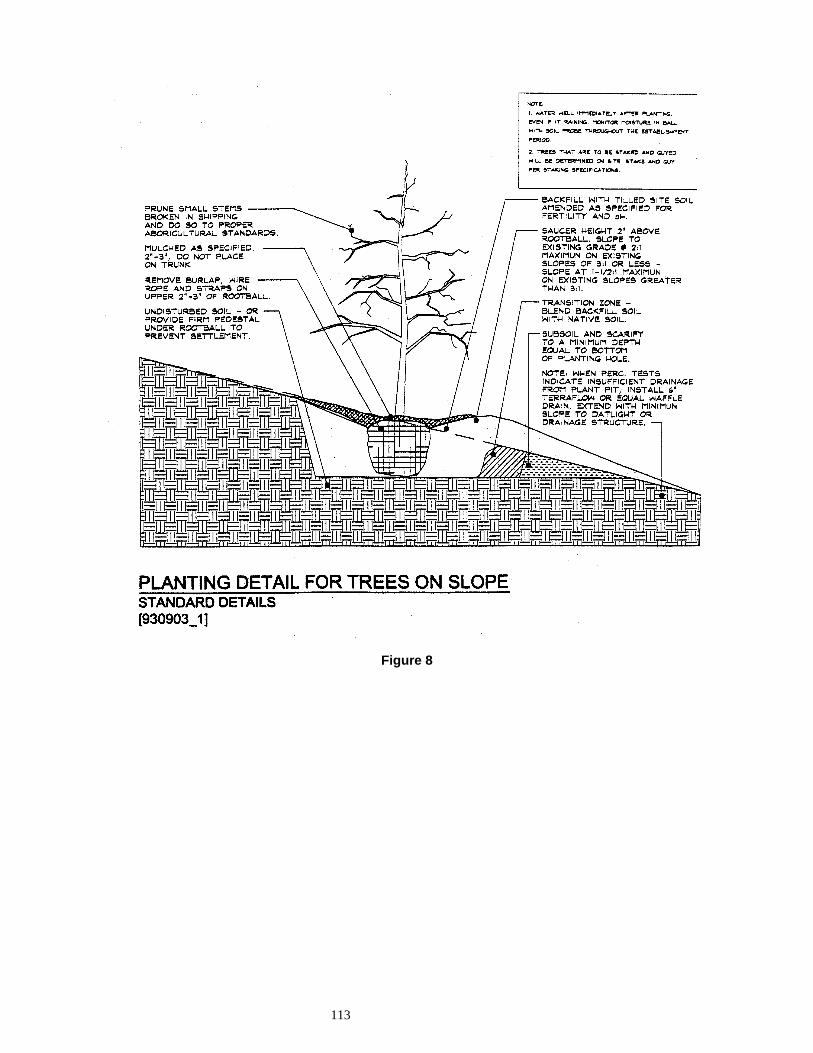
113
Figure 8

114
Figure 9

115
Figure 10

116
Figure 11
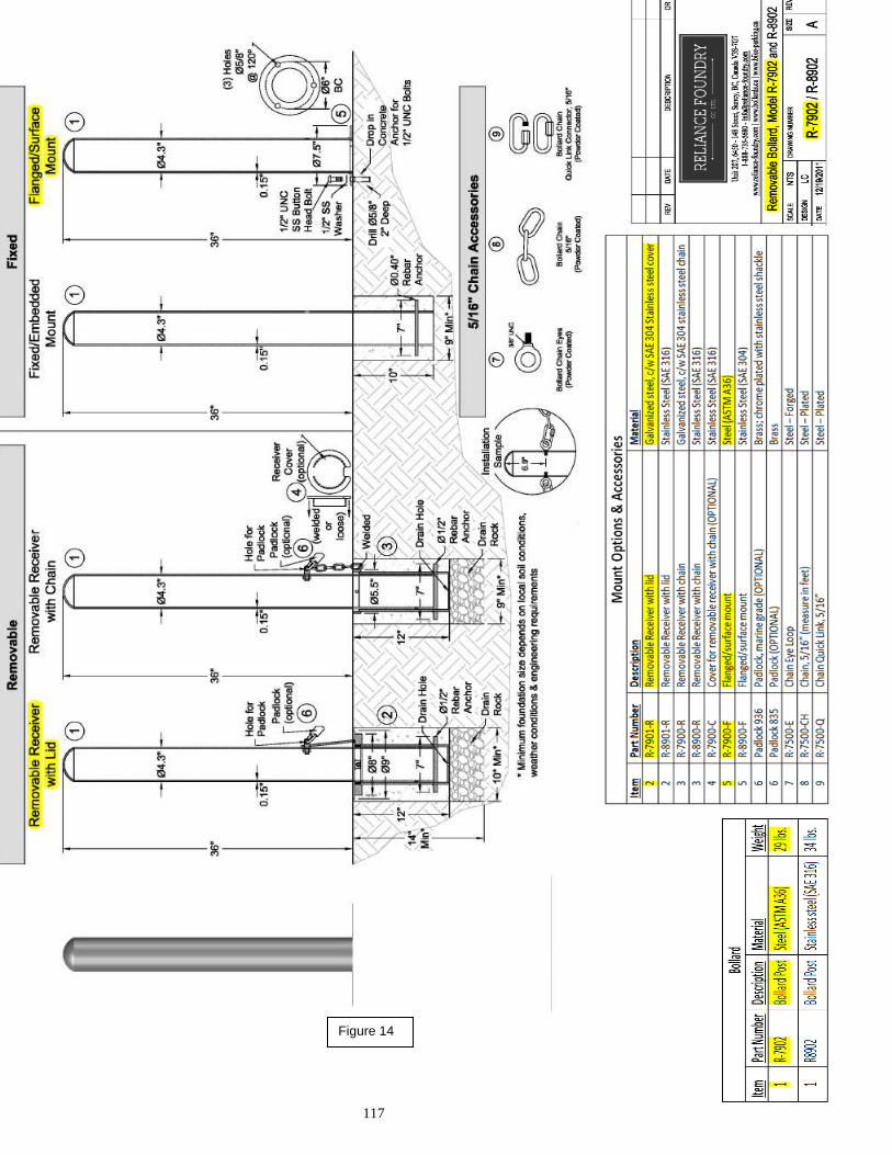
117
Figure 14

118
Figure 15

119
Figure 17

120
SIGNAGE STANDARDS – ALL INCLUSIVE
Figure 18

121
SIGNAGE STANDARD FOR INTERIOR CHANGEABLE TYPE DIRECTORY
Figure 19

122
SIGNAGE STANDARD FOR EXTERIOR BUILDING SIGN
Figure 20

123
Figure 21

124
Figure 22

125
Figure 23

126
Figure 24

127
Figure 25

128
Figure 26

129
Figure 27

130
Figure 28

131
Figure 30

132
Figure 31

133
Figure 32

134
Figure 33
SYMBOLS:

135
Figure 34
DIRECTIONAL ARROWS:
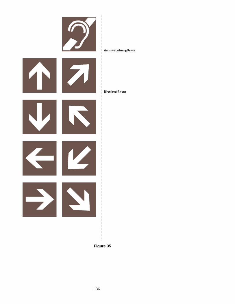
136
Figure 35

137
SIGN TYPE 1:
Figure 36
SIGN TYPE 2:

138
Figure 37
SIGN TYPE 2A:

139
Figure 38
SIGN TYPE 2B:

140
Figure 39
SIGN TYPE 3:

141
Figure 40
SIGN TYPE 3A:

142
Figure 41
SIGN TYPE 3B:

143
Figure 42
SIGN TYPE 4:

144
Figure 43
SIGN TYPE 6:

145
Figure 44
SIGN TYPE 6A

146
Figure 45
SIGN TYPE 8:
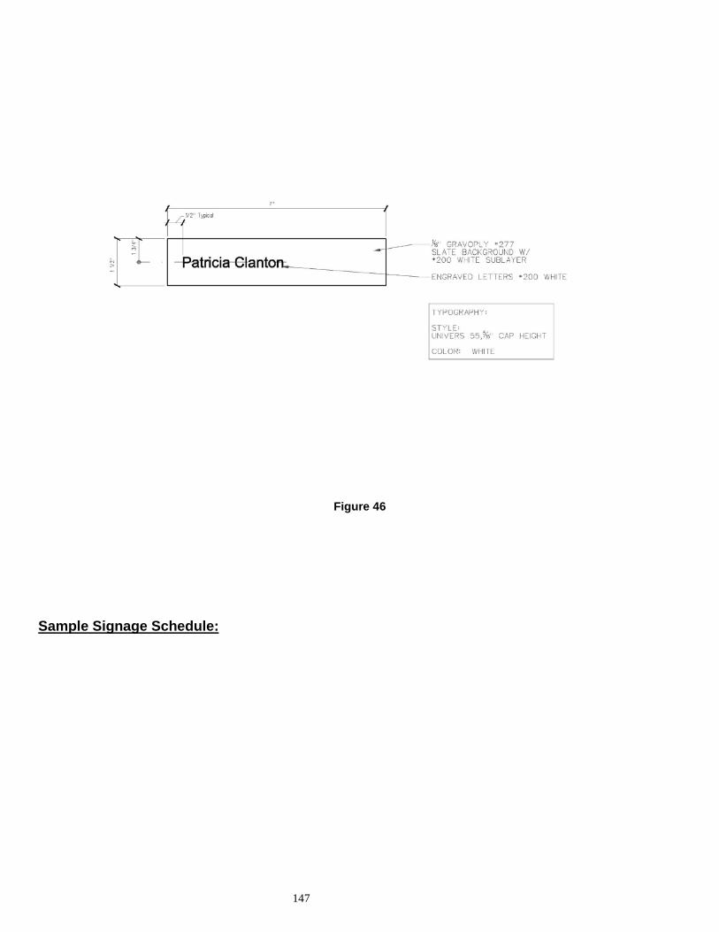
147
Figure 46
Sample Signage Schedule:

148
UNT Chemistry Building - Level 1 Partial Floor Plan
Figure 47

149
Figure 48

150
Figure 49

151
Appendix H: Facilities Planning, Design and Construction CAD Standards (Updated Oct 2012)
UNIVERSITY OF NORTH TEXAS O F F I C E O F F A C I L I T I E S P L A N N I N G , D E S I G N A N D C O N S T R U C T I O N
SEC TI O N F . 2. 0 - CA D S TA N DAR D S MA N UAL
TABLE OF CONTENTS
2.1 Layers List 2.2 Tool Palettes 2.3 Project Drawing File 2.4 Importing FM&C Interiors Titleblock Templates 2.5 Drawing Standards 2.6 AutoCAD Command Aliases
2.1 Layers List

152
Use the following list of approved layers. DO NOT CREATE NEW LAYERS. All layers (A0-A6) correspond to individual drawing sheets. Ex: Everything in your drawing that is being demolished should be on A0 layer and turned on in your viewport in paperspace. All layers A1-A6 should be turned off. As long as you are diligent with layer management from the onset, this will make for simple page setup. If you have questions about what belongs on which layers, consult a Project Manager for assistance.

153
A- Annotations and Existing A6/ E- Elevations & Details NICN- not in contract negations A0- Demo B- (Base) drawing/ Existing A1- Construction C- (Civil) Parking & Road A2- Power & Data L- (Landscape) Plants, Fencing, Irrigation A3- RCP RM- (Risk Management) A4- Finishes Symbols Library- All annotation symbols from palette A5- Furniture NOPLOT- will not print
2.2 Tool Palettes

154
FPD&C has created a custom tool palette for our department use. This palette will ease and expedite the drawing process when used correctly. The contents of this palette shall be used to maintain our CAD standards and it is mandatory that they are used.
1. To find this palette click View a. Tool Palettes
2. If the tool palette does not include tabs/ blocks other than the program default, you will need to adjust the settings by following these steps:
a. Type OP b. In the Files tab, click the plus sign box next to Tool Palettes File Location c. Select file path link and click Browse d. Browse to P:\Fac\FPD&C\_CAD STDS\ToolPalette e. Click Apply and OK
3. You may need to close and restart the AutoCAD program if additional tool palettes are not visible after loading.
Below is a list of all of the tabs that should be in your tool palette when loaded correctly. DO NOT CREATE YOUR OWN SYMBOLS; use those provided within the palette. If a symbol does not exist for a specific circumstance within a project drawing that you are working on, please notify a Project Manager for assistance. Most blocks contain attributes that can be modified simply by double clicking on the symbol once drug into your workspace. Simply double click the block and a dialogue box will appear where you can make the correction. Some blocks contain invisible attributes that cannot be seen on the drawing. The invisible attributes can be extracted into a spread sheet for tracking.
Tool Palette Tabs:
Annotation: AutoCad default Architectural: AutoCad default Hatches and Fills: AutoCad default Tables: AutoCad default ADA Exterior: exterior ramps **Symbols: annotation symbols such as key note bubbles; room number tag; elevation symbol; North arrow; finish block; detail
symbol; wall and window type symbol, etc. ADA Restroom: typicals with required clearances; plumbing fixtures; millwork details ADA Interior: ADA symbol; cane, crutch, walker, wheelchair figures; grab bars and handrails Lights: exterior light elevations; detail of light pole base; bike rack Exterior: AutoCad default **Furniture: typical desk configurations; lab, task, tablet arm chairs; file cabinets; equipment- sink; copier Misc: AutoCad default Layers: UNT logo; approved layers; stamps Millwork: shelf section; base and upper cabinet; reception counter; adjustable shelving Dims, Text: AutoCad default **Power Legend: all power symbols; fire alarm symbols; light switches **RCP Legend: Light fixtures; emergency lights; security; HVAC Typical Office: layouts Macros: AutoCad default ** Most commonly used, see below

155

156
2.3 Project Drawing File

157
P:\Fac\FPD&C\Cadd\RECORD FILES and open the record drawing for the building/ floor where your new project is located. Using Save As, save a copy of the record drawing into the project folder from which you will be actively working. File shall be named according to the file name conventions for active CAD file.
2.4 Importing FM&C Interiors Titleblock Templates
STEP ONE: Position your cursor over one of the tabs at the bottom of the screen – doesn’t matter which one, although there should only be two (Model and Layout1). Right click and select “From Template” from the menu. Navigate to P:\Fac\FPD&C\_CAD STDS\titleblocks and after determining the appropriate size/layout for your project, first import the template file ending with “…ANNO.dwt”. This is your annotation, or title, page for your drawing set.
Once you have imported the annotation template, repeat the steps to import the corresponding
template size for the remainder of the drawing set. When you select the template size a dialogue box will appear Insert Layouts, that has A0, A1, ADA1-3, and Door & Wall. Select all of these layouts and OK. These are layouts that you may not need but are very helpful to bring into your drawing just in case. Whatever you don’t use, you can delete when cleaning up the drawing toward the end of the project.
STEP TWO: Rename your tabs accordingly (AN, A0, A1, A2, A3, A4, A5, A6, etc.) and then update all
titleblock text to include specific project details. Edit all text FIRST on the AN, Ao, A1 tab, and THEN create the appropriate number of copies of the A1 so that all you have to modify on subsequent sheets is the sheet title and sheet number.
To create a copy, right click above the tab you want to make a copy of, and select Move or Copy
from the menu. Then highlight (move to end) and check the box next to Create a Copy at the bottom of the dialog box. Click OK. Repeat as many times as necessary to complete your set.
NOTE: 1/8” scale is the preferred scale for most drawings, but ¼” or ½” can be used if necessary
(for elevations, details, or projects with a smaller area of scope). At the beginning of the project, decide which scale is most appropriate for the size of the project (“size” you will be plotting), then dimension using the correlating dimscale. FM&C18 = 1/8”, FM&C14 = ¼”, and FM&C12 = ½”.
2.5 Drawing Standards

158
Following is a list of standards that need to be followed when preparing a set of construction documents. It is imperative for the sake of efficiency that all drawings be created and maintained in a consistent manner.
P-LINES: When drawing single entities such as doors or pieces of furniture, these should be drawn using the rectangle command or using p-lines. This eliminates random lines floating about in model space and makes it easier and faster to select those entities quickly.
EXPLODE: Do not use the explode tool… EVER! Most blocks can be modified by right-clicking and selecting
Edit Block in Place LAYER Use only the layers listed in your layer manager. If you are unsure of what MANAGEMENT: layer a CAD entity should be placed on, check with one of the Project Managers. If a new layer
needs to be assigned, it will be assigned by a PM. Do not change the layer color, line weight, or line type unless specifically asked to do so by a
Project Manager. The only times this should occur is in the case of lower/upper millwork cabinetry, elevations/details, or various other rare situations. If unsure of how to proceed with differentiating between items on the same layer, check with a Project Manager for clarification/guidance.
SPACE PLANNING & All Record Drawings have floor plates set at coordinates 0,0. During design CONSTRUCTION development, space plans should be drawn within the active CAD file by DRAWINGS: copying the area of project scope above or out to the sides of the floor plate. Space planning
should always be done using the correct layer standards. Upon receiving signature of approval on a space plan, the approved plan should be moved back into correct position within the floor plate.
DRAWING In the process of preparing construction documents, it is the responsibility of each CLEANUP: individual who is working on that file to not only work cleanly, but also to clean up the existing
drawing as you go. Make sure you delete all un-used layouts and space planning options that are not used in the construction documents.
Items that you should be aware of include:
• Corners whose lines don’t meet up/touch • Copying notes without using Ortho to ensure that they align • When drawing squares, rectangles, or other shapes, use P-LINES or the correlating
shape command instead of a series of individual lines • Drawing or leaving what should be one continuous line as several individual line
segments • Use the Solid command to poche walls (instead of Hatch) • Use MText instead of Dtext • Trim overlapping lines • Trim lines at intersecting walls • Use a common pick point when copying the same entity multiple times (i.e. when
copying the “E” label that denotes existing entities, use a common pick point so that the label is inserted at the same location at every occurrence)
• Check all text for grammatical and spelling errors • Delete duplicate entities, such as several lines laying on top of one another, in
order to maintain the integrity of the linetype when plotting ALWAYS DOUBLE-CHECK YOUR OWN WORK!!!

159
2.6 AutoCAD Command Aliases
Keyboard Alias AutoCAD Command A Arc AA Area/ Perimeter BR Break BPOLY Boundary C Circle CH Change CO Copy D Dim Style Manager DC Design Center DAL Dimension Align DDEdit Edit text, including dimension text DDPTYPE Point style dialog box DI Distance DIV Divide DO Donut DT DText E Erase EX Extend F Fillet + F When trimming or extending, type in F to trim/extend with a fence H Hatch HE Hatch Edit I Insert L Line Lead Leader LTS LTScale M Move MI Mirror ML Multiline MT MText O Offset Oops If something was erased accidently OS OSnap P Pan Painter Match Properties PEdit Edit properties of p-lines and/or changes line to p-line PL Poly Line Keyboard Alias AutoCAD Command PO Point POL Polygon PR Properties PU Purge REGEN Regenerate RO Rotate S Stretch SC Scale SP Spell Check SPL Spline ST Text Style TR Trim TR+Enter+Enter All entities become cutting edges TR+Enter+Enter+Shift Toggles between trim and extend TP Tool Palette UN Drawing Units X Explode XC XClip XL XLine (Construction Line) XR XReference Z Zoom F1- HELP F7- GRID ON/OFF F10- POLAR TRACKING ON/OFF F2- COMMAND TEXT WINDOW F8- ORTHO ON/OFF F3- OSNAP ON/OFF F9- SNAP ON/OFF

160
Appendix I: TRANSFORMER SPECIFICATION (Rev. 06/24/14)
LIQUID FILLED PAD MOUNTED TRANSFORMERS Three phase, pad mounted, liquid-filled, distribution type transformer. Standard sizes range from 75 – 5,000 KVA with primary rating from 2,400 to 46,000 V.
1.0 REFERENCES
A. ANSI/IEEE C37.47 - Specifications for Distribution Fuse Disconnection Switches, Fuse Supports, and Current-Limiting Fuses
B. ANSI/IEEE C57.12.00 - General Requirements for Distribution and Power Transformers C. ANSI/IEEE C57.12.26 – Requirements for Distribution Transformers for use with Separable Insulated High-
Voltage Connectors D. ANSI/IEEE C57.12.28 – Switchgear and Transformers, Pad-Mounted Equipment – Enclosure Integrity E. ANSI/IEEE C57.12.34 – Requirements for Pad-Mounted, Compartmental-Type, Self-Cooled, Three-Phase
Distribution Transformers, 2,500 KVA and Smaller: High Voltage, 34,500 GrdY/19,920 Volts and Below; Low Voltage, 480 Volts and Below
F. ANSI/IEEE C57.12.70 - Terminal Markings and Connections for Distribution and Power Transformers G. ANSI/IEEE C57.12.90 – Standard Test Code for Liquid-Immersed Distribution Power, and Regulating
Transformers and Guide for Short-Circuit Testing of Distribution and Power Transformers H. ANSI/IEEE C57.12.91- Terminology for Power and Distribution Transformers I. ANSI/IEEE 386 – Separable Insulated Connector Systems for Power Distribution Systems above 600 V J. ASTM D877 – Test Method for Dielectric Breakdown Voltage of Insulating Liquids Using Disk Electrodes K. NEC 450-23, Less Flammable Insulating Oil L. NEMA TR-1 – Maximum Sound Levels M. DOE: 10 CFR Part 431 - Energy Conservation Program for Commercial Equipment: Distribution Transformers
Energy Conservation Standards; Final Rule; October 12, 2007 N. Factory Mutual Research Corporation – Approval Standard Class 3990
2.0 PRODUCT 2.1 MANUFACTURERS
A. Acceptable Manufacturers:
1. Cooper Power Systems 2. General Electric Company 3. Square D Company
B. Quality Control
1. Company specializing in distribution transformers with five years documented experience. When
requested, an acceptable list of installations with similar equipment shall be provided demonstrating compliance with this requirement.
2.2 PAD MOUNTED DISTRIBUTION TYPE TRANSFORMERS (PRIMARY 13.2 kV)
A. Transformers shall be factory-assembled, three phase, delta-wye configuration, pad mounted, compartmental type, dead front, air-cooled (KNAN) distribution type transformers; ratings as below. All transformers shall be new.
B. Transformers shall be Factory Mutual Approved Code Listed and Labeled by Factory Mutual Research Corporation as meeting the requirements of FMRC Approval Standard Class 3990. Transformers shall be designed and manufactured in accordance with current standards of ANSI and NEMA.
C. Ratings:
1. ____________ KVA 2. ____________Phase

161
3. Frequency 60 Hz 4. Primary Voltage 13,200 V Delta, 95 KV BIL; KV Class 15 KV 5. Secondary Voltage ________________ Wye, 30 KV BIL; KV Class 1.2 KV 6. Taps: Full capacity, two 2½% above normal and two 2½% below normal taps.
D. Coil and Core
1. Transformer shall have copper windings. 2. Isolate core and coil from enclosure using vibration-absorbing mounts. 3. The transformer shall carry its continuous rating with an average winding or temperature rise by
resistance that shall not exceed 65 degrees C. rise, based on an average ambient temperature of 30 degrees C. over 24 hours, with a maximum of 40 degrees C. The insulation system shall allow an additional 12 % kVA output at 65 degree C. average winding temperature rise by resistance, on a continuous basis, without any decrease in normal transformer life.
4. Insulation fluid shall be FR3 less flammable insulation fluid per NEC 450-23. 5. Provide a 5 position tap changer operator, located in one of the compartments, for de-energized
tap-changing operation with pad lockable handle. 6. Transformers shall conform to 2010 standard efficiency levels for liquid immersed distribution
transformers, as specified in Table I.1 of the Department of Energy ruling, 10 CFR Part 431. 7. Sound Levels: Guaranteed sound levels shall not exceed NEMA TR-1. Maximum sound levels.
E. Terminations and Fusing
1. The terminations and equipment shall be arranged for radial feed. 2. The high voltage terminations and equipment shall be dead front and conform to ANSI C57.12.26
requirements. Provide universal type bushing wells for use with elbow terminators and parking stands for mounting accessory equipment. Bushing wells shall be externally clamped. Inserts (feed-thru type) and load break elbows shall be included.
3. Provide a two position, oil-immersed, gang operated, rotary, loadbreak switch with internal fuse link. The switch mechanism shall be spring loaded and the operation shall be independent of operator speed. The switch shall have the following ratings: 200 amps continuous current. Momentary current 15,000 amps symmetrical (10 cycles), 25,000 amps asymmetrical (first peak). Load interrupting 200 amps at 70% power factor.
4. Provide Bay-O-Net type oil immersed fuses in series with oil immersed current limiting fuses to conform to the requirements of Factory Mutual. Provide three (3) spare Bay-O-Net fuses with the transformer.
5. Provide three (3) - 10 kV M.O.V.E deadfront metal oxide varistor elbow arresters for placement in the high voltage compartment connected to the feed-thru inserts.
6. Provide bushing wells, 15 KV, 95 KV BIL feed through inserts (3), lightning arrestors, 15 KV, 95 KV BIL load break inserts, and load breaker elbows.
7. The low voltage bushings shall be molded epoxy and provided with blade type spade terminals with NEMA standard hole spacing arranged for vertical take-off. The low voltage neutral shall be an insulated bushing grounded to the transformer tank by a removable grounding strap. Wye-wye connected transformers shall have the high and low voltage neutrals internally tied with a removable link for testing.
F. Enclosure
1. The transformer(s) shall be compartmental type, self-cooled, tamper resistant and weather protected for
mounting on a pad. There shall be no exposed screws, bolts or other fastening devices that are externally removable.
2. The transformer shall be of the sealed tank construction of sufficient strength to withstand a pressure of 7 psi without permanent distortion. The cover shall be welded, and the fastenings tamper resistant. The transformer will remain effectively sealed for a top oil temperature range of -5° C. to 106° C. When required, corrugate cooling panels or radiators will be provided on the back and sides of the tanks. Construction shall consist of carbon steel plate reinforced with external side-wall braces. All seams and joints shall be continuously welded.
3. Lifting eyes and jacking pads will be provided. 4. The high and low voltage compartments shall be located side-by-side separated by a steel barrier. When

162
facing the transformer, the low voltage compartment shall be on the right. Terminal compartments shall be full height, air filled with individual doors. The high voltage door fastenings shall not be accessible until the low voltage door has been opened. The low voltage door shall have a 3-point latching mechanism with a cabinet handle having provisions for a single padlock. Penta-head cabinet door bolts shall be furnished for the low voltage door. The doors shall be equipped with lift-off type stainless steel hinges and door stops to hold the doors open when working in the compartments. The front sill of the compartment shall be removable to allow the transformer to be rolled or skidded into position over conduit stubs. ANSI tank grounding provisions shall be furnished in each compartment.
5. The enclosure shall have suitable outdoor paint finish. Topcoat shall be Bell Green (Munsell 7GY 3.29/1.5).Paint shall meet factory standard ANSI C57.12.28 for outdoor service and shall be applied in accordance with the manufacturers written instructions. Provide written certification by a registered professional Engineer that the paint and application comply with the ANSI Standard Specified.
6. Each radiator assembly shall be individually welded and receive a quality control pressurized check for leaks. The entire tank assembly shall receive a similar leak test before tanking. A final six-hour leak test shall be performed after the transformer is tanked, welded and completed to ensure that there are not leaks before shipment. Include the test results in the certified test report.
G. Accessories
1. Liquid level gauge, 2. Dial type thermometer 3. Pressure vacuum gauge 4. Drain/sampling and filter valve, 5. Ground connectors 6. Schrader type, upper fill valve. 7. Pressure relief valve. 8. Provisions for lifting and provisions for jacking. 9. Base designed for skidding or rolling in two directions. 10. Manufacturer’s standard, automatic, pressure relief device, that automatically reseals after operation. 11. Instruction nameplate. 12. Welded-on main tank cover and bolted handhole in cover or bolted cover. 13. Non-corroding metal identification name plate with black lettering. Information to be provided during shop
drawing review. 14. Insulated caps and insulated parking bushings for each bushing well. 15. Cabinet accessories pocket on compartment door for spare fuses.
H. Labels
1. Notifications: Danger: High Voltage decal 2. Notifications: DOE Efficiency Compliant decal 3. Notifications: Non-PCB decal 4. Certification: Factory Mutual (FM) approved, outdoor installation
I. Testing
The following factory tests shall be made on each transformer. Tests shall be in accordance with the latest revision of ANSI Test Code C57.12.90 and/or NEMA TR1:
1. Resistance measurements of all windings on the rated voltage connection and at the tap extremes of
each unit. 2. Ratio tests on the rated voltage connection and on all tap connections. 3. Polarity and phase-rotation tests on the rated voltage connections. 4. No-load loss at rated voltage on the rated voltage connection. 5. Exciting current and rated voltage on the rated voltage connection. 6. Percent Impedance, core loss, winding loss, excitation current, at rated current on the rated voltage
connection and on the tap extremes of each unit. 7. Temperature Test or tests shall be made on each unit. Tests shall not be required when there is
available a record of a temperature test on an essentially duplicate unit. 8. Applied potential test. 9. Induced potential tests. 10. Leak test to check for leaks at welds and bushings.

163
11. Results of the above tests shall be submitted in the form of certified test report for each transformer sealed by a registered professional engineer attesting that the tests were personally witnessed.
12. Furnish a certified copy of the transformer loss test report sealed by a registered professional Electrical Engineer. The report shall certify the efficiency of each transformer measured in accordance with ANSI Standard C57.12.90-1973.

164
APPENDIX J: UNT Facilities Attic Stock Procedures (rev.03/29/11)
For new buildings it is required that a secured storage area within the building be identified as part of the building program. A full complement of attic stock materials should be provided by the contractor at close-out. For building renovations, due to a lack of available storage, attic stock items are to be identified early on in the design phase to determine critical needs. Generally these will be items to support equipment rooms and will not include architectural materials unless specialty non- university standard finishes are specified. The attached check list should be filled out by Facilities identifying these items. In no case will remnant construction materials (such as small pieces or opened packages) be retained as attic stock. Contractor shall provide UNT Facilities with a written list including amounts as part of the close-out document package. All attic stock items should be clearly labeled with the date, construction project and stock information. Sample attic stock check list:
o Architectural materials (new buildings or specialty areas only) o Extra ceiling materials o Extra cans of paint o Sealants o Masonry materials o Flooring o Wall covering o Paint
o Fire Protection o Sprinkler heads
o HVAC o Spare filters o Spare drive belts & motors o Fusible links
o Electrical o Wiring devices o Fixture lenses & bulb covers o lamps
o Plumbing o Filters o Trim

165
"X"
indicates to be
included in
contract
Specification Section
Material
Provided Attic Stock
087100
Door Hardware
Special Tools
Maintenance Tools
093000
Tiling
Tile and Trim Units - 3% of installed
Grout - 3% of installed
095113
Acoustical Panel Ceilings
Ceiling Tile, Grid, and Clips: 2% of installed
095133
Acoustical Metal Pan Ceilings
Ceiling Tile, Grid, and Clips: 2% of installed
096513
Resilient Base and Accessories
Wall Base: 10 ft. for every 500 ft. of Each Type, Color, Pattern and Size Used
096519
Resilient Tile Flooring
Floor Tile: 1 box for every 50 boxes
of Each Type, Color, and Pattern Used
096813
Tile Carpeting
Carpet Tile: 5% of Each Type Used,
Not Less Than 10 sq. yd.
096816
Sheet Carpeting
Carpet Rolls: 5% of installed
097713
Panel Fabric Wall and Ceiling Systems
5% of Gross Wall and Ceiling Area
of Each Color Pattern and Type Used
099113
Exterior Painting
Paint: 5% of Applied, Not Less than (1) Gallon
099123
Interior Painting
Paint: 5% of Applied,
Not Less than (1) Gallon
099646
Intumescent Painting
Paint: 5% of Applied, Not Less than (1) Gallon
102226
Operable Partitions
Panel Finish Material: Two sides of Two Panels
122413
Roller Window Shades
Roller Shades: 5% of Installed,
but No Fewer Than 2 Units, for Each Size, Color, and Shadeband
211313
Wet-Pipe Sprinkler Systems
Spare Heads and Wrenches in Cabinets
224700
Drinking Fountains & Water Coolers
Filter Cartridges: 10% of Installed, not <1 Each Type
232123
Hydronic Pumps
Seals: (1) for Each Pump
233300
Air Duct Accessories
Fusible Links: 10% of Installed
233416
Centrifugal HVAC Fans
Belts: 1 Set for Each Belt-Driven Unit
233423
HVAC Power Ventilators
Belts: 1 Set for Each Belt-Driven Unit
Motor Puller for Fans >5 HP
233600
Air Terminal Units
Pan-Powered-Unit Filters: (1) Spare Filter for Each Filter Installed

166
234100
Particulate Air Filtration
Filters: (2) Sets for Each Filter Bank
237313
Modular Indoor Central-StationAir-
Handling Units
Filters: (2) Sets for Each AHUBelts: (1) Set for Each
AHU Fan
238126
Split-System Air-Conditioners
Filters: (1) Set / Unit Fan Belts: (1) Set / Unit
238219
Fan Coil Units
Filters: (2) Spare for Each Installed Belts: (2) Spare for Each Installed
261300
Medium-Voltage Switchgear
Touch-Up Paint Can: Munsell Green 9999-058
271500
Communications Horizontal Cabling
Patch-Panel Units, Connecting Blocks
Device Plates Multiuser Telecom Outlets: (1) Each Type
283111
Digital, Addressable Fire-Alarm System
Lamps, Smoke Detectors, Fire Detectors, Detector
Bases, Keys and Tools, Notification Appliances, Fuses
321413.19
Permeable Interlocking
Concrete Pavement
(1) Palette of Each Color and Type Used
328400
Planting Irrigation
(5) Parts Each of Irrigation Components