the video mesh: a data structure for image-based video editing
TRANSCRIPT

Computer Science and Artificial Intelligence Laboratory
Technical Report
m a s s a c h u s e t t s i n s t i t u t e o f t e c h n o l o g y, c a m b r i d g e , m a 0 213 9 u s a — w w w. c s a i l . m i t . e d u
MIT-CSAIL-TR-2009-062 December 16, 2009
The Video Mesh: A Data Structure for Image-based Video EditingJiawen Chen, Sylvain Paris, Jue Wang, Wojciech Matusik, Michael Cohen, and Fredo Durand

The Video Mesh: A Data Structure for Image-based Video Editing
Jiawen Chen1 Sylvain Paris2 Jue Wang2 Wojciech Matusik2 Michael Cohen3 Frédo Durand1
1Computer Science and Artificial Intelligence LaboratoryMassachusetts Institute of Technology
2Adobe Systems, Inc. 3Microsoft Research
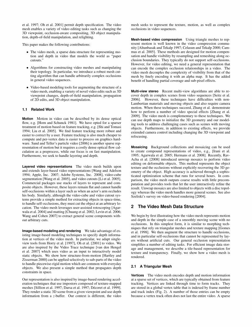
Input video
Video Mesh
Texture Alpha
“Paper Cutout” view
Applications
Depth of Field Manipulation
Compositing
Viewpoint Change
Figure 1: The video mesh data structure represents the structural information in an input video as a set of deforming texture mapped trianglesaugmented with mattes. The mesh has a topology that resembles a “paper cutout”. This representation enables a number of special effectsapplications such as depth of field manipulation, object insertion, and change of 3D viewpoint.
Abstract
This paper introduces the video mesh, a data structure for represent-ing video as 2.5D “paper cutouts.” The video mesh allows inter-active editing of moving objects and modeling of depth, which en-ables 3D effects and post-exposure camera control. The video meshsparsely encodes optical flow as well as depth, and handles occlu-sion using local layering and alpha mattes. Motion is described bya sparse set of points tracked over time. Each point also stores adepth value. The video mesh is a triangulation over this point setand per-pixel information is obtained by interpolation. The user ro-toscopes occluding contours and we introduce an algorithm to cutthe video mesh along them. Object boundaries are refined with per-pixel alpha values.
The video mesh is at its core a set of texture mapped triangles, weleverage graphics hardware to enable interactive editing and render-ing of a variety of effects. We demonstrate the effectiveness of ourrepresentation with a number of special effects including 3D view-point changes, object insertion, and depth-of-field manipulation.
Keywords: video editing, triangle mesh, compositing, featuretracking, optical flow
1 Introduction
We introduce the video mesh, a new representation that encodes themotion, layering, and 3D structure of a video sequence in a unifieddata structure. The video mesh can be viewed as a 2.5D “papercutout” model of the scene as shown in Figure 1. For each frame ofa video sequence, the video mesh is composed of a triangle meshtogether with texture and alpha (transparency). Depth informationis encoded with a per-vertex z coordinate, while motion is handledby linking vertices in time (for example, based on feature track-ing). The mesh can be cut along occlusion boundaries and alphamattes enable the fine treatment of partial occlusion. It supportsa more general treatment of visibility than traditional layer-basedmethods [Wang and Adelson 1994] and can handle self-occlusionswithin a layer such as the actor’s hand in Figure 1. The per-vertexstorage of depth and the rich occlusion representation makes it pos-sible to extend image-based modeling into the time dimension. Fi-nally, the video mesh is based on texture-mapped triangles to enablefast processing on graphics hardware.
We leverage off-the-shelf technology when possible to provideuser-assisted tools for the creation of a video mesh from an inputvideo. Tracking software provides motion information. Rotoscop-ing [Agarwala et al. 2004] and matting (e.g., [Chuang et al. 2002;Levin et al. 2006; Wang and Cohen 2007]) enable fine handlingof occlusion. A combination of structure-from-motion [Hartleyand Zisserman 2000] and interactive image-based modeling [Horry
et al. 1997; Oh et al. 2001] permit depth specification. The videomesh enables a variety of video editing tasks such as changing the3D viewpoint, occlusion-aware compositing, 3D object manipula-tion, depth-of-field manipulation, and relighting.
This paper makes the following contributions:
• The video mesh, a sparse data structure for representing mo-tion and depth in video that models the world as “papercutouts.”
• Algorithms for constructing video meshes and manipulatingtheir topology. In particular, we introduce a robust mesh cut-ting algorithm that can handle arbitrarily complex occlusionsin general video sequences.
• Video-based modeling tools for augmenting the structure of avideo mesh, enabling a variety of novel video edits such as 3Dviewpoint changes, depth-of-field manipulation, propagationof 2D edits, and 3D object manipulation.
1.1 Related Work
Motion Motion in video can be described by its dense opticalflow, e.g. [Horn and Schunck 1981]. We have opted for a sparsertreatment of motion based on feature tracking, e.g. [Shi and Tomasi1994; Liu et al. 2005]. We find feature tracking more robust andeasier to correct by a user. Feature tracking is also much cheaper tocompute and per-vertex data is easier to process on graphics hard-ware. Sand and Teller’s particle video [2006] is another sparse rep-resentation of motion but it requires a costly dense optical flow cal-culation as a preprocess, while our focus is on fast manipulation.Furthermore, we seek to handle layering and depth.
Layered video representations The video mesh builds uponand extends layer-based video representations [Wang and Adelson1994; Apple, Inc. 2007; Adobe Systems, Inc. 2008], video-cubesegmentation [Wang et al. 2005], and video cutouts [Li et al. 2005].Commercial packages use stacks of layers to represent and com-posite objects. However, these layers remain flat and cannot handleself-occlusions within a layer such as when an actor’s arm occludeshis body. Similarly, although the video-cube and video cutout sys-tems provide a simple method for extracting objects in space-time,to handle self-occlusions, they must cut the object at an arbitrary lo-cation. The video mesh leverages user-assisted rotoscoping [Agar-wala et al. 2004] and matting [Chuang et al. 2002; Levin et al. 2006;Wang and Cohen 2007] to extract general scene components with-out arbitrary cuts.
Image-based modeling and rendering We take advantage of ex-isting image-based modeling techniques to specify depth informa-tion at vertices of the video mesh. In particular, we adapt single-view tools from Horry et al. [1997], Oh et al. [2001] to video. Weare also inspired by the Video Trace technique [van den Hengelet al. 2007] which uses video as an input to interactively modelstatic objects. We show how structure-from-motion [Hartley andZisserman 2000] can be applied selectively to sub-parts of the videoto handle piecewise-rigid motion which are common with everydayobjects. We also present a simple method that propagates depthconstraints in space.
Our representation is also inspired by image-based rendering accel-eration techniques that use impostors composed of texture-mappedmeshes [Sillion et al. 1997; Darsa et al. 1997; Décoret et al. 1999].They render a static 3D scene from a given viewpoint and use depthinformation from a z-buffer. Our context is different, the video
mesh seeks to represent the texture, motion, as well as complexocclusions in video sequences.
Mesh-based video compression Using triangle meshes to rep-resent motion is well known in the video compression commu-nity [Altunbasak and Tekalp 1997; Celasun and Tekalp 2000; Cam-mas et al. 2005]. These methods are designed for motion compen-sation and handle visibility by resampling and remeshing along oc-clusion boundaries. They typically do not support self-occlusions.However, for video editing, we need a general representation thatcan encode the complex occlusion relationships in a video. Thevideo mesh decouples the complexity of visibility from that of themesh by finely encoding it with an alpha map. It has the addedbenefit of handling partial coverage and sub-pixel effects.
Multi-view stereo Recent multi-view algorithms are able to re-cover depth in complex scenes from video sequences [Seitz et al.2006]. However, these techniques have difficulties with non-Lambertian materials and moving objects and also require cameramotion. When these techniques succeed, Zhang et al. demonstratehow to perform a number of video special effects [Zhang et al.2009]. The video mesh is complementary to these techniques. Wecan use depth maps to initialize the 3D geometry and our model-ing tools to address challenging cases such as scenes with movingobjects. Furthermore, in addition to existing effects, we provideextended camera control including changing the 3D viewpoint andrefocusing.
Mosaicing Background collections and mosaicing can be usedto create compound representations of video, e.g., [Irani et al.1995; Agarwala et al. 2005; Hermans et al. 2008]. Recently, Rav-Acha et al. [2008] introduced unwrap mosaics to perform videoediting on deformable objects. This method represents the objecttexture and the occlusions without explicitly recovering the 3D ge-ometry of the object. High accuracy is achieved through a sophis-ticated optimization scheme that runs for several hours. In com-parison, the video mesh outputs coarse results with little precom-putation and provides tools that let the user interactively refine theresult. Unwrap mosaics are also limited to objects with a disc topol-ogy whereas the video mesh handles more general scenes. See alsoSzeliski’s survey on video-based rendering [2004].
2 The Video Mesh Data Structure
We begin by first illustrating how the video mesh represents motionand depth in the simple case of a smoothly moving scene with noocclusions. In this simplest form, it is similar to morphing tech-niques that rely on triangular meshes and texture mapping [Gomeset al. 1998]. We then augment the structure to handle occlusions,and in particular self-occlusions that cannot be represented by lay-ers without artificial cuts. Our general occlusion representationsimplifies a number of editing tasks. For efficient image data stor-age and management, we describe a tile-based representation fortexture and transparency. Finally, we show how a video mesh isrendered.
2.1 A Triangular Mesh
Vertices The video mesh encodes depth and motion informationat a sparse set of vertices, which are typically obtained from featuretracking. Vertices are linked through time to form tracks. Theyare stored in a global vertex table that is indexed by frame numberand track index (Fig. 2). A number of those entries can be emptybecause a vertex track often does not last the entire video. A sparse

class VideoMesh {
// vertex list per frame
List<Vertex>[nFrames] vertexTable;
// face list per frame
List<Face>[nFrames] faceTable;
TextureData texture;
Camera[nFrames] cameraPath;
}
class Vertex {
// current position in screen space
Vector2f position;
float z; // depth (optional)
// Original position used as texture
// coordinates. Equal to position if
// the video has not been edited.
Vector2f originalPosition;
float originalZ;
// TRACKED, S_VIRTUAL, or T_VIRTUAL
enum VertexType type;
// Accessors use the vertexTable.
// Can return null for temporal
// virtual vertices.
// predecessor in time
Vertex getPrevious();
// successor in time
Vertex getNext();
}
class Face {
int[3] vertexIndices;
// tiles occupied by this face
List<TextureTile> tiles;
// used for temporal edits
int tOriginal;
}
Figure 2: Basic video mesh data structures.
representation such as a hash table can be used for efficiency.
A vertex stores its position in the original video, which is used toreference textures that store the pixel values and alpha. The currentposition of a vertex can be modified for editing purposes (e.g. toperform motion magnification [Liu et al. 2005; Wang et al. 2006]),and we store it in a separate field. A vertex has access to its positionin the next and previous frames through accessors that return thevertex in the same track at the next or previous frame index in thevertex table (Fig. 2).
Vertices also have a field to store depth information, which canbe specified through a number of tools which we describe in Sec-tion 3.2. Depth information is encoded with respect to a cameramatrix that is specified per frame.
Faces We use a Delaunay triangulation over each frame to definethe faces of the Video Mesh. Each triangle is texture-mapped withthe pixel values from the original video, with texture coordinatesdefined by the original position of its vertices. The textures canalso be edited to enable various video painting and compositingeffects. Each face stores a list of pointers to texture tiles to enablethe treatment of multiple layers, as described below.
The triangulations of consecutive frames are mostly independent.While it is desirable that the topology be as similar as possible be-tween frames to generate a continuous motion field, this is not astrict requirement. We only require vertices, not faces, to be linkedin time. The user can also force edges to appear in the triangula-tion by adding line constraints. For instance, we can ensure thata building is accurately represented by the video mesh by aligningthe triangulation with its contours.
Motion To illustrate with a concrete example, consider a simplemanipulation such as motion magnification that warps the video.One starts by tracking features over time. For this simple example,we assume that all tracks last the entire video sequence and thatthere is no occlusion or layering. Each frame is then triangulated tocreate faces. The velocity of a vertex can be accessed by querying
its successor and predecessor and taking the difference. A simplescaling of displacement [Liu et al. 2005] or more complex temporalprocessing [Wang et al. 2006] yields the new position of each ver-tex. The final image for a given frame is obtained by rendering eachtriangle with the vertices at the new location but with texture coor-dinates at the original position, indexing the original frames. Thisis essentially equivalent to triangulation-based morphing [Gomeset al. 1998].
The triangulation defines a piecewise-linear interpolation of thesparse information stored at vertices. This is implicitly applied todepth and motion to obtain dense motion fields and depth maps.While this yields satisfying estimates in smooth regions, disconti-nuities require more attention, as described below.
2.2 Occlusion
Real-world scenes have occlusions, which are always the most chal-lenging aspect of motion treatment. Furthermore, vertex tracks canappear or disappear over time because of, for instance, occlusion orloss of contrast. The video mesh handles these cases by introduc-ing virtual vertices and duplicating triangles to store informationfor both foreground and background parts.
Consider first the case of vertices that appear or disappear over time.Since we rely on the predecessor and successor to extract motioninformation, we introduce temporal virtual vertices at both ends ofa vertex track. Like normal vertices, they store a position, which isusually extrapolated from the adjacent frames but can also be fine-tuned by the user.
Real scenes also contain spatial occlusion boundaries. In mesh-based interpolation approaches, a triangle that overlaps two sceneobjects with different motions yields artifacts when motion is inter-polated. While these artifacts can be reduced by refining the trian-gulation to closely follow edges, e.g., [Cammas et al. 2005], thissolution can significantly increase geometric complexity and doesnot handle soft boundaries. Instead, we take an approach inspiredby work in mesh-based physical simulation [Molino et al. 2004].At occlusion boundaries, where a triangle partially overlaps bothforeground and background layers, we duplicate the face into fore-ground and background copies, and add spatial virtual vertices tocomplete the topology. To resolve per-pixel coverage, we computea local alpha matte to disambiguate the texture (see Figure 3). Sim-ilar to temporal virtual vertices, their spatial counterparts also storeposition information that is extrapolated from their neighbors. Wealso extrapolate a motion vector at these points and create temporalvirtual vertices in the adjacent past and future frames to representthis motion. Topologically, the foreground and background copiesof the video mesh are locally disconnected: information cannot di-rectly propagate across the boundary.
When an occlusion boundary is not a closed loop, it ends at a sin-gularity called a cusp. The triangle that the cusp belongs to getsduplicated like any other boundary triangle and the alpha handlesfine-scale occlusion. We describe the topological construction ofcuts and cusps in Section 3.1.
The notion of occlusion in the video mesh is purely local and en-ables self-occlusion within a layer, just like how a 3D polygonalmesh can exhibit self-occlusion. Occlusion boundaries do not needto form closed contours. We simply cut the mesh and duplicate tri-angles locally. Depth ordering is specified through the per-vertex zinformation.

FOREGROUND
color map
node type and depth
alpha matte
frame and mesh
BACKGROUND
color map
node type and depth
alpha matte
BACKGROUND
color map
node type and depth
alpha matte
FOREGROUND
color map
node type and depth
alpha matte
tracked
(z = 1)
virtual (z = 1)
virtual
(z = 1)
virtual
(z = 2)
tracked (z = 2)
tracked
(z = 2)
Figure 3: Occlusion boundaries are handled by duplicating faces.Each boundary triangle stores a matte and color map. Duplicatedvertices are either tracked, i.e., they follow scene points, or virtualif their position is inferred from their neighbors.
2.3 Tile-Based Texture Storage
At occlusion boundaries, the video mesh is composed of severaloverlapping triangles and a pixel in the image plane can be as-signed several values, typically one for the foreground and one forthe background. While simple solutions such as the replication ofthe entire frame are possible, we present a tile-based approach thatseeks to strike a balance between storage overhead and flexibility.
Replicating the entire video frame for each layer would be wastefulsince few faces are duplicated and in practice, we would run outof memory for all but the shortest video sequences. Another pos-sibility would be generic mesh parameterization [Hormann et al.2007], but the generated atlas would likely introduce distortionssince these methods have no knowledge of the characteristics of thevideo mesh, such as its rectangular domain and preferred viewpoint.
Tiled texture We describe a tile-based storage scheme whichtrades off memory for rendering efficiency—in particular, it doesnot require any mesh reparameterization. The image plane is di-vided into large blocks (e.g., 128×128). Each block contains a listof texture tiles that form a stack. Each face is assigned its natu-ral texture coordinates; that is, with (u,v) coordinates equal to the(x,y) image position. If there is already data stored at this location(for instance, when adding a foreground triangle and its backgroundcopy already occupies the space in the tile), we move up in the stackuntil we find a tile with free space. If a face spans multiple blocks,we allocate into each stack using the same strategy: a new tile iscreated within a stack if there is no space in the existing tiles.
To guarantee correct texture filtering, each face is allocated a one-pixel-wide margin so that bilinear filtering can be used. If a faceis stored next to its neighbor, then this margin is already present.Boundary pixels are only necessary when two adjacent faces arestored in different tiles. Finally, tiles also overlap by two-pixels inscreen space to ensure correct bilinear filtering for faces that spanmultiple tiles.
The advantages of a tile-based approach is that overlapping facesrequire a new tile instead of duplicating the entire frame. Similarly,local modifications of the video mesh such as adding a new bound-ary impact only a few tiles, not the whole texture. Finally, tilesalso enable data to be stored without distortion relative to the inputvideo.
2.4 Rendering
The video mesh is, at its core, a collection of texture-mapped tri-angles and is easy to render using modern graphics hardware. Wehandle transparency by rendering the scene back-to-front using al-pha blending, which is sufficient when faces do not intersect. Wehandle faces that span several tiles with a dedicated shader that ren-ders them once per tile, clipping the face at the tile boundary. Re-call that we have added a one-pixel margin around the faces so thatwe can use bilinear filtering to maintain visual quality even afteroperations such as a change of viewpoint. To achieve interactiverendering performance, we cache tiles in texture memory as a sin-gle large atlas (e.g., 4096×4096), storing tiles as subregions. Thiscaching strategy also enables efficient rendering when we accessdata across multiple frames, such as when we perform space-timecopy-paste operations. Finally, when the user is idle, we prefetchnearby frames in the background into the cache to enable playbackafter seeking to a random frame.
3 Video Mesh Operations
The video mesh supports a number of creation and editing opera-tors. This section presents the operations common to most applica-tions, while we defer application-specific algorithms to Section 4.
3.1 Cutting the mesh along occlusions
The video mesh data structure supports a rich model of occlusion aswell as interactive creation and manipulation. For this, we need theability to cut the mesh along user-provided occlusion boundaries.We use splines to specify occlusions [Agarwala et al. 2004], andonce cut, the boundary can be refined using image matting [Chuanget al. 2002; Levin et al. 2006; Wang and Cohen 2007]. In thissection, we focus on the topological cutting operation of a videomesh given a set of splines.
A boundary spline has the following properties:
1. It specifies an occlusion boundary and is non-intersecting.
2. It is directed, which locally separates the image plane intoforeground and background.
3. It can be open or closed. A closed spline forms a loop that de-fines an object detached from its background. An open splineindicates that two layers merge at an endpoint called a cusp.
Ordering constraints In order to create a video mesh whosetopology reflects the occlusion relations in the scene, the initial flatmesh is cut front-to-back. We organize the boundary splines intoa directed graph where nodes correspond to splines and a directededge between two splines indicates that one is in front of another.We need this ordering only at T-junctions, when a spline a endsin contact with another spline b. If a terminates on the foregroundside of b, we add an edge a→ b, otherwise we add b→ a. Since thesplines represent the occlusions in the underlying scene geometry,the graph is guaranteed to be acyclic. Hence, a topological sort onthe graph produces a front-to-back partial ordering from which wecan create layers in order of increasing depth. For each spline, wewalk from one end to the other and cut each crossed face accordingto how it is traversed by the spline. If a spline forms a T-junctionwith itself, we start with the open end; and if the two ends form T-junctions, we start at the middle of the spline (Fig. 7). This ensuresthat self T-junctions are processed top-down.

Four configurations To cut the mesh along the splines, we dis-tinguish the four possible configurations:
1. If a face is fully cut by a spline, that is, the spline does not endinside, we duplicate the face into foreground and backgroundcopies. Foreground vertices on the background side of thespline are declared virtual. We attach the foreground face tothe uncut and previously duplicated faces on the foregroundside. We do the same for the background copy (Fig. 4).
2. If a face contains a T-junction, we first cut the mesh using thespline in front as in case 1. Then we process the back spline inthe same way, but ensure that at the T-junction, we duplicatethe background copy (Fig. 5). Since T-junctions are formed byan object in front of an occlusion boundary, the back spline isalways on the background side and this strategy ensures thatthe topology is compatible with the underlying scene.
3. If a face is cut by a cusp (i.e., by a spline ending inside it), wecut the face like in case 1. However, the vertex opposite thecut edge is not duplicated; instead, it is shared between thetwo copies (Fig. 6).
4. In all the other cases where the face is cut by two splines thatdo not form a T-junction or by more than two splines, we sub-divide the face until we reach one of the three cases above.
a) flat mesh and boundary spline b) cut video mesh with matted layerslat memesh and boundarmesh and bound
Figure 4: Cutting the mesh with a boundary spline. The cut facesare duplicated. The foreground copies are attached to the adjacentforeground copies and uncut faces. A similar rule applies to thebackground copies. Blue vertices are real (tracked), white verticesare virtual.
Motion estimation Cutting the mesh generates spatial virtual ver-tices without successors or predecessors in time. We estimate theirmotion by diffusion from their neighbors. For each triangle withtwo tracked vertices and a virtual vertex, we compute the transla-tion, rotation, and scaling of the edges with the two tracked vertices.We apply the same transformation to the virtual vertex to obtain itsmotion estimate. If the motion of a virtual vertex can be evaluatedfrom several faces, we find a least-squares approximation to its mo-tion vector. We use this motion vector to create temporal virtualvertices in the previous and next frame. This process is iteratedas a breadth-first search until the motion of all virtual vertices arecomputed.
Boundary propagation Once we have motion estimates for allspatial virtual vertices in a frame, we can use the video mesh toadvect data. In particular, we can advect the control points of theboundary spline to the next (or previous) frame. Hence, once theuser specifies the occlusion boundaries at a single keyframe, as long
(a) frame (c) video mesh
topology
(b) video mesh
and splines
Figure 5: Cutting the mesh with two splines forming a T-junction.We first cut according to the non-ending spline, then according tothe ending spline.
(a) cusp seen in image plane
with a spline ending
(b) video mesh topology
Figure 6: Cutting the mesh with a cusp. This case is similar to thenormal cut (Fig. 4) except that the vertex opposite to the cut edge isshared between the two copies.
as the topology of occlusion boundaries does not change, we haveenough information to build a video mesh over all frames. We de-tect topology changes when two splines cross and ask the user toadjust the splines accordingly. In practice, the user needs to edit5 to 10% of the frames, which is comparable to the technique ofAgarwala et al. [2004].
3.2 Depth Estimation
After cutting the video mesh, it is already possible to infer a pseudo-depth value based on the foreground/background labeling of thesplines. However, for a number of video processing tasks, con-tinuous depth values enable more sophisticated effects.
Static camera: image-based modeling For scenes that feature astatic camera with moving foreground objects, we provide simpletools inspired from the still photograph case [Horry et al. 1997; Ohet al. 2001] to model a coarse geometric model of the background.The ground tool lets the user define the ground plane from the hori-zon line. The vertical object tool enables the creation of verticalwalls and standing characters by indicating their contact point withthe ground.
The focal length tool retrieves the camera field of view from twoparallel or orthogonal lines on the ground. This proxy geometry issufficient to handle complex architectural scenes as demonstrated

(a) simple self T-junction (b) double self T-junction
Figure 7: If a spline forms a T-junction with itself (a), we startfrom the open end (shown with a star) and process the faces inorder toward the T-junction. If a spline forms two T-junctions withitself (b), we start in between the two T-junctions and process thefaces bidirectionally.
in the supplemental video.
Moving camera: user-assisted structure-from-motion Forscenes with a moving camera, we build on structure-from-motionto simultaneously recover a camera path as well as the 3D positionof scene points. For the camera, we retrieve its position and ori-entation at each time frame and a fixed focal length for the wholesequence. In general, there might be several objects moving inde-pendently. The user can indicate rigid objects by selecting regionsdelineated by the splines. We recover their depth and motion in-dependently using structure-from-motion [Hartley and Zisserman2000] and register them in a global coordinate system by aligningto the camera path which does not change. We use an off-the-shelfstructure-from-motion package [2d3 2008]. We let the user cor-rect misalignments by specifying constraints, typically by pinninga vertex to a given position.
Even with a coarse video mesh, these tools allow a user to create amodel that is reasonably close to the true 3D geometry. In addition,after recovering the camera path, adding additional vertices is easyby clicking on the same point in only 2 frames. The structure-from-motion solver recovers its 3D position by minimizing reprojectionerror over all the cameras.
3.3 Inpainting
We triangulate the geometry and inpaint the texture in hidden partsof the scene in order to render 3D effects such as changing the view-point without revealing holes. We have implemented several simplestrategies to handle common configurations.
Mesh For closed holes that typically occur when an object oc-cludes the background, we list the mesh edges at the border of thehole and fill in the mesh using constrained Delaunay triangulationwith the border edges as constraints.
When a boundary is occluded, which happens when an object par-tially occludes another, we observe the splines delineating the ob-ject. An occluded border generates two T-junctions which we de-tect. We add an edge between the corresponding triangles and usethe same strategy as above with Delaunay triangulation.
Texture For large holes that are typical of missing backgrounds(Figure 1), we use a background collection [Szeliski 1996]. Afterinfilling the geometry of the hole, we use the motion defined by themesh to search forward and backward in the video for unoccludedpixels. A background collection is effective when there is moderatecamera or object motion and can significantly reduce the number ofmissing pixels. We fill the remaining pixels by isotropically diffus-ing data from the edge of the hole.
When the missing region is textured and stable, such as on the shirtof an actor (Figure 1), we modify Efros and Leung texture synthe-sis [1999] to search only in the same connected component as thehole, ensuring that only similar patches are copied.
Finally, for architectural scenes where textures are more regular andboundaries are straight lines, we proceed as Khan et al. [2006] andmirror the neighboring data to fill in the missing regions.
Although these tools are simple, they achieve satisfying results inour examples since the regions where they are applied are not themain focus of the scene. If more accuracy is needed, one can usededicated mesh repair [Lévy 2003] and inpainting [Bertalmio et al.2000] algorithms.
(a) original viewpoint
(b) new viewpoint
Figure 8: The occlusion handling and per-vertex information en-coded in the video mesh enable viewpoint changes. Top: originalframe. Bottom: camera moved forward and left toward the river-bank. Note the proper occlusion between the riverbank, building,and Notre-Dame.
4 Results
We illustrate the use of the video mesh on a few practical appli-cations. These examples exploit the video mesh’s accurate scenetopology and associated depth information to create a variety of 3Deffects. The results are available in the companion video.
Depth of field manipulation We can apply effects that dependon depth such as enhancing a camera’s depth of field or inserting anobject into a video sequence. To approximate a large aperture cam-era with a shallow depth of field, we construct a video mesh with3D information and render it from different viewpoints uniformlysampled over a synthetic aperture, keeping a single plane in focus.

(a) focus on foreground
(b) focus on background
Figure 9: Compositing and depth of field manipulation. We repli-cated the character from the original video and composited him.The depth information stored in the video mesh naturally achievesthe required foreshortening. We also perform a rack focus usingsynthetic depth of field.
Since the new viewpoints may reveal holes, we use our inpaintingoperator to fill both the geometry and texture. For manipulating de-focus blur, inpainting does not need to be accurate. This approachsupports an arbitrary location for the focal plane and an arbitraryaperture. We demonstrate in the companion video the rack focuseffect which is commonly used in movies: the focus plane sweepsthe scene to draw the viewer’s attention to subjects at various dis-tances (Fig. 9). This effect can be previewed in real time by sam-pling 128 points over the aperture. We render a high-quality versionwith 1024 samples at about 2 Hz.
Object insertion and manipulation Copy-and-paste is supportedby the video mesh. The user first delineates an object with splinesand then the object can be replicated or moved anywhere by copy-ing the corresponding faces. In addition, the depth structure of thevideo mesh enables occlusions between the newly added objectsand the scene while per-pixel transparency makes it possible to ren-der antialiased edges. This is shown in the colonnade sequencewhere the copied characters are occluded by the pillars. The usercan also specify that the new object should be in contact with thescene geometry. In this case, the depth of the object is automaticallyprovided according to the location in the image, in the same spiritas the Photo Clip Art system proposed by Lalonde et al. [2007] forstatic scenes. We further develop this idea by exploiting the motiondescription provided by the video mesh to ensure that the copiedobjects consistently move as the camera viewpoint changes. Thisfeature is shown in the copier sequence of the companion video.
(a) wide �eld of view,
camera close to the subject
(b) narrow �eld of view,
camera far from the subject
Figure 10: Vertigo effect enabled by the 3D information in thevideo mesh. We zoom in and at the same time pull back. Thiskeeps the foreground character at the same size but modifies theperspective of the background.
When we duplicate an animated object several times, we offset thecopies in time to prevent unrealistically synchronized movements.
We can also use transparency to render volumetric effects. In thecompanion video, we demonstrate the insertion of smoke. To obtainvolumetric attenuation and occlusion that depends on the geometry,we render 10 offset layers of semi-transparent animated smoke.
Change of 3D viewpoint With our modeling tools (Sec. 3.2) wecan generate proxy geometry that enables 3D viewpoint changes.We demonstrate this effect in the companion video and in Figure 8.In the colonnade and Notre-Dame sequences, we can fly the cam-era through the scene even though the input viewpoint was static.In the copier sequence, we apply a large modification to the cam-era path to view the copier from the side. Compared to existingtechniques such as Video Trace [van den Hengel et al. 2007], thevideo mesh can handle moving scenes as shown with the copier.The scene geometry also allows for change of focal length, whichin combination with change of position, enables the vertigo effect,a.k.a. dolly zoom, in which the focal length increases while thecamera moves backward so that the object of interest keeps a con-stant size (Fig. 10). Resolution can be a limiting factor in areaswhere there is significant magnification. However, we believe thatin many cases, the additional freedom brought by repositioning thecamera after the shot makes up for the loss of resolution.

(a) original frame
(b) relit with fog and shadows
(best viewed on screen)
Figure 11: Relighting a daytime scene to depict night. Left: orig-inal video frame. Right: Scene relit with simulated lights, fog, andshadows cast by composited characters.
Relighting and participating media We use the 3D geometry en-coded in the video mesh for relighting. In the companion video,we transform the daylight colonnade sequence into a night scene(Fig. 11). We use the original pixel value as diffuse material color,position light sources where light bulbs are visible, and add volu-metric fog. We render the scene using raytracing to simulate shad-ows and participating media [Pharr and Humphreys 2004].
Performance We implemented our prototype in DirectX 10. Weran all our experiments on an Intel Core i7 920 at 2.66 GHz with8 MB of cache, and a NVIDIA GeForce GTX 280 with 1 GB ofvideo memory. Memory usage varies between 1 GB to 4 GB de-pending on the sequence, which is typical for video editing ap-plication. To handle long video sequences, we use a multi-levelvirtual memory hierarchy over the GPU, main memory, and diskwith background prefetching to seamlessly access and edit the data.With the exception of offline raytracing for the fog simulation,and high-quality depth of field effects that require rendering eachframe 1024 times, all editing and rendering operations are interac-tive (> 15 Hz).
Discussion Although our approach enables useful effects, it isnot without limitations. First, since we rely on off-the-shelf com-ponents, we inherit their shortcomings. As mentioned earlier, userssometimes have to pinpoint a vertex to correct misalignment thatmay appear in the structure-from-motion output. We also foundthat the publicly available matting techniques [Wang and Cohen
2007; Levin et al. 2006] were challenged by some of our sequencesas can be seen for instance in the colonnade example. More directlyrelated to our approach, the video mesh is a coarse data structure:high-frequency motion and thin features would be difficult to accu-rately represent. For instance, the video mesh would not representblades of grass flowing in the wind well, although we believe thatother techniques would also have difficulties. For the same reason,the video mesh cannot represent finely detailed geometry such asa bas-relief on a wall. In this case, the bas-relief would appear asa texture on a smooth surface which may be sufficient in a numberof cases but not if the bas-relief is the main object of interest. Tosummarize, the video mesh enables effects that combine motion,depth, and video, and works best with objects and motion that areof medium scale or larger.
5 Conclusion
We have presented the video mesh, a data structure to representvideo sequences and whose creation is assisted by the user. Therequired effort to build a video mesh is comparable to rotoscop-ing but the benefits are higher since the video mesh offers a richmodel of occlusion and enables complex effects such as depth-aware compositing and relighting. Furthermore, the video meshnaturally exploits graphics hardware capabilities to provide interac-tive feedback to users. We believe that video meshes can be broadlyused as a data structure for video editing.
References
2D3, 2008. boujou 4.1. http://www.2d3.com/.
ADOBE SYSTEMS, INC., 2008. After effects cs4.
AGARWALA, A., HERTZMANN, A., SALESIN, D. H., AND SEITZ,S. M. 2004. Keyframe-based tracking for rotoscoping and ani-mation. ACM Transactions on Graphics 23, 3, 584–591.
AGARWALA, A., ZHENG, K. C., PAL, C., AGRAWALA, M., CO-HEN, M., CURLESS, B., SALESIN, D. H., AND SZELISKI, R.2005. Panoramic video textures. ACM Transactions on Graphics24, 3 (Aug.), 821–827.
ALTUNBASAK, Y., AND TEKALP, A. 1997. Occlusion-adaptive,content-based mesh design and forward tracking. IEEE Trans-actions on Image Processing 6, 9 (Sep), 1270–1280.
APPLE, INC., 2007. Motion 3.0.2.
BERTALMIO, M., SAPIRO, G., CASELLES, V., AND BALLESTER,C. 2000. Image inpainting. In Proceedings of the ACM SIG-GRAPH conference, ACM, 417–424.
CAMMAS, N., PATEUX, S., AND MORIN, L. 2005. Video codingusing non-manifold mesh. In Proceedings of the 13th EuropeanSignal Processing Conference.
CELASUN, I., AND TEKALP, A. 2000. Optimal 2-d hierarchicalcontent-based mesh design and update for object-based video.IEEE Transactions on Circuits and Systems for Video Technol-ogy 10, 7 (Oct), 1135–1153.
CHUANG, Y.-Y., AGARWALA, A., CURLESS, B., SALESIN, D.,AND SZELISKI, R. 2002. Video matting of complex scenes.ACM Trans. Graph 21, 3, 243–248.
DARSA, L., SILVA, B. C., AND VARSHNEY, A. 1997. Navigatingstatic environments using image-space simplification and mor-phing. In SI3D, 25–34, 182.

DÉCORET, X., SILLION, F. X., SCHAUFLER, G., AND DORSEY,J. 1999. Multi-layered impostors for accelerated rendering.Comput. Graph. Forum 18, 3, 61–73.
EFROS, A. A., AND LEUNG, T. K. 1999. Texture synthesis bynon-parametric sampling. In IEEE International Conference onComputer Vision, 1033–1038.
GOMES, J., DARSA, L., COSTA, B., AND VELHO, L. 1998.Warp-ing and morphing of graphical objects. Morgan Kaufmann Pub-lishers Inc., San Francisco, CA, USA.
HARTLEY, R., AND ZISSERMAN, A. 2000. Multiple View Geom-etry in Computer Vision. Cambridge University Press, June.
HERMANS, C., VANAKEN, C., MERTENS, T., REETH, F. V., AND
BEKAERT, P. 2008. Augmented panoramic video. ComputerGraphics Forum 27, 2 (Apr.), 281–290.
HORMANN, K., LÉVY, B., AND SHEFFER, A. 2007. Mesh param-eterization: Theory and practice. In ACM SIGGRAPH CourseNotes. ACM.
HORN, B., AND SCHUNCK, B. 1981. Determining Optical Flow.Artificial Intelligence 17, 1-3, 185–203.
HORRY, Y., ANJYO, K., AND ARAI, K. 1997. Tour into the pic-ture: Using a spidery mesh interface to make animation froma single image. In Proceedings of SIGGRAPH 97, ComputerGraphics Proceedings, Annual Conference Series, 225–232.
IRANI, M., ANANDAN, P., AND HSU, S. 1995. Mosaic based rep-resentations of video sequences and their applications. In ICCV,605–611.
KHAN, E. A., REINHARD, E., FLEMING, R., AND BUELTHOFF,H. 2006. Image-based material editing. ACM Transactions onGraphics 25, 3 (July). Proceedings of the ACM SIGGRAPHconference.
LALONDE, J.-F., HOIEM, D., EFROS, A., ROTHER, C., WINN,J., AND CRIMINISI, A. 2007. Photo clip art. ACM Transactionson Graphics 26, 3 (July). Proceedings of the ACM SIGGRAPHconference.
LEVIN, A., LISCHINSKI, D., AND WEISS, Y. 2006. A ClosedForm Solution to Natural Image Matting. Proceedings of the2006 IEEE Computer Society Conference on Computer Visionand Pattern Recognition-Volume 1, 61–68.
LÉVY, B. 2003. Dual domain extrapolation. ACM Transactionson Graphics 22, 3 (July). Proceedings of the ACM SIGGRAPHconference.
LI, Y., SUN, J., AND SHUM, H.-Y. 2005. Video object cut andpaste. ACM Transactions on Graphics 24, 3, 595–600.
LIU, C., TORRALBA, A., FREEMAN, W. T., DURAND, F., AND
ADELSON, E. H. 2005. Motion magnification. ACM Transac-tions on Graphics 24, 3, 519–526.
MOLINO, N., BAO, Z., AND FEDKIW, R. 2004. A virtual nodealgorithm for changing mesh topology during simulation. ACMTransactions on Graphics 23, 3, 385–392.
OH, B. M., CHEN, M., DORSEY, J., AND DURAND, F. 2001.Image-based modeling and photo editing. In Proceedings of theACM SIGGRAPH conference.
PHARR, M., AND HUMPHREYS, G. 2004. Physically Based Ren-dering: From Theory to Implementation. August.
RAV-ACHA, A., KOHLI, P., ROTHER, C., AND FITZGIBBON, A.2008. Unwrap mosaics: a new representation for video editing.ACM Transactions on Graphics 27, 3, 17:1–17:11.
SAND, P., AND TELLER, S. 2006. Particle video: Long-rangemotion estimation using point trajectories. In Proceedings of theComputer Vision and Pattern Recognition Conference, IEEE.
SEITZ, S. M., CURLESS, B., DIEBEL, J., SCHARSTEIN, D., AND
SZELISKI, R. 2006. A comparison and evaluation of multi-viewstereo reconstruction algorithms. In Proceedings of the Com-puter Vision and Pattern Recognition Conference, IEEE, 519–528.
SHI, J., AND TOMASI, C. 1994. Good features to track. ComputerVision and Pattern Recognition, 1994. Proceedings CVPR’94.,1994 IEEE Computer Society Conference on, 593–600.
SILLION, F., DRETTAKIS, G., AND BODELET, B. 1997. Ef-ficient impostor manipulation for real-time visualization of ur-ban scenery. Computer Graphics Forum (Proc. EUROGRAPH-ICS’97) 16, 3, 207–218.
SZELISKI, R. S. 1996. Video mosaics for virtual environments.IEEE Computer Graphics and Applications 16, 2 (March), 22–30.
SZELISKI, R. S. 2004. Video-based rendering. In Vision, Model-ing, and Visualization, 447.
VAN DEN HENGEL, A., DICK, A., THORMÄHLEN, T., WARD, B.,AND TORR, P. H. S. 2007. Videotrace: rapid interactive scenemodelling from video. ACM Transactions on Graphics 26, 3,86:1–86:5. Proceedings of the ACM SIGGRAPH conference.
WANG, J. Y. A., AND ADELSON, E. H. 1994. Representing mov-ing images with layers. IEEE Transactions on Image Processing3, 5, 625–638.
WANG, J., AND COHEN, M. 2007. Optimized color sampling forrobust matting. In Proceedings of the IEEE CVPR, IEEE.
WANG, J., BHAT, P., COLBURN, R. A., AGRAWALA, M., AND
COHEN, M. F. 2005. Interactive video cutout. ACM Transac-tions on Graphics 24, 3, 585–594.
WANG, J., DRUCKER, S., AGRAWALA, M., AND COHEN, M.2006. The cartoon animation filter. ACMTransactions on Graph-ics 25, 3, 1169–1173.
ZHANG, G., DONG, Z., JIA, J., WAN, L., WONG, T., AND BAO,H. 2009. Refilming with depth-inferred videos. IEEE Transac-tions on Visualization and Computer Graphics 15, 5, 828–840.
