thermocenter tc40/100 usermanual - cole-parmer · user manual thermocenter tc160, 240, 400 ......
TRANSCRIPT

- 1 - Copyright© SalvisLab / Edition 191107
Thermocenter TC160/240/400 User Manual
swis
s m
ade

User Manual Thermocenter TC160, 240, 400
DECLARATION OF CONFORMITY ................................................................................................................. 4
IMPORTANT INFORMATION........................................................................................................................... 5 QUICK INFORMATION FOR SERVICE.................................................................................................................... 5
TECHNICAL DATA SHEET .............................................................................................................................. 6 TECHNICAL DATA’S FROM THE OVENS................................................................................................................ 6
INTRODUCTION ............................................................................................................................................... 7 OVERVIEW ....................................................................................................................................................... 7 APPLICATIONS.................................................................................................................................................. 7 CONTROLLER ................................................................................................................................................... 7 SAFETY............................................................................................................................................................ 7
GETTING STARTED......................................................................................................................................... 8 PARTS DELIVERED ............................................................................................................................................ 8 INSTALL REQUIREMENTS ................................................................................................................................... 8 INSTALLING ...................................................................................................................................................... 8 CLEANING ........................................................................................................................................................ 8
SYSTEM COMPONENTS ................................................................................................................................. 9
CONTROLLER................................................................................................................................................ 10 KEYPAD & DISPLAY ........................................................................................................................................ 10
OPERATING.................................................................................................................................................... 11 HOW TO INTERPRET DISPLAYS DESCRIBED IN THIS MANUAL... ............................................................................ 11 MAIN MENU OVERVIEW................................................................................................................................... 12 1 MAIN MENU TEMP & OPTIONS...................................................................................................................... 13 2 MAIN MENU PROGRAM................................................................................................................................. 15 2.1 MENU PROGRAM START ........................................................................................................................... 16 2.2 MENU PROGRAM NEW .............................................................................................................................. 17 2.3 MENU PROGRAM EDIT .............................................................................................................................. 20 2.4 MENU PROGRAM DELETE.......................................................................................................................... 22 2.5 MENU PROGRAM PRINT ............................................................................................................................ 22 3 MAIN MENU CONFIGURATION ....................................................................................................................... 23 4 MENU SERVICE MODE ................................................................................................................................. 24
OPERATING DISPLAYS ................................................................................................................................ 25 GENERAL ....................................................................................................................................................... 25 5 OPERATING DISPLAY: MANUAL MODE DELAYED START ................................................................................. 25 6 STATUS DISPLAY: NORMAL MODE RUNNING ................................................................................................. 25 7 STATUS DISPLAY: PROGRAM MODE DELAYED PROGRAM START .................................................................... 26 8 STATUS DISPLAY: PROGRAM MODE PROGRAM RUNNING ............................................................................... 26 9 CANCEL A RUNNING PROCESS BY ESC KEY .................................................................................................. 26 10 MESSAGES AND ERRORS ........................................................................................................................... 27
PRINTER OPERATION................................................................................................................................... 28 CONNECTING A PRINTER................................................................................................................................. 28
APPENDIX A................................................................................................................................................... 29 MENU STRUCTURE & INPUT FIELDS................................................................................................................. 29
APPENDIX B................................................................................................................................................... 30 WIRING DIAGRAMM ......................................................................................................................................... 30
APPENDIX C................................................................................................................................................... 31 DRAWING THERMOCENTER TC 160................................................................................................................. 31
- 2 - Copyright© SalvisLab / Edition 191107
APPENDIX D....................................................................................................................................................32 DRAWING THERMOCENTER TC 240 .................................................................................................................32
APPENDIX E....................................................................................................................................................33 DRAWING THERMOCENTER TC 400 .................................................................................................................33
APPENDIX F ....................................................................................................................................................34 DRAWING SPARE PARTS..................................................................................................................................34
APPENDIX G ...................................................................................................................................................35 SPARE PART NUMBERS ...................................................................................................................................35
Copyright© SalvisLab / Edition 191107 - 3 -
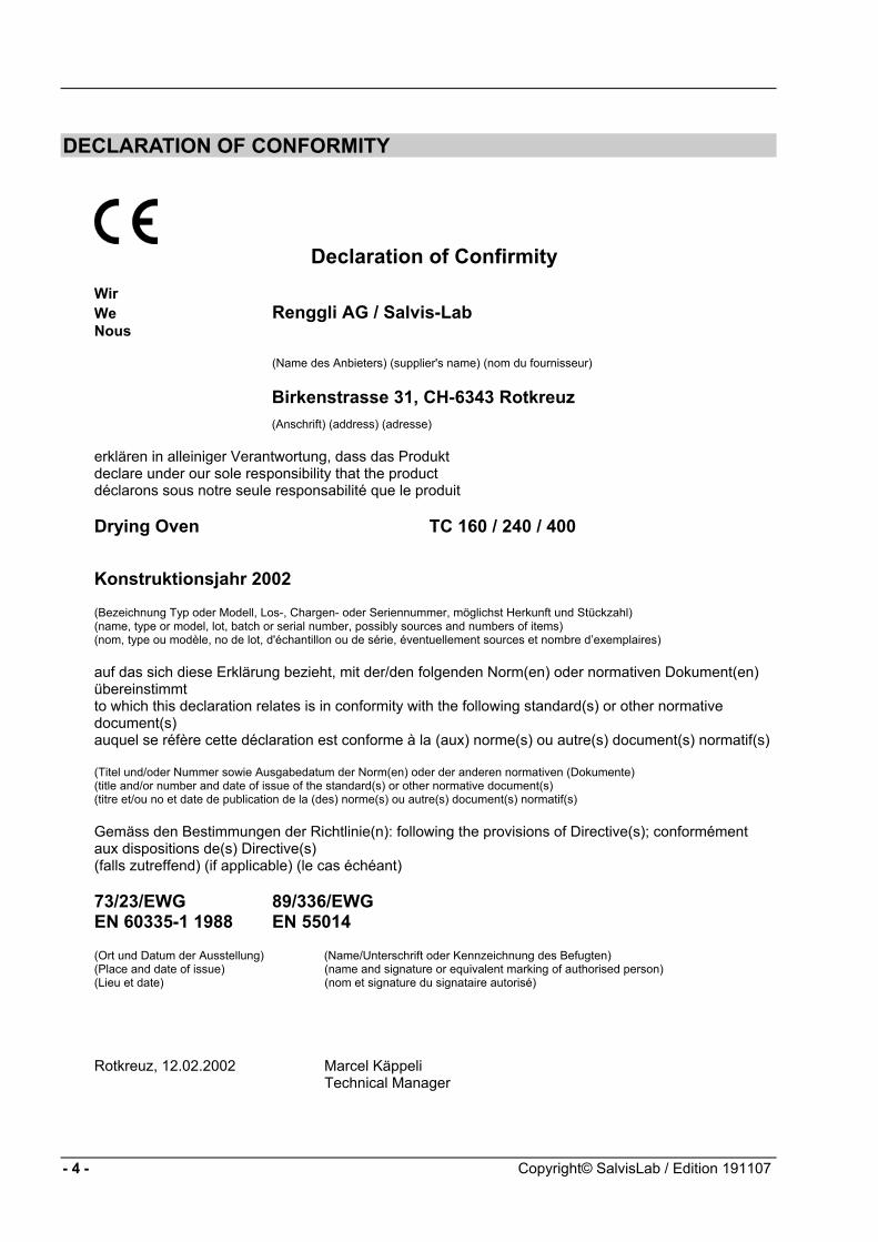
DECLARATION OF CONFORMITY
Declaration of Confirmity
Wir We Renggli AG / Salvis-Lab Nous (Name des Anbieters) (supplier's name) (nom du fournisseur)
Birkenstrasse 31, CH-6343 Rotkreuz (Anschrift) (address) (adresse)
erklären in alleiniger Verantwortung, dass das Produkt declare under our sole responsibility that the product déclarons sous notre seule responsabilité que le produit Drying Oven TC 160 / 240 / 400
Konstruktionsjahr 2002 (Bezeichnung Typ oder Modell, Los-, Chargen- oder Seriennummer, möglichst Herkunft und Stückzahl) (name, type or model, lot, batch or serial number, possibly sources and numbers of items) (nom, type ou modèle, no de lot, d'échantillon ou de série, éventuellement sources et nombre d’exemplaires) auf das sich diese Erklärung bezieht, mit der/den folgenden Norm(en) oder normativen Dokument(en) übereinstimmt to which this declaration relates is in conformity with the following standard(s) or other normative document(s) auquel se réfère cette déclaration est conforme à la (aux) norme(s) ou autre(s) document(s) normatif(s) (Titel und/oder Nummer sowie Ausgabedatum der Norm(en) oder der anderen normativen (Dokumente) (title and/or number and date of issue of the standard(s) or other normative document(s) (titre et/ou no et date de publication de la (des) norme(s) ou autre(s) document(s) normatif(s) Gemäss den Bestimmungen der Richtlinie(n): following the provisions of Directive(s); conformément aux dispositions de(s) Directive(s) (falls zutreffend) (if applicable) (le cas échéant) 73/23/EWG 89/336/EWG EN 60335-1 1988 EN 55014 (Ort und Datum der Ausstellung) (Name/Unterschrift oder Kennzeichnung des Befugten) (Place and date of issue) (name and signature or equivalent marking of authorised person) (Lieu et date) (nom et signature du signataire autorisé)
Rotkreuz, 12.02.2002 Marcel Käppeli Technical Manager
- 4 - Copyright© SalvisLab / Edition 191107
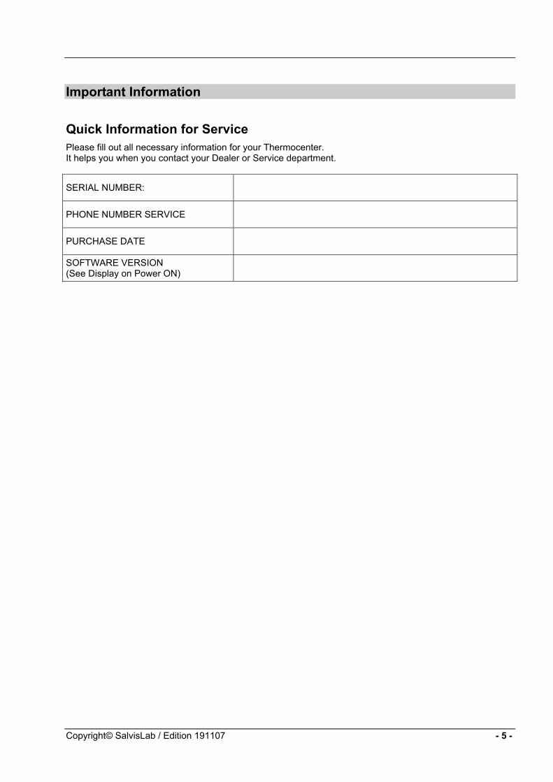
Important Information
Quick Information for Service Please fill out all necessary information for your Thermocenter. It helps you when you contact your Dealer or Service department.
SERIAL NUMBER:
PHONE NUMBER SERVICE
PURCHASE DATE
SOFTWARE VERSION (See Display on Power ON)
Copyright© SalvisLab / Edition 191107 - 5 -
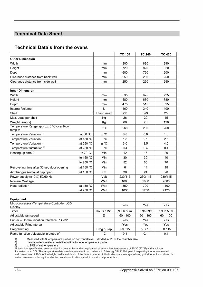
Technical Data Sheet
Technical Data’s from the ovens TC 160 TC 240 TC 400 Outer Dimension Width mm 800 890 990 Height mm 720 820 920 Depth mm 680 720 900 Clearance distance from back wall mm 250 250 250 Clearance distance from side wall mm 250 250 250 Inner Dimension Width mm 535 625 725 Height mm 580 680 780 Depth mm 475 515 695 Internal Volume L 160 240 400 Shelf Stand./max 2/8 2/9 2/9 Max. Load per shelf Kg 26 20 15 Weight (empty) Kg 66 78 120 Temperature Range approx. 5 °C over Room temp to °C 260 260 260
Temperature Variation 1) at 50 °C ± °C 0.8 0.8 1.0 Temperature Variation 1) at 150 °C ± °C 1.8 2.1 2.5 Temperature Variation 1) at 250 °C ± °C 3.0 3.5 4.0 Temperature fluctuation 2) at 250 °C ± °C 0.4 0.4 0.4 Heating up time 3) to 70°C Min 12 16 20 to 150 °C Min 30 30 40 to 250 °C Min 52 60 70 Recovering time after 30 sec door opening at 150 °C Min 6 14 18 Air changes (exhaust flap open) at 150 °C x/h 30 24 20 Power supply (±10%) 50/60 Hz Volt 230/115 230/115 230/115 Nominal Wattage Watt 1600 1800 2000 Heat radiation at 150 °C Watt 550 790 1100
at 250 °C Watt 1035 1250 2120 Equipment Microprocessor -Temperature Controller LCD Display Yes Yes Yes
Timer Hours / Min. 999h 59m 999h 59m 999h 59m Adjustable fan speed % 60 - 100 60 – 100 60 – 100 Printer – Communication Interface RS 232 Yes Yes Yes Adjustable Print Interval Yes Yes Yes Programming Prog./ Step 50 / 15 50 / 15 50 / 15 Ramp function adjustable in steps of °C 0.1 0.1 0.1
1) Measured with 3 temperature probes on horizontal level / divided in 1/3 of the chamber size 2) maximum temperature deviation in time for one temperature probe 3) to 98% of set temperature All technical specification are specified for units with standard equipment at an ambient temperature of 25 °C (77 °F) and a voltage fluctuation of ±10 %. The temperature data are determinated in accordance to following DIN 12880, part 2 respecting the recommended wall clearances of 10 % of the height, width and depth of the inner chamber. All indications are average values, typical for units produced in series. We reserve the right to alter technical specifications at all times without prior notice.
- 6 - Copyright© SalvisLab / Edition 091107
Introduction
Overview The THERMOCENTER are ovens with forced air and an intelligent control of fan-speed in a range between 0-100%. The control of ramping functions allows fast and accurate heating up procedure and therefore more applications available to users Microprocessor-controller with enhanced Fuzzy-Logic - Allows precise ramping of temperature as well as an excellent reproduction of temperature distribution in the chamber. Special Insulation - Less heat loss. Saves energy and costs. Ambient temperature of housing surface Robust Swiss quality design – Made even for scientific applications Work Chambers are of stainless steel and are provided with fully adjustable chromium plated rod shelves. The chambers have well radiused corners for easy cleaning. Exterior is of textured powder coated mild steel.
Applications The THERMOCENTER is an extremely versatile oven. It can be used Research & Development, Quality Control as well industrial applications. Some examples: Drying and sterilization applications in scientific as well as industrial usage suit well for this oven. A must when precise temperature distribution and a high accuracy are needed. Examples of usage : Color fastness test for textiles, Ageing test for plastics and foils, Quality control of electronic circuits, Food analysis, Dry sterilization in hospitals Note: The Thermocenter ovens are not built to use as ovens for drying substances which are explosible or let free explosible gases during the drying process.
Controller Fuzzy-Logic microprocessor controller with digital alphanumeric LCD-Display, real time clock, variable fan speed and temperature ramp. Intelligent Fan-Speed control IntelliFan - Wide range of temperature ramping functions. More user application. In combination with Fuzzy-logic gives you an excellent stability of temperature distribution and accuracy of programmed ramp. Brilliant LCD Display for user-dialog and easy to operate keypad for fast programming and operating. User dialog with controller is displaying your local language. Up to five languages can be selected. Easy to operate and programming with EasyMenu It allows the storage of 50 programs and 15 program steps (a step = a ramp, a temperature, a fan-speed and a dwell time=Hold Time). The programs remain stored in memory even without external power (battery buffered). Holding Time (dwell time) 0 - 999h 59m The real time clock allows a process to be started at any time – i.e.: on January 6, 2002 at 5 30 in the morning. RS-232 interface. All data can be protocolled with a printer or computer.
Safety DIN 12880 class 3.1 In case of over-temperature, a built in safety controller as a back-up circuit takes over the control of the heating and will shutdown the oven. There is also an additional mechanical over-temperature device which shuts down the oven High quality accurate PT 100 temperature sensors. Superior “Swiss Made” manufacturing quality according ISO9001
Copyright© SalvisLab / Edition 091107 - 7 -

Getting Started
Parts delivered Your System will be delivered with following Parts: 1 Thermocenter Unit 2 Shelves 1 Power Cord 1 User Manual
Install requirements Ensure that following conditions are met before you install the system. Electric power connection as per type plate on inside of the door must meet your power connector. For 230 V, 50/60 Hz min For 115 V, 50/60 Hz min The ambient temperature is min. +5° C ... max. 35° C (+40° F ... 95° F) Leave at least 10cm space between system and walls or benches.
Installing Place shelf in appropriate position. Plug cord Close door. Switch power on Display shows current Firmware Version see Power On Sequence To start oven or program it see Chapter Operating Menus
Cleaning To clean the system use mild detergents. No Acid or similar detergents should be used.
- 8 - Copyright© SalvisLab / Edition 091107

System Components
1 Controller 2 Door Handle 3 RS232 Connector (rear) 4 Fan 5 Door Lock 6 Shelf
3
1
2
5 6
4
Copyright© SalvisLab / Edition 091107 - 9 -
Controller
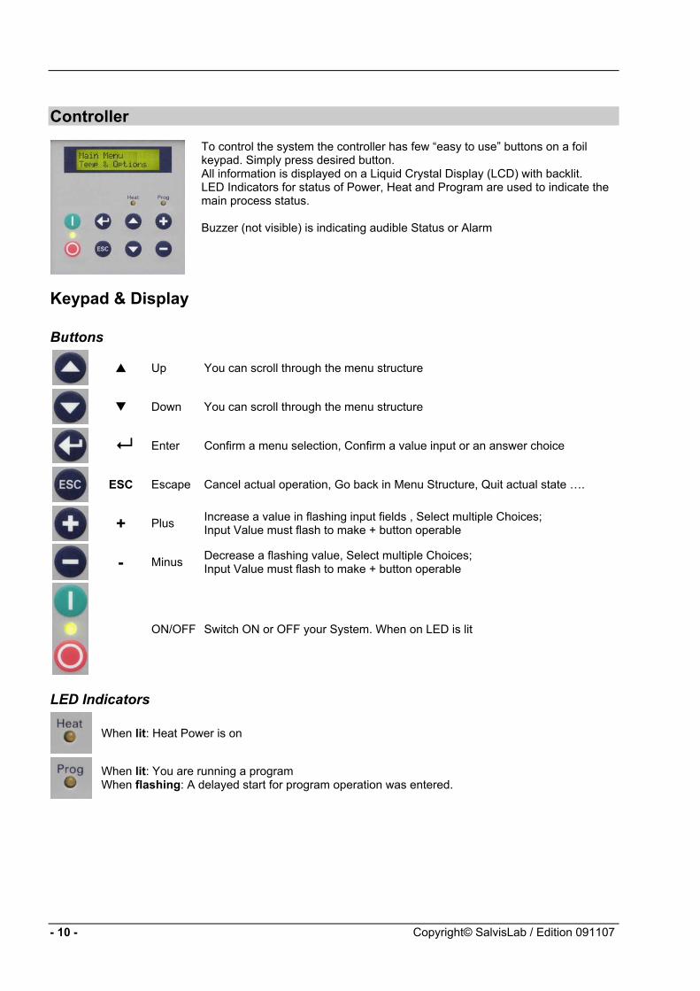
To control the system the controller has few “easy to use” buttons on a foil keypad. Simply press desired button. All information is displayed on a Liquid Crystal Display (LCD) with backlit. LED Indicators for status of Power, Heat and Program are used to indicate the main process status. Buzzer (not visible) is indicating audible Status or Alarm
Keypad & Display
Buttons
Up You can scroll through the menu structure
Down You can scroll through the menu structure
Enter Confirm a menu selection, Confirm a value input or an answer choice
ESC Escape Cancel actual operation, Go back in Menu Structure, Quit actual state ….
+ Plus Increase a value in flashing input fields , Select multiple Choices;
Input Value must flash to make + button operable
- Minus Decrease a flashing value, Select multiple Choices;
Input Value must flash to make + button operable
ON/OFF Switch ON or OFF your System. When on LED is lit
LED Indicators
When lit: Heat Power is on
When lit: You are running a program When flashing: A delayed start for program operation was entered.
- 10 - Copyright© SalvisLab / Edition 091107

Operating
How to interpret displays described in this manual...
Power ON Sequence
Salvis Lab Revision XX.XX
By pressing the power-on button, the display will show the software version. All standard, pre-setted or saved information will be loaded during this process. After a while display will show first Main Menu Point
Input Field
Set Temperature 180.0°C
A input value which is underlayed with yellow(grey) background means this value is flashing on the real display.
Multiple Input Fields
Set_Start-Date__ DDMMYY__17.08.08
If you reach a multiple input display first time, the first part (… of 3 in this example) of the input field is flashing to indicate input here.. Flashing input fields are changed with +/- keys
Multiple Choice Fields
Display_Interval Off___On_______
In a multiple choice field the last actual setted (pre-set) option will flash. Change option with + or – and confirm with
Definitions of terms
What is a Set Temperature? A Set Temperature is the target temperature you want operate the system with.
What is a Gradient? A Gradient is the slope of the heating up process to the specific set temperature. It is indicated as ºC / Minute. Negative Gradients are not allowed. The maximal value of a gradient is system depending and has a range and is pre-defined by factory. A system specific curve of gradient corridors see
What is a Fan Speed? The Fan-Speed is a percentage of a range of rounds per minute. The minimal or maximal RPM Value is system depending. The % Value is based on this min/max range.
What is a Holding Time? A timer is used to specify how long a set temperature has to be hold. The timer starts counting back when the set temperature is reached. The maximal time you can set is: 999 hours and 59 minutes. This equals a max time of 41 days 15 hours and 59 minutes
What is a Start Date/Time If you are using a start date or time you will be able to set a future date/time to start the system with pre-setted parameters i.e. temperature, Gradient, Fan Speed, Timer
Copyright© SalvisLab / Edition 091107 - 11 -

Main Menu Overview General operation buttons
In general you can scroll through the menu points with the or button. Select the desired menu point with
1 Temperature & Options
Main Menu Temp & Options
Manual operation with a set temperature. You can select options like gradient, hold-time (dwell-time), fan speed, pre-setted start date/time. Press to select 1.1 ESC returns to 1
2 Program
Main Menu Program
The menu Program is divided in menus for creating, editing, deleting and printing programs. Press to select 2.1 ESC returns to 1
3 Configuration
Main Menu Configuration
This menu point allows you to configure the system Press to select 3.1 ESC returns to 1
4 Service Mode
Main Menu Service Mode
This menu point is protected by an access-code and is available only for trained Service-Technicians. Press to select 4.1 ESC returns to 1
- 12 - Copyright© SalvisLab / Edition 091107

1 Main Menu Temp & Options
Main Menu Temp & Options
Manual operation with a set temperature. You can select options like gradient, hold-time (dwell-time), fan speed, pre-setted start date/time. Press to select 1.1 ESC returns to 1
1.1 Set Temperature
Set_Temperature__________120.0°C
+/- change desired value. confirms and saves value 1.2
ESC restores the old value or returns to 1
1.2 Select Quick Start or Start with Options
Start_?___ Now__ Options___
+/- Select desired answer confirms and saves value
If Now selected: System will start immediately 6 If Option selected 1.3 ESC cancels and returns to 1
1.3 Set Gradient
Gradient 2,0°C/Min
+/- Change value confirms and saves the value 1.4
ESC restores the old value or returns to 1 Note: A value of 0,0 means maximal possible gradient value!
1.4 Set Holding Time (dwell time)
Hold Time_______HHH:MM____105:00
+/- Change value confirm value and skips to the next input field (HH MM) or
stores the time and go to 1.5 ESC restores the old value and skips back one input field (MM HH) or goes back to 1 Note: A value of 0:00 means endless holding time
1.5 Set Fan Speed
Fan_Speed ____________100%
+/- Change value confirms and saves the value 1.6
ESC restores the old value or returns to 1 Note: The minimal Fan Speed is depending on the system and is factory set.
Copyright© SalvisLab / Edition 091107 - 13 -

1.6 Set Start-Date
Start Date DDMMYY__15.05.02
+/- Change desired value confirm value and skips to the next input field (DD MM,
MM YY) or stores the date and go to 1.7 ESC restores the old value and skips back one input field (YY MM, MM DD) or goes back to 1 Note: The pre-set date is the actual date from the real-time clock.
1.7 Set Start Time
Start Time__ HH:MM______13:10
+/- Change desired value confirm value and skips to the next input field (HH MM) or
stores the time and go to : If the Start Date and/or Start Time is in the past, the display will return back to 1 If your Start Date and/or Start Time is in the future you will see the operating display 5 ESC restores the old value and skips back one input field (MM HH) or goes back to 2.1 Note: The pre-set time is the actual time from the real-time clock.
- 14 - Copyright© SalvisLab / Edition 091107

2 Main Menu Program
Main_Menu _Program
The menu Program is divided in menus for creating, editing, deleting and printing programs. Press to select 2.1
/ to scroll through the Main Menu ESC return to 1
2.1 Menu Program - Start
Menu_Program_____Start
Start an existing program confirm menu choice 2.1.1 / scroll through the Menu.
ESC return to 2
2.2 Menu Program - New
Menu_Program_____New
Create a new program confirm menu choice 2.2.1 / scroll through the Menu.
ESC return to 2
2.3 Menu Program - Edit
Menu_Program_____Edit
Edit an existing program confirm menu choice 2.3.1 / scroll through the Menu.
ESC return to 2
2.4 Menu Program - Delete
Menu_Program_____Delete
Delete an existing program to select [Delete Program] 2.4.1 / scroll through the Menu.
ESC return to 2
2.5 Menu Program - Print
Menu_Program_____Print
Print a program to select [Print Program] 2.5.1 / to scroll through the Menu.
ESC return to 2
Copyright© SalvisLab / Edition 091107 - 15 -

2.1 Menu Program Start
Menu_Program____ _Start
Start an existing program confirm menu choice 2.1.1 / scroll through the sub-menu.
ESC returns to 2
2.1.1 Select Program #
Program # ? P04
+/- select desired program number confirm value 2.1.2
ESC returns to 2.1 Note: Only stored only program numbers with content will appear in the display. If no program exist a beep-message will displayed.
2.1.2 Choose type of program start
Start_Prog___P04 Now_Delayed
+/- select type of program start accept choice
If Now selected: System starts immediately 6 If Delayed selected : 2.1.3 ESC returns to 2.1
2.1.3 Set Start Date
Start Date___P04 DDMMYY__15.05.02
+/- Change desired value confirm value and skips to the next input field (DD MM,
MM YY) or stores the date and go to 2.1.4 ESC restores the old value and skips back one input field (YY MM, MM DD) or goes back to 2.1 Note: The pre-set date is the actual date from the real-time clock.
2.1.4 Set Start Time
Start Time___P04 HH:MM______13:10
+/- Change desired value confirm value and skips to the next input field (HH MM) or
stores the time and go to : If the Start Date and/or Start Time is in the past, the display will return back to 2.1.2 If your Start Date and/or Start Time is in the future you will see the operating display 7 ESC restores the old value and skips back one input field (MM HH) or goes back to 2.1 Note: The pre-set time is the actual time from the real-time clock.
- 16 - Copyright© SalvisLab / Edition 091107
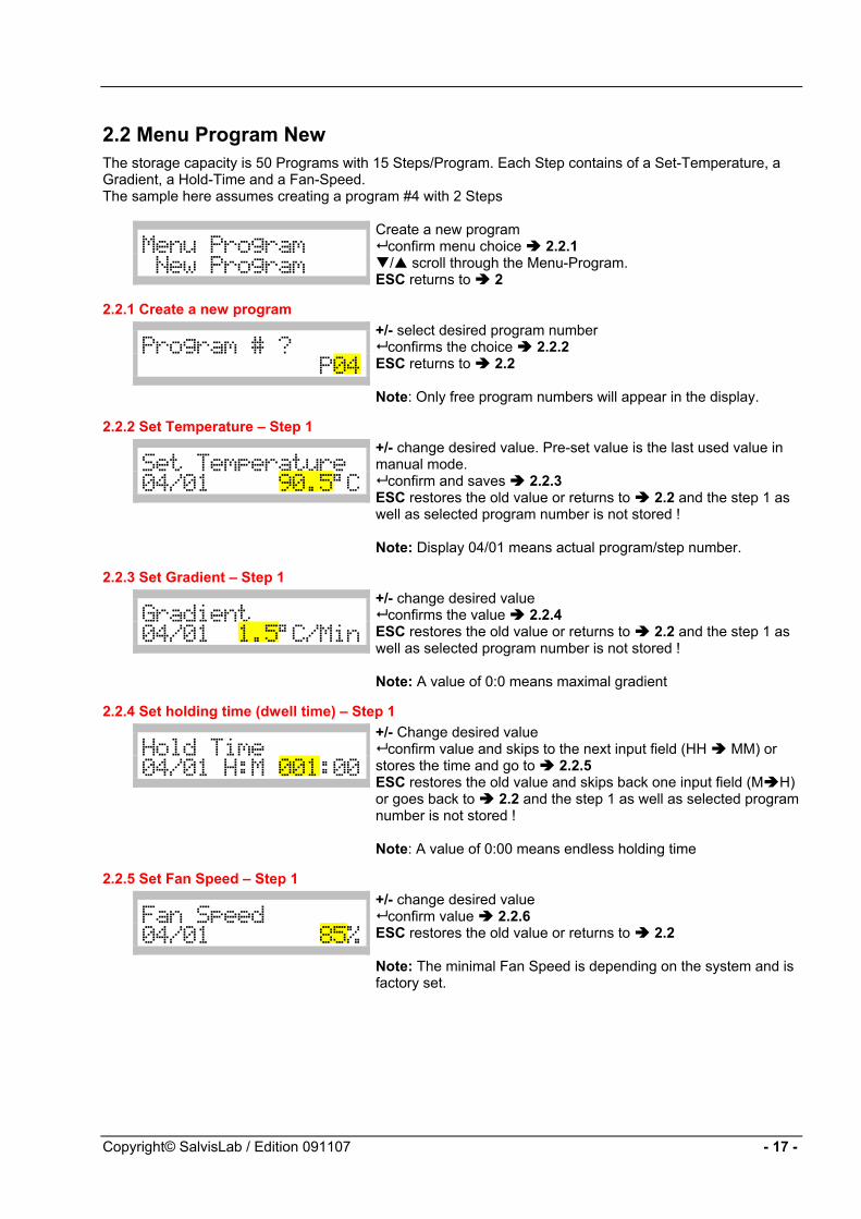
2.2 Menu Program New The storage capacity is 50 Programs with 15 Steps/Program. Each Step contains of a Set-Temperature, a Gradient, a Hold-Time and a Fan-Speed. The sample here assumes creating a program #4 with 2 Steps
Menu_Program_____New_Program__
Create a new program confirm menu choice 2.2.1 / scroll through the Menu-Program.
ESC returns to 2
2.2.1 Create a new program
Program # ?__ _____________P04
+/- select desired program number confirms the choice 2.2.2
ESC returns to 2.2 Note: Only free program numbers will appear in the display.
2.2.2 Set Temperature – Step 1
Set_Temperature_04/01_____90.5°C
+/- change desired value. Pre-set value is the last used value in manual mode.
confirm and saves 2.2.3 ESC restores the old value or returns to 2.2 and the step 1 as well as selected program number is not stored ! Note: Display 04/01 means actual program/step number.
2.2.3 Set Gradient – Step 1
Gradient 04/01__1.5°C/Min
+/- change desired value confirms the value 2.2.4
ESC restores the old value or returns to 2.2 and the step 1 as well as selected program number is not stored ! Note: A value of 0:0 means maximal gradient
2.2.4 Set holding time (dwell time) – Step 1
Hold_Time 04/01_H:M_001:00
+/- Change desired value confirm value and skips to the next input field (HH MM) or
stores the time and go to 2.2.5 ESC restores the old value and skips back one input field (M H) or goes back to 2.2 and the step 1 as well as selected program number is not stored ! Note: A value of 0:00 means endless holding time
2.2.5 Set Fan Speed – Step 1
Fan_Speed 04/01________85%
+/- change desired value confirm value 2.2.6
ESC restores the old value or returns to 2.2 Note: The minimal Fan Speed is depending on the system and is factory set.
Copyright© SalvisLab / Edition 091107 - 17 -

2.2.6 Choose if a additional step is required
New_Step_?______ Yes No
+/- Select desired answer accept
If Yes selected: step number will increment with 1 2.2.7 If No selected: 2.2.12
2.2.7 Set Temperature – Step 2
Set_Temperature_ 04/02____110.0°C
+/- change desired value confirm the value 2.2.8
ESC restores the old value or if in step 2 and higher returns to 2.2.6 but the actual step will not be saved !
Note: Display 04/02 means actual program/step number
2.2.8 Set Gradient – Step 2
Gradient 04/02 2.0°C/Min
+/- change desired value confirm the value 2.2.9
ESC restores the old value or if in step 2 and higher returns to 2.2.6 but the actual step will not be saved !
2.2.9 Set Holding Time – Step 2
Hold_Time___ 04/02_H:M_001:30
+/- Change desired value confirm value and skips to the next input field (HH MM) or
stores the time and go to 2.2.10 ESC restores the old value and skips back one input field (M H) or if in step 2 and higher returns to 2.2.6 but the actual step will not be saved ! Note: A value of 0:00 means endless holding time
2.2.10 Set Fan Speed - Step 2
Fan_Speed 04/02______ 100%
+/- change desired value confirm the value 2.2.11
ESC restores the old value or if in step 2 and higher returns to 2.2.6 but the actual step will not be saved !
- 18 - Copyright© SalvisLab / Edition 091107

2.2.11 Choose if a additional step is required
New_Step_?______Yes No
+/- Select desired answer accept
If Yes selected: step number will increment with 1 2.2.7 If No selected: 2.2.12
2.2.12 End of programming sequence
End_of_Program_?Yes No
+/- Select desired answer accept
If Yes selected: 2.2.13 If No selected: 2.2.11
2.2.13 Confirming & Saving the new program
Program______P04Stored..._______
Displays confirmation that the new program has been stored. After a few seconds the display will return to 2.2
Copyright© SalvisLab / Edition 091107 - 19 -
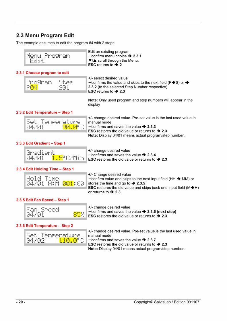
2.3 Menu Program Edit The example assumes to edit the program #4 with 2 steps
Menu_Program____ _Edit
Edit an existing program confirm menu choice 2.3.1 / scroll through the Menu.
ESC returns to 2
2.3.1 Choose program to edit
Program Step P04 S01
+/- select desired value confirms the value and skips to the next field (P S) or
2.3.2 (to the selected Step Number respective) ESC returns to 2.3 Note: Only used program and step numbers will appear in the display
2.3.2 Edit Temperature – Step 1
Set_Temperature_ 04/01_____90.0°C
+/- change desired value. Pre-set value is the last used value in manual mode.
confirms and saves the value 2.3.3 ESC restores the old value or returns to 2.3 Note: Display 04/01 means actual program/step number.
2.3.3 Edit Gradient – Step 1
Gradient____ 04/01__1.5°C/Min
+/- change desired value confirms and saves the value 2.3.4
ESC restores the old value or returns to 2.3
2.3.4 Edit Holding Time – Step 1
Hold_Time___ 04/01_H:M_001:00
+/- Change desired value confirm value and skips to the next input field (HH MM) or
stores the time and go to 2.3.5 ESC restores the old value and skips back one input field (M H) or returns to 2.3
2.3.5 Edit Fan Speed – Step 1
Fan_Speed___ 04/01________85%
+/- change desired value confirms and saves the value 2.3.6 (next step)
ESC restores the old value or returns to 2.3
2.3.6 Edit Temperature – Step 2
Set_Temperature_ 04/02____110.0°C
+/- change desired value. Pre-set value is the last used value in manual mode.
confirms and saves the value 2.3.7 ESC restores the old value or returns to 2.3 Note: Display 04/01 means actual program/step number.
- 20 - Copyright© SalvisLab / Edition 091107

2.3.7 Edit Gradient – Step 2
Gradient____ 04/02__1.2°C/Min
+/- change desired value confirms and saves the value 2.3.8
ESC restores the old value or returns to 2.3
2.3.8 Edit Holding Time – Step 2
Hold_Time___ 04/01_H:M_000:58
+/- Change desired value confirm value and skips to the next input field (HH MM) or
stores the time and go to 2.3.9 ESC restores the old value and skips back one input field (M H) or returns to 2.3
2.3.9 Edit Fan Speed – Step 2
Fan_Speed___ 04/02_______100%
+/- change desired value confirms and saves the value 2.3.10 (next step)
ESC restores the old value or returns to 2.3
2.3.10 Decide if a new step must be added
New_Step_?______Yes__No
+/- Select desired answer accept
If Yes selected: step number will increment with 1 2.3.6 If No selected: 2.3.11
2.3.11 Confirm end of editing program
End_of_Program_?Yes__No
+/- Select desired answer accept
If Yes selected: 2.3.12 If No selected: 2.3.10
2.3.12 Save program display
Program______P04Stored..._______
Displays confirmation that the new program has been stored. After a few seconds the display will return to 2.3
Copyright© SalvisLab / Edition 091107 - 21 -

2.4 Menu Program Delete
Menu_Program____ _Delete_
Delete an existing program select menu 2.4.1 / scroll through the menu.
ESC returns to 2.4
2.4.1 Choose program # to be deleted
Program # ?__ _____________P04
+/- select desired program number accept 2.3.2
ESC returns to 2.4 Note: Only used program numbers will appear in the display
2.4.2 Deletion confirmation will be displayed
Delete_Program__ Yes__No
+/- Select desired answer accept
If Yes selected: 2.4.3 If No selected: 2.4
2.4.3 Deletion confirmation will be displayed
Program______P04 Deleted..._____
Display confirms that the selected program has been deleted. After a few seconds it will go to 2.4
If you delete a program means you delete all steps associated to this program number. After deleting, the number is now available in the list of free program numbers.
2.5 Menu Program Print
Menu_Program____ _Print
Print a program to select [Print Program] 2.5.1 / to scroll through the Menu.
ESC return to 2
2.5.1 Choose program # to be printed
Program # ?__ _____________P04
+/- select desired program number accept 2.5.2
ESC return to 2 Note: Only used program numbers will appear in the display
2.5.2 Displaying print in progress
Program______P04 Printing..._ __
Display confirms that the program has been printed. After a few seconds it will return to 2.5
For an example of printout and printer connection refer section Printer Operation
- 22 - Copyright© SalvisLab / Edition 091107

3 Main Menu Configuration Configuration of the system by the user
Main_Menu________Configuration__
In this menu point you can define and set system options Press to select 3.1
/ scroll through the menu.
3.1 Select language
Language________EN_GE_FR_IT_ES
+/- Select the desired language confirm selection 3.2
Attention: After confirmation the selection all subsequent dialogs are displayed in the selected language.
3.2 Set actual date for internal real-time clock (this is a sample)
Actual_Date_____DDMMYY__09.06.04
+/- change value accept value and skips to the next input field ((DD MM,
MM YY) or saves the date and goes to 3.3 ESC restores the old value and/or skips back one input-field (YY MM, MM DD)
3.3 Set actual time for internal real-time clock (this is a sample)
Actual_Time_____HH:MM 23:59
+/- change value accept value and skips to the next input field ((HH MM) or
saves the time and goes to 3.4 ESC restores the old value and/or skips back one input-field (MM HH)
3.4 Set allowed max Temperature
Max.Temperature__________300.0°C
Set the maximal possible temperature value for manual operation.+/- change value
accept value 3.5 ESC restores value
3.5 Set print interval for printer log via serial RS232 Interface
Print_Interval__HHMM_______00:01
Set the Print Interval time. A value of 00:00 will disable printout of operating values. +/- change value
accept value and skips to the next input field ((HH MM) or saves the time and goes to 3.4 ESC restores the old value and/or skips back one input-field (MM HH)
Copyright© SalvisLab / Edition 091107 - 23 -

3.6 Set automatic interval to scroll status displays
Display_Interval Yes No
Select if operation displays will switch automatically instead of manually switching by / keys +/- toggle answer
accept 3.7
3.7 Select Baud Rate for serial RS232 Interface
RS232_Baud_Rate ___________1200
Available Baud Rate are1200/2400/4800/9600. +/- select value
accept 3.8
3.8 Set Program End Buzzer
Buzzer_Prog_End Yes No_____
Buzzer sends a signal if a program has finished signal. +/- toggle option
accept 3.9
3.9 Set Safety Alarm-Buzzer
Buzzer_SafetyBon Yes No _____
In any case of an over temperature alarm situation, the Buzzer will give an audio signal. +/- toggle option
accept 3.10
3.10 Set LCD Display contrast
Display Contrast 75%
+/- change value accept 3.11
ESC restores value
3.11 Set Offset between internal PT100 Sensor and actual display
Sensor Offset 0,0°C
Offsets the internal PT100 sensor with the actual displayed temperature. Calibrate with an external temperature sensor. +/- change value
accept 3.12 ESC restores value
3.12 Confirmation display of storing entered values
Configuration Stored...
The Display confirms that the Configuration has been Stored. After a few seconds it will return to 3
4 Menu Service Mode
Main_Menu _Service_Mode
This menu point is protected by a code and is only available for trained Service-Technicians.
- 24 - Copyright© SalvisLab / Edition 091107

Operating Displays
General Change the display with / keys or set Display Interval to yes in Menu Configuration to let change the display automatically every 10 sec.
5 Operating Display: Manual Mode Delayed Start
Start-Date 09.09.04 13:10
Here you can see the actual Start Date and Time. Press to get next set of operating displays.
SetTemp 120.0°C Holdtime 105:00
Here you can see the Set Temp and the Hold Time (dwell time). Press to get next set of operating displays.
Fan 100% Gradient 2,0°C/M
Here you can see the Fan-Speed and gradient Press to get next set of operating displays.
6 Status Display: Normal Mode Running
Set Temp 120.0°CAct Temp 35.5°C
Here you can see the Set Temp and the Actual Temp. Press to get more information’s of the Operating Display.
Fan Speed 100%Timer 105:00
Here you can see the Fan Speed and the Timer. Press to get more information of the Operating Display.
Date 05.05.04Time 14:18
Here you can see the actual Date and Time. This is the last information of the Operating Display. Press the button to see first display again
Copyright© SalvisLab / Edition 091107 - 25 -

7 Status Display: Program mode Delayed Program Start If the programmed Start Date/Time has archieved the Display switches to 8
The „Prog“ LED is on during a programmed operation
Start Date P04 09.09.04 13:10
Here you can see the actual Start Date and Time. Press to get more information of the Operating Display.
8 Status Display: Program mode Program Running
Set Temp 90.0°C Act Temp 35.5°C
Here you can see the Set Temperature and the Actual Temperature of the Program Step. Press to get more information of the Operating Display.
Program 04 Step 01
Here you can see the Program Number and the Step. Press the button to get more information of the Operating Display.
Fan 100% Gradient 2,0°C/M
Here you can see the Fan Speed and the Gradient. Press the button to get more information of the Operating Display.
Hold Time 120:30 09.09.04 14:09
Here you can see the Hold Time and actual Date and Time in the format DD.MM.YY. This is the last information of the Operating Display. Press the button to see first display again
If the programm has ended a beep tone (5x) will sound and following display will shown:
Status: Program finished
Status Message can be confirmed by pressing the key.
9 Cancel a running process by ESC Key A running system is stopped by pressing ESC.
9.1 Safety question when stopping a running system
Stop Process? Yes No
+/- Select desired answer accept
If Yes selected: 9.2 If No selected: Back to running status
9.2 Conformation of canceling a process
Process stopped
Display confirms that the running process has been canceled. After a few seconds it will return to Main Menu 1
- 26 - Copyright© SalvisLab / Edition 091107

10 Messages and Errors The messages and Errors are announced with a beep tone (5x) and can be confirmed by pressing the Key. Errors are severe system failures and must fixed by trained service people.
Messages
Message: No Program
Indicates that no program is in memory
Message: Memory Full
Indicates that the program memory is full
Message: Door Open
Indicates that the door is open while you try to start the system (TC40,TC100 only)
Errors
Error: PT100
PT100 Sensor or cable defect. Call Service
Error: Safety Bond
Safety Controller was active. Call Service
Error: Tmp out of range
Temperature exceeded security range level. Cool down oven. If error persist call Service
Unexpected Error
Call Service
Copyright© SalvisLab / Edition 091107 - 27 -
Printer Operation
Connecting a Printer
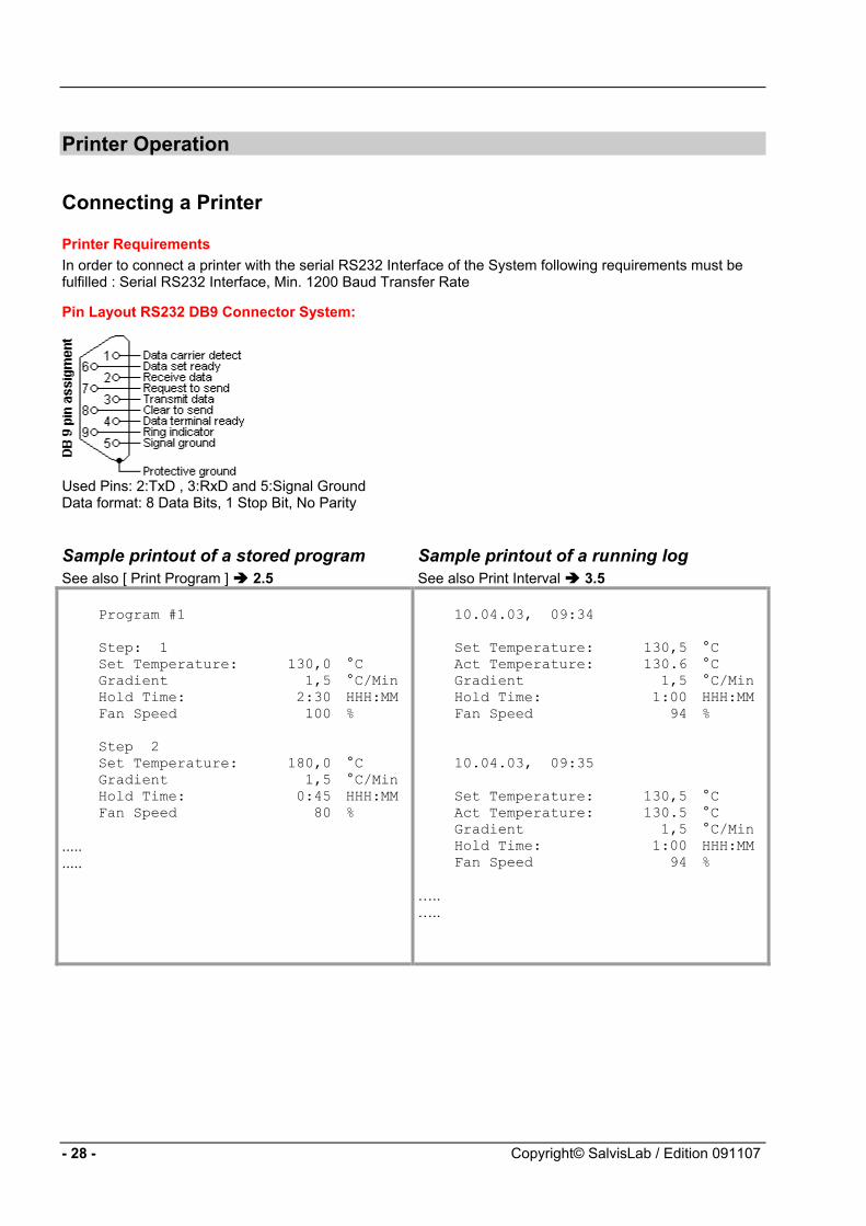
Printer Requirements In order to connect a printer with the serial RS232 Interface of the System following requirements must be fulfilled : Serial RS232 Interface, Min. 1200 Baud Transfer Rate
Pin Layout RS232 DB9 Connector System:
Used Pins: 2:TxD , 3:RxD and 5:Signal Ground Data format: 8 Data Bits, 1 Stop Bit, No Parity
Sample printout of a stored program See also [ Print Program ] 2.5
Sample printout of a running log See also Print Interval 3.5
Program #1 Step: 1 Set Temperature: 130,0 °C Gradient 1,5 °C/Min Hold Time: 2:30 HHH:MM Fan Speed 100 % Step 2 Set Temperature: 180,0 °C Gradient 1,5 °C/Min Hold Time: 0:45 HHH:MM Fan Speed 80 %
..... .....
10.04.03, 09:34 Set Temperature: 130,5 °C Act Temperature: 130.6 °C Gradient 1,5 °C/Min Hold Time: 1:00 HHH:MM Fan Speed 94 % 10.04.03, 09:35 Set Temperature: 130,5 °C Act Temperature: 130.5 °C Gradient 1,5 °C/Min Hold Time: 1:00 HHH:MM Fan Speed 94 %
….. …..
- 28 - Copyright© SalvisLab / Edition 091107
Appendix A
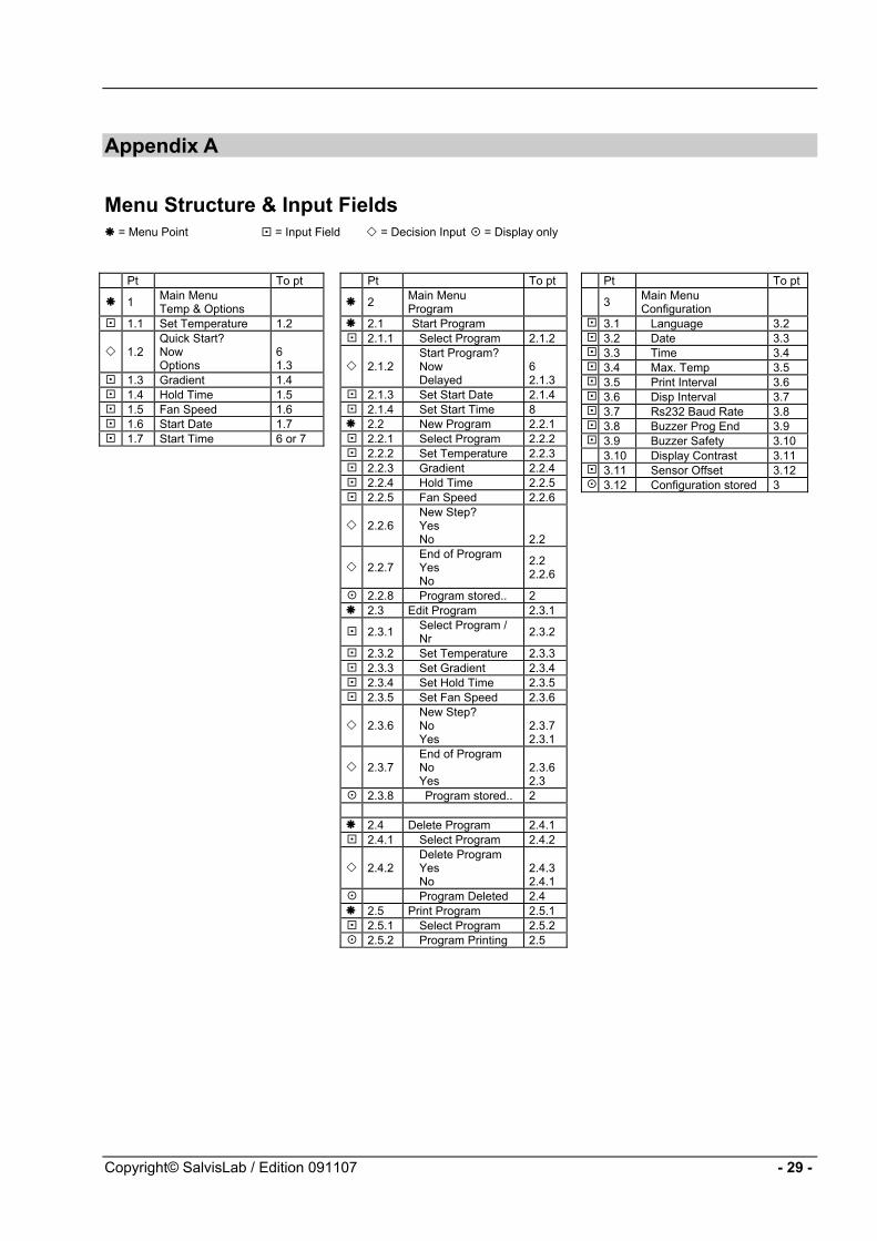
Menu Structure & Input Fields = Menu Point = Input Field = Decision Input = Display only
Pt To pt
1 Main Menu Temp & Options
1.1 Set Temperature 1.2
1.2 Quick Start? Now Options
6 1.3
1.3 Gradient 1.4 1.4 Hold Time 1.5 1.5 Fan Speed 1.6 1.6 Start Date 1.7 1.7 Start Time 6 or 7
Pt To pt
2 Main Menu Program
2.1 Start Program 2.1.1 Select Program 2.1.2
2.1.2 Start Program? Now Delayed
6 2.1.3
2.1.3 Set Start Date 2.1.4 2.1.4 Set Start Time 8 2.2 New Program 2.2.1 2.2.1 Select Program 2.2.2 2.2.2 Set Temperature 2.2.3 2.2.3 Gradient 2.2.4 2.2.4 Hold Time 2.2.5 2.2.5 Fan Speed 2.2.6
2.2.6 New Step? Yes No
2.2
2.2.7 End of Program Yes No
2.2 2.2.6
2.2.8 Program stored.. 2 2.3 Edit Program 2.3.1
2.3.1 Select Program / Nr 2.3.2
2.3.2 Set Temperature 2.3.3 2.3.3 Set Gradient 2.3.4 2.3.4 Set Hold Time 2.3.5 2.3.5 Set Fan Speed 2.3.6
2.3.6 New Step? No Yes
2.3.7 2.3.1
2.3.7 End of Program No Yes
2.3.6 2.3
2.3.8 Program stored.. 2
2.4 Delete Program 2.4.1 2.4.1 Select Program 2.4.2
2.4.2 Delete Program Yes No
2.4.3 2.4.1
Program Deleted 2.4 2.5 Print Program 2.5.1 2.5.1 Select Program 2.5.2 2.5.2 Program Printing 2.5
Pt To pt
3 Main Menu Configuration
3.1 Language 3.2 3.2 Date 3.3 3.3 Time 3.4 3.4 Max. Temp 3.5 3.5 Print Interval 3.6 3.6 Disp Interval 3.7 3.7 Rs232 Baud Rate 3.8 3.8 Buzzer Prog End 3.9 3.9 Buzzer Safety 3.10
3.10 Display Contrast 3.11 3.11 Sensor Offset 3.12 3.12 Configuration stored 3
Copyright© SalvisLab / Edition 091107 - 29 -

Appendix B
Wiring diagramm A1 = Regelplatine / PCB board
-
PN E
X6
X9
X7
X5X2
F4
X3
C7
C5
C2
U5
(EE
PRO
M)
1
2
3
4
5
14
R
9
13
P
N
X1 F1
E1 M1
R R W
A1
A2
X13X12
X8
X11
A2 = Display Platine / Display boardE1 = Heizung / Heating element
F1 = Hauptsicherung / Main fuseF2 = Uebertemp. Thermostat / Overtemp. ThermostatF4 = Sicherung Regelplatine / PCB fuse
X1 = Netzanschlussklemme/ Main power clampX2 = Netzanschluss Regelplatine/ Main power PCBX3 = Anschluss RS232 PCB / Connector RS232 PCB
X5 = Anschluss Pt100 / Connector Pt100X6 = Leer / EmptyX7 = Anschluss Türendschalter / Connector door switchX8 = Anschluss Heizung / Connector heating elementX9 = Anschluss Ventilator / Connector Ventilator
X12 = Leer / EmptyX13 = Anschluss Display / Connector Display
X10 = Anschluss Heizung 115V >1000W
Elek
tro-S
chem
a TC
160/
240/
400
Elec
trica
l dia
gram
m T
C16
0/24
0/40
0
X10
X11 = Speisung Heizung / Connector heating element Connector Heating 115V >1000W
X4 = Anschluss RS232 Ext. / Connector RS232 Ext.
X4
F2
10
15
12
E2 M2
E2 = Heizung / Heating element
M2 = Ventilator / FanM1 = Ventilator / Fan
SW
R
W
BL
11 7
16
8
MADE BY RENGGLI
30 - Copyright© SalvisLab / Edition 091107

Appendix C
Drawing Thermocenter TC 160
800 680
720
535
580
475
- 31 - Copyright© SalvisLab / Edition 191107
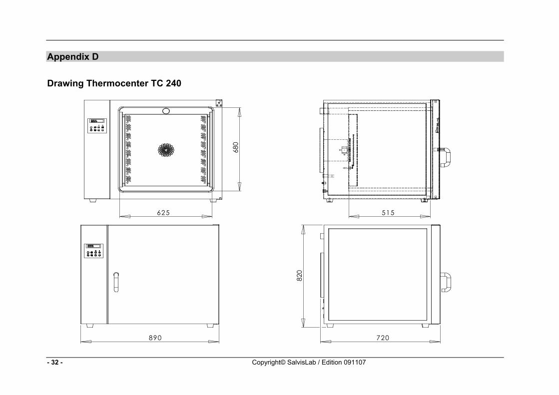
Appendix D
Drawing Thermocenter TC 240
890 720
820
625
680
515
- 32 - Copyright© SalvisLab / Edition 091107
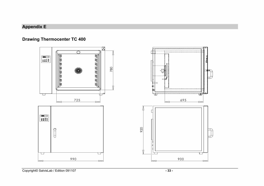
Appendix E
Drawing Thermocenter TC 400
780
725
990
920
900
695
Copyright© SalvisLab / Edition 091107 - 33 -
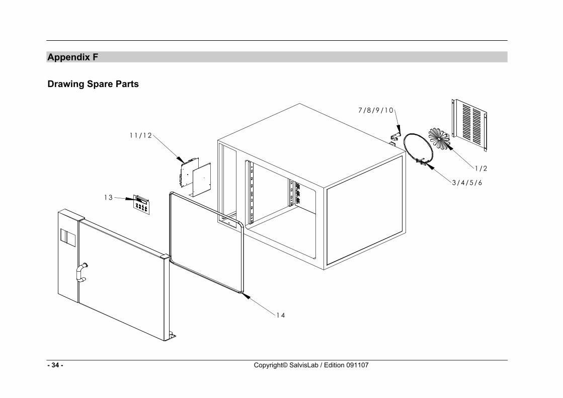
Appendix F
Drawing Spare Parts
1 /2
3 /4 /5 /6
7 /8 /9 /1 0
11 /12
13
14
- 34 - Copyright© SalvisLab / Edition 091107
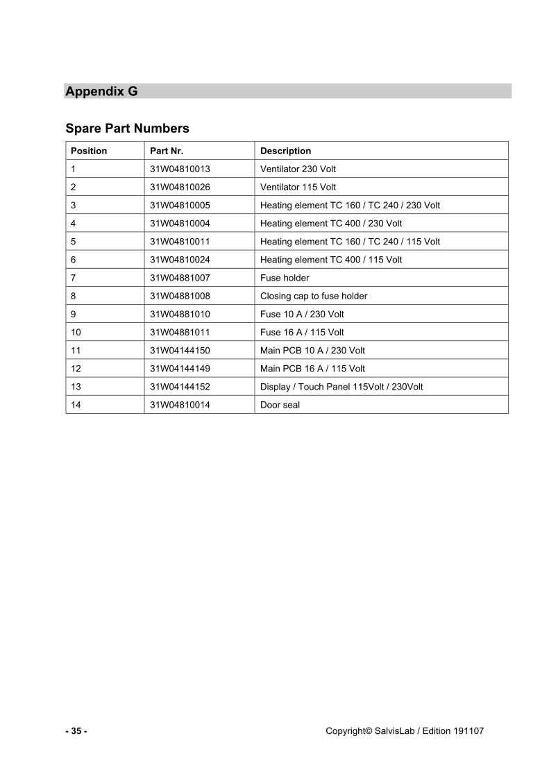
Appendix G
Spare Part Numbers Position Part Nr. Description
1 31W04810013 Ventilator 230 Volt
2 31W04810026 Ventilator 115 Volt
3 31W04810005 Heating element TC 160 / TC 240 / 230 Volt
4 31W04810004 Heating element TC 400 / 230 Volt
5 31W04810011 Heating element TC 160 / TC 240 / 115 Volt
6 31W04810024 Heating element TC 400 / 115 Volt
7 31W04881007 Fuse holder
8 31W04881008 Closing cap to fuse holder
9 31W04881010 Fuse 10 A / 230 Volt
10 31W04881011 Fuse 16 A / 115 Volt
11 31W04144150 Main PCB 10 A / 230 Volt
12 31W04144149 Main PCB 16 A / 115 Volt
13 31W04144152 Display / Touch Panel 115Volt / 230Volt
14 31W04810014 Door seal
- 35 - Copyright© SalvisLab / Edition 191107