thermomax - thermo technologies - solar water heaters, …thermomax.com/downloads/thermomax...
TRANSCRIPT

thermomax�
Evacuated Solar Energy Collector
Technical Reference & Installation Manual
Thermo Technologies5560 Sterrett PlaceSuite 115 Columbia, MD 21044Tel.: (410) 997-0779 www.thermomax.com Fax.: (410) 997-0778 [email protected]
Contents
CONTENTS
1.0 What does THERMOMAX offer 1
2.0 How to get the most out of a THERMOMAX system 2
3.0 How does a THERMOMAX system work 3 3.1 The THERMOMAX Tube 3.1.1 The Absorber 3.1.2 The Evacuated Glass Tube 4 3.1.3 The Condenser 3.2 The THERMOMAX MS Manifold 3.3 Accessories 5 3.3.1 Roof fixing kits 6 3.3.2 Solar Differential Controller
4. How does a THERMOMAX system perform 8 4.1 Solar Fundamentals 4.2 Thermal Performance
5.0 How to design a THERMOMAX system 10 5.1 Collector Area 5.2 Flow rate 5.3 Pipework 11 5.4 Circulation Pump 5.5 Expansion Vessel 13 5.6 Hydraulics 14 5.6.1 Collector System 5.6.2 Overall System Design
6.0 How to install a THERMOMAX system 19 6.1 General 6.2 Manifold Connections 6.3 MS-System 21 6.4 KS-System 24 6.5 FS-System 27 6.6 Alternative Methods 30 6.7 Commissioning
7.0 How to maintain a THERMOMAX System 31 7.1 Periodic Checks 7.2 Optional Checks 7.3 Five Yearly Checks
8.0 Trouble Shooting 32
i
Contents
9.0 Appendix 33 9.1 Products and Spare Parts 9.2 System sizing tables 35 9.3 Solar Radiation Table 37 9.4 Checklist 38/39 9.5 Calculation Sheet 38/40 9.6 Commissioning Sheet 38/42
ii
About THERMOMAX
(1.0) What does THERMOMAX offer
Solar Division
Thermomax Ltd. is a leading manufac-turer of high efficiency equipment for effi-cient and economical conversion of solar radiation into thermal energy. Based in two locations in the United Kingdom, and a unit in Italy, Thermomax occupies over 10,000m² of purpose built factories on 10 acres (40,400m²) of land. The operation is complete with engineering and administra-tion offices, manufacturing plants, devel-opment laboratory and testing facilities. Thermomax has a staff of professional, technical and production personnel with a high degree of dedication and compe-tence. The evacuated heat-pipe solar collector is the result of extensive research, devel-opment and testing. These high perform-ance, reliable and cost effective solar modules use advanced technology and new materials. Thermomax’s manufacturing operations are geared to volume production and high quality assurance. The plants are well equipped with modern machinery and specialised tooling for efficient and reliable production. Thermomax’s engineering fac-tory in northern Italy is involved in manu-facturing some of the unique and sophisti-cated equipment needed for production purposes as well as specialised compo-nents. Electronic Division
An electronic div ision, established in 1990, produces microprocessor controllers for the solar heating systems as well as sophisticated controllers and data loggers for commercial refrigeration applications. The Market
The market for Thermomax solar prod-ucts is worldwide and is managed through a network of distributors, dealers and in-dependent agents. These firms provide
application and installation assistance to users, architects, engineers and contrac-tors. Thermomax is currently sold to over 40 countries with Western Europe, Far East and the United States as its main markets. The number of Thermomax collector tubes in service throughout the world is now in the millions. Satisfied Thermomax users achieve considerable savings in their fuel cost as well as contributing towards a re-duction in CO2 emissions. Installations in extreme climates such as Africa and the Antarctic clearly show the exceptional design characteristics of the Thermomax systems. Thermomax solar collectors are used to produce clean energy for domestic and industrial hot water, space heating and cooling. Projects such as the solar water heating at Singapore Airport are the larg-est of their k ind, confirming international acknowledgement and full confidence in the Company and its products. Assured and approved Quality
Thermomax solar manufacturing plants are fully registered to the internationally recognised ISO Quality Management Sys-tems; the Company has obtained ISO 9001 certificate. Thermomax collectors are tested and certified by major independent testing au-thorities in Germany, Switzerland, United States, Great Britain and Australia. Ther-momax has received 10 major awards, the first being a 1982 Technology Award re-ceived in Germany and two prestige Queen’s Awards for export achievement. The Design Council confirms the Thermo-max collector to be an outstand ng Br t-ish Product and winner of a “Millennium Award”. Thermomax products and produc-tion techniques are protected throughout the world by several pat-ents.
i i
1
Cautions
(2.0) How to get the most out of a THERMOMAX� system
We recommend you to read this man-ual thoroughly before commencing instal-lation and to adhere to the cautions given and to all local authorities regulations and relevant standards. 1. Thermomax� systems should only be
installed by qualified persons. If in doubt about any aspect of the instal-lation contact your Thermomax dealer.
�
2. System sizing and application must be in accordance with recommendations by Thermomax�.
3. Responsibility for safe and proper installation of a Thermomax� solar water heating system rests with the installer.
4. Thermomax manifold systems are designed to work with a maximum operating pressure of 5 bar (75 psi). To guarantee this pressure is not ex-ceeded a pressure relief valve and a pressure gauge must be used.
�
5. The chloride content of the water passing through the manifold should not exceed 40 ppm – check with your local water authorities.
6. In areas with hard water a heat ex-changer is strongly recommended otherwise regular cleaning of the sys-tem is essential.
7. In cool regions use suitable non-toxic antifreeze-inhibitor e.g. water/glycol mix (not car antifreeze).
8. When heating a swimming pool or spa a heat exchanger must be used between the pool and the collector.
9. Unpack and install the collector tubes only after the manifold unit has been installed and the pipework has been connected.
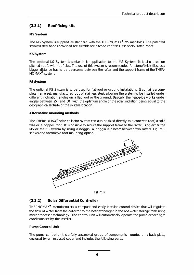
10. Make sure the COATED SURFACE of the absorber in the tube is uppermost when installed.
11. The collector tubes should be covered if the system has not been filled and the tubes are exposed to the sun for extended periods (more than 1 day).
12. Gloves and eye protection should be worn when handling glass.
Avoid any sudden shock to tubes. Avoid scratching the glass collector
tubes, as this will reduce their strength.
Throughout this handbook various sugges-tions have been made for system design and installation. You are strongly advised to follow these suggestions, however final design of any installation is left to the dis-cretion of the installer. This manual was correct at the time of going to print but, as part of a continual product improvement, Thermomax� re-serves the right to update and amend specifications without notice. The Thermomax� Solar Collector is pat-ented worldwide.
2
Technical product description
(3.0) How does a Thermomax system work
The two main components of the THERMOMAX� solar collector system are the THERMOMAX� Memotron� Evacuated Solar Collector Tube and the THERMOMAX� Manifold. Complete roof fixing k its and pump control units are available as accessories. THERMOMAX� MEMOTRON� Evacuated Heat-Pipe Solar Collectors offer the following fea-tures: - High performance - Low heat capacity and high heat
transfer - Thermal diode operation – Heat
flow only in one direction (Tube to manifold)
- Control of maximum temperature - High durability - Freedom from corrosion problems - Freedom from cold weather/frost
problems - Low maintenance effort - Easy installation of single or mul-
tiple units (3.1) The THERMOMAX�
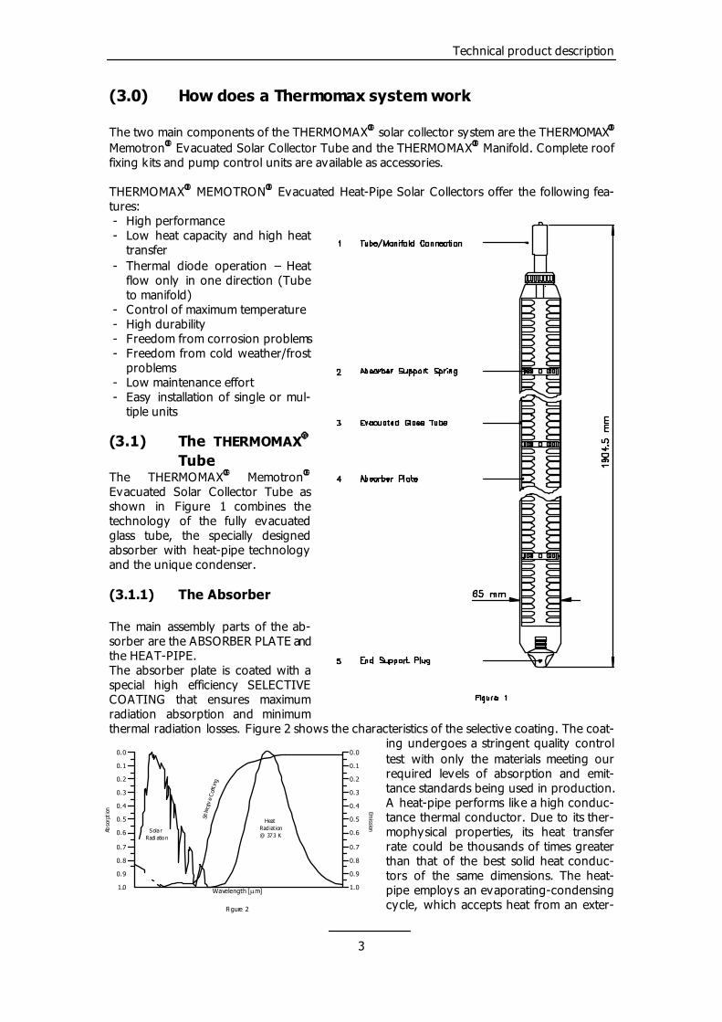
Tube The THERMOMAX Memotron Evacuated Solar Collector Tube as shown in Figure 1 combines the technology of the fully evacuated glass tube, the specially designed absorber with heat-pipe technology and the unique condenser.
� �
(3.1.1) The Absorber
3
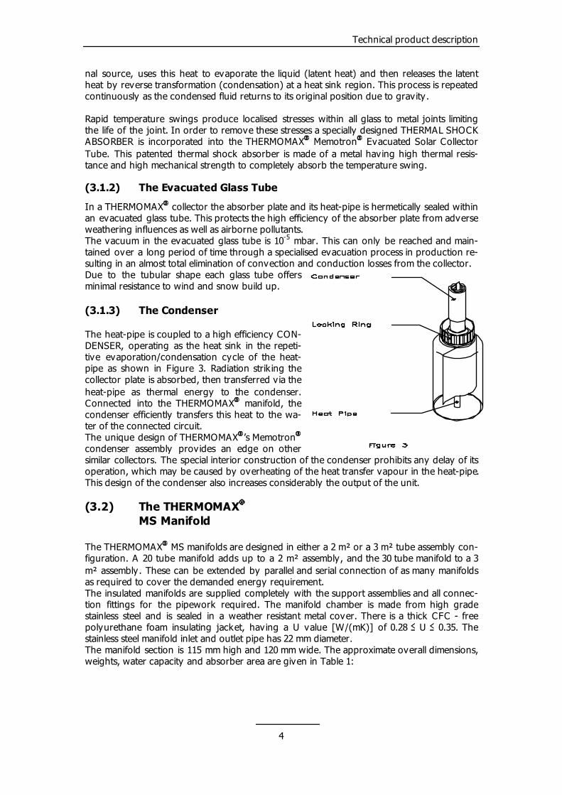
The main assembly parts of the ab-sorber are the ABSORBER PLATE and the HEAT-PIPE. The absorber plate is coated with a special high efficiency SELECTIVE COATING that ensures maximum radiation absorption and minimum thermal radiation losses. Figure 2 shows the characteristics of the selective coating. The coat-
ing undergoes a stringent quality control test with only the materials meeting our required levels of absorption and emit-tance standards being used in production. A heat-pipe performs like a high conduc-tance thermal conductor. Due to its ther-mophysical properties, its heat transfer rate could be thousands of times greater than that of the best solid heat conduc-tors of the same dimensions. The heat-pipe employs an evaporating-condensing cycle, which accepts heat from an exter-
Wavelength [�m]
Abso
rpti
on
Sola rRadi ation
0.9
1.0
0.8
0.7
0.6
0.4
0.5
0.3
0.1
0.2
0.0
Sele
c tiv
e C
oat i
n g
Emission
HeatRadiat ion @ 373 K
Fi gure 2
0.9
1.0
0.8
0.6
0.7
0.4
0.5
0.3
0.1
0.2
0.0
Technical product description
nal source, uses this heat to evaporate the liquid (latent heat) and then releases the latent heat by reverse transformation (condensation) at a heat sink region. This process is repeated continuously as the condensed fluid returns to its original position due to gravity. Rapid temperature swings produce localised stresses within all glass to metal joints limiting the life of the joint. In order to remove these stresses a specially designed THERMAL SHOCK ABSORBER is incorporated into the THERMOMAX� Memotron Evacuated Solar Collector Tube. This patented thermal shock absorber is made of a metal having high thermal resis-tance and high mechanical strength to completely absorb the temperature swing.
�
(3.1.2) The Evacuated Glass Tube
In a THERMOMAX collector the absorber plate and its heat-pipe is hermetically sealed within an evacuated glass tube. This protects the high efficiency of the absorber plate from adverse weathering influences as well as airborne pollutants.
�
The vacuum in the evacuated glass tube is 10-5 mbar. This can only be reached and main-tained over a long period of time through a specialised evacuation process in production re-sulting in an almost total elimination of convection and conduction losses from the collector. Due to the tubular shape each glass tube offers minimal resistance to wind and snow build up. (3.1.3) The Condenser
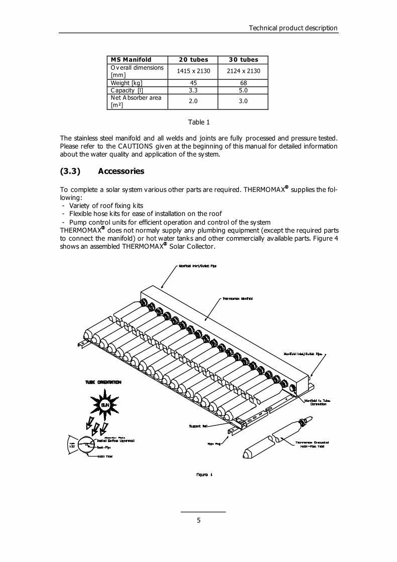
The heat-pipe is coupled to a high efficiency CON-DENSER, operating as the heat sink in the repeti-tive evaporation/condensation cycle of the heat-pipe as shown in Figure 3. Radiation strik ing the collector plate is absorbed, then transferred via the heat-pipe as thermal energy to the condenser. Connected into the THERMOMAX� manifold, the condenser efficiently transfers this heat to the wa-ter of the connected circuit. The unique design of THERMOMAX�’s Memotron condenser assembly provides an edge on other similar collectors. The special interior construction of the condenser prohibits any delay of its operation, which may be caused by overheating of the heat transfer vapour in the heat-pipe. This design of the condenser also increases considerably the output of the unit.
�
(3.2) The THERMOMAX�
MS Manifold
The THERMOMAX� MS manifolds are designed in either a 2 m² or a 3 m² tube assembly con-figuration. A 20 tube manifold adds up to a 2 m² assembly, and the 30 tube manifold to a 3 m² assembly. These can be extended by parallel and serial connection of as many manifolds as required to cover the demanded energy requirement. The insulated manifolds are supplied completely with the support assemblies and all connec-tion fittings for the pipework required. The manifold chamber is made from high grade stainless steel and is sealed in a weather resistant metal cover. There is a thick CFC - free polyurethane foam insulating jacket, having a U value [W/(mK)] of 0.28 � U � 0.35. The stainless steel manifold inlet and outlet pipe has 22 mm diameter. The manifold section is 115 mm high and 120 mm wide. The approximate overall dimensions, weights, water capacity and absorber area are given in Table 1:
4
Technical product description
MS Manifold 20 tubes 30 tubes O v erall dimensions [mm]
1415 x 2130 2124 x 2130
Weight [kg] 45 68 C apacity [l] 3.3 5.0 Net A bsorber area [m²]
2.0 3.0
Table 1
The stainless steel manifold and all welds and joints are fully processed and pressure tested. Please refer to the CAUTIONS given at the beginning of this manual for detailed information about the water quality and application of the system. (3.3) Accessories
To complete a solar system various other parts are required. THERMOMAX supplies the fol-lowing:
�
- Variety of roof fixing k its - Flexible hose kits for ease of installation on the roof - Pump control units for efficient operation and control of the system THERMOMAX� does not normaly supply any plumbing equipment (except the required parts to connect the manifold) or hot water tanks and other commercially available parts. Figure 4 shows an assembled THERMOMAX� Solar Collector.
5
Technical product description
(3.3.1) Roof fixing kits
MS System The MS System is supplied as standard with the THERMOMAX MS manifolds. The patented stainless steel bands provided are suitable for pitched roof tiles, especially slated roofs.
�
KS System The optional KS System is similar in its application to the MS System. It is also used on pitched roofs with roof tiles. The use of this system is recommended for stone/brick tiles, as a bigger distance has to be overcome between the rafter and the support frame of the THER-MOMAX� system. FS System The optional FS System is to be used for flat roof or ground installations. It contains a com-plete frame set, manufactured out of stainless steel, allowing the system to be installed under different inclination angles on a flat roof or the ground. Basically the heat-pipe works under angles between 25° and 50° with the optimum angle of the solar radiation being equal to the geographical latitude of the system location. Alternative mounting methods The THERMOMAX� solar collector system can also be fixed directly to a concrete roof, a solid wall or a copper roof. It is possible to secure the support frame to the rafter using either the MS or the KS system by using a noggin. A noggin is a beam between two rafters. Figure 5 shows one alternative roof mounting option.
Figure 5
(3.3.2) Solar Differential Controller
THERMOMAX� manufacturers a compact and easily installed control device that will regulate the flow of water from the collector to the heat exchanger in the hot water storage tank using microprocessor technology. The control unit will automatically operate the pump according to conditions set by the installer. Pump Control Unit The pump control unit is a fully assembled group of components mounted on a back plate, enclosed by an insulated cover and includes the following parts:
6

Technical product description
- Expansion vessel (18 l, 6 bar) - Pressure relief valve (opening pressure 5 bar) with pressure gauge - Filling loop including valve, hose connector, flexible hose Controllers
THERMOMAX� manufacturers a range of multi-functional microprocessor units providing com-plete control for the solar heating system. The microprocessor technology used in the manufacture ensures the collected energy from the sun is transferred efficiently and har-nessed under optimum conditions. From the easy to understand SMT 100 to the more sophis-ticated SMT 400 via a middle of the range SMT 300, the units provide users with valuable information about their THERMOMAX� solar collector system. System Kit / Active Pack The Active Pack contains all functional parts of the Pump Control Unit, without the back plate and the insulation cover, to allow a more flexible installation where sufficient space for install-ing a Pump Control Unit is not available.
7
Performance
(4.0) How does a THERMOMAX� system perform
(4.1) Solar Fundamentals
All solar collector systems have the sun as common energy source. The perform-ance depends therefore on the conversion of the solar radiation into useful thermal energy and to transfer it to the hot water system. The ability to convert solar energy into thermal energy is expressed by the optical efficiency of the system � . The two fac-tors k and k relate to the system's ability to transfer the energy gained. Equation 4.1 combines the three empirical values to determine the efficiency of the collector system.
0
1 2
(4.1) G
kG
k2
210��
�����
����
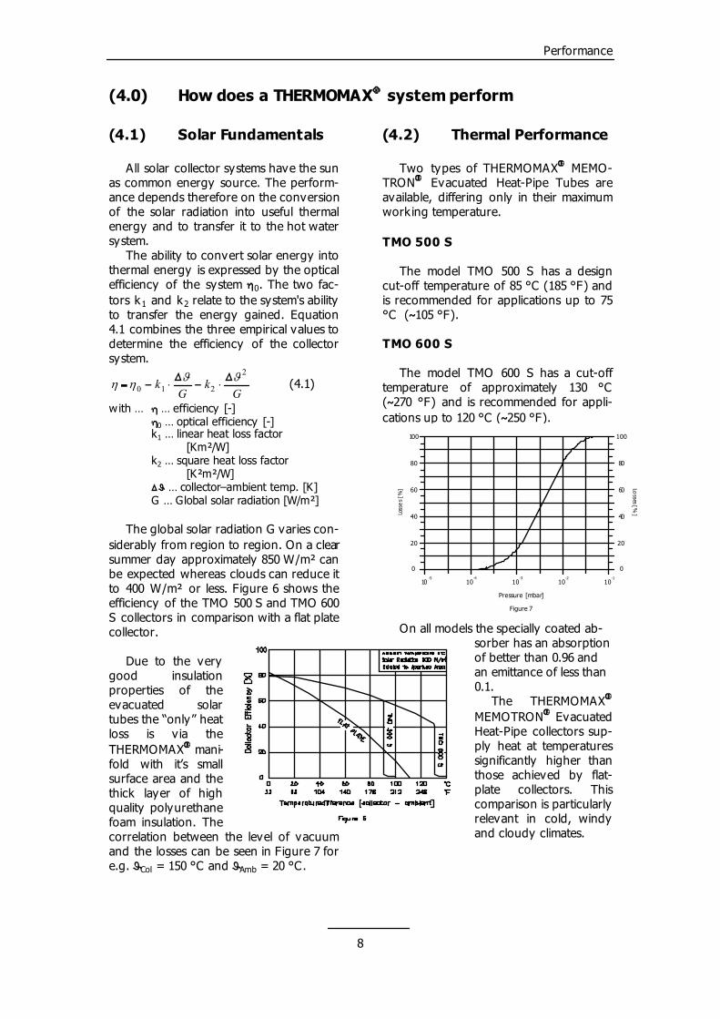
with … � … efficiency [-] �0 … optical efficiency [-] k1 … linear heat loss factor [Km²/W] k … square heat loss factor 2 [K²m²/W] �� … collector–ambient temp. [K] G … Global solar radiation [W/m²] The global solar radiation G varies con-siderably from region to region. On a clear summer day approximately 850 W/m² can be expected whereas clouds can reduce it to 400 W/m² or less. Figure 6 shows the efficiency of the TMO 500 S and TMO 600 S collectors in comparison with a flat plate collector. Due to the very good insulation properties of the evacuated solar tubes the “only” heat loss is v ia the THERMOMAX� mani-fold with it’s small surface area and the thick layer of high quality polyurethane foam insulation. The correlation between the level of vacuum and the losses can be seen in Figure 7 for e.g. �Col = 150 °C and � = 20 °C. Amb
(4.2) Thermal Performance
Two types of THERMOMAX� MEMO-TRON� Evacuated Heat-Pipe Tubes are available, differing only in their maximum working temperature. TMO 500 S The model TMO 500 S has a design cut-off temperature of 85 °C (185 °F) and is recommended for applications up to 75 °C (�105 °F). TMO 600 S The model TMO 600 S has a cut-off temperature of approximately 130 °C (�270 °F) and is recommended for appli-cations up to 120 °C (�250 °F).
On all models the specially coated ab-sorber has an absorption of better than 0.96 and an emittance of less than 0.1. The THERMOMAX MEMOTRON Evacuated Heat-Pipe collectors sup-ply heat at temperatures significantly higher than those achieved by flat-plate collectors. This comparison is particularly relevant in cold, windy and cloudy climates.
0
20
40
60
80
100
Pressure [mbar]
Loss
es
[%] Lo
sses [%]
0
20
40
60
100
80
10-5
10-4
10-3
10-2
10-1
Figure 7
�
�
8
Performance
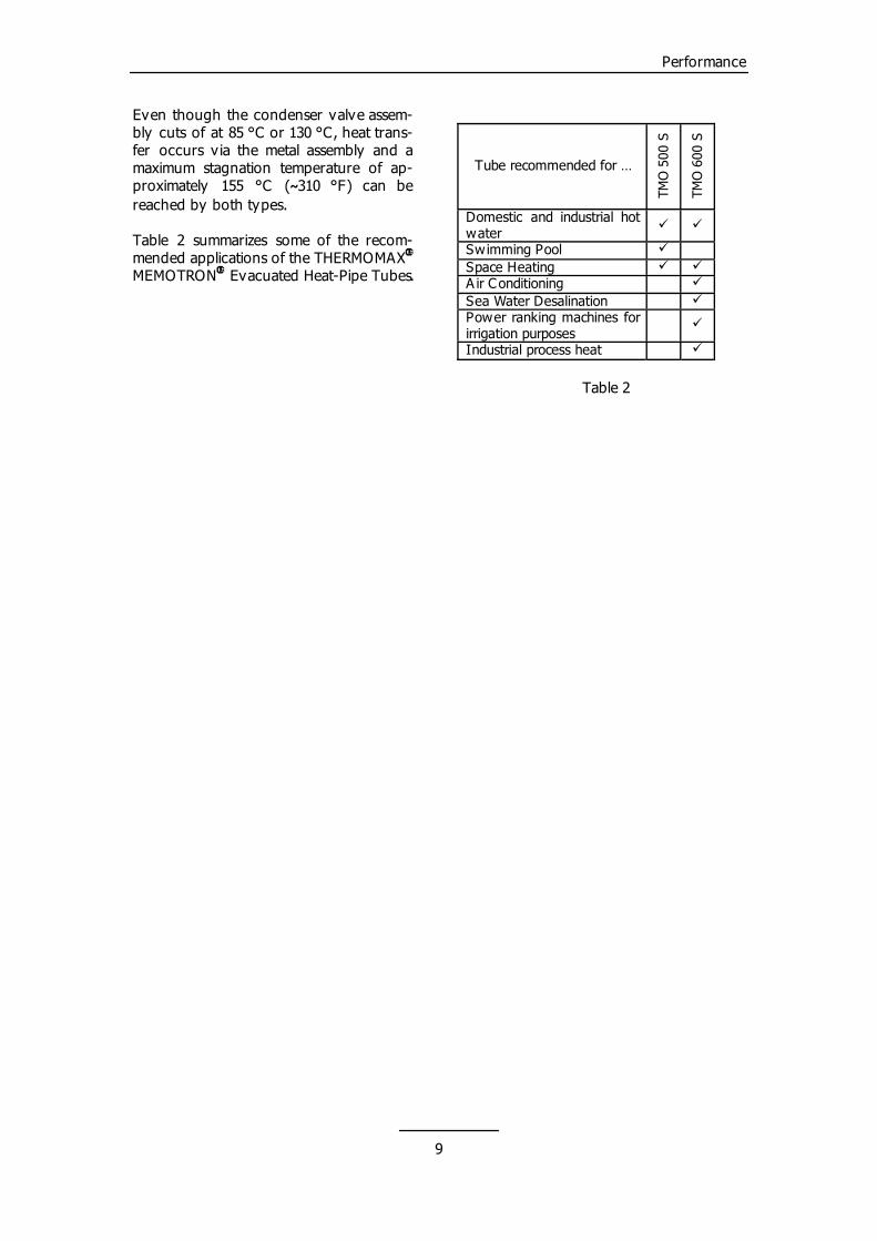
Even though the condenser valve assem-bly cuts of at 85 °C or 130 °C, heat trans-fer occurs v ia the metal assembly and a maximum stagnation temperature of ap-proximately 155 °C (�310 °F) can be reached by both types. Table 2 summarizes some of the recom-mended applications of the THERMOMAX MEMOTRON Evacuated Heat-Pipe Tubes.
�
�
Tube recommended for …
TMO
500
S
TMO
600
S
Domestic and industrial hot water
� �
Swimming Pool � Space Heating � � A ir Conditioning � Sea Water Desalination � Power ranking machines for irrigation purposes
�
Industrial process heat �
Table 2
9
System design
(5.0) How to design a THERMOMAX� system
The first step to ensure enjoyment of your THERMOMAX MEMOTRON Evacu-ated Heat-Pipe System over a long period of time is to design and specify the collec-tor size and the associated components correctly.
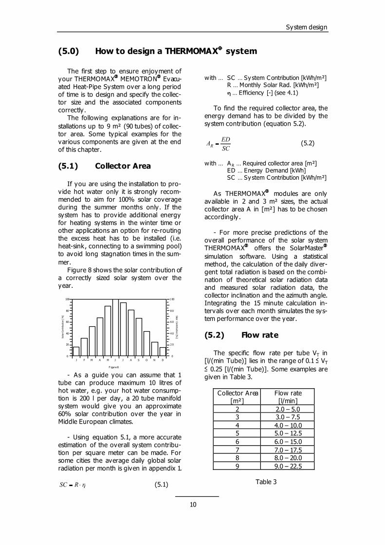
7 7.0 – 17.5
� �
The following explanations are for in-stallations up to 9 m² (90 tubes) of collec-tor area. Some typical examples for the various components are given at the end of this chapter.
8 8.0 – 20.0
(5.1) Collector Area
If you are using the installation to pro-vide hot water only it is strongly recom-mended to aim for 100% solar coverage during the summer months only. If the system has to provide additional energy for heating systems in the winter time or other applications an option for re-routing the excess heat has to be installed (i.e. heat-sink, connecting to a swimming pool) to avoid long stagnation times in the sum-mer.
9 9.0 – 22.5
Figure 8 shows the solar contribution of a correctly sized solar system over the year.
- As a guide you can assume that 1 tube can produce maximum 10 litres of hot water, e.g. your hot water consump-tion is 200 l per day, a 20 tube manifold system would give you an approximate 60% solar contribution over the year in Middle European climates.
Table 3
0
20
40
60
80
100
Sola
r Con
tribu
tion
[%]
0
2 0
4 0
6 0
1 00
8 0
J
F igure 8
F M A M J J A S O N D
Solar Contribution [%]
- Using equation 5.1, a more accurate estimation of the overall system contribu-tion per square meter can be made. For some cities the average daily global solar radiation per month is given in appendix 1.
��� RSC (5.1)
with … SC … Sy stem Contribution [kWh/m²] R … Monthly Solar Rad. [kWh/m²] � … Efficiency [-] (see 4.1) To find the required collector area, the energy demand has to be div ided by the system contribution (equation 5.2).
(5.2)
SCEDAR �
with … A R … Required collector area [m²] ED … Energy Demand [kWh] SC … Sy stem Contribution [kWh/m²] As THERMOMAX� modules are only available in 2 and 3 m² sizes, the actual collector area A in [m²] has to be chosen accordingly. - For more precise predictions of the overall performance of the solar system THERMOMAX offers the SolarMaster simulation software. Using a statistical method, the calculation of the daily diver-gent total radiation is based on the combi-nation of theoretical solar radiation data and measured solar radiation data, the collector inclination and the azimuth angle. Integrating the 15 minute calculation in-tervals over each month simulates the sys-tem performance over the year.
� �
(5.2) Flow rate
The specific flow rate per tube VT in [l/(min Tube)] lies in the range of 0.1 � VT � 0.25 [l/(min Tube)]. Some examples are given in Table 3.
Collector Area [m²]
Flow rate [l/min]
2 2.0 – 5.0 3 3.0 – 7.5 4 4.0 – 10.0 5 5.0 – 12.5 6 6.0 – 15.0
10
System design
Multiplied with the collector area re-spectively the number of tubes, where 10 tubes equal 1 m², the system flow rate can be determined as shown in equation 5.3.
S In analogy to the correlation in electricity where the Ohm’s law applies, every resistance (= resistance) causes a pressure drop (= voltage drop) as soon as there is a flow rate (= cur-rent). Table 5 gives a rough guide which pump should be used in domes-tic installations depending on the col-lector area.
TTS nVV �� (5.3)
with … V … Sy stem flow rate [l/min] s V T … F low rate per tube [l/(minTube)] nT … Number of tubes [-] (rises in multiples of 10) Or to convert the system flow rate VS into the unit [m³/h] circulation pumps are generally specified in use equation 5.4.
1006]
min[][
3
��
lVhmV SS (5.4)
The more tubes that are connected in series, the higher the specific flow rate VT should be. THERMOMAX� strongly rec-ommends not to connect more than 90 to 100 tubes in series. The flow rate further affects the achievable temperature difference �T in [K] between the collector outlet and the solar tank return. This value is used to switch the circulation pump in the system on and off. The longer the pipework in the installation, the bigger �T should be to avoid toggling of the pump. Through ob-servation and some experience the flow rate can be easily altered after completion of the installation if necessary using a ball valve installed in the pipework or the taco-setter on the pump control unit. (5.3) Pipework
Some recommended pipe sizes are given in Table 4.
Flow rate [l/min] Copper pipe size [mm]
2 – 6 @ �=1m/s Cu 15 x 1 7 – 10 @ �=1m/s Cu 18 x 1 12.5 – 17.5 @ �=1m/s Cu 22 x 1 17.5 – 22.5 @ �=1m/s Cu 28 x 1.5
Table 4
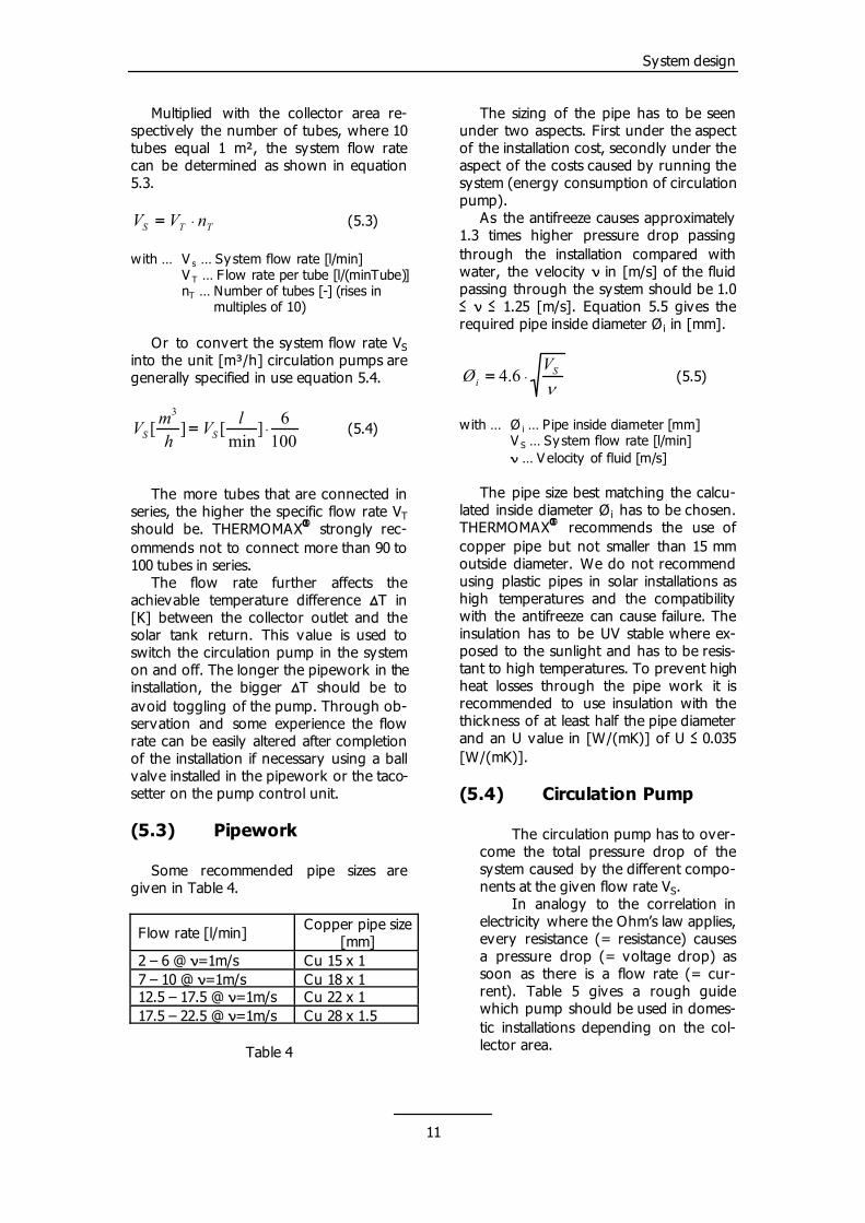
The sizing of the pipe has to be seen under two aspects. First under the aspect of the installation cost, secondly under the aspect of the costs caused by running the system (energy consumption of circulation pump). As the antifreeze causes approximately 1.3 times higher pressure drop passing through the installation compared with water, the velocity � in [m/s] of the fluid passing through the system should be 1.0 � � � 1.25 [m/s]. Equation 5.5 gives the required pipe inside diameter Øi in [mm].
�
Si
VØ �� 6.4 (5.5)
with … Ø i … Pipe inside diameter [mm] V S … Sy stem flow rate [l/min] � … Velocity of fluid [m/s] The pipe size best matching the calcu-lated inside diameter Ø has to be chosen. THERMOMAX� recommends the use of copper pipe but not smaller than 15 mm outside diameter. We do not recommend using plastic pipes in solar installations as high temperatures and the compatibility with the antifreeze can cause failure. The insulation has to be UV stable where ex-posed to the sunlight and has to be resis-tant to high temperatures. To prevent high heat losses through the pipe work it is recommended to use insulation with the thickness of at least half the pipe diameter and an U value in [W/(mK)] of U � 0.035 [W/(mK)].
i
(5.4) Circulation Pump
The circulation pump has to over-come the total pressure drop of the system caused by the different compo-nents at the given flow rate V .
11
System design
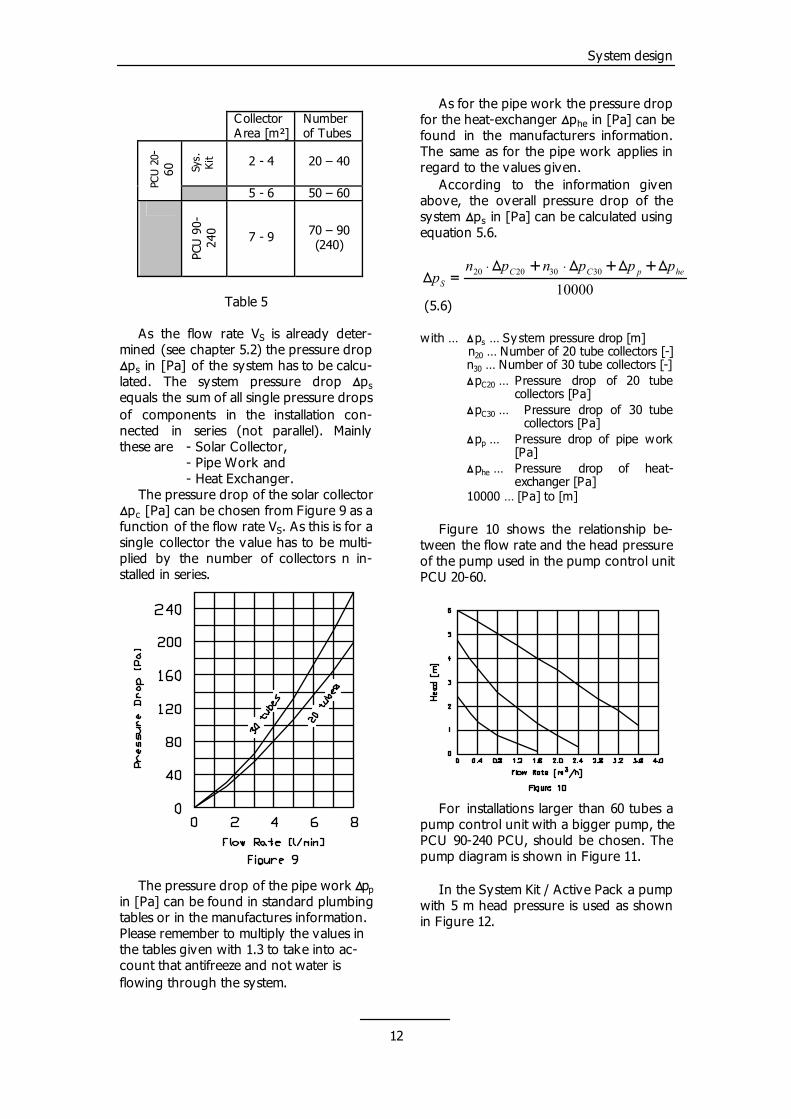
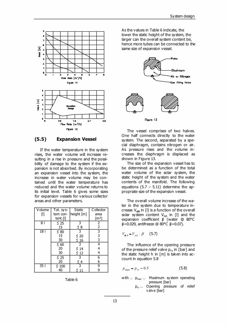
For installations larger than 60 tubes a pump control unit with a bigger pump, the PCU 90-240 PCU, should be chosen. The pump diagram is shown in Figure 11.
Collector A rea [m²]
Number of Tubes
In the System Kit / Active Pack a pump with 5 m head pressure is used as shown in Figure 12.
Sys.
Kit
PCU 2
0-60
2 - 4 20 – 40
5 - 6 50 – 60
PCU
90-
240 7 - 9 70 – 90
(240)
Table 5
As the flow rate V is already deter-mined (see chapter 5.2) the pressure drop �p in [Pa] of the system has to be calcu-lated. The system pressure drop �p equals the sum of all single pressure drops of components in the installation con-nected in series (not parallel). Mainly these are - Solar Collector,
S
s
s
- Pipe Work and - Heat Exchanger. The pressure drop of the solar collector �pc [Pa] can be chosen from Figure 9 as a function of the flow rate V . As this is for a single collector the value has to be multi-plied by the number of collectors n in-stalled in series.
S
The pressure drop of the pipe work ��pp in [Pa] can be found in standard plumbing tables or in the manufactures information. Please remember to multiply the values in the tables given with 1.3 to take into ac-count that antifreeze and not water is flowing through the system.
As for the pipe work the pressure drop for the heat-exchanger �p in [Pa] can be found in the manufacturers information. The same as for the pipe work applies in regard to the values given.
he
According to the information given above, the overall pressure drop of the system �ps in [Pa] can be calculated using equation 5.6.
1000030302020 hepCC
S
pppnpnp
�����������
(5.6) with … �p … Sy stem pressure drop [m] s n20 … Number of 20 tube collectors [-] n30 … Number of 30 tube collectors [-] �pC20 … Pressure drop of 20 tube
collectors [Pa] �pC30 … Pressure drop of 30 tube
collectors [Pa] �p … Pressure drop of pipe work
[Pa] p
�phe … Pressure drop of heat-exchanger [Pa]
10000 … [Pa] to [m] Figure 10 shows the relationship be-tween the flow rate and the head pressure of the pump used in the pump control unit PCU 20-60.
12
System design
The vessel comprises of two halves. One half connects directly to the water system. The second, separated by a spe-cial diaphragm, contains nitrogen or air. As pressure rises and the volume in-creases the diaphragm is displaced as shown in Figure 13. The size of the expansion vessel has to be determined as a function of the total water volume of the solar system, the static height of the system and the water contents of the manifold. The following equations (5.7 – 5.11) determine the ap-propriate size of the expansion vessel.
(5.5) Expansion Vessel
If the water temperature in the system rises, the water volume will increase re-sulting in a rise in pressure and the possi-bility of damage to the system if the ex-pansion is not absorbed. By incorporating an expansion vessel into the system, the increase in water volume may be con-tained until the water temperature has reduced and the water volume returns to its initial level. Table 6 gives some sizes for expansion vessels for various collector areas and other parameters.
The overall volume increase of the wa-ter in the system due to temperature in-crease V�� in [l] is a function of the overall solar system content Vsys in [l] and the expansion coefficient � (water @ 80°C �=0.029, antifreeze @ 80°C �=0.07).
V olume [l]
Tot. sy s-tem con-tent [l]
Static height [m]
(5.7)
Collector area [m²]
8 l
The influence of the opening pressure of the pressure relief valve prv in [bar] and the static height h in [m] is taken into ac-count in equation 5.8
� 25 15
3 � 8
(5.8) with … pmax … Maximum sy stem operating
pressure [bar]
2 2
prv … Opening pressure of relief v alv e [bar]
18 l � 80 15 30
3 � 20 � 16
3 3 3
� 60 20 30
3 � 14 � 12
4 4 4
� 25 20
3 � 4
6 6
35 l � 100 40
3 � 11
9 9
Table 6
As the values in Table 6 indicate, the lower the static height of the system, the larger can the overall system content be, hence more tubes can be connected to the same size of expansion vessel.
��
��� sysVV
5.0max �� rvpp
13
System design
hpp hd ��� 1.0 (5.9)
with … p … set pressure for diaphragm [bar] d ph … Pressure in highest point of sy s-
tem (e.g. 0.5 bar) [bar] 0.1 … [m] to [bar] h … static height [m] To ensure a sufficient volume of water in the system at all times a minimum vol-ume Vc in [l] must be present in the ex-pansion vessel in the cold condition. With Vc and the values calculated before the nominal size of the expansion vessel V in [l] can be calculated with equations 5.10 and 5.11.
n
(5.10)
][1015.0 lVV sysc ���
with … V c … Water volume in expansion ves-sel in cold sy stem condition [l] (minimum 1 litre)
V sys … Overall solar sy stem content [l]
(5.11)
� � � �
d
colcolcn pp
pVnVVV
�
������ �
max
max 1�
with … V n … Nominal v olume of expansion vessel [l]
V … Water volume in expansion ves-sel in cold sy stem condition [l]
c
V �� … Volume increase due to temp. increase [l]
n … Number of manifolds installed [-]
col
V col … Water volume of single mani-fold [l]
pmax … Maximum sy stem operating pressure [bar]
p … Set pressure for diaphragm [bar] d
Having calculated the nominal size of the expansion vessel Vn the closest avail-able vessel size will be chosen. (5.6) Hydraulics
(5.6.1) Collector System
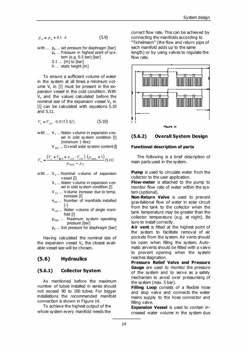
As mentioned before the maximum number of tubes installed in series should not exceed 90 to 100 tubes. For bigger installations the recommended manifold connection is shown in Figure 14. To achieve the highest output of the whole system every manifold needs the
correct flow rate. This can be achieved by connecting the manifolds according to “Tichelmann” (the flow and return pipe of each manifold adds up to the same length) or by using valves to regulate the flow rate.
(5.6.2) Overall System Design
Functional description of parts The following is a brief description of main parts used in the system. Pump is used to circulate water from the collector to the user application. Flow-meter is attached to the pump to monitor flow rate of water within the sys-tem (optional). Non-Return Valve is used to prevent gravitational flow of water in solar circuit from the tank to the collector when the tank temperature may be greater than the collector temperature (e.g. at night). Be sure to install correctly. Air vent is fitted at the highest point of the system to facilitate removal of air pockets from the system. Air vents should be open when filling the system. Auto-matic airvents should be fitted with a valve to prevent opening when the system reaches stagnation. Pressure Relief Valve and Pressure Gauge are used to monitor the pressure of the system and to serve as a safety mechanism to avoid over pressurising of the system (max. 5 bar). Filling Loop consists of a flexible hose and stop valve and connects the water mains supply to the hose connector and filling valve. Expansion Vessel is used to contain in-creased water volume in the system due
14
System design
to rise in temperature, and hence in-creased pressure, of water.
Flush and Drain assembly is used to flush the system before filling with anti-freeze and to drain it, if necessary.
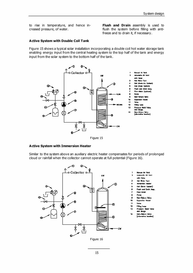
Active System with Double Coil Tank Figure 15 shows a typical solar installation incorporating a double coil hot water storage tank enabling energy input from the central heating system to the top half of the tank and energy input from the solar system to the bottom half of the tank.
F igure 15
Active System with Immersion Heater Similar to the system above an auxiliary electric heater compensates for periods of prolonged cloud or rainfall when the collector cannot operate at full potential (Figure 16).
F igure 16
15
Installation details
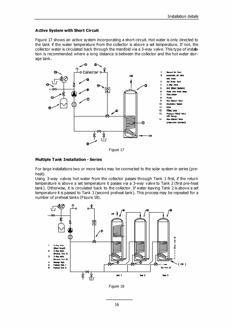
Active System with Short Circuit Figure 17 shows an active system incorporating a short circuit. Hot water is only directed to the tank if the water temperature from the collector is above a set temperature. If not, the collector water is circulated back through the manifold v ia a 3-way valve. This type of installa-tion is recommended where a long distance is between the collector and the hot water stor-age tank.
F igure 17
Multiple Tank Installation - Series For large installations two or more tanks may be connected to the solar system in series (pre-heat). Using 3-way valves hot water from the collector passes through Tank 1 first, if the return temperature is above a set temperature it passes v ia a 3-way valve to Tank 2 (first pre-heat tank). Otherwise, it is circulated back to the collector. If water leaving Tank 2 is above a set temperature it is passed to Tank 3 (second preheat tank). This process may be repeated for a number of preheat tanks (Figure 18).
F igure 18
16
Installation details
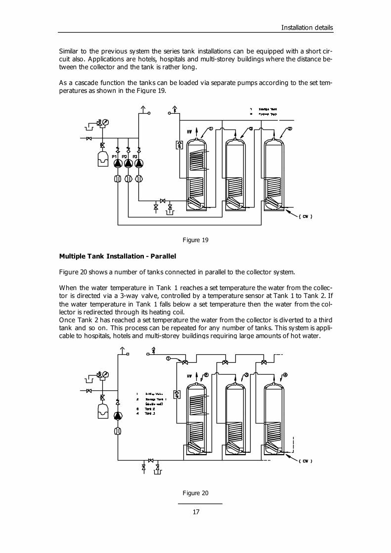
Similar to the previous system the series tank installations can be equipped with a short cir-cuit also. Applications are hotels, hospitals and multi-storey buildings where the distance be-tween the collector and the tank is rather long. As a cascade function the tanks can be loaded via separate pumps according to the set tem-peratures as shown in the Figure 19.
F igure 19
Multiple Tank Installation - Parallel Figure 20 shows a number of tanks connected in parallel to the collector system. When the water temperature in Tank 1 reaches a set temperature the water from the collec-tor is directed via a 3-way valve, controlled by a temperature sensor at Tank 1 to Tank 2. If the water temperature in Tank 1 falls below a set temperature then the water from the col-lector is redirected through its heating coil. Once Tank 2 has reached a set temperature the water from the collector is diverted to a third tank and so on. This process can be repeated for any number of tanks. This system is appli-cable to hospitals, hotels and multi-storey buildings requiring large amounts of hot water.
F igure 20
17
Installation details
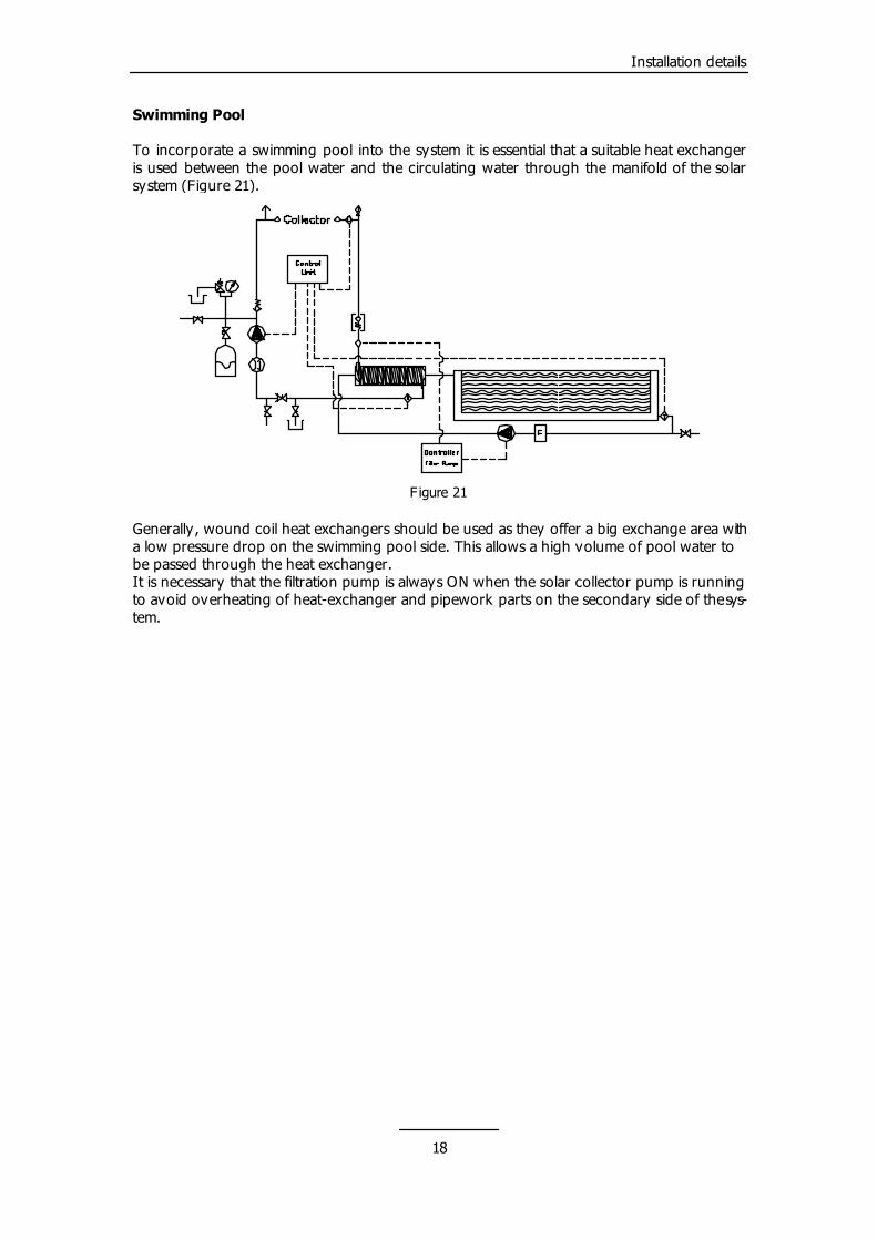
Swimming Pool To incorporate a swimming pool into the system it is essential that a suitable heat exchanger is used between the pool water and the circulating water through the manifold of the solar system (Figure 21).
F igure 21
Generally, wound coil heat exchangers should be used as they offer a big exchange area with a low pressure drop on the swimming pool side. This allows a high volume of pool water to be passed through the heat exchanger. It is necessary that the filtration pump is always ON when the solar collector pump is running to avoid overheating of heat-exchanger and pipework parts on the secondary side of the sys-tem.
18
Installation details
(6.0) How to install a THERMOMAX System�
This chapter explains the installation procedures for the THERMOMAX� Evacu-ated Solar Collector System with the vari-ous roof fixing k its. (6.1) General
Due to the overall weight of the unit it MUST BE MOUNTED SECURELY TO A STRONG SECTION OF THE ROOF. Please observe the following simple precautions to ensure maximum efficiency from your THERMOMAX Solar Energy Collector assembly.
�
Locate the solar collector system so that the tubes receive maximum sunshine through the day with no or minimum shading. NOTE: The coated surface of the absorber must face uppermost (±30°) and as south facing as possible (Azimuth an-gle). The solar collector system can, be mounted at any suitable angle between 25° and almost vertical position (Inclina-tion Angle). The recommended angle is the same as the geographical latitude of the collector location. In areas where local water is known to be hard or aggressive, a heat exchanger must be used and the use of a water sof-tener is recommended, otherwise regular cleaning of the system will be required. In areas where the chloride ion concentration is greater than 40 ppm a heat exchanger must be used in the hot water storage tank. The solar system should be filled with distilled or dechlorinated water. Check with your local
ater authorities. w CAUTIONARY NOTES: - Make sure sufficient space is left be-
tween the manifold and roof apex for ease of working on pipework within the loft span.
- Wear gloves and safety goggles when working with glass tubes.
- Do not use sharp objects to open the covers or the box as this may scratch or damage the glass tube.
- Do not remove the tubes from pack-aging until ready to assemble.
- Connect the manifold, all the pipe-work and the pump first before in-stalling the tubes.
Pipes running horizontally should always be installed rising slightly to avoid the creation of air pockets. Note that when installing the collector and pipe work it is important that all local authority regulations, relevant technical and safety standards are adhered to. (6.2) Manifold Connections
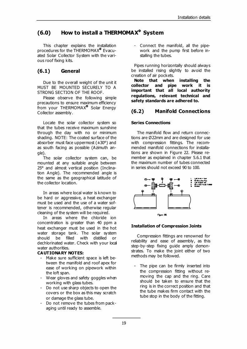
Series Connections The manifold flow and return connec-tions are Ø22mm and are designed for use with compression fittings. The recom-mended manifold connections for installa-tions are shown in Figure 22. Please re-member as explained in chapter 5.6.1 that the maximum number of tubes connected in series should not exceed 90 to 100.
Installation of Compression Joints Compression fittings are renowned for reliability and ease of assembly, as this step-by-step fixing guide amply demon-strates. To make the joint either of two methods may be followed. - The pipe can be firmly inserted into
the compression fitting without re-moving the cap and the ring. Care should be taken to ensure that the ring is in the correct position and that the tube makes firm contact with the tube stop in the body of the fitting.
19
Installation details
- Or the cap and the ring can be removed, slipped on to the pipe in logical sequence and the tube fully inserted into the compression fit-ting.
In both cases, tightening of the cap-nut is effected by hand as far as possible, fol-lowed by appropriate turning of the same with a suitable spanner while a second spanner is used to hold the fitting in posi-tion.
20
Installation details
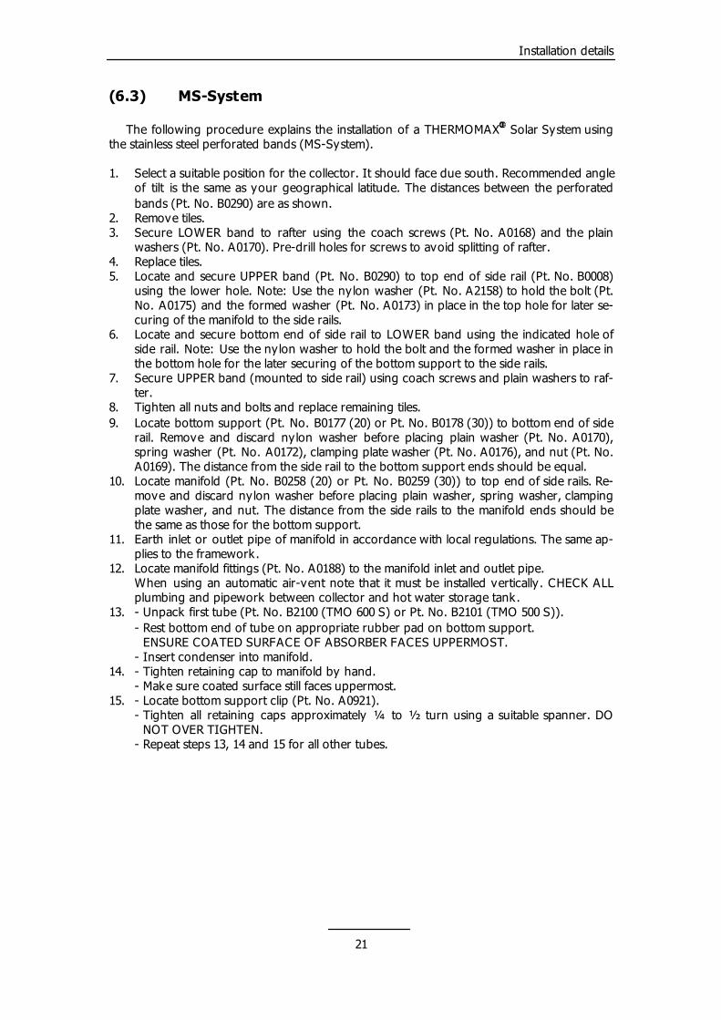
(6.3) MS-System
The following procedure explains the installation of a THERMOMAX� Solar System using the stainless steel perforated bands (MS-System). 1. Select a suitable position for the collector. It should face due south. Recommended angle
of tilt is the same as your geographical latitude. The distances between the perforated bands (Pt. No. B0290) are as shown.
2. Remove tiles. 3. Secure LOWER band to rafter using the coach screws (Pt. No. A0168) and the plain
washers (Pt. No. A0170). Pre-drill holes for screws to avoid splitting of rafter. 4. Replace tiles. 5. Locate and secure UPPER band (Pt. No. B0290) to top end of side rail (Pt. No. B0008)
using the lower hole. Note: Use the nylon washer (Pt. No. A2158) to hold the bolt (Pt. No. A0175) and the formed washer (Pt. No. A0173) in place in the top hole for later se-curing of the manifold to the side rails.
6. Locate and secure bottom end of side rail to LOWER band using the indicated hole of side rail. Note: Use the nylon washer to hold the bolt and the formed washer in place in the bottom hole for the later securing of the bottom support to the side rails.
7. Secure UPPER band (mounted to side rail) using coach screws and plain washers to raf-ter.
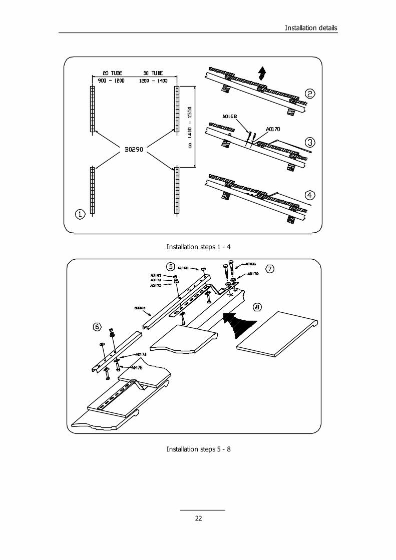
8. Tighten all nuts and bolts and replace remaining tiles. 9. Locate bottom support (Pt. No. B0177 (20) or Pt. No. B0178 (30)) to bottom end of side
rail. Remove and discard nylon washer before placing plain washer (Pt. No. A0170), spring washer (Pt. No. A0172), clamping plate washer (Pt. No. A0176), and nut (Pt. No. A0169). The distance from the side rail to the bottom support ends should be equal.
10. Locate manifold (Pt. No. B0258 (20) or Pt. No. B0259 (30)) to top end of side rails. Re-move and discard nylon washer before placing plain washer, spring washer, clamping plate washer, and nut. The distance from the side rails to the manifold ends should be the same as those for the bottom support.
11. Earth inlet or outlet pipe of manifold in accordance with local regulations. The same ap-plies to the framework.
12. Locate manifold fittings (Pt. No. A0188) to the manifold inlet and outlet pipe. When using an automatic air-vent note that it must be installed vertically. CHECK ALL
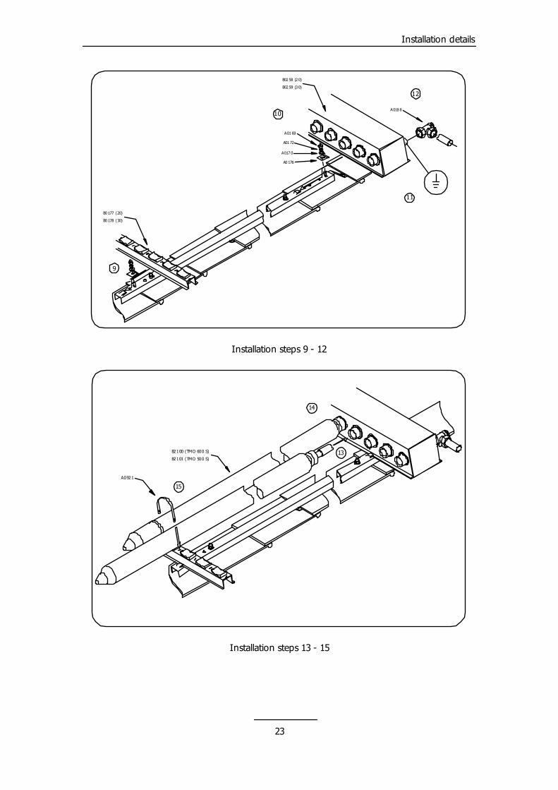
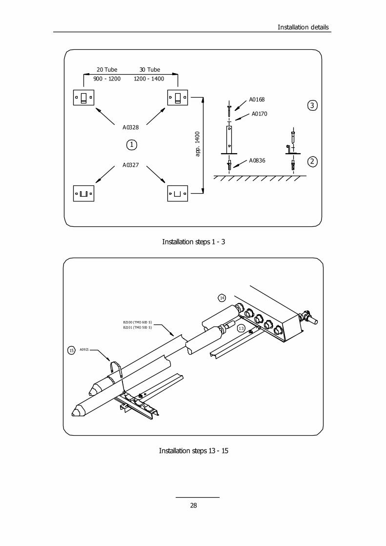
plumbing and pipework between collector and hot water storage tank. 13. - Unpack first tube (Pt. No. B2100 (TMO 600 S) or Pt. No. B2101 (TMO 500 S)). - Rest bottom end of tube on appropriate rubber pad on bottom support. ENSURE COATED SURFACE OF ABSORBER FACES UPPERMOST. - Insert condenser into manifold. 14. - Tighten retaining cap to manifold by hand. - Make sure coated surface still faces uppermost. 15. - Locate bottom support clip (Pt. No. A0921). - Tighten all retaining caps approximately ¼ to ½ turn using a suitable spanner. DO
NOT OVER TIGHTEN. - Repeat steps 13, 14 and 15 for all other tubes.
21
Installation details
Installation steps 1 - 4
Installation steps 5 - 8
22
Installation details
B0 177 (20)
B0 178 (30)
A01 69
A01 72
A017 0
A0 176
9
B02 59 (3 0)
B02 58 (2 0)
10A018 8
12
11
Installation steps 9 - 12
B2100 (TMO 600 S)
B2101 (TMO 500 S)13
14
15A0921
Installation steps 13 - 15
23
Installation details
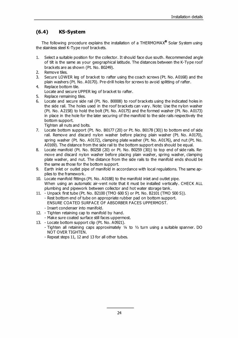
(6.4) KS-System
The following procedure explains the installation of a THERMOMAX Solar System using the stainless steel K-Type roof brackets.
�
1. Select a suitable position for the collector. It should face due south. Recommended angle
of tilt is the same as your geographical latitude. The distances between the K-Type roof brackets are as shown (Pt. No. B0249).
2. Remove tiles. 3. Secure LOWER leg of bracket to rafter using the coach screws (Pt. No. A0168) and the
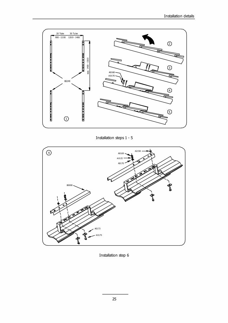
plain washers (Pt. No. A0170). Pre-drill holes for screws to avoid splitting of rafter. 4. Replace bottom tile. Locate and secure UPPER leg of bracket to rafter. 5. Replace remaining tiles. 6. Locate and secure side rail (Pt. No. B0008) to roof brackets using the indicated holes in
the side rail. The holes used in the roof brackets can vary. Note: Use the nylon washer (Pt. No. A2158) to hold the bolt (Pt. No. A0175) and the formed washer (Pt. No. A0173) in place in the hole for the later securing of the manifold to the side rails respectively the bottom support.
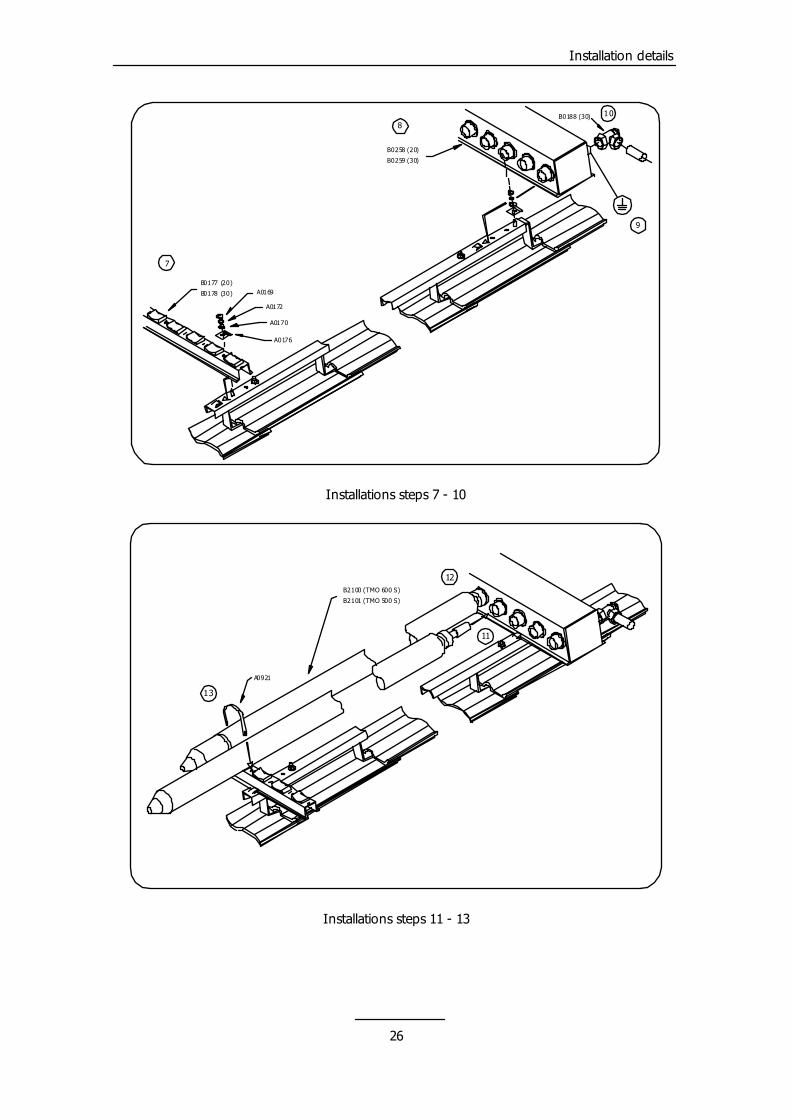
Tighten all nuts and bolts. 7. Locate bottom support (Pt. No. B0177 (20) or Pt. No. B0178 (30)) to bottom end of side
rail. Remove and discard nylon washer before placing plain washer (Pt. No. A0170), spring washer (Pt. No. A0172), clamping plate washer (Pt. No. A0176), and nut (Pt. No. A0169). The distance from the side rail to the bottom support ends should be equal.
8. Locate manifold (Pt. No. B0258 (20) or Pt. No. B0259 (30)) to top end of side rails. Re-move and discard nylon washer before placing plain washer, spring washer, clamping plate washer, and nut. The distance from the side rails to the manifold ends should be the same as those for the bottom support.
9. Earth inlet or outlet pipe of manifold in accordance with local regulations. The same ap-plies to the framework.
10. Locate manifold fittings (Pt. No. A0188) to the manifold inlet and outlet pipe. When using an automatic air-vent note that it must be installed vertically. CHECK ALL
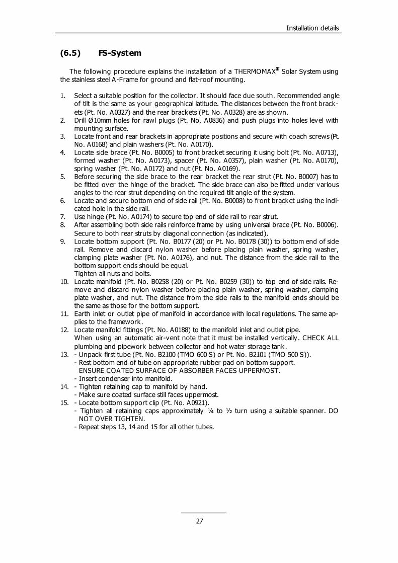
plumbing and pipework between collector and hot water storage tank. 11. - Unpack first tube (Pt. No. B2100 (TMO 600 S) or Pt. No. B2101 (TMO 500 S)). - Rest bottom end of tube on appropriate rubber pad on bottom support. ENSURE COATED SURFACE OF ABSORBER FACES UPPERMOST. - Insert condenser into manifold. 12. - Tighten retaining cap to manifold by hand. - Make sure coated surface still faces uppermost. 13. - Locate bottom support clip (Pt. No. A0921). - Tighten all retaining caps approximately ¼ to ½ turn using a suitable spanner. DO
NOT OVER TIGHTEN. - Repeat steps 11, 12 and 13 for all other tubes.
24
Installation details
20 Tube
900 - 12 00 120 0 - 1400
30 Tube
B0249
A0168
A0170
app.
140
0 - 1
500
1
2
3
4
5
Installation steps 1 - 5
A0169
A0172
A0170
A0175
A0173
A21586
B0008
Installation step 6
25
Installation details
B0177 (20)
B0178 (30) A0169
A0172
A0170
A0176
7
B0258 (20)
B0259 (30)
8
9
B0188 (30) 10
Installations steps 7 - 10
B2100 (TMO 600 S)
B2101 (TMO 500 S)
11
12
13
A0921
Installations steps 11 - 13
26
Installation details
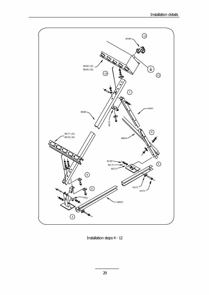
(6.5) FS-System
The following procedure explains the installation of a THERMOMAX� Solar System using the stainless steel A-Frame for ground and flat-roof mounting. 1. Select a suitable position for the collector. It should face due south. Recommended angle
of tilt is the same as your geographical latitude. The distances between the front brack-ets (Pt. No. A0327) and the rear brackets (Pt. No. A0328) are as shown.
2. Drill Ø10mm holes for rawl plugs (Pt. No. A0836) and push plugs into holes level with mounting surface.
3. Locate front and rear brackets in appropriate positions and secure with coach screws (Pt. No. A0168) and plain washers (Pt. No. A0170).
4. Locate side brace (Pt. No. B0005) to front bracket securing it using bolt (Pt. No. A0713), formed washer (Pt. No. A0173), spacer (Pt. No. A0357), plain washer (Pt. No. A0170), spring washer (Pt. No. A0172) and nut (Pt. No. A0169).
5. Before securing the side brace to the rear bracket the rear strut (Pt. No. B0007) has to be fitted over the hinge of the bracket. The side brace can also be fitted under various angles to the rear strut depending on the required tilt angle of the system.
6. Locate and secure bottom end of side rail (Pt. No. B0008) to front bracket using the indi-cated hole in the side rail.
7. Use hinge (Pt. No. A0174) to secure top end of side rail to rear strut. 8. After assembling both side rails reinforce frame by using universal brace (Pt. No. B0006).
Secure to both rear struts by diagonal connection (as indicated). 9. Locate bottom support (Pt. No. B0177 (20) or Pt. No. B0178 (30)) to bottom end of side
rail. Remove and discard nylon washer before placing plain washer, spring washer, clamping plate washer (Pt. No. A0176), and nut. The distance from the side rail to the bottom support ends should be equal.
Tighten all nuts and bolts. 10. Locate manifold (Pt. No. B0258 (20) or Pt. No. B0259 (30)) to top end of side rails. Re-
move and discard nylon washer before placing plain washer, spring washer, clamping plate washer, and nut. The distance from the side rails to the manifold ends should be the same as those for the bottom support.
11. Earth inlet or outlet pipe of manifold in accordance with local regulations. The same ap-plies to the framework.
12. Locate manifold fittings (Pt. No. A0188) to the manifold inlet and outlet pipe. When using an automatic air-vent note that it must be installed vertically. CHECK ALL
plumbing and pipework between collector and hot water storage tank. 13. - Unpack first tube (Pt. No. B2100 (TMO 600 S) or Pt. No. B2101 (TMO 500 S)). - Rest bottom end of tube on appropriate rubber pad on bottom support. ENSURE COATED SURFACE OF ABSORBER FACES UPPERMOST. - Insert condenser into manifold. 14. - Tighten retaining cap to manifold by hand. - Make sure coated surface still faces uppermost. 15. - Locate bottom support clip (Pt. No. A0921). - Tighten all retaining caps approximately ¼ to ½ turn using a suitable spanner. DO
NOT OVER TIGHTEN. - Repeat steps 13, 14 and 15 for all other tubes.
27
Installation details
20 Tube
900 - 1200 1200 - 1400
30 Tube
app.
140
0
A0328
A0327
A0168
A0170
A0836
3
2
1
Installation steps 1 - 3
Installation steps 13 - 15
B2100 (TMO 600 S)
B2101 (TMO 500 S) 13
14
A092115
28
Installation details
B000 5
A0173
A0713
A0357
A017 0
A01 72
A0 169
4
5
B0007
B0008
6
A017
4
7
B000 6
8B0177 ( 20)
B0178 ( 30)
9
B0259 ( 30)
B0258 ( 20)
1011
A018812
Installation steps 4 - 12
29
Installation details
(6.6) Alternative Methods
It is possible to secure the side rails to rafter or tiles that are nailed in and cannot be re-moved using either perforated bands (5.3) or brackets (5.4) a noggin can be installed. A nog-gin is a beam secured between two rafters. - Coach screws to noggin or rafter: This method is used only if at least 50mm (2”) of screw thread can be secured into noggin or rafter. - Stainless steel threaded rod: This method is used if the tile depth or uneven roof prevents use of coach screws, or if collector is to be secured directly to wall. For further explanation see also Figure 5 chapter 3.3.1. (6.7) Commissioning
Before filling the system with the antifreeze and bringing it up to it’s operating pressure the following steps should be carried out. 1. Check all joints have been soldered and all compression joints have been tightened.
Open all valves in the system (pump ball valves, check valves, etc.). 2. Make temporary hose connection between mains supply and flush and drain assembly.
Close middle valve of assembly and flush system thoroughly via the two other valves to remove all dirt and solder residues.
3. Open the middle valve of the flush and drain assembly, drain the system and close the inlet and outlet valve of the flush and drain assembly. Recheck all joints and connections for leaks.
4. Use a hand pump or a pumped garden spray bottle to fill the required amount of anti-freeze/inhibitor into the system through the filling loop. The amount of anti-freeze/inhibitor depends on the location of the system and the overall system volume (ratio antifreeze/water = frost protection).
5. Connect hose to water mains supply and fill system to its operating pressure. 6. Open all air-vents and run circulation pump on manual mode. Make sure no anti-
freeze/inhibitor will be drained through opened air-vents. It may be necessary to top up the system pressure in the first few days of operation as
dissolved air in the antifreeze/inhibitor is expelled through the automatic air-vent. 7. Adjust system flow rate to the right value. Begin with speed level 1 of circulation pump
with fully opened flow-meter and adapt speed level and flow-meter (if used) settings ac-cordingly.
8. Adapt controller settings according to system properties as described in the controller manual.
30
Maintenance
(7.0) How to maintain a Thermomax� System
(7.1) Periodic Checks
- Ensure that no physical damage has occurred to the tubes and remove any debris that may have accumulated.
- Check the flow and return pipework between collector and storage tank. Check all connections for leaks and en-sure all components are operating cor-rectly.
- Check that the system pressure is maintained at the set value. If the sys-tem pressure repeatedly drops more than 0.5 bar below the set pressure check the system for leaks.
(7.2) Optional Checks
The checks listed in this section depend on the components used in the system installation. - Each spring vent system as some air
will come out of the system solution during the course of the year.
- Check the pressure to see if the set value is still maintained. If top up is necessary connect hose to water
mains, fill hose with water to avoid in-troduction of air into system.
Connect hose to filling loop, open valve very slowly until pressure is increased to set value.
- To check antifreeze/inhibitor concen-tration, draw off a small sample at the drain cock and place in the freezer compartment. Remove when frozen then measure temperature at “slush” stage i.e. when ice and liquid are both present. Temperature should be the same or lower than the minimum ex-pected for the locality.
(7.3) Five Yearly Checks
- If using antifreeze/inhibitor, every five years the system should be completely drained and flushed then refilled with new antifreeze/inhibitor.
- Check all insulation of pipework and the condition of the sensors, especially the manifold sensor.
- Check the seals where the flow and return connections pass through the roof tiles.
31
Troubleshooting
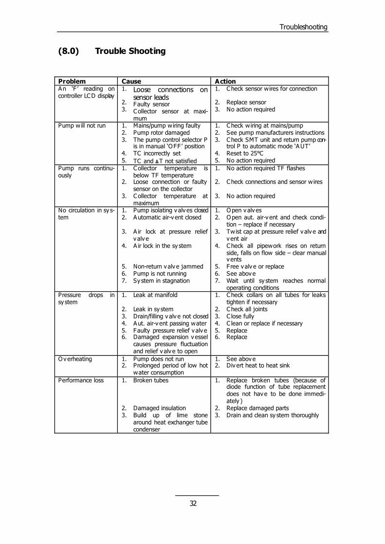
(8.0) Trouble Shooting
No action required TF flashes Check connections and sensor wires
2. 3. 4.
Problem Cause Action
No action required
No circulation in sy s-tem
5. 6.
Check collars on all tubes for leaks tighten if necessary
An ‘F ’ reading on controller LCD display
1.
1. 2.
Check all joints C lose fully C lean or replace if necessary
2. 3.
Loose connections on sensor leads
3. 4.
Replace Replace
Overheating
Faulty sensor Collector sensor at maxi-mum
1.
5. 6.
1. 2.
Pump does not run
2. 3.
7.
Pump isolating valv es closed Automatic air-v ent closed
Prolonged period of low hot water consumption
1. 2.
Check sensor wires for connection Replace sensor No action required
A ir lock at pressure relief v alv e A ir lock in the sy stem
See above Div ert heat to heat sink
Performance loss
Pump will not run
Non-return valv e jammed Pump is not running
1.
1. 2. 3.
1. 2.
4. 5.
Mains/pump wiring faulty Pump rotor damaged
3. 4.
Broken tubes
The pump control selector P is in manual ‘OFF ’ position TC incorrectly set TC and �T not satisfied
5.
Damaged insulation Build up of lime stone around heat exchanger tube condenser
1.
1. 2. 3.
6. 7.
Open valv es
4. 5.
Check wiring at mains/pump
Open aut. air-v ent and check condi-tion – replace if necessary Twist cap at pressure relief v alv e and vent air Check all pipework rises on return side, falls on flow side – clear manual v ents F ree valv e or replace
2. 3.
Replace broken tubes (because of diode function of tube replacement does not have to be done immedi-ately ) Replace damaged parts
See pump manufacturers instructions Check SMT unit and return pump con-trol P to automatic mode ‘AUT’ Reset to 25°C
See above Wait until sy stem reaches normal operating conditions
Drain and clean sy stem thoroughly
No action required Pump runs continu-ously
Pressure drops in sy stem
1.
1. 2.
2. 3. 4. 5.
3.
Collector temperature is below TF temperature Loose connection or faulty sensor on the collector
6.
Leak at manifold
Collector temperature at maximum
1.
Leak in sy stem Drain/filling valv e not closed Aut. air-v ent passing water
2. 3.
Faulty pressure relief v alv e Damaged expansion vessel causes pressure fluctuation and relief v alv e to open
1.
Sy stem in stagnation
2. 3.
32
Appendix
(9.0) Appendix
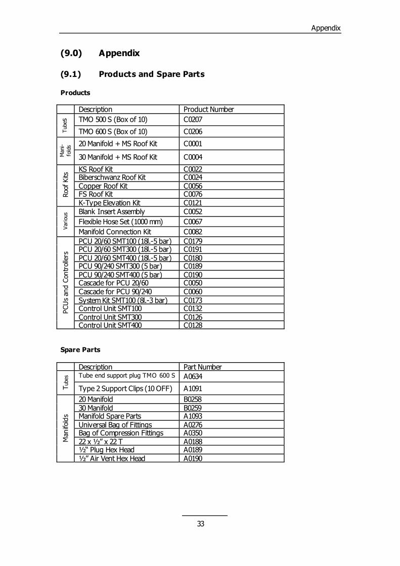
(9.1) Products and Spare Parts
C0191
Manifold Spare Parts A1093
Products Description
PCU 20/60 SMT400 (18l.-5 bar) C0180
Universal Bag of Fittings A0276
Product Number
Tub
es
PCU 90/240 SMT300 (5 bar) C0189
Bag of Compression Fittings A0350
TMO 500 S (Box of 10) C0207
PCU 90/240 SMT400 (5 bar) C0190
22 x ½” x 22 T
TMO 600 S (Box of 10) C0206
Cascade for PCU 20/60 C0050
A0188 ½“ Plug Hex Head
20 Manifold + MS Roof Kit C0001
Man
i-fo
lds
Cascade for PCU 90/240
A0189
30 Manifold + MS Roof Kit
C0060
½” Air Vent Hex Head A0190
C0004
KS Roof Kit
Roof
Kits
System Kit SMT100 (8l.-3 bar) C0173
C0022
Control Unit SMT100 C0132
Biberschwanz Roof Kit C0024
Control Unit SMT300 C0126
Copper Roof Kit C0056
Control Unit SMT400 C0128
FS Roof Kit C0076
K-Type Elevation Kit
Spare Parts
C0121
Var
ious
Description Part Number
Tube
s
Blank Insert Assembly C0052
Tube end support plug TMO 600 S A0634
Flexible Hose Set (1000 mm) C0067
Type 2 Support Clips (10 OFF) A1091
Manifold Connection Kit C0082
20 Manifold
Man
ifold
s
PCU 20/60 SMT100 (18l.-5 bar) C0179
PCU
s an
d Co
ntro
llers
B0258 30 Manifold
PCU 20/60 SMT300 (18l.-5 bar)
B0259
33
Appendix
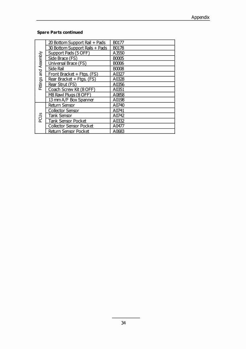
Spare Parts continued
20 Bottom Support Rail + Pads Fi
tting
s an
d As
sem
bly
Tank Sensor Pocket A0332
B0177
Collector Sensor Pocket A0477
30 Bottom Support Rails + Pads B0178
Return Sensor Pocket A0683
Support Pads (5 OFF) A3550
Side Brace (FS) B0005 Universal Brace (FS) B0006 Side Rail B0008 Front Bracket + Ftgs. (FS) A0327 Rear Bracket + Ftgs. (FS) A0328 Rear Strut (FS) A0356 Coach Screw Kit (8 OFF) A0351 M8 Rawl Plugs (8 OFF) A0858 13 mm A/F Box Spanner A0198 Return Sensor A0740
PCU
s Collector Sensor A0741 Tank Sensor A0742
34
Appendix
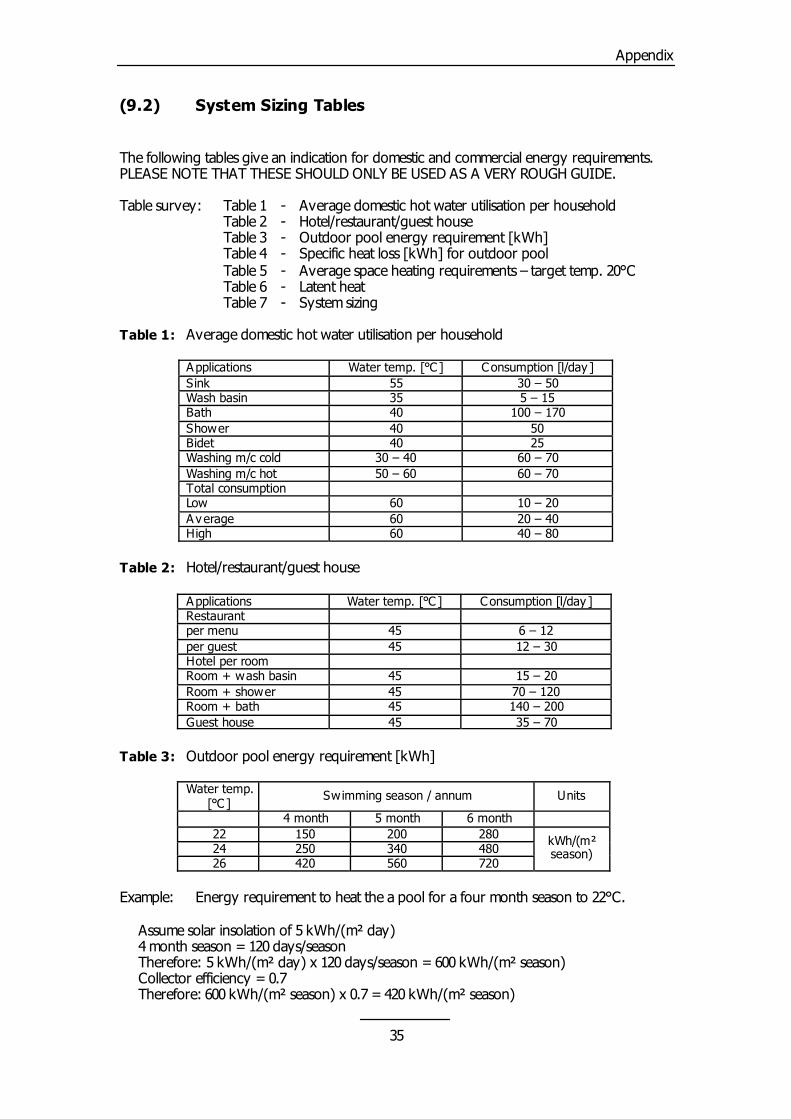
(9.2) System Sizing Tables
The following tables give an indication for domestic and commercial energy requirements. PLEASE NOTE THAT THESE SHOULD ONLY BE USED AS A VERY ROUGH GUIDE.
Table 2: Hotel/restaurant/guest house
Applications
26 420 560
Table survey: Table 1 - Average domestic hot water utilisation per household Table 2 - Hotel/restaurant/guest house
Water temp. [°C ] Consumption [l/day ]
720
Table 3 - Outdoor pool energy requirement [kWh] Table 4 - Specific heat loss [kWh] for outdoor pool Table 5 - Average space heating requirements – target temp. 20°C Table 6 - Latent heat
Restaurant
Example: Energy requirement to heat the a pool for a four month season to 22°C. Assume solar insolation of 5 kWh/(m² day)
Table 7 - System sizing Table 1: Average domestic hot water utilisation per household
per menu 45 6 – 12
4 month season = 120 days/season Therefore: 5 kWh/(m² day) x 120 days/season = 600 kWh/(m² season) Collector efficiency = 0.7
Applications Water temp. [°C ]
per guest 45
Therefore: 600 kWh/(m² season) x 0.7 = 420 kWh/(m² season)
Consumption [l/day ]
12 – 30 Hotel per room
Sink 55 30 – 50 Wash basin
Room + wash basin
35 5 – 15
45 15 – 20
Bath 40 100 – 170
Room + shower 45 70 – 120
Shower 40 50
Room + bath 45 140 – 200
Bidet 40
Guest house 45
25 Washing m/c cold
35 – 70
30 – 40 60 – 70 Washing m/c hot
Table 3: Outdoor pool energy requirement [kWh]
Water temp. [°C ]
Swimming season / annum
50 – 60 60 – 70
Units
Total consumption
4 month 5 month 6 month
Low 60 10 – 20
22 150
Average 60
200 280 kWh/(m² season)
20 – 40 High
24 250
60 40 – 80
340 480
35
Appendix
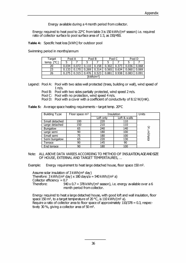
Energy available during a 4 month period from collector.
Table 5: Average space heating requirements – target temp. 20°C
Building Type
Example: Energy requirement to heat large detached house, floor space 150 m².
Energy required to heat pool to 22°C from table 3 is 150 kWh/(m² season) i.e. required ratio of collector surface to pool surface area of 1:3, as 150/450.
Table 4: Specific heat loss [kWh] for outdoor pool
Insulation F loor space m² Units
Assume solar insulation of 3 kWh(m² day) Therefore: 3 kWh/(m² day) x 180 days/a = 540 kWh/(m² a) Collector efficiency = 0.7 Therefore: 540 x 0.7 = 378 kWh/(m² season), i.e. energy available over a 6
month period from collector.
Swimming period in months/annum
Energy required to heat a large detached house, with good loft and wall insulation, floor
space 150 m², to a target temperature of 20 °C, is 110 kWh/(m² a).
Target
temp. [°C ] Pool A Pool B Pool C
Loft & walls
Pool D
Small detached 100 220 110
5 7 5 7
Large detached
KWh/
(m²
a)
5 7 5
150 210 110
7 20
Bungalow 65
0.034 0.072 0.110 0.158
240 140
0.302 0.373 0.036
Large semi 90
0.068 23
180 100
0.133 0.170 0.269 0.314
Small semi 75 180
0.565 0.634 0.060
100
0.069 26
Semi bungalow 65 220
0.275 0.315 0.476 0.523
130 Terrace
0.881 0.938 0.083
90 145 90
0.091 [kWh/m²]
End terrace
Legend: Pool A: Pool with two sides well protected (trees, building or wall), wind speed of
1 m/s. Pool B: Pool with two sides partially protected, wind speed 2 m/s.
90 180 100
Pool C: Pool with no protection, wind speed 4 m/s. Pool D: Pool with a cover with a coefficient of conductivity of 8.12 W/(mK).
Note: ALL ABOVE DATA VARIES ACCORDING TO METHOD OF INSULATION, AGE AND SIZE
OF HOUSE, EXTERNAL AND TARGET TEMPERTAURES, …
Loft only
Require a ratio of collector area to floor space of approximately 110/378 = 0.3, respec-tively 30 %, giving a collector area of 50 m².
36
Appendix
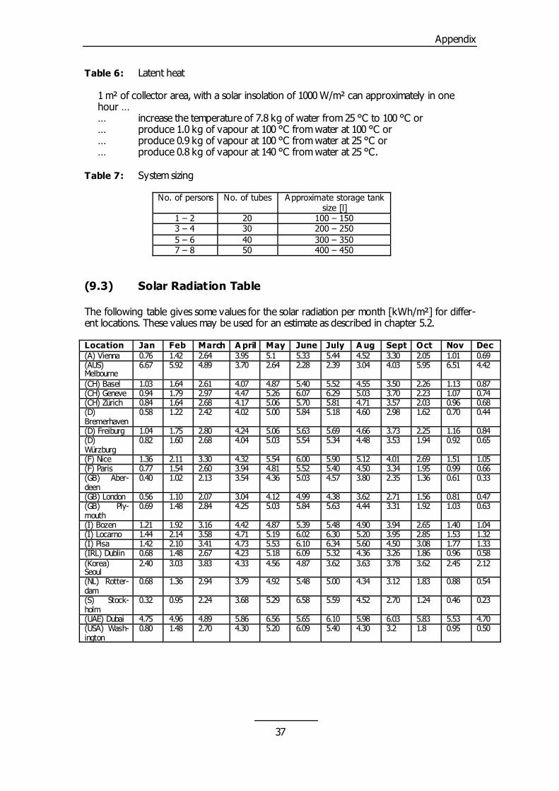
Table 6: Latent heat
0.69 (AUS) Melbourne
6.67
5.00 5.84 5.18 4.60
0.66 (GB) Aber-deen
0.40
5.19 6.02 6.30 5.20
0.54
(S) Stock-holm
0.32
1 m² of collector area, with a solar insolation of 1000 W/m² can approximately in one
hour … … increase the temperature of 7.8 kg of water from 25 °C to 100 °C or … produce 1.0 kg of vapour at 100 °C from water at 100 °C or … produce 0.9 kg of vapour at 100 °C from water at 25 °C or
4.89 3.70 2.64
… produce 0.8 kg of vapour at 140 °C from water at 25 °C. Table 7: System sizing
2.28 2.39 3.04
0.44
(D) Freiburg 1.04
4.57 3.80
No. of persons No. of tubes
4.03 5.95 6.51
1.75 2.80 4.24
2.35 1.36 0.61
2.10 3.41 4.73
0.46
Approximate storage tank size [l]
1 – 2 20
4.42
(CH) Basel 1.03
5.06 5.63 5.69 4.66
0.33
(GB) London 0.56
5.53 6.10 6.34 5.60
0.23
(UAE) Dubai 4.75
100 – 150 3 – 4
1.64 2.61 4.07
3.73 2.25 1.16
1.10 2.07 3.04
4.50 3.08 1.77
4.96 4.89 5.86
30 200 – 250
4.87 5.40 5.52
0.84 (D) Würzburg
4.12 4.99 4.38
1.33 (IRL) Dublin
6.56 5.65 6.10
5 – 6 40 300 – 350
4.55 3.50 2.26 1.13
0.82 1.60 2.68 4.04
3.62 2.71 1.56 0.81
0.68 1.48 2.67 4.23
5.98 6.03 5.83 5.53
7 – 8 50 400 – 450
0.87 (CH) Geneve
5.03 5.54 5.34
0.47 (GB) Ply-mouth
5.18 6.09 5.32
4.70 (USA) Wash-ington
0.94 1.79 2.97
4.48 3.53 1.94
0.69 1.48 2.84
4.36 3.26 1.86
0.80 1.48 2.70
(9.3) Solar Radiation Table
The following table gives some values for the solar radiation per month [kWh/m²] for differ-ent locations. These values may be used for an estimate as described in chapter 5.2.
4.47 5.26 6.07 6.29
0.92 0.65
(F) Nice
4.25 5.03 5.84 5.63
0.96 0.58 (Korea) Seoul
4.30 5.20 6.09 5.40
Location Jan Feb March
5.03 3.70 2.23
1.36 2.11 3.30
4.44 3.31 1.92
2.40 3.03 3.83
4.30 3.2 1.8
A pril May June
1.07 0.74
4.32 5.54 6.00
1.03 0.63
4.33 4.56 4.87
0.95 0.50
July A ug Sept
(CH) Zürich 0.84 1.64 2.68
5.90 5.12 4.01 2.69
(I) Bozen 1.21 1.92 3.16
3.62 3.63 3.78 3.62
Oct Nov Dec
4.17 5.06 5.70
1.51 1.05
4.42 4.87 5.39
2.45 2.12
(A) Vienna 0.76 1.42
5.81 4.71 3.57
(F) Paris 0.77 1.54
5.48 4.90 3.94
(NL) Rotter-dam
0.68 1.36
2.64 3.95 5.1
2.03 0.96 0.68
2.60 3.94 4.81 5.52
2.65 1.40 1.04
2.94 3.79 4.92 5.48
5.33 5.44 4.52 3.30
(D) Bremerhaven
0.58 1.22
5.40 4.50 3.34
(I) Locarno 1.44 2.14
5.00 4.34 3.12
2.05 1.01
2.42 4.02
1.95 0.99
3.58 4.71
1.83 0.88
5.92
2.98 1.62 0.70
1.02 2.13 3.54
3.95 2.85 1.53
0.95 2.24 3.68
4.36 5.03
1.32 (I) Pisa
5.29 6.58 5.59
1.42
4.52 2.70 1.24
37
Appendix
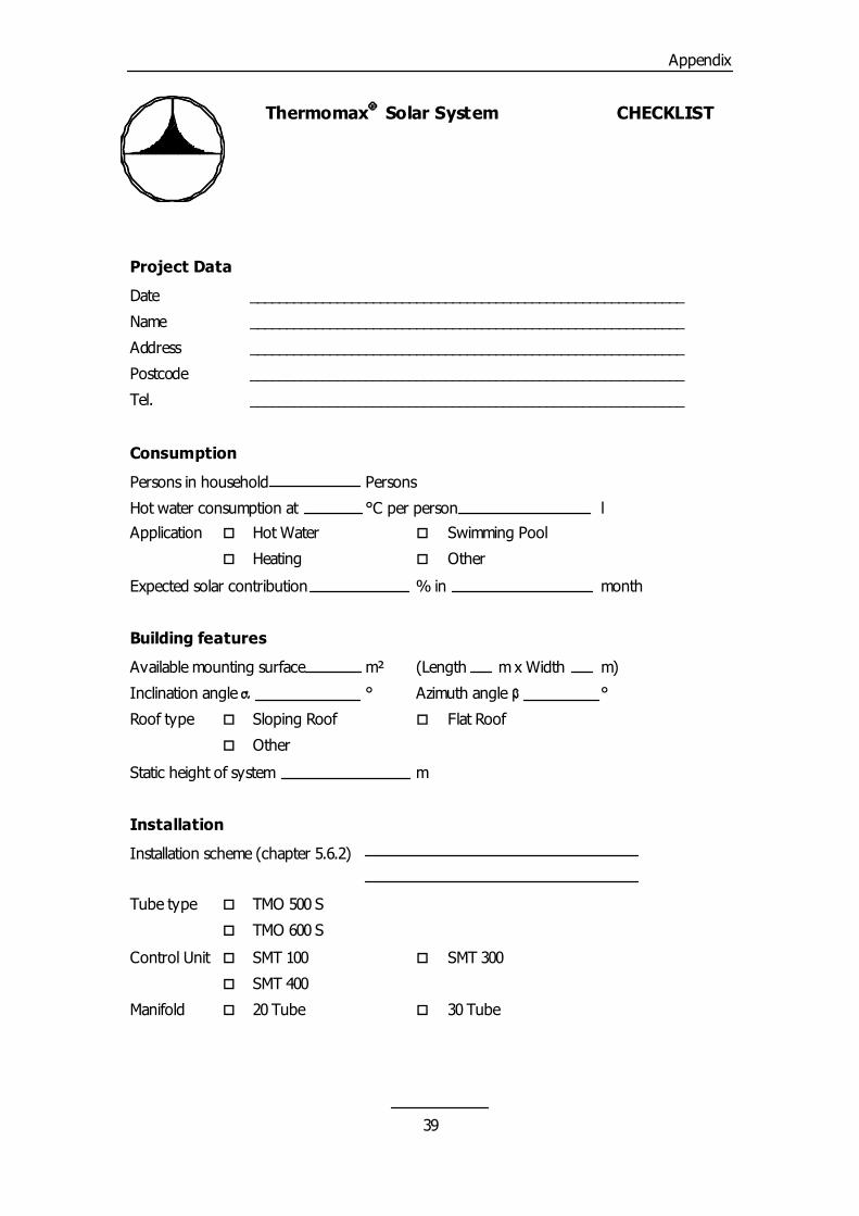
(9.4) Checklist
This checklist will help to collect all the necessary data to design a solar collector system and to give a quotation for it. (9.5) Calculation Sheet
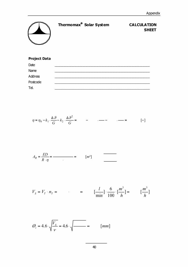
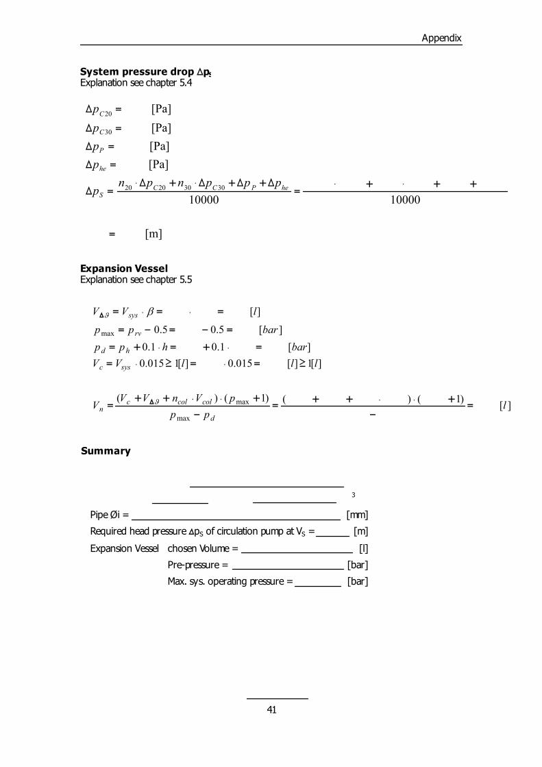
The following chart will help to size the expansion vessel, to determine the overall system flow rate and to calculate the minimum inside pipe diameter required. All calculations are based on the explanations and equations in chapter 5. (9.6) Commissioning Sheet
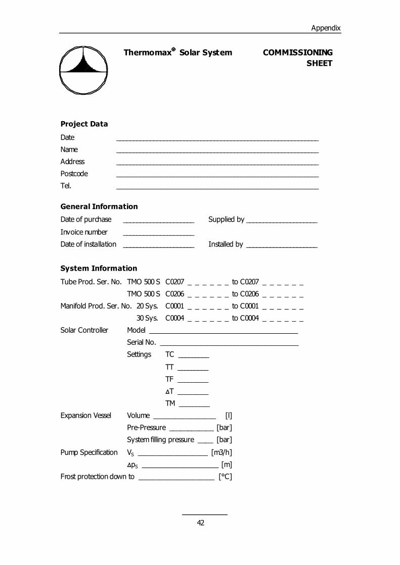
After completion of the installation we recommend to fill in the commissioning sheet and to leave a copy at the location of the solar system for reference.
38
Appendix
Thermomax� Solar System CHECKLIST
Project Data
Date ____________________________________________________________
Name ____________________________________________________________
Address ____________________________________________________________
Postcode ____________________________________________________________
Tel. ____________________________________________________________
Consumption
Persons in household Persons
Hot water consumption at °C per person l Application � Hot Water � Swimming Pool
� Heating � Other
Expected solar contribution % in month
Building features
Available mounting surface m² (Length m x Width m)
Inclination angle � ° Azimuth angle � °
Roof type � Sloping Roof � Flat Roof
� Other
Static height of system m
Installation
Installation scheme (chapter 5.6.2)
Tube type � TMO 500 S
� TMO 600 S
Control Unit � SMT 100 � SMT 300
� SMT 400
Manifold � 20 Tube � 30 Tube
39
Appendix
Thermomax� Solar System CALCULATION SHEET
Project Data
Date ____________________________________________________________
Name ____________________________________________________________
Address ____________________________________________________________
Postcode ____________________________________________________________
Tel. ____________________________________________________________
Collector Efficiency � Explanation see chapter 4.1
2�� ��
CEV
SE
FE
][
210 ������������G
kG
k��
ollector Area AR xplanation see chapter 5.1 alues taken from table 10.3
x 20 Manifold(s) ED
ystem Flow rate VS xplanation see chapter 5.2
x 30 Manifold(s)
= [m²] ²][
mR
AR �
�
�
�
�
�
33
low and return pipe diameter Øi xplanation see chapter 5.3
][ ][1006]
min[
hm
hmlnVV TTS ��������
][
6.46.4 mmVØ Si �����
�
40
Appendix
System pressure drop �pSExplanation see chapter 5.4
[Pa] ��p
[m]
10000
10000
[Pa] [Pa] [Pa]
30302020
30
20
�
������
�����������
��
��
��
hePCCS
he
P
C
C
pppnpnp
ppp
Expansion Vessel Explanation see chapter 5.5
][
)1 () ()1()(
][1][ 015.0 ][1015.0][ 1.0 1.0
][ 5.0 5.0
][
max
max
max
lpp
pVnVVV
lllVVbarhpp
barpp
lVV
d
colcolcn
sysc
hd
rv
sys
��
������
�
������
�������
�������
�����
�����
�
�
�
��
Summary
Chosen collector Area = [m²]
Flow rate VS = [l/min] = [m /h] 3
Pipe Øi = [mm]
Required head pressure �pS of circulation pump at VS = [m]
Expansion Vessel chosen Volume = [l]
Pre-pressure = [bar]
Max. sys. operating pressure = [bar]
41
Appendix
Thermomax� Solar System COMMISSIONING SHEET
Project Data
Date ____________________________________________________________
Name ____________________________________________________________
Address ____________________________________________________________
Postcode ____________________________________________________________
Tel. ____________________________________________________________
General Information
Date of purchase _____________________ Supplied by _____________________
Invoice number _____________________
Date of installation _____________________ Installed by _____________________
System Information
Tube Prod. Ser. No. TMO 500 S C0207 _ _ _ _ _ _ to C0207 _ _ _ _ _ _
TMO 500 S C0206 _ _ _ _ _ _ to C0206 _ _ _ _ _ _
Manifold Prod. Ser. No. 20 Sys. C0001 _ _ _ _ _ _ to C0001 _ _ _ _ _ _
30 Sys. C0004 _ _ _ _ _ _ to C0004 _ _ _ _ _ _
Solar Controller Model ____________________________________________
Serial No. _________________________________________
Settings TC _________
TT _________
TF _________
�T _________
TM _________
Expansion Vessel Volume _________________ [l]
Pre-Pressure ____________ [bar]
System filling pressure ____ [bar]
Pump Specification VS ___________________ [m3/h]
�pS _____________________ [m]
Frost protection down to _____________________ [°C]
42