thesis: design and control of a robotic mouth
TRANSCRIPT

Thesis: Design and control of arobotic mouth
VAN DE VELDE Gabriël-Mathieu
Academic year2015-2016
Master thesis project submitted under the supervision ofProf. dr. ir. Bram VanderborghtProf. dr. ir. Dirk LefeberThe co-supervision ofir. Albert De BeirIn order to be awarded the Master’s Degree inElectromechanical Engineering, Mechatronics


Contents
1 Introduction 11.1 Motivation . . . . . . . . . . . . . . . . . . . . . . . . . . . . . . . . . . . 11.2 Goals . . . . . . . . . . . . . . . . . . . . . . . . . . . . . . . . . . . . . . 21.3 Outline of the thesis . . . . . . . . . . . . . . . . . . . . . . . . . . . . . . 2
2 Literature Review 32.1 Social robots . . . . . . . . . . . . . . . . . . . . . . . . . . . . . . . . . . 32.2 Why do some social robots have a mouth? . . . . . . . . . . . . . . . . . . 42.3 Designing a face robot. . . . . . . . . . . . . . . . . . . . . . . . . . . . . 4
2.3.1 Types and material selection . . . . . . . . . . . . . . . . . . . . . . 52.3.2 Degrees of freedom: quantity, location and direction . . . . . . . . . 52.3.3 Actuators used for face robots . . . . . . . . . . . . . . . . . . . . . 8
2.4 Controlling a face robot . . . . . . . . . . . . . . . . . . . . . . . . . . . . 122.4.1 Control methods: overview . . . . . . . . . . . . . . . . . . . . . . 12
2.5 Text to robot, general outline . . . . . . . . . . . . . . . . . . . . . . . . . 132.5.1 From sentence or audio up to phoneme segmentation . . . . . . . . 142.5.2 From phonemes up to visemes . . . . . . . . . . . . . . . . . . . . . 142.5.3 From visemes up to mouth shapes . . . . . . . . . . . . . . . . . . . 152.5.4 From actuator configurations to fluent speech . . . . . . . . . . . . 15
3 Design of the setup and the mouth 173.1 Introduction . . . . . . . . . . . . . . . . . . . . . . . . . . . . . . . . . . 17
3.1.1 Preliminary aspects . . . . . . . . . . . . . . . . . . . . . . . . . . 173.2 The test setup . . . . . . . . . . . . . . . . . . . . . . . . . . . . . . . . . 183.3 Controlling the setup . . . . . . . . . . . . . . . . . . . . . . . . . . . . . . 18
3.3.1 Controlling the servo motors . . . . . . . . . . . . . . . . . . . . . . 183.3.2 Calibration of the servo motors . . . . . . . . . . . . . . . . . . . . 19
3.4 Designing the mouth . . . . . . . . . . . . . . . . . . . . . . . . . . . . . . 193.4.1 Preliminary aspects . . . . . . . . . . . . . . . . . . . . . . . . . . 193.4.2 Deformations . . . . . . . . . . . . . . . . . . . . . . . . . . . . . . 20
3.5 Fixation of the wires on the mouth . . . . . . . . . . . . . . . . . . . . . . 22
1

4 Principle of the method 254.1 Introduction . . . . . . . . . . . . . . . . . . . . . . . . . . . . . . . . . . 254.2 General outline . . . . . . . . . . . . . . . . . . . . . . . . . . . . . . . . . 254.3 From sentence or audio up to phoneme segmentation . . . . . . . . . . . . 274.4 From phonemes up to visemes . . . . . . . . . . . . . . . . . . . . . . . . . 274.5 From visemes up to mouth positions . . . . . . . . . . . . . . . . . . . . . 284.6 From mouth positions up to actuator configurations . . . . . . . . . . . . . 29
5 Calibration Software 375.1 Introduction . . . . . . . . . . . . . . . . . . . . . . . . . . . . . . . . . . 375.2 Recognition of the POIs for reference mouths . . . . . . . . . . . . . . . . . 375.3 Recognition of the POIs for the robotic mouth . . . . . . . . . . . . . . . . 385.4 Mapping servo positions with reference shapes . . . . . . . . . . . . . . . . 39
6 From actuator configurations to actual speech 416.1 Back to basics . . . . . . . . . . . . . . . . . . . . . . . . . . . . . . . . . 41
6.1.1 Linear interpolation with parabolic blends . . . . . . . . . . . . . . . 426.1.2 Clustering phonemes . . . . . . . . . . . . . . . . . . . . . . . . . . 436.1.3 Phoneme importance levels . . . . . . . . . . . . . . . . . . . . . . 43
7 Tests and results on the setup 477.1 Introduction . . . . . . . . . . . . . . . . . . . . . . . . . . . . . . . . . . 477.2 Calibration of the test setup . . . . . . . . . . . . . . . . . . . . . . . . . . 47
8 Conclusions 518.1 Fullfilment of the goals . . . . . . . . . . . . . . . . . . . . . . . . . . . . 518.2 Discussion . . . . . . . . . . . . . . . . . . . . . . . . . . . . . . . . . . . 528.3 Future work . . . . . . . . . . . . . . . . . . . . . . . . . . . . . . . . . . 52
Appendices 53
A List of all phonemes for Dutch 55
B Complete viseme set 57
C Default sentences 59
D Servo calibrations 61
E Anatomy of a human face 65
References 67
2

Acknowledgements
I would like to thank my promotors Bram Vanderborght and Dirk Lefeber for their recommen-dations and guidelines. I would also like to thank Albert De Beir and Raphaël Furnémont fortheir supervision as they were always eager to advise me.
I would like to thank my family as they were always there for me. I cannot thank themenough as they encourage me every day.
I would like to thank my girlfriend Katrien Robberecht for her endless support and moti-vation. Without her, this thesis would not have been possible.
Next, I would also like to thank Greet Van Der Perre, Jean-Paul Schepens and Hans Meeusfor their advise concerning the setup’s design.
I would also like to thank Wesley Mattheyses, who advised me throughout this thesis aboutspeech mimicing and for providing necessary data. I thank Werner Verhelst and SelmaYylmazyildiz for their advise on speech mimicing.
Gabriël Van De Velde
May 2016
3

4

Design and Control of a Robotic Mouth
Gabriël Van De Velde
Master in Electromechanical Engineering, Mechatronics
2015 - 2016
Abstract - English
Human-Robot-Interaction is getting more and more important nowadays. When commu-nication between a robot and human is desired, expressive features may be used in order toenhance the exchange. In order to do so, animatronic heads have been created: Roboticheads that are specifically designed to be expressive or mimic speech.
Several approaches have been used in literature to predict the actuator configurations neededfor the desired expressions or mouth shapes. However, these methods are not able to assurea correct result and will most often lead to a final manual tuning of parameters which istime-consuming.
This thesis presents a new approach that can be used to calibrate animatronic heads, omittingthe complete knowledge of the mechanical construction and that can be carried out automat-ically. The new approach has been applied to a robotic mouth that has been designed for thispurpose, which gives convincing results.
The approach measures the displacements of some control points on the robotic mouth.The method has been applied in order to mimic Dutch speech.
Keywords: calibration of animatronic head, speech, active feedback, automatic
5

6

Design and Control of a Robotic Mouth
Gabriël Van De Velde
Master in Electromechanical Engineering, Mechatronics
2015 - 2016
Abstract - Nederlands
Mens-robot interactie wordt met de dag belangrijker. Wanneer er communicatie tussen roboten mens gewenst is, kunnen expressieve features worden gebruikt om de qualiteit van decommunicatie te verbeteren. Met die doeleinde werden animatronische hoofden ontworpen:Robotische hoofden dat specifiek ontworpen zijn om expressief te zijn en / of spraak na tebootsen.
Er werden in de literatuur verschillende methodes van aanpak getest om vanuit gewensteemotie uitingen of mondvormen de nodige actuator configuraties te voorspellen. Echter zijndeze methodes niet in staat om een correct resultaat te garanderen en is een laatste manueletuning van de parameters vaak nodig dat veel tijd vraagt.
Deze thesis stelt een nieuwe methode voor dat kan gebruikt worden om animatronische hoof-den te calibreren, zonder gebruik te maken van enige kennis over de mechanische constructieen kan volautomatisch worden uitgevoerd. Deze nieuwe methode werd getest op een robotis-che mond dat voor dit doeleind werd ontworpen en geeft overtuigende resultaten.
De voorgestelde methode gebruikt verplaatsingen van een set controle punten op de robotis-che mond op een iteratieve manier om zo de nodige actuator configuraties te bepalen. Dezeaanpak werd toegepast om met de robotische mond de Nederlandse taal na te bootsen.
Sleutelwoorden: calibreren van animatronisch hoofd, spraak, feedback, automatisch
7

8

Design and Control of a Robotic Mouth
Gabriël Van De Velde
Master in Electromechanical Engineering, Mechatronics
2015 - 2016
Abstrait - Français
De nos jours, l’interaction humain-robot devient de plus en plus importante. Quand unecommunication entre un robot et un humain est désirée, des expressions caractéristiques peu-vent être utilisées pour améliorer l’échange. Pour ce faire, des têtes animatroniques ont étécréées : des têtes robotisées qui sont spécialement conçues pour être expressives ou imiter laparole.
Plusieurs approches ont été suivies dans la litérature pour prédire les configurations des ac-tionneurs nécessaires à l’expression désirée ou la forme de la bouche. Ceci dit, ces méthodesne sont pas capables d’assurer un résultat correct et requièrent souvent un ajustement manuelfinal des paramètres ce qui prend du temps.
Ce mémoire présente une nouvelle approche qui peut être utilisée pour calibrer les têtesanimatroniques, en omettant la connaissance exhaustive de la construction mécanique, et quipeut être gérée automatiquement. Cette nouvelle approche a été appliquée à une boucherobotisée conçue pour cet usage et donne des résultats convaincants.
L’approche mesure les déplacements de certains points de contrôle sur la bouche robotiséede manière iterative pour determiner la configuration des actionneurs. La méthode a étéappliquée afin d’imiter le language flamand.
Mots clés: calibration de tête animatronique, parole, feedback, automatique
9

10

List of Figures
2.1 Several examples of face robots . . . . . . . . . . . . . . . . . . . . . . . . 62.2 Some commonly used AUs and their interpretations . . . . . . . . . . . . . 72.3 A representation of anger in the parametrised facial muscle model of Waters 82.4 A servo and its internal structure . . . . . . . . . . . . . . . . . . . . . . . 92.5 The routing of SMAs in an animatronic baby head, using pulleys . . . . . . . 102.6 The McKibben actuator . . . . . . . . . . . . . . . . . . . . . . . . . . . . 102.7 The internal structure of the robot Saya using McKibben muscles . . . . . . 112.8 An ACDIS actuator, a pneumatic actuator . . . . . . . . . . . . . . . . . . 112.9 A structural graph showing the layout of the applied methods in literature . . 132.10 The different steps up to the actuation of the mouth . . . . . . . . . . . . . 132.11 A graphical representation of a segmented audio file . . . . . . . . . . . . . 14
3.1 The test setup that has been designed during this thesis . . . . . . . . . . . 183.2 The distribution board for feeding the servos . . . . . . . . . . . . . . . . . 193.3 The mouth seen from different angles . . . . . . . . . . . . . . . . . . . . . 203.4 Different planar structures that were tested for deformations . . . . . . . . . 213.5 The two possible ways to stretch a hexagonal structure. . . . . . . . . . . . 223.6 The open mouth with a hexagon internal structure, seen from different angles 223.7 The pose of the wires actuating the flexible mouth . . . . . . . . . . . . . . 23
4.1 A flowchart showing the layout of the applied methods in literature . . . . . 254.2 A flowchart showing the layout of the new proposed approach . . . . . . . . 264.3 The different steps up to the actuation of the mouth . . . . . . . . . . . . . 264.4 A subset of visemes . . . . . . . . . . . . . . . . . . . . . . . . . . . . . . 284.5 The POIs on a dummy mouth along with the definition of a reference frame 294.6 The feedback loop of the implemented algorithm . . . . . . . . . . . . . . . 314.7 The oscillations appearing due to coupling of actuators. . . . . . . . . . . . 344.8 Variable gain techniques compared to fixed gain control. . . . . . . . . . . . 344.9 Near convergence using a linear varying gain control strategy . . . . . . . . 354.10 The absence of coupled oscillatory phenomena with a variable gain strategy . 36
5.1 A subset of reference mouth shapes . . . . . . . . . . . . . . . . . . . . . . 375.2 The recognition of mouth shapes . . . . . . . . . . . . . . . . . . . . . . . 385.3 The interface of the calibration script . . . . . . . . . . . . . . . . . . . . . 39
11

6.1 A graphical representation of a segmented audio file . . . . . . . . . . . . . 426.2 The similar visual representations of phonemes p and b . . . . . . . . . . . 436.3 The influence of hiding invisible phonemes in a segmentation file . . . . . . . 45
7.1 Comparison of calibration results with reference pictures, part 1 . . . . . . . 487.2 Comparison of calibration results with reference pictures, part 2 . . . . . . . 487.3 The calibration results, graphically represented . . . . . . . . . . . . . . . . 49
A.1 A reference list of all the phonemes for the Dutch language . . . . . . . . . 56
B.1 A reference list of all the visemes used to represent the Dutch language . . . 58
E.1 The major muscles having a direct effect on lip deformations . . . . . . . . . 66
12

List of Tables
2.1 The 5-point scale intensity coding of FACS . . . . . . . . . . . . . . . . . . 72.2 Action Units associated with emotion . . . . . . . . . . . . . . . . . . . . . 8
4.1 The time needed to create a database in function of the number of servos . 32
6.1 The clustering of phonemes that has been used in this thesis . . . . . . . . . 446.2 The presence rate of each phoneme group . . . . . . . . . . . . . . . . . . 44
C.1 Standard sentences in Dutch along with their translation in English . . . . . 60
D.1 Calibration results of each servo, part 1 . . . . . . . . . . . . . . . . . . . . 62D.2 Calibration results of each servo, part 2 . . . . . . . . . . . . . . . . . . . . 63
13

14

Abbreviations
DOF Degrees of Freedom
FACS Facial Action Coding System
AU Action Unit
SMA Shape Memory Alloy
PWM Pulse-Width Modulated
POI Point Of Interest
PTD Protected
INV Invisible
MID Normal
15

16

Chapter 1
Introduction
Animatronic1 heads have amazed people for a long time, as these are able to express emo-tions or even mimic speech. Behind this simple looking face, resides a considerable amountof know-how. Years of research have given us the ability to build realistic looking heads thatclosely resemble humans. Such animatronic constructions are also called humanoids.
One of the main difficulties in expressing emotions or mimicing speech with an animatronichead, is closing the gap between the desired expression / mouth shape and the thereforeneeded actuator configuration.
1.1 Motivation
Several solutions exist, but lack of robustness. All methods but the trial-and-error approachare not able to assure that the predicted actuator configurations will give the desired emotionsor correct mouth shapes, as these don’t use the real animatronic head, but a model of it.This results in a highly probable final need to further tune the configuration settings of theactuators, thus bringing us back to trial-and-error solutions.
Convincing results require skilled people, often animators, in order to actuate the head.Depending on the number of degrees of freedom (DOFs), this can take time. Next to that,a small change in the mechanical configuration might cause a need to partially or completelyrecalibrate the head.The trial-and-error solution works for a small set of emotions, but gives a problem whentackling speech mimicing, as many mouth shapes are necessary in order to properly mimicspeech. This is a problem.
1Animatronic is a portmanteau for animate and electronics.
1

1.2 GoalsThe goal of this thesis is to present a new approach that could be used to calibrate roboticmouths in order to properly mimic speech.
In order to validate this concept, a test setup has to be designed, consisting of a roboticmouth, which will be calibrated with the new approach.
The quality of the approach will be assested by the use of a lip-synchronisation module,which will allow to mimic speech.
The new approach should be able to:
1. Calibrate the robotic mouth by omitting the complete knowledge of the robotic head;
2. Do this fully automatically;
3. allow an objective evaluation about the configuration quality of the DOFs that areimplemented in the mouth.
1.3 Outline of the thesisIn chapter 2, a literature review will be given. First social robots will be introduced and itwill be shown why most of them need a mouth. Practical design considerations will be givenwith a focus on how DOFs should be chosen as well as how these have been implemented inthe literature.Next, the methods for controlling the face robots will be shown shown as well as what therequired steps are in order to mimic speech.Then, in chapter 3 a complete setup is proposed to study a new approach for calibrating facerobots.In chapter 4, the principle used to fulfill the defined goals is explained in detail along with thedifferent steps needed to transform a sentence or audio to a sequence of calibrated mouthshapes.Next, chapter 5 presents the software that has been designed for calibrating the robotic mouth.Then, chapter 6 discusses the steps that have to be taken in order to go from a sequence ofmouth shapes towards fluent speech. Concepts as the clustering of phonemes and phonemeimportance levels are presented.Chapter 7 shows the results of the calibration method for some phonemes and discusses theresults.Finally, Chapter 8 summarizes and evaluates the results of this thesis along with possiblefuture work.
2
Chapter 2
Literature Review
2.1 Social robotsWhat is a social robot? Bartneck and Forlizzi gave the following definition of a social robot(Bartneck & Forlizzi, 2004):
A social robot is an autonomous or semi-autonomous robot that interacts andcommunicates with humans by following the behavioral norms expected by the people
with whom the robot is intended to interact.
Social robots exist in many forms and the application fields are numerous. For example,social robots may be used in
• Service applications
• Education
• Therapy
Social robots can be used to serve as durative assistant. There is a significant proportionof elderly, which is increasing year by year (Lutz et al., 2008), while the social care facilitiesare already insufficient at this moment. In order to face these problems, social robots areproposed as a solution which may prolong the autonomy of elderly, thus further delaying amove to care facilities. In such an application, the social feature of the robot is a necessity,in order to improve the collaboration with the user with great efficacy (Wilkes et al., 1998).Social robots can also be used in order to improve education, for example, as guide in amuseum. It has been shown that the use of a social robot has a positive impact on theeducation quality (Nourbakhsh et al., 1999).On the other hand, social robots can be used in therapy. They can be used in therapeuticprograms for autistic children. Probo is an example of such a social robot (as seen in Figure2.1b). The robots are used to interact with autistic children, to teach skills, play with themand to elicit certain desired behaviours from them (Cabibihan et al., 2013; Werry et al., 2001).
3
2.2 Why do some social robots have a mouth?Communication has always been a very important aspect when collaboration is necessary.When communication between a robot and a human is important, facial features are added tothe robot. This is done in order to increase the understandability of the robot, as well as hisbelievability (Breazeal, 2000), as believability is influenced by the degree of antropomorphism(Nowak & Rauh, 2008).
Besides communication, the ability to show emotions is a key aspect that is needed to as-sure the believablitiy of a social agent (Bates, 1994), such as a social robot. Also, researchhas shown that communicating about emotional states is done for 55% using expression(Mehrabian, 1971). It is for those reasons that social robots are equipped with expressivefeatures to increase its humanness and believability. Several features contribute more thanothers and it has been found that a pair of eyes and a mouth contribute the most to theperception of humanness of a social robot (DiSalvo et al., 2002).
However, it is important to realize that seeking humanness in so-called humanoids has itslimits. When a humanoid closely resembles the human, any deviation from a normal behaviorwill be noticed, entailing an immediate repulsion towards the humanoid. This effect is knownas the uncanny valley effect (Mori et al., 2012).
In order to further increase the communication quality, new mediums may be sought in orderto communicate. For example, mimicing speech can be used to communicate between robotand human as it is the default medium people use to communicate.It has been shown that speech intelligibility is drastically increased when supplementary visualobservation of the speaker’s facial and lip movements is available (Sumby & Pollack, 1954).On the other hand, visual information of the lip affects the perception of the audio informa-tion. An example of such influence is the McGurk effect (McGurk & MacDonald, 1976). TheMcGurk effect shows that visual information changes the perception of the audio informationas the receiver treats both audio and visual information together. This shows that the use ofa mouth to increase the intelligibility of speech of a social robot should be implemented andcontrolled as such that is has a beneficial influence on the communication quality.
2.3 Designing a face robot.When designing an antropomorphic head, a lot of important steps must be taken. The contentof these steps will be a result of the following fundamental questions:
• What will the head look like?
• What kind of materials will be used?
• How many degrees of freedom will be implemented?
4

• Where are those degrees of freedom located and in which direction do these act?
• How do I actuate those degrees of freedom?
2.3.1 Types and material selectionFace robots can be split in to two main groups: one having rigid face components and theother having flexible facial components. Examples are shown in Figure 2.1 The material choicefor the face of a rigid face robot is entirely based on material constraints and aesthetics. Onthe other hand, designing a face robot with flexible parts adds complexity, as deformationshave to be taken into account. A combination of the two is also possible as is the animatronichead Flobi, shown in Figure 2.1a.When a humanoid face is designed, higher complexities are involved, as deformations areoverall present and are used in order to express emotions. Materials that are used shouldmimic human skin. Being elastic is thus a main requirement. An appropriate material isrubber, which is used in almost all humanoid heads.A new material that has recently been developed is called Frubber, which is a patenteddeformable material developed at Hanson Robotics (Hanson Robotics, n.d.). Frubber is acontraction of flesh and rubber, standing for its ability to mimic human flesh more accuratelythan any other known technology, using 1/20th of the power that other materials need. Anexample of a realistic face robot built with Frubber is Jules, shown in Figure 2.1d.
2.3.2 Degrees of freedom: quantity, location and directionThe number of DOFs will depend on the level of realism that is required. The position anddirection of those DOFs will have to be chosen as such that the facial expression or mouthshapes can be formed. One can make his choice based on the facial action coding system(Friesen & Ekman, 1978).
5

(a) Flobi, which has rigid and flexible facialcomponents. (Lütkebohle et al., 2010)
(b) The social robot Probo, (Saldien et al.,2010), which is covered in fur.
(c) The robot Nexi,MIT, (Personal RobotsGroup, 2015), with rigid facial components.
(d) Jules,Hanson Robotics, (Jaeckel et al.,2008), has a skin made of Frubber.
Figure 2.1: Several examples of face robots.
6

The Facial Action Coding System (FACS) is an anatomically based system for measuringall visually discernible facial movements, using 44 action units (AUs). Each AU consists ofa set of muscles, involved in each action. There is not a one-on-one relationship betweenmuscle groups and AUs, as several muscles have various visual effects. FACS even allows acoding of the intensity of each facial action on a 5-point intensity scale, 2.1
Table 2.1: The 5-point scale intensity coding of FACS
A B C D Etrace slight marked severe maximum
The FACS system has been used to describe the 6 basic emotions of Ekman (Eckman, 1972),being: anger, sadness, happiness, disgust, surprise and fear (Matsumoto & Ekman, 2008).The descriptions are shown in Table 2.2.
Locating the AUs needed for the emotive expressions as well as their line of action, pro-poses locations and directions that can be used to design a humanoid head. Besides that,the system shows which AUs are used for each emotion. The FACS system has been used todesign animatronic heads in a lot of research projects (Weiguo et al., 2004; T. Hashimoto etal., 2004, 2006; Lin & Huang, 2009; Lin, Huang, & Cheng, 2011; Thayer, 2011; Lin et al.,2012, 2013; Loza et al., 2013; Baldrighi et al., 2014; Asheber et al., 2015).
Some commonly used AUs and their interpretations are shown in Figure 2.2.
Figure 2.2: Some commonly used AUs and their interpretations (Zhang, L, 2008).
Exceptionally (Lin, Cheng, et al., 2011) the design of such a head has been done usingthe parametrised facial muscle model of Waters (Waters, 1987). In Figure 2.3, the musclemodel for anger is shown. The 6 basic emotions of Ekman have also been developed in thismodel, using FACS to validate the results.
7

Table 2.2: Action Units associated with emotion, (Matsumoto & Ekman, 2008)
Facial Expression AUsAnger 4,5 and/or 7, 22, 23, 24Disgust 9 and/or 10,25 or 26Fear 1,2,4,5,7,20,25 or 26Happiness 6,12Sadness 1,4,15,17Surprise 1,2,5,25 or 26
Figure 2.3: A representation of anger in the parametrised facial muscle model of Waters(Waters, 1987).
2.3.3 Actuators used for face robotsSeveral types of actuators are commonly used in face robots. They can be grouped in threecategories:
1. Servos
2. Shape Memory Alloy (SMA) actuators
3. Pneumatic actuators
This is a non-exhaustive list only recalling the most frequently used actuators for face robots.
Servo motors
An example of a servo motor is shown in Figure 2.4. Servos and motors are most often useddue to their simplicity in control and modular aspect, as they can be fixed anywhere neededand do not take much space (Weiguo et al., 2004; T. Hashimoto et al., 2006; Oh et al., 2006;Jaeckel et al., 2008; Allison, 2009; Lin & Huang, 2009; Lütkebohle et al., 2010; Lin, Cheng,et al., 2011; Lin et al., 2013; Baldrighi et al., 2014). Servos are a mature technology, theyhave been used in many applications, ranging from animatronics to hobbyist Radio-Controlled
8
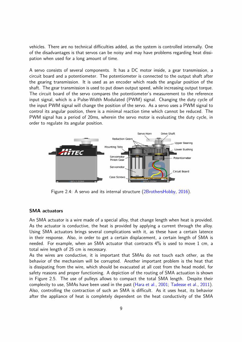
vehicles. There are no technical difficulties added, as the system is controlled internally. Oneof the disadvantages is that servos can be noisy and may have problems regarding heat dissi-pation when used for a long amount of time.
A servo consists of several components. It has a DC motor inside, a gear transmission, acircuit board and a potentiometer. The potentiometer is connected to the output shaft afterthe gearing transmission. It is used as an encoder which reads the angular position of theshaft. The gear transmission is used to put down output speed, while increasing output torque.The circuit board of the servo compares the potentiometer’s measurement to the referenceinput signal, which is a Pulse-Width Modulated (PWM) signal. Changing the duty cycle ofthe input PWM signal will change the position of the servo. As a servo uses a PWM signal tocontrol its angular position, there is a minimal reaction time which cannot be reduced. ThePWM signal has a period of 20ms, wherein the servo motor is evaluating the duty cycle, inorder to regulate its angular position.
Figure 2.4: A servo and its internal structure (2BrothersHobby, 2016).
SMA actuators
An SMA actuator is a wire made of a special alloy, that change length when heat is provided.As the actuator is conductive, the heat is provided by applying a current through the alloy.Using SMA actuators brings several complications with it, as these have a certain latencein their response. Also, in order to get a certain displacement, a certain length of SMA isneeded. For example, when an SMA actuator that contracts 4% is used to move 1 cm, atotal wire length of 25 cm is necessary.As the wires are conductive, it is important that SMAs do not touch each other, as thebehavior of the mechanism will be corrupted. Another important problem is the heat thatis dissipating from the wire, which should be evacuated at all cost from the head model, forsafety reasons and proper functioning. A depiction of the routing of SMA actuation is shownin Figure 2.5. The use of pulleys allows to compact the total SMA length. Despite theircomplexity to use, SMAs have been used in the past (Hara et al., 2001; Tadesse et al., 2011).Also, controlling the contraction of such an SMA is difficult. As it uses heat, its behaviorafter the appliance of heat is completely dependent on the heat conductivity of the SMA
9

Figure 2.5: The routing of SMAs in an animatronic baby head, using pulleys (Tadesse et al.,2011).
itself, limiting the speed at which it can be actioned. SMAs are often cooled with a built-infan to limit this problem.
Pneumatic actuators
Pneumatic actuators are also used regarding the actuation of animatronic heads, under severalforms. The most common use of pneumatic actuation uses McKibben actuators. A McKibbenactuator is shown in Figure 2.6.
McKibben actuators consist of an internal bladder surrounded by a braided mesh shell.
Figure 2.6: The McKibben muscle, a pneumatic actuator that shortens when pressure isapplied. (T. Hashimoto et al., 2006)
On one side, there is a canal leading to a controlled pressure source. The other side of thebladder is closed. When pressure is applied, the actuator shrinks in length and thickens inwidth, thus acting as a muscle (as shown in Figure 2.6). The face robot Saya, whose internal
10

structure is shown in Figure 2.7, uses McKibben actuators for facial expressions. The blackcomponents are the McKibben actuators.
Figure 2.7: The internal structure of Saya (T. Hashimoto et al., 2006). The black componentsare McKibben muscles, used to pull strings, attached to the skin of Saya.
An other example of pneumatic actuation is an ACDIS (Hara & Endo, 2000), which standsfor ACtuator including DIStance measurement. Such an ACDIS is shown in Figure 2.8. Itis a pneumatic actuator which is equipped with a double-action piston, along with an LEDand a photo transistor. The LED and photo transistor are used to control the position ofthe double-action piston, which is moved using a source of pressurised air. It is not oftenused. The main problem of using such an apparatus is that the dynamic behavior of the
Figure 2.8: An ACDIS actuator, as used in (Hara & Endo, 2000).
actuator is dependent on the compressibility of air, which plays a significant role. Also, aswith all pneumatic actuators, a constant pressure source is needed in order to actuate thehead, which cannot be a built-in feature. A pressure source is not always available. For solvingthis problem, a compressor may be used. The main disadvantage is that it is a voluminouscomponent, which makes a lot of noise when pressurizing its air reservoir.
Overview actuation methods
Regarding the previous listing of actuators, one can see that using servos has many advan-tages regarding control techniques and modularity. Using pneumatics entails possible leakage
11

problems which are not easy to trace back. SMA actuators have an intrincic routing problemdue to their inherent working principle. On the other hand, servos are compact, are easilyreplacable and cheap depending on their quality and they have a relatively long lifecycle, com-pared to SMAs. The only disadvantage of using servos is the noise they can generate duringmovement.
2.4 Controlling a face robotOne of the main difficulties in expressing emotions or mimicing speech with an animatronichead, is closing the gap between the desired expression / mouth shape and the thereforeneeded actuator configuration.
Solutions for this issue do exist. For example, actuator configurations can be predicted byusing a Finite Element Method (FEM) model where emotions are experimentally reproducedand deformation are evaluated (Weiguo et al., 2004; Tadesse et al., 2011; Bickel et al., 2012;Baldrighi et al., 2014). The quality of this result greatly depends on the quality of the modeland how complete the head was modeled. This can easily be done when the head is builtout of rigid parts. However, modelling a humanoid1 head having a deformable skin is notstraightforward, as it is not simple to model a highly elastic, non-linear material.
An other solution exists in experimentally determining which configuration is needed for eachemotion or mouth shape (Hara & Endo, 2000; Jaeckel et al., 2008; Kobayashi et al., 2002;Hara et al., 2001). This approach is not optimal, as this is manually done. Realistic humanoidheads have a lot of actuators (as the humanoid Albert HUBO, (Oh et al., 2006), which has31 degrees of freedom in his head), which shows that this solution takes time and is tideous.
A different approach consists in measuring muscle activities on a human face expressing severalemotions and projecting these on the working range of the humanoid’s head (M. Hashimotoet al., 2006). In this research, muscle activities are measured for each facial muscle groupthat is implemented in the face robot. This is done when the subject contracts each facialmuscle as best as possible. The same measurements are repeated when the 6 basic emotionsare expressed. Then, the maximal displacement on the subject’s face is measured for thedifferent muscles. Next, the wire tension and displacements of the robotic head are measuredin order to define a concept of stiffness. The muscle activities for each expression are then firsttranslated towards displacements. Finally, those displacements are converted to wire tensionsthanks to the previously defined stiffness. This approach is valid in this case as the robotichead is a replica of the subject itself.
2.4.1 Control methods: overviewIt is clear that there does not exist a universal solution to this problem except the trial-and-error approach. The control methods that have been defined in this section, can all be
1A humanoid = An antropomorphic robot
12

represented with the same structural layout, as shown in Figure 2.9 as they all use the samebasic principle. A method is used to provide a prediction of the actuator configuration neededfor each emotion or mouth shape. This prediction is then applied and eventually, the resultsare manually modified in an iterative fashion to get convincing results. Before the iterativestep, the real head is never used.
DESIGNNo head available
Head available
"Getting a head"
METHODSETTINGS
PREDICTION
TRIAL AND ERROR
APPLY TO
HEAD
TUNE
PARAMETERS
"Finding possible parameters" "Iteration"
FINAL RESULT
REPEAT FOR DIFFERENT CASES
Figure 2.9: A structural graph showing the layout of the applied methods in literature
2.5 Text to robot, general outlineIn order to make a face robot mimic speech, several steps need to be taken. These steps areshown in Figure 2.10.
SENTENCE
AUDIO?
PHONEME
SEGMENTATION?
VISEME
SEGMENTATION
?ACTUATOR
POSITIONS
?MOUTH
Figure 2.10: The different steps up to the actuation of the mouth
The different forms of data in the process are:
• an audio file, a sentence, or any equivalent information form;
• a list of phonemes2 and an associated segmentation file containing timings;
• a list of visemes3 and an associated segmentation file containing timings;
• actuation parameters that will shape the mouth into the desired form;
• a final result matching the desired sentence in a fluent way.
Between every information type, there is a conversion that has to be done.2A phoneme is every basic unit of speech. A language can be represented with a sequence of phonemes.
Examples are p, b, m for the Dutch language.3A viseme is the visual equivalent of a phoneme.
13

2.5.1 From sentence or audio up to phoneme segmentationThe conversion starts with the translation of a sentence or an audio file to a phoneme seg-mentation file. A phoneme segmentation file is a file containing the timing of every phonemeneeded to produce the sentence or audio. This first step of conversion can be done with con-version software. An example of such a software is SPRAAK (Demuynck et al., 2008), whichis a software that can convert both data types to a segmentation file containing phonemes.
In order to conceptualize this conversion, a graphical representation is shown in Figure 2.11.An audio file is represented which has been segmented in phonemes, along with a segmenta-tion file that has been represented in the graph underneath. Each color is accompanied by anumber. Each pair of number and color corresponds with a phoneme. For example, the deeppurple (number 42) blocks represent an r, which occurs 4 times in this sequence. Anotherexample is the e, occuring 4 times as well in the sequence, which is represented by the darkorange (number 2) blocks. In the graph, those are the lowest blocks.
1500 2000 2500 3000 3500
Time [ms]
Ph
on
em
e
48
2
42 43
25
42
15
2
14
2
42
19
15
26
35
16
48
17
34
45
51
16
31 32
17
4543
34
26
41
2
42 4345
37
32
10
45
Versier de bereiding eventueel met snippers tomaat.
Figure 2.11: A segmented audio file, along with its segmentation file which has beengraphically represented underneath, which reads ’Versier de bereiding eventueel met snippers
tomaat’.
2.5.2 From phonemes up to visemesVisemes are a set of mouth patterns that represent the phonemes from before. These set ofvisemes are predefined and there are not as many visemes as phonemes. As some phonemeslike the plosive p and b have a similar shape, they can be represented by the same mouthshape (viseme). An example of a partial viseme set is shown in Figure 2.12a.
14

(a) Visemes, representing a, i, u, e and o.(Hara & Endo, 2000)
(b) A possible clustering for ChineseMandarin phonemes, (Qingmei et al., 2008)
In reality, when we speak, the sound as well as the mouth shape used for a certain phoneme isinfluenced by the prior and subsequent phonemes. This effect has been defined as coarticula-tion (Ohala, 1993). It is an inertial phenomenon that occurs as the human mouth is not ableto accelerate infinitely fast in order to form distinct shapes. Up to today, no known researchhas taken this effect into account when actuating a robotic mouth.
2.5.3 From visemes up to mouth shapesUp to today, the conversion step from viseme4 up to actuator configuration has always beendone manually for a reduced set of visemes (Hara & Endo, 2000; Qingmei et al., 2008; Lin,Cheng, et al., 2011), or has not been mentioned (Lin et al., 2013). This approach is onlyfeasible for a reduced set of mouth shapes. As there is a rich variety of phonemes for anylanguage, it is likely that many of those phonemes have visemes that closely resemble eachother. For example the p, b and m. Manual calibration would result in inevitable errors thatcompletely overrule the subtleties of the mouth patterns, which is why clustering is applied(Lin et al., 2013; Qingmei et al., 2008). That is, several phonemes are grouped together andrepresented by the same viseme. An example of clustering is shown in Figure 2.12b.
2.5.4 From actuator configurations to fluent speechUsing the segmentation file of phonemes and the conversion of those to actuator configura-tions, one is able to mimic speech in a choppy way. In order to get a more realistic result,a linear interpolation between the central points of the phoneme sequence is carried out(Qingmei et al., 2008).
4without taking coarticulation into consideration
15

16

Chapter 3
Design of the setup and the mouth
3.1 IntroductionThis chapter handles all the parts of designing a setup, which will be used to study thebehavior of a prototype mouth. This complete setup has been designed in order to prove thatthe approach that is proposed in this thesis to calibrate a robotic mouth works. The principlesof this approach are explained in Chapter 4.
3.1.1 Preliminary aspectsThe design of a mouth has a lot of aspects that have to be taken into account. Some majorquestions that have to be answered:
1. What actuation method will I use?
2. How much degrees of freedom do I need?
3. How are actuation and mouth connected?
In the literature (see Chapter 2) there are different actuation mechanisms available, allhave their advantages and flaws. Seen the advantages of servos and their compactness,servos will be used to actuate the robotic mouth. The questions listed above can be somehowredirected and more precise towards our problem:
1. What do I define as a mouth?
2. How do I fix a wire to the mouth?
3. How many degrees of freedom will I use?
4. Will I use the symmetry of the mouth in my advantage?
5. How many wires will I therefore use?
6. Where are these wires located and what is their direction?
17

(a) Back (b) Side (c) Front
Figure 3.1: The test setup that has been designed during this thesis.
3.2 The test setupIn order to solve those questions, a test setup has been designed (see Figure 3.1). Theapparatus uses 5 servo motors to actuate a mouth that is located in a frame, as can be seenin Figure 3.1c. This setup consists of several stages. From the back, a first stage can befound that consists of a rack full of servo motors. From this actuation stage, wires come outand are then pretensioned in the next stage. This stage can change the length of the cable toavoid slack. The next stage is a wireguiding step which guides the wires to the right place.It also fixes the passage of the wire in one spot. In the last stage, wires are guided directly tothe mouth through a frame having a set of holes. It is possible to change the direction of thewires in this stage. The wires are at last fed to the mouth where the connection is made witha basic knot. In this setup, there is no space to add a jaw. This is however not a problem asthis is not the focus of this thesis.
Using a test setup as this one has the advantage of being modular. Changes can be donerelatively fast and experiments can be carried out relatively easy. A camera mount has alsobeen added for this purpose.
3.3 Controlling the setup
3.3.1 Controlling the servo motorsIn order to control the servos, the choice has been made to control them directly from Matlabthrough a Arduino UNO board, as a support package is readily available for that. This meansthat it is possible to directly control all servos with a simple Matlab command. The powerdistribution board that feeds the servos is shown in Figure 3.2. On the distribution board, onecan notice the presence of a little chip in the center. This chip measures the current drawn
18

Figure 3.2: The distribution board for feeding the servos
by the servos all together and can be monitored. Doing so, if a blockage of a gear systemoccurs in any of the servos, the error is immediately seen and the power is shut down to avoidpossible damage.
3.3.2 Calibration of the servo motorsThe transmission arms connect the servo motors to the wires. These have been designedas such to take as less space as possible. Once these are mounted, a proper calibration isneeded. Servo motors are PWM controlled. With the support package, a value between 0and 1 has to be given which will be mapped between the smallest and biggest (predefined)pulse duration. The servos used have pulse widths between 700 and 2300 µs. Values havebeen found experimentally to control the servos precisely. They can be precisely controlledbetween [−22.5, 22.5]. This calibration is needed in order keep the servo motors in theirsafe working range. Doing so, a simplification is made as such that every servo can now becontrolled by demanding a simple reference angle.
3.4 Designing the mouth
3.4.1 Preliminary aspectsThe design of the mouth is based on a human mouth and thus has an antropomorphic shape.The reason for that is that humans are the only species on earth, capable of mimicing speech,where the mouth has a substantial effect on the understandability of the speaker. If one wantsto design a mouth that enhances the understandability of the robot speaking, it thus shouldhave an antropomorphic shape. Next to that, research (Sakamoto et al., 2014) has shownthat only the lips and surrounding area contribute to the speech intelligibility when having a
19

visual perception of the speaker. Taking this in to account, a mouth has been designed, ascan be seen in Figure 3.3. As one can see, the mouth has the characteristics of a humanmouth and constists only of lips.
(a) Side (b) Front
(c) Under
Figure 3.3: The mouth seen from different angles
3.4.2 DeformationsThe material that has been used for making the mouth is NinjaFlex. It is the market leadingflexible filament and it is thus possible to 3D print structures with it. However, it is notextremely stretchy. During a conversation, the mouth deforms, but doesn’t stretch much. Theonly moments when a change of lip circumference is noticable is during protrusion. Protrusionis the phenomena occuring when pouting lips, for example for a kiss, or when expressing thephoneme y (pronouncing as ’oe’ in Dutch, ’ou’ in French and ’you’ in English). In thecontext of this thesis, pictures of a speaker have been used from prior research (Mattheyseset al., 2011; Mattheyses, 2013). On those pictures, the shape of each phoneme of the Dutchlanguage are shown. Processing those pictures showed that the lip circumference stretchesof 23% maximally. This can be attained with Ninjaflex as it can withstand an elongation of660% according to the manufacturer NinjaTek. For doing so, an internal structure for the lipis needed that can easily deform in order to limit the forces needed.
Internal lip structure
Different planar structures have been studied on deformation. The best one that could befound is the hexagonal structure, as its deformation is more efficient than other structures.Other structures that were tested are shown in Figure 3.4.A hexagonal structure can deform theoretically in two ways, as shown in Figure 3.5. Bytheoretically, it is meant without any micro-elongation, only looking at a structure consistingof rigid rods. When we look at the picture, it is clear that the orientation of the hexagon is
20

(a) A spring structurehaving a ’zigzag’ shapedunity cell
(b) A spring structurehaving a ’hourglass’shaped unity cell
Figure 3.4: Different planar structures that were tested for deformations
important. The first orientation give a poor result: an extension in longitudinal direction ofaround 15% and a transverse compression of −50%. The second orientation gives a muchbetter result: an extension up to 50% and a compression of −100%. This compression isalso seen with a real lip. As the lips are stretched, the lips become thinner, which is whatthis internal structure allows. In reality, a deformation solely on bending cannot be attendedwithout any stretching, since there is a bending resistance. This bending resistance is definedas follows:
Rbending = EI
L(3.1)
with
• E, the Young modulus;
• I, the area moment of inertia;
• L, the characteristic length of the hexagon.
It is clear that in order to approach the theoretical limit of 50% elongation, I has to be aslow as possible, meaning that the cross-section of the beam has to be as small as possible,while its length has to be as high as possible. The boundaries of this approach are entirelyfixed by the limits of the material and of the 3D printer. For example, the smallest thicknessthat can be attained is 400µm. The height of a hexagon beam is entirely fixed by the locallip depth.
Another aspect that has to be taken into account is that the lip cannot be a completelyclosed shell. If this is the case, unnatural warping of the lips will occur. Due to this reason,the lips are left open on top, so that no warping occurs. Taking this into consideration givesthe following result as shown in Figure 3.6. The hexagonal structure can be clearly seen.
The internal hexagonal structure has been oriented as such that the deformation of thelips will act as a real lip would behave. That is by looking longer and thinner. Having thehexagonal structure rotated by 30 would not allow that much deformation along the lipcircumference, which is now possible.
21

+15%
-50%
+50%
-100%
Figure 3.5: The two possible ways to stretch a hexagonal structure.
(a) Side
(b) Under
(c) Under
Figure 3.6: The open mouth with a hexagon internal structure, seen from different angles
3.5 Fixation of the wires on the mouthThe connection and positioning of the wires has been established based on the muscularstructure around a human mouth (Putz & Pabst, 2009) which is represented in Figure E.1.Its construction is shown in Figure 3.7. As the built frame structure doesn’t allow the imple-mentation of a jaw, a push pull system has been constructed with two vertical wires that pullin an antagonistical way. Those two wires represent the effect of the jaw and are actuatedwith one servo only. As can be seen, only the effect of linear muscles have been taken intoaccount. With this setup, only a pull effect can be applied on the mouth via the wires. Theeffect of this choice will be shown in chapter 7.
As seen in Figure E.1 in Appendix E, there are several facial muscles that need to be taken
22

into account. every linear muscle (all but the musculus orbicularis oris, musculus masseterand musculus pterygoideus lateralis) are connected to the musculus orbicularis oris, whichsurrounds the lips. It is for this reason that the wires have been fixed as close to the borderof the lips as possible. The musculus masseter and the musculus pterygoideus lateralis arerespectively responsible for the closing of the jaw and protrusion. The latter one has not beenimplemented due to complexity, meaning that the effect of the musculus pterygoideus lateralisand the musculus orbicularis oris won’t be seen: protrusion.
In the designed frame, it is possible to change the direction of the wires as supplementaryholes are foreseen.
Figure 3.7: The pose of the wires actuating the flexible mouth. These represent only linearmuscles. The represented muscles are shown in Figure E.1 in Appendix E.
23

24

Chapter 4
Principle of the method
4.1 IntroductionIn this chapter, a new approach will be proposed that allows to actuate any mouth in afluent way so that it mimics speech, whatever the actuation method behind the mouth andits behavior. In short, the method projects the robots mouth onto a standardised mouth andmoves it in such a way that the difference between the two is minimized. Doing this for everybasic unit of speech i.e.: for every phoneme, one is able to actuate the robots mouth so thatit is able to mimic any speech. This method has been applied to the robotic mouth that hasbeen designed for this thesis. The results are shown in Chapter 7.
4.2 General outlineLet us first recall the general flowchart that has been presented in the literature review 2 ofhow each approach in the literature handles the calibration of a face robot. The flowchart isshown in Figure 4.1 In here, it is shown that every previous approach but the trial-and-error
DESIGNNo head available
Head available
"Getting a head"
METHODSETTINGS
PREDICTION
TRIAL AND ERROR
APPLY TO
HEAD
TUNE
PARAMETERS
"Finding possible parameters" "Iteration"
FINAL RESULT
REPEAT FOR DIFFERENT CASES
Figure 4.1: A structural graph showing the layout of the applied methods in literature 2.
method did not use the real head when predicting actuator configurations, so the in the endfinal adjustments have to be carried out.
25

In Figure 4.2, a flowchart is shown of how this thesis proposes to approach the problem.There is a main difference between the two flowcharts. In the new approach that this thesis
DESIGNNo head available
Head available
"Getting a head"
EVALUATE
HEAD
TUNE
PARAMETERS
"Finding possible parameters"
FINAL RESULT
REPEAT FOR DIFFERENT CASES
APPLY TO
HEAD
Figure 4.2: A structural graph showing the layout of the new approach proposed in this thesis.
proposes, the actual face robot will be used during the calibration itself.The conversion steps of the new approach are shown in Figure 4.3:
SENTENCE
AUDIO?
PHONEME
SEGMENTATION?
VISEME
SEGMENTATION
?MOUTH
POSITIONS
?SERVO
POSITIONS
?MOUTH
ACTUATION
Figure 4.3: The different steps up to the actuation of the mouth
The different forms of data in the process are:
• an audio file, a sentence, or any equivalent information form;
• a list of phonemes1 and an associated segmentation file containing timings;
• a list of visemes2 and an associated segmentation file containing timings;
• a set of mouth coordinates, related to previous visemes: The MOUTH POSITIONS;
• actuation parameters that will shape the mouth in question to the desired form;
• a final result matching the desired sentence in a fluent way.
Compared to the forms of data that were shown previously in the literature review (inSection 2.5), there is a difference: between the viseme segmentation and the actual servopositions, there is an extra block: MOUTH POSITIONS. This concept will be explained inSection 4.5. Between every information type, is a conversion that has to be done.
1A phoneme is every basic unit of speech. A language can be represented with a sequence of phonemes.2A viseme is the visual equivalent of a phoneme.
26

4.3 From sentence or audio up to phoneme segmenta-tion
The conversion starts with the translation from a sentence or an audio file to a phoneme seg-mentation file. A phoneme segmentation file is a file containing the timing of every phoneme3
needed to produce the sentence or audio. This first step of conversion can be done withconversion software. An example of such a software is SPRAAK (Demuynck et al., 2008),which is a software that can convert both to a segmentation file with phonemes.
I have had the ability to use audio files that were already converted to phoneme segmenta-tion files. This data is part of previous research (Mattheyses et al., 2011; Mattheyses, 2013).Since the phoneme segmentation files are already available and that this conversion is out ofthe scope of this thesis, this process won’t be detailed. A list of the sentences that are readilyavailable and converted are shown in Table C.1.
In Figure 2.11 on page 14, one of these audio files has been shown, which has beensegmented in phonemes, along with that segmentation file that has been represented in thegraph underneath. Each number corresponds with a phoneme. The corresponding phonemesare listed in Appendix A. The list of phonemes is complete and can represent the Dutchlanguage completely. It is based on the FONILEX notation (Mertens & Vercammen, 1997),which contains the phonetic transcription of the most frequent word forms of Dutch as spokenin Flanders.
4.4 From phonemes up to visemesBefore being able to convert phonemes to visemes4, it is important to clearly define theviseme set. A viseme, being a visual representation of a phoneme, doesn’t have a one onone relationship. Several phonemes, like the plosive p and b, do have a similar shape. Thereare thus not as many visemes as phonemes. The number of visemes can also be more thanthe number of phonemes, as several phonemes can be mimiced differently. This is due toan inertial effect better known as coarticulation. This phenomenon is what one can remarkwhen uttering different words having the same phonemes. Visemes are altered dependingof the phonemes before and after the phoneme in question. In short, a certain phoneme isrepresented differently, depending on the precedent and subsequent phonemes.In order to ease the task of linking phonemes to visemes, the pictures that are used have beengenerated without the effect of coarticulation and are part of previous research (Mattheyses etal., 2011; Mattheyses, 2013). Doing so, every phoneme has a picture representing the mouthshape. Later on, the effect of coarticulation will be brought back in an algebraic way.
Examples of such viseme representing pictures are shown in Figure 4.4. The complete setcan be found in Appendix B.
3A phoneme is every basic unit of speech. A language can be represented with a sequence of phonemes.Examples are p, b, m for the Dutch language.
4A viseme is the visual equivalent of a phoneme.
27

Figure 4.4: A subset of viseme representing pictures. The complete set that has been usedin this thesis can be found in Appendix B.
4.5 From visemes up to mouth positionsMouth positions are a set of well-defined coordinates (further called POIs, short for Points OfInterest) that are able to represent the shape of the mouth in a compact way. Those haveto be generated from a viseme representing picture, as well from a picture of the mouth ofthe robot in question. The choice of those points will greatly influence the resulting mouthpositions and thus should be selected with care. In the case of this thesis, cable are actuatedthrough a set of servos that pull the mouth into shape. A good approach in this case con-sists in selecting the POIs as the fixation points where the cables are attached. This will befavorable in a upcoming step of the algorithm. However, several solutions are possible. Moreor less POIs can be added. The strength of the method depends on a good choice of POIs.In general, more POIs will result in a better shape. For simplicity, however, it is favorable tohave the POIs positioned on the fixation points.
Once the POIs are determined, these have to be normalised in such a way that POIsfrom a viseme can be compared to the POIs from the mouth of the robot in question.This is necessary, as there is always a scaling mismatch between both mouths. There isonly one way in doing that, which is done by only keeping shape information and removingscaling information. For doing this, a reference distance is needed, which is unbiased andnot influenced by any shape information. In the case of a mouth, the only reference distancefulfilling these conditions is the lip circumference. This property of the lip is only dependenton the scaling of the lip.
The next step consists in defining an appropriate reference frame. The most straightfor-ward choice, is a reference point which is not moving at all, so that representing movementbetween several configurations is simplified and clear. There is only one point which can beassumed as non moving, this is the top center point of the lip. This point is shown in Figure4.5 as well as the reference frame.
When defining the reference frame, it is assumed that the robotic mouth is shown correctly,that is with the lips straight and not tilted compared to the reference frame of the measuring
28

device (in this thesis, a webcam has been used). If this is the case and this cannot be reducedmanually, the measurements of the POI can be used to create a reference frame.In order to do so, the average of each POI is taken as to represent the center of the mouth.The vector formed by this center and the reference POI define the vertical direction, defininga complete reference frame which can be used.
Figure 4.5: The points of interest on a dummy mouth along with the definition of thereference frame of choice.
By now we are able to normalize each POI using the lip circumference, after expressingthem in the reference frame of choice.
4.6 From mouth positions up to actuator configurationsTaking the whole system into consideration for the actuation of the mouth can be complicated.Especially non-linearities have to be taken into account if the mouth deforms elastically, as isthe case for the mouth that has been designed (see Figure 3.3). What has to be done is finda way to link the behavior of the actuation and the resulting deformations as such, that onefinds the necessary configuration of the actuators in order to get the desired deformations.There are several solutions to do that. For example, one could:
1. Model the complete behavior of the setup in order to find a link between actuatorconfiguration and desired mouth position;
2. Create a database of different actuator configurations in order to look at which config-urations give desired mouth shapes;
3. Use a feedback algorithm to actuate the mouth.
Modeling the complete behavior of the setup
In order to model the complete behavior of the setup, every single component that has aneffect on the system needs to be modeled as well. The most complex part in this thesis is
29

the mouth itself as it deforms elastically. The mouth has a complex shape which has beendesigned as such to deform easily. Since it has been designed, CAD models are available.However, there is no information about the manufacturing quality of the mouth itself, whichcalls for assumptions. The mouth prototype has been 3D printed in a flexible material calledNinjaflex. Modeling elastomeric polymers can be done using FEM models but is not simpleas big deformations are desired which ensure non-linear elastic behavior.
Creating a database of actuator configurations
In this case, a method is needed to measure deformations quantitatively in a precise way.A solution could be using a webcam along with recognition software, as such that it coulddetermine the position of the mouth in a consistent way.
The method has one big advantage, which is that it omits any need to know the wholebehavior of the system in question, as it takes combinations. This method is robust and leadsto results. The price to pay is that the method is slow, tideous and cumbersome: First of all,all combinations have to be carried out and pictures have to be taken of the mouth. A lotof them won’t be used and are wasted time. Then, recognition software has to loop over allthose pictures, finding mouth shape and saving all information necessary. All the pictures thatwe won’t need are evaluated also and will be discarded in the next step. Afterwards, all mouthpositions are processed and a link is set between mouth shape and actuator configuration. Itis then possible to attribute configurations to all mouth positions who closely fit the referenceshapes.
Some questions that have to be asked are the following:
• How much combinations do I need?
• What do I define as ’close enough’?
• What if I am not satisfied with the results?
Those three questions are intertwined: The number of combination depends on how preciseyou want the result to be, which can be interpreted as what is defined as ’close enough’. Also,stating that you are not satisfied with the results means that the results are not close enoughto the reference, which shows that there are not enough combinations close to each other.This little thought experiment reveals that, even being robust, the database has a flaw, whichis that you have a contradiction. On the one hand, it is desired to get results close enough,thus needing many combinations, while you do not want many combinations as a lot of themare not used, but still need to be interpreted. These combinations that will not be used taketime, which is literally wasted. A partial solute could be to combine several combinations,close to the reference, to form a new set of parameters, which should give closer results. Thisincreases the resolution locally, without increasing the number of combinations drastically, asdid the method before. Still, it can be concluded that the method is complex and not optimal.
30

Use a feedback algorithm to actuate the mouth
The method proposed uses a feedback loop to ensure the closest result possible. Its perfor-mance is completely dependent on user defined control.
The concept is the following:
1. Set the actuators to a neutral position
2. Take a picture of the robotic mouth.
3. Recognize the POIs.
4. Load the POIs of a standard picture.
5. Make sure that the POIs are expressed in the correct reference frames.
6. Normalize all POIs with their respective lip circumference.
7. Compare both POIs in a non-dimensional space.
8. Vectorize the differences of respective POIs.
9. Project these vectors in a well-defined way on the actuators line of action.
10. Use the signed results as a feedback to the actuation.
11. Repeat from step 2 until convergence.
In this thesis, as the POIs are equal to the actuation points, the projection is easy to carryout.
ref pictureref POIs ref POIs*
POIs* POIs picture
POIs*mouthsystemPIK
webcamM1M2
M1 M2
ref picture
Figure 4.6: The feedback loop of the implemented algorithm. M1 extracts POI data frompictures, while M2 processes those POIs and expresses them in the correct reference frame.
Those steps can be compacted to a control loop as shown in Figure 4.6. In here, thereference picture is compared to the actual mouth position using POIs. The difference isconverted into useful values that are then added to the actual angles that are requested.This kind of control is an integral control.
31

Evaluation of the database approach
Preliminary tests have been carried out for the database algorithm. Having 5 servomotors tocontrol, with a working range of 40, creating a database with a resolution of 5 would take3 hours to:
• Move servos to the desired position;
• Take a picture;
• Recognize POIs;
• Store angles and POI data.
as the time needed to create the complete data set increases as follows:
Ttotal = Tmean
N∏1
ni
δi
(4.1)
where:
• Tmean is the mean time needed for 1 move only, including all previous steps;
• N is the total number of actuation units;
• ni is the total working range of actuation unit i;
• δi is the resolution used for unit i.
In this case, N=5, ni = 40, δi = 5, gives a total of 59049 combinations. Having Tmean = 3,running the complete database would take 49 hours. In order to put things into context, Table4.1 shows the time needed for a different amount of servos.
Table 4.1: The time needed to create a database in function of the number of servos.In this case, there are 9 combinations to do for each servo.
n time number of combinations5 49 HOURS 590494 5.5 HOURS 65613 36 MINUTES 7292 4 MINUTES 811 27 SECONDS 9
It is clear that this solution, while being robust, is not feasible at all for precision and ahigh number of actuators.
32

Evaluation of the feedback approach
Regarding the feedback algorithm, tests concluded that the method is robust, but dependson controller gain: This one and only gain is the link between the signed projection of everyPOI error on a line of action of the actuation and the change of angle that is requested ofthe actuators.Changing the gain is influencing the response time of the system, as well as the sensitivity ofthe system: small errors have a bigger influence when the control gain is important. Thereis inherently some damping in the system due to friction and others, which keeps the systemstable up to some extent. Even if this system discrete, it is perfectly possible to make itinstable, which should be avoided at all cost.
The system is assumed to be made out of multiple SISO (Single Input Single Output) systems,while in reality it is a MIMO (Multiple Input Multiple Output) system due to coupling termsgenerated by the deformable mouth. Every POI has been attributed to a single actuator,thus assuming that and actuator j won’t influence a POI i, for i 6= j. Due to the inherentconstruction of the mouth, this influence is not negligible and most importantly in the abilityto converge as will be shown next.
High gains result in clearly visible coupled oscillatory phenomena, prohibiting the methodto converge. Its working principle is simple to understand:A small error is amplified considerably by a high gain, thus deforming the mouth shapeconsiderably. This action alters the position of an other POI (or more), which on his turnrepeats the complete process, resulting in oscillatory movement of the reference angles. Anexample is shown in Figure 4.7
More than that, there is a treshold present in the servo motors: there is a minimalchange of angle needed to affect the position of the servo. This effect amplifies the coupledoscillatory phenomena in such a way that the amplitude of those waves are non-negligible.Their frequency and amplitude mainly depend on the control gain previously defined. Thewaves shown in Figure 4.7 are not ’classic’ system oscillations, which can be seen in the factthat every shock or change in the different actuators happen simultaneously, as well as thesewaves keep repeating and are not damping out.
Another discontinuity that has to be taken into account is that of the POI detectionsoftware. Due to the pixelized image, POI positions are discrete and have integer coordinatesbefore normalizing. This effect introduces microshocks in the system which can further preventthe convergence of the system.
Luckily, this undesired phenoma can be attenuated by using a variable gain technique.Several techniques can give satisfying results. Some of them are shown in Figure 4.8
These techniques vary the control gain in function of the total distance error between allrespective POIs. All are reducing the control gain for smaller error, thus having a stabilizingeffect on the system dynamics. The most basic technique uses a linear changing gain betweenKconstant and 0.
33

100 200 300 400 500 600 700 800 900 1000
iterations
-20
-15
-10
-5
0
5
10
15
20
θ [
°]
∆θ1
∆θ2
∆θ3
∆θ5
∆θ6
Figure 4.7: The oscillations appearing due to coupling of actuators.
K(d)
ddstartd
lim
Kconstant
Figure 4.8: Variable gain techniques compared to fixed gain control.
The convergence performance depends greatly on the similarity between the reference androbotic mouths. When big constructional differences exist, there will be a remaining errordlim once the convergence is complete. This dlim cannot be eliminated. This value is mostlydepending on the disimilitude of both mouths, but also on the quality of the actuator fixation.If both mouths are similar and POIs are similarly positioned, dlim will be small, while havingtwo different mouths will give a remaining dlim which is not negligible. This will result in ahigh control gain around convergence, which will still induce coupled oscillations.
34

A solution for this problem could be to shift the gain between 0 and dstart up to dlim anddstart, which will greatly reduce this problem. The biggest issue in this case is that dlim is aninitially unknown quantity. Since it is mostly dependent on the disimilitude (which is relative)between both mouths, and not on the mouth shapes (which are absolute), dlim will be a rel-atively constant value for any mouth configuration. This property could be further exploitedto predict the value of dlim, in order to fasten the convergence of upcoming calibrations forthe next reference mouth shapes. Other variable gain strategies are also shown in Figure 4.8which further exploit the knowledge of dlim.
In order to emphasize the power of a variable gain strategy, the result of using a linear gainis shown in Figure 4.9. Note that the oscillations are remarquably smaller but still present,since dlim is still non-negligible. In Figure 4.10, a linear gain strategy has been used, whichuses a prediction of δlim to stabilize. As can be seen the convergence is assured. However, itsconverging speed is lower, compared to the fixed gain strategy shown in Figure 4.7. There,pseudo convergence was attained after 45 iterations, whereas the variable gain strategies needrespectively 60 and 120 iterations. These are thus 1.3 and 2.0 times slower. In order toaccount for this loss, more complex strategies can be used as shown in Figure 4.8.
50 100 150 200 250
iterations
-20
-15
-10
-5
0
5
10
15
20
θ [
°]
∆θ1
∆θ2
∆θ3
∆θ5
∆θ6
Figure 4.9: Near convergence using a linear varying gain control strategy. The nearconvergence is due to the dissimilitude between both mouths that is non negligible.
Possible methods to assess dlim
As may have been noticed, it is impossible to know dlim beforehand in order to use a morecomplex method using the value of dlim. A possible solution for this problem consists in usingthe dlim of the previous picture and so forth. In order to start, the first picture could be
35

50 100 150 200 250 300
iterations
-20
-15
-10
-5
0
5
10
15
20
θ [
°]
∆θ1
∆θ2
∆θ3
∆θ5
∆θ6
Figure 4.10: The coupled oscillatory phenomena are gone thanks to a variable gain strategy.A linear gain using dlim as origin has been used.
processed omitting the use of dlim and will be refined afterwards using the dlim of the lastpicture. A question that can be asked is if this iterative change of dlim is really needed asit shouldn’t change much of value. Next to that, the calibration of the face robot should bedone only once.
36

Chapter 5
Calibration Software
5.1 IntroductionIn order to put the method into practice, software has been created in Matlab. In thischapter, there will be a brief discussion about how the software has been implemented alongwith some results. First, the recognition software used for converting standard mouth picturesinto standard POIs (Points of Interest) is detailed. Secondly, the software used for mappingthe servo positions for each standard picture, will be briefly explained.
5.2 Recognition of the POIs for reference mouthsThe first important script that has been written is a shape recognition package that allows oneto import pictures of mouths and extract mouth shapes. In Figure 5.1, some mouth picturesare shown, that have been used to extract mouth shapes. These pictures are part of previousresearch (Mattheyses et al., 2011; Mattheyses, 2013). The complete set of them is shown inAppendix B.
Figure 5.1: Some pictures that are used to extract mouth shapes.
These figures have been processed by a Matlab script in order to extract the mouth shape ofit. An example of this process is shown in Figure 5.2.
37

First the original image is cropped in order to contain only the mouth. Next, a transfor-mation is applied in order to remove artificially any effect of shadows. Then, several colormapping are used to increase the difference between the lips and the skin of the subject (upperleft image). Then, the K means algorithm is applied which groups all pixels that resembleeach other together in a predefined number of groups. The result is shown in the lower leftimage. At last, a new grouping is carried out, separating skin from the rest of the image. Thepercepted skin is shown in white, whereas the lips are shown in black. The result can be seenin the upper left image.
In order to process this image, the whole dark area is analyzed such as to give a contour.This contour has the shape of the lips we seek. Finally, the POIs that will compact theshape data of the mouth are found by well-defined mathematical conditions that process thecomplete lip shape. The result is shown in the lower right image.
Applying this strategy for each of the 55 previously defined reference mouths gives us away to translate rach picture to a set of well-defined POIs.
Figure 5.2: The mouth shape recognition script, recognizing the mouth shape (lower right)using a set of color mapping (right up), K means clustering (left under) and grouping strategies(left under) in order to find the lip shape. The POIs are found using well defined mathematicalconditions.
5.3 Recognition of the POIs for the robotic mouth
In this thesis, a webcam has been used to take pictures of the robotic mouth. The images areanalysed in the same fashion as the reference mouth: Distinct POIs are immediately foundafter pre-processing the images.
38

5.4 Mapping servo positions with reference shapesIn order to map the previously found POIs of the reference mouth shapes with the POIs ofthe robotic mouth, software has been implemented that incorporates the principles that werepreviously defined in Chapter 4. The results are shown in Figure 5.3.
Figure 5.3: The interface of the calibration script that was used throughout this thesis. Theinterface gives a clear overview of each step during the calibration.
In this picture, several subfigures are shown. The interface gives an Overview of the Setupin order to show if the fixation points to the frame are well-defined. This is important as thesedefine the lines of action of each controlled point.
What is also shown a graphical representation of where the POIs of the reference mouthsare located (Close up reference) as well as those of the robotic mouth (Close up mouth).Those two sets are then expressed in the correct reference frame and normalised using thelip circumference (as was explained previously in Section 4.5). Those transformation are thenused to combine both results in a Dimensionless Space. In this subfigure, the two mouths arerepresented with their POIs and the line of action of each wire is shown.
The differences of corresponding POIs are vectorized (and shown as green vectors) and pro-jected onto the line of action of each wire. These projections are now signed error measure-ments which can be used to control the reference position of each servo. These errors areshown in error Points Of Interest, for each pair of POIs.
Remark that this result (shown as a red filled area) is symmetric. This is due to the factthat the mouth is actuated symmetrically. This means that several wires are actuated by thesame servo. There are in total 9 controllable POIs (along with 1 reference POI that does notmove). For those 9 POIs, there are 10 wires, but only 5 servos.
These results are used in concatenated and gained in order to have a meaningfull reference
39

change for each servo, which is shown in ∆θ Servo.
After each iteration, these increments are added to the references of each servo, which arethen applied for the next iteration. This complete process is repeated until convergence en-sues, for each of the 55 pictures. Doing so, the calibration of the robotic mouth is complete.The results are discussed in Chapter 7, whereas the configurations themselve are shown inAppendix D.
40

Chapter 6
From actuator configurations to actualspeech
In the Chapter 4, a method has been given that allows to find an actuator configuration foreach mouth standard. In this section, it will be shown how the mouth can be actuated insuch a way that it mimics speech in a fluent way.
6.1 Back to basicsRecalling the general outline of the method (which is shown in Figure 4.3), one could thinkthat having a segmentation file and all actuator configurations for each phoneme, the mouthis only one step away from mimicking speech. This is not the case. There are still someaspects that need to be taken into consideration. In order to make this clear, Figure 6.1shows what applying a unprocessed segmentation file would give as result:
Sending this data straight to the actuators would give a choppy result, which has to beavoided at all cost. The main goal of this last conversion step is to generate a fluent result.For doing so, different steps will be taken in order to get a convincing result:
• The segmentation will be linearly interpolated in the mid of each segmentation;
• On top of the previous interpolation, parabolic blends are added, representing th effectof coarticulation;
• A clustering of the phonemes will be performed, representing each cluster with a specificrepresentative phoneme;
• Attributing to each phoneme a level of importance, thus excluding those that do notcontribute to the understanding of the speech.
The clustering of phonemes and the concept of level of importance will be explained respec-tively in Sections 6.1.2 and 6.1.3.
41

1000 2000 3000 4000 5000 6000 7000
Time [ms]
Ph
on
em
e
15
42
25
15
10
23
2
48
36
42
2
45
14
2
23
26
34
48
11
34
15
2
31
17
43
2
49
17
42
45
26
30
37
41
50
2
14
17
31
45
32
17
45
15
2
32
16 15
2
15 16
31
26
35
9
15
11
45
15
2
30
52
4243
52
43
49
11
43
23
2
11
34
52
31
16
42
45
15
36
42
2
34
23
2
14
42
17
30
10
34
14
2
31
11
35
4345
17
31
26
35
Drie dagen voor het begin van de lessen werd ik opgebeld met de mededeling dat de cursus was geannuleerd door een gebrek aan belangstelling.
Figure 6.1: A segmented audio file, along with it segmentation file graphically representedunderneath, which reads ’Drie dagen voor het begin van de lessen werd ik opgebeld met de
mededeling dat de cursus was geannuleerd door een gebrek aan belangstelling’.
6.1.1 Linear interpolation with parabolic blendsAs shown in the litterature review (Chapter 2), only linear interpolation has been used toproduce continous speech. In this study, a linear interpolation is used with parabolic blends.The parabolic blends are used to account for the effect of coarticulation, which is an inertialeffect that shows the acceleration limits of a real human mouth. Parabolic blends have aconstant acceleration. They are thus a good representation of coarticulation.The implementation that has been used in this thesis is based on literature (Craig, 2004) anduses only one parameter to determine the shape of the parabolic blends. This parameter isthe constant acceleration in the blend, θmax.The maximal acceleration of the actuators can be used as a guideline to fix the value of θmax,if this information is available. If so, this could be used to asses the ability of the servos tokeep up with the speech. If an error occurs during the interpolation with θmax = θservos, thenthis means that the selected actuators are not capable to keep up the pace.There are several solutions for that:
• Use quicker actuators;
• Slow down the speech, while keeping the pitch constant (possible up to -20%);
• Removing phonemes might as well help;
• Replace linear interpolation with parabolic blends by a moving averaging window. Thiswill help to some extent.
42

Quicker actuators cost more and are not the best solution as there are many tricks that canbe used to get convincing results with slower actuators. For example, one could slow downthe speech. This can be done, while keeping the pitch constant. If not, the speaker willget a lower voice, which has to be avoided. Solutions for this problem exist and there areseveral implementations available to slow down speech while maintaining a constant pitch.The function that has been used for this purpose has been implemented by (Ellis, 2002),which is an implementation of the Phase Vocoder algorithm (Flanagan & Golden, 1966).
6.1.2 Clustering phonemesClustering phonemes is used in a lot of applications. The main reason for using clusters is toavoid over-articulation, which would result in exaggerated mouth poses. A set of phonemesrepresenting the basic units of a language, often have a lot of similarities, regarding shapeand type. For example, the plosive1 p and b have a similar shape (as seen in Figure 6.2),although the location of the sound formation in the mouth is different.
p b
Figure 6.2: The similar visual representations of phonemes p and b
Clustering groups have been defined for Dutch in literature (van Son, 1994). This listinghas been completed with extra notations that are typical for the YAPA notation, as thisnotation has been used for the segmentation files of (Mattheyses et al., 2011; Mattheyses,2013). The YAPA notation is a notation that has been defined as such to write down phonemeswith ASCII characters, in order to implement computer algorithms in a simpler way. The listof clusters is shown in Table 6.1. 11 groups have been defined and each of them is representedby a specific viseme. For example, the f, v and w have been clustered and will be representedby the viseme for w.
6.1.3 Phoneme importance levelsDuring a conversation, people may find the necessity to enhance understandability of thecounter player. They can improve that by lip reading the speaker. During lip reading, one
1 A plosive is a consonant in which the vocal tract is blocked so that all airflow ceases.Examples of plosives are k, g, p, t, b and d.
43

Table 6.1: The clustering of phonemes that has been used, is based on (van Son, 1994) andhas been augmented with phonemes (which are underlined) that are specific for the YAPA
notation.
cluster_number members representative1 b, p, m, mcap b2 f, v, w w3 s, scap, z, zcap s4 d, j, jcap, l, n, t t5 g, gcap, h, k, ncap, r, x k6 @, E∼, e, emarg, i, icap, emargj, ecap, ieuw, eeuw, aj e7 A∼, a, acap a8 @marg, O∼, Y∼, ocap, u, y, ycap, oj, oei, uw ycap9 ampers, o, omarg o10 9, @marg9, omargw @marg911 _ _
seeks for characteristic visemes which indicate possible phonemes (for example as in Figure6.2), that can be grouped to possible words. During this decryption, some phonemes aremore valuable for deciphering mouth shapes to speech. The reason for that is because ofcoarticulation. Some phonemes are considerably more coarticulated than others, makingthem invisible. Other phonemes are kept intact, which will be called protected. Off coursethere is a transition between these two groups, where phonemes suffer less deformation butwhich is not negligible. Those phonemes are normal. In Appendix C, a list of phonemes hasbeen enriched with levels of importance. In this list, invisible phonemes are tagged as INV,normal phonemes as MID whereas protected phonemes are named PTD. The proportion ofeach group is shown in Table 6.2.
Table 6.2: The presence rate of each phoneme group
PTD MID INVpresence rate [%] 34.5 47.3 18.2
In order to increase the understandability of the robotic mouth, invisible phonemes will beleft out intentionally, giving more ’time’ for protected phonemes, enhancing the speech quality.This is not real time that is given but more place (in the time domain) to smooth out withcoarticulation. Besides, possible calibration errors on invisible phonemes will not be shownwhich is an other advantage. The effect of hiding the invisible phonemes is shown in Figure6.3. In the graph above, linear interpolation is applied, while in the lower graph, parabolicblends are added, showing that hiding invisible phonemes gives more ’time’ for coarticulation.The mean distance between points in the interpolations is longer, while the position of thephonemes remains unchanged.
44

time [s]0
an
gle
[°
]
time [s]0
an
gle
[°
]
Figure 6.3: The influence of hiding invisible phonemes in the segmentation file. In the graphabove, linear interpolation is applied, while in the lower graph, parabolic blends are added,
showing that hiding invisible phonemes gives more ’time’ for coarticulation.
45

46

Chapter 7
Tests and results on the setup
7.1 IntroductionIn this Chapter, the results of the tests that have been carried out on the setup are out areshown. First, the calibration results are shown compared to the reference pictures.
7.2 Calibration of the test setupOne calibration of the setup has been carried out. The calibration has been done for 55 ref-erence mouth shapes, that were previously defined by (Mattheyses et al., 2011; Mattheyses,2013). These 55 reference mouth shapes represent each of the 55 phonemes defined by theFONILEX manual (Mertens & Vercammen, 1997). As explained previously in Section 6.1.2,a clustering has been carried out, meaning that several phonemes are visually represented bythe same picture. Since 55 pictures are a lot, only the results for each cluster are shown.
In Figures 7.1 and 7.2, the mouths representing each cluster are shown, along with thereference picture. There has been no tuning of the parameters after the calibration has beencarried out. These are raw results. The angular configuration of each servo has been listedfor each of the 55 pictures in Appendix ??.
47

Figure 7.1: The calibration results compared with the reference mouths for the first 5 out of11 clusters. The pictures represent each cluster and correspond respectively with b,w,s,t and
k.
Figure 7.2: The calibration results compared with the reference mouths for the last 6 out of11 clusters. The pictures represent each cluster and correspond respectively with e,a,ycap,o,
@marg9 and _.
Figures 7.1 and 7.2 prove that the new method works. It is possible to calibrate the mouthsetup with several reference pictures, which gives very convincing results.There are however several differences that can be seen in the results:
1. Protrusion cannot be shown, which means that y (pronounced as ’oe’ in Dutch and ’u’in English), will have a biased result. This can be seen in Figure 7.2 in the third andfourth picture from the left. This is due to the fact that the lip length of the mouthsetup cannot be controlled, since the M. orbicularis oris has not been implemented.This error is not due to the method.
2. No push-pull cables were used. Due to this, there is a possible saturation that hasoccured in the control, which can be seen in the angular servo settings in appendix??. The results are represented graphically in Figure 7.3 Some values of the servos areconsistently on the limits of each servo (that have been set to −20 and 20 for safetyreasons). This is due to two reasons: on the one hand, pushing is not possible, so thatthe controlled system will try to push further until angle saturation occurs. This effectcan be seen visually if there is slack in the cables. On the other hand, this saturation
48

could also occur if the required angular positions are outside the working range of thesystem, meaning that the system is badly designed. It has been verified that eachsaturating servo had slack in the cable.
3. The POIs were defined on the outer side of the lips. Due to this choice, it is possible tohave a mouth that is nearly closed, while the reference is completely closed. In order tosolve this problem, POIs could be defined on the inner part of the lips, in order to makesure that the lips will not be apart when they are supposed to be closed. The partinglevel of the lips when completely closing is desired depends on the dissimilitude of bothmouths regarding lip thickness.
0 10 20 30 40 50 60
-20
-15
-10
-5
0
5
10
15
20
θ1
θ2
θ3
θ5
θ6
Figure 7.3: The calibration results, graphically represented for each of the 55 mouth shapes.Some values of the servos are consistently on the limits of each servo (that have been set to−20 and 20 for safety reasons). This is due to two reasons: on the one hand, pushing isnot possible, so that the controlled system will try to push further until angle saturationoccurs. This effect can be seen visually if there is slack in the cables. On the other hand,this saturation could also occur if the required angular positions are outside the workingrange of the system, meaning that the system is badly designed. It has been verified that
each saturating servo had slack in the cable during saturation.
49

50

Chapter 8
Conclusions
8.1 Fullfilment of the goalsThe results with the robotic mouth that have been detailed in Chapter 7 show promisingresults. The goals of this thesis that were previously defined were:
The goal of this thesis is to present a new approach that could be used to calibraterobotic mouths in order to properly mimic speech.
In order to validate this concept, a test setup has to be designed, consisting ofa robotic mouth, which will be calibrated with the new approach.
The quality of the approach will be assested by the use of a lip-synchronisationmodule, which will allow to mimic speech.
The new approach should be able to:
1. Calibrate the robotic mouth by omitting the complete knowledge of the robotichead;
2. Do this fully automatically;
3. allow an objective evaluation about the configuration quality of the DOFs thatare implemented in the mouth.
In this thesis, a test setup has been proposed, having a robotic mouth. A new approachhas been proposed to calibrate the robotic mouth automatically, without any knowledge ofthe complete system. In Chapter 7, it has been shown that the results given by the methodallow to evaluate the configuration of degrees of freedom objectively. Also, these results haveshown that the calibration gives convincing results.
51

No text to speech module results have been shown. These results will be presented onthis thesis’ defence by showing several videos.
8.2 DiscussionThe method that has been proposed has used the projection of the robotic mouth onto pla-nar reference mouth shapes. However, the method is not constrained to the use of planarreferences. For example the use to 3D scanning adevices (as for example provided by Vixon,leader in this technology), can give 3D data of how an animatronic head would look like. Thesame can be done with reference data, coming from a real person that has been scanned aswell. The main difficulty here would be to shape these two data sets as such that they canbe compared. In other words, the main difficulty would be to project the two faces onto areference head that is standardised.This standardisation has been carried out as wel by using the lip circumference of the lips toallow a comparison between robotic mouth shapes and reference mouth shapes.
This means that the approach proposed in the thesis could be used to calibrate completeanimatronic heads, not only for mimicing speech, but also to express emotions.
8.3 Future workThe proposed approach is very general and has been implemented in order to calibrate ani-matronic mouths, using planar projections. Future research could be conducted on how thisapproach can be used to project complete faces to a standardised shape, in order to be tocompare complete face forms. In this context, it would be interesting to study the calibrationquality of this approach and to see if it can be used to control any animatronic head.
52

Appendices
53


Appendix A
List of all phonemes for Dutch
In this part of the appendix, one can find a list of all phonemes for the Dutch language.These are represented in Figure A.1. These are shown in different notations, YAPA-FONILEX-BROAD, YAPA-FONILEX-BROAD and IPA. Next to that, examples of use are shown, alongwith the level of importance of each phoneme, as defined in Section 6.1.3.The list of phonemes is complete and can represent the Dutch language completely. It isbased on the FONILEX notation (Mertens & Vercammen, 1997), which contains the phonetictranscription of the most frequent word forms of Dutch as spoken in Flanders.
55

N. YAPA-FONILEX-BROADYAPA-FONILEX-
BROADIPA Example LoI
1 9 9 ɥ intuïtief MID
2 @ @ Ə de MID
3 @marg @: œ freule, oeuvre MID
4 @marg9 @:9 œY huis MID
5 A~ A~ ƌ~ croissant MID
6 E~ E~ Ɛ~ vaccin MID
7 O~ O~ Ɔ~ congé MID
8 Y~ Y~ Y~ parfum MID
9 _ _ _ empty MID
10 a a ƌ naam PTD
11 acap A ɑ pat MID
12 aj aj draai PTD
13 ampers & Ø deur MID
14 b b b bak PTD
15 d d d dak INV
16 e e e veer PTD
17 ecap E Ɛ pet MID
18 emarg E: Ɛ crème, militair MID
19 emargj E:j ƐI fijn MID
20 ew ew sneeuw PTD
21 f f f fel PTD
22 g g g goal, zakdoek INV
23 gcap G Ɣ goed, zegen INV
24 h h h hand INV
25 i i i vier PTD
26 icap I I pit MID
27 iw iw nieuw MID
28 j j j ja INV
29 jcap J ɲ oranje, champagne INV
30 k k k kap INV
31 l l l land MID
32 m m m met PTD
33 mcap M ɱ kamfer, aanvalt PTD
34 n n n net INV
35 ncap N Ƞ bang MID
36 o o o voor PTD
37 ocap O Ɔ pot MID
38 oj oj mooi PTD
39 omarg O: Ɔ roze, zone MID
40 omargw O:w Ɔ Ʊ goud PTD
41 p p p pak PTD
42 r r r rand MID
43 s s s sein MID
44 scap S ʃ show, sjaal MID
45 t t t tak INV
46 u u u roer PTD
47 uj uj roei PTD
48 v v v vel PTD
49 w w w wit PTD
50 x x x toch INV
51 y y y vuur PTD
52 ycap Y Y put MID
53 yw yw duw PTD
54 z z z zijn MID
55 zcap Z Ʒ bagage MID
LoI = Level of Importance
Figure A.1: All the phonemes for the Dutch language in different notations, along withexamples of their use and their level of importance.
56

Appendix B
Complete viseme set
In this part of the appendix, a list is given were each phoneme is represented by a differentviseme, in Figure B.1. The effect of coarticulation has been iteratively removed by combiningdifferent appearances of the same phoneme. This is why in some pictures a second row ofteeth seems to appear. This data comes from (Mattheyses et al., 2011; Mattheyses, 2013).
57

Figure B.1: The visemes that are allocated to each phoneme for the Dutch language.
58

Appendix C
Default sentences
In this part of the appendix, a list is given with each of the default sentences available from(Mattheyses et al., 2011; Mattheyses, 2013), along with a translation to English.
59

Table C.1: Standard sentences in Dutch along with their translation in English
Number Language Sentence
NL Versier de bereiding eventueel met snippers tomaat.1 EN You can eventually finish the preparation with snippets of tomato.
NL In het verslag analyseer je wat er fout gegaan is.2 EN Analyze the mistakes in the report.
NL Er loopt nog steeds veel politie op straat en er rijden nog steeds wagens metveel militairen rond.
3 EN There are still a lot of policemen on the street and military trucks driving.
NL Drie dagen voor het begin van de lessen werd ik opgebeld met de mededelingdat de cursus was geannuleerd door een gebrek aan belangstelling.
4 EN I was called three days before the first lesson with the notification that thecourse was cancelled due to a lack of interest.
NL De groene partij moet daarbij een aantal harde noten kraken.5 EN The green party has to crack some tough nuts.
NL In het stuk is zijn favoriete vergelijking die van de mens als messentrekker.6 EN His favorite comparison in the play is that of the man as stabber.
NL Vaak zelfs de ziel van mensen om wie je het meeste geeft, in wie je veel vanje energie, geduld en liefde gestoken hebt.
7 EN Often even the soul of people who you care most about, whom you gave alot of energy, patience and love.
NL Vandaar dat de sector het medium frequent gebruikt.8 EN Which is why this medium is often used by this sector.
NL De firma’s oordelen dat de verkoop van hun producten daardoor nadeligbeïnvloed kan worden.
9 EN The companies estimate that the sales of their products can be badly influ-enced.
NL De dertien slachtoffers van het militaire geweld zijn vandaag begraven.10 EN The thirteen victims of military aggression were buried today.
60

Appendix D
Servo calibrations
In this part of the appendix, the calibration results of the setup are shown. These weregenerated with the new approach presented in this thesis, with no tuning at all in the finalresults.
61

Table D.1: The calibration values of each servo for the mouth positions from 1 up to 25.These values were generated completely autonomously by the algorithm.
N. θ1[] θ2[] θ3[] θ5[] θ6[]1 20.00 20.00 8.54 -2.71 20.002 -2.71 20.00 9.81 -6.35 20.003 -20.00 20.00 20.00 -9.72 20.004 -20.00 20.00 20.00 -10.17 20.005 -16.43 20.00 20.00 -7.21 20.006 -12.41 20.00 12.36 -8.81 20.007 -0.99 20.00 18.00 -5.24 20.008 -12.39 20.00 17.23 -7.08 20.009 -7.01 20.00 10.10 -6.82 20.0010 -17.47 20.00 17.52 -11.49 20.0011 -9.43 20.00 11.53 -7.47 20.0012 -17.51 20.00 16.40 -10.81 20.0013 -8.90 20.00 14.21 -6.90 20.0014 20.00 20.00 2.27 -6.54 20.0015 -1.00 20.00 7.43 -8.70 20.0016 -10.85 20.00 13.91 -9.01 20.0017 -9.39 20.00 12.98 -8.93 20.0018 -15.28 20.00 14.71 -10.37 20.0019 -16.93 20.00 16.93 -10.29 20.0020 -11.58 20.00 15.54 -8.51 20.0021 20.00 20.00 4.42 -6.37 20.0022 -8.39 20.00 10.38 -9.57 20.0023 -6.71 20.00 10.38 -8.93 20.0024 -12.26 20.00 15.03 -8.46 20.0025 -5.01 20.00 9.70 -8.61 20.00
62

Table D.2: The calibration values of each servo for the mouth positions from 26 up to 55.These values were generated completely autonomously by the algorithm.
N. θ1[] θ2[] θ3[] θ5[] θ6[]26 -6.13 20.00 11.54 -8.48 20.0027 -4.32 20.00 10.21 -7.80 20.0028 -7.98 20.00 12.35 -7.21 20.0029 -3.98 20.00 11.07 -8.19 20.0030 -7.42 20.00 11.79 -7.59 20.0031 -9.58 20.00 12.51 -9.38 20.0032 20.00 20.00 2.81 -7.01 20.0033 20.00 20.00 4.35 -5.24 20.0034 1.07 20.00 10.30 -6.74 20.0035 -7.29 20.00 11.39 -8.02 20.0036 -7.20 20.00 15.60 -6.07 20.0037 -6.34 20.00 12.68 -6.39 20.0038 -11.18 20.00 16.98 -6.92 20.0039 -19.01 20.00 20.00 -9.00 20.0040 -20.00 20.00 20.00 -10.02 20.0041 20.00 20.00 4.41 -7.64 20.0042 -6.54 20.00 12.29 -7.65 20.0043 -0.62 20.00 9.69 -7.95 20.0044 -5.10 20.00 10.66 -8.43 20.0045 4.19 20.00 7.54 -6.80 20.0046 -2.13 20.00 10.73 -4.89 20.0047 -1.87 20.00 13.75 -6.42 20.0048 20.00 20.00 3.03 -6.31 20.0049 20.00 20.00 7.25 -5.41 20.0050 -3.69 20.00 9.70 -6.11 20.0051 0.02 20.00 8.79 -4.83 20.0052 -1.76 20.00 9.71 -5.40 20.0053 3.08 20.00 9.46 -5.12 20.0054 -0.06 20.00 8.83 -6.28 20.0055 -5.01 20.00 11.26 -6.60 20.00
63

64

Appendix E
Anatomy of a human face
In this part of the appendix, the primary muscles that have a direct effect on the deformationof the lips are shown.
65

(a) M. Buccinator (b) M. Depressor anguli oris (c) M. depressor labii inferiori
(d) M. levator anguli oris (e) M. masseter (f) M. orbicularis oris
(g) M. pterygoideus lateralis (h) M. risorius (i) M. zygomaticus minor
(j) M. zygomaticus major
Figure E.1: The major muscles having a direct effect on the deformation of the lips. (Putz &Pabst, 2009)
66
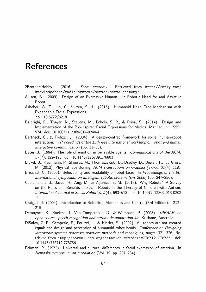
References
2BrothersHobby. (2016). Servo anatomy. Retrieved from http://2bfly.com/knowledgebase/radio-systems/servos/servo-anatomy/
Allison, B. (2009). Design of an Expressive Human-Like Robotic Head for and AssistiveRobot.
Asheber, W. T., Lin, C., & Yen, S. H. (2015). Humanoid Head Face Mechanism withExpandable Facial Expressions.doi: 10.5772/62181
Baldrighi, E., Thayer, N., Stevens, M., Echols, S. R., & Priya, S. (2014). Design andImplementation of the Bio-inspired Facial Expressions for Medical Mannequin. , 555–574. doi: 10.1007/s12369-014-0240-4
Bartneck, C., & Forlizzi, J. (2004). A design-centred framework for social human-robotinteraction. In Proceedings of the 13th ieee international workshop on robot and humaninteractive communication (pp. 31–33).
Bates, J. (1994). The role of emotion in believable agents. Communications of the ACM,37(7), 122–125. doi: 10.1145/176789.176803
Bickel, B., Kaufmann, P., Skouras, M., Thomaszewski, B., Bradley, D., Beeler, T., . . . Gross,M. (2012). Physical face cloning. ACM Transactions on Graphics (TOG), 31(4), 118.
Breazeal, C. (2000). Believability and readability of robot faces. In Proceedings of the 8thinternational symposium on intelligent robotic systems (sirs 2000) (pp. 247–256).
Cabibihan, J. J., Javed, H., Ang, M., & Aljunied, S. M. (2013). Why Robots? A Surveyon the Roles and Benefits of Social Robots in the Therapy of Children with Autism.International Journal of Social Robotics, 5(4), 593–618. doi: 10.1007/s12369-013-0202-2
Craig, J. J. (2004). Introduction to Robotics: Mechanics and Control (3rd Edition). , 212–215.
Demuynck, K., Roelens, J., Van Compernolle, D., & Wambacq, P. (2008). SPRAAK, anopen source speech recognition and automatic annotation kit. Brisbane, Australia.
DiSalvo, C. F., Gemperle, F., Forlizzi, J., & Kiesler, S. (2002). All robots are not createdequal: the design and perception of humanoid robot heads. Conference on Designinginteractive systems processes practices methods and techniques, pages, 321–326. Re-trieved from http://portal.acm.org/citation.cfm?doid=778712.778756 doi:10.1145/778712.778756
Eckman, P. (1972). Universal and cultural differences in facial expression of emotion. InNebraska symposium on motivation (Vol. 19, pp. 207–284).
67

Ellis, D. P. W. (2002). A phase vocoder in Matlab. Retrieved from http://www.ee.columbia.edu/~dpwe/resources/matlab/pvoc/ (Web resource)
Flanagan, J. L., & Golden, R. (1966). Phase vocoder. Bell System Technical Journal , 45(9),1493–1509.
Friesen, E., & Ekman, P. (1978). Facial action coding system: A technique for the measure-ment of facial movement. Palo Alto.
Hanson Robotics. (n.d.). Hanson breakthroughs, from science to art. Retrievedfrom http://www.hansonrobotics.com/hanson-robotics-at-wireds-nextfest-unveiling-zeno/
Hara, F., Akazawa, H., & Kobayashi, H. (2001). Realistic facial expressions by sma drivenface robot. In Robot and human interactive communication, 2001. proceedings. 10thieee international workshop on (pp. 504–511).
Hara, F., & Endo, K. (2000). Dynamic control of lip-configuration of a mouth robot forJapanese vowels. Robotics and Autonomous Systems, 31 , 161–169.
Hashimoto, M., Yokogawa, C., & Sadoyama, T. (2006). Development and Control of a FaceRobot Imitating Human Muscular Structures.
Hashimoto, T., Hiramatsu, S., & Kobayashi, H. (2006). Development of Face Robot forEmotional Communication between Human and Robot. , 25–30.
Hashimoto, T., Senda, M., Shiiba, T., & Kobayshi, H. (2004). Development of the InteractiveReceptionist System by the Face Robot. , 1404–1408.
Jaeckel, P., Campbell, N., & Melhuish, C. (2008). Facial behaviour mapping â From videofootage to a robot head. , 56(12), 1042–1049. Retrieved from http://dx.doi.org/10.1016/j.robot.2008.09.002 doi: 10.1016/j.robot.2008.09.002
Kobayashi, H., Ichikawa, Y., Senda, M., & Shiiba, T. (2002). Toward rich facial expressionby face robot. In Micromechatronics and human science, 2002. mhs 2002. proceedingsof 2002 international symposium on (pp. 139–145).
Lin, C., Cheng, L., & Huang, C. (2012). Visualization of Facial Expression DeformationApplied to the Mechanism Improvement of Face Robot.doi: 10.1007/s12369-012-0168-5
Lin, C., Cheng, L., & Shen, L. (2013). Oral Mechanism Design on Face Robot for Lip-Synchronized Speech. , 4316–4321.
Lin, C., Cheng, L., Tseng, C., Gu, H., Chung, K., Fahn, C., . . . Chang, C. (2011). Aface robot for autonomous simplified musical notation reading and singing. Roboticsand Autonomous Systems, 59(11), 943–953. Retrieved from http://dx.doi.org/10.1016/j.robot.2011.07.001 doi: 10.1016/j.robot.2011.07.001
Lin, C., Huang, C., & Cheng, L. (2011). A Small Number Actuator Mechanism Design forAnthropomorphic Face Robot.
Lin, C., & Huang, H. (2009). Design of a Face Robot with Facial Expression.Loza, D., Marcos, S., Zalama, E., & Jaime, G. (2013). Application of the FACS in the Design
and Construction of a Mechatronic Head with Realistic Appearance. , 7(1), 31–38.Lütkebohle, I., Hegel, F., Schulz, S., Hackel, M., Wrede, B., Wachsmuth, S., & Sagerer,
G. (2010). The Bielefeld anthropomorphic robot head "Flobi". Proceedings - IEEEInternational Conference on Robotics and Automation, 3384–3391. doi: 10.1109/
68

ROBOT.2010.5509173Lutz, W., Sanderson, W., & Scherbov, S. (2008). The coming acceleration of global popu-
lation ageing. Nature, 451(7179), 716–719.Matsumoto, D., & Ekman, P. (2008). Facial expression analysis. Scholarpedia, 3(5), 4237.Mattheyses, W. (2013). A multimodal approach to audiovisual text-to-speech synthesis
(Unpublished doctoral dissertation). Vrije Universiteit Brussel.Mattheyses, W., Latacz, L., & Verhelst, W. (2011). Auditory and photo-realistic audiovisual
speech synthesis for dutch. In Avsp (pp. 55–60).McGurk, H., & MacDonald, J. (1976). Hearing lips and seeing voices. Nature, 264 , 746–748.Mehrabian, A. (1971). Silent messages.Mertens, P., & Vercammen, F. (1997). Fonilex manual.Mori, M., MacDorman, K. F., & Kageki, N. (2012). The uncanny valley [from the field].
Robotics & Automation Magazine, IEEE , 19(2), 98–100.Nourbakhsh, I. R., Bobenage, J., Grange, S., Lutz, R., Meyer, R., & Soto, A. (1999). An
affective mobile robot educator with a full-time job. Artificial Intelligence, 114(1),95–124.
Nowak, K. L., & Rauh, C. (2008). Choose your âbuddy iconâ carefully: The influence ofavatar androgyny, anthropomorphism and credibility in online interactions. Computersin Human Behavior , 24(4), 1473–1493.
Oh, J.-H., Hanson, D., Kim, W.-S., Han, I. Y., Kim, J.-Y., & Park, I.-W. (2006). Designof android type humanoid robot albert hubo. In Intelligent robots and systems, 2006ieee/rsj international conference on (pp. 1428–1433).
Ohala, J. J. (1993). Coarticulation and phonology. Language and speech, 36(2-3), 155–170.Personal Robots Group. (2015). Nexi. Retrieved from http://robotic.media.mit.edu/
portfolio/nexi/Putz, R., & Pabst, R. (2009). Sobotta Atlas of Human Anatomy, Tables of Muscles, Joints
and Nerves (14th ed.). Elsevier.Qingmei, M., Weiguo, W., Yusheng, Z., & Ce, S. (2008). Research and Experiment of Lip
Coordination with Speech for the Humanoid Head Robot-"H&Frobot-III. , 603–608.Sakamoto, S., Hasegawa, G., Ohtani, T., Suzuki, Y., Abe, T., & Kawase, T. (2014).
Contribution of the detailed parts around a talker’s mouth for speech intelligibility.21st International Congress on Sound and Vibration 2014, ICSV 2014 , 3 , 2553–2559. Retrieved from http://www.scopus.com/inward/record.url?eid=2-s2.0-84922612433&partnerID=tZOtx3y1
Saldien, J., Goris, K., Vanderborght, B., Vanderfaeillie, J., & Lefeber, D. (2010). ExpressingEmotions with the Social Robot Probo. International Journal of Social Robotics, 2(4),377–389. Retrieved from http://link.springer.com/10.1007/s12369-010-0067-6 doi: 10.1007/s12369-010-0067-6
Sumby, W. H., & Pollack, I. (1954). Visual contribution to speech intelligibility in noise. Thejournal of the acoustical society of america, 26(2), 212–215.
Tadesse, Y., Hong, D., & Priya, S. (2011). Twelve Degree of Freedom Baby Humanoid HeadUsing Shape Memory Alloy Actuators. , 3(February), 1–18. doi: 10.1115/1.4003005
Thayer, N. D. (2011). Towards a Human-like Robot for Medical Simulation.
69

van Son, T. M. I. B. A. J. S. G. F., Nic; Huiskamp. (1994). Viseme classifications of Dutchconsonants and vowels.doi: 10.1121/1.411324
Waters, K. (1987). A muscle model for animation three-dimensional facial expression. InAcm siggraph computer graphics (Vol. 21, pp. 17–24).
Weiguo, W., Qingmei, M., & Yu, W. (2004). Development of the humanoid head portraitrobot system with flexible face and expression. , 757–762.
Werry, I., Dautenhahn, K., Ogden, B., & Harwin, W. (2001). Can Social Interaction SkillsBe Taught by a Social Agent? The Role of a Robotic Mediator in Autism Therapy.
Wilkes, D. M., Alford, A., Pack, R. T., Rogers, T., Peters, R., & Kawamura, K. (1998).Toward socially intelligent service robots. Applied Artificial Intelligence, 12(7-8), 729–766.
Zhang, L. (2008). Active image labeling and its applications in action unit label-ing. Retrieved from https://www.ecse.rpi.edu/homepages/cvrl/lei/research_activelabeling.htm
70