thin airfoil theorem
TRANSCRIPT
MAE 3241: AERODYNAMICS AND FLIGHT MECHANICS
Thin Airfoil Theory
Mechanical and Aerospace Engineering DepartmentFlorida Institute of Technology
D. R. Kirk
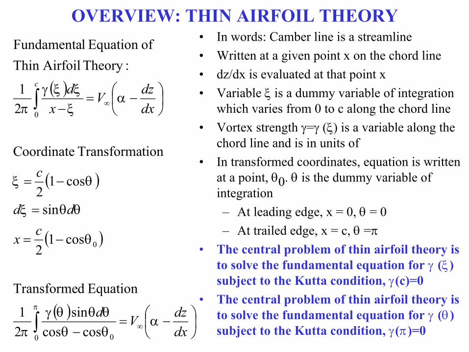
OVERVIEW: THIN AIRFOIL THEORY• In words: Camber line is a streamline• Written at a given point x on the chord line• dz/dx is evaluated at that point x• Variable is a dummy variable of integration
which varies from 0 to c along the chord line• Vortex strength = () is a variable along the
chord line and is in units of • In transformed coordinates, equation is written
at a point, 0. is the dummy variable of integration– At leading edge, x = 0, = 0– At trailed edge, x = c, =
• The central problem of thin airfoil theory is to solve the fundamental equation for () subject to the Kutta condition, (c)=0
• The central problem of thin airfoil theory is to solve the fundamental equation for () subject to the Kutta condition, ()=0
dxdzVd
cx
dd
c
dxdzV
xdc
0 0
0
0
coscossin
21
Equation dTransforme
cos12
sin
cos12
tionTransforma Coordinate
21
:Theory AirfoilThin ofEquation lFundamenta

SUMMARY: SYMMETRIC AIRFOILS
Vd
cx
dd
c
dxdz
dxdzV
xdc
0 0
0
0
coscossin
21
Equation dTransforme
cos12
sin
cos12
tionTransforma Coordinate
0
:airfoils Symmetric
21
:Theory AirfoilThin ofEquation lFundamenta

SUMMARY: SYMMETRIC AIRFOILS
0cossin2
002
sincos12
coscossin
21 2
0 0
V
V
V
Vd• Fundamental equation of thin airfoil theory for
a symmetric airfoil (dz/dx=0) written in transformed coordinates
• Solution– “A rigorous solution for () can be
obtained from the mathematical theory of integral equations, which is beyond the scope of this book.” (page 324, Anderson)
• Solution must satisfy Kutta condition ()=0 at trailing edge to be consistent with experimental results
• Direct evaluation gives an indeterminant form, but can use L’Hospital’s rule to show that Kutta condition does hold.

SUMMARY: SYMMETRIC AIRFOILS• Total circulation, , around the airfoil (around the
vortex sheet described by ())
• Transform coordinates and integrate
• Simple expression for total circulation
• Apply Kutta-Joukowski theorem (see §3.16), “although the result [L’=∞V ∞
2] was derived for a circular cylinder, it applies in general to cylindrical bodies of arbitrary cross section.”
• Lift coefficient is linearly proportional to angle of attack
• Lift slope is 2/rad or 0.11/deg
2
2
sin2
2
0
0
ddcc
VcVL
cV
dc
d
l
l
c
EXAMPLE: NACA 65-006 SYMMETRIC AIRFOIL
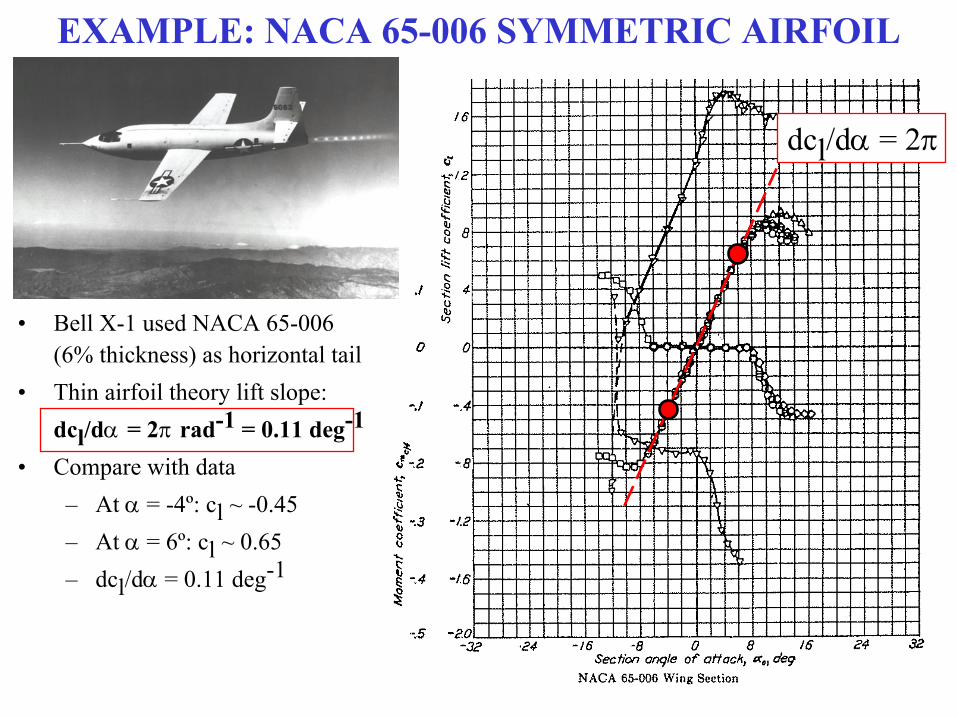
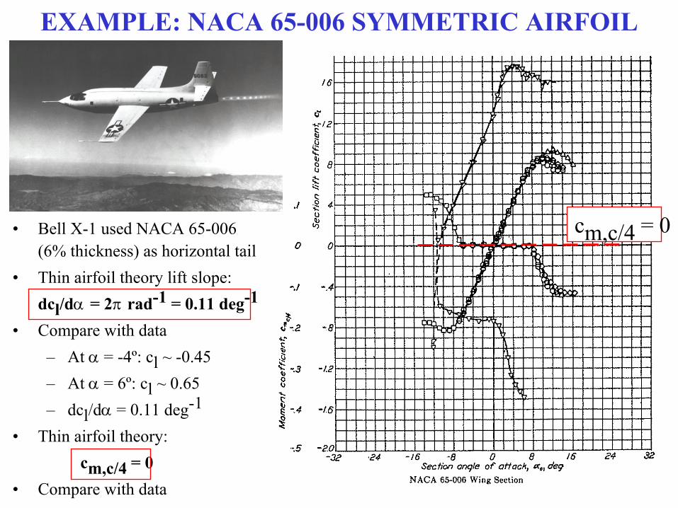
• Bell X-1 used NACA 65-006 (6% thickness) as horizontal tail
• Thin airfoil theory lift slope:dcl/d = 2 rad-1 = 0.11 deg-1
• Compare with data– At = -4º: cl ~ -0.45– At = 6º: cl ~ 0.65– dcl/d = 0.11 deg-1
dcl/d = 2
SUMMARY: SYMMETRIC AIRFOILS
0
4
4
221
221
4,
,4,
,
2,
22
00
cm
llemcm
llem
LElem
LE
cc
LE
c
ccc
cc
ScV
Mc
cVM
dVdLM
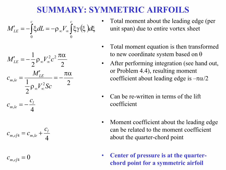
• Total moment about the leading edge (per
unit span) due to entire vortex sheet
• Total moment equation is then transformed to new coordinate system based on
• After performing integration (see hand out, or Problem 4.4), resulting moment coefficient about leading edge is –/2
• Can be re-written in terms of the lift coefficient
• Moment coefficient about the leading edge can be related to the moment coefficient about the quarter-chord point
• Center of pressure is at the quarter-chord point for a symmetric airfoil
EXAMPLE: NACA 65-006 SYMMETRIC AIRFOIL
• Bell X-1 used NACA 65-006 (6% thickness) as horizontal tail
• Thin airfoil theory lift slope:dcl/d = 2 rad-1 = 0.11 deg-1
• Compare with data– At = -4º: cl ~ -0.45– At = 6º: cl ~ 0.65– dcl/d = 0.11 deg-1
• Thin airfoil theory:cm,c/4 = 0
• Compare with data
cm,c/4 = 0
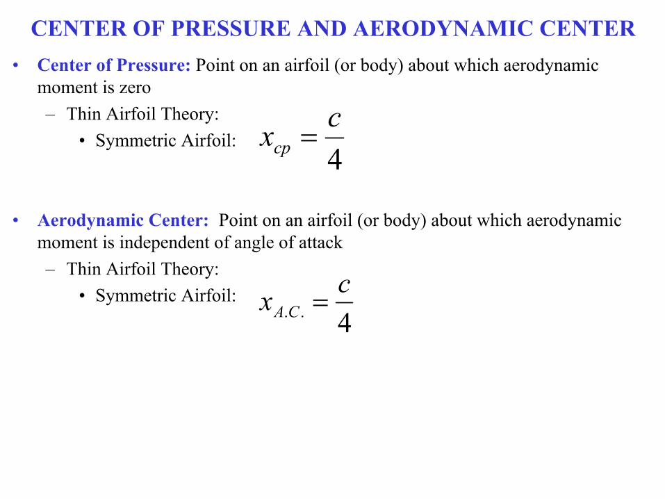
CENTER OF PRESSURE AND AERODYNAMIC CENTER• Center of Pressure: Point on an airfoil (or body) about which aerodynamic
moment is zero– Thin Airfoil Theory:
• Symmetric Airfoil:
• Aerodynamic Center: Point on an airfoil (or body) about which aerodynamic moment is independent of angle of attack– Thin Airfoil Theory:
• Symmetric Airfoil:
4cxcp
4..cx CA
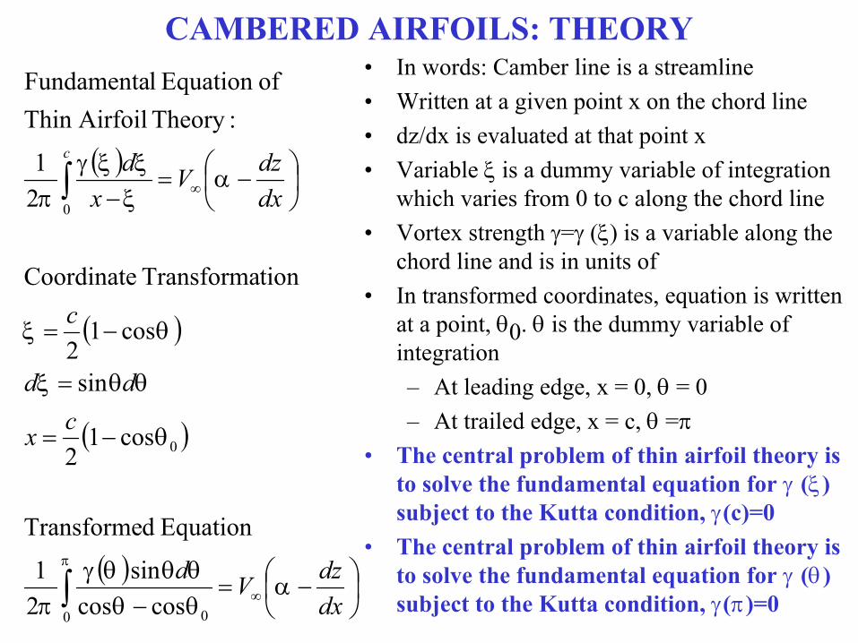
CAMBERED AIRFOILS: THEORY• In words: Camber line is a streamline• Written at a given point x on the chord line• dz/dx is evaluated at that point x• Variable is a dummy variable of integration
which varies from 0 to c along the chord line• Vortex strength = () is a variable along the
chord line and is in units of • In transformed coordinates, equation is written
at a point, 0. is the dummy variable of integration– At leading edge, x = 0, = 0– At trailed edge, x = c, =
• The central problem of thin airfoil theory is to solve the fundamental equation for () subject to the Kutta condition, (c)=0
• The central problem of thin airfoil theory is to solve the fundamental equation for () subject to the Kutta condition, ()=0
dxdzVd
cx
dd
c
dxdzV
xdc
0 0
0
0
coscossin
21
Equation dTransforme
cos12
sin
cos12
tionTransforma Coordinate
21
:Theory AirfoilThin ofEquation lFundamenta
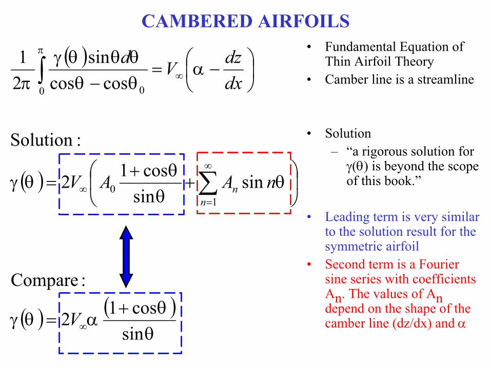
CAMBERED AIRFOILS• Fundamental Equation of
Thin Airfoil Theory• Camber line is a streamline
• Solution– “a rigorous solution for
() is beyond the scope of this book.”
• Leading term is very similar to the solution result for the symmetric airfoil
• Second term is a Fourier sine series with coefficients An. The values of An depend on the shape of the camber line (dz/dx) and
sincos12
:Compare
sinsin
cos12
:Solution
coscossin
21
10
0 0
V
nAAV
dxdzVd
nn

EVALUATION PROCEDURE
dxdzdnAdA
nAAV
dxdzVd
n
n
nn
1 0 00 0
0
10
0 0
coscossinsin1
coscoscos11
sinsin
cos12
coscossin
21
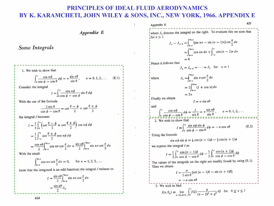
PRINCIPLES OF IDEAL FLUID AERODYNAMICSBY K. KARAMCHETI, JOHN WILEY & SONS, INC., NEW YORK, 1966. APPENDIX E

PRINCIPLES OF IDEAL FLUID AERODYNAMICSBY K. KARAMCHETI, JOHN WILEY & SONS, INC., NEW YORK, 1966. APPENDIX E

CAMBERED AIRFOILS
0
00
10
100
100
cos2
1
cos
cos
cos
dnfB
dfB
nBBf
nAAdxdz
dxdznAA
n
nn
nn
nn
• After making substitutions of standard forms available in advanced math textbooks
• We can solve this expression for dz/dx which is a Fourier cosine series expansion for the function dz/dx, which describes the camber of the airfoil
• Examine a general Fourier cosine series representation of a function f() over an interval 0 ≤ ≤
• The Fourier coefficients are given by B0 and Bn
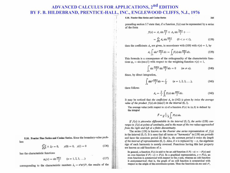
ADVANCED CALCULUS FOR APPLICATIONS, 2nd EDITIONBY F. B. HILDEBRAND, PRENTICE-HALL, INC., ENGLEWOOD CLIFFS, N.J., 1976
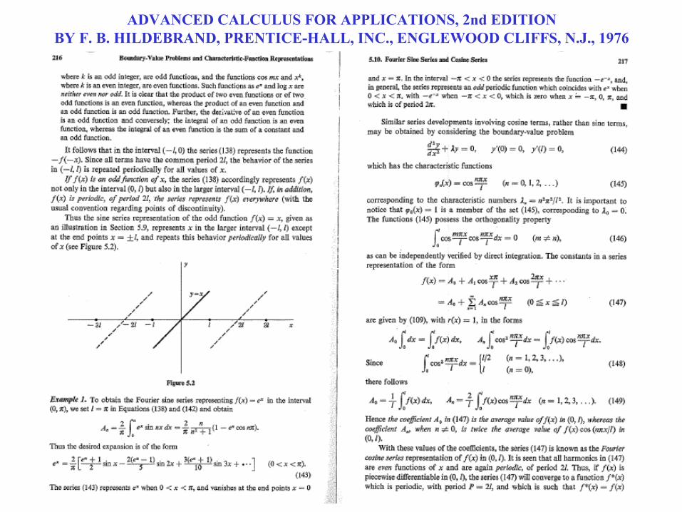
ADVANCED CALCULUS FOR APPLICATIONS, 2nd EDITIONBY F. B. HILDEBRAND, PRENTICE-HALL, INC., ENGLEWOOD CLIFFS, N.J., 1976
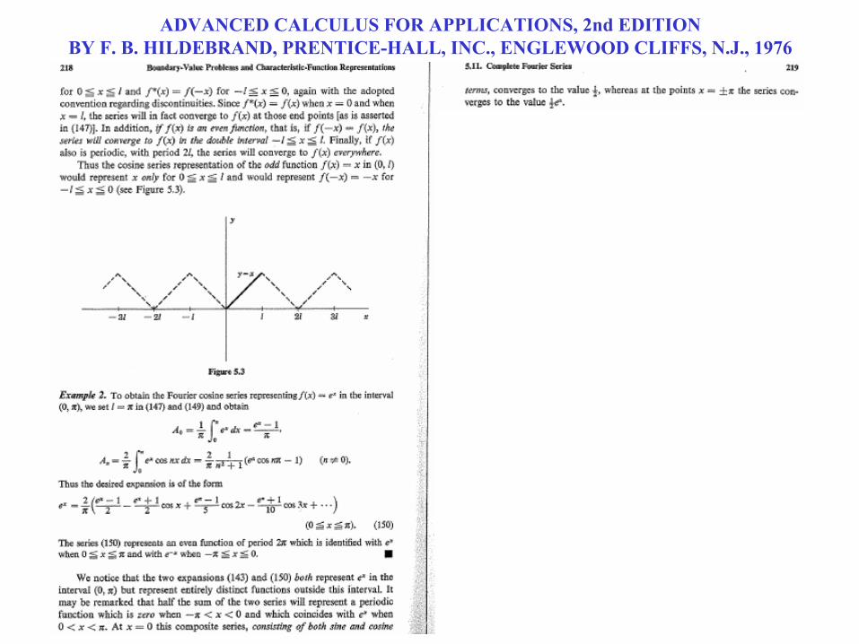
ADVANCED CALCULUS FOR APPLICATIONS, 2nd EDITIONBY F. B. HILDEBRAND, PRENTICE-HALL, INC., ENGLEWOOD CLIFFS, N.J., 1976

CAMBERED AIRFOILS
000
000
000
cos2
1
1
dndxdzA
ddxdzA
ddxdzA
n
• Compare Fourier expansion of dz/dx with general Fourier cosine series expansion
• Analogous to the B0 term in the general expansion
• Analogous to the Bn term in the general expansion
CAMBERED AIRFOILS
10
0 1 00
10
0
0
2
sinsincos1
sinsin
cos12
:for solution general Recall
sin2
AAcV
dnAdAcV
nAAV
dc
d
nn
nn
c
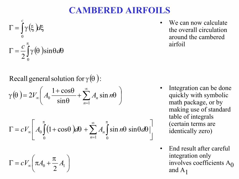
• We can now calculate the overall circulation around the cambered airfoil
• Integration can be done quickly with symbolic math package, or by making use of standard table of integrals (certain terms are identically zero)
• End result after careful integration only involves coefficients A0 and A1

CAMBERED AIRFOILS
2
1cos12
2
21
2
2
000
102
102
10
ddc
ddxdzc
AASV
Lc
AAcVL
AAcV
VL
l
l
l
• Calculation of lift per unit span
• Lift per unit span only involves coefficients A0 and A1
• Lift coefficient only involves coefficients A0 and A1
• The theoretical lift slope for a cambered airfoil is 2 , which is a general result from thin airfoil theory
• However, note that the expression for cl differs from a symmetric airfoil
CAMBERED AIRFOILS
0000
000
0
0
1cos1
1cos12
2
ddxdz
ddxdzc
c
ddcc
L
l
Ll
Ll
l
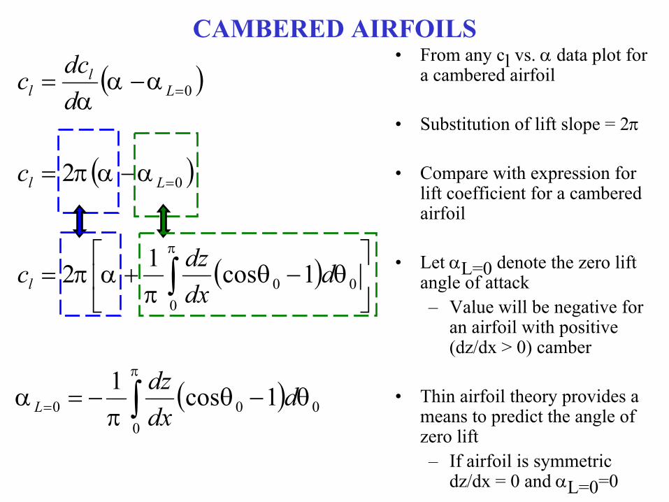
• From any cl vs. data plot for a cambered airfoil
• Substitution of lift slope = 2
• Compare with expression for lift coefficient for a cambered airfoil
• Let L=0 denote the zero lift angle of attack– Value will be negative for
an airfoil with positive (dz/dx > 0) camber
• Thin airfoil theory provides a means to predict the angle of zero lift– If airfoil is symmetric
dz/dx = 0 and L=0=0

SAMPLE DATA: SYMMETRIC AIRFOIL
Lift
Coe
ffic
ient
Angle of Attack,
A symmetric airfoil generates zero lift at zero
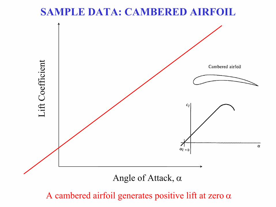
SAMPLE DATA: CAMBERED AIRFOIL
Lift
Coe
ffic
ient
Angle of Attack,
A cambered airfoil generates positive lift at zero
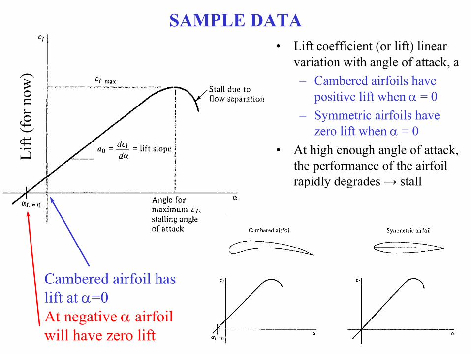
SAMPLE DATA• Lift coefficient (or lift) linear
variation with angle of attack, a– Cambered airfoils have
positive lift when = 0– Symmetric airfoils have
zero lift when = 0• At high enough angle of attack,
the performance of the airfoil rapidly degrades → stall
Lift
(for
now
)
Cambered airfoil haslift at =0At negative airfoilwill have zero lift
AERODYNAMIC MOMENT ANALYSIS
22
sin2
cos12
1
221
21
sinsin
cos12
210,
0,
02,
222,
10
00
AAAc
dcV
c
dcV
c
cV
M
ScV
Mc
nAAV
dVdLM
lem
lem
c
lem
LELElem
nn
cc
LE
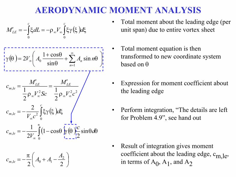
• Total moment about the leading edge (per unit span) due to entire vortex sheet
• Total moment equation is then transformed to new coordinate system based on
• Expression for moment coefficient about the leading edge
• Perform integration, “The details are left for Problem 4.9”, see hand out
• Result of integration gives moment coefficient about the leading edge, cm,le, in terms of A0, A1, and A2

AERODYNAMIC MOMENT SUMMARY
21
124,
21,
210,
14
4
44
22
AAc
cx
AAc
AAcc
AAAc
lcp
cm
llem
lem
• Aerodynamic moment coefficient about leading
edge of cambered airfoil
• Can re-writte in terms of the lift coefficient, cl– For symmetric airfoil
• dz/dx=0• A1=A2=0• cm,le=-cl/4
• Moment coefficient about quarter-chord point– Finite for a cambered airfoil
• For symmetric cm,c/4=0– Quarter chord point is not center of
pressure for a cambered airfoil– A1 and A2 do not depend on
• cm,c/4 is independent of – Quarter-chord point is theoretical location
of aerodynamic center for cambered airfoils

CENTER OF PRESSURE AND AERODYNAMIC CENTER• Center of Pressure: Point on an airfoil (or body) about which aerodynamic
moment is zero– Thin Airfoil Theory:
• Symmetric Airfoil:• Cambered Airfoil:
• Aerodynamic Center: Point on an airfoil (or body) about which aerodynamic moment is independent of angle of attack– Thin Airfoil Theory:
• Symmetric Airfoil:• Cambered Airfoil:
2114
4
AAc
cx
cx
lcp
cp
4
4
..
..
cx
cx
CA
CA

ACTUAL LOCATION OF AERODYNAMIC CENTER
NACA 23012xA.C. < 0.25c
NACA 64212xA.C. > 0.25 c
x/c=0.25
x/c=0.25

IMPLICATIONS FOR STALL
• Flat Plate Stall
• Leading Edge Stall
• Trailing Edge Stall
Increasing airfoilthickness
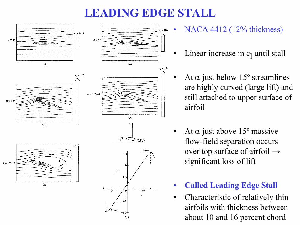
LEADING EDGE STALL• NACA 4412 (12% thickness)
• Linear increase in cl until stall
• At just below 15º streamlines are highly curved (large lift) and still attached to upper surface of airfoil
• At just above 15º massive flow-field separation occurs over top surface of airfoil → significant loss of lift
• Called Leading Edge Stall• Characteristic of relatively thin
airfoils with thickness between about 10 and 16 percent chord

TRAILING EDGE STALL
• NACA 4421 (21% thickness)• Progressive and gradual movement of separation from trailing edge toward leading
edge as is increased• Called Trailing Edge Stall
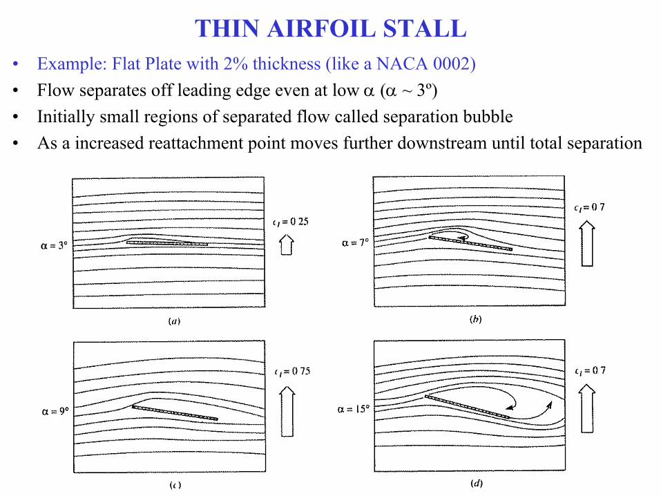
THIN AIRFOIL STALL• Example: Flat Plate with 2% thickness (like a NACA 0002)• Flow separates off leading edge even at low ( ~ 3º)• Initially small regions of separated flow called separation bubble• As a increased reattachment point moves further downstream until total separation

NACA 4412 vs. NACA 4421• NACA 4412 and NACA 4421 have
same shape of mean camber line• Theory predicts that linear lift slope
and L=0 same for both
• Leading edge stall shows rapid drop of lift curve near maximum lift
• Trailing edge stall shows gradual bending-over of lift curve at maximum lift, “soft stall”
• High cl,max for airfoils with leading edge stall
• Flat plate stall exhibits poorest behavior, early stalling
• Thickness has major effect on cl,max
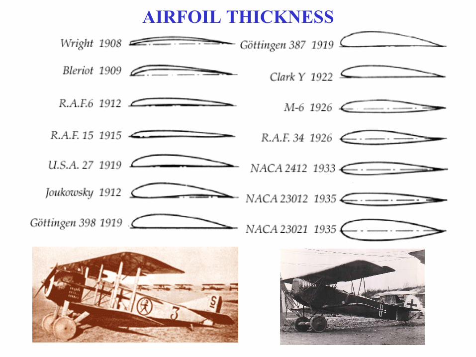
AIRFOIL THICKNESS

AIRFOIL THICKNESS: WWI AIRPLANES
English Sopwith Camel
German Fokker Dr-1
Higher maximum CLInternal wing structureHigher rates of climbImproved maneuverability
Thin wing, lower maximum CLBracing wires required – high drag
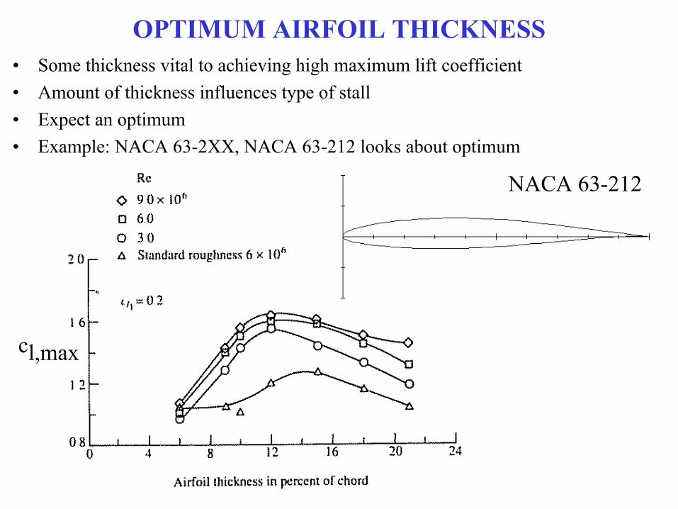
OPTIMUM AIRFOIL THICKNESS• Some thickness vital to achieving high maximum lift coefficient• Amount of thickness influences type of stall• Expect an optimum• Example: NACA 63-2XX, NACA 63-212 looks about optimum
cl,max
NACA 63-212
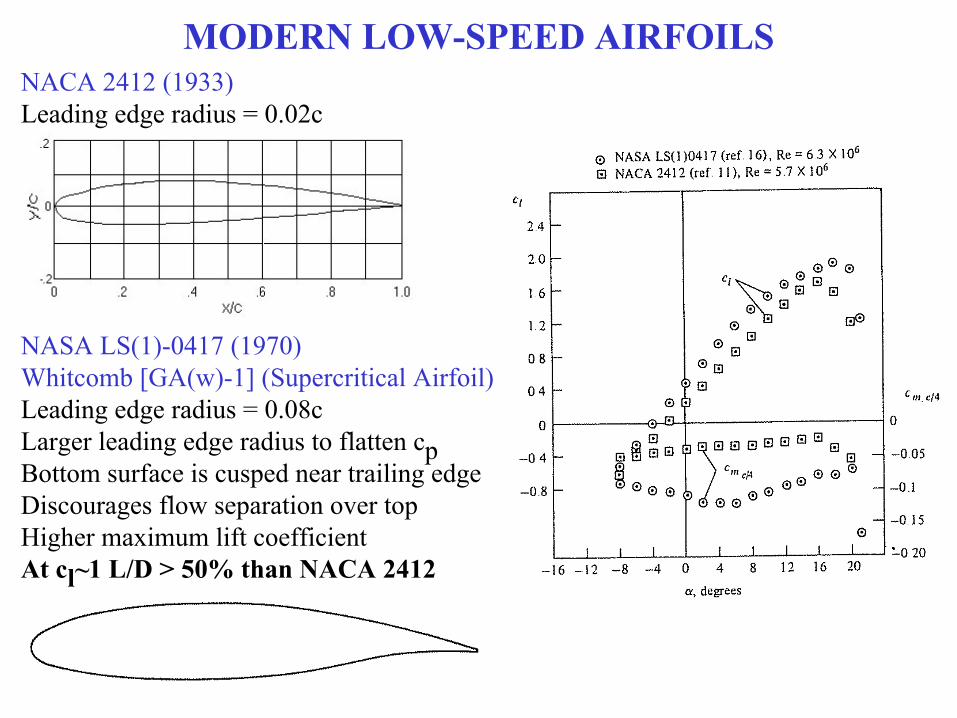
MODERN LOW-SPEED AIRFOILSNACA 2412 (1933)Leading edge radius = 0.02c
NASA LS(1)-0417 (1970)Whitcomb [GA(w)-1] (Supercritical Airfoil)Leading edge radius = 0.08cLarger leading edge radius to flatten cpBottom surface is cusped near trailing edgeDiscourages flow separation over topHigher maximum lift coefficientAt cl~1 L/D > 50% than NACA 2412
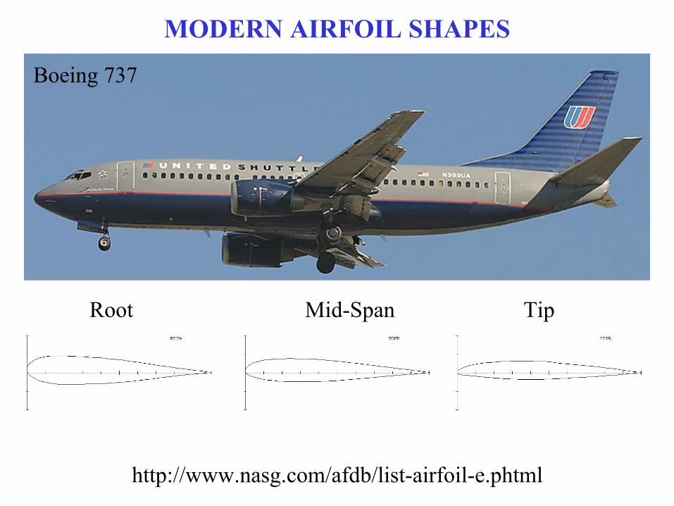
MODERN AIRFOIL SHAPES
http://www.nasg.com/afdb/list-airfoil-e.phtml
Root Mid-Span Tip
Boeing 737