this user manual describes all items concerning the
TRANSCRIPT

Foreword
This user manual describes all items concerning the operation of the
system in detail as much as possible. However, it is impractical to give particular
descriptions of all unnecessary and/or unavailable operations of the system due
to the manual content limit, product specific operations and other causes.
Therefore, the operations not specified herein should be considered impossible or
unallowable.
This user manual is the property of GSK CNC Equipment Co., Ltd. All
rights are reserved. It is against the law for any organization or individual to
publish or reprint this manual without the express written permission of GSK and
the latter reserves the right to ascertain their legal liability.

GSK980TA3 Series Turning CNC System User Manual
II
The User Manual is applied to the following CNC systems:
Type structure LCD size Remark
GSK980TA3 horizontal 7.0 LCD size is defaulted to be
7.0 inch
GSK980TA3 is upgrading products of GSK980TA2, which can control
three feed shaft, a spindle , and add the function of automatic feeding,
groove cycle processing(G71) and so on, which can significantly improve the
efficiency of machining parts, precision and surface roughness.
As GSK980TA2 upgrades, GSK980TA3 is the best choice of the
economical cnc lathe technology upgrading.

Foreword
III
FOREWORD
Dear user,
We are really grateful for your patronage and purchase of this turning CNC system
of GSK980TA3 series made by GSK CNC Equipment Co., Ltd.
The user manual describes the programming, operation, installation and
connection. Please read it carefully before operation in order to get the safe and
effective working.
WARNING
This system can only be operated by authorized and qualified personnel as
improper operations may cause accidents.
Please carefully read this user manual before use!
Note: The power supply installed on (in) the cabinet is exclusive to GSK’S CNC
systems.
The power supply form is forbidden to be used for other purposes.
Otherwise, there may be extreme danger!

GSK980TA3 Series Turning CNC System User Manual
IV
SAFETY PRECAUTION
Warning, caution and note
This manual includes safety precaution for protecting the user and preventing
damage to the machine. Precautions are clssified into Warning and Caution
according totheir bearing on safety. Read the Warning, Caution and Note
thoroughly before attempting to use the machine.
Warning
There is a danger of the user being injured or the equipment being damaged if
the approved procedure is not observed.
Caution
There is a danger of the equipment being damaged if the approved procedure is
not observed.
Note
It is used to indicate supplementary information other than Warning and
Caution.

Foreword
V
Delivery and storage Packing box over 6 layers in pile is unallowed.
Never climb the packing box, neither stand on it, nor place heavy objects on it.
Do not move or drag the product by the cables connected with it.
Forbid collision or scratch to the panel and displayer.
Packing box should be protected from damping, insolation and raining.
Open packing box to check Ensure things in packing box are the required ones.
Ensure the product is not damaged in delivery.
Ensure the parts in packing box are in accordance to the order.
Contact us in time if the product type is inconsistent with the order, there is short
of accessories, or product damage in delivery.
Connection Only qualified persons can connect the system or check the connection.
The system must be earthed, its resistance must be less than 4 Ω and the
ground wire cannot be replaced by zero wire.
Connection must be correct and firm to avoid the product to be damaged or other
unexpected result.
Connect with surge diode in the specified direction to avoid the damage to the
system.
Switch off power supply before pulling out plug or opening electric cabinet.
Troubleshooting Switch off power supply before troubleshooting or changing components.
Troubleshoot and then startup the system when there is short circuit or overload.
Do not switch on or off it frequently and an interval is 1 minute at least after the
system is powered on again.

GSK980TA3 Series Turning CNC System User Manual
VI
SAFETY RESPONSIBILITY
Manufacturer’s safety responsibility
——The manufacturer should be responsible for the cleared or the controlled safety in
the design and the structure of the CNC system and the accessories.
——The manufacturer should be responsible for the CNC system and the
accessories.
——The manufacturer should be responsible for the message and the suggestion for
the user.
User’s safety responsibility
——The user should study and train the system safety operation, master the safety
operation content.
——The user should be responsible for the danger caused by increasing, changing or
modifying the CNC system, the accessories by itself.
——The user should be responsible for the danger because of the mistaken operation,
regulation, maintenance, installation and storage.
This user manual shall be kept by final user.
All specification and designs are subject to change without further notice.

Contents
VII
Contents
CONTENTS ..................................................................................................................................................... VII
PART ONE SUMMARY ................................................................................................................................. 1
CHAPTER ONE SUMMARY ................................................................................................................................... 3 1.1 Summary ........................................................................................................................................................ 3 1.2 Product Brief .................................................................................................................................................. 3 1.3 Model and Meaning ...................................................................................................................................... 4 1.4 Order ............................................................................................................................................................... 4
PART TWO PROGRAMMING ........................................................................................................................ 5
CHAPTER ONE PROGRAMMING FUNDATION ............................................................................................. 7 1.1 Coordinate axis definition ............................................................................................................................ 7 1.2 Machine coordinate system, Machine Zero .............................................................................................. 8 1.3 Workpiece Coordinate System & Reference Point (Program Zero) ...................................................... 8 1.4 Controlled axes ............................................................................................................................................. 9 1.5 Input Increment ........................................................................................................................................... 10 1.6 Maximum Stroke ......................................................................................................................................... 10 1.7 Absolute Programming & Incremental Programming ............................................................................ 10 1.8 Diameter and Radius Programming ......................................................................................................... 11 1.9 Modal, Simple and Initial State ................................................................................................................. 12
CHAPTER TWO STRUCTURE OF AN PART PROGRAM ............................................................................ 15 2.1 General Structure of a Program ................................................................................................................ 15
2.1.1 Program Name ........................................................................................................................................ 15 2.1.2 Sequence Number and Block .................................................................................................................. 16 2.1.3 Word ....................................................................................................................................................... 16
2.2 Relationship between Command Numerical Value and Decimal Point ............................................ 18 2.3 Subprogram ................................................................................................................................................. 19
2.3.1 Main Program and Subprogram .............................................................................................................. 19 2.3.2 Subprogram Call(M98) ..................................................................................................................... 20 2.3.3 Return from subprogram(M99) ......................................................................................................... 20
CHAPTER THREE PREPARATORY FUNCTION G CODE .......................................................................... 22 3.1 Category of Preparatory Function G Code ............................................................................................. 22 3.2 Simple G Code ............................................................................................................................................ 24
3.2.1 Rapid Positioning(G00) ..................................................................................................................... 24 3.2.2 Linear Interpolation(G01).................................................................................................................. 26 3.2.3 Circular Interpolation(G02/G03) ....................................................................................................... 27 3.2.4 Chamfering/Cornering Arc ..................................................................................................................... 30 3.2.5 Dwell G04 ............................................................................................................................................... 31 3.2.6 Programs Specifying Parameter Function (G10) .............................................................................. 31 3.2.7 Machine Zero Return(G28) ............................................................................................................... 32 3.2.8 Workpiece Coordinate System Setting(G50) ..................................................................................... 33 3.2.9 Workpiece Coordinate System Offset(G51) ...................................................................................... 35 3.2.10 Feed per minute (G98) .......................................................................................................................... 36 3.2.11 Feed per Rev (G99) ............................................................................................................................... 36 3.2.12 Constant Surface Control (G96, G97) ................................................................................................... 37 3.2.13 Skip Function (G31) ....................................................................................................................... 39 3.2.14 Thread Cutting with Invariable Pitch(G32) ..................................................................................... 40 3.2.15 Thread Cutting with Variable Pitch(G34) ........................................................................................ 43 3.2.16 Tapping Cycle(G33) ........................................................................................................................ 44
3.3 Single Fixed Cycle Command .................................................................................................................. 45

GSK980TA3 Series Turning CNC System User Manual
VIII
3.3.1 Outer(Inner)Cutting Cycle(G90) .................................................................................................. 46 3.3.2 End Cutting Cycle(G94) ................................................................................................................... 48 3.3.3 Thread Cutting Cycle(G92) ............................................................................................................... 51 3.3.4 Notes in Single Fixed Cycle Commands ................................................................................................ 54
3.4 Compound Fixed Cycle Commands ........................................................................................................ 54 3.4.1 Outer(Inner)Roughing Cycle(G71) .............................................................................................. 54 3.4.2 End Roughing Cycle(G72) ................................................................................................................ 58 3.4.3 Closed Cutting Cycle(G73) ............................................................................................................... 61 3.4.4 Finishing Cycle(G70) ........................................................................................................................ 64 3.4.5 End Deep Hole Machining Cycle(G74) ............................................................................................ 65 3.4.6 Outer Grooving Cycle(G75) .............................................................................................................. 67 3.4.7 Compound Thread Cutting Cycle(G76) ............................................................................................ 69 3.4.8 Notes of Compound Fixed Cycle Codes ................................................................................................ 72
CHAPTER FOUR MISCELLANEOUS FUNCTION M CODE ...................................................................... 73 4.1 Miscellaneous Function (M function) ................................................................................................. 73 4.2 Special M Codes(M21.M22.M23.M24 ) ............................................................................................ 75 4.3 M Code Calling Subprograms .................................................................................................................. 76 4.4 S Codes Calling Subprograms ................................................................................................................. 76 4.5 T Codes Calling Subprograms ................................................................................................................. 76 4.6 Parameters of Miscellaneous Function ................................................................................................... 77 4.7 Alarm Related to Miscellaneous Function .............................................................................................. 77
CHAPTER FIVE SPINDLE FUNCTION S CODE ........................................................................................... 80 5.1 Spindle Switching Value Control .............................................................................................................. 80 5.2 Spindle Analog Value Control ................................................................................................................... 80
CHAPTER SIX TOOL FUNCTION T CODE .................................................................................................... 82 6.1 Tool change Process .................................................................................................................................. 82 6.2 Relevant Parameters of Tool Change ..................................................................................................... 83 6.3 Tool Offset ................................................................................................................................................... 84
6.3.1 Basic Tool Offset .................................................................................................................................... 84 6.3.2 T Code for tool offset ............................................................................................................................. 85 6.3.3 Offset ...................................................................................................................................................... 85 6.3.4 Programming Example ........................................................................................................................... 87 6.3.5 Single T code .......................................................................................................................................... 87
CHAPTER SEVEN USER MACRO PROGRAM ............................................................................................. 90 7.1 User Macro Code ....................................................................................................................................... 90 7.2 User Macro Program Body ....................................................................................................................... 90 7.3 Operation Command and Transfer Command(G65) ....................................................................... 94 7.4 Notes for User Macro Program Body ...................................................................................................... 98 7.5 User Macro Program Example ................................................................................................................. 99
CHAPTER EIGHT TOOL COMPENSATION C FUNCTION ...................................................................... 100 8.1 Basic Concept of Tool Compensation C Function ............................................................................... 100
8.1.1 Imaginary Tool Nose ............................................................................................................................ 100 8.1.2 Imaginary Tool Nose Direction ............................................................................................................ 102 8.1.3 Compensation Value Setting ................................................................................................................. 106 8.1.4 Relative Position between Tool and Workpiece ................................................................................... 106 8.1.5 Inside and outside ................................................................................................................................. 108 8.1.6 Command Format of G41, G42, G40 ................................................................................................... 109
8.2 Concrete Tool Compensation ................................................................................................................. 109 8.2.1 Concrete Path Decomposition of Tool Nose Radius Compensation ..................................................... 109 8.2.2 Compensation direction change when tool compensation proceeding .................................................. 116 8.2.3 Temporary Tool Compensation Cancel ................................................................................................. 118 8.2.4 Non-Movement Command when Tool Compensation ......................................................................... 120 8.2.5 Tool Compensation Interference Check ............................................................................................... 121 8.2.6 Tool Nose Radius Compensation in G90/G94 ...................................................................................... 123 8.2.7 Tool Nose Radius Compensation in G70 .............................................................................................. 125

Contents
IX
8.3 Notes of Tool Compensation C ............................................................................................................... 125 8.4 Tool Compensation C Example .............................................................................................................. 126
PART THREE OPERATION ..................................................................................................................... 131
CHAPTER ONE OPERATION PANEL............................................................................................................ 133 1.1 Panel division ............................................................................................................................................ 133 1.2 Instructions for Panel Functions ............................................................................................................. 134
1.2.1 LCD (liquid crystal) display area .......................................................................................................... 134 1.2.2 Edit Keypad Area .................................................................................................................................. 134 1.2.3 Introduction for Screen Operation Keys ............................................................................................... 135 1.2.4 Machine Control Area ........................................................................................................................... 135
CHAPTER TWO SYSTEM POWER ON/OFF & SAFETY OPERATION ................................................... 140 2.1 System Power-on ..................................................................................................................................... 140 2.2 System Power-off ..................................................................................................................................... 140 2.3 Safety Operation ....................................................................................................................................... 141
2.3.1 Reset ..................................................................................................................................................... 141 2.3.2 Emergency Stop .................................................................................................................................... 141 2.3.3 Feed Hold ............................................................................................................................................. 142 2.3.4 Power-off .............................................................................................................................................. 142
2.4 Cycle Start and Feed Hold ...................................................................................................................... 142 2.5 Overtravel Protection ............................................................................................................................... 142
2.5.1 Hardware Overtravel Protection ........................................................................................................... 142 2.5.2 Software Overtravel Protection ............................................................................................................. 143
CHAPTER THREE INTERFACE DISPLAY & DATA MODIFICATION & SETTING ............................. 144 3.1 Position Display ........................................................................................................................................ 144
3.1.1 Four Ways for Interface Display ........................................................................................................... 144 3.1.2 Display of Machining Time, Parts Number, Programming Speed, Override and Actual Speed ........... 146 3.1.3 Clearing Methods of Parts Number and Cutting Time .......................................................................... 147
3.2 Program Display ....................................................................................................................................... 147 3.3 Display, Modification and Setting of the Tool Offset ............................................................................ 149
3.3.1 Tool Offset Display ............................................................................................................................... 149 3.3.2 Tool Offset Modification and Setting ................................................................................................... 150
3.4 Alarm Display ............................................................................................................................................ 151 3.5 Setting Display .......................................................................................................................................... 152
3.5.1 Instruction for 【Setting】Interface Operation ................................................................................... 152 3.5.2 Operating Instructions for 【Graph】Interface ................................................................................... 154
3.6 Display, Modification and Setting of the Parameter ............................................................................. 156 3.6.1 Parameter Display ................................................................................................................................. 156 3.6.2 Modification and Setting for Parameter and Screw Pitch Compensation Value ................................... 157
3.7 Diagonosis Display ................................................................................................................................... 159 3.7.1 Diagnosis Data Display ........................................................................................................................ 160
CHAPTER FOUR MANUAL OPERATION .................................................................................................... 162 4.1 Coordinate Axis Movement ........................................................................................................................ 162
4.1.1 Manual Feed ......................................................................................................................................... 162 4.1.2 Manual Rapid Traverse ......................................................................................................................... 162 4.1.3 Manual Feed and Manual Rapid Traverse Rate Selection .................................................................... 163
4.2 Spindle Control .......................................................................................................................................... 164 4.2.1 Spindle CW (Negative rotation) ........................................................................................................... 164 4.2.2 Spindle CCW (Positive rotation) .......................................................................................................... 164 4.2.3 Spindle Stop .......................................................................................................................................... 164
4.3 Other Manual Operations ........................................................................................................................ 164 4.3.1 Cooling Control .................................................................................................................................... 164 4.3.2 Lubricating Control............................................................................................................................... 164 4.3.3 Manual Tool Change ............................................................................................................................. 165
4.4 Tool Setting ................................................................................................................................................ 165 4.4.1 Fixed-point Tool Setting ....................................................................................................................... 165

GSK980TA3 Series Turning CNC System User Manual
X
4.4.2 Tool Setting by Test Cutting ................................................................................................................. 166 4.4.3 Tool Setting by Machine Zero Return .................................................................................................. 168
4.5 Offset Alteration ........................................................................................................................................ 171
CHAPTER FIVE MPG/SINGLE-STEP OPERATION ................................................................................... 172 5.1 Step Feed .................................................................................................................................................. 172 5.2 MPG (Manual pulse generator) Feed .................................................................................................... 173
5.2.1 Moving Axis and Direction Selection .................................................................................................. 173 5.2.2 Instructions for MPG Feed ................................................................................................................... 174
5.3 The Miscellaneous Control in MPG/Step Operation ........................................................................... 175
CHAPTER SIX MDI OPERATION .................................................................................................................. 176 6.1 MDI Blocks Input ...................................................................................................................................... 176 6.2 MDI Block Operation and Stop ............................................................................................................... 177 6.3 MDI Block Words Alteration and Clearing ............................................................................................. 177 6.4 Conversion of Operation Modes ............................................................................................................ 177
CHAPTER SEVEN EDIT OPERATION .......................................................................................................... 178 7.1 Program Edit ............................................................................................................................................. 178
7.1.1 Program Creation ................................................................................................................................. 178 7.1.2 Deletion of a program ........................................................................................................................... 182 7.1.3 Deletion of All Programs ...................................................................................................................... 183 7.1.4 Duplication of the Program .................................................................................................................. 183 7.1.5 Rename of the Program ........................................................................................................................ 183
7.2 Program Management ............................................................................................................................. 184 7.2.1 Search of Program List ......................................................................................................................... 184 7.2.2 Quantity of the Saved Programs ........................................................................................................... 184 7.2.3 Memory Capacity ................................................................................................................................. 184 7.2.4 Program Lock ....................................................................................................................................... 185
7.3 Other Operations Available in Edit Mode .............................................................................................. 185
CHAPTER EIGHT AUTO OPERATION ......................................................................................................... 186 8.1 Selection of the Program To Be Run ..................................................................................................... 186 8.2 Start of the Auto Run ................................................................................................................................ 186 8.3 Auto Run Stop ........................................................................................................................................... 187 8.4 Auto Run From an Arbitrary Block ......................................................................................................... 188 8.5 Dry Run ...................................................................................................................................................... 188 8.6 Single Block Execution ............................................................................................................................ 189 8.7 Machine Lock ............................................................................................................................................ 191 8.8 M. S. T Lock .............................................................................................................................................. 192 8.9 Block Skip .................................................................................................................................................. 192 8.10 Ajustment of the Feedrate, Rapid Rate in Auto Mode ...................................................................... 192 8.11 Spindle Speed Adjustment in Auto Mode ............................................................................................ 193 8.12 Cooling Control ....................................................................................................................................... 193
CHAPTER NINE ZERO RETURN OPERATION .......................................................................................... 194 9.1 Concept of the Machine Zero Return .................................................................................................... 194 9.2 The Operation Procedures of Machine Zero Return ........................................................................... 195 9.3 Concept of Program Zero Point ............................................................................................................. 196 9.4 The Operation Procedures of Program Zero Return ........................................................................... 196
CHAPTER TEN SYSTEM COMMUNICATION ............................................................................................ 198 10.1 Serial Port Communication ................................................................................................................... 198
10.1.1 Program Start ...................................................................................................................................... 198 10.1.2 Function Instruction............................................................................................................................ 199 10.1.3 Software Usage ................................................................................................................................... 200 10.1.4 Communication between CNC and CNC ........................................................................................... 202
10.2 USB Communication ............................................................................................................................. 203 10.2.1 Overview and Cautions ...................................................................................................................... 203 10.2.2 Enter U-disk ....................................................................................................................................... 204 10.2.3 Procedures .......................................................................................................................................... 204

Contents
XI
10.2.4 U-disk Removal .................................................................................................................................. 206
PART FOUR CONNECTION .................................................................................................................... 208
CHAPTER ONE SYSTEM CONFIGURATION & INSTALLATION ........................................................... 210 1.1 System Configuration ............................................................................................................................... 210 1.2 System Installation ................................................................................................................................... 210 1.3 Mounting Dimension of the CNC System ............................................................................................. 212 1.4 Additional Panel ........................................................................................................................................ 213
CHAPTER TWO EQUIPMENT CONNECTION ............................................................................................ 215 2.1 System Interfaces ..................................................................................................................................... 215
2.1.1 Interface Layout .................................................................................................................................... 215 2.1.2 Explanations for Interfaces ................................................................................................................... 215 2.1.3 Connection Diagram ............................................................................................................................. 216
2.2 Connection of the System to the Drive Unit .......................................................................................... 216 2.2.1 Connection to the Drive Unit ................................................................................................................ 216 2.2.2 Signal Explanation ................................................................................................................................ 217 2.2.3 Connection Between the System and the Drive Unit ............................................................................ 220
2.3 Connection to the Spindle Encoder ........................................................................................................ 221 2.4 RS232-C Standard Serial Port (Optional) ............................................................................................. 222 2.5 Spindle Interface ....................................................................................................................................... 223
2.5.1 980TA3 Connection Drawing & Normal Relay .................................................................................... 224 2.5.2 980TA3 Connection Drawing & Spindle Driver DAP03(Require Position & Speed Control Function) .......................................................................................................................................................................... 225 2.5.3 980TA3 Connection Drawing & Spindle Driver GS3000Y-N (Require Position & Speed Control Function) ........................................................................................................................................................... 226
2.6 MPG Interface ........................................................................................................................................... 227 2.6.1 Normal MPG Connection Drawing ...................................................................................................... 227 2.6.2 Connetion drawing of handwheel (match MPG GSKSC10) ................................................................ 228
2.7 Connection of the Power Interface ......................................................................................................... 229
CHAPTER THREE I/O INTERFACE OF MACHINE TOOL ....................................................................... 231 3.1 List of the Machine Tool I/O Interface .................................................................................................... 231
3.1.1 Standard I/O Interface of GSK980TA3 ................................................................................................. 231 3.1.2 Expansion I/O Interface of GSK980TA3 .............................................................................................. 233
3.2 Input Signal ................................................................................................................................................ 234 3.3 Signal Expalnation .................................................................................................................................... 236 3.4 Output Signal ............................................................................................................................................. 241 3.5 Spindle Automatic Gearing Control ........................................................................................................ 245 3.6 Chuck Control (Chuck Detection Function) .......................................................................................... 246 3.7 Tailstock Control (Tailstock hierarchical advance/retreat control) ...................................................... 248 3.8 External Program Lock ............................................................................................................................ 250 3.9 External Feed Pause and Spindle Pause ............................................................................................. 251 3.10 I/O Signal Disgnosis List........................................................................................................................ 252 3.11 Function Description ............................................................................................................................... 253
CHAPTER FOUR MACHINE TOOL DEBUGGING ..................................................................................... 255 4.1 Debugging Preparation ............................................................................................................................ 255 4.2 System Power On ..................................................................................................................................... 255 4.3 Emergency Stop and Limit ...................................................................................................................... 255 4.4 Drive Axis Debugging ............................................................................................................................... 256 4.5 Gear Ratio Adjustment ............................................................................................................................. 256 4.6 Rapid Traverse Rate and Linear ACC&DEC Adjustment ................................................................... 257 4.7 Upper Speed of the Cutting Feed ........................................................................................................... 257 4.8 Adjustment for Thread Machining .......................................................................................................... 257 4.9 Machine (mechanical) Zero Adjustment ................................................................................................ 258 4.10 Offset between Lead Screws ................................................................................................................ 258 4.11 Electronic Toolpost Debugging ............................................................................................................. 259 4.12 Spindle Adjustment ................................................................................................................................. 260 4.13 Step/MPG Adjustment ............................................................................................................................ 260

GSK980TA3 Series Turning CNC System User Manual
XII
4.14 Three-state Switch Adjustment ............................................................................................................ 260 4.15 Other Adjustment ................................................................................................................................... 261
CHAPTER FIVE MEMORIZING SCREW-PITCH ERROR COMPENSATION ...................................... 263
APPENDIX ...................................................................................................................................................... 269
APPENDIX I PARAMETER LIST .................................................................................................................... 271 1.1 Explanations for parameter ..................................................................................................................... 271 1.2. Bit parameter ........................................................................................................................................... 271 1.3. Data Parameter ....................................................................................................................................... 280
APPENDIX II ALARM LIST ............................................................................................................................ 299
APPENDIX III DIAGONOSIS LIST................................................................................................................. 309 1. DI/DO Diagnosis Message ........................................................................................................................... 309 1.1 Input Signal from Machine Side (I/O board) ......................................................................................... 309 1.2 Signal Input to Machine Side (I/O board) .............................................................................................. 310 2. CNC Interface Signal ..................................................................................................................................... 311 3. Operation Panel Key ..................................................................................................................................... 312 4. CNC Input/Output Signal .............................................................................................................................. 312 5. Signals from CNC .......................................................................................................................................... 314 6. CNC Internal State Message ....................................................................................................................... 315
APPENDIX IV SPECIFICATION LIST ........................................................................................................... 317
APPENDIX V WIRING FOR CNC MATCHING TAIWAN LIO SHING TOOL POST .............................. 321
APPENDIX VI FACTORY PARAMETER ....................................................................................................... 323

Part One Summary
1
Part O
ne Sum
mary
PART ONE SUMMARY

GSK980TA3 Series Turning CNC System User Manual
2
Part O
ne Sum
mary

Chapter One Summary
3
Part O
ne Sum
mary
CHAPTER ONE SUMMARY
1.1 Summary
Part One Summary Introduce the system, composition of chapters, he system model, relavant use
explanations, and precautions before reading the user manual.
Part Two Programming Describe composition of part programs, fundamentals of programming,
each code’s function, command format, characteristics and restricts in NC
programming, and so on.
Part Three Operation Narrate each window and setting of the system, each operation of machine,
program input/output, edit, and the system’s communication, and so on.
Part Four Connection Mention the system’s structure, installation dimension, connection among
devices, I/O interface definition, machine debugging, the system’s
specification, optional memory pitch error compensation function.
Appendix List parameter tables (including parameter default value and parameter setting range),
alarm tables and diagnosis table.
The user manual is applied to GSK980TA3 CNC systems.
1.2 Product Brief
GSK980TA3 is upgrading products of GSK980TA2, which can control three feed shaft, a spindle ,
and add the function of automatic feeding, groove cycle processing(G71) and so on, which can
significantly improve the efficiency of machining parts, precision and surface roughness. As
GSK980TA2 upgrades, GSK980TA3 is the best choice of the economical cnc lathe technology
upgrading
As upgraded productes, the systems have the following features:
32-bit CUP, CPLD hardward interpolation technology to realize high-speed μm level control;
4-layer circuit board with high integrated level, proper system technology structure and high
reliability;
Chinese/English LCD,friendly interface and easy operation;
Adjustable acceleration/deceleration to be matched with stepper drive unit or servo drive unit
Changeable electronic gear ratio;

GSK980TA3 Series turning CNC System User Manual
4
Part O
ne Sum
mary
Prepositioning USB interfaces and RS232 interfaces to be convenient to the user managing
programs.
1.3 Model and Meaning
Fig. 1-3
1.4 Order
GSK980TA3 can select Y as the additional axis and the user must remark it. Refer to the
supplementary about Y axis explanation.
Table 1-4
Model Explanation
GSK980TA3 420mm×260mm aluminium operation panel
GSK980TA3-B GSK980TA3
Be matched with AP01 to operation box(445mm×345mm×182mm)

Chapter One Programming Fundamentals
5
Part Tw
o P
rog
ramm
ing
PART TWO PROGRAMMING

GSK980TA3 Series turning CNC System User Manual
6
Part Tw
oP
rog
ramm
ing

Chapter One Programming Fundamentals
7
Part Tw
o P
rog
ramm
ing
CHAPTER ONE PROGRAMMING FUNDATION
1.1 Coordinate axis definition
It is important to stipulate the coordinate axis name and movement direction of CNC machine.
Designers, operators and maintenance personnel of CNC machine should correctly understand it,
otherwise, it causes the mistaken programming and data communication, operation accidence,
abnormal maintenance, and so on.
Fig.1-1-1 is a axis sketch map of CNC turning machine.
Fig.1-1-1
The system uses a rectangular coordinate system composed of X, Z axis to execute the positioning
and the interpolation movement. X axis is in the direction of front and back in the plane, and Z axis is
of left and right. The negative direction of them approach to the workpiece and positive one is away
from it, which are shown in Fig.1-1-1.
The system supports a front tool post, a rear tool post function, and describes that the tool post
before the workpiece is called as a front tool post and it behind the workpiece is called as a rear tool
post. Fig. 1-1-2 is a coordinate system of the front tool post and Fig. 1—1-3 is a rear toolpost one. It
shows exactly the opposite of X axis, but the same of Z axis from figures. In the manual, it will
introduce programming application with the front tool post coordinate system in the following figures
and examples.

GSK980TA3 Series turning CNC System User Manual
8
Part Tw
oP
rog
ramm
ing
1.2 Machine coordinate system, Machine Zero
Machine tool coordinate system is a fixed one; its origin is taken as the machine zero installed
on the max. travel in positive X, Z axis. The machine zero is defined after the machine is designed,
manufactured and adjusted, and it is a fixed point. The machine zero is not defined when the CNC is
turned on, and generally, the automatic or manual machine zero return is executed to create the
machine coordinate system. CNC has created the machine coordinate system after the machine zero
return is completed.
Note: Do not execute the machine zero function(such as G28) without the machine zero switch installed on
the machine tool.
1.3 Workpiece Coordinate System & Reference Point (Program Zero)
A workpiece coordinate system (also called floating coordinate system) is used when programmers
in programming, programmer selects a known point on the workpiece as reference point (also called
program zero) to establish a new coordinate system, which is called a workpiece coordinate system.
Once the workpiece coordinate system has been established, it is valid until it is replaced by a new
one. When the system is turned off or power down, the program zero position is not saved. Using
G50 for the system creates a workpiece coordinate system. When there is no G50 in programs, the
current absolute coordinate value is taken the reference point to create a workpiece coordinate
system. The reference point selection of the workpiece coordinate system should meet the simple
programming, few dimension conversions and machining error. Generally, the reference point should
be on the reference marked by the dimension or positioning reference. For turning machine
programming, the reference point should be on the intersection point between the workpiece’s axis
and the end face of the chuck (Fig.1-3-1) or the workpiece’s end face (Fig.1-3-2).
Fig.1-1-2 Front tool post coordinate system Fig.1-1-3 Rear tool post coordinate system

Chapter One Programming Fundamentals
9
Part Tw
o P
rog
ramm
ing
Fig.1-3-1 reference point on end face of chuck
Fig. 1-3-2 reference point on workpiece’s end face
1.4 Controlled axes
Table 1-4-1
GSK980TA3
Controlled axes 3 axes X,Z,Y)
Simultaneously
controlled axes
3 axes(X,Z,Y)

GSK980TA3 Series turning CNC System User Manual
10
Part Tw
oP
rog
ramm
ing
1.5 Input Increment
Table 1-5-1
Input/output Least input increment Least command increment
Metric input /metric output
X:0.001 mm(Diameter)
Z:0.001 mm
X:0.0005 mm
Z:0.001 mm
X:0.001 mm (Radius)
Z:0.001 mm
X:0.001 mm
Z:0.001 mm
Diameter/radius designation is set by NO:1#2 and the parameter is valid only to X.
The input increment is referred to the machine manufacture’s User Manual.
1.6 Maximum Stroke
Maximum stroke = least input increment×9999999
1.7 Absolute Programming & Incremental Programming
The movement of the command axis is divided into absolute command and incremental
command. The absolute command is to use the end point of axis movement to execute programming,
which is called absolute programming. The incremental command is to use the axis movement to
directly execute programming, which is called incremental programming. For the system, the
absolute programming uses X, Z and the incremental programming uses U, W.
Table 1-7-1
Absolute command Incremental command Remark
X U X movement command
Z W Z movement command
Example: Using an absolute coordinates, incremental coordinates and compound coordinates
compile A→B program described in Fig.1-7-1.

Chapter One Programming Fundamentals
11
Part Tw
o P
rog
ramm
ing
Fig. 1-7-1
Table 1-7-2
Programming
mode
Absolute
programming
Incremental
programming
Compound
programming
Programming G1 X200 Z-50 G1 U100 W-50 G1 X200 W-50
Remark Suppose that current coordinate point of the tool is on A, the
linear interpolation is executed.
Note: When there are command address X/ U or Z/ W at the same time, #132 alarm occurs: X, U or Z, W
exist simultaneously.
Example: G50 X10 Z20;
G01 X20 W30 U20 Z30;
1.8 Diameter and Radius Programming
The appearance of the machined workpiece is a rotating body, among which X dimension can be
specified by: the diameter and the radius, which is set by the bit of NO:1#2.
When NO:1#2 is set to 1, the radius is specified to execute programming.
When NO:1#2 is set to 0, the diameter is specified to execute programming.
Table 1-8-1 diameter, radius designation
Item Diameter designation Radius designation
Z command Not related to diameter, radius designation
X command Diameter designation Radius designation
Incremental command of Diameter designation Radius designation

GSK980TA3 Series turning CNC System User Manual
12
Part Tw
oP
rog
ramm
ing
Item Diameter designation Radius designation
address U
Coordinate system setting
(G50) Diameter designation Radius designation
X value of too offset NO:2#5 specifies the diameter designation or radius
designation
Radius command of circular
interpolation(R,I,K) Radius designation Radius designation
X feedrate Radius change (mm/min, mm/r)
X position display Display diameter value Display radius value
Note 1: The diameter designation is used except for special explanation in the User Manual.
Note 2: The tool offset using diameter/radius is defined that the outside diameter of workpiece
uses diameter or radius when the tool offset is changed.
Example: when the diameter is specified, and the compensation value changes 10mm,
the diameter value of the workpiece’s outside diameter changes 10mm; when the radius
is specified, and the compensation value changes 10mm, the diameter value of the
workpiece’s outside diameter changes 20mm.
1.9 Modal, Simple and Initial State
The modal is defined that after the function and state of the corresponding word are executed,
they are valid till they are done again, namely, and the same functions and states are used in the
following blocks are, the word need not be input again.
Example:
G0 X100 Z100;(rapid position to X100 Z100)
X120 Z30;(rapid position to X120 Z30,G0 is modal and can be omitted)
G1 X50 Z50 F300;(linear interpolation to X50 Z50,feedrate 300mm/min G0→G1,)
X100;(linear interpolation to X100 Z50,feedrate 300 mm/min, G1Z, 50, F300 are modal and
can be omitted)
G0 X0 Z0;(rapid position to X0 Z0)
The simple is defined that after the function and state of the corresponding word are executed,
they are valid one time, namely, and the same functions and states are used in the following blocks
are, the word needs be input again.
The initial state is defined to the default function and state after the system is turned, namely, the
system executes the initial function and state when the system is turned but does not define the

Chapter One Programming Fundamentals
13
Part Tw
o P
rog
ramm
ing
corresponding function and state. The initial state of the system includes G00, G40, G97, G98, M05,
M09, M33.
Example:
O0001;
G0 X100 Z100; (rapid position to X100 Z100,G0 is the system’s initial state)
G1 X0 Z0 F100; (linear interpolation X0 Z0,feed per minute,feedrate 100 mm/min,
G98 is the initial state after power on)

GSK980TA3 Series turning CNC System User Manual
14
Part Tw
oP
rog
ramm
ing

Chapter Two Structure of an Part Program
15
Part Tw
o P
rog
ramm
ing
CHAPTER TWO STRUCTURE OF AN PART PROGRAM
A program is defined to a series collection of commands to control the CNC machine to complete
workpiece machining. After the complied programs are input to the CNC system, the CNC system
controls the tool movement along the linear and arc, the spindle starting/stopping, the cooling and the
lubricating ON/OFF according to the commands. The commands in the program are compiled
according to the actual movement sequence of the machine.
2.1 General Structure of a Program
A program consists of a sequence of block which is composed by words. Each block is
separated by the block end command (ISO is LF, EIA is CR). “;” is used in the User Manual to mean
the end of block.
General structure of a program is shown in Fig. 2-1-1.
Fig. 2-1-1
2.1.1 Program Name
There are most 500 programs stored in GSK980TDa. To identify it, each program has only one
program name (there is no the same program name) beginning with command address O and the
following 4 digits.
Program number (0000~9999, the leading zero can be omitted)
Address O

GSK980TA3 Series turning CNC System User Manual
16
Part Tw
oP
rog
ramm
ing
End of a program
A program starts with its program name and ends with “%”.
2.1.2 Sequence Number and Block
A program consists of many commands and one command unit is called a block (Fig.2-1-1). A
block end command is used to separate blocks (Fig. 2-1-1), and “;” is the block end command in the
User Manual.
The beginning of a block can use a sequence number composed by the address N and its
following 4 digits.
sequence number (0001~9999, the leading zero can be omitted)
Address N
N
The sequence of a sequence number is arbitrary (NO:2 # 7 sets whether another sequence
number is inserted) and its interval is not equal (the interval size is set by P50). All blocks can be with
sequence numbers and some key blocks can be with them. Generally, sequence number is from the
small to the big according to machining sequence.
2.1.3 Word
A word is an element of a block. A word is composed by an address and its following
digit(some is with + or - before the digit), which is shown in Fig. 2-1-3:
X 1000
Word
Address Digit
Fig. 2-1-3-1
An address is one of English letters. The address describes the meaning of its following
numerical. In the system, the useful addresses and meanings are shown in Fig. 2-1-3-1. Some
address has different meanings according to different commands.

Chapter Two Structure of an Part Program
17
Part Tw
o P
rog
ramm
ing
Table 2-1-3-1 Address list
Address Value range Function
O 0~9999 Program name
N 1~9999 Block number
G 00~99 Preparatory function
X -9999.999~9999.999(mm) X coordinate
0~9999.999(s) Pause time
Z -9999.999~9999.999(mm) Z coordinate
U
-9999.999~9999.999(mm) X increment
-9999.999~9999.999(mm) X finishing allowance in G71,G72, G73
0.001~9999.999 (mm) Cutting depth in G71
-9999.999~9999.999(mm) Travel of X tool retraction in G73
W
-9999.999~9999.999(mm) Z increment
0.001~9999.999(mm) Cutting depth in G72
-9999.999~9999.999(mm) Z finishing allowance in G71,G72, G73
-9999.999~9999.999
(mm) Z tool retraction in G73
R
0~9999.999(mm) Arc radius
0.001~9999.999(mm) Tool retraction in G71, G72
1~9999999(times) Roughing cycle times in G 73
0~9999.999(mm) Tool retraction in G74, G75
0~9999.999(mm) Tool retraction distance G74, G75
0~9999.999(mm) Finishing allowance in G76
-9999.999~9999.999(mm) Taper in G90, G92, G94, G96
I
-9999.999~9999.999(mm) X vector between arc center and starting
point
0.06~25400(tooth/inch) Metric thread tooth
K -9999.999~9999.999(mm) Z vector between arc center and starting
point

GSK980TA3 Series turning CNC System User Manual
18
Part Tw
oP
rog
ramm
ing
Address Value range Function
F
1~8000(mm/min) Feedrate per minute
0.001~500(mm/r) Feedrate per rev
0.001~500(mm) Metric thread lead
S
0~9999(r/min) Specifying spindle speed
0~9999(m/min) Specifying spindle constant surface speed
00~04 Multi-gear spindle output
10~99 Subprogram call
T 0100~0800 Tool function, subprogram call
M 00~99 Miscellaneous function output, program
executed flow, subprogram call
P
1~9999999(0.001s) Pause time
0~9999 Call subprogram number
0~999 Call times of subprogram
0.001~9999.999(mm) X circular moving distance in G74, G75
See Chapter 3.4, G76
Explanation
Thread cutting parameter in G76
1~9999 Initial block number of finishing in the
compound cycle command
Q
1~9999 End block number of finishing in the
compound cycle
0.001~9999.999(mm) Z circular moving distance in G74, G75
1~9999.999(mm) First cutting depth in G76
H 01~99 Operand in G65
L 01~99 Thread heads in G92
The limited values described in Table 2-1-3-1 are for the CNC device, but the limited values for
the machine are not described here. Please refer to the user manual, another user manual from the
machine manufacturer when programming.
2.2 Relationship between Command Numerical Value and Decimal
Point
In the system, some command cannot be with a decimal point, and No:11#0 sets whether the
decimal point is used when programming, and the relationship between the command numerical
value and the decimal point is shown in Fig.2-2-1:

Chapter Two Structure of an Part Program
19
Part Tw
o P
rog
ramm
ing
Table 2-2-1
Address Having a
decimal point NO:11#0=1 NO:11#0=0 Remark
X Yes
Command:G1 X20
Positioning point:20
Command:G1 X20
Positioning point:0.02
Command:G4 X20
Delay:20s
Command:G4 X20
Delay:0.02s
Z Yes Command:G1 Z20
Positioning point:20
Command:G1 Z20
Positioning point:0.02
U
Yes Command:G1 U20
Incremental value:
20mm
Command:G1 U20
Incremental value:
0.02mm
W
Yes Command:G1 W20
Incremental value:
20mm
Command:G1 W20
Incremental value:
0.02mm
R Yes It is the
same as the
address X I Yes
K Yes
P No Command:G4 P2
Delay:0.002s
It is not
related to
the decimal
point S No
2.3 Subprogram
2.3.1 Main Program and Subprogram
To simply the programming, when the same or similar machining path and control procedure is
used many times, its program commands are edited to a sole program to call. The main program is
defined to call others and the subprogram(end with M99) is to be called. They both take up the
program capacity and storage space of system. The subprogram has own name, and can be called at
will by the main program and also can run separately. The system returns to the main program to
continue when the subprogram ends, which is shown below:

GSK980TA3 Series turning CNC System User Manual
20
Part Tw
oP
rog
ramm
ing
Ο0001;G50 X100 Z100;M3 S1 T0101;G0 X0 Z0;G1 U200 Z200 F200;M98 P21006;G0 X100 Z100;M5 S0 T0100;M30;%
Ο1006;G1 X50 Z50;U100 W200;G03 U30 W-15 R15 F250;M99;%
Call
Return
Main program Subprogram
Fig. 2-3-1-1
2.3.2 Subprogram Call(M98)
Command format:
Command function: After other commands of current block are executed in M98, CNC calls
subprograms specified by P instead of the next block, and subprograms are executed 9999
times at most.
Note: The system cannot call a subprogram in MDI mode.
2.3.3 Return from subprogram(M99)
Command format
Command function: After other commands of the current block (in the subprogram) are executed,
the system returns to the main program and continues to execute next block specified by P,
and calls a block following M98 of current subprogram when P is not input. The current
program is executed repeatedly when M99 is defined to end of the main program.

Chapter Two Structure of an Part Program
21
Part Tw
o P
rog
ramm
ing
Example: Execution path of calling subprogram (with P in M99) is shown in Fig. 2-3-3-1.
Execution path of calling subprogram (without P in M99) is shown in Fig. 2-3-3-2.
Fig. 2-3-3-1
Fig. 2-3-3-2
The system can call fourfold-embedded subprograms, namely can call other subprograms in
another subprogram (Fig.2-3-3-3 is an example of double-embedded).
Fig. 2-3-3-3 double-embedded subprogram

GSK980TA3 Series turning CNC System User Manual
22
Part Tw
oP
rog
ramm
ing
CHAPTER THREE PREPARATORY FUNCTION G CODE
3.1 Category of Preparatory Function G Code
Preparatory function---A G Codeconsists of command address G and its following 2 digits
numerical value, and is used for defining the motion path of the tool relative to the workpiece, setting
the coordinates and so on. G Codes are shown in Fig. 3-1-1.
Address G
G
Command value(00~99,the leading zero can be omitted)
G words are divided into 6 groups (00, 01, 02, 03, 06, 07). That commands in the group 01 are
simple and others are modal.
After G Codes are executed, their defined functions and states are valid until they are changed
by others in the same group, the previous functions and states are cancelled.
The initial G Codeis the initial mode after the system is turned on, the commands in the initial
mode include G00, G97, G98, G40, G21.
The defined functions and state are valid one time after the simple G Codeis executed, and it
must be input again when it is executed every time
After the system is switched on, the valid modal G Codes which are not executed their functions
or states are called initial mode G command. Take it as the initial mode G Codeto be executed when it
is not be input after the system is switched on. The initial commands of GSK980TDa include G00,
G40, G97, G98.
Several G codes (Group 00 and 01 must not be in the same block) which belong to different
groups can be commanded in the same block. No.129 alarm occurs when more than two G codes
which belong to the same group are commanded in the same block. When G codes with common
word which belong to different group are in the same block, their functions are valid simultaneously
and are unconcerned with their sequence. The system alarms when other G codes except for ones
described in Table 3-1-1 or G codes which have no selection functions.
Table 3-1-1 G Codelist
Command Group Format Explanation
*G00 01 G00 X(U)__Z(W) __
Positioning, rapid
traverse, speed rate of
each aixs set by
parameters

Chapter Three Preparatory Function G Code
23
Part Tw
o P
rog
ramm
ing
G01 G01 X(U)__Z(W) __ __F Linear interpolation
G02 G02 X(U)_Z(W)_R_(I_K_) F_ Circular interpolation CW
G03 G03 X(U)_Z(W)_R_(I_K_) F_ Circular interpolation
CCW,
G04 00 G04 P_;or G04 X_; Dwell
G10 00 G10 P__(parameter number)Q__
(numerical value)
A program specifying a
parameter function
G20 06
G20 Inch selection
*G21 G21 Metric selection
G28 00
G28 X(U)__Z(W) __ Return to reference point,
and X, Z specifies the
middle point
G31 00 G31 X(U)__ Z(W)__ F__ Skip function
G32 01
G32 X(U)__Z(W) __F(I) Invariable pitch thread
cutting
G33 01 G33 Z(W) __F(I);G33 X(U) __F(I) Tapping cycle
G34 01
G34 X(U)__Z(W) __F(I) K__ Variable pitch thread
cutting
*G40
07
G40 Tool radius compensation
cancel
G41 G41 Tool radius compensation
(left)
G42 G42 Tool radius compensation
(right)
G50 00 G50 X(U)__Z(W)__ Coordinate system setting
G51 00
G51 X(U)__ Z(W)__ Local coordinate system
function
G65 00 G65 Hm P#I Q#J R#K Macro code(see the
following)
G70
00
G70 P(ns) Q(nf) Finishing cycle
G71 G71 U(∆D) R(E)
G71 P(NS) Q(NF) U(∆U)W(∆W) F(F)
S(S) T(T)
Outer roughing cycle

GSK980TA3 Series turning CNC System User Manual
24
Part Tw
oP
rog
ramm
ing
G72 G72 W (∆D) R (E)
G72 P(NS) Q(NF) U(∆U) W(∆W) F(F)
S(S) T(T)
End roughing cycle
G73 G73 U (∆I) W (∆K) R (D)
G73 P(NS) Q(NF) U(∆U) W(∆W) F(F)
S(S) T(T)
Closed cutting cycle
G74 G74 R(e)
G74 X(U) Z(W) P(∆i) Q(∆k) R(∆d) F(f)
End deep hole machining
cycle
G75 G75 R(e)
G75 X(U) Z(W) P(∆i) Q(∆k) R(∆d) F(f)
Outer/inner grooving
cycle
G76 G76 P(m) (r) (a) Q(dmin) R(d)
G76 X(U) Z(W) R(i) P(k) Q(d) F(L)
Compound thread cutting
cycle
G90
01
G90 X(U)__ Z(W)__ R__ F__ Outer, inner turning cycle
G92 G92 X(U)__ Z(W)__ R__ F(I) __J __K__
Thread turning cycle
G94 G94 X(U)__ Z(W)__ R__ F__ End turning cycle
G96
02
G96 S Constant surface control
*G97 G97 S Constant surface control
cancel
*G98 03
G98 Feed per minute
G99 G99 Feed per rev
Note 1: When the system is turned on, it is in the state of G Codewith *.
Note 2: G Codes in Group 00 are simple.
3.2 Simple G Code
3.2.1 Rapid Positioning(G00)
Command format:G00 X(U)_ Z(W)_ ;
Function: X, Z rapidly traverses at the respective traverse speed to the position specified by X(U),
Z(W).
Explanation:X(U):absolute (incremental) coordinate of X positioning end point;
Z(W):absolute (incremental) coordinate of Z positioning end point;
1. X, Z rapidly traverses at the respective traverse speed and their combined path is really

Chapter Three Preparatory Function G Code
25
Part Tw
o P
rog
ramm
ing
not linear, so maybe they cannot reach the end points simultaneously, please pay
attention to it when programming ( Fig. 3-2-1-1).
2. X, Z rapidly traverses at the speed separately set by P21, P22 are adjusted by pressing
on the operation panel, or are performed by selecting manual
rapid override which has five grades including Fo, 25%, 50%, 75%, 100%. (Fo speed
is set by P32)
3. The tool does not traverse when there is a positioning parameter after G00, the system
only changes the current tool traverse mode into G00.
0 Z
X
W A
B
Fig. 3-2-1-1
Example:the tool rapidly traverses from A to B, which is shown in Fig. 3-2-1-2:
Fig. 3-2-1-2
Programming:
G0 X20 Z0;(absolute programming, diameter programming)
G0 U-22 W-18;(incremental programming, diameter programming)

GSK980TA3 Series turning CNC System User Manual
26
Part Tw
oP
rog
ramm
ing
G0 U-22 Z0;(compound programming, diameter programming)
3.2.2 Linear Interpolation(G01)
Command format:G01 X(U)_ Z(W)_ F_;
Function:the tool traverses to the specified position at the feedrate (mm/min)specified by F. The
interpolation path is shown in Fig. 3-2-2-1.
Explanation:X(U):absolute (incremental) coordinate of X interpolation’s end point;
Z(W):absolute (incremental) coordinate of Z interpolation’s end point;
F:is combined federate of X, Z, is modal. It value is related to G98 OR G99, which is
shown in 3-2-2-1:
Table 3-2-2-1
G98(mm/min) G99(mm/r)
Value range 1~8000 0.001~500
Command path:
Z
X
X 0
U/2
C urren t po in t
Z (W )
E nd po in t
L
Fig. 3-2-2-1
1. Feedrate specified by F is valid until a new F value is specified. Feedrate specified by F is
counted by linear interpolation. When F is not commanded in programs, feedrate uses F
feedate of initial speed.(refer to P103 about setting).
For interpolation mode of two axes simultaneously moving, F is specified to the composite
feedrate of two axes.
It shows from Fig. 3-2-2-1:

Chapter Three Preparatory Function G Code
27
Part Tw
o P
rog
ramm
ing
X feedrate FL
UFx :
Z feedrate FL
WFz (L=
2 2/ 4U W ,U is a diameter value)
2. P27 can set the upper of cutting feedrate F. When the actual cutting feedrate (federate after
using override) exceeds the upper, NO.11 alarm occurs, feedrate unit is mm/min.
3. When the positioninG Codefollowing G01 is not commanded, the tool does not traverse, the
system only changes the current tool traversing mode to G01.
4. Pressing can tune the feedrate override, which is divided into 16 grades from
0%~150%.
Example: compile the linear interpolation program from current point to end point, which
shown in Fig. 3-2-2-2.
Program (diameter programming):
G01 X60.0 Z-25;(absolute programming)
G01 U20.0 W-25.0;(incremental programming)
Fig. 3-2-2-2
3.2.3 Circular Interpolation(G02/G03)
Command format:

GSK980TA3 Series turning CNC System User Manual
28
Part Tw
oP
rog
ramm
ing
Function: X, Z from starting point (the position before the current block runs) moves along the radius
specified by R or CW/CCW interpolates along the circle center defined by I, K value to end
point specified by X(U), Z(W).
G02 motion path is an arc from starting point to end point along CW (the rear post tool
coordinate system)/CCW (the front tool post coordinate system), which is shown in
Fig.3-2-3-1.
G03 motion path is an arc from starting point to end point along CCW (the rear post tool
coordinate system)/CW (the front tool post coordinate system), which is shown in
Fig.3-2-3-2.
Explanation:X(U):absolute (incremental) coordinate of X circular interpolation’s end point;
Z(W):absolute (incremental) coordinate of Z circular interpolation’s end point;
R:arc radius;
I:X difference value of circle center relative to starting point of arc; (radius command)
K:Z difference value of circle center relative to starting point of arc;
X, U, Z, W, I, K range: -9999.999 mm~9999.999 mm, R range: 0mm~9999.999mm
F:cutting speed of arc.
Command path:
Fig.3-2-3-1 G02 path Fig.3-2-3-2 G03 path
CW or CCW interpolation is related that the system uses the front tool post coordinate system or
the rear tool post coordinate system. The system uses the front tool post coordinate system, which is
shown in Fig. 3-2-3-3.

Chapter Three Preparatory Function G Code
29
Part Tw
o P
rog
ramm
ing
Fig. 3-2-3-3
Example: G02 compiles a program shown in Fig. 3-2-3-4:
Fig. 3-2-3-4
Program(the current point of the tool is the starting point):
G02 X63.06 Z-20 R19.26 F300 ; or
G02 U17.81 W-20.0 R19.26 F300 ; or
G02 X63.06 Z-20 I18.929 K-3.554 F300 ; or
G02 U17.81 W-20.0 I18.929 K-3.554 F300 ;
Note 1: the arc center is specified by I, K which separately corresponds to X, Z (Fig. 3-2-3-1, Fig.3-2-3-2). I,
K mean the vector component from starting point to circle center, with signs.
Note 2: when I, K or, R is not specified in the command format, the system executes the interpolation
along G01 path.
Note 3: one or all of X(U), Z (W) can be omitted. Omitting one means the starting point and end point of
the axis are consistent; omitting all means the starting point and end point are in the same
position.
Note 4: when X (U), Z (W) are omitted simultaneously, and I, K are circle center, which means the arc path
is a full circle; I, K and R cannot be command simultaneously, otherwise, the system alarms.
Note 5: when I=0 or K=0, they can be omitted.
Note 6: when R is specified, R>0, the specified arc is less than 180 degree; when the arc is more than 180
degree, I, K are specified; R, I, K are simple.
Note 7: when R error range exceeds the value set by No. 98, No.26 alarm occurs.
Note 8: in MDI mode, I, K are valid but I, K values are not displayed.

GSK980TA3 Series turning CNC System User Manual
30
Part Tw
oP
rog
ramm
ing
3.2.4 Chamfering/Cornering Arc
Command format:C_:chamfer
B_:chamfer arc transition
Function:the above is added to the end of the block in G01 or G02, G03, the chamfering at the
cornering or the arc transition is executed automatically.
Explanation:the chamfering following C specifies the distance from the virtual inflection point to
corner starting point and end point, the virtual inflection point is presumed not to
execute the corner, the corner point actually exists, which is shown below:
(1) G01 U100 W-50 C10;(2) W-100;
Insert chamfer blocks
Virtual inflection point
C
C
Fig. 3-2-4-1
After the chamfer arc transition is B, the chamfer arc radius is specified, which is shown below:
(1)G01 U100 W-50 B10 ;(2)W-100 ;
Circle center of arc which radius is R
Fig. 3-2-4-2
Limits:
1. Cornering and chamfering arc are executed only in the specified plane, and cannot be
executed by the parallel axes.
2. After a block for cornering and chamfering arc transition, G01 or G02, G03 must be
followed, and the cornering and chamfering arc transition are disabled when there is no
these commands in the following block.
3. The system alarms when the inserted block for the chamfering or arc transition causes the

Chapter Three Preparatory Function G Code
31
Part Tw
o P
rog
ramm
ing
tool exceeding the previous interpolation movement range.
4. The Chamfering or cornering arc transition cannot be specified in the block where the
coordinate system is changed or which is followed by the reference point return is
executed.
5. The chamfer arc transition cannot be specified in the block used for the thread machining.
6. The chamfering and cornering values cannot be negative.
3.2.5 Dwell G04
Command format:G04 P__ ;or
G04 X__ ;
G04 U__ ;
Function:When G04 executes the dwell operation, the system delays the specified time to execute
the next block. The specified time range: 0.001s~9999.999s.
When P, X or U is specified, it means the exact stop between block, dwell time is
influenced by No. 031, the bigger the parameter set value, the longer the dwell time is;
Explanation:when No:11#0 is set to 1, the unit is shown in Fig. 3-2-5-1:
Table 3-2-5-1
Address P X U
Unit 0.001s 1s 1s
When No:11#0 is set to 0, the unit is shown in Fig. 3-2-5-2:
Address P X U
Unit 0.001s 0.001s 0.001s
Note 1: when G04 is execute, P and X or P and U are in the same block, X, U are valid, P is invalid.
Note 2: G04 and M98 cannot be in the same block, otherwise, the alarm (eer76) occurs.
Note 3: G04 and other commands in the Group 01 cannot be in the same block, otherwise, the
alarm (err131) occurs.
3.2.6 Programs Specifying Parameter Function (G10)
Command format:G10 P(parameter number) Q(numerical value)
Function:When G10 is specified, the actual output of related parameters from the one specified by
G10 is executed
Example:G10 P45 Q1000

GSK980TA3 Series turning CNC System User Manual
32
Part Tw
oP
rog
ramm
ing
After the block is executed, No. 45 value is automatically changed into 1000
Explanation:(1)Parameter range specified by P:all data parameter of the system;
(2)Q range and unit are related the specified parameter;
(3)Parameter(Q)set value has no decimal point. It automatically cleared away by the
system when the decimal point is input when programming.
3.2.7 Machine Zero Return(G28)
Command format:G28 X(U)_ Z(W)_ ;
Function:The commanded axis goes through the middle point specified by X (U), Z(W) to return to
the machine zero. One or two axes can be specified in G28.
Table 3-2-7-1
Command Function
G28 X(U) X returns to machine zero, Z remains unchanged
G28 Z(W) Z returns to machine zero, X remains unchanged
G28 X, Z remain unchanged
G28 X(U) Z(W) X, Z return to machine zero simultaneously
Explanation: G28 operation process (Fig3-2-7-1):
(1) Rapid traverse to middle point from current position(A point→B point) ;
(2) Rapid traverse to reference point from the middle point(B point→R point) ;
(3) When the machine is not locked and after the machine reference point return is
completed, the machine zero return indicator is ON and the machine coordinates are
cleared.

Chapter Three Preparatory Function G Code
33
Part Tw
o P
rog
ramm
ing
Fig. 3-2-7-1
Note 1: After the system is turned on, the system has not executed the manual machine zero return firstly,
the path from the middle point to the machine zero is the same that of the manual machine zero
return when G28 is executed.
Note 2: A point→B point and B point →R point, X, Z moves at its respective speed, so, their paths are not
linear.
Note 3: The machine zero return function cannot be executed when there is no the machine zero installed
on the machine.
Note 4: When No.006: Bit6 is set to 1, the system is firstly turned on to execute G28 and after the machine
zero return is executed, the set coordinate system is valid; when G28 is executed again and after
the machine zero return is executed, the set coordinate system is invalid.
3.2.8 Workpiece Coordinate System Setting(G50)
1)Workpiece coordinate system setting
Command format:G50 X_ Z_ ;
Function:Set a workkpiece coordinate system. Two code parameters specify the absolute
coordinate value of tool nose position of current tool post on a new workpiece
coordinate system. G50 does not make the motion axis move.
Explanation: X :X absolute coordinate of current tool nose in the workpiece coordinate system;
Z :X absolute coordinate of current tool nose in the workpiece coordinate system;
1. After the coordinate system is established, the position of the absolute command is
presented in the coordinate system till one new coordinate system is established by
G50.
2. When the diameter programming is specified, the diameter is specified to X; when
the radius programming is specified, the radius is specified to.

GSK980TA3 Series turning CNC System User Manual
34
Part Tw
oP
rog
ramm
ing
Tool start-up point
Z
X
100
50
(X0 , Z0)
Fig. 3-2-8-1
After G50 X100 Z100 is executed, the workpiece coordinate system is thus set (shown in Fig.
3-2-8-1) and the tool nose’s current position in the workpiece coordinate system is defined. Refer to
Section 4.4 Tool Setting for coordinates setting methods.
Note 1: G50 cannot be in the same block with the commands included to Group 01, otherwise, ERR131
alarm occurs.
Note 2: When using G50 sets the coordinate system in the tool offset cancel mode. After the coordinate is
set, the absolute coordinates are those of G50 set value; the tool offset cancel is executed in MDI
mode: “T0100 G00 U0 W0”. Suppose that the current tool offset state is T0101.
Note 3: When using 50 sets the coordinate system in tool offset state, there are two kind of displaying
absolute coordinates:
A. The tool offset has been executed(have movement command after tool offset) and after the
setting is done, the absolute coordinates are the one set by G50, which is shown below:
Table 3-2-8-1
Program(execute tool compensation
in coordinate offset mode)
Absolute coordinate
display value
No. 01 tool
compensation value
G0 X0 Z0 X:0 Z:0 X:-12
Z:-23 T0101 X:12 Z:23
G0 X0 Z0 X: 0 Z:0
G50 X20 Z20 X:20 Z:20
B. The tool offset has not executed(have no movement commands after tool offset),
including tool offset cancel and tool offset setting, after the setting is done, the absolute
coordinates are the tool offset values, which is shown below:
Table 3-2-8-2
Program(execute tool compensation
in coordinate offset mode)
Absolute coordinate
display value
No. 01 tool
compensation value
G0 X0 Z0 X:0 Z:0 X:-12
Z:-23 T0101 X:12 Z:23

Chapter Three Preparatory Function G Code
35
Part Tw
o P
rog
ramm
ing
G0 X50 Z50 X:50 Z:50
T0100 X:38 Z:27
G50 X20 Z20 X:8 Z:-3
Table 3-2-8-3
Program(execute tool compensation
in coordinate offset mode)
Absolute coordinate
display value
No. 01 tool
compensation value
G0 X0 Z0 X:0 Z:0 X:-12
Z:-23 T0101 X:12 Z:23
G50 X20 Z20 X:32 Z:43
2)Coordinate system translation
Command format:G50 U_ W_ ;
Function:The tool nose position in the previous absolute coordinate system translates the
distance set by a parameter. Namely, the tool nose position in the new coordinate
system corresponding to the previous absolute coordinate system is X+U,Z+W.
Explanation:When the diameter programming is specified, X is done by diameter; when the
radius programming is specified, X is done by radius.
Note: There is no M, S, T in the block of G50, otherwise, the system alarms.
3.2.9 Workpiece Coordinate System Offset(G51)
Command format:G51 X(U) Z(W)
Function: G51 is specified to complete the workpiece coordinate system offset when programming.
Explanation:When the absolute coordinate programming is used, for example, G51 X_ Z_, means
that the current coordinate system offsets to the position specified by X, Z;
When the incremental coordinate programming is used, for example, G51 U_ W_,means the
current coordinate system offsets the displacement vlaues specified by U, W;
Specify G51, X0, Z0 to cancel the workpiece coordinate offset and recover the previous
workpiece coordinate system.
Example 1:Use “G51 X_ Z_ ” to execute the offset
Program Absolute
coordinates
Machine
coordinates
Explanations
G50 X100
Z100 X100 Z100 X100 Z100 G50 sets coordinate system

GSK980TA3 Series turning CNC System User Manual
36
Part Tw
oP
rog
ramm
ing
G51 X-10 Z-10 X110 Z110 X100 Z100 G51 executes the offset corresponding to the
previous workpiece coordinate system instead
of the current coordinate system. G51 X20 Z20 X80 Z80 X100 Z100
G0 X10 Z10 X10 Z10 X30 Z30
G51 X0 Z0 X30 Z30 X30 Z30 Cancel the workpiece coordinate system offset
Example 2:Use “G51 U_ W _ ” to execute the offset.
Program Absolute
coordinates
Machine
coordinates
Explanations
G50 X100
Z100
X100 Z100 X100 Z100 G50 sets coordinate system
G51 U-10
W-10
X110 Z110 X100 Z100 G51 executes the offset corresponding to the
previous workpiece coordinate system instead
of the current coordinate system. G51 U20 W20 X90 Z90 X100 Z100
G0 X10 Z10 X10 Z10 X20 Z20
G51 X0 Z0 X20 Z20 X20 Z20 Cancel the workpiece coordinate system offset
Note 1: Executing G51, G50, G28 and the manual machine zero return operation (machine zero return can
automatically set the coordinate system) can automatically cancel offset value.
3.2.10 Feed per minute (G98)
Command format:G98 Fxxxx
Function:G98 is the feed per minute. The distance the tool traverses per minute is commanded by
the numerical value following F, unit: mm/min.
Explanation:G98 is modal. Once G98 state is commanded, it is valid till G99 is executed.
3.2.11 Feed per Rev (G99)
Command format:G99 Fxxxx
Function: G99 is the feed per rev. The tool feed amount per the spindle rev is commanded by the
numerical value following F, unit: mm/r.
Explanation: G99 is modal. Once G99 state is commanded, it is valid till G98 is executed.

Chapter Three Preparatory Function G Code
37
Part Tw
o P
rog
ramm
ing
Table 3-2-11-1 Difference between feed per minute and feed per rev
Feed per minute Feed per rev
Address
designation F F
Command
designation G98 G99
Range 1 mm/min~8000mm/min
(F1~F8000)
0.001 mm/r~500.00mm/r
(F0.001~F500)
Limited value
Feed per minute, feed per rev are limited in some speed. The limited values
are set the machine manufacturer.
(The limited value is the numerical value following the override)
Override Feed per minute, feed per rev are adjusted by the override 0~150%.
Note 1: When the position encoder’s speed is below 1 r/min, the speed becomes uneven. The speed below 1
r/min can be used when the even speed is not required. Below 1r/min, the slower the speed is, the
more uneven the speed is.
Note 2: G98, G99 are modal. They are valid after they are commanded till another command is executed.
Note 3: F code can permit inputting up to 7 digits. The system alarms when the input feedrate exceeds the
limit.
Note 4: The position encoder must be installed on the spindle when the feed per rev is executed.
3.2.12 Constant Surface Control (G96, G97)
Command format:G96 S__ ;constant surface control, and the numerical value following S specifies
the surface speed of tool nose in the tangential direction.
G97 S__ ;cancel the constant surface control code. The numerical value
following S specifies the spindle speed.
Function:The constant surface is defined that the surface speed following S is constant. along the
tool’s position changing, the spindle speed is counted according to the previous given
surface speed, the spindle speed is converted into the corresponding voltage to output the
spindle control unit, which gets the constant relations between the instantaneous position
of tool and the workpiece’s surface.
Explanation:The surface speed unit is shown below:

GSK980TA3 Series turning CNC System User Manual
38
Part Tw
oP
rog
ramm
ing
Table 3-2-12-1
Input unit Surface speed unit
Metric m/min
The surface speed units are different according to the machine manufacturers.
When the constant surface control is executed, the rotary axis must be set on Z (X=0) of
the workpiece coordinate system.
Z
X
Fig. 3-2-12-1
1) Spindle speed override
The specified surface speed or speed can use the override 50%,60%,70%,80%,90%,
100%,110%,120% according the spindle override selection.
2) Max. spindle speed limit
Using the numerical value following G50 S can command max. spindle speed (r/min) in the
constant surface control state.
G50 S__ ;
20 40 60 80 100 120 140 160 180 200220 240 260280 300
200
600 400
800
1200 1000
1400 1600 1800 2000 2200 2400 2600 2800 3000
0
0 5 1 0 0
200
300
400
Sis600 m
min
At about 160mm(radius),the numerical values of the spindle speed(r/min)and the surface speed(m/min)are consistent.
Unit(mm)
(n)

Chapter Three Preparatory Function G Code
39
Part Tw
o P
rog
ramm
ing
In the constant surface control state, the spindle speed is limited to its max. speed when it
exceeds the above specified value.
3) Constant surface control in G00
For the block in G00, when the constant surface speed control is executed, the system
counts the surface speed at the end point of the block instead of the surface speed of the tool
position which is changed constantly, which reason is that the rapid traverse does not
execute the cutting.
Note 1: When the system is turned on, the state which does not set max. spindle speed is the unlimited
state. For the limit, the system is only in G96 instead of G97.
Note 2: The lower limit value of the spindle speed in the constant surface speed control is controlled by
P78. P78=100: when G50 S0 is executed, the spindle speed is 100 r/min.
Note 3: The commanded S value in G97 still retains in G96, i.e. it remain unchanged in G97. its value
recovers when the system returns to G96 state.
G96 S50; (50m/min)
G97 S1000;(1000r/min)
G96 X3000;(50m/min)
Note 4: It does not run when the machine is locked, X coordinate value in the corresponding program
changes and the system executes the constant surface control.
Note 5: The constant surface control is valid when thread cutting is executed, so, the constant surface
control is invalid in G97, which makes the spindle rotate at the same speed.
Note 6: Feed per rev (G99) is still valid without useful meaning in G96.
Note 7: When G96 state is changed into G97 and there is no S code (r/min) in G97, the final speed in G96 is
used as S code in G97.
N100 G97 S800;(800r/min)
…
N200 G96 S100;(100m/min)
…
N300 G97; (Xr/min)
X is speed of the block which is front of N300, i.e. when G96 state is changed into G97, the spindle speed
does not change. When G97 state is changed into G96, S value in G96 is value. S=0 m/min when S value is not
commanded.
3.2.13 Skip Function (G31)
Command format: G31 X(U)__ Z(W)__ F__
Function 1:About the standard G31 function, the system skips to execute the next block when the
external skip signal is input.
Example 1: G01 X0 Z0 F200
G31 X100 Z100 F100 when the block is running, the skip signal input is value,

GSK980TA3 Series turning CNC System User Manual
40
Part Tw
oP
rog
ramm
ing
the system skips to the next block from the current block.
G01 X-50 Z-50 F150
Function 2: About the extended G31 function, the system skips to execute the next block when the
external skip signal is input. The system continuously runs limitlessly in some direction
when there is no skip signals.
Example 2: G01 X0 Z0 F200
G31 X100 Z100 F100 the system skips to execute the next block when the
external skip signal is input validly. The system
continuously runs limitlessly in some direction when
there is no skip signals.
G01 X-50 Z-50 F150
Example :
Function 1:P145=0: when there is the skip signal input, the system skips to the next block from the
current; the system runs to the position(X100,Z100) specified by the block, and then
executes the next block when there is no skip signal input.
Function 2:P145=1: when there is the skip signal input, the system skips to the next block from the
current; The system continuously runs limitlessly in some direction till the skip signal is
input or the limit is executed when there is no skip signals.
Note 1: When G31 extension function is used, the system runs limitlessly in some direction, so,
the hard limit should be installed on the machine.
Note 2: The input interface of skip signal is defined to XS39 12 when delivery.
3.2.14 Thread Cutting with Invariable Pitch(G32)
Command format:G32 X(U)__Z(W)__ F(I)__;
Function:Two axes moves simultaneously from the starting point (the position before G32 runs) to
the end point specified X (U), Z (W) to execute the thread cutting, which is path shown in
Fig. 3-2-14-1). The straight thread with invariable pitch, taper thread and end thread can
be machine in G32. the tool retraction groove is needed in G32.
Explanation:X(U):absolute (incremental) coordinate of X thread cutting’s end point;
Z(W):absolute (incremental) coordinate of Z thread cutting’s end point;
F:metric thread pitch, i.e., the movement corresponding to the workpiece when the
spindle rotates one rotation, range:0.001 mm~500mm, it is modal;
I :tooth number per inch for inch thread, range: 0.06 tooth/inch~25400 tooth/inch,
it is modal.

Chapter Three Preparatory Function G Code
41
Part Tw
o P
rog
ramm
ing
X
FZ
FX
a
U/2
Z(W)
Z
X
End point
Current point
Fig. 3-2-14-1
The system uses a long axis and a short axis, which is shown in Fig.3-2-14-2.
LZ
LX
X
Z
Taper thread
LZ ≥ LX(a≤45°): Z axis is long ;LX > LZ(a>45°): X axis is long .
Start point
End point
Fig. 3-2-14-2
Notes:
1. Start and end of thread cutting, some lead is wrong because of acceleration and deceleration, the
commanded thread length should be longer than the required, which is shown in Fig. 3-2-14-3.
2. The federate override is invalid, and is the constant value 100% in the course of thread cutting.
3. The spindle must be started when thread cutting, otherwise, the system alarms; the spindle cannot
stop in the course of thread cutting..
4. The spindle override is invalid in the course of the thread cutting. Changing the spindle override
brings wrong thread because of acceleration/deceleration.
5. The feed hold function is invalid in the course of the thread cutting. After he first non thread cutting
block is executed when the thread cutting is executed, stopping the single block run stops the
thread cutting.
6. When the previous block is for thread cutting and the current is also for it, the system does not

GSK980TA3 Series turning CNC System User Manual
42
Part Tw
oP
rog
ramm
ing
check the one rotation signal of the spindle position encoder at beginning of thread cutting.
7. The spindle speed must be constant. When the spindle speed changes, the thread appears
deviation.
8. The system alarms when F, I are in the same block simultaneously.
Example 1:Using G32 compiles a program which path is shown in Fig. 3-2-14-3,its
thread pitch:4mm
Fig. 3-2-14-3
A program:δ1 = 3mm,δ2 = 1.5mm,tool cutting depth 1mm(single side),cut-in two times.
G0 X100 Z50;(rapid positioning)
M03 S200; (start spindle, speed 200)
T0101; (call thread tool)
G0 X49 Z3; (rapid positioning,the first cut-in 1mm)
G32 W-74.5 F4.0;
G00 X55;
W74.5;
X48; (rapid positioning,the second cut-in 1mm)
G32 W-74.5 F4.0;
G00 X55
W74.5;
G0 X100 Z50 M05;
M30;
Example 2:Using G32 compiles a program which path is shown in Fig. 3-2-14-4,the length axis is Z,
it thread pitch:3mm

Chapter Three Preparatory Function G Code
43
Part Tw
o P
rog
ramm
ing
Fig. 3-2-14-4
A program:δ1 = 2mm,δ2 = 1mm,tool cutting depth 1mm(single side), cut-in two times.
G0 X100 Z50;(rapid positioning)
M03 S200;(start the spindle,speed 200)
T0101; (call thread tool)
G00 X19 Z2; (rapid positioning,the first cut-in 1mm)
G32 X49 Z-41 F3;
G00 X55;
Z2;
G0 X18; (rapid positioning,the second cut-in 1mm)
G32 X48 Z-41 F3;
G0 X55;
Z2;
G0 X100 Z50 M05;
M30;
3.2.15 Thread Cutting with Variable Pitch(G34)
Command format:G34 X(U)__Z(W)__ F(I)__K__;
Function: Two axes moves simultaneously from the starting point (the position before G34 runs) to
the end point specified X (U), Z (W) to execute the thread cutting. The straight thread with
variable pitch, taper thread and end thread can be machine in G32. the tool retraction
groove is needed in G34.
Explanation: X(U):absolute (incremental) coordinate of X thread cutting’s end point;

GSK980TA3 Series turning CNC System User Manual
44
Part Tw
oP
rog
ramm
ing
Z(W): absolute (incremental) coordinate of Z thread cutting’s end point;
F:metric thread pitch, pitch of thread’s starting point, range:0.001 mm~500mm, it is
modal;
I: tooth number per inch for inch thread, range: 0.06 tooth/inch~25400 tooth/inch,it is
modal;
K:pitch’s increment or decrement of one rotation of the spindle. K range:
±0.000001mm~±500mm.
±0.000001 inch~±19.685 inch
When K value increasing or decreasing makes pitch exceed the permissive value or
reduce to 0 or the negative value, the system alarms; at the same time, when the pitch
changes greatly, the acceleration/deceleration in the course of thread machining
greatly becomes slow, which cause the wrong pitch.
Fig. 3-2-15-1
Note: In MDI mode, I, K value can be input and cannot be displayed. Do not run G34 in MDI mode.
3.2.16 Tapping Cycle(G33)
Command format:G33 Z(W)__ F(I)__;G33X(U)__F(I)__;
Function1: Z moves from starting point (the position before G33 runs) to end point specified by Z (W)
to execute the rigid tapping (its path is shown in Fig.3-2-16-1), the spindle rotates
reversely and Z returns to the starting point of the cycle.
Function2:X moves from starting point (the position before G33 runs) to end point specified by X (U)
to execute the rigid tapping, the spindle rotates reversely and X returns to the starting
point of the cycle. (Its execution is the same that of Z but its direction is different from that
of X)
Explanation:Z(W):absolute (incremental) coordinate of Z thread cutting’s end point;
X(U):absolute (incremental) coordinate of X thread cutting’s end point;
F: metric thread pitch, i.e. the tool movement corresponding to the workpiece when the
spindle rotates one rotation, range:0.001 mm~500mm,it is modal;

Chapter Three Preparatory Function G Code
45
Part Tw
o P
rog
ramm
ing
I:tooth number/inch for inch thread,range:0.06 tooth/inch~25400 tooth/inch,it is modal.
G33 Z tapping cycle process:
1) Z tool infeed tapping;
2) Stop the spindle;
3) Wait the spindle to exactly stop;
4) The spindle rotates reversely;(opposite to previous rotation direction)
5) Z executes the tool retraction to starting point of machining;
6) The spindle remains rotation, but the rotation direction and the tool retraction direction
are consistent, G33 runs completely;
Fig. 3-2-16-1 G33 tapping cycle
Example:single-thread with pitch 2mm
N0010 M3 S300; start the spindle
N0020 G00 X0 Z3; rapid positioning
N0030 G33 Z-30 F2 ; tapping cycle
N0040 G0 Z100 X30 ; return to starting point
N0050 M30 ; end of program
Note 1: G33 is rigid tapping. The spindle decelerates in some time after the spindle stop signal is valid.
At the moment, Z rotates along with the spindle till the spindle exactly stops, the bottom hold of
the thread when the actual machining should be deeper than the actual demand, and the
concrete length is determined by the spindle speed when tapping and by whether there is
spindle brake.
Note 2: Other notes are the same those of G32.
Note 3: G33 are modal.
Note 4: I value can be input in MDI mode and cannot be displayed. Do not execute G33 in MDI mode.
3.3 Single Fixed Cycle Command
For some special roughing, the same machining path are cut repetitively because of much cutting,

GSK980TA3 Series turning CNC System User Manual
46
Part Tw
oP
rog
ramm
ing
the system can use a fixed cycle function, adopting a block to complete the machining operations by
many blocks. When the repetitive cutting is executed, the corresponding numerical value is changed,
which is valid to simply programs. The single fixed cycle commands include outer (inner) cutting cycle
G90, thread cutting cycle G92 and end cutting cycle G94.
The diameter is specified in the following figures. When the radius is specified, U/2 replaces U,
X/2 replaces X.
3.3.1 Outer(Inner)Cutting Cycle(G90)
Command format:G90 X(U)__ Z(W)__ R__ F__;
Function:Using G90 can realize the single cycle machining of cylindrical surface, and taper surface,
and the tool returns to the starting point after the cycle is completed. The dotted lines(R)
(R) in Fig.3-3-1-1, Fig. 3-3-1-2 mean to be the rapid traverse, and the real lines (F) means
to be cutting feed. The sign of numerical value following the address U is determined by X
direction of the path 1 and the one following W is determined by Z direction of the path 2.
Explanation:X.Z:absolute coordinates of circular end point, unit:mm;
U.W:coordinates of circular end point corresponding to the circular starting point, unit:
mm;
R:it is radius difference between starting point and end point of taper cutting, unit:mm;
F:it is combined speed of X, Z in the cycle, and it is modal.
Fig. 3-3-1-1

Chapter Three Preparatory Function G Code
47
Part Tw
o P
rog
ramm
ing
X/2
U/2
2(F)
4(R)
3(F) 1(R)
X
Z
R
W
Fig. 3-3-1-2
G90 has four kind of paths, which are shown in Fig. 3-3-1-3 according to the different start-up
tool positions.
B
C
U
AD
R
W
X
Z
C
BU
D A
R
W
X
Z
B
C
U
AD
R
W
X
Z
B
C
UA
D
R
W
X
Z
4) U>0, W<0, R>03) U>0, W<0, R<0 but \R\ = \U/2\
1) U<0, W<0, R<0 2) U<0, W<0, R>0 but \R\ = \U/2\
Fig.3-3-1-3 G90 path

GSK980TA3 Series turning CNC System User Manual
48
Part Tw
oP
rog
ramm
ing
Example: using 90 compiles a program which path is shown in Fig. 3-3-1-4.
Fig. 3-3-1-4
A program:
O0001;
M3 S300;
G0 X130 Z5;
G90 X120 Z-110 F200;(C→D)
X60 Z-30;(A→B)
G0 X130 Z-30;
G90 X120 Z-80 R-30 F150;(B→C)
M5 S0;
M30;
3.3.2 End Cutting Cycle(G94)
Command format:G94 X(U)__ Z(W)__ R__ F__;
Function:Executing G94 can perform a single cycle machining of end, the tool returns to the starting
point after the cycle is completed.
R means the rapid traverse in Fig.3-3-2-1. Fig. 3-3-2-2,F means the cutting feed. The sign
of numerical value following U in incremental programming is determined by X direction of
path 2, that following W is done by Z direction of path 1.
Explanation: X, Z:absolute coordinate values of circular end point,unit:mm;
U, W:coordinates of circular end point corresponding to circular starting point, unit:
mm;
R: Z coordinate component from starting point of end cutting to end point

Chapter Three Preparatory Function G Code
49
Part Tw
o P
rog
ramm
ing
displacement,unit:mm;
F:it is combined federate of X, Z, it is modal.
Fig. 3-3-2-1
Fig. 3-3-2-2
G94 has four kind of paths according to start-up tool position, which are shown in Fig. 3-3-2-3:
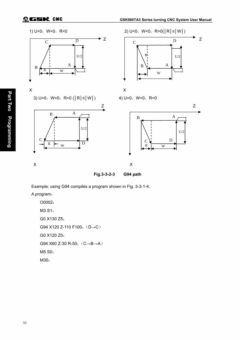
GSK980TA3 Series turning CNC System User Manual
50
Part Tw
oP
rog
ramm
ing
1) U<0,W<0,R<0 2) U<0,W<0,R>0(R≤W)
Z Z
X X
3) U>0,W<0,R>0 (R≤W) 4) U>0,W<0,R<0
Z Z
X X
Fig.3-3-2-3 G94 path
Example: using G94 compiles a program shown in Fig. 3-3-1-4.
A program:
O0002;
M3 S1;
G0 X130 Z5;
G94 X120 Z-110 F100;(D→C)
G0 X120 Z0;
G94 X60 Z-30 R-50;(C→B→A)
M5 S0;
M30;
U/2
R W
A B
C D
R U/2
W
A B
C D
U/2
R W D
C
B A
U/2
R W
D C
B A
Chapter Three Preparatory Function G Code
51
Part Tw
o P
rog
ramm
ing
3.3.3 Thread Cutting Cycle(G92)
Command format:
G92X(U)__ Z(W)__J__K__ F__ L__ P__; (metric thread)
Assign thread pitch(F)
G92X(U)__ Z(W)__ J__K__ I __ L__ P__;(inch thread)
Function:Executing G92 can machine the straight thread with constant pitch and the single cycle
thread machining of taper thread, the tool returns to the starting point after the cycle is
completed. The grooving is not demanded when thread cutting. When the user does not
use J, K to set length of thread run-out, the thread run-out length=set value set by P68
X0.1X pitch. In incremental programming, the sign of numerical value following U is
determined by X direction of path 1, that following W is done by Z direction of path 2.
Dotted lines in Fig. 3-3-3-1 and Fig. 3-3-3-2 means rapid traverse, real lines means
cutting feed. When J, K sets values, G92 executes X, Z thread run-out according to J, K
set value; when only J or K value is set, 45° thread run-out is executed.
Explanation:X.Z:coordinats of circular end point, unit:mm;
U.W:coordinates of circular end point corresponding to circular starting point,unit:mm;
J:proportion of X thread run-out, without sign. Unit:mm,J is the radius designation;
K:proportion of Z thread run-out,without sign. Unit:mm;
R:radius difference between thread starting point and end point,unit:mm;
F:metric thread pitch,range: 0.001~500,unit:mm,modal;
I: inch thread/inch tooth,range: 0.06~25400,unit:tooth/inch,modal;
L:number of thread head, range:(1~99),unit:head,modal;it is 1 when it is not
assigned;
P:length of thread run-out,range:(0~255),unit:0.1 pitch;
Assign thread pitch (tooth/inch)

GSK980TA3 Series turning CNC System User Manual
52
Part Tw
oP
rog
ramm
ing
Fig. 3-3-3-1
Fig. 3-3-3-2
Notes:
1. Notes of G92 are the same those of G32, refer to Section 3.2.14.
2. When there is the feed hold signal (pause) input in thread cutting cycle in the thread cutting cycle,
the cycle is executed till the operations of 3 completes to stop.
3. Thread pitch range, spindle speed limit are the same those of G32.
4. When using G92 machines the straight thread, start-up tool point and thread end point are the same
in X direction, the system alarms because the system cannot identify the inner thread or outer.
5. R value in G92 is referred to Fig. 3-3-1-3.
6. When one of J, K is set to 0,or is not assigned,the system takes it as 45° thread run-out.
7. I value can be input in MDI mode and cannot be displayed. Do not execute G92 in MDI mode.

Chapter Three Preparatory Function G Code
53
Part Tw
o P
rog
ramm
ing
Example: using G90 compiles a program shown in Fig. 3-3-3-3, and using G92 executes
machining thread.
Z
X
M60
x3
120
1 1 0
3 03 0
5
AB
CD
Fig. 3-3-3-3
A program:
O0001;
M3 S300;
G0 X150 Z50;
T0101; (outer turning)
G0 X130 Z5;
G90 X120 Z-110 F200; (C→D)
X60 Z-30;(A→B)
G0 X130 Z-30;
G90 X120 Z-80 R-30 F150;(B→C)
G0 X150 Z150;
T0202; (thread cutter)
G0 X65 Z5;
G92 X58.5 Z-25 F3; (machine thread,4 times cut-in)
X57.5 Z-25;
X56.5 Z-25;
X56 Z-25;
M5 S0;
M30;

GSK980TA3 Series turning CNC System User Manual
54
Part Tw
oP
rog
ramm
ing
3.3.4 Notes in Single Fixed Cycle Commands
1) In the single fixed cycle, X(U),Z(W),R are modal. When the new X(U),Z(W),R are
assigned,the previously commanded data are valid.
2) In the single fixed cycle, X(U),Z(W),R are cleared when the non modal G codes except
G04 or other commands except for G90, G92, or G94 in Group 01 are commanded.
3) When there is only blocks without movement codes after G90, G92, G94, the fixed cycle is
not executed repetitively.
(Example) N003 M3;
…
…
N010 G90 X20.0 Z10.0 F2000;
N011 M8;(do not repetitively execute G90)
…
…
4) In the fixed cycle, when M, S, T are commanded, the fixed cycle and M, S, T are
executed simultaneously. Cancel the fixed cycle after M, S, T is executed, execute it
again.
(Example) N003 T0101;
…
N010 G90 X20.0 Z10.0 F2000;
N011 G00 T0202;
N012 G90 X20.5 Z10.0;
3.4 Compound Fixed Cycle Commands
To simply programming, the system provides six compound cycle commands, including outer
(inner) roughing cycle G71; end roughing G72, closed cutting cycle G73/ finishing machining G70;
end deep hole machining cycle G74; outer grooving cycle G75 and compound thread cutting cycle
G76. The system only specifies tool cutting values of finishing and roughing, and automatically counts
machining paths and number of cutting.
3.4.1 Outer(Inner)Roughing Cycle(G71)
Command format:G71u(∆d)R(e);
G71 P(NS) Q(NF) U(∆u) W(∆w)F S T ;

Chapter Three Preparatory Function G Code
55
Part Tw
o P
rog
ramm
ing
N(NS) .....;
........;
....F;
....S; blocks for finishing path
....T;
·
N(NF).....;
Function: According to the workpiece’s finishing path, cutting amount, tool infeed and tool retraction
specified by the block, the system automatically count the roughing path, which is shown
in Fig.3-4-1-1. Cutting is executed by operations which are parallel to Z. The non forming
rod can be formed one time.
Explanation:∆d:cutting depth without sign at one time. The cut-in direction is determined by AA’
(specified by the radius), range: 0.001mm~9999.999mm. It is modal and valid before
the next is specified. It can be specified by P71, the parameter value also changes
according to the program command.
e: Tool retraction(specified by the radius),unit:mm,range: 0.001mm~9999.999mm.
It is modal and valid before the next is specified. It can be specified by P72, the
parameter value also changes according to the program command.
NS:It is the first block’s serial number in blocks for finishing path.
NF:It is the last block’s serial number in blocks for finishing path.
∆u:Distance and direction of X finishing allowance, range: -9999.999mm~9999.999mm.
∆w:Distance and direction of Z finishing allowance, range: -9999.999mm~9999.999mm.
F: Cutting feedrate, range: feed per minute is 1mm/min~8000mm/min, feed per rev is
0.001mm/r~500mm/r.
S: Spindle speed;
T: Tool, tool offset number;

GSK980TA3 Series turning CNC System User Manual
56
Part Tw
oP
rog
ramm
ing
Fig. 3-4-1-1 G71 path
1. d,u are specified by the same address U, and their difference is whether their blocks
specify P, Q.
2. The circular operations are executed G71 specified by P, Q.
3. In G71,F, S, T function in the blocks NS~NF are invalid and all are neglected. G71’s blocks
or the previous specified F, S, T are valid. F, S, T in the NS~NF are valid only to G70.
4. With the constant surface speed control selection function, G96 or G97 in the blocks NS~
NF is invalid, G71 or the previous blocks are valid.
5. According to the cut-in directions, G71 has four paths (Fig.3-4-1-2), which are executed
according to operations which are parallel, signs of ∆u.∆w are shown below:
A
A'
B U(-)..W(+)
A
A'
B U(-)..W(-)
A
A'
B U(+)..W(+)
A
A'
B U(+)..W(-)
Z
X
Linear,circular interpolation can be executed
Fig. 3-4-1-2

Chapter Three Preparatory Function G Code
57
Part Tw
o P
rog
ramm
ing
6. Only G00 or G01 is specified in the blocks which serial number is NS between A and A’, and
coordinates of A and A’ are consistent.
7. Between A' and B,X.Z values must monotonously increase or decrease, but their path
cannot be monotonous.
8. The system cannot call subprograms between NS and NF.
9. There are most 100 blocks between NS and NF, ERR137 alarm occurs when the blocks
exceed 100.
Example: Using G71 compiles a program shown in Fig.3-4-1-3.
S ta rt in g p o in t(2 0 0 , 1 0 )
1 0 06 0
4 0
8 0 1 0 2 0 3 0 3 0
ab
cd
e
2
0 .5
Z
X
Fig. 3-4-1-3
A porgram:
O0001;
N010 G0 X220.0 Z50; (positioning to safety position)
N020 M3 S300; (the spindle rotating CCW, speed 300r/min)
N030 M8; (cooling ON)
N040 T0101; (use a roughing tool )
N050 G00 X200.0 Z10.0; (rapid positioning,approach the workpiece)
N060 G71 U0.5 R0.5; (cut-in 1mm (diameter) at one time,tool retraction
1mm[diameter])

GSK980TA3 Series turning CNC System User Manual
58
Part Tw
oP
rog
ramm
ing
N070 G71 P080 Q120 U1 W2.0 F100 S200; (a---d roughing,X allowance 1mm,Z 2mm)
N080 G00 X40.0; (positioning to X40)
N090 G01 Z-30.0 F100 S200;(a→b)
N100 X60.0 W-30.0;(b→c) blocks for finishing path a→b→c→d→e
N110 W-20.0;(c→d)
N120 X100.0 W-10.0;(d→e)
N130 G00 X220.0 Z50.0; (execute rapid tool retraction to safety position)
N140 T0202; (use No. 2 finishing tool, execute No 2. tool offset)
N150 G00 X200.0 Z10.0; (positioning to the cycle starting point of G7)
N160 G70 P80 Q120; (finishing a--- e)
N170 M05 S0; (stop the spindle, speed)
N180 M09; (cooling OFF)
N190 G00 X220.0 Z50.0 T0100; (rapid return to safety position, use reference tool, clear tool
offset)
N200 M30; (end of program)
3.4.2 End Roughing Cycle(G72)
Command format:G72 W(∆d)R (e);
G72 P(NS) Q(NF)U(∆u)W(∆w)F S T ;
N(NS) .....;
.......;
.... F;
.... S; blocks for finishing path
.... T;
·
N(NF).....;
Function: According to the workpiece’s finishing path, cutting amount, tool infeed and tool retraction
specified by the block, the system automatically count the roughing path Cutting is executed
by operations which are parallel to X. The non forming rod can be formed one time.
Explanation:
∆d:cutting depth without sign at one time. The cut-in direction is determined by AB (specified
by the radius), range: 0.001mm~9999.999mm. It is modal and valid before the next is

Chapter Three Preparatory Function G Code
59
Part Tw
o P
rog
ramm
ing
specified. It can be specified by P71, the parameter value also changes according to the
program command
e: Tool retraction,unit:mm,range: 0.001mm~9999.999mm. It is modal and valid before
the next is specified. It can be specified by P72, the parameter value also changes
according to the program command.
NS:It is the first block’s serial number in blocks for finishing path.
NF:It is the last block’s serial number in blocks for finishing path.
∆u:Distance and direction of X finishing allowance,range: -9999.999mm~9999.999mm.
∆w: Distance and direction of Z finishing allowance,range: -9999.999mm~9999.999mm.
F:Cutting feedrate,range:feed/min : 1mm/min~8000mm/min,feed/r: 0.001mm/r~500mm/r.
S:Spindle speed;
T:Tool, tool offset number;
W
U/2
45ºE
A
D
Path specified by a program
Rapid traverse
Cutting feed
C
B
C´
A´B´
Fig. 3-4-2-1
Explanations:
1. d,u are specified by the same address W, and their difference is whether their blocks
specify by P, Q.
2. The circular operations are executed G72 specified by P, Q.
3. In G72,F, S, T function in the blocks NS~NF are invalid and all are neglected. G72’s blocks or
the previous specified F, S, T are valid. F, S, T in the NS~NF are valid only to G70.
4. With the constant surface speed control selection function, G96 or G97 in the blocks NS~NF
is invalid, G72 or the previous blocks are valid.
5. According to the cut-in directions, G72 has four paths (Fig.3-4-2-2), which are executed

GSK980TA3 Series turning CNC System User Manual
60
Part Tw
oP
rog
ramm
ing
according to operations which are parallel, signs of ∆u, ∆w are shown Fig.3-4-2-2.
6. Only G00 or G01 is specified in the blocks which serial number is NS between A and B, and
coordinates of A and B are consistent.
7. Between B and C,X.Z values must monotonously increase or decrease, but their path cannot
be monotonous.
8. The system cannot call subprograms between NS and NF.
9. There are most 100 blocks between NS and NF, ERR137 alarm occurs when the blocks
exceed 100.
U(-)..W(+)..
U(+)..W(+)..
U(-)..W(-)..
C C
U(+)..W(-)..
X
CC
Z
B A B
BA B A
A
Fig. 3-4-2-2 four shapes of G72 path
Example: using compound fixed cycle G72 compiles a program shown in Fig. 3-4-2-3.
16080
40
201520
X
Z
(176, 10)
d
b
a
cStarting point
Fig. 3-4-2-3

Chapter Three Preparatory Function G Code
61
Part Tw
o P
rog
ramm
ing
Program:
O0002;
N010 G0 X220.0 Z50.0;(position to safety position)
N015 T0202; (execute No. 2 tool,No. 2 tool offset)
N017 M03 S200; (the spindle rotating CCW,speed 200)
N020 G00 X176.0 Z10.0;(rapid positioning,approach the workpiece)
N030 G72 W2.0 R1.0; (tool infeed 2mm,tool retraction 1mm)
N040 G72 P050 Q090 U1.0 W1.0 F100 S200; (a—d roughing,X allowance 1mm,Z
allowance 1mm)
N050 G00 Z-55.0 S200 ;(rapid positioning)
N060 G01 X160.0 F120; (tool infeed to point a)
N070 X80.0 W20.0; (machining a—b) blocks for finishing path
N080 W15.0; (machining b—c)
N090 X40.0 W20.0 ; (machining c—d)
N100 G0 X220.0 Z50.0; (rapid tool retraction to safety position)
N105 T0303; (execute No. 3 tool, No. 3 tool offset)
N108 G00 X176.0 Z10.0; (rapid return G70)
N110 G70 P050 Q090; (finishing a—d)
N115 G0 X220.0 Z50.0; (traverse to safety position to execute tool change)
N120 M5 S0 T0200; (stop the spindle, execute No. 2 tool and cancel tool compentation)
N130 G0 X220.0 Z50.0; (rapid return to starting point)
N140 M30; (end of program)
3.4.3 Closed Cutting Cycle(G73)
Command format:G73u (∆i)W(∆k) R (d);
G73 P(NS)Q(NF)U(∆u)W(∆w)F S T ;
Function: G73 can execute the repetitive cutting along the path specified by the blocks NS~NF, the
tool moves forward once every cutting. For the smithing, casting and other roughing has
formed prelimiarily, which can improve the machining efficiency.
Explanation:∆i:distance and direction of X tool retraction (radius value), unit:mm; it is modal and
valid before the next is specified. It can be specified by P73, the parameter value
also changes according to the program command.
∆k:Distance and direction of Z tool retraction (radius value), unit:mm; it is modal and
valid before the next is specified. It can be specified by P74, the parameter value

GSK980TA3 Series turning CNC System User Manual
62
Part Tw
oP
rog
ramm
ing
also changes according to the program command.
D: Times of closed cutting, unit:times; it is modal and valid before the next is specified.
The parameter value also changes according to the program command, when set by
P75.
NS:It is the first block’s serial number in blocks for finishing path;
NF:It is the last block’s serial number in blocks for finishing path;
∆u:Distance and direction of X finishing allowance, range: -9999.999mm~9999.999mm.
the specified value is the radius or diameter value according to N0:1#3;
∆w:Z finishing allowance,range: -9999.999mm~9999.999mm;
F:Cutting feedrate,range: 1 mm/min~8000mm/min;
S:Spindle speed;
T:Tool, tool offset number;
AC
D
U/2
W
WK
Section from C to D is divided into(d-1)
i U/2
B
A’
Fig. 3-4-3-1 G73 path
1. F, S, T functions in any blocks between NS~NF are invalid. F, S, T functions only in G73 are valid.
2. ∆i,∆k,∆u,∆w are specified by the same address U, W, and their difference is whether their
blocks specify by P, Q.
3. The system cannot call subprograms between NS and NF in G73.
4. NS~NF blocks realize the cycle machining, signs of ∆u.∆w.∆i.∆k are paid more attention.
The tool returns to A after the cycle is completed.
5. When one of ∆i,∆k is 0, U0 or W0 is compiled in the course of programming; or P73/P74 are
set 0, otherwise, it is influenced by last G73’s set value.
6. There are most 100 blocks between NS and NF, ERR137 alarm occurs when the blocks
exceed 100.
Example Using 73 compiles programs shown in Fig.3-4-3-2.

Chapter Three Preparatory Function G Code
63
Part Tw
o P
rog
ramm
ing
X(200, 10)
Z
10 2010 40
Ø100
Ø140
Ø80
Ø160
2.5
2.5
Ø120
R10
1
Starting point
Fig. 3-4-3-2 G73 sample
A program is shown below:(the diameter is designed,metric input, ,least blank dimension is
Ø86)
N008 G0 X260.0 Z50.0 ; (positioning to safety position)
N009 T0101; (execute No. 1 tool, its tool offset)
N010 G98 M03 S300; (the spindle rotating CW,speed 300)
N011 G00 X200.0 Z10.0; (rapid position to starting point)
N012 G73 U2.0 W2.0 R3 ; (X tool retraction 4mm,Z tool retraction 2mm,roughing 3
times,diameter feeding 2mm at every tool infeed)
N013 G73 P014 Q020 U0.5 W0.5 F100 ;(X allowance 0.5mm,Z finishing allowance
0.5mm)
N014 G00 X80.0 W-10.0 S500 ;
N015 G01 W-20.0 F120 ;
N016 X100.0 W-10.0 ;
N017 W-30.0 ; blocks for finishing shape
N018 G02 X120 W-10.0 R10.0 F100 ;
N019 G01 X140.0 ;
N020 G01 X160.0 W-10.0 ;

GSK980TA3 Series turning CNC System User Manual
64
Part Tw
oP
rog
ramm
ing
N021 G0 X260.0 Z50.0; (traverse to safety position to execute tool change)
N022 T0303; (execute No. 3 tool, its tool offset)
N023 G00 X200.0 Z10.0; (rapid return to G70’s positioning)
N024 G70 P014 Q020; (finishing)
N025 M5 S0 T0200; (stop the spindle,execute No. 2 tool and cancel its tool
compensation)
N026 G0 X260.0 Z50.0; (rapid return to starting point)
N027 M30; (end of program)
3.4.4 Finishing Cycle(G70)
Command format:G70 P(NS)Q(NF);
Function:when G70 is executed, the tool executes the finishing along the workpiece finishing path
specified by NS~NF from the initial point.
Using G70 executes finishing after G71, G72, G73 executes roughing.
Explanation:NS: It is the first block’s serial number in blocks for finishing path;
NF: It is the last block’s serial number in blocks for finishing path.
G70 path is determined by NS~NF blocks. Relative position of NS, NF in G70~G73 is
shown below:
........
........
G71/G72/G73 P(NS) Q(NF) U(∆u) W(∆w) F S T ;
N(NS) ......
........
· F
· S
· T
·
·
·
N(NF)......
·
G70 P(NS) Q(NF);
·
1. F, S, T function among “NS” and “NF” in G71 G72 G73 are invalid, but they are valid in G70.

Chapter Three Preparatory Function G Code
65
Part Tw
o P
rog
ramm
ing
2. The tool returns to starting point and the system reads the next block when G70 completes.
3. G70 includes S, T, F. In M code, M30 is valid when M30 and G70 are in the same block, and it
is invalid when it and other commands are in the same block.
4. Blocks between NS and NF in G70 cannot call subprograms.
Example:See G71.G72 sample.
5. The address specified by P.Q should be single and cannot be repetitively commanded. When
a program defines the same serial number, the system runs the block for finishing neighboring
G70.
3.4.5 End Deep Hole Machining Cycle(G74)
Command format:G74 R(e);
G74 X(U)Z(W)P(∆i)Q(∆k)R(∆d)F;
Function: When G75 is executed, the system confirms the cutting end point according to blocks (the
point confirmed by X, Z coordinates) e.∆i.∆k and ∆d confirms the tool path. In the cycle, it
can execute the chip breaking of end cutting. When X (U) are omitted, only Z is executed,
which is the deep hole machining. G74 path is shown in Fig. 3-4-5-1.
Explanation:e:Tool retraction amount after cutting ∆k along Z, unit:mm,range: 0.001mm~
9999.999mm. It is modal and valid before the next is specified. It can be specified
by P76, the parameter value also changes according to the program command.
X: X absolute coordinate value of cutting end point B2, unit:mm;
U: Difference of X absolute coordinate between cutting end point B2 and starting point A,
unit:mm;
Z: Z absolute coordinate value of cutting end point B2, unit:mm;
W:Difference of Z absolute coordinate between cutting end point B2 and starting point A,
unit:mm;
∆i: X circular movement at one time(without sign, radius value), unit:mm;
∆k:Z cutting movement at one time(without sign),unit:mm;
∆d:X tool retraction when cutting to end point(radius value),unit:mm;
F: Cutting feedrate. Range: feed per minute is 1mm/min~8000mm/min,feed per rev is
0.001mm/r~500mm/r”.

GSK980TA3 Series turning CNC System User Manual
66
Part Tw
oP
rog
ramm
ing
e
ΔK
Δd
Δi
U/2
W
rapid traverse
cutting feed
AB
C D
A:starting point of axial cutting cycle
B: end point of axial feed
C: end point of radial tool retraction
D: end point of axial cutting cycle
0<Δi’≤Δi
0<ΔK’≤ΔK
ΔK+eΔK’
A1
D1C1
B1
A2
D2C2
B2
Δi'
Z
X
X/2
Z
Fig. 3-4-5-1
1. e and ∆d are specified by the address R, and their difference are whether they are specified
by Z(W),namely, when X(U)is commanded, it is ∆d,when X(U)is commanded, it is e;
2. When the cycle operation include G74 of Z(W)and Q(k), “G74 R(e)” is executed, the
cycle operation cannot be executed.
Example: Using G74 compiles a program shown Fig. 3-4-5-2.
X
Ø60
20
Ø20
Ø40
80
Z
Fig. 3-4-5-2
A program:
O0001; (program name)
G0 X100 Z50; (rapid positioning )

Chapter Three Preparatory Function G Code
67
Part Tw
o P
rog
ramm
ing
T0101; (tool width 2mm)
M3 S500 G97; (start the spindle,its speed 500)
G0 X36 Z5; (positioning to starting point of machining, tool width having been
added to X value)
G74 R1 ; (Z tool retraction)
G74 X20 Z-20 P2 Q3.5 F50;(X cycle movement 4mm at one time 4mm,Z 3.5mm)
G0 Z50; (Z tool retraction)
X100; (X tool retraction)
M5 S0; (stop the spindle)
M30; (end of program)
3.4.6 Outer Grooving Cycle(G75)
Command format:G75 R(e);
G75 X(U) Z(W) P(∆i)Q(∆k)R(∆d)F ;
Function: When G75 is executed, the system confirms the cutting end point according to blocks (the
point confirmed by X, Z coordinates) e.∆i.∆k and ∆d confirms the tool path. It is similar that
X, Z are exchanged in G74, and in the cycle, it can execute the chip breaking of end
cutting, execute the grooving and cutting-down machining of outer diameter(omit Z, W, Q).
G75 path is shown in Fig. 3-4-6-1.
Explanation: e: Tool retraction amount after cutting ∆i along X, unit:mm,range: 0~9999.999mm.
It is modal and valid before the next is specified. It can be specified by P76, the
parameter value also changes according to the program command;
X: X absolute coordinate value of cutting end point B2,unit:mm;
U: Difference value of X absolute coordinate between cutting end point B2 and A,unit:
mm;
Z: Z absolute coordinate value of cutting end point B2,unit:mm;
W: Difference value of Z absolute coordinate between cutting end point B2 and A, unit:
mm;
∆i:X circular movement at one time(without sign, radius value),unit:mm;
∆k:Z cutting amount at one time(without sign),unit:mm;
∆d:Z tool retraction amount when cutting to end point,unit:mm;
F :Cutting feedrate.
G74, G75 are used to cutting, grooving or hole machining, make the tool automatically
retract.

GSK980TA3 Series turning CNC System User Manual
68
Part Tw
oP
rog
ramm
ing
Fig. 3-4-6-1
1. e and ∆d are specified by the address R, and their difference are whether they are
specified by X(U),namely, when X(U)is commanded, it is ∆d,when X(U)is
commanded, it is e;
2. The circular operations is executed by G75 specified by X (U).
Example: Using G75 compiles a program shown in Fig. 3-4-6-2.
Ø120Ø120
Ø40
20
5080
Z
X
Fig. 3-4-6-2 G75 sample
A program:
O0001; (program name)

Chapter Three Preparatory Function G Code
69
Part Tw
o P
rog
ramm
ing
G0 X150 Z50; (rapid positioning)
T0101; (too width 4mm)
M3 S500 G97; (start the spindle,its speed 500)
G0 X125 Z-24; (positioning to starting point of machining, the tool width having
been added to Z)
G75 R1 ; (X tool retraction)
G75 X40 Z-50 P2 Q3.5 F50;(X cycle movement 4mm at one time 4mm,Z 3.5mm)
G0 X150; (X tool retraction)
Z50; (Z tool retraction)
M5 S0; (stop the spindle)
M30; (end of program)
3.4.7 Compound Thread Cutting Cycle(G76)
Command format:G76 P(m)(r)(a)Q(dmin) R(d);
G76 X(U) Z(W) R(i)P(k)Q(d)F(I) ;
Function:The system automatically counts and executes thread cutting cycle many times according
to the commanded address, and G76 path is shown in Fig. 3-4-7-1.
Explanation:X.Z: coordinates of thread end point (bottom of thread),unit:mm;
U.W:coordinates of thread end point corresponding to machining starting point,unit:
mm;
m:it is repetitive times of last finishing, modal, valid before it is specified next time. It is
set by P77, the parameter value is also changed according to the commands. Range:
1~99;
r: Chamfer value of thread. When L is the lead, in 0.1L~9.9L, 0.1L is taken as the first
gear, using 00~99 two numerical values is specified. It is modal and valid before it is
specified next time. Using P68 also change the parameter value according to the
commands. After G76 set the thread chamfering value, it influences in G92 thread
cutting cycle.
a:Tool nose angle(angle of thread tooth can select the angle 80°,60°,55°,30°,29°,
0°).
The original of angle value is specified by two numerical value. It is modal, and valid
before it is specified next time. It is set by P78, and the parameter value is changed
according to the command. The tool nose angle can select 80°.60°.55°.30°.29°.0°;

GSK980TA3 Series turning CNC System User Manual
70
Part Tw
oP
rog
ramm
ing
dmin : least cut-in value, unit : mm. When the first cut-in value
(D× N -D× 1N ) is less than dmin, dmin is taken as the first cut-in
value. It is modal, and valid before it is specified next time. It is also set by P79, the
parameter value can be changed by the commands. The least cut-in value is 0~
9999999,unit:0.001mm;
d:Finishing allowance, unit:mm. It is modal, and valid before it is specified next time. It is
set by P80, the parameter value is changed by the command. The finishing allowance
range is 0~9999999, unit:0.001mm;
i: Radius difference of thread part, unit:mm,i=0 : cutting the straight thread;
k:Tooth height of thread(X distance is commanded by the radius value), unit: mm;
d:The first cutting depth, radius value, unit:mm.
F:Thread lead, unit:mm;
I:Tooth/inch.
Z
X/2
U/2
W
A
B
ED
C
Z
X
Fig. 3-4-7-1
Cut-in method is shown in Fig. 3-4-7-2:
Fig. 3-4-7-2

Chapter Three Preparatory Function G Code
71
Part Tw
o P
rog
ramm
ing
1. Data specified by P, Q, R are distinguished by whether they have X (U), Z (W) or not.
2. The cycle operation is executed by G76 specified by the address X(U),Z(W).
3. In cycle machining, the tool uses the one-side to machine, and the tool nose load can be
reduced.
4. The first cut-in amount is d,the N times cut-in is D× N ,each cut-in amount is fixed.
5. There are four machining shapes, which can machine inside thread. B, C section uses the
feedrate commanded by F, others are rapid traverse in Fig. 3-4-7-1.
Increment signs are determined as follows:
U:It is determined by the direction from the path A to C;
W:It is determined by the direction from the path C to D;
R(I):It is determined by the direction from the path A to C;
P(K):positive;
Q(D):positive.
6. Its notes are the same those of G32.
7. The thread chamfering value designation is valid to G92 thread cutting cycle.
8. m,r,a are specified by the address p one time.
Example: using G76 compile a program shown in Fig. 3-4-7-3, machining thread is M68X6.
6
60.64
68
62
Fig. 3-4-7-3
A program:
G00 X100 Z50; (positioning to safety position)
M03 S300; (start the spindle, specify its speed)
G00 X80 Z10; (rapid positioning to starting point of machining)
G76 P011060 Q0.1 R0.2; (execute thread cutting)
G76 X60.64 Z-62 P3.68 Q1.8 F6.0;
G00 X100 Z50; (return to starting point of the program)
M5 S0; (stop the spindle)
M30; (end of program)
Cutting point zoom in

GSK980TA3 Series turning CNC System User Manual
72
Part Tw
oP
rog
ramm
ing
3.4.8 Notes of Compound Fixed Cycle Codes
1. There must be P,Q,X,Z,U,W,R in blocks of the commanded compound fixed cycle, each
block must be commanded correctly.
2. In blocks of G71, G72, G73, when their serial numbers are specified by P, the blocks of
corresponding serial number must command G00 or G01 in Group 01, otherwise, P/S alarm
occurs.
3. In MDI mode, the system cannot execute G70,G71,G72,G73,G74,G75,G76. Namely,
they cannot be executed even if they are commanded.
4. In G70,G71,G72,G73, the blocks which serial numbers are specified by P and Q cannot have
the followinG Codes:
Codes in Group 01 except for G00, G01, G02, G03;
M98/M99;
G04 is valid in the last forming tool of roughing and valid in finishing.
5. When the compound fixed cycle (G70~G76)is executed, the operation can be stopped to
insert the
manual operation, but the system must return the previous operation before the compound
fixed cycle
is executed again. If not, the manual movement amount will not be added to the absolute value,
the
following operation will miss position, which value is equal to manual movement amount.
6. When G70,G71,G72,G73 is executed,the serial numbers specified by P,Q cannot be
repetitive in the program.
7. Notes of G76 are same those of G32, G92, are valid for thread chamfering designation and
G92.

Chapter Four Miscellaneous Function M Codes
73
Part Tw
o P
rog
ramm
ing
CHAPTER FOUR MISCELLANEOUS FUNCTION M CODE
The movement command and M code must be executed simultaneously when they are in the
same block.
(Example ) N1 G01 X50.0 Z-50.0 M05 ;(spindle stop)
4.1 Miscellaneous Function (M function)
Miscellaneous function M code consisted of the address M and two-digit numerical value. The
system sends the corresponding control signal to the machine, used to control the corresponding
function ON/OFF of the machine. There must be only one M code in the same block.
The system supports the following M codes:
M03 : Spindle rotation CW.
M04 : Spindle rotation CCW.
M05 : Spindle stop.
M08 : Cooling ON.
M09 : Cooling OFF(do not output signals).
M10 : Tailstock forward.
M11 : Tailstock backward.
M12 : Chuck clamping.
M13 : Chuck releasing.
M32 : Lubricating ON.
M33 : Lubricating OFF(do not output signals).
M00 : Program pause; press ‘Cycle Start’ key to continuously execute programs.
M30 : End of program; the program returns to the initial.
M41~M44 :Automatic gear-change function of spindle(see Machine Connection Section,
Automatic Gear-Change Control of Spindle)
M51~M70 :User-customized output control
M91~M94 :User-customized input control
Except for M00, M30, execution time (not pulse width) of other M codes is set by P86.
Set value:0~9999999
Set time =set value ×4 ms.

GSK980TA3 Series turning CNC System User Manual
74
Part Tw
oP
rog
ramm
ing
Fig. 4-1-1
Note 1: When other M codes except for the above, the system alarms the following and stops the
execution.
NO.181: M code is wrong, illegal M codes are input into the program.
Note 2: After M, S, T, function is activated, the mode still remains even if it is changed, ‘Reset’ key is
pressed to close the activation. (NO:12#0 sets whether M, S, T function is valid.)
The following M codes describe special usages:
1. M30 end of program
1) M30 means the end of main program.
2) It means the system stops the automatic run, is in reset state.
3) It means the system returns to the beginning of the main program.
4) It means 1 is added to the number of machining workpiece.
2.M00:Program pause
After the block of M00 is executed, the system stops the automatic run. It is the same
that of the single block stop, and the system saves the previous modal information. The
system starts the automatic run after it runs.
3. M98/M99 (call subprogram/ subprogram return)
Format:
Called subprogram number(0000-9999)
Times of call(1-999)
PM98
It can be execute repetitively when it is used for calling a subprogram or the end of
program is M99. The four-embedding of subprogram can be executed and is referred to
Section 4.7 Subprogram Control.
Note 1: The next block of M00, M30 cannot be saved into the buffer storage even if it exists.
Note 2: The code signals are not output when M98, M99 is executed.

Chapter Four Miscellaneous Function M Codes
75
Part Tw
o P
rog
ramm
ing
4.2 Special M Codes(M21.M22.M23.M24 )
Relevant Parameters:
M21 =0:The corresponding output pin does not execute the output
=1:The corresponding output pin executes the output
M23 =0:The corresponding output pin does not execute the output
=1:The corresponding output pin executes the output
Input/output signals:
M21I :input signal(user-customized input pin) M21O:output signal(user-customized output pin)
M23I :input signal(user-customized input pin) M23O:output signal(user-customized output pin)
Use method:
Function 1: M21 When M21=0, the corresponding output pin does not execute the output; when
M21=1, it outputs M21O.
Example:G0 X100 Z100
M21 execute the normal M code
G0 X0 Z0
M22 close output M21O
M30
Function 2:M21 P when M21 is set 1 and after M21 P function is executed in the time specified by
P, M21 output ends.
Example:G0 X100 Z100
M21 P10000 the duration of M21 execution is 10s, and M21O is closed.
G0 X0 Z0
M22
M30
Function 3: M21Q When M21 is set 1 and M21 Q function is executed, the corresponding output pin
has the output signal and waits for the input signal, and there is an input signal, the
system waits for the end to execute the next block; when there is no input signal, the
system always waits.
Example:G0 X100 Z100
M21 Q1 the system checks input interface M21I,and waits always without it.
G0 X0 Z0
M23 M21 0 1 3

GSK980TA3 Series turning CNC System User Manual
76
Part Tw
oP
rog
ramm
ing
M22
M30
M22 close the output M21O.
Note 1: The time unit is ms when P is specified.
Note 2: When Q is specified, its numerical value is not 0, it is HIGH, otherwise, it is LOW.
Note 3: M23 use methods are the same those of M21; M24 of M22.
4.3 M Code Calling Subprograms
When NO.4#2(CM98) is set to 1 and the system executes others except for M, S, T, the system
calls a corresponding subprogram instead of alarm. The user can extend miscellaneous function
codes according to requirements combined with macro input/output interface variable.
M code: when the system executes others except for standard codes, the called subprograms
are :
M:called subprogram 90.
4.4 S Codes Calling Subprograms
When NO.4#2(CM98) is set to 1 and the system executes others except for M, S, T, the system
calls a corresponding subprogram instead of alarm. The user can extend miscellaneous function
codes according to requirements combined with macro input/output interface variable
S code: when the system executes S10~S99, the called subprograms are:
S:called subprogram 91.
Note 1: S codes cannot call subprograms when the spindle analog voltage output is selected.
Note 2: When the system executes the non-standard M, S, the corresponding subprograms must be input
otherwise, NO.78 alarm occurs.
Note 3: The non-standard M, S, T codes cannot run in MDI mode, otherwise, M/S or T code wrongly alarms
or NO.130 alarm occurs.
Note 4: In the corresponding subprogram, the axis motion command can be input, or the output point can
be controlled (ON/OFF), or the skip or cycle is executed, some DI signal is taken as an end signal
of M/S/T. See Macro Program about DI/DO.
4.5 T Codes Calling Subprograms
When NO.4#2(CM98) is set to 1 and the system executes others except for M, S, T, the system
calls a corresponding subprogram instead of alarm. The user can extend miscellaneous function
codes according to requirements combined with macro input/output interface variable.

Chapter Four Miscellaneous Function M Codes
77
Part Tw
o P
rog
ramm
ing
T code: when the system executes others except for standard codes, the called subprograms
are :
T:called subprogram 92.
For example: T28 calls the subprogram 9228.
4.6 Parameters of Miscellaneous Function
The parameters are set by the user according to the actual.
Setting: Open the parameter protection switch, select the parameter window in MDI mode, move
cursor to the front of the required serial number to input data, press and then the
data is input into the corresponding parameters.
Methods for searching a serial number are shown below:
1) Use Page Up/Down to find out the serial number window, move the cursor by the
direction key to position to the required serial number position.
2) Search method: press →input the required searched parameter number
→press .
4.7 Alarm Related to Miscellaneous Function
Alarms related to miscellaneous function are displayed on the external message window. When
the system alarms, it automatically switches to external message window, and the detailed contents
of alarm are displayed on the top of LCD, ‘ALARM’ flashed at the right of LCD.
181:M code error.
Illegal M codes are input into the program.
182:S code error.
Illegal S codes are input into the program.
183:T code error.
Illegal T codes are input into the program.
185:The tool change time is too long.
The system alarms when it has not received the specified cutter spacing arrival signal after the
time of the tool post rotating forward for Ta .
186:The system has not received the tool post’s reverse locking signal within the tool post
reverse locking time.

GSK980TA3 Series turning CNC System User Manual
78
Part Tw
oP
rog
ramm
ing
187 :Tool change is not ready.
The system does not check whether the tool number is consistent with the current tool number.
044:Start the spindle when the chuck clamps.
045:The chuck releases when the spindle runs.
250:The tailstock advancing/retreating is executed Automatic run, starting the spindle, the
spindle rotating.

Chapter Four Miscellaneous Function M Codes
79
Part Tw
o P
rog
ramm
ing

GSK980TA3 Series turning CNC System User Manual
80
Part Tw
oP
rog
ramm
ing
CHAPTER FIVE SPINDLE FUNCTION S CODE
The code signal is sent to machine by the address S and its following numerical value, used to
control the spindle of the machine. In a block, one S code can be commanded.
Refer to the manufacturer’s user manual about digits and use of S code.
When the movement command and S code are in the same block, they are executed
simultaneously.
5.1 Spindle Switching Value Control
NO:1#4=0: the address S and its following numerical value control the spindle’s speed.
Command format: S__
The system provides 4-gear spindle mechanic gear change. Refer to the manufacturer’s user
manual about the corresponding relation between S code and the spindle speed, and the spindle
speed gear of the machine (without selecting the analog spindle function).
Gear signal: S1~S4
Duration of S code is set by P87.
Set value:0~9999999
Set time = set value ×4 ms.
Fig. 5-1-1
Note: The system alarms below and stops the operation when the program specifies others except for the
above S codes.
182:S code error, illegal S code is input to the program.
5.2 Spindle Analog Value Control
NO:1#4=1: the address S and its following numerical value directly commands the rotation
quantity of the spindle (r/min), the unit of quantity of the spindle is different because of the different
machine manufacturer. P55~P58 sets the max. speed of the spindle.
Command format: S__

Chapter Five Spindle Function S code
81
The system realizes the spindle stepless speed regulating when the spindle analog value control
is activated.

GSK980TA3 Series turning CNC System User Manual
82
Part Tw
oP
rog
ramm
ing
CHAPTER SIX TOOL FUNCTION T CODE
Use the address T and its following 2-digit numerical value to select the tool installed on the
machine. In one block, the system can command a T code. They are executed simultaneously when
the movement command and T code are in the same block.
Refer to the machine manufacturer’s user manual about T code use.
Use T code and its following numerical value to select the tool. The following two-digit numerical
vaue are used for specifying the compensation number of the tool compensation.
Tool selection number
T
Tool compensation number
The tool quantity provided by the system is set by P81, and its most setting is 8.
6.1 Tool change Process
Fig. 6-1-1
In the above figure, P83 setting corresponds to the time parameter set by the parameter
number.
When Ta≥P8 × quantity of tool change, NO.185 alarm occurs: the tool change time is too
long. The system alarms when it has not received the specified tool arrival signal after the time
of the tool post rotating forward for Ta .
When Ta≥P85 × quantity of tool change, NO.186 alarm occurs: the tool change time is too
long. The system alarms when it has not received the specified tool arrival signal after the time
of the tool post rotating reversely.

Chapter Six Tool Function T Code
83
Part Tw
o P
rog
ramm
ing
When T code is executed, the system output the tool post rotation (forward rotation signal)
(TL+), and after it has received the tool arrival signal specified by T code, closes the signal and
delays T1, then the tool post starts the reverse rotation to lock (TL-) and checks the locking
signal *TCP; and after it has received the locking signal, delay the time set by P85, closes the
reverse signal (TL-). When the executed tool number and the current tool number (it is recorded
automatically in P49), the tool change command stops and the system executes the next block,
otherwise, NO.187 alarm occurs.
After the system outputs the tool post’s reverse rotation signal, has not received *TCP
signal in the time set by P88, it alarms and closes the rotation signal.
Note: When the tool post mask position offsets, NO.187 alarm occurs after tool change, at the moment,
the user should regulate the mask position or set No.10 BIT3 to 0.
6.2 Relevant Parameters of Tool Change
1) System parameters
The tool post in-position signal (*T8~*T1)HIGH or LOW is set by NO:9#1 TSGN.
TSGN 0 : the tool post in-position signal HIGH is valid.(normally-closed)
1 : the tool post in-position signal LOW is valid. (normal open)
The tool post locking signal (* TCP)HIGH or LOW is set by NO:9#0 TCPS.
TCPS 0 : the tool post locking signal LOW is valid.(normal open)
1 : the tool post locking signal HIGH is valid.(normally-closed)
Note: When there is no tool post locking signal, it cannot be connected, it is valid when TCPS
is LOW, P085 sets the reverse locking time. 980TA3 has no the signal *TCP, and TCPS is
set to “0”.
2) Relevant parameters of tool post
T1 : delay time from the tool post stopping forward to starting reversely rotation.
P82,set value: 0~9999999 unit:4ms
Ttool quantity : tool quantity of tool post.
P81, set value 1~8 unit:piece.
T2 :delay time after receiving locking signal of tool post reversely rotation.
P85, set value 0~9999999 unit:4ms
Tone tool:the maximum time of tool change.
P83, set value 0~9999999 unit:4ms
T total tools:the maximum time from the first to the last tool change.
P84,set value 0~9999999 unit:4ms

GSK980TA3 Series turning CNC System User Manual
84
Part Tw
oP
rog
ramm
ing
3) Diagnosis parameters
Tcurrent tool number:current tool number.
The diagnosis number P49. The system automatically sets its value, namely, the
manual tool change is executed, i.e. automatic setting when the value is used firstly or
the storage is cleared.
Ta :The system automatically count the required maximum time from current tool change to
the specified tool.
Ta = T tool×tool quantity of tool change.
Example: Supposing that the total tool quantity is 6.
a)The current tool is 1,the specified is 5,the tool of tool change is 4.
b)The current tool is 5,the specified is 2,the tool of tool change is 3.
Tb : The longest time signal for having received the tool post reverse rotation signal
6.3 Tool Offset
In the actual machining, the reference tool in programming is not almost consistent with the actual
machining tool, at the moment, the difference between the standard position and atucal tool nose is
called offset value.
The tool offset is controlled by T code instead of G code.
6.3.1 Basic Tool Offset
Fig. 6-3-1-1
The offset result makes the tool nose of the standard tool move in the programmed path, the tool
installation is consistent with the initial point of standard tool in program, but the actual machining
tool is not almost consistent with the standard. The difference between the standard position and

Chapter Six Tool Function T Code
85
Part Tw
o P
rog
ramm
ing
the actual tool nose position is called offset value.
6.3.2 T Code for tool offset
T code’s meanings:
a) Tool selection
The tool selection is executed by specifying T code corresponded to the tool number.
Refer to the machine manufacturer’s user manual about relationship between the tool
selection number and the tool
b) Tool offset number
It is used for selecting the offset value corresponded to the offset number. The offset value
must be input by keyboard. The corresponding offset number has two offset values, one for
X and another for Z. See Tool Compensation Display, Modification and Setting about its
concrete operations.
Table 6-3-2-1
Offset value
Offset number X offset value Z offset value
01
02
03
..
..
..
0.040
0.060
0
.
.
.
0.020
0.030
0
.
.
.
The tool offset is valid when T code is specified and its offset number is not 00.
When the offset number is 00, the tool offset function is cancelled.
Offset value is set:
Input in mm: -9999.999 mm~9999.999mm
NO:2#5 ORC can specify the diameter/radius specifications to X tool offset value.
6.3.3 Offset
Offset X, Z is for programmed path. T code specifies the offset value of offset number, and the offset

GSK980TA3 Series turning CNC System User Manual
86
Part Tw
oP
rog
ramm
ing
value is added or subtracted at the end point of each block.
Fig. 6-3-3-1
a)Offset vector
In above figure, X, Z vector with offset is called offset vector. The compensation affects the
offset vector.
b)Offset cancellation
When the offset number of T code selects 00, the offset is cancelled. The offset vector is 0 at
the end of canceling blocks.
N1 G01 U50.0 W100.0 T0202;
N2 W100.0:
N3 U0.0 W50.0 T0200;
Offset path
Fig. 6-3-3-2

Chapter Six Tool Function T Code
87
Part Tw
o P
rog
ramm
ing
6.3.4 Programming Example
Tool nose offset(Z,X) tool number
Tool #1……B(0.120,0.200) 01
Tool #2……C(-0.180,-0.050) 02
Fig. 6-3-4-1 tool compensation example- 2
(Program example 1)
G00 X280.0 Z240.0;
G00 X120.0 Z200.0 T0101;
G01 Z140.0 F30;
X160.0 Z80.0;
G03 X227.7 Z30.0 R53.81;
G00 X280.0 T0100;
#1 tool nose path is the same that of the programmed of the program.
(Program example 2)
Modifying example 1, #2 tool nose path is the same that of the programmed.
T0101→T0202 and T0100→T0200
6.3.5 Single T code
When T code and the movement function command are in the same block, the traverse speed to
execute the tool length compensation is decided by the movement command to cutting feedrate or
rapid traverse speed.
No.1 tool offset value path
No.2 tool offset value path

GSK980TA3 Series turning CNC System User Manual
88
Part Tw
oP
rog
ramm
ing
NO:2#0=0: when a single T code is executed, the speed of tool length compensation is
determined by the current mode: when the current mode is the cutting feed, the tool length
compensation is executed at the current cutting federate; when the current mode is G00, it is done at
the current rapid traverse speed.
NO:2#0=1: when a single T code is executed, the tool length compensation and the first
subsequent movement command are executed simultaneously, the speed of the tool length
compensation is determined by the movement command.

Chapter Six Tool Function T Code
89
Part Tw
o P
rog
ramm
ing

GSK980TA3 Series turning CNC System User Manual
90
Part Tw
oP
rog
ramm
ing
CHAPTER SEVEN USER MACRO PROGRAM
A group of command for realizing some function is saved to storage in advance like
subprograms, one command standing for these functions is used. Only the command input in
programs can realize these function. The group is called user macro program body, the command is
called ‘user macro command’. The user macro program body is called macro program sometime.
The user macro code is also called macro program call command.
Fig. 7-1
The programmer need not remember macro program body, but does user macro codes as
commands.
Obvious features of user macro programs the variable can be used in user macro program body.
The variables can be operated and macro code is assigned.
7.1 User Macro Code
The user macro code is a command to call user macro program body.
Command format:
Using the above command can call macro program body specified by P.
7.2 User Macro Program Body
The user macro program body can use generally CNC command, or use variable, operation or
transfer command.
User macro program body begins with a program number following O and ends with M99.

Chapter Seven User Macro Program
91
Part Tw
o P
rog
ramm
ing
1) Variable usage
Variables can command the address values in user macro program body. The variable value is
assigned by a main program or set by key board, or is assigned when the user macro program
body is executed.
Use many variables, and they can be distinguished by their variable numbers.
a)Variable meaning
The variable number with # means the measurement, and its format is shown below:
#(i=200,202,203,204……)
(Example) #205,#209,#1005
b)Variable reference
Using variable can replace the numerical value following the address.
When a program has “﹤Address﹥# i” or ”﹤Address﹥-# i”,it means to take the variable value or the
negative of the variable value as the address value.
(Example)F#203…#203=15: it is the same as F15.
Z-#210…#210=250: it is the same as Z-250.
G#230…#230=3: it is the same as G3.
Variable replacing its variable number can describe into ##9200 instead of ##9200, “9” following #
means the replacement variable number.
The following examples are to displace the variable number.
(Example #200 = 205,#205 = 500:
X#200 and X500 are the same.
X-#200 and X-500 are the same.
Note 1: O and N cannot reference variables, and cannot use O#200,N#220 in programming.
Note 2: When the variable exceeds the maximum programmable dimension described by the address, it
cannot be used. When #230 = 120, M#230 exceeds its maximum programmable dimension.
Note 3: Display and setting of variable value: it can be displayed on LCD window, and can be set by press
key.

GSK980TA3 Series turning CNC System User Manual
92
Part Tw
oP
rog
ramm
ing
2)Variable classification
The variable is divided into the common and system according to the variable number, and their
use and properties are different.
a)Common variable #200~#231
The common variable is common in main programs or user macro programs called by main
programs. Namely, variable # i used in some user macro program and # i used in other
macro programs are the same. So, the common variable #i of operation result in some
macro program can be used to other macro programs.
The common variable use is defined by the user.
Common variable #200~#231 are all “0” when the power supply is turned on again, after
the power supply is turned on again.
b)Common variable #500~#515
The variable use is the same those of #200~#231. After the power supply is tuned off,
the variable data is saved, and remains when power-on again.
c)System variable #1000~#1031
The variable use is fixed in the system.
Interface input signals #1000~#1031(select the function- need to match corresponding
selected parts).
After the system reads the system variable #1000~#1031 values as the interface signals, it can
learn states of interface input signals.
Tool No.:
7 6 5 4 3 2 1 0
TCP DIQP *DECX DITW *SP *ST *DECZ *ESP
#1007
XS39:12
#1006
XS39:11
#1005
XS40:1
#1004
XS40:
2
#1003
XS40:7
#1002
XS40:
8
#1001
XS40:
9
#1000
XS40:10
T08 T07 T06 T05 T04 T03 T02 T01
#1015
XS40:19
#1014
XS40:20
#1013
XS40:21
#1012
XS40:22
#1011
XS40:
3
#1010
XS40:
4
#1009
XS40:
5
#1008
XS40:6
SAR LTZ LTX SPEN PCH DOOR GR2 GR1
Programmed variable number
Pin
001
Diagnosis No.

Chapter Seven User Macro Program
93
Part Tw
o P
rog
ramm
ing
Value of 32-digit DI signal is automatically assigned to macro variable (#1000~#1031)inside
the system. It with other logic judge, skip macro code are used together to perform various of
execution.
#1000~1031 are values of corresponding points (0/1).
Interface output signal #1100~1131 (select the function- need to match corresponding selected
parts).
Assign the system variable #1100~1131 to change state of output signals.
Bit No:
7 6 5 4 3 2 1 0
SPZD DOQPJ M05 M32 M08 M10 M04 M03
#1107
XS40 :
17
#1106
XS40:4
#1105
XS39 :
16
#1104
XS39:
6
#1103
XS39 :
15
#1102
XS39:
2
#1101
XS39:
3
#1100
XS39:7
TL- TL+ DOQPS M11 M44 M43 M42 M41
#1115
XS40:13
#1114
XS40:12
#1113
XS39:10
#1112
XS39:
9
#1111
XS39:
8
#1110
XS39:14
#1109
XS39:
1
#1108
XS39:5
M53 M51 TLC STAR TRIAN WAR M30 MST
#1123
XS42:17
#1122
XS42:4
#1121
XS42:16
#1120
XS42:15
#1119
XS42:
3
#1118
XS42:
2
#1117
XS42:14
#1116
XS42:
1
#1023
XS41:7
#1022
XS41:19
#1021
XS41:6
#1020
XS41:
5
#1019
XS41:
4
#1018
XS41:3
#1017
XS41:
2
#1016
XS41:1
M01 M93 M91 LTY DECY LCK OWA2 OWA1
#1031
XS42:12
#1030
XS42:11
#1029
XS41 :
10
#1028
XS41:22
#1027
XS41:
9
#1026
XS41:21
#1025
XS41:
8
#1024
XS41:20
003
004
005
Macro program Programmed variable No.
Pin
Diagnosis No.
006

GSK980TA3 Series turning CNC System User Manual
94
Part Tw
oP
rog
ramm
ing
M69 M67 M65 M63 M61 M59 M57 M55
#1131
XS41:13
#1130
XS41:12
#1129
XS42:10
#1128
XS42:
9
#1127
XS42:
8
#1126
XS42:
7
#1125
XS42:
6
#1124
XS42:5
32-digit DO signal outputs 1 or 0 by macro variable (#1100~#1131)assignment.
7.3 Operation Command and Transfer Command(G65)
General format:
G65 Hm P# i Q# j r# k;
m:01~99 means operation command or transfer command function.
# i:variable name to save operation result.
# j:variable name 1 to execute operation, it can be constant.
# k:variable name 2 to execute operation, it can be constant.
Meaning:# i = #j O # k
(Example) P#200 Q#201 R#202…..#200 = #201 O #202;
P#200 Q#201 R15….#200 = #201 O 15;
P#200 Q-100 R#202…..#200 = -100 O #202;
Note 1: The variable value does not include the decimal point. Meanings of each variable value and each
address without decimal point are the same.
(Example)#200 = 10
X#200=X 10mm(input with mm)
Note 2: The constant is directly described without #.
Note 3: H code specified by G65 does not affect the offset value.
Table 7-3-1
G code H code Function Definition
G65 H01 Assignment # i = # j
G65 H02 Addition # i = # j + # k
G65 H03 Subtraction # i = # j - # k
G65 H04 Multiplication # i = # j×# k
G65 H05 Division # i = # j÷# k
G65 H11 Logic addition(OR) # i = # j OR # k
It is an operator, is specified by Hm.
008

Chapter Seven User Macro Program
95
Part Tw
o P
rog
ramm
ing
G65 H12
Logic multiplication
(AND)
# i = # j AND # k
G65 H13 OR # i = # j XOR # k
G65 H21 Square root # i = j#
G65 H22 Absolute value # i = |# j |
G65 H23 Remainder # i = # j -trunc(#j÷# k)×#k
G65 H24 Decimal to binary system # i = BIN(# j )
G65 H25 Binary to decimal system # i = BCD(# j )
G65 H26
Composite multiplication,
division operation
# i = # i×# j÷# k
G65 H27 Composite square root # i = 22 ## kj
G65 H31 Sine # i = # j×SIN(# k)
G65 H32 Cosine # i = # j×COS(# k)
G65 H33 Tangent # i = # j×TAN(# k)
G65 H34 Arc tangent # i = ATAN(# j / # k)
G65 H80 Unconditional transfer Turn to N
G65 H81 Conditional transfer 1 IF# j = # k,GOTON
G65 H82 Conditional transfer 2 IF# j ≠ # k,GOTON
G65 H83 Conditional transfer 3 IF# j ﹥ # k,GOTON
G65 H84 Conditional transfer 4 IF# j ﹤ # k,GOTON
G65 H85 Conditional transfer 5 IF# j ≥ # k,GOTON
G65 H86 Conditional transfer 6 IF# j ≤ # k,GOTON
G65 H99 P/S alarm 400+N P/S alarms
1. Operation command
1) Variable assignment :# I = # J
G65 H01 P#I Q#J
(Example)G65 H01 P# 201 Q1005; (#201 = 1005)
G65 H01 P#201 Q#210; (#201 = #210)
G65 H01 P#201 Q-#202; (#201 = -#202)
2)Addition operation:# I = # J+# K
G65 H02 P#I Q#J R#K
(Example)G65 H02 P#201 Q#202 R15; (#201 = #202+15)
3)Subtraction operation:# I = # J-# K
G65 H03 P#I Q#J R# K;

GSK980TA3 Series turning CNC System User Manual
96
Part Tw
oP
rog
ramm
ing
(Example)G65 H03 P#201 Q#202 R#203; (#201 = #202-#203)
4)Multiplication :# I = # J×# K
G65 H04 P#I Q#J R#K;
(Example)G65 H04 P#201 Q#202 R#203; (#201 = #202×#203)
5)Division operation:# I = # J÷# K
G65 H05 P#I Q#J R#K
(Example)G65 H05 P#201 Q#202 R#203; (#201 = #202÷#203)
6)Logic addition(OR):# I = # J.OR. # K
G65 H11 P#I Q#J R#K;
(Example)G65 H11 P#201 Q#202 R#203; (#201 = #202.OR. #203)
7)Logic multiplication(AND):# I = # J.AND. # K
G65 H12 P#I Q#J R#K;
(Example)G65 H12 P# 201 Q#202 R#203; (#201 = #202.AND.#203)
8)XOR:# I = # J.XOR. # K
G65 H13 P#I Q#J R#K
(Example)G65 H13 P#201 Q#202 R#203; (#201 = #202.XOR. #203)
9)Square root:# I = J#
G65 H21 P#I Q#J ;
(Example)G65 H21 P#201 Q#202 ; (#201 = 202# )
10)Absolute value:# I = | # J |
G65 H22 P#I Q#J ;
(Example)G65 H22 P#201 Q#202 ; (#201 = | #202 |)
11)Remainder :# I = # J-TRUNC(#J/#K)×# K,TRUNC:trunc
G65 H23 P#I Q#J R#K
(Example)G65 H23 P#201 Q#202 R#203; (#201 = #202- TRUNC (#202/#203)×#203
12)Decimal be converted into binary system:# I = BIN (# J)
G65 H24 P#I Q#J ;
(Example)G65 H24 P#201 Q#202 ; (#201 = BIN(#202))
13)Binary be converted into decimal system:# I = BCD (# J)
G65 H25 P#I Q#J ;
(Example)G65 H25 P#201 Q#202 ; (#201 = BCD(#202))
14)Composite multiplication, division operation:# I =(# I×# J)÷# K
G65 H26 P#I Q#J R# k;
(Example)G65 H26 P#201 Q#202 R#203; (#201 =(# 201×# 202)÷# 203)

Chapter Seven User Macro Program
97
Part Tw
o P
rog
ramm
ing
15)Composite square root:# I = 2## KJ 2
G65 H27 P#I Q#J R# k;
(Example)G65 H27 P#201 Q#202 R#203; (#201 = 22 203#202# )
16)Sine:# I = # J•SIN(# K)(Unit:deg)
G65 H31 P#I Q#J R#K;
(Example)G65 H31 P#201 Q#202 R#203; (#201 = #202•SIN(#203))
17)Cosine:# I = # J•COS(# K)(Unit:deg)
G65 H32 P#I Q#J R# k;
(Example)G65 H32 P#201 Q#202 R#203; (#201 =#202•COS(#203))
18)Tangent :# I = # J•TAM(# K)(Unit:deg)
G65 H33 P#I Q#J R# K;
(Example)G65 H33 P#201 Q#202 R#203; (#201 = #202•TAM(#203))
19)Arc tangent:# I = ATAN(# J /# K)(Unit:deg)
G65 H34 P#I Q#J R# k;
(Example)G65 H34 P#201 Q#202 R#203; (#201 =ATAN(#202/#203))
2. Transfer command
a)Unconditional transfer
G65 H80 Pn; n:serial number
(Example)G65 H80 P120;(transfer to N120 block)
b)Conditional transfer 1 #J.EQ.# K ( = )
G65 H81 Pn Q#J R# K; n:serial number
(Example) G65 H81 P1000 Q#201 R#202;
# 201 = #202: transfer to N1000 block; #201 ≠ #202: the system orderly executes the
blocks.
c)Conditional transfer 2 #J.NE.# K ( ≠ )
G65 H82 Pn Q#J R# K; n:serial number
(Example) G65 H82 P1000 Q#201 R#202;
# 201 ≠ #202: transfer to N1000 block; #201 = #202: the system orderly executes blocks.
d)Conditional transfer 3 #J.GT.# K ( > )
G65 H83 Pn Q#J R# K; n:serial number
(Example) G65 H83 P1000 Q#201 R#202;
# 201 > #202: transfer to N1000 block; #201 ≤ #202: the system orderly executes blocks.

GSK980TA3 Series turning CNC System User Manual
98
Part Tw
oP
rog
ramm
ing
e)Conditional transfer 4 #J.LT.# K ( < )
G65 H84 Pn Q#J R# K; n:serial number
(Example) G65 H84 P1000 Q#201 R#202;
# 201< #202: transfer to N1000 block; #201 ≥ #202: the system orderly executes blocks..
f)Conditional transfer 5 #J.GE.# K ( ≥ )
G65 H85 Pn Q#J R# K; n:serial number
(Example) G65 H85 P1000 Q#201 R#202;
# 201 ≥ #202: transfer toN1000 block; #201 < #202: the system orderly executes blocks..
g)Conditional transfer 6 #J.LE.# K ( ≤ )
G65 H86 Pn Q#J R# K; n:serial number
(Example) G65 H86 P1000 Q#201 R#202;
# 201 ≤ #202: transfer to N1000 block; #201 > #202: the system orderly executes blocks.
h)P/S alarm
G65 H99 Pi i:alarm number +400
(Example) G65 H99 P15
P/S 415 alarm.
Note 1: When the serial number of transferred address is specified to the positive, the system firstly
searches in positive direction and then in reverse direction; when it is specified to the negative, it
firstly does in reverse direction, and in positive direction.
Note 2: Variable can specifies the serial number.
G65 H81 P#200 Q#201 R#202;
When the condition satisfies, the block transfers the block which serial number is specified by #200.
7.4 Notes for User Macro Program Body
1. Key board input
Press # following the address G, X, Z, U, W, R, I, K, F, H, M, S, T, P, Q, and # is input.
2. The macro program cannot be commanded in MDI mode, otherwise, the system alarms.
3. Operation, transfer command H.P.Q.R can be input anywhere in G65 block.
H02 G65 P#200 Q#201 R#202; …correct
N100 G65 H01 P#200 Q10; …correct
4. Single block
Generally, the operation, transfer blocks are executed, the single block switch is ON, the
system does not stop. NO:13 #0 SBKM can make the single block stop. Such is applied to
macro program debugging.

Chapter Seven User Macro Program
99
Part Tw
o P
rog
ramm
ing
5. A variable value should be -2P32P~+2P32P-1, but the system only displays the range
-9999.999~9999.999. The exceeded range is displayed to “*******”.
6. A subprogram can execute quadruple nest.
7. The variable value rounds numbers, and decimal part of operation result must be rounded.
8. Execution time of operation, transfer command is different, and the general average time is
10ms.
7.5 User Macro Program Example
1)Custom code M81(automatic feed)
Main program:
O0001;
N10 G00 X100 Z100; (Positioning to safety position)
N20 G00 U50 F100; (Rapid positioning)
N30 G01 U0.8 (Feed)
N40 M81; (Call 09081 subprogram)
N50 G0 X100 Z100; (Feed end, coordinates returning to zero)
N60 M99; (Repetitive executeion)
Subprogram(custom M81):
O9081;
N10 G65 H01 P#1104 Q1; (U04=1: output feed signal indication)
G65 H82 P20 Q#1004 R1; (Whether X14=1, X14=0: N20 program is executed)
G65 H01 P#1100 Q0; (Cancel feed signal indication U04=0)
M99 P50; (Transfer to main program N50)
N20 M99 P30; (Transfer to main program N30)

GSK980TA3 Series turning CNC System User Manual
100
Part Tw
oP
rog
ramm
ing
CHAPTER EIGHT TOOL COMPENSATION C FUNCTION
The actual tool nose is not a point but an arc. Influenced by the tool nose arc, an error occurs
between the actual machined result and the workpiece program, and the tool compensation C
function can realize the tool radius compensation to clear the above error. The corresponding
parameter must be set to activate the function when the tool compensation C function is executed:
NO:2#3 is set to 1.
0 0 2 CCMP
Fig. 8-1
8.1 Basic Concept of Tool Compensation C Function
8.1.1 Imaginary Tool Nose
The tool nose A point described in Fig. 8-1-1-1 is imaginary, and does not exist actually, and is
called imaginary tool nose. Generally, because it is difficult to set the tool nose radius center on the
initial position, and it is easy to set the imaginary tool nose on the initial position, which is shown
below. Do not concern the tool nose radius when the imaginary tool nose is executed in
programming.
Tool path with imaginary tool nose and without C compensation
Tool path with imaginary tool nose and C compensation
Tool nose center path without C compensation
Tool nose center path with C compensation
Error
Tool nose
Workpiece

Chapter Eight Tool Compensation C Function
101
Part Tw
o P
rog
ramm
ing
Programming with tool nose center
Starting point
A
Starting point
Programming with imaginary tool nose
Fig. 8-1-1-1 tool nose radius center and imaginary tool nose
Note: For the machine with machine zero, a standard point such as tool post center is taken as a starting point.
The distance from the standard point to the tool nose radius center or imaginary tool nose is the tool
offset value.
The distance between the standard point and the tool nose radius center is offset value. For
setting the tool offset value, it is easier to measure the distanced between the standard point to
imaginary tool nose than the standard point to the tool nose radius center, generally, the distance
between the standard point and imaginary tool nose is set to the tool offset value.
When the tool post center is taken as a starting point, the tool offset value is shown below:
OFXX tool compensation
OFXX tool compensation
OFZZ tool compensation
Starting point on the tool nose center Starting point on the imaginary tool nose center
Set the distance to be compensation value from standard point to tool nose center
Set the distance to be compensation
value from standard point to imaginary tool nose center
OFZZ tool compensation
Fig. 8-1-1-2 tool offset value setting when tool post center as standard point

GSK980TA3 Series turning CNC System User Manual
102
Part Tw
oP
rog
ramm
ing
Fig. 8-1-1-3 and Fig. 8-1-1-4 are tool paths of tool nose center programming and imaginary tool
nose programming. The left figure is radius compensation without tool nose radius, the right is
one with tool nose radius compensation.
The imaginary tool nose path is the same use tool nose radius compensation used to as the
programmed path without the tool precise cutting
nose radius compensation
Fig. 8-1-1-3 Tool path in tool nose center programming
The imaginary tool nose path is the same use tool nose radius compensation used
to as the programmed path without the tool precise cutting
nose radius compensation
Fig. 8-1-1-4 Tool path in imaginary tool nose programming
8.1.2 Imaginary Tool Nose Direction
In actual machining, there are different position relations between the tool and workpiece. The
imaginary tool nose direction is determined by the tool direction when cutting.
The imaginary tool nose number defines the position relations between the imaginary tool point
and tool nose arc center. The imaginary tool nose number is divided into 10 kinds (0~9), meaning
position relations in 9 directions. The tool nose directions are different in different coordinate system
(rear tool post coordinate system and front tool post coordinate system) even if they are the same tool
nose direction numbers as the following figures. In figures, it represents relationships between tool
nose and starting point, and end point of arrowhead is the imaginary tool nose.
Programmed path Programmed path
Tool nose center path
Tool nose center path
Start compensation
Programmed path
Imaginary tool nose path
Programmed path
Imaginary tool nose path
Start compensation

Chapter Eight Tool Compensation C Function
103
Part Tw
o P
rog
ramm
ing
Z
X
Rear tool post coordinate system
Imaginary tool nose No. 1
Imaginary tool nose No. 2
Imaginary tool nose No. 3

GSK980TA3 Series turning CNC System User Manual
104
Part Tw
oP
rog
ramm
ing
Imaginary tool nose No. 5
Fig. 8-1-2-1 Imaginary tool number in rear tool post coordinate system
Z
XFront tool post coordinate system

Chapter Eight Tool Compensation C Function
105
Part Tw
o P
rog
ramm
ing
Fig. 8-1-2-2 Imaginary tool nose number in front tool post coordinate system
When the tool nose center and the starting point are consistent, the tool nose number is set to 0
or 9. The corresponding tool compensation number uses the address T to set the imaginary tool nose
number.
Fig. 8-1-2-3 tool nose center and starting point be consistent

GSK980TA3 Series turning CNC System User Manual
106
Part Tw
oP
rog
ramm
ing
8.1.3 Compensation Value Setting
Fig. 8-1-3-1 compensation value of tool nose radius
Set the following compensation values before executing the tool nose radius compensation: X, Z,
R, T. X, Z are tool offset values from the tool post center to the tool nose in X, Z direction; R is the
radius compensation value of imaginary tool nose; T is the imaginary tool nose number. One value
corresponds to a tool compensation number, which is set in tool compensation window. See Modify
and Set Tool Compensation Value.
The concrete is shown in Table 8-1-3-1:
Table 8-1-3-1 tool nose radius compensation value display window
NNo. X Z R T
001 0.020 0.030 0.020 2
002 0.060 0.060 0.016 3
.. .. .. .. ..
.. .. .. .. ..
.. .. .. .. ..
015 0.030 0.026 0.18 9
064 0.050 0.038 0.20 1
8.1.4 Relative Position between Tool and Workpiece
The relative position between the tool and workpiece must be specified when the tool radius
compensation is executed. In rear tool post coordinate system, the tool center path is the right of the
programmed path (part path) advancing direction, which is called right tool compensation, using G42;
the tool center path is the left of the programmed path (part path) advancing direction, which is called
left tool compensation, using G41. In front tool post system, they are reverse. The relative position is
shown in Table 8-1-4-1 when G40, G41, G42 is commanded.

Chapter Eight Tool Compensation C Function
107
Part Tw
o P
rog
ramm
ing
Table 8-1-4-1
Command Function Explanation Remark
G40 Cancel tool nose radius compensation
G41
Tool nose radius left compensation in rear tool post coordinate
system, tool nose radius right compensation in front tool post
coordinate system
G42
Tool nose radius right compensation in rear tool post coordinate
system, tool nose radius left compensation in front tool post
coordinate system
Z
X
G42:Tool is right to workpiece from its movement direction
G41:Tool is left to workpiece from its movement direction
Workpiece
Tool
Fig. 8-14-1 tool nose radius compensation in rear tool post coordinate system
Z axis Z axis
X axis

GSK980TA3 Series turning CNC System User Manual
108
Part Tw
oP
rog
ramm
ing
Z
G41:Tool is right to workpiece from its movement direction
G42:Tool is left to workpiece from its movement direction
Workpiece
Tool
X
Fig. 8-1-4-2 tool nose radius compensation in front tool post coordinate system
8.1.5 Inside and outside
When the tool nose radius compensation is executed, the corners of previous and current
programmed path are different, and their tool nose compensation paths are so. The intersection
angle of the block intersection of two movement blocks at the side of workpiece is more than or equal
to 180°, which is called inside, the intersection angle is 0~180°, which is called outside.
X axis
Z axisZ axis
X axis

Chapter Eight Tool Compensation C Function
109
Part Tw
o P
rog
ramm
ing
Fig. 8-1-5-1 Inner and outside
8.1.6 Command Format of G41, G42, G40
Command format:
Note 1: G40, G41, G42 are modal.
Note 2: G02/G03 following G41/G42 can be used after the tool compensation is established normally.
8.2 Concrete Tool Compensation
8.2.1 Concrete Path Decomposition of Tool Nose Radius Compensation
The tool radius compensation steps are divided into three: tool compensation establishment,
execution and cancel.
1. Tool compensation establishment
The execution from offset cancel to offset mode is called tool compensation establishment.
Workpiece side
Inner
Outer
Programmed path
Programmed path
Workpiece side
Outer

GSK980TA3 Series turning CNC System User Manual
110
Part Tw
oP
rog
ramm
ing
The concrete tool compensation establishment is shown in Fig. 8-2-1-1:
(a) Tool traversing inside along corner(α≥180°)
G42
L
S L
r: compensation value
Programmed path
α
S.L, C meanings described in the following figures are shown: S: stop point of single block L: linear C: circular
(i)Linear—linear
α
G42
L
SC
r
Programmed path
(ii)Linear—circular
Tool center path
b) Tool traversing outside along corner ( 180°>α≥90°)
Initial position
G42
L
S
r
Programmed path
Tool center path
Note: the intersection is crossing position compensation paths of two successive blocks
Intersection point
SProgrammed path
α
(ii)Linear—circular
Tool nose center path
L
G42
r
(c) Tool traversing outside along corner(α<90°)
(i)Linear-linear

Chapter Eight Tool Compensation C Function
111
Part Tw
o P
rog
ramm
ing
L
S L
r
G42
α
(i)Linear-linear
Programmed path
Tool nose center path
L
SL
r
G42
α
(ii)Linear-circular
Programmed pathTool nose center path
(d) Tool traversing outside along corner, linear→linear.(α<1°)
r L
Tool nose center path
G41 Programmed path
Less than 1。
Fig. 8-2-1-1 tool compensation establishment
Note 1: When the tool compensation is established, the tool compensation number is not specified or is zero,
the alarm #036 occurs.
Note 2: When the tool compensation is established, it is executed by G0 or G1; the #034 alarm occurs when it
is done by G02 or G03.
2. Tool compensation proceeding
The offset path after the tool compensation establishment and before the tool compensation
cancel is called tool compensation proceeding.
The tool compensation proceeding is shown in Fig. 8-2-1-2 and Fig. 8-2-1-3:
(a) Tool traversing inside along corner(α≥180°)

GSK980TA3 Series turning CNC System User Manual
112
Part Tw
oP
rog
ramm
ing
α
Programmed path
Tool center path
Linear linear
L
S LIntersection
point
G42
α
SIntersection
point
C
Programmed pathTool center path
Linear circular
L
G42
α
Programmed path
Tool center pathSIntersection
pointC
L
Circular linear
G42
L
Programmed pathTool center path
SIntersection
point
C
αCircular circular
G42
(b) Tool traversing outside along corner(180°>α≥90°)

Chapter Eight Tool Compensation C Function
113
Part Tw
o P
rog
ramm
ing
a
(i)Linear --linear
L
L
S Tool nose center path
Programmed path
G42
a
(ii)Linear -- circular
L
S
Tool nose center path Programmed path
C
L
rr
G42
Tool nose center path
Programmed patha
r
r
L
LS
C
(iii)Circular -- linear
G42
a
r
L
C
r
L
Tool nose center path
Programmed path
(iv)Circular -- circular
S
G42
(c) Tool traversing outside along corner(α<90°)
(i)Lnear-linear
Programmed path
Tool nose center path
L
S
r
a
G42
L
L
L
S
(ii)Linear-circular
Programmed path
Tool nose center path
L
S
r
a
G42
L
L
L
S

GSK980TA3 Series turning CNC System User Manual
114
Part Tw
oP
rog
ramm
ing
a
(iii)Circular -- linear
C
r
L
Ls Tool nose center path
Programmed path
G42
a
(iv)Circular --circular
C
r
L
L sC
Tool nose center path
Programmed path
G42
Fig. 8-2-1-2 tool compensation execution
(d) Special
In the left figure, when the
arc compensation path has
an intersection point, but
when the radius becomes
big, the intersection point
lose, at the moment, the
system alarms(P/S33) .
1)W ithout intersection point:
Alarm and stop
Programmed path
Small compensation value:
Big compensation value
BA
P
Center of arc B
Center of arc A
rr
G41
2) Circle center coinciding with starting point/end point
When the tool radius is excessive big, starting point or end point coincides with the circle center , the system alarms(P/S38)A program: G01 W20;G02 U30 W15 R15;G01 W20;
Tool path
Programmed path
G41
Fig. 8-2-1-3 tool compensation execution
3. Tool compensation cancel
In compensation mode, when a program meets anyone of the following conditions, the system
enters the compensation cancel mode, and the block operation is called tool compensation cancel.
(a) Using G40 cancels C tool compensation, executing tool compensation cancel cannot use

Chapter Eight Tool Compensation C Function
115
Part Tw
o P
rog
ramm
ing
G02, G03, otherwise, NO. 34 alarm occurs and the tool stops.
(b) The tool radius compensation number is specified to 0.
The concrete tool compensation cancel is shown below:
(a)Tool traversing inside along corner(α≥180°)
G42
S
L
r
Programmed path
(i)Circular—linear
G40
C
Tool center path
(b)Tool traversing outside along corner(180°>α≥90°)
(c)Tool traversing outside along corner(α<90°)

GSK980TA3 Series turning CNC System User Manual
116
Part Tw
oP
rog
ramm
ing
(d)Tool traversing outside along corner, linear→linear.(α<1°)
α less than 1 degree
Programmed path
Tool center path
G42
G40
r
L S
L
Fig. 8-2-1-4 tool compensation cancel
8.2.2 Compensation direction change when tool compensation
proceeding
The tool compensation G code (G41 and G42) determines the compensation direction, and the
compensation value sign is shown below:
Table 8-2-2-1
Compensation value signs
G code + -
G41 Left compensation Right compensation
G42 Right compensation Left compensation
In special conditions, the compensation direction can be changed in the compensation mode, but
it cannot be changed in the initial of block. The following compensation value is positive.
(i)Linear→linear
L
L
S
r r
G41
G42
Programmed path
Tool center path
(ii)Linear→circular
r
r
G41
C
S L
G42
Programmed path
Tool center path

Chapter Eight Tool Compensation C Function
117
Part Tw
o P
rog
ramm
ing
r
r G41
C
S
L
G42
Programmed path
(iii)Circular→linear Tool center path
rr
G41
C
C
S
G42 Tool center path
(iv)Circular→circular
Programmed path
Fig. 8-2-2-1 changing compensation direction when tool compensation proceeding
When the compensation is normally executed, there is no intersection point, G41 or G42 changes
compensation direction, the offset path from the block A to B is shown below:
i ) Linear-----linear
SL
L
Programmed pth
S L
Tool center path Compensation vector
Current block A(G42)
Current block B(G41)
L S
Current block A(G42)
Current block B(G41)
(G42)
Tool center path
Programmed path
Fig. 8-2-2-2 linear — linear
ii ) Linear-----circular

GSK980TA3 Series turning CNC System User Manual
118
Part Tw
oP
rog
ramm
ing
L
S
Compensate vector
(G41)
(G41) Block A
(G42)Block B
Programmed path
Tool center path
C
Fig. 8-2-2-3 linear—arc without intersection(change compensation direction)
8.2.3 Temporary Tool Compensation Cancel
In compensation mode, when the followinG Codes are specified, the compensation vector is
temporarily cancelled, later, it automatically recovers.
At the moment, it is different from the compensation cancel mode, the tool directly traverses from
the intersection point to the command point of compensation vector cancel. When the compensation
mode recovers, the tool directly traverses to the intersection point.
1. Coordinate system setting(G50)
N1 T0101;
N2 G42 G00 X0 Z0;
N3 G01 U-30 W30;
N4 U30 W30;
N5 G50 X0 Z60;
N6 G01 U-30 W30;
N7 G01 U30 W30;
N8 G00 X0 Z0;
N8 M30;

Chapter Eight Tool Compensation C Function
119
Part Tw
o P
rog
ramm
ing
Fig. 8-2-3-1 temporarily cancel tool compensation①
Note: SS means to be the point where the tool stops twice in single block mode.
2. G90,G92,G94 are fixed cycle commands,G71~G76 are fixed cycle commands, G32/ G33/
G34 are thread machininG Codes.
Fig. 8-2-3-2 temporarily cancel tool compensation②
N1 T0101
N2 G0 X100 Z100
N3 G0 X0 Z0
N4 G42 G90 X-20 W-50 F500 (Temporarily cancel tool compensation here)
N5 G0 X50 Z50 (Recover tool compensation )
N6 G0 X100 Z100
N7 M30
Note: G90/G94 is temporarily cancelled and is executed only when G41/G42 and G90/G94 are in the same
block, the system automatically executes G90/G94 tool compensation when they are not in the
same block. See G90/G94 tool nose radius compensation in detail.

GSK980TA3 Series turning CNC System User Manual
120
Part Tw
oP
rog
ramm
ing
8.2.4 Non-Movement Command when Tool Compensation
1. Non-movement command when starting compensation
The compensation vector is not executed when there are no tool traverse commands at the
beginning of compensation commands.
r
N7
N6 N8
N9Programmed path
Tool center pathS
SS
Fig. 8-2-4-1 non-movement command when tool compensation start
2. Non movement command when executing compensation
In compensation mode, only one block without tool traversing is commanded, the vector and
tool center path is the same that the block is not commanded (refer to Section 8.2.1 Tool
Compensation Proceeding), the block without tool traversing is executed at the point where a
single block stops.
Fig. 8-2-4-2 non-movement command when executing tool compensation
3. Non-movement command when tool compensation cancel
When the block which is commanded with the compensation cancel has no tool traversing, its
formed length is the compensation value, its direction is vertical with the vector of the previous
block movement, and the vector is cancelled at the next movement command.
N1 T0101; N2 G0 X0 Z0; N3 G01 U-30 W20 F500; N4 G42 U0; N5 U30; N6 U20 W20; N7 G40 G0 X100 Z100; N8 M30;
N3 T0101; N4 G0 X100 Z100; N5 G41 G01 X0 Z0; N6 U-30 W20; N7 G04 X5; N8 W30; N9 G40 G0 X100 Z100; N10 M30;

Chapter Eight Tool Compensation C Function
121
Part Tw
o P
rog
ramm
ing
Fig. 8-2-4-3 non-movement command when tool compensation cancel
8.2.5 Tool Compensation Interference Check
The tool overcutting is called “interference”. The tool compensation interference check in advance
the tool overcutting, namely, the interference check is executed even if the overcutting is not done.
(a) General conditions of interference
(1) The directions of tool path and programmed path are different.(intersection angle of
paths is between 90° and 270°).
(2) When the arc is machined, the angle between starting point and end point of tool center
path is great different from that of programmed path (more than 180° ).
Example ①
Fig. 8-2-5-1 tool compensation interference example ①
N3 T0101; N4 G0 X100 Z100; N5 G41 G01 X0 Z0 F500; N6 U-30 W20; N7 G04; N8 G0 X100 Z100; N9 M30;

GSK980TA3 Series turning CNC System User Manual
122
Part Tw
oP
rog
ramm
ing
Fig. 8-2-5-2 tool compensation interference example ②
(b) Interference example
(1) One shallow depth, less than the compensation value.
Fig. 8-2-5-3 tool compensation interference example ①
A program :
N1 T0101; (R<=10)
N2 G0 X0 Z30;
N3 G42 G01 X50 Z0 F500;
N4 U50;
N5 W20;
N6 U10;
N7 W20;
N8 U-10;
N9 W20;
N10 G40 G0 X0 Z30;
N11 M30;
In the above program, tool nose radius compensation value of No. 1 tool R<=10, the tool
compensation is executed normally; R>10: the interference alarm occurs because the block B
direction is reverse to the tool radius compensation’s path.
(2) Grooving depth less than compensation value

Chapter Eight Tool Compensation C Function
123
Part Tw
o P
rog
ramm
ing
Fig. 8-2-5-4 tool compensation interference example ②
A program:
N1 T0101; (R<=25)
N2 G0 X0 Z30;
N3 G42 G01 X50 Z0 F500;
N4 U50;
N5 W20;
N6 U10 W10;
N7 U-10 W10;
N8 W20;
N9 G40 G0 X0 Z30;
N10 M30;
In the above program, tool nose radius compensation value of No. 1 tool R<=25, the tool
compensation is executed normally; R>25: the interference alarm occurs because the block c
direction is reverse to the tool radius compensation’s path.
8.2.6 Tool Nose Radius Compensation in G90/G94
1. For all paths of cycle, the tool nose center path parallel with the programmed path.
① G90

GSK980TA3 Series turning CNC System User Manual
124
Part Tw
oP
rog
ramm
ing
Fig. 8-2-6-1 G90 tool nose radius compensation
② G94
Fig. 8-2-6-2 G94 tool nose radius compensation
(b) In G41 or G42, the offset direction is shown below:

Chapter Eight Tool Compensation C Function
125
Part Tw
o P
rog
ramm
ing
Fig. 8-2-6-3 G90/G94 tool nose radius compensation
8.2.7 Tool Nose Radius Compensation in G70
In G70 (finishing cycle), the tool nose radius compensation can be executed, and the tool center
path automatically offsets one compensation value along finishing path. When G70 tool nose radius
compensation is executed, G70 and G41/G42 are in the same block or G70 specifies G41/G42 in
finishing cycle block.
8.3 Notes of Tool Compensation C
1. The system alarms (NO.39) when 30 non-movement blocks or more are specified continuously
in the course of compensation:
N1 M05 ;................................................ M code output
N2 S21 ;................................................. S code output
N3 G04 X10 ;....................................….. Dwell
……
N29 G01 U0 ;............................................. Movement distance zero
N30 G98 ;................................................... only G code.
2. In MDI mode, blocks are executed but the tool nose radius compensation are not done.
3. After the system is turned on or when M30 is executed, the system enters into cancel mode.
The program must end in cancel mode, otherwise, the tool cannot position in the end point,
stops a position which is a vector from the end point.
4. Establishment or cancel of tool nose radius compensation only uses G00 or G01 instead of
G02 or G03. When G02 or G03 is specified, the system alarms (NO.34).

GSK980TA3 Series turning CNC System User Manual
126
Part Tw
oP
rog
ramm
ing
5. Before the subprogram is called (i.e. before M98 is executed), the system must enters the
compensation cancel mode. After the system enters subprograms, the offset is activated, but
before the system returns to main programs (i.e. M99 is executed), it must be in the
compensation cancel mode, otherwise, the system alarms. (No.36).
6. When compensation value (R) is negative, G4, G42 is exchanged each other. When the tool
center traverses outside along the workpiece, it does inside, and vice versa. Because the
compensation sign is changed, the tool nose offset direction also changes, but the imaginary
tool nose direction does not change, so the compensation value sign should be changed
freely.
7. When the mode is cancelled or the tool change is executed, the compensation value is
changed. When the compensation value is changed in compensation mode, the new
compensation is value after the tool change is executed.
8. When the tool compensation programs are execute, errors or alarms occur, but G code
remains unchanged, at the moment, pressing reset key directly cancel the tool
compensation C state.
9. G33/G34 does not execute the tool nose radius compensation.
8.4 Tool Compensation C Example
Tool compensation C example ①:
Machine the workpiece shown in Fig. 8-4-1, the tool nose radius R=1 and the tool is the first.
107.6394.472
28.275
35
23.803
R10
30
32.111
33.
803
R10
35.914
50 10
R14
Fig. 8-4-1 tool compensation C example ①

Chapter Eight Tool Compensation C Function
127
Part Tw
o P
rog
ramm
ing
A program:
O0001;
N010 G0 X100.0 Z100.0; (Positioning to safety position)
N020 M3 S300; (Spindle rotation CCW, speed: 300r/min)
N030 M8; (Cooling ON)
N040 T0101; (Change No. 1 tool, execute its tool compensation)
N050 G00 X10.0 Z10.0; (rapid positioning, approach workpiece)
N060 G42 G1 Z0 F80; (Start executing tool nose radius compensation)
N070 G3 X30 Z-10 R10;
N080 G1 Z-17.639;
N090 G2 X32.111 Z-22.111 R10;
N100 G1 X33.803 Z-23.803;
N110 G3 X35.914 Z-28.275 R14;
N120 G1 Z-35;
N130 X50;
N140 G40 G0 X80 Z80; (Cancel tool nose radius compensation)
N150 M09; (Cooling OFF)
N160 G00 X100.0 Z100.0 T0200; (Rapid return to safety postiion, change reference tool,
clear tool offset)
N170 M30; (End of program)
Tool compensation C example ②:
Machine the workpiece shown in Fig. 8-4-2, the tool nose radius R=1 and the tool is the first.
10
R10
R5
3860
10
20
35
Fig. 8-4-2 tool compensation C example ②

GSK980TA3 Series turning CNC System User Manual
128
Part Tw
oP
rog
ramm
ing
O0002
NI G0 X100 Z100;
N2 M3 S800;
N3 M8;
N4 T0202;
N5 G0 X70 Z10;
N6 G71 U3 R1;
N7 G71 P8 Q14 U0 W0 F120;
N8 G0 X10;
N9 G1 Z-10 F80;
N10 G02 X30 W-10 R10;
N11 G1 X38;
N12 Z-30;
N13 G02 X48 W-5 R5;
N14 G1 X60;
N15 G0 X100 Z80;
N16 M3 S300;
N17 T0101;
N18 G0 X70 Z10;
N19 G42 G70 P8 Q14; (G42 and G70 are in the same block to execute the tool nose radius
compensation)
N20 G40 G0 X80 Z50; (Cancel tool nose radius compensation)
N21 G0 X100 Z100 T0200;
N22 M30;
Tool compensation C example ③:
Machine the workpiece shown in Fig. 8-4-3, the tool nose radius R=1 and the tool is the first.

Chapter Eight Tool Compensation C Function
129
Part Tw
o P
rog
ramm
ing
60 35
30
Fig. 8-4-3 tool compensation C example ③
O0003
N1 G0 X100 Z100;
N2 M3 S800;
N3 M8;
N4 T0101;
N5 G42 G0 X70 Z10; (Start executing tool nose radius compensation)
N6 G90 X45 Z-30 R-5 F80;
N7 G40 G0 X80 Z80; (Cancel tool nose radius compensation )
N8 G0 X100 Z100 T0100;
N9 M30;

GSK980TA3 Series turning CNC System User Manual
130
Part Tw
oP
rog
ramm
ing

Part Three Operation
131
Part T
hree O
peratio
n
PART THREE OPERATION

GSK980TA3 Series turning CNC System User Manual
132
Part T
hree O
peratio
n

Chapter One Operation panel
133
Part T
hree O
peratio
n
CHAPTER ONE OPERATION PANEL
1.1 Panel division
GSK980TA3 systems use integrated panel including LCD (liquid crystal display), Edit keypad and
machine control display sections as shown in the figure bellow:
Fig.1-1-1 GSK980TA3

GSK980TA3 Series turning CNC System User Manual
134
Part T
hree O
peratio
n
1.2 Instructions for Panel Functions
1.2.1 LCD (liquid crystal) display area
The display area of the system adopts color 7-inch liquid crystal display.
1.2.2 Edit Keypad Area
32 4
5
6
1
9
8
7
Fig. 1-2-2-1 GSK980TA3
The edit keypad area is further divided into 9 parts. Their detailed usages are as follows:
No. Name Function explanation
1 Reset key The CNC reset, feed and output stop etc.
2 Indicator Function indicator
3 Address key Address input
4 Numerical
key
Digit input
5 I/O key For parameter, offset input. The files input and output by RS232
interface.
6 Functional
key
Program insertion, alteration and deletion in program edit

Chapter One Operation panel
135
Part T
hree O
peratio
n
7 Screen
operation key
Press any key to enter corresponding interface
(details are shown below)
8 Cursor
moving key
Cursor moving up, down, left or right
9 Page key For page turning in an interface
1.2.3 Introduction for Screen Operation Keys
There are 8 page display keys on the operation panel of the system 980TA3, see the following
figure:
Name Function
Explanation Remarks
Position To enter the
position interface
The relative coordinate, absolute coordinate, integrated
coordinate and the position/program interfaces of the
current point can be switched by pressing the page key.
Program
To enter the
program
interface
The program, MDI and catalogue interfaces can be
switched by pressing the page key.
Offset To enter the
offset interface
The contents of number 001~064 and 101~164 can be
switched by pressing this key continuously
Alarm To enter the
alarm interface
The interfaces of the alarm message and the external
message can be switched by the page key.
Setting To enter the
setting interface
The setting and graph interfaces can be switched by
pressing this key continuously
Parameter
To enter the
parameter
interface
The parameter and screw-pitch compensation interfaces
can be switched by pressing this key continuously
Diagnosis
To enter the
diagnosis
interface
The diagnosis, machine panel and macro variable
interfaces can be switched by pressing this key
continuously
1.2.4 Machine Control Area
1.2.4.1 Machine Control Area of the 980TA3
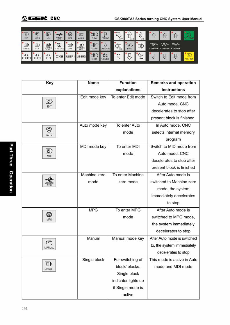
GSK980TA3 Series turning CNC System User Manual
136
Part T
hree O
peratio
n
Key Name Function
explanations
Remarks and operation
instructions
Edit mode key To enter Edit mode Switch to Edit mode from
Auto mode. CNC
decelerates to stop after
present block is finished.
Auto mode key To enter Auto
mode
In Auto mode, CNC
selects internal memory
program
MDI mode key To enter MDI
mode
Switch to MID mode from
Auto mode. CNC
decelerates to stop after
present block is finished
Machine zero
mode
To enter Machine
zero mode
After Auto mode is
switched to Machine zero
mode, the system
immediately decelerates
to stop
MPG To enter MPG
mode
After Auto mode is
switched to MPG mode,
the system immediately
decelerates to stop
Manual Manual mode key After Auto mode is switched
to, the system immediately
decelerates to stop
Single block For switching of
block/ blocks.
Single block
indicator lights up
if Single mode is
active
This mode is active in Auto
mode and MDI mode

Chapter One Operation panel
137
Part T
hree O
peratio
n
Block Skip key For skipping of
block headed
with“/”sign. If the
indicator lights up,
the block is
skipped
This mode is active in Auto
mode and MDI mode
Dry run If dry run is active,
the indicator lights
up
This mode is active in Auto
mode and MDI mode
M.S.T Lock
key
If the M.S.T. lock is
set for ON, the
indicator lights up.
and M,S,T function
output is inactive
This mode is active in Auto
mode and MDI mode
Machine lock
key
If the Machine lock
is set for ON, the
indicator lights up.
and axis output is
inactive
This mode is active in Auto
mode, MDI, Machine zero,
MPG, Manual mode
Spindle control
keys
Spindle CW
Spindle stop
Spindle CCW
In Manual mode, they are
active when the spindle is
in analog control mode
Spindle
override key
For spindle speed
adjustment (It is
active in spindle
analog control)
Any mode
Rapid override Rapid override key This mode is active in Auto
mode, MDI, Machine zero,
MPG, Manual mode
Feedrate
override key
For adjustment of
the federate
This mode is active in Auto
mode, MDI, Machine zero,
MPG, Manual mode
Manual step,
MPG override
selection key
For selection of
manual step, MPG
override.
This mode is active in
MPG and Manual mode
MPG axis
selection key
Corresponding
axis selection for
manual pulse
It is active in MPG mode

GSK980TA3 Series turning CNC System User Manual
138
Part T
hree O
peratio
n
generator (MPG)
Lubricating
on/off key
For lubricating
on/off
This mode is active in Auto
mode, MDI, MPG, Manual
mode
Cooling on/off
key
For cooling on/off This mode is active in Auto
mode, MDI, MPG, Manual
mode
Work light
on/off key
For work light
on/off
This mode is active in
MPG, Manual mode
Manual feed
key
Rapid traverse
For
positive/negative
moving of X, Y, Z
axes in manual
mode.Rapid
traverse on/off
This mode is active in
machine zero, manual
mode, MPG
Any mode
Feed hold key Auto operation of
the system is
stopped by
pressing this key
This mode is active in Auto
mode, MDI mode
Cycle start key The system
operates
automatically by
pressing this key
This mode is active in Auto
mode, MDI mode

Chapter One Operation panel
139
Part T
hree O
peratio
n

GSK980TA3 Series turning CNC System User Manual
140
Part T
hree O
peratio
n
CHAPTER TWO SYSTEM POWER ON/OFF & SAFETY
OPERATION
2.1 System Power-on
Before this GSK980TA3 is powered on, confirm that:
1. The machine is in a normal state.
2. The power voltage conforms to the requirement of the machine.
3. The connection is correct and secure.
The current position (Absolute POS) is displayed after the self-check and initialization are
finished.
POSITION(RELATIVE)
O0002 N0000
U 0.000
W 0.000 FEEDRATE 40 SPDLRIDE 100%
RAPDRIDE 100% WORK NO. 0
OVERRIDE 100% RUN TIME 00:00:00
Message 09:03
Axis Rev 0000
Tool No 0100
Fact Rate 0
Cool Mes OFF
Axis Mes Stop
G00 G98 G97 G40
MDI
Fig.2-1-1
2.2 System Power-off
Before power is off, confirm that:
1. X, Z axes of the CNC are stopped;
2. Miscellaneous functions (spindle, pump etc.) are off;
3. Cut off CNC power prior to machine power cutting off.
Before power is off, check that:
1. LED indicating cycle start of the panel is in a halted state;
2. All movable parts on CNC machine are in a halted state;
3. CNC power is cut off by pressing POWER OFF button.
Emergency Power-off
Under the emergencies during the machine operation, the machine power should be cut off
immediately to avoid the incidents. However, it should be noted that there may be an error

Chapter Two System Power ON/OFF and Safety Operation
141
Part T
hree O
peratio
n
between the system displayed coordinate and the actual position. Therefore, the machine zero
and tool setting operations should be performed again.
Note: Please see the machine builder’s manual for the machine power-off operation.
2.3 Safety Operation
2.3.1 Reset
Press key to the reset CNC if there are abnormal output and axis action about it:
1.All axes movement stops
2.Auto operation ends, modal function and state are held on.
3.By modifying parameter N0:02#6, it is able to set offset vector is unchanged/ deleted during reset.
4.By modifying parameter N0:12#0, it is able to set whether M03, M04, lubricating and cooling is off
or not after reset.
5.By modifying parameter N0:13#1, it is able to set whether the macro common variable is deleted/
unchanged during reset.
6.By modifying parameter N0:13#3,it is able to set whether the expansion output IO port is off or not
during reset.
2.3.2 Emergency Stop
By pressing the emergency stop button in machine operation, the movement of the machine such
as spindle rotation, cooling, etc. are cut off immediately. Release the emergency stop button to leave
the emergency stop state.
Note 1: Make sure that the troubles are removed before the emergency button is eliminated.
Note 2: After the button is released, reference return operation should be done to ensure the correctness of
the coordinate position.
Note 3: Electric shock can be reduced by pressing down the emergency stop button before the system power
ON/OFF. Emergency stop signal is a normally-closed contact signal. When the contact is disconnected,
the system enters emergency stop state, and the machine stops.

GSK980TA3 Series turning CNC System User Manual
142
Part T
hree O
peratio
n
2.3.3 Feed Hold
key can be pressed to make the running pause during the machine operation. It calls for
special notice that the feed hold state can be entered only when the next block is not thread cutting or
cycle command operation after the current command is performed in these operations.
2.3.4 Power-off
Under the emergencies during the machine operation, the machine power should be cut off
immediately to avoid the accidents. However, it should be noted that there may be an error between
the system displayed coordinate and the actual position. Therefore, the tool setting operation should
be performed again.
2.4 Cycle Start and Feed Hold
Cycle start and feed hold keys on panel are used for program start and pause operation in Auto
and MDI mode.
The additional panel can connect to the cycle start and feed hold keys.
By modifying parameter NO:14#0, NO:14#1, it is able to set whether the external start and pause
are shielded.
2.5 Overtravel Protection
Overtravel protection should be employed to prevent the damage to the machine due to overtravel
of the feed axis.
2.5.1 Hardware Overtravel Protection
The stroke limit switches are fixed at the positive and negative maximum stroke position of X and
Z axes respectively. If the overtravel occurs, the running axis decelerates to eventually stop when it
contacts with the stroke switch, and the emergency alarm is issued.
Detailed explanations
Once the workbench presses the limit switch during the operation, the system decelerates
immediately to stop all operation of axes. The control signals of spindle, lubricating and cooling are off
and overtravel alarm occurs.
Steps for eliminating the hardware overtravel alarm

Chapter Two System Power ON/OFF and Safety Operation
143
Part T
hree O
peratio
n
1. Press and hold the overtravel release button, now the system alarm is eliminated.
2. Move the carriage at the opposite side (move out negatively for positive overtravel, vice versa)
to leave the limit switch.
3. Release the overtravel limit button.
2.5.2 Software Overtravel Protection
Software stroke range is set by parameter P46~ P49 on the data parameter (appendix 1). Set
coordinate value of the machine as reference value. If the machine position (machine coordinate)
exceeds software stroke range, overtravel alarm will occur. When the overtravel alarm occurs, move
the axis reversely in the manual mode and then press the reset key to eliminate the alarm.

GSK980TA3 Series turning CNC System User Manual
144
Part T
hree O
peratio
n
CHAPTER THREE INTERFACE DISPLAY & DATA
MODIFICATION & SETTING
3.1 Position Display
3.1.1 Four Ways for Interface Display
Press key to enter Position Interface. There are four modes in this interface such as
【REL.】,【ABS】,【COM.】,【POSC】. They can be viewed by pressing or key.
Detailed information of each interface is as follows:
1) Relative POS.: It displays the current tool position in relative coordinate system (see Fig.
3-1-1-1)
POSITION(RELATIVE) O0001 N0000
O0001 N0000
U 0.000
W 0.000 FEEDRATE 40 SPDLRIDE 100%
RAPDRIDE 100% WORK NO. 0
OVERRIDE 100% RUN TIME 00:00:00
Message 09:03
Axis Rev 0000
Tool No 0100
Fact Rate 0
Cool Mes OFF
Axis Mes Stop
G00 G98 G97 G40
MDI
Fig. 3-1-1-1
Steps for clearing the relative coordinate system: Coordinate system U axis is blinking by
pressing key, and then press key to cancel the coordinate system. The operation of
the W axis is the same as that of the U axis.
Note: The relative POS. will be cleared automatically at power off.
2) Absolute POS.: It displays the current tool position in absolute coordinate system (see Fig.
3-1-1-2)

Chapter Three Interface Display and Data Modification and Setting
145
Part T
hree O
peratio
n
POSITION(ABSOLUTE) O0001 N0000
O0001 N0000
X 0.000
Z 0.000 FEEDRATE 40 SPDLRIDE 100%
RAPDRIDE 100% WORK NO. 0
OVERRIDE 100% RUN TIME 00:00:00
Message 09:03
Axis Rev 0000
Tool No 0100
Fact Rate 0
Cool Mes OFF
Axis Mes Stop
G00 G98 G97 G40
MDI
Fig. 3-1-1-2
3)Integrated interface: The following coordinate position values are displayed:
(A) Position on relative coordinate system
(B) Position on absolute coordinate system
(C) Position on machine coordinate system
(D) Distance-to-go (Display in Auto and MDI mode)
Display page is as follows (Fig.3-1-1-3):
POSITION O0001 N0000
(RELATIVE) (ABSOLUTE)
U 2.563 X 301.059
W 3.587 Z 0.684
(MACHINE) (DISTANCE GO)
X 400.256 X 0.000
Z -100.236 Z 0.000
Message 09:03
Axis Rev 0000
Tool No 0100
Fact Rate 0
Cool Mes OFF
Axis Mes Stop
G00 G98 G97 G40
MDI
Fig. 3-1-1-3
4) Program monitoring mode: In this interface, relative coordinate and absolute coordinate of
the current position and the current block can be displayed at the same time.

GSK980TA3 Series turning CNC System User Manual
146
Part T
hree O
peratio
n
POSITION O0001 N0000
(RELATIVE) (ABSOLUTE)
U 2.563 X 301.059
W 3.587 Z 0.684
O0001;
G50 X250. Z450.;
T0101;
G00 X100. Z200.;
G90 U-10. W-50. R-1.5 F500.;
Message 09:04
Axis Rev 0000
Tool No 0100
Fact Rate 0
Cool Mes OFF
Axis Mes Stop
G00 G98 G97 G40
MDI
Fig. 3-1-1-4
3.1.2 Display of Machining Time, Parts Number, Programming Speed,
Override and Actual Speed
In absolute and relative interfaces of the POS., programming rate, rapid override, federate
override, spindle override, parts number, cutting time can be displayed. Spindle speed, tool number,
cooling state, spindle state, G function code, operation mode, the current date and time etc. can be
displayed in state message column. See the Fig. 3-1-2-1.
POSITION(RELATIVE)
O0002 N0000
U 0.000
W 0.000 FEEDRATE 40 SPDLRIDE 100%
RAPDRIDE 100% WORK NO. 0
OVERRIDE 100% RUN TIME 00:00:00
Message 09:03
Axis Rev 0000
Tool No 0100
Fact Rate 0
Cool Mes OFF
Axis Mes Stop
G00 G98 G97 G40
MDI
Fig. 3-1-2-1
Detailed significances are as follows:
Programming rate: the rate specified by F code.
Rapid override: current rapid override of the system.
Feedrate override: current federate override of the system.
Spindle override: Spindle speed override for adjusting spindle speed.
Parts number: add 1 when M30 (or M99 in the main program) is executed.
Cutting time: It begins timing when auto operation is started. Unit: hour, minute, second.

Chapter Three Interface Display and Data Modification and Setting
147
Part T
hree O
peratio
n
Spindle speed: actual speed from the spindle encoder.
Tool number: tool number and tool offset number of the current tool.
Actual speed: actual processing speed after the magnification is multiplied.
Cooling state: cooling on/off state.
Spindle state: spindle CCW/STOP/CW.
G function code: modal G code of the current system.
3.1.3 Clearing Methods of Parts Number and Cutting Time
1)Switch to the position interface.
2)By pressing key, parts number and cutting time on the interface are blinking. Then
press key, parts number and cutting time are cancelled. If user presses other keys
while they are blinking, the value is not change.
Note 1: The encoder shall be installed on the spindle for displaying the actual spindle speed.
Note 2: Actual rate = F value of the programming rate × magnification. In G00, speed of each axis is set by
data parameter P21~P22. It can be adjusted by the rapid override. The upper cutting speed is set
by data parameter P27. If it exceeds the upper value, the system will alarm.
Note 3: By setting the parameter NO:3#6, it is able to set whether the power-off memory is active for the
parts number and the cutting time.
3.2 Program Display
Press key to enter program display interface. There are three modes in this interface
such as 【PROG.】,【MDI input】,【PRG content】. They can be viewed by pressing or
key. Detailed information of each interface is as follows:
1) Program display: the current program block in memory unit is displayed in this interface (see
Fig. 3-2-1)

GSK980TA3 Series turning CNC System User Manual
148
Part T
hree O
peratio
n
PROGRAM O0001 N0000 O0001;
G50 X250. Z450.;
T0101;
G00 X100. Z200.;
G90 U-10. W-50. R-1.5 F500.;
G90 U-50. W-10. R-3. F350.;
G00 X120. ;
T0202;
M03 S01;
G92 X80. W-65. R5.1 F0.5;
Message 09:04
Axis Rev 0000
Tool No 0100
Fact Rate 0
Cool Mes OFF
Axis Mes Stop
G00 G98 G97 G40
EDIT ADRS Row 2
Fig. 3-2-1
The detailed program edit, please see the chapter 10 operation of editing on operation manual.
Only in program display mode of the edit mode, all contents of the current program can be viewed
and edited by pressing or key.
2) MDI input display: multi-block can be edited and executed in the edit mode. Its program
format is the same as that of the edit mode.
MDI operation applies to simple testing program (see fig. 3-2-2).
PROGRAM O0001 N0000 X
Z G94 F 1000.000 U G97 M W G98 S 0 R T 0100 F M G21 S G40 T P Q SACT 0000
Message 10:04
Axis Rev 0000
Tool No 0100
Fact Rate 0
Cool Mes OFF
Axis Mes Stop
G00 G98 G97 G40
MDI ADRS
Fig. 3-2-2
3) The program (catalogue) displays catalogue display interface. See fig. 3-2-3 for its contents.
(a) System version number: current version of the system used.
(b) Number of the stored programs: number of the stored programs (including subprogram)
Available space: the space can be used.
(c) Used storage capacity: the space occupied by the stored programs (displayed by
character number).
Available space: the space can be used.
(d) Program catalogue: the numbers of the stored programs are displayed in order. The
programs are displayed in the order of the size of the program name.

Chapter Three Interface Display and Data Modification and Setting
149
Part T
hree O
peratio
n
PROGRAM O0001
N0000
SYSTEM EDIT:GSK-980TA3(08) V3.74.083 PRG.NO.USED: 13 FREE:687 MEMORY USED: 704 FREE: 23840 PRG.LIBRARY: O0000 O0001 O0002 O0003 O0004 O0005 O0006 O0007 O0008 O0009 O0010 O0011
00045
Message 10:04
Axis Rev 0000
Tool No 0100
Fact Rate 0
Cool Mes OFF
Axis Mes Stop
G00 G98 G97 G40
MDI
ADRS
Fig. 3-2-3
3.3 Display, Modification and Setting of the Tool Offset
3.3.1 Tool Offset Display
Press key to enter offset Interface. There are numbers 001~064 and101~164 two parts in
this interface. They can be viewed by pressing key continuously. Detailed information is
as follows:
1)Offset interface The offset interface is as follows (see fig. 3-3-1-1):
OFFSET(mm) O0001 N0000
No. X Z R T 000 0.000 0.000 0.000 0 001 0.000 0.000 0.000 0 002 0.000 0.000 0.000 0 003 0.000 0.000 0.000 0 004 0.000 0.000 0.000 0 005 0.000 0.000 0.000 0 006 0.000 0.000 0.000 0 007 0.000 0.000 0.000 0
ABSO X 100.000 Z 100.000 RELA U -169.380 W 122.337
Message 10:09
Axis Rev 0000
Tool No 0100
Fact Rate 0
Cool Mes OFF
Axis Mes Stop
G00 G98 G97 G40
MDI ADRS
Fig. 3-3-1-1
There are numbers 001~064 and101~164 two parts in tool offset interface. Number 001~064 are
used to modify tool offset value, while number 101~164 are used to set tool offset value (see Tool
Setting for detailed functions). Number 000 and 100 are used to move work piece coordinate in
parallel direction. X and Z are tool offset value from the tool post center to the tool nose along the

GSK980TA3 Series turning CNC System User Manual
150
Part T
hree O
peratio
n
direction of X, Z axis respectively. R is the radius compensation value of the imaginary tool nose. T is the
number of the imaginary tool nose (See C Tool Offset Function Instructions for detailed functions).
3.3.2 Tool Offset Modification and Setting
In the offset interface, methods of tool offset setting are as follows:
1) Press to enter the offset interface.
2) Move the cursor to the position where the offset number will be input.
Method 1: Press the page key to enter the page where the offset value to be modified locates.
By pressing the direction keys, the cursor is moved to the position where the offset
to be modified locates.
Method 2: Press key to input the number to be altered. Then press key, the
cursor moves to the input number directly. Finally press key to return to
the state of the data input.
3) Press or key to select the tool offset axis, an input the offset value. After
pressing key, the system will input the offset value automatically, and it will be
displayed on the LCD screen.
Note 1: The offset value can not be set in auto operation.
Note 2: When you adjust the tool offset value in the range 001~064, use U, W to input the adjusting
value. When tool setting is performed in the range 101~164, input actual measurement value
of the X, Z respectively. If the add and subtraction of the current offset value is required,
press key for the X axis, and press key for Y axis, then, input the value to
be added or subtracted, finally press key. For example, the offset value of Z axis is 3,
then input W5 to get Z axis offset value 3+5=8.

Chapter Three Interface Display and Data Modification and Setting
151
Part T
hree O
peratio
n
3.4 Alarm Display
Press key to enter alarm Interface. There are two modes in this interface such as
【alarm signal】,【external information】. They can be viewed by pressing or key.
Detailed information of each interface is as follows:
1. For the alarm interface, see Fig. 3-4-1:
ALARM O0001 N0000 No alarm infomation
Message 10:09
Axis Rev 0000
Tool No 0100
Fact Rate 0
Cool Mes OFF
Axis Mes Stop
G00 G98 G97 G40
MDI
Fig. 3-4-1
The system will enter the alarm interface automatically when troubles occur. The current P/S
alarm number and detailed alarm contents are displayed in the alarm interface, see appendix 2 for
the contents.
2. For the external information interface, see Fig. 3-4-2:
EXTERIOR O0001 N0000
Message 10:09
Axis Rev 0000
Tool No 0100
Fact Rate 0
Cool Mes OFF
Axis Mes Stop
G00 G98 G97 G40
MDI
Fig. 3-4-2

GSK980TA3 Series turning CNC System User Manual
152
Part T
hree O
peratio
n
3.5 Setting Display
Press key to enter the setting interface that includes 【Setting】,【Graph】two types of
display modes. They can be viewed and modified by pressing key repeatedly.
3.5.1 Instruction for 【Setting】Interface Operation
【Setting】interface includes two interfaces 【Setting】 and 【User Password】, which can be
viewed by pressing or key.
1. See the following figure for the setting interface (see 3-5-1-1):
SETTING O0001 N0000
PARM SWT: *OFF ON
PROG KEY: OFF *ON
Datetime set: 00-00-00 00:00:00
Message 10:13
Axis Rev 0000
Tool No 0100
Fact Rate 0
Cool Mes OFF
Axis Mes Stop
G00 G98 G97 G40
MDI
Fig. 3-5-1-1
Operating instructions:
On the above figure, the parameter switch and the program switch ON/OFF and time can be set.
The detailed operation methods and steps are as follows:
(a) Move the cursor to the position of parameter switch, program switch or time setting by
pressing , key.
(b) Press key to set parameter switch or program switch to ON. At this time,
parameter modification, setting and program editing can be performed. The system
displays number P/S100 alarm when the parameter switch is set to ON. Meanwhile, input

Chapter Three Interface Display and Data Modification and Setting
153
Part T
hree O
peratio
n
parameter and then return to the setting interface. Press key to set parameter
switch or program switch to OFF, and the alarm is eliminated automatically after the
parameter switch is off.
(c) In <MDI mode>, move the cursor to time setting, and key in data, time by sequence. Then
press key to confirm it, if input data is wrong, input it again or press key
to cancel it word by word from the back.
2. See the following figure for the user password interface (see fig3-5-1-2)
USERPASSWORD O0001 N0000 Input Pswd: (Lev:System)
Message 10:13
Axis Rev 0000
Tool No 0100
Fact Rate 0
Cool Mes OFF
Axis Mes Stop
G00 G98 G97 G40
MDI
Fig. 3-5-1-2
Operating instructions:
(a)Enter this interface in MDI mode, press key to select the password level. There are
4 levels, which are user, system, manufacturer and LMT.
(b)After selecting the level, input level password and press key to do confirmation. If
the operation is right, it enters to password modification interface and the password can be
modified. The password consists of 1~6 numbers. If the current level is User or LMT, the
system prompts: password is correct. you can modify data parameter and screw-pitch
compensation data. Otherwise, it prompts: the input password is wrong. When the current
level is manufacturer or system, the system prompts: password is correct. You can modify
data parameter and screw-pitch compensation data. Otherwise, it prompts: the input
password is wrong.
Note: The password is not always numbers, it includes “-” and “.”.
(c)After modification, input the data again if wrong password is input or original input password

GSK980TA3 Series turning CNC System User Manual
154
Part T
hree O
peratio
n
is inactive.
3.5.2 Operating Instructions for 【Graph】Interface
【Graph】interface includes two interfaces 【Graph】 and 【Drafting】, which can be viewed by
pressing or key.
1. See the following figure for the 【Graph】 interface (see 3-5-2-1):
Graphic parameter O0001 N0000 Coordinat = 1 (XZ:0 ZX:1)
Scalerate = 2.000 Center X = 0.000 (X Absolute) Center Z = 0.000 (Z Absolute) X Maximum = 100.000 Z Maximum = 100.000 X Minimum = -100.000
Z Minimum = -100.000
Message 10:04
Axis Rev 0000
Tool No 0100
Fact Rate 0
Cool Mes OFF
Axis Mes Stop
G00 G98 G97 G40
MDI No. 001
Fig. 3-5-2-1
Operation instructions:
1). Graph (parameter) interface, see Fig. 3-5-2-1.
A. Significances of Graph (parameter)
Coordinate selection: There are 2 options for setting drafting plane, see the figure:
Set 0 for XZ coordinate, and set 1 for ZX coordinate, see figure 3-5-2-2.
X
Z
( 0 ) ( 1 )
X
Z
Fig. 3-5-2-2
Scaling ratio: To set drafting scale.
Graph center: To set the workpiece coordinate value to the LCD center in workpiece
coordinate system.
Maximum and minimum value: After maximum and minimum values for the displayed axis are
set, CNC system scales automatically and center value of the graph is set automatically.
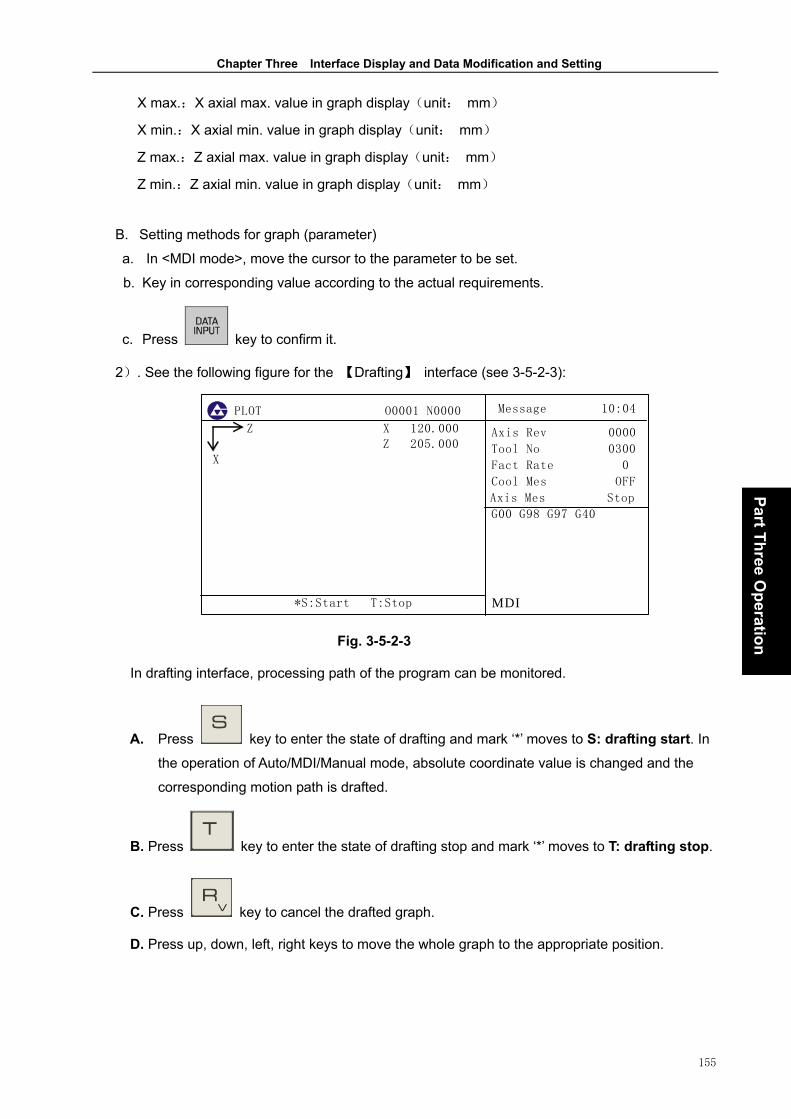
Chapter Three Interface Display and Data Modification and Setting
155
Part T
hree O
peratio
n
X max.:X axial max. value in graph display(unit: mm)
X min.:X axial min. value in graph display(unit: mm)
Z max.:Z axial max. value in graph display(unit: mm)
Z min.:Z axial min. value in graph display(unit: mm)
B. Setting methods for graph (parameter)
a. In <MDI mode>, move the cursor to the parameter to be set.
b. Key in corresponding value according to the actual requirements.
c. Press key to confirm it.
2). See the following figure for the 【Drafting】 interface (see 3-5-2-3):
PLOT O0001 N0000 Z X 120.000 Z 205.000 X
*S:Start T:Stop
Message 10:04
Axis Rev 0000
Tool No 0300
Fact Rate 0
Cool Mes OFF
Axis Mes Stop
G00 G98 G97 G40
MDI
Fig. 3-5-2-3
In drafting interface, processing path of the program can be monitored.
A. Press key to enter the state of drafting and mark ‘*’ moves to S: drafting start. In
the operation of Auto/MDI/Manual mode, absolute coordinate value is changed and the
corresponding motion path is drafted.
B. Press key to enter the state of drafting stop and mark ‘*’ moves to T: drafting stop.
C. Press key to cancel the drafted graph.
D. Press up, down, left, right keys to move the whole graph to the appropriate position.

GSK980TA3 Series turning CNC System User Manual
156
Part T
hree O
peratio
n
3.6 Display, Modification and Setting of the Parameter
3.6.1 Parameter Display
Press key to enter parameter Interface. There are two kinds of display modes, which are
【Parameter】,【Screw-pitch compensation parameter】. They can be viewed by pressing key
continuously.
1). See the figure for parameter interface (see 3-6-1-1):
PARAMETER O0001 N0000 No. DATA No. DATA
001 00000000 009 00001100 002 01000001 010 00000000 003 01000100 011 00000001 004 00100000 012 00000000 005 01000000 013 00000000 006 00000000 014 10001111 007 00000000 015 00000000 008 00000000 016 00000000
LAN SCW *** MDSP WHLA RAD *** *** Bit0:Unused
Message 10:04
Axis Rev 0000
Tool No 0100
Fact Rate 0
Cool Mes OFF
Axis Mes Stop
G00 G98 G97 G40
MDI No. 001
Fig. 3-6-1-1
Detailed explanations for the parameter where the cursor locates are displayed in the lower part
of the screen. See appendix 1 Parameter Explanation for definitions of each parameter.
2). See the following figure for the screw pitch compensation interface (See 3-6-1-2):
WORMCOMPENSATE(mm/1000) O0001 N0000
No. X(um) Z(um) 000 0 0 001 0 0 002 0 0 003 0 0 004 0 0 005 0 0 006 0 0 007 0 0
008 0 0 009 0 0
ADRS
Message 10:04
Axis Rev 0000
Tool No 0100
Fact Rate 0
Cool Mes OFF
Axis Mes Stop
G00 G98 G97 G40
MDI
Fig. 3-6-1-2

Chapter Three Interface Display and Data Modification and Setting
157
Part T
hree O
peratio
n
Function settings for the screw pitch compensation number, please refer to Machine
Debugging-Screw Pitch Compensation.
3.6.2 Modification and Setting for Parameter and Screw Pitch
Compensation Value
There are four methods for modifying and setting parameter and screw pitch compensation
value.
1. Modify it in the page:
1) Select <MDI> operation mode.
2) Enter <Setting> page, and turn on the parameter switch in 【Setting】interface. 【Password】
is required to be input for some parameter modification, See 3.5.1 for detailed operation.
3) Press key to enter the parameter display page.
4) Move the cursor to the position where the parameter to be modified locates.
(1). Press the page key to display the page where the parameter to be altered. Press the
direction key (use left and right keys in bit parameter) to select the parameter to be
altered.
(2). Press key and input the sequence number of the parameter to be modified.
Then press key to confirm it, and the cursor will move to the number directly.
5) Input new parameter value by numerical keys.
6) Press key, the parameter value is input and displayed.
7) Turn off the parameter switch after parameter setting and confirmation is finished.
2. Loading and saving with backup disk
1) Loading parameter value from backup (see Fig.3-6-2-1)
The system has parameter and screw pitch compensation backup function. Take parameter
value as an example bellow. The backup function of screw pitch compensation value is similar to that
of the parameter value. Therefore, there is no further explanations. In parameter value I/O interface,
select parameter input and output function by moving operation keys up and down. When parameter
output function is selected, the parameter being used (including bit parameter and data parameter)
can be backed up by the system. Back up files according to selected A, B, C OR D (selected by left
and right operation keys). A and B are read-only disks, while C and D are read-write disks.
Parameters in disk A and B are set in factory (A is default value for servo drive and B is default value

GSK980TA3 Series turning CNC System User Manual
158
Part T
hree O
peratio
n
for step drive). Disk A, B, C or D can be processed during loading, while only disk C, D can be
processed during saving. When selecting parameter loading function, select A, B, C or D by left and
right operation keys, namely, electronic disk number of the parameter file is selected. Then press
input key to finish the loading, the parameter that CNC is using becomes the newly input parameter.
Detailed operation process is as follows:
① Set the parameter switch as ON.
② Select <MDI> mode.
③ Press key to enter parameter display interface
④ Press key to enter parameter value I/O page.
⑤ Move the cursor up and down to “Parameter loading” position. Select the disk to be loaded
by left and right key.
⑥ By pressing key, the system will open corresponding electronic disk from the
storage and load the data. After that, “Loading completion” is displayed in the lower left
part of LCD.
2) Store the parameter to the disk (See the Fig. 3-6-2-1)
①~ are the same as that above.④
Move the cursor up and down to “Parameter storing” position. Select the disk to be loaded ⑤
by left and right key.
⑥ By pressing key, the system will write the parameter value into the user selected
electronic disk. After that, “input completion” is displayed in the lower left part of LCD.
If “The electronic disk”, ”Parameter” and ”Backup” already exist in user partition, new
parameter will cover the original parameter.

Chapter Three Interface Display and Data Modification and Setting
159
Part T
hree O
peratio
n
ParameterValue O0001 N0000 ReadParame: *A B C D
SaveParame: *C D
<IN>read,<OUT>save
A,B:default(A:servo,B:DY3)
C,D:user
Message 10:13
Axis Rev 0000
Tool No 0100
Fact Rate 0
Cool Mes OFF
Axis Mes Stop
G00 G98 G97 G40
MDI
Fig. 3-6-2-1
The disk loading and storage of the screw pitch error compensation parameter are similar to that
of the system parameter. In screw pitch parameter interface, press key to enter screw
compensation electronic disk operation panel.
3. From CNC to CNC
The parameter and screw pitch error compensation can communicate with each by two
different systems. For detailed operation, see sectioon10.5 Communication between CNC and
CNC.
4. Transmission with software
Connect PC and CNC with communication cable, turn on the CNC program switch, and open
user communication software in PC. See the chapter ten Serial port communication for
detailed operations.
3.7 Diagonosis Display
DI/DO signal state between CNC and the machine, system interface signal, keys state of MDI
panel, CNC input/output state, system internal CNC state signal, etc. are displayed on the diagnosis
interface. Please refer to appendix three for corresponding significances of each diagnosis number.
This diagnosis is used for detecting the operation state between CNC interface signal and internal
signal, which can not be modified.

GSK980TA3 Series turning CNC System User Manual
160
Part T
hree O
peratio
n
3.7.1 Diagnosis Data Display
Press key to enter diagnosis interface, which consists of 【Diagnosis】,【Machine Panel】,
【Macro Variable】three display modes. They can be viewed and modified by pressing key
repeatedly.
1. 【Diagnosis】interface can be viewed by pressing or key. See figure 3-7-1-1.
DIAGNOSTIC O0001 N0000 No. DATA No. DATA
001 00000000 009 00001100 002 01000001 010 00000000 003 01000100 011 00000001 004 00100000 012 00000000 005 01000000 013 00000000 006 00000000 014 10001111 007 00000000 015 00000000 008 00000000 016 00000000
Machine tool side input signal(IOboard) Bit0:TCP DIQP DECX DITW *SP ST DECZ *ESP
No. 001
Message 10:09
Axis Rev 0000
Tool No 0100
Fact Rate 0
Cool Mes OFF
Axis Mes Stop
G00 G98 G97 G40
MDI
Fig. 3-7-1-1
In diagnosis display interface, there are three diagnosis contents display columns in the lower
part of the LCD. They display the contents of the diagnosis number where the cursor locates. See the
appendix III for corresponding detailed significances of each diagnosis number.
2. See figure 3-7-1-2 for the contents of 【Machine Panel】 interface.
OPERATOR O0001 N0000
MLK(KEY1): *OFF ON
AFL(KEY2): *OFF ON
SBK(KEY3): *OFF ON
DRN(KEY4): *OFF ON
BDT(KEY5): *OFF ON
POSITION(RELATIVE)
U 0.000
W 0.000
Message 10:13
Axis Rev 0000
Tool No 0100
Fact Rate 0
Cool Mes OFF
Axis Mes Stop
G00 G98 G97 G40
MDI
Fig. 3-7-1-2

Chapter Three Interface Display and Data Modification and Setting
161
Part T
hree O
peratio
n
When the machine panel displays pages, use ”1. 2. 3. 4. 5” keys to switch Machine lock, M.S.T
Lock, Single Block, Dry run, Block skip. Their functions are the same as that of the , ,
, , keys on the panel.
3. See figure 3-7-1-3 for the contents of 【Macro variable】 interface.
MACRO O0001 N0000 No. DATA No. DATA
200 0.000 208 0.000 201 0.000 209 0.000 202 0.000 210 0.000 203 0.000 211 0.000 204 0.000 212 0.000 205 0.000 213 0.000 206 0.000 214 0.000 207 0.000 215 0.000 POSITION(RELATIVE)
U -169.380 W 122.337
Message 10:09
Axis Rev 0000
Tool No 0100
Fact Rate 0
Cool Mes OFF
Axis Mes Stop
G00 G98 G97 G40
MDI No. 200
Fig. 3-7-1-3
There are two parts in macro variable interface, which are #200~#231 power-off clearing and
#500~#515 power-off memory. See variable instructions in User Macro Variable for detailed
functions.
In macro variable interface, macro variable setting and modification are the same as that of the
tool compensation. See variable instructions in User Macro Variable for detailed functions.

GSK980TA3 Series turning CNC System User Manual
162
Part T
hree O
peratio
n
CHAPTER FOUR MANUAL OPERATION
Press the to enter manual operation mode, which mainly includes the manual feed, the
spindle control and the machine panel control etc.
4.1 Coordinate Axis Movement
In the mode of the manual operation, X and Z axes can be operated at the manual feedrate or
the manual rapid traverse rate.
4.1.1 Manual Feed
Press the feed axis or key, and arrow indicates the direction here. The axis
movement is stopped after releasing the key. In this case, the feed override can be adjusted to
change the feedrate and the operation is similar to X-axis.
4.1.2 Manual Rapid Traverse
Press key and enter the manual rapid traverse state after the indicator on the
upper part of the edit panel is lighted up, and then press the key of feed axis, each axis moves at the
rapid traverse rate.
Note 1: The feedrate performed in manual rapid traverse, the time constant and the acceleration/
deceleration modes are same as rapid traverse rate specified by program commands (G00
positioning).
Note 2:When rapid traverse is active (Rapid traverse indicator lights up), NO.005 Bit6
determines whether the rapid move speed is manual feedrate or rapid traverse speed before the
reference position returns after power on.
Note3: In Edit/MPG mode, the key is inactive and the indicator is off. Rapid feed can be selected in other
modes and it is cancelled after the other mode is shifted.

Chapter Four Manual Opoeration
163
Part T
hree O
peratio
n
4.1.3 Manual Feed and Manual Rapid Traverse Rate Selection
When the manual feed operation is performed, federate override adjustment keys
on the panel can be used to select the manual federate override (16 in total,
0%~150%).
See the table 4-1-3-1:
Table 4-1-3-1
Feedrate override (%) Feedrate (mm/min)
0 0
10 1.5
20 3.2
30 5.0
40 7.9
50 12.6
60 15
70 32
80 50
90 79
100 126
110 200
120 320
130 500
140 790
150 1260
Note: The table has an error margin of 3%.
When the manual rapid traverse is performed, the manual rapid traverse rate can be selected by
pressing rapid traverse adjustment keys . Five gears rapid override are
available: Fo, 25%, 50%, 75% and 100% (Fo is set by the data parameter P32).
Note 1: The rapid override selection is active for the following traverse speed
(1) G00 rapid feed
(2) Rapid feed in canned cycle
(3) Rapid feed in the command G28

GSK980TA3 Series turning CNC System User Manual
164
Part T
hree O
peratio
n
(4) Manual rapid feed
(5) Rapid feed in the manual reference return
Example: when the rapid feedrate is 8 m/min, and if the override is 50%, the speed is 4 m/min.
Note 2: The rapid override is inactive when the axis is moving.
4.2 Spindle Control
4.2.1 Spindle CW (Negative rotation)
: S rotation speed can be specified in MDI mode, the spindle rotates CW by pressing this
key in the mode of manual/MPG/single step.
4.2.2 Spindle CCW (Positive rotation)
: S rotation speed can be specified in MDI mode, the spindle rotates CCW by pressing this
key in the mode of manual/MPG/single step.
4.2.3 Spindle Stop
: The spindle stops in the mode of manual/MPG/single step by pressing this key.
4.3 Other Manual Operations
4.3.1 Cooling Control
: It is a compound key. The cooling is shifted between on and off. Its ON/OFF state can
be viewed on LCD screen.
4.3.2 Lubricating Control
: It is a compound key. The lubricating function is shifted between on and off.

Chapter Four Manual Opoeration
165
Part T
hree O
peratio
n
4.3.3 Manual Tool Change
:In Manual/MPG/Single step mode, by pressing this key, tool post rotates to change for
another tool. Total tool number can be set by the data parameter P81. See the machine tool
manufacturer’s manual.
4.4 Tool Setting
Several tools are needed for processing a part. Because the tool installation error and tool error
exist, tool nose positions do not entirely coincide when the tools rotate to the cutting position. In order
to facilitate user programming without caring about the deviation between tools, the system is
designed with tool offset automatic generating method. After tool setting, user makes programs
according to part drawing and machining techniques without having to concern the deviation between
tools. User only have to call corresponding tool compensation value in programs. The system is
designed with many modes such as fixed-point tool setting, tool setting by test cutting and tool setting
by machine zero return.
4.4.1 Fixed-point Tool Setting
When setting offset in interface, if press key after inputting the address key U (or W),
the current relative coordinate value is set as offset value corresponding to this address.
Fig. A Fig. B
Fig. 4-4-1-1
Establish a workpiece coordinate system before the fixed-point tool setting.
Steps:
1)Select a tool without tool offset at random (usually the 1st tool, this tool will be used as the
reference tool)

GSK980TA3 Series turning CNC System User Manual
166
Part T
hree O
peratio
n
2)Position the tool nose of the reference tool to a point (tool setting point), as shown in Fig. A
3)Clear the relative coordinate (U, W). See section 3.1.1 for detailed operations
4)Press key and move the cursor by , keys to select a offset and take
it as the offset of the reference tool.
First confirm whether the X and Z axial tool offset values are zero or not. If it is not zero,
clear it as the following method.
Select number 001~064 tool offset by moving the cursor, input X0, Z0 to clear it.
5)After the tool is moved to a safe position, select another tool and move it to the setting point.
As shown in Fig. B.
6)Press key and select a offset in 001~064 as the offset of the tool. Then confirm
whether the X and Z axial tool offset values are zero or not. If it is not zero, clear it as above
step 4)introduced.
7)Press address key , then press key to input the tool offset value of X axis into
the corresponding offset number of that.
8)Press address key , hen press key to input the tool offset value of Z axis into
the corresponding offset number of that.
9)Repeat the steps from 5 to 8 to set the tool offset for other tools.
4.4.2 Tool Setting by Test Cutting
When the workpiece coordinate system is not changed, perform tool setting by test cutting.
Operation steps are as follows (Establish coordinate system on the part end surface):
Z α
Surface A
Surface B
X
Fig. 4-4-2-1

Chapter Four Manual Opoeration
167
Part T
hree O
peratio
n
1. Select a tool without tool offset at random (supposing it is the 1st tool)
2. In manual mode, it cuts along surface A in negative direction of X axis.
3. Retract the tool along the positive direction of the X axis when Z axis is not moving and stop
the spindle.
4. Press key to enter the Offset interface, and move the cursor by ,
keys to select offset 101 and take it as the offset of the tool.
5. Key in by sequence of the address key “Z”, numerical key “0” and key.
6. In manual mode, it cuts along surface B in negative direction of Z axis.
7. Retract the tool along the positive direction of the Z axis when X axis is not moving and stop
the spindle.
8. Measure diameter “a” (Supposing α’=30)
9. Press key to enter the Offset interface, and move the cursor by ,
keys to select offset 101.
10. Key in by sequence of the address key “X”, numerical key“3”, “0” and key.
11. Move the tool to the safe position for tool changing.
12. Change another tool (supposing it is the 2nd tool) without tool offset.
Z α ’
Surface A1
Surface B1
X
β’
Fig. 4-4-2-2
13. In manual mode, it cuts along surface A1 in negative direction of X axis.
14. Retract the tool along the positive direction of the X axis when Z axis is not moving and stop
the spindle.
15. Measure the distance “β” from surface A1 to the workpiece coordinate system (Supposing
β=1).
16. Press key to enter the Offset interface, and move the cursor by ,
keys to select offset of 102.

GSK980TA3 Series turning CNC System User Manual
168
Part T
hree O
peratio
n
17. Key in by sequence of the address key “Z”, symbol key“-”, numerical key“1” and key.
18. In manual mode, it cuts along surface B1 in negative direction of Z axis.
19. Retract the tool along the positive direction of the Z axis when X axis is not moving and stop
the spindle.
20. Measure the diameter "α’" (Supposing α’=28)
21. Press key to enter the Offset interface, and move the cursor by ,
keys to select offset of 102.
22. Key in by sequence of the address key “X”, numerical key“2”, “8” and key.
23. Repeat the steps from 11 to 22 to perform tool setting operation for other tools.
4.4.3 Tool Setting by Machine Zero Return
There is no reference tool in this tool setting method. When the tool is worn or to be adjusted, it
only needs to be set again. Machine zero return should be done before the tool setting (See section
8.2 in this manual for machine zero return). The machining can be continued by performing machine
zero return once after reset, which is convenient for the operation.
。M achine zero point
Z
X
β
α
Surface A
Surface B
X 0
Z0
Operation steps are as follows:
1) Press key to enter Machine Zero Return mode. Press positive direction keys of the X
and Z axes to make the two axes return to machine zero point.
Fig.4-4-3-1

Chapter Four Manual Opoeration
169
Part T
hree O
peratio
n
Z α
Surface A
Surface B
X
Fig. 4-4-3-2
2) Select a tool without tool offset at random (supposing it is the 1st tool)
3) In manual mode, it cuts along surface A in negative direction of X axis.
4) Retract the tool along the positive direction of the X axis when Z axis is not moving and stop the
spindle.
5) Press key to enter the Offset interface, and move the cursor by , keys to
select offset 101 as the offset number of the tool.
6) Key in by sequence of the address key “Z”, numerical key“0” and key.
7) In manual mode, it cuts along surface B in negative direction of Z axis.
8) Retract the tool along the positive direction of the X axis when Z axis is not moving and stop the
spindle.
9) Measure the diameter "α’" (Supposing α’=30)
10) Press key to enter the Offset interface, and move the cursor by ,
keys to select offset of 101.
11) Key in by sequence of the address key “X”, numerical key“3”, “0” and key.
12) Move the tool to the safe position for tool changing.
13) Change another tool (supposing it is the 2nd tool) without tool offset.

GSK980TA3 Series turning CNC System User Manual
170
Part T
hree O
peratio
n
Z α ’
Surface A1
Surface B1
X
β’
Fig. 4-4-3-3
14) In manual mode, it cuts along surface A1 in negative direction of X axis.
15) Retract the tool along the positive direction of the X axis when Z axis is not moving and stop
the spindle.
16) Measure the distance “β” from surface A1 to the workpiece coordinate system (Supposing
β=1).
17) Press key to enter the Offset interface, and move the cursor by ,
keys to select offset of number 102.
18) Key in by sequence of the address key “Z”, symbol key “-”, numerical key “1” and
key.
19) In manual mode, it cuts along surface B1 in negative direction of Z axis.
20) Retract the tool along the positive direction of the Z axis when X axis is not moving and stop
the spindle.
21) Measure diameter “a” (Supposing α’=28)
22) Press key to enter the Offset interface, and move the cursor by ,
keys to select offset of number 102.
23) Key in by sequence of the address key “X”, numerical key“2”, “8”and key.
24) Repeat the steps from 12 to 23 to perform tool setting operation for other tools.

Chapter Four Manual Opoeration
171
Part T
hree O
peratio
n
4.5 Offset Alteration
Offset can be input by U, W.
Example: If 0.010mm is need to be added to the offset value of the Z axis, press key to
enter the Offset interface, and move the cursor by , keys to select a offset number of
001, then input U0.010 and press key, and 0.010mm is added to the original offset value
automatically by the system.

GSK980TA3 Series turning CNC System User Manual
172
Part T
hree O
peratio
n
CHAPTER FIVE MPG/SINGLE-STEP OPERATION
Press key to enter MPG/ Single step mode, which can be selected by bit parameter
NO:1#3. In the MPG/single step feed mode, the machine moves according to the defined step length
in the system each time.
5.1 Step Feed
Set parameter NO:1#3 to 0, and press to enter Step operation mode. The move
increment can be selected by pressing any key of , , , and it is displayed on the
interface. The step increment 0.100 is displayed on <Position> interface by pressing key,
(See figure 5-1-1):
POSITION(RELATIVE)
O0001 N0000
U 0.000
W 0.000 STEP INC 0.100 SPDLRIDE 100%
RAPDRIDE 100% WORK NO. 0
OVERRIDE 100% RUN TIME 00:00:00
Message 09:03
Axis Rev 0000
Tool No 0100
Fact Rate 0
Cool Mes OFF
Axis Mes Stop
G00 G98 G97 G40
STEP
Fig. 5-1-1
Press X- or X+ key, it can move the X axis negatively or positively by a step increment. Press Z-
or Z+ key, it can move the Z axis negatively or positively by a step increment.
Note 1: The speed of single step movement and that of the manual feed are the same.
Note 2: Rapid override and federate can be altered in Single Step mode.

Chapter Five MPG/Sing Step Operation
173
Part T
hree O
peratio
n
5.2 MPG (Manual pulse generator) Feed
Set parameter NO:1#3 to 1, and press to enter MPG operation mode. The move
increment can be selected by pressing any key of , , , and it is displayed on the
interface. The MPG increment 0.100 is displayed on <Position> interface by pressing key,
(See figure 5-2-1):
POSITION(RELATIVE)
O0001 N0000
U 0.000
W 0.000 HNDL INC 0.100 SPDLRIDE 100%
RAPDRIDE 100% WORK NO. 0
OVERRIDE 100% RUN TIME 00:00:00
Message 09:03
Axis Rev 0000
Tool No 0100
Fact Rate 0
Cool Mes OFF
Axis Mes Stop
G00 G98 G97 G40
HANDLE (X)
Fig. 5-2-1
THE MPG EXPERIENCE IS AS THE FIGURE BELLOW:
Manual pulse generator(MPG)
5.2.1 Moving Axis and Direction Selection
In MPG mode, press , or key, the corresponding axis is selected and it will
be controlled by MPG. For example, X axis can be moved by moving MPG after key is
pressed (See figure 5-2-1-1).

GSK980TA3 Series turning CNC System User Manual
174
Part T
hree O
peratio
n
Generally, MPG CW is for positive feed, and CCW for negative feed.
POSITION(RELATIVE)
O0001 N0000
U 0.000
W 0.000 HNDL INC 0.100 SPDLRIDE 100%
RAPDRIDE 100% WORK NO. 0
OVERRIDE 100% RUN TIME 00:00:00
Message 09:03
Axis Rev 0000
Tool No 0100
Fact Rate 0
Cool Mes OFF
Axis Mes Stop
G00 G98 G97 G40
HANDLE (X)
Fig. 5-2-1-1
The MPG (Manual pulse generator) feed direction is defined by its rotation direction. See the
manufacturer’s instructions for details. Generally, MPG CW is for positive feed and CCW is for
negative feed.
5.2.2 Instructions for MPG Feed
1. Relationship between MPG scale and machine movement amount is shown in the table
bellow:
Table 5-2-2-1
Movement amount of each MPG scale
MPG increment
(mm) 0.001 0.01 0.1
Machine
movement
amount (mm)
0.001 0.01 0.1
2. Values in the above table vary with mechanical transmission. See manufacturer’s instructions
for details.
3. The rotation speed of the MPG should be less than 5 r/s. If it is over 5 r/s, the scale may not coincide
with the movement amount.
Blinking

Chapter Five MPG/Sing Step Operation
175
Part T
hree O
peratio
n
4. The and keys are only active in MPG/Step mode.
5.3 The Miscellaneous Control in MPG/Step Operation
It is the same as the manual operation mode. Refer to the section 4.2 and 4.3 of this operation
manual for details.

GSK980TA3 Series turning CNC System User Manual
176
Part T
hree O
peratio
n
CHAPTER SIX MDI OPERATION
The MDI operation function is added besides data input, parameter and offset alteration
functions. Commands that are input directly can be executed with this function. There are detailed
instructions for MDI, parameter and offset alteration in interface display and data alteration and
setting, chapter 3. MDI operation function is introduced in this chapter.
6.1 MDI Blocks Input
Program input in 【MDI】mode is the same as that of the Edit mode, see edit operations, chapter 7.
Input steps in 【MDI】mode are introduced bellow.
Example: Steps for inputting a block G00 X50 Z50 by 【MDI】operation interface are as follows:
1. Press key to enter MDI mode
2. Press key to enter 【MDI】operation interface, see section 3.2 for detailed operations.
(See figure 6-1-1)
3. After the address key G00 is input, press key to confirm the operation and G00 is
displayed on LCD screen. Input X50 and press key to confirm. Then input Z50 and
press key to confirm. At this time, programs are input and can be viewed in the
interface, see the figure bellow:
PROGRAM O0001 N0000 X 50.000 G00 Z 50.000 G94 F 250.000
U G97 M W G98 S 0 R T 0100 F M G21 S G40 T P Q SACT 0000
Message 10:04
Axis Rev 0000
Tool No 0100
Fact Rate 0
Cool Mes OFF
Axis Mes Stop
G00 G98 G97 G40
MDI ADRS
Fig. 6-1-1

Chapter Six MDI Operation
177
Part T
hree O
peratio
n
6.2 MDI Block Operation and Stop
The MDI can be performed by pressing key after the command is input as the steps in
section 6.1. The block operation can be stopped by pressing or pressing key during
operation.
Note: MDI operation must be performed in the MDI mode!
6.3 MDI Block Words Alteration and Clearing
If there are errors during words input, press key to cancel it word by word. If the errors
are found after it is finished, input right one to take the place of the wrong one or press key to
clear all contents, and then input it again.
6.4 Conversion of Operation Modes
The MDI mode operation may stop immediately after shifting to the other modes. Specific as
follows:
1)After shifting to Edit, AUTO mode, the machine is stopped after the current block is performed.
2)After shifting to Manual, MPG, Step mode, the machine is stopped immediately.
3)After shifting to Machine zero return interface, the machine decelerates to stop.

GSK980TA3 Series turning CNC System User Manual
178
Part T
hree O
peratio
n
CHAPTER SEVEN EDIT OPERATION
7.1 Program Edit
To prevent the program from being modified or deleted by people at random, the system is
designed with a program switch. The switch must be turned on before program editing. Please refer
to switch setting in section 3.5.1.
Workpiece program editing should be performed in edit mode. Press key to enter
edit mode.
Press key to enter program display interface, and the program can be edited and
altered (See Fig. 7-1-1).
PROGRAM O0001 N0000 O0001;
G50 X250. Z450.;
T0101;
G00 X100. Z200.;
G90 U-10. W-50. R-1.5 F500.;
G90 U-50. W-10. R-3. F350.;
G00 X120. ;
T0202;
M03 S01;
G92 X80. W-65. R5.1 F0.5;
Message 09:04
Axis Rev 0000
Tool No 0100
Fact Rate 0
Cool Mes OFF
Axis Mes Stop
G00 G98 G97 G40
EDIT ADRS Row 2
Fig. 7-1-1
7.1.1 Program Creation
7.1.1.1 Creation of the Program Number
By setting the parameter NO:2#7, it is able to set whether the block number is active or not. If the
parameter is set to 1, the block number is inserted automatically during program editing, increment of
the block number is set by the data parameter P50.

Chapter Seven Edit Operation
179
Part T
hree O
peratio
n
7.1.1.2 Input and Storage of the Program
1. Press key to enter the Edit mode.
2. Press key to enter the Program interface (See figure 7-1-1-2-1)
PROGRAM O0001 N0000 O0001;
G50 X250. Z450.;
T0101;
G00 X100. Z200.;
G90 U-10. W-50. R-1.5 F500.;
G90 U-50. W-10. R-3. F350.;
G00 X120. ;
T0202;
M03 S01;
G92 X80. W-65. R5.1 F0.5;
Message 09:04
Axis Rev 0000
Tool No 0100
Fact Rate 0
Cool Mes OFF
Axis Mes Stop
G00 G98 G97 G40
EDIT ADRS Row 2
Fig. 7-1-1-2-1
3. Press address key , and key in numerical keys by sequence of , , ,
(Program O3333 creation for an example). O3333 is displayed behind the numerical column.
See the figure bellow (Fig. 7-1-1-2-2).
PROGRAM O0001 N0000 O0001;
G50 X250. Z450.;
T0101;
G00 X100. Z200.;
G90 U-10. W-50. R-1.5 F500.;
G90 U-50. W-10. R-3. F350.;
G00 X120. ;
T0202;
M03 S01;
G92 X80. W-65. R5.1 F0.5;
Message 09:04
Axis Rev 0000
Tool No 0100
Fact Rate 0
Cool Mes OFF
Axis Mes Stop
G00 G98 G97 G40
EDIT ADRS O 3333 Row 2
Fig. 7-1-1-2-2
4. Press key to create a new program, as shown in the following figure (Fig. 7-1-1-2-3).

GSK980TA3 Series turning CNC System User Manual
180
Part T
hree O
peratio
n
PROGRAM O3333 N0010 O3333;
N10
%
Message 09:04
Axis Rev 0000
Tool No 0100
Fact Rate 0
Cool Mes OFF
Axis Mes Stop
G00 G98 G97 G40
EDIT ADRS Row 2
Fig. 7-1-1-2-3
5. Input the edited program word by word, and press key after a block is finished. Switch
to other interface (e.g. interface) after a program is finished, or switch to other working mode
and at the same time, the program is saved automatically.
Note 1: In Edit mode, only a complete word can be input. Single character or number can
not be input.
Note 2: If there are errors during block inputting, press key to cancel the whole
block.
7.1.1.3 Search of the Sequence Number, Character and Line Number
Sequence number retrieval, which means searching a sequence number of a program, is used to
start program execution or edit from the retrieved sequence number. The block skipped for searching
has no effect on the state of the CNC. (The coordinate value, M, S, T code and G code of the skipped
block have no effect on the coordinate value and mode value of the CNC).
If execution starts from a block of the retrieved program, the machine state and CNC state should
be checked. In addition, they should be consistent with corresponding M, S, T code and the
coordinate system setting (it can be set by MDI mode) before execution.
Character search is used to search the specified address or numerical characters in program,
which is mainly used in edit program.
Steps of searching sequence number, characters in program:
1) Press key to enter Edit mode.

Chapter Seven Edit Operation
181
Part T
hree O
peratio
n
2) Open the target program in interface. See 6.1 for detailed operations.
There are two methods for searching characters:
1)Scanning: find the page where the target locates by the page key, and then move the
cursor to the target position.
2)Search method: input the character or sequence number to be searched, and press
or key to search it upward or downward. The same one downward can be searched,
the alarm occurs if it is not searched.
7.1.1.4 Cursor Positioning
In edit mode, select key to enter program page.
1) Press key to move up the cursor to the last line. When the line which the cursor
is in is bigger than the end row of the last line, the cursor can be moved up to the end of
the last line.
2) Press key to move down the cursor to the next line. When the line which the
cursor is in is bigger than the end row of the last line, the cursor can be moved down to
the end of the next line longer
3) Press to move right the cursor to one row. When the cursor is in the end of the
line, it can be moved to the home of the next line.
4) Press to move left the cursor to one row. When the cursor is in the home of the
line, it can be moved to the end of the last line
5) Press to page up the screen and the cursor moves to the same position of the
last screen.
6) Press to page down the screen and the cursor moves to the first row of the first
line in the next screen.

GSK980TA3 Series turning CNC System User Manual
182
Part T
hree O
peratio
n
7) Press key, the cursor moves to the head of the program.
7.1.1.5 Character Insertion, Deletion and Alteration
By the methods in 7.1.1.3 and 7.1 .1.4, move the cursor to the position to be altered.
1. Insertion of the character
After inputting the data, press key, the input contents will be inserted at the right side of
the cursor.
2. Deletion of a character
Move the cursor to the character to be deleted, and the character where cursor locates will be
deleted by pressing key. If the key is pressed continuously, the contents at the
right side of the cursor will be deleted one by one.
3. Alteration of the character
Move the cursor to the character to be altered, then input the contents and press key,
the contents is input to take the place of the character where the cursor locates.
7.1.2 Deletion of a program
Steps for deleting a program in the memory are as follows:
1) Select <Edit> mode.
2) Press key to enter the program display interface.
3) Press address key .
4) Input the name of the program to be deleted
5) Press key, and the corresponding program in the memory will be deleted.
Note: If the program does not exist, system alarms (P/S alarm: 014 the program does not
exist)

Chapter Seven Edit Operation
183
Part T
hree O
peratio
n
7.1.3 Deletion of All Programs
Steps for deleting all programs in the memory are as follows:
1) Select <Edit> mode.
2) Press key to enter the program display interface.
3) Press address key .
4) Input -9999 and press key, all the programs will be deleted.
7.1.4 Duplication of the Program
Copy the current program and save it with a new program name.
1) Select <Edit> mode.
2) Enter the program display interface, and open the program to be copied.
3) Press address key and input new program number.
4) Press key to complete the file duplication and enter a new program edit
interface.
7.1.5 Rename of the Program
Change the current name to a new one:
1) Select <Edit> mode.
2) Enter program display interface.
3) Key in address and input new program name.
4) Press key to complete the performance.
Note 1: In program creation, if the input program name exists, this program will be opened.
Note 2: In program duplication or rename program, the name of the target program should not

GSK980TA3 Series turning CNC System User Manual
184
Part T
hree O
peratio
n
be the same as any one existed in the memory. Otherwise, the alarm occurs.
7.2 Program Management
7.2.1 Search of Program List
Press key to enter the Program List page (See 7-2-1-1):
PROGRAM O0001
N0000
SYSTEM EDIT:GSK-980TA3(08) V3.74.083 PRG.NO.USED: 13 FREE:687 MEMORY USED: 704 FREE: 23840 PRG.LIBRARY: O0000 O0001 O0002 O0003 O0004 O0005 O0006 O0007 O0008 O0009 O0010 O0011
00045
Message 10:04
Axis Rev 0000
Tool No 0100
Fact Rate 0
Cool Mes OFF
Axis Mes Stop
G00 G98 G97 G40
MDI
ADRS
Fig. 7-2-1-1
In this page, it displays all programs names saved in the memory in the form of program list. If
one page can not display all programs, press key to the next page.
7.2.2 Quantity of the Saved Programs
The memory of this system can save 500 programs. For quantity of saved programs, please refer
to program list page in the above 7.2.1.
7.2.3 Memory Capacity
For detailed storage state, please refer to program list page in the above 7.2.1.

Chapter Seven Edit Operation
185
Part T
hree O
peratio
n
7.2.4 Program Lock
To prevent the program to be altered or deleted by people at random, the system is designed with
a program switch. It must be turned off after program editing. Please refer to section 3.5.1 for details.
7.3 Other Operations Available in Edit Mode
In the Edit mode, the following operations are available:
1. Spindle override adjustment.
2. Rapid override adjustment.

GSK980TA3 Series turning CNC System User Manual
186
Part T
hree O
peratio
n
CHAPTER EIGHT AUTO OPERATION
8.1 Selection of the Program To Be Run
1. Program loading in Edit or Auto mode
(a) Select the Edit or Auto mode
(b) Press key to enter the PRG display page
(c) Press the address key to input the name of the program to be performed and then
press key to search the program (Or after pressing key once, press
or key directly to search the program existed)
(d) If the program name is searched, the program searched will be shown on the LCD screen.
If the
program does not exist, the alarm will be issued.
2. Load programs in MDI mode
(a) In MDI mode.
(b) Press key to enter the PRG display page, and move the cursor to the program to
be performed.
(c) Press key to confirm.
(d) Select the Edit or Auto mode, and press key to enter the PRG display page, then
the selected contents can be viewed on the LCD screen.
8.2 Start of the Auto Run
After the programs are selected by the two methods introduced in 8.1. In <AUTO> mode, press
key to start the program. <Position>, <Program> and <Graph> interfaces can be shifted to
observe the program operation state.
Since the program execution begins from the block where the cursor locates,
Chapter Eight AUTO Operation
187
Part T
hree O
peratio
n
before pressing the key, make a check whether the cursor is located at the block to be
executed and whether each mode is correct. If begins from the start line, move the cursor to the start
line by pressing key in Edit mode, and press key to execute the program from the
beginning .
Note: If the cycle start key is pressed continuously, the system issues alarm that ERR191 overtime. The
parameter P159 can be altered to adjust the key alarm time.
8.3 Auto Run Stop
In Auto run, there are five ways to stop the programs:
1. Stop by key
In Auto run, by pressing key or external dwell key, the machine remains at the
following state:
1) The machine feed decelerate to stop
2) During the execution of the dwell command (G04), it pauses after G04 command execution
is finished.
3) The modal function and state are saved
4)The program execution continues after pressing the key
2. Stop by Reset key
Please refer to section 2.3.1 operation manual.
3. Stop by code (M00)
After the block containing M00 is executed, the auto run is stopped. So the modal function
and state are all reserved. Press the key , the program execution continues
4. Stop by Emergency stop button
Please refer to section 2.3.2 operation manual.
5. Stop by mode switching
When the programs are being performed in Auto, MDI interface of MDI mode, the program can
be stopped by switching to other modes. See the following for details:

GSK980TA3 Series turning CNC System User Manual
188
Part T
hree O
peratio
n
1) When the Auto mode is switched to Edit, MDI interface, the machine can be stopped
after the current block is executed.
2)When the Auto mode is switched to Manual, MPG, Step interface, the machine is stopped
immediately.
3)When the Auto mode is switched to the Machine zero, the machine decelerates to stop.
8.4 Auto Run From an Arbitrary Block
The system supports auto run from an arbitrary block. Detailed operation steps are as follows:
1. Press key to enter the Manual mode, and start the spindle and other
miscellaneous functions.
2. Press key to enter the Edit mode, open the programs to be executed. (See
section 8.1 for detailed operations)
3. Move the cursor to the block to be executed;
4. Press key to enter the Auto mode;
5. Press key to start the program.
Note: When a block is selected, confirm the relationship between the selected block and the
current absolute coordinate. If the program of tool change will be performed, ensure collision
will not happen at the current position to avoid machine tool or people damage.
8.5 Dry Run
Before the program execution, in order to avoid the programming errors, the Dry run mode is
selected to check the program. It is used with M.S.T lock and machine lock.
Method 1: Press key to enter Auto mode, and press (the indicator on the
upper part of the edit panel lights up, it means that the dry run function is selected).
Method 2: In Auto or MDI mode, press the key continuously to enter the tool panel page,
press numerical key 4 to select Dry run ON/OFF.
In Dry run mode, no matter how the federate is defined by the programs, the system runs at the

Chapter Eight AUTO Operation
189
Part T
hree O
peratio
n
rates in the following table:
Table 8-5-1
Program command
Rapid feed(see note 1) Cutting feed(Except for
screw feed)
Screw feed
Rapid traverse
switch ON
Rapid feed Max. JOG feed
Screw lead *500Rapid traverse
switch OFF
JOG federate or rapid
feedrate
(see note 2)
JOG feed
Note 1: X, Z axis speed of the rapid feed are set by the data parameters P21, P22 in the parameter page.
Note 2: By setting the parameter NO:2#1, it is able to set whether the rapid traverse command in Dry run
is active or not.
Note 3: If the dry run function is executed in Auto or MDI mode, it is still active when the Auto mode or MDI
mode are switched to the other modes (Manual, MPG, Edit, Machine zero return, Program zero), but
the ON/OFF of the Dry run can not be set at this time.
8.6 Single Block Execution
If the state of single block execution is to be checked, select Single Block execution.
Method 1: Press key to enter Auto mode, and press key (If the indicator
on the upper part of the edit panel lights up, it means that the Single Block execution is selected). In
single mode, when the current block execution is finished, the CNC stops. If the next block is to be
executed, it needs to press the key, and then repeat this operation until the whole program is
finished.
Method 2: In Auto or MDI mode, press the key continuously to enter the Tool panel page,
press the numerical key 3 to select Single block ON/OFF.
Note 1: Even at the mid point, the single block stops in G28.
Note 2: When the single block is on, and the canned cycle G90,G92,G94,G70~G75 are being executed,
see the table 8-6 for details.
Note 3:Single block stop is available in programs M98_; M99;and G65. By setting the system parameter
P13 BIT0, it is able to set G65 single block execution is active.

GSK980TA3 Series turning CNC System User Manual
190
Part T
hree O
peratio
n
Note 4: If the single block function is executed in Auto or MDI mode, it is still active when the Auto mode
or MDI mode are switched to the other modes (Manual, MPG, Edit, Machine zero return, Program
zero), but the ON/OFF of the Single block function can not be set at this time.
Table 8-6-1
G code Tool path Explanation
G90
Action 1 to 4 is a
complete
circulation. It
stops after action
4 is finished.
G92
Action 1 to 4 is a
complete
circulation. It
stops after action
4 is finished.
G94
Action 1 to 4 is a
complete
circulation. It
stops after action
4 is finished.
G70
Action 1 to 7 is a
complete
circulation. It
stops after action
7 is finished.
G71,
G72
21
21
21
21
21
1920
16
12
8
15
11
7
18
14
10
6
17
13
9
5
43
2 1
Note: This figure is for the condition of G71. Condition G72 is the
same.
1~4,5~8,9~
12,13~16,17~
20 is a
circulation, it
stops after
actions are
finished.
2
1
4
3
2
1
4
3
2
1
4
3
2
1
4
3
3
1
4 2 42
1
3

Chapter Eight AUTO Operation
191
Part T
hree O
peratio
n
G73
1 ~ 6 is a
circulation, it
stops after
actions are
finished.
G74,
G75
1 ~ 10 is a
circulation, it
stops after
actions are
finished.
G76
12
3
567
91011
4(8/12)
1~4,5~8,9~
12 is a
circulation, it
stops after
actions are
finished.
8.7 Machine Lock
Method 1: In Auto or MDI mode, press key (the indicator on the upper part of the
edit panel lights up, it means that it has entered the machine lock state). Now each axis of the machine
can not move, while the display of the coordinate is the same as that in machine operating, and M, S, T
can be executed. This function is used for program check.
Method 2: In Auto or MDI mode, press key continuously to enter t the Tool Panel page.
Press the numerical key 1 to select ON/OFF of the machine lock.
Note 1: If the machine lock function is executed in Auto or MDI mode, it is still active when the Auto mode or
MDI mode are switched to the other modes (Manual, MPG, Edit, Machine zero return, Program zero), but
the ON/OFF of the machine lock can not be set at this time.
4 3 2
5 6
1
9 1
210

GSK980TA3 Series turning CNC System User Manual
192
Part T
hree O
peratio
n
8.8 M. S. T Lock
Method 1: In Auto or MDI mode, press key (the indicator on the upper part of the
edit panel lights up, it means that it has entered the M.S.T Lock state). Now the machine carriage
moves without the M, S, T code being executed. The machine lock and M, S, T lock are used together to
check the program.
Method 2: In Auto or MDI mode, press key continuously to enter the Tool Panel page.
Press the numerical key 2 to select ON/OFF of the M.S.T lock.
Note 1: M00,M30,M98,M99 are executed according to the common practice.
Note 2: If the M.S.T Lock function is executed in Auto or MDI mode, it is still active when the Auto mode or MDI
mode are switched to the other modes (Manual, MPG, Edit, Machine zero return, Program zero), but
the ON/OFF of the M.S.T Lock can not be set at this time.
8.9 Block Skip
Method 1: In Auto or MDI mode, press key before execution (the indicator on the
upper part of the edit panel lights up, it means that it has entered the Block Skip state). Now the
program headed with “/” sign is skipped without execution.
Method 2: In Auto or MDI mode, press key continuously to enter t the Tool Panel page.
Press the numerical key 5 to select ON/OFF of the Block skip.
Note 1: If the block skip is executed in Auto or MDI mode, it is still active when the Auto mode or MDI mode are
switched to the other modes (Manual, MPG, Edit, Machine zero return, Program zero), but the ON/OFF
of the Block Skip can not be set at this time.
8.10 Ajustment of the Feedrate, Rapid Rate in Auto Mode
In Auto mode, the running speed can be altered by adjusting the feedrate override, rapid override.
In Auto mode, press keys on the panel to select the federate override,
16-level real-time federate adjustment can be obtained.
Press the key each time, the feedrate override ascends a level (10% for each level) till
150%

Chapter Eight AUTO Operation
193
Part T
hree O
peratio
n
Press the key each time, the federate override descends a level (10% for each level) till
0.
Note 1: The value specified by F is adjusted by feedrate override
Actual federate = value specified by F× feedrate override
In Auto mode, press keys on the panel to select the federate override,
which includes Fo,25%,50%,75%,100% five gear levels. (Fo is set by the data parameter P32)
Note 2: Following is calculation form of the rapid traverse rate obtained by data parameter P21, P22
setting and rapid override adjustment.
X axis actual rapid traverse rate = value set by parameter P21*rapid override
When the rapid override is Fo, the actual rapid traverse rate is set by the data parameter P32
(Used for whole axis)
Calculation method for the actual rapid traverse rate of the Z axis is the same as above.
8.11 Spindle Speed Adjustment in Auto Mode
While the spindle speed is controlled by the analog voltage output in Auto mode, it can be
adjusted by spindle override
In Auto mode, press key to adjust the spindle override for spindle speed, it
can realize 8-level real-time override adjustment between 50%~120%.
Press the key each time, the spindle override ascends a level (10% for each level) till
120%.
Press the key each time, the spindle override descends a level (10% for each level) till
50%.
The actual speed of the spindle=spindle speed of program command × spindle override
8.12 Cooling Control
Cooling ON/OFF can be shifted by pressing key on the panel, and its state can be
viewed on the LCD screen.

GSK980TA3 Series turning CNC System User Manual
194
Part T
hree O
peratio
n
CHAPTER NINE ZERO RETURN OPERATION
9.1 Concept of the Machine Zero Return
The machine coordinate system is an inherent coordinate system of the machine. The
origin of the machine coordinate system is called machine zero (or mechanical
reference point). Usually it is fixed on the positive max. Strokes of X, Z axes. The machine zero is a
fixed point, which is determined after the machine is designed, manufactured, and debugged.
Normally, the machine zero point can not be recognized till the CNC device is turned on, the machine
zero point return is performed in Auto or by manual operation.
By setting Bit0, 1 of the parameter NO:6, it is able to set whether a machine zero point on X, Z
axis according to whether there is a zero return switch fixed on the machine.
a) When the parameter NO:6 Bit0=0,Bit1=0, it is type A of zero return. The process of the reference
return is as follows:
The zero return axis moves to the machine coordinate zero point (that is X0 or Z0) at the speed
of G0. After reaching the zero point, the coordinate of the zero return axis is cleared, and
machine zero return is finished.
b) When the parameter NO:6 Bit0=1,Bit1=1,Bit4=0, Bit5=0, it is type B of zero return. The
process of the reference return is as follows:
① The zero return coordinate axis moves along with its positive direction at the rapid traverse
speed. As the axis presses down the deceleration switch, the coordinate axis decelerates to the
minimum speed set by the system [the speed specified by the parameter P043 and it moves
reversely at this speed until the zero block departs from the deceleration switch.
② The zero return axis moves at the minimum speed [the speed is specified by the parameter
P043 until the one-turn signal (or the signal of approaching switch zero point) of the motor
encoder is detected, it continues to move a short distance forward then travels reversely at the
speed specified by the system. When the one-turn signal of the motor encoder is detected
again, it reaches the zero point of the coordinate axis to stop. The machine coordinate of the
zero return axis is cleared and the zero return completed.
Only one block is needed as a deceleration signal in type B, zero signal is PC signal provided by
drive unit.
c) When the parameter NO:6 Bit0=1,Bit1=1,Bit4=1, Bit5=1, it is type C of zero return. The
process of the reference return is as follows:
① The zero return coordinate moves along with its positive direction at the rapid traverse speed.
As the axis presses down the deceleration switch, the coordinate axis decelerates to the
minimum speed set by the system [the speed specified by the parameter P043 and it moves
reversely at this speed.

Chapter Nine Zero Return Operation
195
Part T
hree O
peratio
n
The system stops when the axis departs from the bl② ock, and this point is referred as the zero
point. Then the machine coordinate of the zero return axis is cleared and the zero return
completed. Only one block is needed as a deceleration and zero signal in type C.
Speed is 0 after arriving the zero point
Min. zero return speed(parameter setting)
G0 speed
Fig.9-1-1
9.2 The Operation Procedures of Machine Zero Return
1. The procedures of type B, C
1. Enter the machine zero return mode by pressing , the “Machine Zero” is displayed on
the LCD screen at this time.
2. The X, Y axis, which is to be returned the machine zero point, is selected
3. The machine moves along with its zero point direction, and it rapidly moves before
decelerating. The machine moves to its zero point (it is also called as reference position) at the
FL speed [The move speed is set by data parameter P43 after the deceleration switch is pressed.
The coordinate axis stops and zero return indicator lights up when the machine zero point is
returned.
Note 1: The corresponding indicator lights up when the machine zero point return is completed.
Note 2: The indicator is power-off if operator moves out a corresponding axis from the machine zero point or
press down the emergency button.
Note 3: Refer to the manual issued by the manufacturer for the machine zero point direction, then confirm it
by Bit0 and Bit1 of the parameter N0:5. Before reference return, the tool post should be stopped in the
negative position of the machine reference point, machine zero point (namely, reference point)
direction. Please refer to the manual provided by the machine tool builder.
Note 4: Make sure Bit0 and Bit1 of the parameter N0:6 are set to 0 before the machine reference switch is

GSK980TA3 Series turning CNC System User Manual
196
Part T
hree O
peratio
n
installed on the machine. Select machine zero return type A, but do not perform zero return.
Otherwise, accidents will occur because the tool post moves rapidly for there is no deceleration
switch.
2. The procedures of type A
1. Press key, press or key to enter 【Integrated】position page.
By pressing “X” key, X axis coordinates on the screen will be highlighted, and then press
the key. Machine zero return completes and indicator lights
up.
Note: Zero return operations of the Z axis are the same as above.
9.3 Concept of Program Zero Point
To facilitate programming, programming personnel use work piece coordinate system (also called
part coordinate system). A point is selected as the program zero point (This point is specified by G50
code and it is called program zero point), and a workpiece coordinate system is setup.
9.4 The Operation Procedures of Program Zero Return
1. Press key to enter the Program Zero mode, the lower right corner of the screen
displays “Machine Zero”.
2. Select X and Z axes that to be returned to program zero point.
3.The machine moves toward the program zero, and the axis stops with program zero indicator
lighting up after the axis returns to the program zero.
Note: G50 should be executed after system is powered on, otherwise, #021 alarm occurs.

Chapter Nine Zero Return Operation
197
Part T
hree O
peratio
n

GSK980TA3 Series turning CNC System User Manual
198
Part T
hree O
peratio
n
CHAPTER TEN SYSTEM COMMUNICATION
Serial terminal port software applies to GSK980TA3 CNC system and bi-directional data conversion
between computers.
Operating environment:Windows 98/ Windows ME / Windows 2000/ Windows XP
Interface standard:RS232
Max. transmission rate:115200 bit/s
Optimum transmission rate:9600 bit/s
Version characteristics:
A computer can communicate with a NC system only.
Maximum transmission rate 115200bit/s (Corresponding setting for the system is needed)
Hardware connection:
Before the file transmission, connect PC machine serial port to the NC system communication
port. Make sure connection is correct, and file transmission can be performed after the CNC
operates normally.
10.1 Serial Port Communication
Serial port communication software is window interface, which is used for file
transferring/receiving from PC end to CNC end. This software can be applied to Win98. WinMe.
WinXP and Win2K.
10.1.1 Program Start
Communication software program is performed directly. Example: Comm980TA3.exe. The
interface is displayed after the program starts, refer to the following figure:

Chapter Ten System Communication
199
Part T
hree O
peratio
n
Fig. 10-1-1-1
10.1.2 Function Instruction
1. File menu
File menu includes Add Files, Open, Save List, Print and Print Setting, Recently opened file lists,
etc. functions.
2. Edit menu
Edit menu includes Cut, Copy, Paste, Undo, Search, Replace, etc. functions.
3. Serial port menu
This is mainly used for opening and setting serial port.
4. Transmission mode menu
It includes DNC transmission mode (it is not used temporarily), File Sending Mode, File
Receiving Mode.
5. View menu
Display and concealment of both toolbar and status bar.
6. Help menu
Version information for the software.

GSK980TA3 Series turning CNC System User Manual
200
Part T
hree O
peratio
n
10.1.3 Software Usage
1. Methods of sending files
1) Open and set a serial port. Baud rate can be set to 9600, 57600 or 115200.
2) After “send file” menu of the transmission mode menu is opened or the button send file
of the toolbar is pressed, the dialogue box will be popped up as below:
Fig. 10-1-3-1
3) Select “add files” button, the dialogue box “select zone” is displayed:
Fig. 10-1-3-2
Program files can be only sent to “user zone”, while the system configuration files to the
system zone. Otherwise, the files can not be identified by the system. System manufacturer of
machine manufacturer authorities are necessary for sending system configuration files or backup files.
The corresponding password can be input on “password set” of the Setting page on the CNC end.
4) The dialogue box appears after zone is selected, press Shift or Control key to select multiple
files: maximum 399 files can be selected.
5) Click “open” button after the files are selected, then return to “send file” dialogue box.

Chapter Ten System Communication
201
Part T
hree O
peratio
n
6) Names of the programs to be sent to the user zone must be headed with the letter “O” and
followed by four-digit number. Otherwise, the dialogue box will prompt the user to change the name.
Fig. 10-1-3-3
7) Return to “send file” dialogue box, and click “send” key. The file is transferred and the
dialogue box will be shown as bellow:
Fig. 10-1-3-4
8) Transmission complete
Note: If the program transmission is performed when the system works, it will affect normal operation
of the system.
2. Methods of receiving files
1) Enter into the data interface of the setting page, Move the contents to the table of “data
output” by red mark of the direction keys.
2) Open and set the serial port, baud rate can be set to 9600, 57600 or 115200.
3) Open “receive file” of the transmission menu or press receive file key ,
the dialogue box will be popped up as below:

GSK980TA3 Series turning CNC System User Manual
202
Part T
hree O
peratio
n
Fig. 10-1-3-5
4) Press “obtain list” key to get file list of the CNC.
5) Select the file to be transferred. Multiple files can be selected by pressing Shift or Ctrl key.
6) Click “start receiving” key, select file storage address and then the dialogue box is popped
up as bellow:
Fig. 10-1-3-6
7) Transmission completes.
Note: If the program transmission is performed when the system works, it will affect normal
operation of the system.
10.1.4 Communication between CNC and CNC
Two CNC systems can communicate with each other. Take 980TA3 for an example as bellow.
1. Mutual program communication between two CNC systems.

Chapter Ten System Communication
203
Part T
hree O
peratio
n
(1) Connect two 980TA3 systems with communication line.
(2) After two 980TA3 systems are powered on, set identical baud rates for them, e.g. 9600.
(3) In the system 980TA3 to send programs, press edit key to enter the edit mode, select the
program name (Supposing it is O8888), press the address key “O” and the numerical key,
then wait for the system displaying communication success and the communication
completes.
2. Mutual parameter communication between two CNC systems
Connect two GSKGSK980TA3 systems with communication line, and turn on parameter
switch after the systems power on. The following operations are performed on the system to send
parameters.
Select the Edit mode and enter the parameter interface. Press key on the panel,
and now “communicating” is displayed in the lower part of the screen (If the CNC systems are
not connected well, alarm “the port is not connected” occurs in the lower part of the interface).
Communication is finished after the characters disappear. If alarm “communication error” occurs,
please check whether the baud rates of the two GSK980TA3 systems are consistent or lower the
transmission baud rates of the ports. After communication, the parameters of the GSK980TA3
system that receives parameters are updated, now it is necessary to power on again. When the
screw-pitch compensation parameters to be sent, enter the screw-pitch compensation parameter
interface, and the operation steps are the same as that of the parameter transmission.
10.2 USB Communication
10.2.1 Overview and Cautions
1. Because the U-disk files is entirely separated from the CNC system, you had better not enter into
the U-disk system in operation. Otherwise, the problem of work piece damage may occur.
2. The U-disk file system supports repeatedly hot plug and play. However, do not plug the U-disk
before power-on to avoid failing to identify the U-disk. Plug it after entering the U-disk operation
interface.
3. To avoid data in U-disk is not performed completely, pull out the U-disk when the indicator is not
flash or wait a little while.
4. Only txt file with a name “O+ four digits” can be displayed, e.g. “O0001”.

GSK980TA3 Series turning CNC System User Manual
204
Part T
hree O
peratio
n
10.2.2 Enter U-disk
1. After the CNC system is powered on, press down “setting” key, and press “D” to turn on the
parameter switch, then the system enters the state of alarm. By pressing edit key, the system is
shifted to the edit mode, and press the program key twice, the system enters to USB operation
interface.
2. Plug in U-disk after the system enters the U-disk program.
Fig. 10-1-2-1
10.2.3 Procedures
Plug in U-disk, the system will automatically read U-disk, all O????.CNC programs on root
directory of the USB disk and files: "PARA3.txt","PARA4.txt ","WORM2.txt ","WORM3.txt
","WORM4.txt ". By pressing left, right arrows, the cursor can be shifted between CNC memory and
USB memory. And the file on the current memory can be selected by pressing up and down keys.
1. Copy CNC program from U-disk to the user disk
1.1 Copy all CNC programs from U-disk to the user disk
a. Press left and right arrows to display U-disk files.
b. After pressing “X” key, the interface prompts that: copy all files from USB to the CNC system.
This operation can be cancelled by pressing left and right arrows. Press the <enter> key to
start the duplication. If same file names exist, the system will prompt that: files have the same
name, O???? CNC interchange(IN),cancel(CAN), all(ALL). Select the one needed.
c. After duplication is finished, the system will prompt: copy completed.
1.2 Copy a CNC program from U-disk to the user disk
a. Press left and right arrows to display U-disk files.
b. Select files on the U-disk by pressing up and down keys.
c. After pressing “Z” key, the interface prompts that: copy the files selected from USB to the
Chapter Ten System Communication
205
Part T
hree O
peratio
n
CNC system. This operation can be cancelled by pressing left and right arrows. Press the
<enter> key to start the duplication. If same file names exist, the system will prompt that:
“files have the same name” O???? CNC interchange(IN),cancel(CAN), all(ALL). Select
the one needed.
d. After duplication is finished, the system will prompt: copy completed.
2. Delete files from the U-disk
2.1 Delete all files from U-disk
a. Press left and right arrows to display U-disk files.
b. After pressing “R” key, the interface prompts that: “delete all files from USB”. This operation
can be cancelled by pressing left and right arrows. Press the <enter> key to delete the files.
c. There is no files in the U-disk after they are deleted.
2.2 Delete a file from the U-disk
a. Press left and right arrows to display U-disk files.
b. Select CNC files in the U-disk by pressing up and down keys.
c. After pressing “R” key, the interface prompts that: “delete the files selected in the USB”. This
operation can be cancelled by pressing left and right arrows. Press the <enter> key to delete
the files.
d. This file is not in the U-disk after it is deleted.
3. Copy CNC programs from the system user disk to the U-disk
3.1 Copy all CNC programs from the user disk to the U-disk
a. Press left and right keys to the lists of the CNC.
b. After pressing “U” key, the interface prompts that: copy all CNC programs from the user disk
to the U-disk. This operation can be cancelled by pressing left and right arrows. Press the
<enter> key to copy the files. If same file names exist, the system will prompt that: files have
the same name, O???? CNC interchange(IN),cancel(CAN), all(ALL). Select the one
needed.
c. After duplication is finished, the system will prompt: copy completed.
3.2 Copy a CNC program from user disk to the U-disk
a. Press left and right keys to the lists of the CNC.
b. Press up and down keys to select CNC files in the CNC memory.
c. After pressing “W” key, the interface prompts that: copy the selected program from the CNC
to the USB system. This operation can be cancelled by pressing left and right arrows. Press
the <enter> key to copy the files. If same file names exist, the system will prompt that: files
have the same name, O???? CNC interchange(IN),cancel(CAN), all(ALL). Select the
one needed.

GSK980TA3 Series turning CNC System User Manual
206
Part T
hree O
peratio
n
d. After duplication is finished, the system will prompt: copy completed.
4. Delete files from the system user disk
4.1 Delete files from the system user disk
a. Press left and right keys to the lists of the CNC.
b. After pressing “R” key, the interface prompts that: delete all files from the CNC. This
operation can be cancelled by pressing left and right arrows. Press the <enter> key to delete
the files.
c. There is no files in the U-disk after they are deleted.
4.2 Delete a file from the user disk
a. Press left and right keys to the lists of the CNC.
b. Select CNC files in the CNC memory by pressing up and down keys.
c. After pressing “D” key, the interface prompts that: delete the selected file from the CNC. This
operation can be cancelled by pressing left and right arrows. Press the <enter> key to delete
the file.
d. This file is not in the CNC memory after it is deleted.
10.2.4 U-disk Removal
1. Pull out the U-disk until the indicator is not flash.
2. Press the screen operation keys to enter the system, or press reset key to cancel the alarm
and enter the CNC system.

Chapter Ten System Communication
207
Part T
hree O
peratio
n

GSK980TA3 Series turning CNC System User Manual
208
Part F
ou
r Co
nn
ection
PART FOUR CONNECTION

Chapter One System Configuration and Installation
209
Part F
ou
r Co
nn
ection

GSK980TA3 Series turning CNC System User Manual
210
Part F
ou
r Co
nn
ection
CHAPTER ONE SYSTEM CONFIGURATION & INSTALLATION
1.1 System Configuration
GSK980TA3/TB3-V systems include many units as follows, see figure 1-1-1 for the system
configuration.
(1)GSK980TA3 CNC system
(2)Additional operation panel
(3)Digital AV servo drive unit (Stepping motor drive unit)
(4)Servo motor (Stepping motor)
(5)Isolation transformer
Fig. 1-1-1
1.2 System Installation
Check whether the units such as CNC system, drive unit, motor and photoelectric encoder etc. to
be installed are complete, intact and the one you ordered.
The system must be installed securely and keep a certain space around it for heat dissipation.
The CNC should be mounted at a place where is convenient for operation without chip and cooling.
Strong and weak current shall be separated. The isolation transformer provides power for the
CNC and the drive unit. It should be separated from the strong current part. Each signal line shall
keep as far away from the AC contactor to reduce interference. It is better to connect the photoelectric
encoder, limit signal and emergency stop signal to the system directly, but not to strong electric box.
Power supply must be strictly grounded.
Fix each connector and screw securely. It is not allowed to plug in or pull out the connector after
system power on.

Chapter One System Configuration and Installation
211
Part F
ou
r Co
nn
ection
Prevent the panel from damaging by hard and sharp tools when installing the CNC system.
When painting, remove the operation panel to avoid the paint stain it.
Ensure there is no strong current, strong magnetic interference source around the CNC system,
and keep it far away from inflammable and explosive materials or other dangerous objects.

GSK980TA3 Series turning CNC System User Manual
212
Part F
ou
r Co
nn
ection
1.3 Mounting Dimension of the CNC System
HO
LD
ST
AR
T
OV
ER
RID
EF
.O
VE
RR
IDE
R.
S.
PR
OG
RA
MZ
ER
OL
OC
KM
.S.T
L
OC
KM
AC
HIN
E
ZE
RO
FE
ED
CY
CLE
OV
ER
RID
ER
AP
ID
T.C
HA
NG
ES
.CC
W
LU
BR
ICA
TS
.ST
OP
CO
OL
S.C
WM
AC
HIN
EM
PG
JOG
DR
YS
KIP
SIN
GL
E
AU
TO
ED
IT
OU
TP
UT
DA
TA
INP
UT
DA
TA
User
ins
tall
atio
n an
d ma
chin
ing
diag
ram
980TA2
Fig. 1-3-1 Mounting dimension of the system GSK980TA3

Chapter One System Configuration and Installation
213
Part F
ou
r Co
nn
ection
1.4 Additional Panel
User can select additional panel for this system and define the functions such as emergency stop,
program lock, system power on/off, feed hold, cycle start, MPG etc. for the expansion hole of the
panel. The optional accessories for the system GSK980TA3 are as follows:
Communication elements: communication cable 5m×1, communication software installation CD
×1.
Electronic MPG: MPG60-T1-100B/05(match with AP01 additional panel)or MPG80-T1-100B/05
(match with AP02 additional panel)
Additional panel: AP01(aluminum alloy 420mm×71mm), it can be fixed bellow the panel
AP02(aluminum alloy 100mm×260mm), it can be fixed at the side of the panel
Emergency stop button: LAY3-02ZS/1(GSK980TA3 have fixed the emergency button)
Non-self-lock button: KH-516-B11 (Green or red)
Self-lock button: KH-516-B21 (Green or red)
Note 1: Communication function is the standard function configuration, but communication elements are
optional accessories.
Note 2: Optional accessories are supplied as product accessories (unset and unconnected). Please note
on the order if installation and connection are necessary.
Additional panel AP01
(for hand wheel installation)(for emergency stop switch installation)
Reserved hole Reserved hole
Equally spaced
Reserved hole
Fig. 1-4-1

GSK980TA3 Series turning CNC System User Manual
214
Part F
ou
r Co
nn
ection
Additional panel AP02
3- 16
63
22.5
3- 5 Equally spaced
Fig. 1-4-2
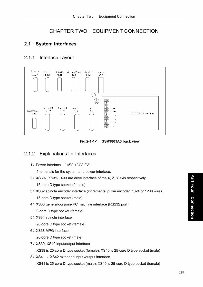
Chapter Two Equipment Connection
215
Part F
ou
r Co
nn
ection
CHAPTER TWO EQUIPMENT CONNECTION
2.1 System Interfaces
2.1.1 Interface Layout
Fig.2-1-1-1 GSK980TA3 back view
2.1.2 Explanations for Interfaces
1)Power interface (+5V. +24V. 0V)
5 terminals for the system and power interface.
2)XS30,XS31,X33 are drive interface of the X, Z, Y axis respectively.
15-core D type socket (female)
3)XS32 spindle encoder interface (incremental pulse encoder, 1024 or 1200 wires)
15-core D type socket (male)
4)XS36 general-purpose PC machine interface (RS232 port)
9-core D type socket (female)
5)XS34 spindle interface
26-core D type socket (female)
6)XS38 MPG interface
26-core D type socket (male)
7)XS39, XS40 input/output interface
XS39 is 25-core D type socket (female), XS40 is 25-core D type socket (male)
8)XS41 ,XS42 extended input /output interface
XS41 is 25-core D type socket (male), XS40 is 25-core D type socket (female)

GSK980TA3 Series turning CNC System User Manual
216
Part F
ou
r Co
nn
ection
2.1.3 Connection Diagram
Fig. 2-1-3-1
2.2 Connection of the System to the Drive Unit
2.2.1 Connection to the Drive Unit
1) Interface diagram of PC side
Fig. 2-2-1-1
2) Definition of the interface signal

Chapter Two Equipment Connection
217
Part F
ou
r Co
nn
ection
1
2
3
4
5
6
7
8
9
10
11
12
13
14
15
1
2
3
4
5
6
7
8
9
10
11
12
13
14
15
XS30: DB15F (X-axis) XS31: DB15F (Z-axis)
XCP+
XDIR+
XPC
+24
XDALM
*XSET
XEN
0V
XCP-
XDIR-
0V
+5V
+5V
0V
0V
ZCP+
ZDIR+
ZPC
+24
ZDALM
*ZSET
ZEN
0V
ZCP-
ZDIR-
0V
+5V
+5V
0V
0V
Fig. 2-2-1-2
2.2.2 Signal Explanation
1. Mono-pulse movement commands signal
XCP+,XCP-,ZCP+,ZCP- are instruction pulse signal, XDIR+,XDIR-,ZDIR+,ZDIR- zre
movement direction signal. Two groups of signals are differential output signals.
Connection diagram is as follows:
Fig. 2-2-2-1
2. Alarm signal of the drive unit (input)
The receive mode of the signal at the system side is as follows. By setting the parameter
(008), it is able to set whether low level “0” or high level “1” is drive unit fault.
Signal Description
nCP+. nCP- Code pulse signal
nDIR+. nDIR- Code direction signal
nPC Zero signal
nDALM Drive unit alarm signal
nEN The system ready signal
nSET Setting signal
CP+
CP-6N137
CNC side

GSK980TA3 Series turning CNC System User Manual
218
Part F
ou
r Co
nn
ection
+24V
R=4.7K
DALM
Fig. 2-2-2-2
3. CNC system ready signal EN (contact output)
Closed contact indicates the CNC system is ready. When the system alarm, the contact signal will be
cut off.
EN
Fig. 2-2-2-3
4. Set signal *SET (output)
When there are movement commands output from the system, it is high level signal. When there is
no movement command output from the system, it is low level signal.
5. Signal PC is used for returning to the reference point
The receive mode of the signal at the system side is as follows.
PC
R=4.7K
Fig. 2-2-2-4

Chapter Two Equipment Connection
219
Part F
ou
r Co
nn
ection
Note 1: If PC signal output by the drive unit is 5V, wire jumper makes SR3028,SR3030,SR3032(510Ω)
on. If PC signal output by the drive unit is 24VV, wire jumper makes SR3027,SR3029,SR3031
(4.7KΩ)on.
Note 2: The user should provide the PC signal, which waveform is as follows.
Reference point return direction
Reference point
Proximity switch is using
(PC)
Encoder PC signal is using
(one turn signal)
Ignore
Deceleration signal
Fig. 2-2-2-5
6) Connection methods for a proximity switch that is taken as a deceleration switch and a zero return
switch.
+24V
2K
+ 24V
proxim ity sw itch
C onnect to *D E C signal
Fig. 2-2-2-6
Note: When this zero return mode is used, ZCX, ZCZ of the parameter should set to “1”.

GSK980TA3 Series turning CNC System User Manual
220
Part F
ou
r Co
nn
ection
2.2.3 Connection Between the System and the Drive Unit

Chapter Two Equipment Connection
221
Part F
ou
r Co
nn
ection
Fig. 2-2-3-1
2.3 Connection to the Spindle Encoder
1024-line or 1200-line incremental position encoder can be used with the system. *PCS,PCS,
*PBS,PBS, *PAS,PAS bellow correspond to Z,Z,B ,B,A ,A respectively.
1
2
3
4
5
6
7
8
9
10
11
12
13
14
15
XS32: DB15F (Spindle encoder)
*PCS
PCS
*PBS
PBS
*PAS
PAS
0V
+5V
+5V
0V
0V

GSK980TA3 Series turning CNC System User Manual
222
Part F
ou
r Co
nn
ection
Fig. 2-3-1
2.4 RS232-C Standard Serial Port (Optional)
The CNC system can communicate with PC machine via RS232-C serial port (Special
communication software shall be installed). Connection diagram is as follows.
XS36 COM1/COM2(9 female D-type plug)
Con
trol
uni
t
DCD
RXD
TXD
DTR
GND
DSR
RTS
CTS
1
2
3
4
5
6
7
8 DCD
RXD
TXD
DTR
GND
DSR
RTS
CTS
1
2
3
4
5
6
7
8
Gen
eral P
C
Signal Explanation
RXD Data receiving
TXD Data sending
Fig. 2-4-1
Note: Weld the shielding layer to the metal of the plug.
Signal Explanation
PAS, *PAS Encoder A-phase pulse
PBS, *PBS Encoder B-phase pulse
PCS, *PCS Encoder Z-phase pulse

Chapter Two Equipment Connection
223
Part F
ou
r Co
nn
ection
2.5 Spindle Interface
XS34 spindle/4th interface DB26 female
101
26
19
13:
12:+24V
11:GND
10:SVC
9:SFR
8:SON
7:ALM
6:M159
5:GND
4:DIR-
3:DIR+
2:CP-
1:CP+
26:M151
25:M153
24:M155
23:M157
22:ZSP
21:COIN
20:PSTO
19:IN35
18:SRV
17:GND
16:+24V
15:
14:
Signal Explanation
Spindle pulse signal
ZSP
4th axis/spindle abnormal alarm
Spindle enable signal
SVC Analog voltage output
Spindle direction signal
CP4+、CP4-
DIR4+、DIR4-
M159
M151
Spindle clamp input
M153
Spindle orientation
M155
M157
SON
SFR、SRV
Zero speed clamp
Speed/pos switch
M157
Spindle CW/CCW
M159
COIN
PSTO
IN35
ALM
Spindle zero speed check
Spindle orientation finish
Spindle speed/pos switch finish
+24V
GND
+24V
0V
918
Input signal cicuit of spindle interface (XS34) :
+24V
+5V
Machineside CNC side
0V
Input signal
1K 10K
Onput signal cicuit of spindle interface (XS34):

GSK980TA3 Series turning CNC System User Manual
224
Part F
ou
r Co
nn
ection
0 V
R e lay
+ 24 V
C N C s id e M a ch in e s ide0V 0V
2.5.1 980TA3 Connection Drawing & Normal Relay
Fig.2-5-1
Note: Weld the shielding layer to the metal of the plug.

Chapter Two Equipment Connection
225
Part F
ou
r Co
nn
ection
2.5.2 980TA3 Connection Drawing & Spindle Driver DAP03(Require
Position & Speed Control Function)
980TA3 match DAP03 spindle signal wire(Dividing pos function)
8
7
6
5
4
3
A+
A-
B+
B-
Z+
Z-
16 PA+
1 PA-
17 PB+
2 PB-
18 PZ+
3 PZ-
DAP03DB44 female
1
2
3
4
22
21
20
CP+
CP-
DIR+
DIR-
ZSP
COIN
12
25
35
11
37
9 SFR
SRV
COM-
STAO
COM+
VP
42
28
33
34
PULS+
PULS-
SIGN+
SIGN-
20
21
ZSP
COIN
PSTO
XS34DB26 male 16
18
17
+24V
0V
XS32DB15 female
24 SON
7 ALM7ALM
8SON
27 ZSL
9
SRV
SFR
25
26
24
M153
M155
M151
Metal shell Metal shell
44 VPO
11
10
GND
SVC
VCMD-15
14 VCMD+
Shield layer
Spindle CW
Spindle CCW
Spindle orientation
Zero speed clamp
Speed/pos switch
Spindle zero speed check
Spindle orien. finish
Speed/pos switch finish
Spindle enable signal
Spindle abnormal alarm
Pulse signal
Direction signal
Analog voltage output
Signal of A phase
Signal of B phase
Signal of Z phase
Fig.2-5-2

GSK980TA3 Series turning CNC System User Manual
226
Part F
ou
r Co
nn
ection
2.5.3 980TA3 Connection Drawing & Spindle Driver GS3000Y-N (Require
Position & Speed Control Function)
Fig.2-5-3

Chapter Two Equipment Connection
227
Part F
ou
r Co
nn
ection
2.6 MPG Interface
XS38 handwheel/MPG interfaceDB26 male Signal Explanation
Signal of MPG A phase
HX X handwheel axial
HU
Increment*1
+5V +5V
0V
0V
HA+、HA-
HB+、HB-
HY
HZ
H*1
H*10 Increment*10
H*100 Increment100
Emergency stop signal *ESP1
+24V +24V
101
26
19 1:HA+
2:HA-
3:HB+
4:HB-
5:HX
6:HY
7:HU
8:HZ
9:H*1
10:0V
11:0V
12:0V
13:0V
14:+5V
15:+5V
16:+5V
17:+24V
18:+24V
19:
20:
21:
22:H*10
23:H*100
24:*ESP1
25:
26:
918
Signal of MPG B phase
Y handwheel axial
U handwheel axial
X handwheel axial
2.6.1 Normal MPG Connection Drawing
Fig.2-6-1

GSK980TA3 Series turning CNC System User Manual
228
Part F
ou
r Co
nn
ection
2.6.2 Connetion drawing of handwheel (match MPG GSKSC10)
Handwheel parameter set:
1. Set No.1 sys parameter BIT3 to be 1, select MPG mode.
2. Set No.7 sys parameter BIT6 to be 1, select external MPG mode.
3. When match row tool post, it is need to set No.81 to be 1.

Chapter Two Equipment Connection
229
Part F
ou
r Co
nn
ection
2.7 Connection of the Power Interface
GSKPB2 power is applied in the systems GSKGSK980TA3, which involves three groups of input
voltage:
Fig. 2-7-1

GSK980TA3 Series turning CNC System User Manual
230
Part F
ou
r Co
nn
ection

Chapter Three I/O Interface of Machine Tool
231
Part F
ou
r Co
nn
ection
CHAPTER THREE I/O INTERFACE OF MACHINE TOOL
3.1 List of the Machine Tool I/O Interface
3.1.1 Standard I/O Interface of GSK980TA3
Fig. 3-1-1-1

GSK980TA3 Series turning CNC System User Manual
232
Part F
ou
r Co
nn
ection
Fig. 3-1-1-2

Chapter Three I/O Interface of Machine Tool
233
Part F
ou
r Co
nn
ection
3.1.2 Expansion I/O Interface of GSK980TA3
Fig. 3-1-2-1

GSK980TA3 Series turning CNC System User Manual
234
Part F
ou
r Co
nn
ection
Fig. 3-1-2-2
Note 1: Various functions can be defined to some of the input and output interfaces, and they are
indicated by “/” sign in the above table.
Note 2: If the output signal is through on to COM, the output function is active. In the contrary
situation, the output function is inactive.
Note 3: If the input signal is through on to +24V, the input function is active. In the contrary
situation, the input function is inactive. When the input signal with “*” sign is through on
to +24V, the input function is inactive. In the contrary situation, the input function is
active.
Note 4: The effectiveness of +24V, COM terminals are equivalent to the CNC power box terminals
that have the same names.
3.2 Input Signal
1) DC input signal A
DC input signal A is the signal from keys, limit switch, contacts of the relay (including DECX,
DECZ,ESP,TCP,ST,SP,DITW,X16, etc.) at the machine side.

Chapter Three I/O Interface of Machine Tool
235
Part F
ou
r Co
nn
ection
a) The contact point at the machine side should meet the following requirements:
Contact capacity: DC30V, 16mA above
Leakage current between contacts in open circuit: 1mA bellow (voltage 26.4V)
Voltage drop between contacts in closed circuit: 24V bellow (current 8.5mA, including
cable voltage drop)
b) Signal loop of this kind of signal is shown in Fig. 3-2-1
+24V
+5V
Machine
side CNC side
0V
Input
signal
1K4.7K
0.1u
0V
Fig. 3-2-1
2) DC input signal B
DC input signal B is the signal from the machine tool to the CNC, which is used at high speed
(T1~T8)
a) The contact point at the machine side should meet the following requirements:
Capacity of the contact: DC30V, 16mA above
Leakage current between contacts in open circuit: 1mA bellow (voltage 26.4V)
Voltage drop between contacts in closed circuit: 24V bellow (current 8.5mA, including
cable voltage drop)
b) Signal loop of this kind of signal is shown in Fig. 3-2-2
+24V
+5V
Machine
side CNC side
0V
Input
signal
1K4.7K
0.1u
0V
Fig. 3-2-2

GSK980TA3 Series turning CNC System User Manual
236
Part F
ou
r Co
nn
ection
3.3 Signal Expalnation
1) Input signal
a) T01~T08 tool number signal
Effective level is low level. When one of the signals is low level signal, it indicates that the tool
post is at this tool number position. Connection is shown as the following figure, 8 external pull-up
resistors are connected.
By setting the parameter NO:9#1, it is able to set tool post in position level signal (0: high level is
effective 1: low level is effective).
+ 2 4 V
T 0 1
T 0 2
T 0 3
T 0 4
T 0 5
C o n tr o l u n i t
2 K * 8
0 V
T 0 8
T 0 6
T 0 7
Fig. 3-3-1
b) TCP:Tool post clamping signal
In the process of tool changing, the system outputs tool post CW signal (TL-) when the tool post
is in position and then begins to check the clamping signal. After receiving this signal, the parameter
P85 setting time is delayed, and the tool post CW signal (TL-) is cut off, T code command is finished,
and the next block is executed. After the system outputs the tool post CW signal, if the system does
not receive TCP in the time set by the parameter P88, the system will issue alarm and cut off the tool
CW signal. If tool post clamping signal is not output from the tool post controller, set parameter NO.9
#0 TCPS to 0 and the tool post clamp signal is not necessary to be connected.
Current tool number is stored at diagnosis P49. The system modifies this value after tool
changing is finished normally. The values at the right corner are the same. After T command is
specified, for some reason these two values are not the same. T displays the number of the specified
tool, while P49 keeps the tool number before tool changing. When the number of specified tool is
consistent with that of P49, tool changing is not performed. Therefore, when the current tool number
is not identical with the one of P49, tool changing should be performed until they are the same.
In manual tool changing, T code and P49 are changed into new value after the tool changing is
finished.

Chapter Three I/O Interface of Machine Tool
237
Part F
ou
r Co
nn
ection
Tool changing sequence diagram:
T1=#082
T2=#088
Tb=#085
Ta<#083* tool number
Tool post CCW output TL+005.6
Tool post CW output TL-005.7
Tool post in-position input ( T4~T1 00.3~00.0)
Tool post clamping input TCP 00.7
Fig. 3-3-2
#83 In the diagram is time parameter set by the corresponding parameter number.
When Ta≥#083 × currently changed tool number, alarm 185 issues: tool changing time
is too long. If CCW rotation from the tool post for Ta (time), the tool position signal is still not
received, alarm occurs.
When Tb≥#088, alarm 186 occurs: Tool post CW rotation locking signal is not
received in the time of tool post CW rotation locking time.
By setting the parameter NO:9#1 TSGN, it is able to set whether high level or low level
is effective for the tool post in position signal (T8~T1).
TSGN 0 : Tool post in-position signal is high level active(normally open)
1 : Tool post in-position signal is low level active(normally closed)
By setting the parameter NO:9#0 TCPS, it is able to set whether high level or low level is
effective for the tool post clamping signal (*TCP).
TCPS 0 : Tool post clamping signal is low level active(normally open)
1 : Tool post clamping signal is high level active(normally closed)
c) DECX, DECZ deceleration switch signal
The signal is a normally-closed contact, which is used in mechanical reference return. The
process of the reference return is as follows:
After selecting the mechanical origin mode, then press the manual feed key of the
corresponding axis, and the machine tool will move to the reference point at rapid traverse
speed. When reference return deceleration signal (DECX. DECZ ) contact is disconnected
(press down the deceleration switch), the feed rate is decelerated immediately. Then the
machine tool moves at the regular low speed [set by the parameter P43. When the
deceleration switch is released, the deceleration signal contact is closed again. In addition,
CNC begins to detect the encoder one-turn signal or magnetic switch signal (PC signal). If
this signal is high level, the motion will be halted. In addition, the corresponding zero return

GSK980TA3 Series turning CNC System User Manual
238
Part F
ou
r Co
nn
ection
indicator on the operation panel lights up for machine zero return completion. Manual feed
is always inactive before the zero return key is released.
Reference return direction of each axis can be set by the parameter. The connection
diagram is as follows:
+24V
Control unit
DECX
DECZ
Fig. 3-3-3
d) The functions of automatic cycle start signal ST and feed pause are the same as that of
the system panel. When NO:14#0 MST=0,NO:14#1 M@SP=0, signal ST and SP are
active, otherwise, the signal of this point is empty. When NO:14#1 M@SP=0, external feed
hold switch is necessary, otherwise, feed hold signal will be active all the time.
+24V
Input port
SP
ST
No lock normally close point
Fig. 3-3-4
e) ESP signal
This signal is a normally-closed signal. When the contact is disconnected, the control
system resets, and the machine tool stops urgently. After the emergency stop, the system
ready signal EN will be disconnected. At the same time, motion command output is
blocked.
The system is designed with software limit function to perform overtravel check. It is
unnecessary to fix a limit switch for overtravel checking. However, when the drive unit
fault occurs, the motion of the machine tool exceeds the software limit zone. In order to
stop the machine tool, a stroke limit switch is necessary. Its connection figure is as
follows:

Chapter Three I/O Interface of Machine Tool
239
Part F
ou
r Co
nn
ection
+X -X +Z -Z
Overtravel released switch
+24V
*ESP
Emergency stop switch
Fig. 3-3-5
When the connection in the above figure is used, if the parameter NO:14#3 MESP=0 is set to
1, the above function is not active. The emergency signal (*ESP)explanted here is standard
connection. This connection method should be used as far as possible when users connect
the signal.
f) Hardware limit signal LIMITZ, LIMITX
This signal is a normally open signal. When the contact is disconnected, the control
system resets, and the machine tool stop urgently. After the emergency stop, the system
hardware limit alarm occurs. At the same time, motion command output is blocked.
When this function is active, the hardware limit of each axis can be separated from ESP,
and limitation of each axis will be reflected correctly.
When this function is used, the parameter NO:8#2 LMTX. NO:8#3 LMTZ should be set to
1. If it is set to 0, the function is not active. Moreover, by setting NO:8#4 LTVX. NO:8#5
LTVZ, it is able to set the signal is high level active or low level active. When it is active at
high level, the alarm occurs when the signal is through on to +24V. When it is active at low
level, the alarm occurs when the signal is through on to 0V. When the alarm occurs, enter
into the manual mode, move the overtravel axis reversely. The alarm will be released
when the axis departs from the stroke switch.
g) External alarm signal OW1, OW2
This signal is normally open contact signal. When the contact is connected, the control
system resets, making the machine tool stop urgently. After the emergency stop, the
external alarm occurs in the system. At the same time, motion command output is
blocked.
This signal is an optional one, which can be used as required.
When this function is used, the parameter NO:12#6 WAR1. NO:12#7 WAR2 should be
set to 1. If it is set to 0, the function is not active. Moreover, by setting NO:12#3 WA2.
NO:12#2 WA1, it is able to set the signal is high level active or low level active. When it is
active at high level, the alarm occurs when the signal is through on to +24V. When it is
active at low level, the alarm occurs when the signal is through on to 0V. When the alarm
occurs, operation can be performed after reset.

GSK980TA3 Series turning CNC System User Manual
240
Part F
ou
r Co
nn
ection
h) SPEN, SAR feed and spindle enable input signal
These two signals are normally open signals. When SAR contact is closed, spindle can be
started and the cycle start can be performed. When SPEN contact is closed, spindle can
be started while the cycle start can not be performed. If these two contacts are
disconnected, the spindle can not be started, and the cycle start can not be performed
either.
When the spindle is rotating, if disconnect both signals, the spindle will stop immediately.
After one contact is connected, the CNC starts the spindle automatically, restoring the
previous speed.
If the SPEN signal is disconnected in program execution, the CNC in feed hold status.
After SAR signal is closed, the current program can be performed by pressing cycle start
key.
The function is active when the parameter NO:15#1 SPEN is set to 1. If it is set to 0, the
function is not active.
i) Safety door detection signal DOOR
This signal is a normally closed signal. The system resets when the contact is
disconnected, which makes the machine tool stop urgently. After the emergency stop, the
alarm that the safety door is not closed occurs in the CNC. At the same time, motion
command output is blocked.
This function is active when the parameter NO:16#5 SFDR is set to 1. The CNC can not
run if the safety door is open, the door should be closed in operation.
When the parameter is set to 0, CNC does not check whether the safety door is closed or
not. By setting parameter NO:16#6 SFDV, it is able to set the signal is high level active or
low level active. When it is high level active, the safety door is closed when the signal
connects to +24V. However, the alarm is issued when the signal is disconnected or it
connects to 0V. When it is low level active, the safety door is closed when the signal
connects to 0V. However, the alarm is issued when the signal connects to +24.
This function is active in Auto mode, safety door is not detected in other modes.
j) PCH Pressure check signal
This signal is normally closed contact signal. The system resets when the contact is
disconnected, which makes the machine tool stop urgently. After the emergency stop, low
pressure alarm occurs in the CNC. At the same time, motion command output is blocked.
This function is active when the parameter NO:16#4 PSCK is set to 1. The CNC can not be
started normally if the pressure is low. By setting the parameter NO:16#3 PSCV, it is able
to set the signal is high level active or low level active. When it is high level active, the
signal is through on to +24V, which indicates the pressure reaches the specified value. If
the signal is disconnected with +24V or connected to 0V, the alarm is issued. When it is

Chapter Three I/O Interface of Machine Tool
241
Part F
ou
r Co
nn
ection
low level active, the signal is through on to 0V, which indicates the pressure reaches the
specified value. The alarm is issued when the signal is through on to +24V.
When this function is active, once the low pressure alarm is detected and the signal hold
time exceeds the value set by the parameter P92, the alarm is issued in CNC. At this time,
the axis feed and spindle stop, automatic cycle can not be started, cooling and lubricant are
cut off. The alarm can be released by resetting or powering off.
k) GR1, GR2 Gear in-position signal
This signal is normally open contact signal. See 3.5 for the functions.
l) Expansion user input signal
The system added two user defined input signals.
Code format: M91
M92
M93
M94
Input points correspond to the codes M91, M92, M93, M94 are not defined. User can define
it as required.
M91, M92 correspond to user defined input point 1. M93, M94 correspond to user defined
input point 2. If status of the input points conform to the one specified by the codes, the next
block is executed sequentially. If not, it will wait.
M91 code detects input status of the user 1. It waits (input terminal connects with 0V) until
input is inactive.
M92 code detects input status of the user 1. It waits (input terminal disconnects with 0V)
until input is active.
M93 code detects input status of the user 2. It waits (input terminal connects with 0V) until
input is inactive.
M94 code detects input status of the user 2. It waits (input terminal disconnects with 0V)
until input is active.
3.4 Output Signal
1) Output signal
DC output signal is used for driving the relay and indicator at the machine tool side. Transistor
is used in drive circuit, which includes: S1~S4, M3, M4, M5, M8, DOTWJ(M10), DOTWS
(M11), DOQPJ(M12), DOQPS(M13), M32, TL-, TL+, SPZD, M51~M70.
a)Specifications of the transistor used for outputting
① Maximum load current when output is ON:below 200mA including transient current.
② Saturation voltage when output is ON: Max. value is 1.6V when the current is

GSK980TA3 Series turning CNC System User Manual
242
Part F
ou
r Co
nn
ection
200mA.Typical value is 1V.
Withstand voltage when output is OFF: below 24+20% including transient current.③
④ Leakage current when output is OFF: below 100μA.
b) Output circuit
C N C s id e
0 V
R e l a y
+ 2 4 V
Fig. 3-4-1
All output signals for this system are provided by Darlington tube. Corresponding
Darlington tube is connected when output is active. Except for pulse signals (non output
hold) TL-, TL+, SPZD, others are level signals (output hold), the common port of the signal
is +24V.
2) Explanation of output signal
a) S1~S4 Spindle speed switching value control signal
Share an output port with M41~M44. When spindle gear control is selected, S1, S2
(second gear) or S1~S4 (fourth gear) functions are active.
Only one signal in S1~S4 is active.
b) TL+, TL-tool change signal
TL+ is CCW tool change signal, TL- is CW tool change signal.
c) M03,M04,M05 are spindle control M code.
M03 is for spindle CCW rotation, M04 is for spindle CW rotation, M05 is for spindle stop.
d) M08,M09 (no internal signal output) cooling control.
M08 is for cooling ON. M09 is for cooling OFF.
e)DOTWJ, DOTWS are tailstock control switches. DOTWJ: tailstock advance. DOTWS:
tailstock retreat. See 3.7 for details.
f) DOQPJ, DOQPS are for chuck clamp control. DOQPJ is for chuck clamp. DOQPS is for
chuck unclamp.
DOQPJ shares an output port with Y16 and DOQPS. DOQPJ is for chuck clamp. DOQPS
is for chuck unclamp. The function is active when automatic chuck control is selected. It is
reverse in outer chuck mode. See 3.6 for details.
g) M32,M33 (no internal signal output) lubricant control

Chapter Three I/O Interface of Machine Tool
243
Part F
ou
r Co
nn
ection
M32 is for lubricant ON. M33 is for lubricant OFF. When NO:13#2 JLB is set to 0, oil is
supplied continuously for the system. If it is set to 1, oil is supplied intermittently for the
system. Oil supply time is set by the parameter P107. Intermittence time is set by the
parameter P108.
h) SPZD Spindle brake signal SPZD
Action relationships are as follows:
T2T3
Spindle rotation (CW/CCW )
Spindle stop
Spindle brake
Fig. 3-4-2
T2 is delay time from outputting spindle stop signal to outputting spindle break signal. It is
set on the parameter number P89.
T3 is the holding time of the spindle brake, which is set on the parameter P90.
i) STAR/TRIAN Star triangle start signal STAR/TRIAN
It is active when parameter NO:15#7 STAR is set to 1. STAR signal output is active after
the spindle is started. The time set by the parameter P93 is delayed, signal STAR is off and
TRIAN signal is output.
Signal of spindle rotation(CW/CCW) Time set by the parameter
Star-type start signal
Triangular-type start signal
Fig. 3-4-3
j) WARN Output alarm signal WARN
It is active when the parameter NO:15#6 OWAR is set to 1. The signal is active if alarm is
issued in the CNC. After the alarm is cancelled, this signal is inactive. The signal is used
for warning customers that CNC is in alarm state.
k)Processing completion signal M30
It is active when the parameter NO:15#5 OM30 is set to 1. After the system is powered on
or M30 is executed, the system is in work completion state. At this time, the signal is active.
When the CNC is processing automatically or it is running, the signal is inactive. This signal
is used for warning customers that CNC is in processing completion state or in standby
state.

GSK980TA3 Series turning CNC System User Manual
244
Part F
ou
r Co
nn
ection
l) Auto run signal STM
It is active when the parameter NO:15#4 OMST is set to 1. When the system runs
automatically, the signal outputting is active. It is inactive after M30 is executed or after
reset.
WARN, M30 and OSTM are interlocked with each other. They respectively indicate alarm,
standby and processing state. These signals are mainly used for controlling of the
machine tool state indicators.
m) TLOCK Tool post clamp signal
The signal is active when Taiwan LIO SHING tool post is used. Please refer to the
appendix 6 for details.
n) Expansion M code
The system is added 10 user defined output ports that controlled by M51~M70
respectively. Odd commands make the signal active, and even number of commands
make the signal inactive. Long signal is output in execution. The specific definitions are as
follows:
M51 code makes output of the No. 1 user output point active (output low level)
M52 code makes output of the No. 1 user output point inactive (output high level)
M53 code makes output of the No. 2 user output point active (output low level)
M54 code makes output of the No. 2 user output point inactive (output high level)
M55 code makes output of the No. 3 user output point active (output low level)
M56 code makes output of the No. 3 user output point inactive (output high level)
M57 code makes output of the No. 4 user output point active (output low level)
M58 code makes output of the No. 4 user output point inactive (output high level)
M59 code makes output of the No. 5 user output point active (output low level)
M60 code makes output of the No. 5 user output point inactive (output high level)
M61 code makes output of the No. 6 user output point active (output low level)
M62 code makes output of the No. 6 user output point inactive (output high level)
M63 code makes output of the No. 7 user output point active (output low level)
M64 code makes output of the No. 7 user output point inactive (output high level)
M65 code makes output of the No. 8 user output point active (output low level)
M66 code makes output of the No. 8 user output point inactive (output high level)
M67 code makes output of the No. 9 user output point active (output low level)
M68 code makes output of the No. 9 user output point inactive (output high level)
M69 code makes output of the No. 10 user output point active (output low level)
M70 code makes output of the No. 10 user output point inactive (output high level)

Chapter Three I/O Interface of Machine Tool
245
Part F
ou
r Co
nn
ection
3.5 Spindle Automatic Gearing Control
When spindle frequency conversion is selected (0~10V analog voltage output), automatic spindle
mechanical gear shifting is available for 4 gears. By setting parameter P55~P58 based on gears,
making the speed of S code is consistent with the actual speed.
Relevant parameter:bit parameter NO:01#4:
0 0 1 MDSP
MDSP =1: Spindle is analog volume control.
=0: Spindle is other mode.
Bit parameter P NO:10#3. 4. 6. 7:
0 1 0 AGER AGIN AGIM SPT TRD G0&T TSS
AGER =0: Spindle automatic gearing is inactive.
=1: Spindle automatic gearing is active.
AGIN =0: Not detect in-position signal when shifting to gear 1,2.
=1: Detect in-position signal when shifting to gear 1,2.
AGIM =1: Gear in-position signal is high level active.
=0: Gear in-position signal is low level active.
SPT =1: Spindle jog in auto mode is active.
=0: Spindle jog in auto mode is inactive.
Input/output signal:
GR1: Gear 1 in-position signal
GR2: Gear 2 in-position signal
Note 1: There are no gear 3, 4 in-position signals.
M41~M44:1~4 gear shifting output (Share a common port with S1~S4)
① Check whether the AGER of the parameter is 1 and analog spindle function is selected,
otherwise, alarm 180 (M41~M44 can not be used when spindle is in gear control or
spindle automatic gearing control is inactive) is issued.
② Check whether it is consistent with the current gear (check output state). No gearing is
done if the specified gear is consistent with the current gear. If not, gear shifting will be
performed based on the process .③
③ Set the spindle speed to the one specified by the parameter 066. If there is motion, stop
it temporarily.
④ After a delay (gear shifting time 1) by the parameter 063, turn off the original gear output
signal and output the new gearing signal.

GSK980TA3 Series turning CNC System User Manual
246
Part F
ou
r Co
nn
ection
⑤ If the gear is 1 or 2, and the parameter 010 AGIN is 1, it jumps to , or else it jumps to ⑥
.⑦
⑥ Check the gear in-position input signal (By setting parameter 010 AGIM, it is able to set
level is active at 0 or 1) of gear 1or 2, it jumps to if the gear in⑦ -position is done.
⑦ After a delay (gear shifting time 2) by the parameter 064, output spindle analog voltage
by the current gear according to a value set by parameter P055~P058 (correspond to
gear1~4) and finish the gearing.
Note 2: M40 cancels M41~M44 function output. S0 cancels S1~S4 function output.
Note3: Gearing signal M41~M44 is not output when power on. Default gear is 0.
3.6 Chuck Control (Chuck Detection Function)
1.Relevant signal:bit parameter NO:15#3;NO:16#0. 1. 7:
KPDW =1: Check chuck in-position signal.
=0: Not check chuck in-position signal.
NWKP =1: Outer chuck mode.
=0: Inner chuck mode.
SLSP =1: Check whether the chuck is clamped when the spindle is started
=0: Not check the chuck state when the spindle is started
SLQP =1: Chuck function is active
=0: Chuck function is inactive
2. Input/output signal:
NQPJ: Inner chuck clamping in-position/outer chuck unclamping in-position signal
WQPJ: Inner chuck unclamping in-position/outer chuck clamping in-position signal
DIQP: Chuck clamping/unclamping input. It is usually controlled by the foot-switch
DOQPS Chuck unclamping output
DOQPJ:Chuck clamping output
3. Action time sequence:
1)When SLQP=1, SLSP=0 and KPDW=0, it only controls the clamp or unclamp of the chuck,
but not decides whether the chuck clamping in position or not.
2) When SLQP=1, SLSP=1and KPDW=0, it can not be started if the chuck is not clamped.
(Alarm 044, start the spindle before the chuck is clamped)
0 1 5 KPDW
0 1 6 NWKP SLSP SLQP

Chapter Three I/O Interface of Machine Tool
247
Part F
ou
r Co
nn
ection
DIQP
DOQPJ
DOQPSOutput signal
Output signal
Input signal
Fig. 3-6-1
DOQPS:Chuck unclamping output; DOQPJ:Chuck clamping output
DOQPJ and DOQPS output high resistance at power on. When CNC detects that the chuck
input signal DIQP is active for the first time. DOQPJ(pin 4 of XS39)outputs 0V, chuck is
clamped.
After M12 is executed, DOQPS(pin 10 of XS39)outputs high resistance. DOQPJ(pin 4 of
XS39)outputs 0V, and chuck is clamped.
After M13 is executed, DOQPJ(pin 4 of XS39)outputs high resistance. DOQPS(pin 10 of
XS39)outputs 0V, and the chuck is unclamped.
Note: CNC judges whether M12 is input. If M12 is not input, the system alarms when the spindle is
started.
3)When SLQP=1, SLSP=1, NWKP=1, KPDW=1, CNC chooses outer chuck mode, and chuck
in-position signal detecting is active:
DOQPS:chuck clamping output, WQPJ:clamping in-position signal
DOQPJ:chuck unclamping output, NQPJ:unclamping in-position signal
DOQPJ and DOQPS output high resistance at power on. When CNC detects that the chuck
input signal DIQP is active for the first time. DOQPS outputs 0V, chuck is clamped.
After M12 is executed, DOQPS outputs 0V. DOQPJ outputs high resistance, chuck is
clamped and CNC waits for WQP signal to be in-position..
After M13 is executed, DOQPJ outputs 0V. DOQPS outputs high resistance, the chuck is
unclamped and CNC waits for NQPJ signal to be in-position.
As the second chuck input is active, DOQPS outputs 0V, chuck is unclamped. The chuck
clamping/unclamping signal is output alternatively, i.e. the output state is changed each
chuck input signal is active.

GSK980TA3 Series turning CNC System User Manual
248
Part F
ou
r Co
nn
ection
Fig. 3-6-2
Note: CNC detects clamping in-position signal altered it is clamped. If there is no clamp signal input,
CNC alarms.
4)The interlock of the chuck and the spindle:
When SLQP=1, SLSP=1, M3 or M4 is active, alarm is issued if M13 is executed and the output
is unchanged.
When SLQP=1, SLSP=1, KPDW=1, if M12 is executed in MDI or Auto mode, CNC does not
execute next code till it detects the chuck clamping in-position signal is active. When the chuck
input signal DIQP is active in Manual mode, the panel spindle CCW, CW keys are inactive till it
detects the chuck clamping in-position signal is active. In spindle running or auto cycle
processing, DIQP input signal is inactive. DOQPS, DOQPJ are held on at CNC reset and
emergency stop.
When SLSP=0, KPDW=1, it does not detect whether the chuck is clamped or not. However,
when chuck clamp/unclamp in-position command is executed, action is finished till in-position
signal is detected. (It must be careful to use this mode)
Note 1: DOQPJ and DOQPS output 0. DOQPJ outputs 1 when chuck input signal is active for the 1st
time.
Note 2: DIQP is inactive in spindle running or auto cycle processing.
3.7 Tailstock Control (Tailstock hierarchical advance/retreat control)
1. Relevant parameter:bit parameter NO:15#3:NO:16#2:
0 1 5 WZ2
0 1 6 SLTW
SLTW =1:Tailstock function is active
=0:Tailstock function is inactive

Chapter Three I/O Interface of Machine Tool
249
Part F
ou
r Co
nn
ection
WZ2 =0:Tailstock hierarchical advancing/retracing function is inactive
=1: Tailstock hierarchical advancing/retracing function is active
2. Input/output signal:
DITW: Tailstock clamping/unclamping input
DOTWJ: Tailstock clamping output signal
DOTWS: Tailstock unclamping output signal
DOTWJM:Tailstock slow advancing output signal
DOTWJJ: Tailstock lock output signal
WZ1J: Tailstock slow advancing detection input signal
WZ2J: Tailstock in-position detection input signal
3. Action time sequence:
1)When SLTW=1, WZ2=0,
DITW:Tailstock clamping/unclamping input
M10/M11 is tailstock clamping/unclamping control signal respectively.
After M10 is executed, DOTWS outputs high resistance, DOTWJ outputs 0V, and tailstock
advances.
After M11 is executed, DOTWJ outputs high resistance, DOTWS outputs 0V, and tailstock
retreats.
Fig. 3-7-1
2)When SLTW=1, WZ2=1, S3/S4/M43/M44 function is inactive. If the command is executed,
CNC will issue alarm: illegal command. Maximum tools number is 4.
After M10 is executed, CNC DOTWS outputs high resistance, DOTWJ outputs 0V, and
tailstock advances rapidly. When WZ1J signal is active, DOTWJ outputs high resistance,
DOTWJM outputs 0V, tailstock advances slowly. When WZ2J signal is active, DOTWJM
outputs high resistance, DOTWJJ outputs 0V, tailstock is locked and tailstock advancing is
finished.
After M11 is executed, DOTWJJ outputs high resistance, tailstock is unclamped. DOTWS
outputs 0V, tailstock retreats rapidly, and the tailstock retreat is finished.

GSK980TA3 Series turning CNC System User Manual
250
Part F
ou
r Co
nn
ection
Fig. 3-7-2
Note 1: DOTWJ and DOTWS output 0 when power on. DOTWJ outputs 1 when chuck input signal is active
for the 1st time.
Note 2: DITW input is inactive in spindle running or auto cycle processing.
3.8 External Program Lock
External program lock is an external key switch, which is used to prevent work programs from
altering.
Relevant:bit parameter NO:13#6. #7:
0 1 3 PLCKV PLCK
PLCKV =1:Program lock is high level active
=0:Program lock is low level active
PLCK =1:Program lock function is active
=0: Program lock function is inactive
Input/output signal:
PROLOCK:External program lock
+24V
PROLOCK
Fig. 3-9-1

Chapter Three I/O Interface of Machine Tool
251
Part F
ou
r Co
nn
ection
3.9 External Feed Pause and Spindle Pause
External feed pause and spindle pause is a three-phase code-chosen-switch. They are used to
stop program in auto running or stop the spindle. When the three-phase is on the normal position, the
modes “press reset key again” or “execute program directly” can be selected.
Relevant parameter:bit parameter NO:15#0. #1:
0 1 5 SPEN SPENC
SPEN =1:Feed and spindle enable input are active
=0:Feed and spindle enable input are inactive
SPENC =1: Feed and spindle control
=0: Spindle control
Note: When SPENC and SPEN are set to 0, spindle enable function is inactive. When SPENC is set to 0,
SPEN is set to 1, spindle enable function is active. When SPEN signal of the input port is high
level, the spindle can be started by the CNC. When SPENC and SPEN are set to 1, SAR of the
input port is high level input, the spindle can be started by the CNC and feed is enabled. When
SPEN signal is high level, spindle is enabled, while feed is forbidden. When SAR and SPEN are
not connected to +24V, spindle rotation and feed are forbidden.
Input/ output signal:
SAR: External feed hold
SPEN: External spindle hold
This function has three connection states:
+24V
SAR
SPEN
Three-digit switch is in the right, feed and spindle is normal
Fig.3-9-1

GSK980TA3 Series turning CNC System User Manual
252
Part F
ou
r Co
nn
ection
Fig.3-9-2
+24V
SAR
SPEN
Three-digit switch is in the left, feed and spindle is paused
Fig.3-9-3
3.10 I/O Signal Disgnosis List
All I/O signals of the system are described in this diagnosis list.
1) List of the signals from machine tool to CNC
7 6 5 4 3 2 1 0001
002
003
004
X 1 7 X1 6 X 1 5 X 1 4 X 1 3 X1 2 X1 1 X 1 0
TC P D IQ P *D EC X D ITW *SP ST D EC Z * ESP
T 8 T7 T6 T5 T4 T3 T2 T1
SA R LTZ LTX SPEN PSC K D O O R G R2 G R1
LC K O W A2 O W A1
X S3 9: 1 2 X S3 9 : 1 1 X S4 0: 1 X S4 0: 2 X S4 0: 7 X S4 0: 8 X S4 0 : 9 X S4 0 : 1 0
X S4 0: 1 9 X S4 0: 2 0 X S4 0: 2 1 X S4 0 : 2 2 X S4 0: 3 X S4 0: 4 X S4 0: 5 X S 4 0: 6
N o.
So ck et p in N o.

Chapter Three I/O Interface of Machine Tool
253
Part F
ou
r Co
nn
ection
2) List of the signals from CNC to machine tool
006 X 27 X 26 X 25 X24 X 23 X22 X 21 X 20
TL- TL+ M 13 M11 S04/M 44 S 03/M 43 S02/M 42 S 01/M 41
005 Y 17 Y 16 Y 15 Y14 Y 13 Y12 Y 11 Y 10
SPZD M 12 M 05 M32 M 08 M 10 M 04 M03
7 6 5 4 3 2 1 0
X S39:17 X S39 : 4 X S39:16 X S39: 6 X S39:15 X S39: 2 X S39:3 X S39: 7
N o.:
Diagnosis No.
Socket p in No.
Socket p in No.
X S40:13 X S 40:12 X S39: 10 X S39: 9 X S39: 8 X S39:14 X S39: 1 X S39: 5
3.11 Function Description
In diagnosis page, 【machine panel】 interface is shown as figure 3-12-1:
OPERATOR O0001 N0000
MLK(KEY1): *OFF ON
AFL(KEY2): *OFF ON
SBK(KEY3): *OFF ON
DRN(KEY4): *OFF ON
BDT(KEY5): *OFF ON
POSITION(RELATIVE)
U 0.000
W 0.000
Message 10:13
Axis Rev 0000
Tool No 0100
Fact Rate 0
Cool Mes OFF
Axis Mes Stop
G00 G98 G97 G40
MDI
Fig. 3-12-1
On machine panel page, 1, 2, 3, 4, 5 keys are used to shift machine lock, M.S.T. lock key, single
block, dry run, block skip switch. Their functions are the same as that of the keys , ,
, , .

GSK980TA3 Series turning CNC System User Manual
254
Part F
ou
r Co
nn
ection

Chapter Four Machine Tool Debugging
255
Part F
ou
r Co
nn
ection
+X -X +Z -Z
Overtravel released switch
+24V
*ESP
Emergency stop switch
CHAPTER FOUR MACHINE TOOL DEBUGGING
The debugging and trial run methods and steps are described in this chapter. The
corresponding operations can be performed after debugging by the following steps.
4.1 Debugging Preparation
Debug the system according to the following steps:
CNC connection: correct connection is the foundation on which debugging is performed
smoothly;
Drive unit parameter setting: set motor type parameter, control mode setting;
CNC parameter setting: control parameter, speed parameter setting.
4.2 System Power On
Switch on air break switch in the electric cabinet.
Connect to the air break controlling DC 24V or fuse, and check whether DC24V power is
normal.
Check whether the other power is normal.
Turn on the CNC system.
4.3 Emergency Stop and Limit
This system has software limit function. It is suggested that hardware limit is employed by fixing
the stroke limit switches at the positive or negative directions of the axis. The connection is shown as
follows:
Fig. 4-3-1
ESP signal can be shielded by parameter NO:14#3 MESP
When MESP=1, emergency stop is inactive. It is for debugging.

GSK980TA3 turning CNC System User Manual
256
Part F
ou
r Co
nn
ection
When MESP=0, emergency stop is active. It can be used normally.
Diagnosis NO:01#0 can be used to check whether the emergency signal is input or not. If it is set
to 1, which indicates that the emergency stop switch is connected (switching signal is normally closed
signal).
In Auto mode or MPG mode, slowly move the axes to testify the activity of the stroke limit switch,
correctness of the alarm display, activity of the overtravel release button. When overtravel occurs or
emergency stop button is pressed, alarm 254 “the system is not ready” will be issued by CNC system.
Press the overtravel release button on the panel and move the axis reversely until it detaches the
stroke switch, the alarm will be eliminated.
4.4 Drive Axis Debugging
1)Drive unit alarm
If X-axis or Z-axis drive unit alarm displays when power on, user must first check whether the
drive unit alarm indicator is lighted up or not (for stepping drive unit) or check whether the
alarm is displayed (for servo drive unit). If alarm occurs in drive unit, process the drive unit first,
and then check whether the drive alarm line is cut off or not. If none above phenomenon
occurs, the reason is that the level set by alarm parameter does not match the drive unit.
Therefore, alter #0 and #1 the parameter NO:8 (ALMX and ALMZ correspond to X and Z axes
respectively). After the parameter alteration, press key to eliminate drive unit alarm.
2)Direction adjustment of the driving motor
If operation direction of the drive unit is inconsistent with coordinate direction of the computer,
alter #0 and #1 the parameter NO:7#0 (DIRX and DIRZ correspond to X and Z axes
respectively) or change direction selection switch of the transformer drive unit.
4.5 Gear Ratio Adjustment
1)Formula
CMR:Command multiplier coefficient [Parameter P17~18]
CMD:Command frequency division coefficient[Parameter P19~20]
a:Stepping angle (degree)
L: Movement amount corresponds to the step motor rotating one turn(mm)
Example: Z axial motor is connected directly. Screw pitch of the lead screw is 6mm. X axial
reduction ratio is 3/5. Screw pitch of the lead screw is 4mm. Its servo gear ratios are as follows:
calculating method for X axis: 4×2500×3/(4×1000×5)=3/2 that is, command multiplier coefficient of

Chapter Four Machine Tool Debugging
257
Part F
ou
r Co
nn
ection
the X axis=3, command frequency division coefficient of the X axis =2. Calculating method for Z axis:
4×2500/(6×1000)=5/3, that is, command multiplier coefficient of the Z axis=5, command frequency
division coefficient of the Z axis =3. This gear ratio can be set to the drive unit. When stepping drive
unit is used, its stepping angle is as follows:
X axis: 360×5/(4000×3)=0.15, Z axis: 360/6000=0.06.
4.6 Rapid Traverse Rate and Linear ACC&DEC Adjustment
Parameter number P21, P22 respectively set the rapid traverse rate scope (30 mm/min~
30000mm/min)of the X and Z axes.
Parameter number P23, P24 respectively set the linear ACC&DEC time constant scope (8~
4000)of the X and Z axes in rapid traverse.
Parameter number P25, P26 respectively set the S-shape time constant value setting scope
(8~4000)of the X and Z axes in rapid traverse.
Parameter number P28 is lower value of the ACC&DEC low speed in cutting feed (0~
500mm/min).
Parameter number P29, P30 are S acceleration/deceleration time constant in cutting feed, which
scope is 8~4000.
Parameter number P31 are linear acceleration/deceleration time constant in cutting feed, which
scope is 8~4000.
Note: When stepping drive unit is used, it is suggested that ACC&DEC time constant are bigger than or
equal to 300. When servo drive unit is used, the value can be set to 100.
4.7 Upper Speed of the Cutting Feed
Parameter P27 is used to set the upper speed of the cutting feed. It must be set to 8000.
4.8 Adjustment for Thread Machining
1)Adjustment for thread run-out width
Parameter P68 THDCH is used to set thread run-out length. Chamfering width =THDCH*1/10*
screw pitch.
2) Threading exponential acceleration and deceleration
Parameter P69 is linear ACC&DEC constant of two axes in threading. It is usually set to 100.
Parameter P157 is ACC&DEC time constant of the shorter axis in thread run-out.
Parameter P158 is maximum speed of the shorter axis in thread run-out.

GSK980TA3 turning CNC System User Manual
258
Part F
ou
r Co
nn
ection
3) Spindle setting
Parameter P59 is for threading is performed after percentage is stable.
Parameter P59 is spindle speed sampling period (×4ms).
4.9 Machine (mechanical) Zero Adjustment
Users have to make sure that zero-return deceleration switch is connected correctly. It can be
checked by diagnosis NO:1#5 DECX and NO:1#1 DECZ. Make sure that zero point signal is linked
correctly. It can be checked by diagnosis NO:9#0 PCX and NO:9#1 PCZ. If it is right, this digit will be
changed into 1 after the motor rotates once.
Parameter NO:6#4. 5(ZCX and ZCZ correspond to X and Z axes respectively)are used to set the
type of the zero return. They are usually set to 0. For the detailed explanations, please refer to
machine zero return, chapter 8.
Parameter NO:5#1. 2(ZMX and ZMZ correspond to X and Z axes respectively)are used to set
direction of zero return. They are usually set to 1, Which indicates CCW zero return.
4.10 Offset between Lead Screws
Parameters P36, P37 are offset between lead screws of the X, Z axes. Thereinto, No.36 is
diameter value.
Backlash compensation should be detected by dialgaug, clock gauge or laser detector, it does’t
recommend to be detected by handwheel or single-step mode, because backlash compensation only
compensate accuratly can improve the precision of processing, it is suggest to use the following
method:
Edit program:
O0001;
N10 G01 W10 F800;
N20 W15 ;
N30 W1 ;
N40 W-1 ;
N50 M30 。
Backlash compensation value (No.36,37) should be set to 0 before measuring;
Single segment to run the program, find measure basis A after twice positioning, record
current data. Run 1mm in the same direcition, then run 1mm to point B reverse to read
current data.

Chapter Four Machine Tool Debugging
259
Part F
ou
r Co
nn
ection
Fig.4-4 Backlash measure method drawing
Backlash error compensation value= | data record from point A –data record from point A
| ;input the count result to system parameter No.036(BKLX) or NO.037 (BKLZ).
Data A :data of dial indicator read at point A;
Data B :data of dial indicator read at point B;
pulse equivalent: 1 mu
Note 1:system parameter No.033 can set frequency of backlash compensation.
Note 2:backlash compensation should be rechecked after the machine tool has been used for 3
months.
4.11 Electronic Toolpost Debugging
Make sure the cable of tool number input signal is connected correctly. It can be checked by
NO:2#1~7(T01~T08). When it is right, in-position signal displays 0. Otherwise, in-position signal
displays 1. (In-position signal displays 1, and it displays 0 for other situations)
Diagnosis NO:6#6. 7(TL-. TL+)can be used to check whether toolpost CCW/CW rotation signals
are correct in tool changing.
The following parameters should be set correctly to ensure the toolpost runs normally.
Parameter NO:9=00001110 (BIT0=1 indicates toolpost clamping is high level active, BIT0=0
indicates toolpost clamping is low level active. BIT1=1 indicates toolpost clamping is low level
active,BIT1=0 indicates toolpost clamping is high level active)
Parameter P81=4: Total tool number selection
Parameter P82=10: Tool changing time T1 (x4ms)
Parameter P83=1000: Upper time for moving a tool in tool changing
Parameter P84=15000: Upper time from changing the 1st tool to changing the last tool
Parameter P85=200 : Tool post CW clamping time (x4ms)
Parameter P88=500: Alarm time of not receiving *TCP signal
Reading data position
A
B
Reverse direction

GSK980TA3 turning CNC System User Manual
260
Part F
ou
r Co
nn
ection
4.12 Spindle Adjustment
When converter controls the spindle, parameter NO:1#4=1. When the spindle is not controlled by
converter, parameter NO:1#4=0.
The system could be equipped with 1024 or 1200-line encoder (outputting A, A , B, B , Z, Z
signal), which can be set by parameter P52 . When drive ratio between the spindle and encoder is
not 1: 1, it can be adjusted by setting the gear number between spindle and encoder with
parameter P53, P54 .
Diagnosis NO:9#2 PCS could be used to check screw head signal of the spindle encoder.
When the converter controls the spindle, adjust value of parameter P55 to make input rotational
speed command (S command) is consistent with the actual speed.
Parameter P89 is the time from stopping spindle command to outputting spindle brake. P90 is
spindle brake time. When P89=50, P90=60, 240ms spindle brake is performed after M05 sending
200ms.
4.13 Step/MPG Adjustment
When NO:1#3=1, MPG mode is active, Step mode is inactive. When NO:1#3=0, MPG mode is
inactive, Step mode is active.
4.14 Three-state Switch Adjustment
In Auto mode, turn the knob to the right side: feed, spindle are normal; to the middle: feed stops;
to the left: spindle and feed stop.
1) Three-state switch parameter setting
When parameters NO:15#0 SPENC and #1 SPEN are set to 1, three-state switch is active.
When they are set to 0 at the same time, three-state switch is shielded.
2) Three-state switch signal diagnosis
Diagnosis NO:003#7 can be used to check whether the feed pause signal is input. It
indicates that three-state switch is turned to the middle if it is 0, “stop” alarm will be issued by
CNC.
Diagnosis NO:003#4 can be used to check whether the spindle pause signal is input. It
indicates that three-state switch is turned to the left if it is 0, spindle stops and “stop” alarm
will be issued by CNC.
3) Notice:
a) In operation, turn the knob to the normal gear (right side), subsequent programs can be
executed after “cycle start” key is pressed again.

Chapter Four Machine Tool Debugging
261
Part F
ou
r Co
nn
ection
b) If the spindle has been started (e.g. CCW rotation), turn the knob to the left gear, the
spindle will stop. Then turn the knob to the previous gear, spindle rotation state will be
restored (revert to CCW rotation).
c) Thread cutting, machine zero return, program zero return, manual, MPG are not
controlled by three-state switch.
4.15 Other Adjustment
Parameter No. Diagnosis position
0 1 0 AGER AGIN AGIM SPT
0 1 4 KEY1 SKEY MESP MOT M@SP MST
0 1 5 SPEN
0 1 6 SLTW SLSP SLQP
AGER=1/0:Spindle automatic gearing active/inactive
AGIN: When it is 1, detect gearing in-position signal when gearing to gear 1, 2; When it is 0,
gearing in-position signal is not detected
AGIM=0/1: M411/*SPEN. M412/*STEN signals active level selection (0/1 active level)
SPT=0/1: Spindle jog function is inactive/active[Spindle jog dwell time can be set by parameter
P94]
SLTW=0/1:Tailstock function is inactive /active
SLQP: When it is 1, chuck control function is active; When it is 0, chuck control function is
inactive
SLSP: When it is 1, check chuck clamping, if the chuck is not clamped, spindle is disabled
(alarm 0015, movement stops).
When it is 0, chuck clamping is not checked.
MST=1: External cycle start signal(ST)is shielded, it is not cycle start switch now.
M@SP=1: External pause signal(SP)is shielded, it is not pause switch now.
M@SP=0: External pause signal is active, now external pause switch should be installed at this
time, otherwise, computer displays “pause” alarm.
MOT=1: Not check software stroke limit.
MESP=1: Emergency stop signal (ESP)is shielded, emergency input is inactive.

GSK980TA3 turning CNC System User Manual
262
Part F
ou
r Co
nn
ection
SKEY=1: Program switch is shielded, edit program is forbidden.
KEY1=1: Program switch is on when power on.

Chapter Five Memorizing Screw-pitch Error Compensation
263
Part F
ou
r Co
nn
ection
CHAPTER FIVE MEMORIZING SCREW-PITCH ERROR
COMPENSATION
Only the parameter NO:2#2 is set to 1, the memorizing screw-pitch error compensation is active.
Use methods of the memorizing screw-pitch error compensation are described as follows:
1. Function
The minimum movement unit could be used for axes screw-pitch.
2. Specification
Take the reference point as the compensation origin, and set the compensation value into the
parameters according to axes compensation intervals.
a) Compensated axis: X, Z axis
b) Compensation points
360 points for each axis (X, Z axis)
c) Compensation range
0~±7×compensation override (minimum movement unit) for each compensation point.
Compensation override ×1. ×2. ×4. ×8. ×16 (used for whole axis)
d) Compensation intervals
Movement unit Min. interval Max. interval Unit
Metric 1000 9999999 0.001mm
Inch 1000 9999999 0.0001 inch
(Max. compensation range = interval ×360)
Actual compensation interval: set an appropriate value in the range above according to the maximum
compensation range and mechanical travel. For linear axis, if the interval set is smaller than the min.
interval, compensation is frequently unable to perform at the expected position. At this time, reduce
the feedrate.
3. Parameter setting
Set the screw-pitch error parameter as methods described bellow in MDI mode or emergency
stop state.
a) Screw-pitch error compensation override
0 3 8 1
Output the product of specified compensation value and the override (used for whole
axis)

GSK980TA3 turning CNC System User Manual
264
Part F
ou
r Co
nn
ection
b) Screw-pitch error origin
0 3 9 X-axis screw-pitch error origin
0 4 0 X-axis screw-pitch error origin
X, Z screw-pitch error origin: This is the origin on the screw-pitch error setting list.
The value from 0 to 360 in each axis can be set according to mechanical requirements.
c) Compensation interval
0 4 1 X-axis screw-pitch error compensation interval
0 4 2 Z-axis screw-pitch error compensation interval
X, Z: screw-pitch error compensation interval.
This is setting of screw-pitch error compensation interval. The value set should be bigger
than 10. Moreover, if it is set to 0, compensation will not be performed.
d) Setting of compensation value
The axes screw-pitch compensation values are set according to the parameter numbers in
the following table.
In screw-pitch compensation interface, input X/Z compensation from 000~255. The
compensation value can be set at the range 0~±7. If exceeding this range, the input value
is in active. For detailed operations, please refer to parameter display, alteration and
setting, section 3.6, operation.
Example:
1 2 0 -7
In the above example, -7 indicates that it is the compensation value set at point 120 of X axis.
4. Parameter setting examples
a) Screw-pitch error origin=0, compensation interval=10.000
Fig. 5-1
The head of compensation point corresponds to the reference point, and compensation point1
corresponds to a point of positive 10000 moving from this reference point, and a following
compensation point from this point every 10000 interval. The 127th compensation point is the

Chapter Five Memorizing Screw-pitch Error Compensation
265
Part F
ou
r Co
nn
ection
compensation value at position 1270000. Therefore, at the compensation point 1, set compensation
value moving from 0 to 10000, at the compensation point 2, set compensation value moving from
10000 to 20000. At compensation point N, set compensation value when moving from
(N-1)×(compensation interval) to N×(compensation interval).
Above is the example for the following compensation interval error
Interval 0 ~ 10000 +7
10000 ~ 20000 -6
20000 ~ 30000 +4
Actually the machine moves from the reference point to the point of +30000, the screw-pitch
error compensation is:
(+7)+(-6)+(+4)=+5
Machine moves from the reference point to the point of +30000, the screw-pitch error
compensation is:
-(+4) - (-6) - (+7) = -5
b) Screw-pitch error origin=60,Compensation interval=10000
Fig. 5-2
The position No. 61, No.60 in the compensation table corresponds to the reference point,
compensation point 61 corresponds to a point of positive 10000 moving from orgin, and a following
compensation point from this point every 10000 interval. The 127th compensation point is the
compensation value at position +670000. While the position 59 corresponds to a point of negative
10000 moving from origin. Also there is a compensation point from this point every 10000 interval.
The compensation point 0 corresponds to the compensation at position -600000. Therefore, the point
N is set by a compensation of moving from (N-61)×(compensation interval) to (N-60)×(compensation
interval).
Above is the example for the following compensation interval error
Interval -20000 ~ -10000 -7
-10000 ~ 0 -7
0 ~ +10000 +4
Actually the machine moves from -20000 to the point of +10000, the screw-pitch error

GSK980TA3 turning CNC System User Manual
266
Part F
ou
r Co
nn
ection
compensation is:
(-7)+(-7) +(+4)=(-10)
The machine moves from+10000 to the point of-20000, the screw-pitch error compensation is:
-(+4)-(-7)-(-7) =(+10)
c) Screw-pitch error origin=127,Compensation interval=10000
Fig. 5-3
The end of compensation table corresponds to the reference point, and compensation point126
corresponds to a point of positive 10000 moving from this reference point, and a following
compensation point from this point every -10000 interval. The compensation point 1 is the
compensation value at position -1260000. Therefore, at the compensation point 127, set
compensation value moving from 0 to -10000, at the compensation point 26, set compensation value
moving from -10000 to -20000. At compensation point N, set compensation value when moving from
(N-128)×(compensation interval) to (N-127)×(compensation interval).
Above is the example for the following compensation interval error
Interval -30000 ~ -20000 +3
-20000 ~ -10000 -7
-10000 ~ -00000 0
Actually the machine moves from -30000 to the reference point, the screw-pitch error
compensation is:
(+3)+(-7) +(+2)=(-2)
5. Methods for compensation value setting
As shown in the above section, the compensation values are set according to the following
factors.
1. Position relations between the reference point and compensation point
2. Machine moving direction
3. Compensation interval
The compensation value of the compensation point N(N=0. 1. 2. 3. …255) is decided by the
mechanical error (the differences correspond to the movement command value and movement) at
the interval N, N-1.
Methods for inputting compensation value
Using MDI&LCD or I/O interface, and the methods of inputting common parameters,

Chapter Five Memorizing Screw-pitch Error Compensation
267
Part F
ou
r Co
nn
ection
compensation value can be input.
Output of the compensation value
Using the same methods of outputting common parameters, the axes compensation value can
be output.
Compensation value backup
Methods for screw-pitch compensation value backup (including input and output) are identical
with that of the parameter value backup.
Cautions for compensation setting
a) Compensation interval setting (Parameter 41, 42)
When compensation interval is positive, use this value for compensation.
When compensation interval is 0, the compensation is not performed.
b) After setting the screw-pitch error parameter, return to the reference point.
c) Screw-pitch error compensation value (compensation parameter 000~255)

GSK980TA3 turning CNC System User Manual
268
Part F
ou
r Co
nn
ection

Appendix
269
Part F
ive Ap
pen
dix
APPENDIX

GSK980TA3 turning CNC System User Manual
270
Part F
ive Ap
pen
dix

Appendix I Paremeter List
271
Part F
ive Ap
pen
dix
APPENDIX I PARAMETER LIST
1.1 Explanations for parameter
Parameters can be divided into the following ones according to the data types:
1. For bit type and axis type parameters, each of figures consists of 8 bits. Each bit with
different significance.
2. In the above table, the value of each kind of data is common active range. The specific
parameter value range is not the same.
[Example]
(1)Significance of the bit parameter
Data No. BIT7 BIT6 BIT5 BIT4 BIT3 BIT2 BIT1 BIT0
(2)Significance of the data parameter
0 2 1
Data No. Data
Note: The blank parameter numbers in the parameter explanation and the ones
displayed on the screen but not written on the parameter list are prepared for
future expansion. They should be set to 0.
1.2. Bit parameter
Parameter No.
0 0 1 LAN SCW MDSP WHLA RAD
LAN =1: English(display in English)
Data type Active data range Remarks
Bit parameter 0 or 1
CNC provides default value. User
can alter the setting as required.
Data parameter Depend on the range of
the parameter
CNC provides default range and
default value, user can alter the
setting as required.

GSK980TA3 turning CNC System User Manual
272
Part F
ive Ap
pen
dix
=0: Chinese (display in Chinese)
SCW =1: Inch system for min. command increment
=0: Metric system for min. command increment
MDSP =1: Spindle is analog volume control
=0: Other mode
WHLA =1: MPG mode
=0: Step mode
RAD =1: X-axis radius programming
=0: X axis diameter programming
Standard setting:0 0 0 0 0 0 0 0
Parameter No.
0 0 2 AUN ORC CCMP SCRP RDRN PTSR
AUN = 1: Add sequence number automatically in editing
= 0: Not add sequence number automatically in editing
ORC = 1: Tool offset by radius
= 0: Tool offset by diameter
CCMP = 1: Have tool compensation C function
= 0:Do not have compensation C function
SCRP = 1: Have screw-pitch compensation function
= 0: Do not have screw-pitch compensation function
RDRN =1: Rapid traverse command is active in Dry run
=0: Rapid traverse command is inactive in Dry run
PTSR =1: Tool compensation by coordinate offset
=0: Tool compensation by move
Standard setting:0 0 0 0 0 0 1 1
Parameter No.
0 0 3 MNT DECZ DECX DRDY PCMD HWC SMT
MNT =1: Machining time and parts number are not reserved when power off
=0: Machining time and parts number are reserved when power off
DECZ =1: Deceleration signal set to 1 indicates deceleration when Z axis returning to the
reference point
=0: Deceleration signal set to 0 indicates deceleration when Z axis returning to the
reference point
DECX =1: Deceleration signal set to 1 indicates deceleration when X axis returning to the

Appendix I Paremeter List
273
Part F
ive Ap
pen
dix
reference point
=0: Deceleration signal set to 0 indicates deceleration when X axis returning to the
reference point
DRDY =1: Drive unit/servo are ready when the signal is 1
=0: Drive unit/servo are ready when the signal is 0
PCMD =1: CNC output wave is pulse
=0: CNC output wave is square
HWC =1: MPG controls dry run interpolation
=0: Common dry run
SMT =1:lap transition precise and to the point
=0:lap transition smooth
Note::When HWC parameter is active, after dry run is started, machine movement speed depends on the
rotation speed of the MPG.
Standard setting:0 0 0 0 0 1 0 0
Parameter No.
0 0 4 OFT SMA M30 PPD G50RP CM98 HDZ HDX
OFT =1:offset power off do not memory
=0:offset power off memory
SMA =1: Spindle maual gearing for S code
=0: Spindle automatic gearing for S code
M30 =1: Cursor to beginning when M30 executing
=0: Cursor to beginning when cycle start after M30 is executed
PPD =1:Relative coordinate is set by G50 in absolute zero programming
=0: Relative coordinate is not set by G50 in absolute zero programming
G50RP =1: G50 reference tool nose position, that is the current coordinate system is set directly
when absolute coordinate system is set by G50
=0: G50 reference tool nose position, that is tool offset value is added as the current
absolute coordinate when absolute coordinate system is set by G50
CM98 =0: Input M, S, T codes other than standard ones of CNC, corresponding alarm will be
issued in CNC
=1: Input M, S, T codes other than standard ones of CNC, CNC will not issue alarm, but
automatically call a corresponding subprogram
1.1 : M code,When M codes other than standard ones of CNC are executed,the

GSK980TA3 turning CNC System User Manual
274
Part F
ive Ap
pen
dix
subprogram called is:
M:call subprogram 90.
1.2 :S code,when CNC performs S10~S99,the subprogram called are:
S :call subprogram 91
Note : When spindle analog voltage is output, S code does not call the subprogram.
1.3 :Tcode,when CNC performs T10~T99,the subprogram called are:
T :call subprogram 92.
Note 1: When M, S, T codes other than standard ones of CNC, corresponding subprogram should be
input , otherwise, 078 alarm will be issued.
Note 2: Non-standard M, S, T codes can not be performed in MDI mode. Otherwise, M/S or T alarm will be
issued.
Note 3:
HDZ =1: In manual mode, it is the positive direction of the Z-axis by moving left arrow key
=0: In manual mode, it is the positive direction of the Z-axis by moving right arrow key
HDX =1: In manual mode, it is the positive direction of the X-axis by moving up arrow key
=0: In manual mode, it is the positive direction of the X-axis by moving down arrow key
Note: If the direction of the manual arrow key on the panel is different from that of the actual moving
direction of the machine, alter the direction of the selected axis of this parameter.
Standard setting:0 0 1 1 0 0 0 0
Parameter No.
0 0 5 WSFT ISOT USEJK CMZ CPZ ZMZ ZMX
WHFT =1: Workpiece coordinate translation is active
=0: Workpiece coordinate translation is inactive
ISOT =1: After power-on or emergency stop, and reference point is not returned, manual
rapid is active
=0: After power-on or emergency stop, and reference point is not returned, manual
rapid is inactive
USEJK =1:use JK retract valid
=0:use JK retract invalid
CMZ =1: Machine zero return is not allowed
=0: Machine zero return is allowed
CPZ =1: Program zero return is not allowed
=0: Program zero return is allowed
ZMZ =1: When power on, direction of the Z-axis reference return and initial backlash
direction is positive

Appendix I Paremeter List
275
Part F
ive Ap
pen
dix
=0: When power on, direction of the Z-axis reference return and initial backlash
direction is negative
ZMX =1: When power on, direction of the X-axis reference return and initial backlash
direction is positive
=0: When power on, direction of the X-axis reference return and initial backlash
direction is negative
Standard setting:0 1 0 0 0 0 1 1
Parameter No.
0 0 6 APRS ZCZ ZCX RTMZ RTMX
APRS =1: Coordinate system is set automatically after returning to the reference point
=0: Coordinate system is not set after returning to the reference point
ZCZ =1: Z-axis is magnetic switch zero return type C
=0: Deceleration switch and zero signal are necessary for machine zero return, return
type B
ZCX =1: X-axis is magnetic switch zero return type C
=0: Deceleration switch and zero signal are necessary for machine zero return, return
type B
RMTZ =1: Z-axis with machine zero point
=0: Z-axis without machine zero point
RMTX =1: X-axis with machine zero point
=0: X-axis without machine zero point
Standard setting:0 1 0 0 0 0 0 0
Parameter No.
0 0 7 HAND HDSTL BDEC RCUR DIRZ DIRX
HAND =1: MPG CW rotation is positive direction
=0: MPG CW rotation is negative direction
HDSTL =1: Handhold unit
=0: Common MPG
BDEC =1:backlash compensation at the speed of ascending and descending
=0:backlash compensation at the steady rate
RCUR =1:cursor return to beginning of program by pressing RESTE
=0:cursor do not return to beginning of program by pressing RESTE

GSK980TA3 turning CNC System User Manual
276
Part F
ive Ap
pen
dix
DIRZ =1: Z-axis motor rotation direction is positive
=0: Z-axis motor rotation direction is negative
DIRX =1: X-axis motor rotation direction is positive
=0: X-axis motor rotation direction is negative
Standard setting:0 0 0 0 0 0 0 0
Parameter No.
0 0 8 CLRT CKR LTVZ LTVX LMTZ LMTX ALMZ ALMX
CLRT =1:for tool offset 00-064, press XYZ, invalid.
=0:for tool offset 00-064, press XYZ, valid.
CKR =1:Arc do not define R, alarm.
=0:Arc do not define R, no alarm
LTVZ =1: Z-axis hardware limit high level is active
=0: Z-axis hardware limit low level is active
LTVX =1: X-axis hardware limit high level is active
=0: X-axis hardware limit low level is active
LMTZ =1: Detect Z-axis hardware limit
=0: Not detect Z-axis hardware limit
LMTX =1: Detect X-axis hardware limit
=0: Not detect X-axis hardware limit
ALMZ =1: Z-axis drive unit alarm level is low level
=0: Z-axis drive unit alarm level is high level
ALMX =1: X-axis drive unit alarm level is low level
=0: X-axis drive unit alarm level is high level
Standard setting:11 0 0 0 0 1 1
Parameter No.
0 0 9 ACC3 NOFC DOFSI TSGN TCPS
ACC3 =1: rear linear acc/dec
NOFC =0: Input offset is inactive in counting
=1: Input offset is active in counting
DOFSI =0: Input offset is inactive in tool offset measure mode
=1: Input offset is active in tool offset measure mode
TSGN =1: Tool post in-position low level is active

Appendix I Paremeter List
277
Part F
ive Ap
pen
dix
=0: Tool post in-position high level is active
TCPS =1: Tool clamping signal high level is active
=0: Tool clamping signal low level is active
Standard setting:0 0 0 0 1 1 1 0
Parameter No.
0 1 0 AGER AGIN AGIM SPT TRD G0&T TSS
AGER =0: Spindle automatic gearing is inactive
=1: Spindle automatic gearing is active
AGIN =0: Not detect in-position signal when shifting to gear 1,2
=1: Detect in-position signal when shifting to gear 1,2
AGIM =1: Gearing in-position signal is high level active
=0: Gearing in-position signal is low level active
SPT =1: Spindle jog is active in Auto mode
=0: Spindle jog is inactive in Auto mode
TRD =1: Detect tool post in-position
=0: Not detect tool post in-position
G0&T =1: G0 and T codes can not be executed simultaneously
=0: G0 and T codes can be executed simultaneously
TSS =1: Line-up tool post is selected
=0: Common tool post
Standard setting:0 0 0 0 0 1 0 0
Parameter No.
0 1 1 EAL POD
EAL =0:It is not programmable when alarming
=1:It is programmable when alarming
POD =0: Program by decimal
=1: Not program by decimal
Standard setting:0 0 0 0 0 0 0 1
Parameter No.
0 1 2 WAR2 WAR1 WA2 WA1 RSJG
WAR2 =1: External alarm 2 is active
=0: External alarm 2 is inactive

GSK980TA3 turning CNC System User Manual
278
Part F
ive Ap
pen
dix
WAR1 =1: External alarm 1 is active
=0: External alarm 1 is inactive
WA2 =1: External alarm 2 high level is active
=0: External alarm 2 low level is active
WA1 =1: External alarm 1 high level is active
=0: External alarm 1 low level is active
RSJG =1: Outputting M03, M04, lubrication, cooling are not affected by pressing reset key.
=0: M03, M04, lubrication, cooling are stopped when pressing reset key
Standard setting:0 0 0 0 0 0 0 0
Parameter No.
0 1 3 PLCKV PLCK M23 M21 CEIO JLB RTMC SBKM
PLCKV =1: Program lock signal is high level active
=0: Program lock signal is low level active
PLCK =1: Program lock signal is active
=0:Program lock signal is inactive
M23 =1: M23 is active
=0: M23 is inactive
M21 =1: M21 is active
=0: M21 is inactive
CEIO =1: Expansion input IO port is closed after reset
=0: Expansion input IO port is not closed after reset
JLB =1: Intermittent lubrication
=0: Continuous lubrication
RTMC =1: Macro common variable is cleared after reset
=0: Macro common variable is not changed after reset
SBKM =1: Single block is active when macro code is executing
=0: Single block is inactive when macro code is executing
Standard setting:0 0 0 0 0 0 0 1
Parameter No.
0 1 4 KEY1 SKEY CHK MESP MOT M@SP MST
KEY1 =1: Program switch is on when power on
=0: Program switch is off when power on
SKEY =1: Program switch is shielded

Appendix I Paremeter List
279
Part F
ive Ap
pen
dix
=0: Program switch is not shielded
CHK =1: Not check parameter tool offset
=0: Check parameter tool offset
MESP =1: Emergency stop signal (ESP)is shielded
=0: Emergency stop signal (ESP)is not shielded
MOT =1:Not check software stroke limit switch
=0: Check software stroke limit switch
M@SP =1: External signal (SP)is shielded
=0: External signal (SP)is not shielded
MST =1: External signal (ST)is shielded
=0: External signal (ST)is not shielded
Standard setting:1 0 0 0 1 1 1 1
Parameter No.
0 1 5 STAR OWAR OM30 OMST WZ2 KPDW SPEN SPENC
STAR =1: Spindle star delta starting is active
=0: Spindle star delta starting is inactive
OWAR =1: Output alarm signal is active (indicator shall be used to display the CNC is in
alarm state)
=0: Output alarm signal is inactive
OM30 =1: Output M30 signal is active
=0: Output M30 signal is inactive
OMST =1: Output STM signal is active
=0: Output STM signal is inactive
WZ2 =1: Tail stock hierarchical advancing/retracing control is active
=0: Tail stock hierarchical advancing/retracing control is inactive
KPDW =1: Check chuck in-position signal
=0: Not check chuck in-position signal
SPEN =1: Feed and spindle enable input are active
=0: Feed and spindle enable input are inactive
SPENC =1: Control feed and spindle
=0: Control spindle
Note: When SPENC and SPEN are 0, spindle enable function is inactive. When SPENC is 0, SPEN is 1,
spindle rotation enable function is inactive. When SPENC and SPEN are 1, spindle and feed are
enabled if SAR signal is connected. While SAR signal is not connected, spindle is enabled, feed is
forbidden when SPEN signal is connected. When SAR and SPEN signals are not connected,

GSK980TA3 turning CNC System User Manual
280
Part F
ive Ap
pen
dix
spindle and feed are forbidden.
Standard setting:0 0 0 0 0 0 0 0
Parameter No.
0 1 6 NWKP SFDV SFDR PSCK PSCV SLTW SLSP SLQP
NWKP =1: Outer chuck mode of the chuck
=0: Inner chuck mode of the chuck
SFDV =1: Protection door is high level active
=0: Protection door is low level active
SFDR =1:Check protection door in cycle start, operation is not allowed when protection
door is open
=0: Not check protection door in cycle start
PSCK =1:Check pressure signal in cycle start, it is not allowed
=0: Not check pressure signal in cycle start
PSCV =1: Pressure detect signal is high level active
=0: Pressure detect signal is low level active
SLTW =1:Tail stock function is active
=0: Tail stock function is inactive
SLSP =1: Detect chuck clamping when spindle starts
=0: Not detect chuck state when spindle starts
SLQP =1: Chuck function is active
=0: Chuck function is inactive
Standard setting:0 0 0 0 0 0 0 0
1.3. Data Parameter
GSK980TA3
Parameter No. Parameter definition Default value
0017 X-axis coordinate command multiplier ratio CMRX 1
0018 Z-axis coordinate command multiplier ratio CMRZ 1
CMRX,CMRZ:Command multiplier ratio of each coordinate, which is related to gear ratio,
screw-pitch error and pulse equivalent.
Setting range: 1~65535

Appendix I Paremeter List
281
Part F
ive Ap
pen
dix
0019 X-axis command frequency division coefficient
CMDX
1
0020 Z-axis command frequency division coefficient
CMDZ
1
CMDX,CMDZ:Frequency division coefficient of each axis, which is related to gear ratio,
screw-pitch error and pulse equivalent.
Setting range: 1~65535
0021 X-axis rapid traverse rate (mm/min) Step 3000
Servo 4000
Setting range: 30~30000 (Maximum value shall not exceed 15000 in diameter programming. In
diameter programming, the actual speed is twice of the specified value)
0022 Z-axis rapid traverse rate (mm/min) Step6000
Servo 8000
Setting range: 30~30000
0023 X-axis linear ACC&DEC time constant (used for
rapid traverse)
Step200
Servo 60
Setting range: 8~4000 (Set above 300 when using stepping drive unit)
0024 Z-axis linear ACC&DEC time constant (used for
rapid traverse)
Step200
Servo 60
Setting range: 8~4000 (Set above 300 when using stepping drive unit)
0025 X-axis S ACC&DEC time constant (used for rapid
traverse)
60
Setting range: 8~4000 (Set above 300 when using stepping drive unit)
0026 Z-axis S ACC&DEC time constant (used for rapid
traverse)
60
Setting range: 8~4000 (Set above 300 when using stepping drive unit)
0027 Upper speed of cutting feeding (mm/min) 8000
Upper speed of cutting feeding applies to all coordinates.
Setting range: 0~8000 Unit: mm/min

GSK980TA3 turning CNC System User Manual
282
Part F
ive Ap
pen
dix
0028 Lower value of the ACC&DEC low speed in cutting
feed (mm/min)
200
Setting range:0~8000 Unit:mm/min
0029 S acceleration time constant in cutting feed Step200
Servo 60
Setting range: 8~4000 (Set above 300 when using stepping drive unit)
0030 S deceleration time constant in cutting feed Step200
Servo 60
Setting range: 8~4000 (Set above 300 when using stepping drive unit)
0031 Linear ACC&DEC time constant in cutting feed Step200
Servo 60
Setting range: 8~4000 (Set above 300 when using stepping drive unit)
0032 Minimum speed Fo of rapid override (mm/min) 100
Setting range:0~8000 Unit:mm/min
0033 Pulse frequency of backlash offset (Shared by
axes)
80
Setting range:1~16384 Unit: Hz (Set to 5 when servo motor is fixed. Set to 3 when stepping motor
is fixed)
0034 Speed of the backlash offset (mm/min) 40
Setting range:1~1000 Unit: mm/min
0035 Linear ACC&DEC time of the backlash offset 40
Setting range:1~1000
0036 X-axis offset value (μm) 0
Setting range:0~65535
0037 Z-axis offset value (μm) 0
Setting range:0~65535

Appendix I Paremeter List
283
Part F
ive Ap
pen
dix
0038 Screw-pitch error compensation override (Shared
by axes)
1
Setting range:1~8
0039 X-axis screw-pitch error compensation origin 0
Setting range:0~255
0040 Z-axis screw-pitch error compensation origin 0
Setting range:0~255
0041 X-axis screw-pitch compensation interval (μm) 1000
Setting range:100~9999999 Unit:μm
0042 Z-axis screw-pitch compensation interval (μm) 1000
Setting range:100~9999999 Unit:μm
0043 Low speed when returning to the reference point,
(FL) speed (mm/min)
200
Setting range:6~600 Unit:mm/min
0044 After reset, X value of coordinate system is set by
CNC automatically(μm)
0
After reset, CNC automatically sets the absolute coordinate value to the one specified by coordinate
system
Setting range: ±9999999 Unit:μm
0045 After reset, Z value of coordinate system is set by
CNC automatically(μm)
0
Setting range:±9999999 Unit:μm
0046 X-axis positive stroke limit (μm) 9999999
Setting range:±9999999 Unit:μm
0047 X-axis negative stroke limit (μm) -9999999
Setting range:±9999999 Unit:μm

GSK980TA3 turning CNC System User Manual
284
Part F
ive Ap
pen
dix
0048 Z-axis positive stroke limit (μm) 9999999
Setting range:±9999999 Unit:μm
0049 Z-axis negative stroke limit (μm) -9999999
Setting range:±9999999 Unit:μm
0050 In programming, increment for inserting program
sequence number automatically
10
Setting range:0~9999
0051 Spindle analog adjusted data 999
Setting range:-999~999
0052 Line number of spindle encoder 1024
Setting range:1024. 1200
0053 Gear ratio of spindle and encoder: spindle gear
number
1
Setting range:1~65535
0054 Gear ratio of spindle and encoder: spindle gear
number
1
Setting range:1~65535
0055 When spindle speed is 10V, spindle speed at gear 1 9999
Setting range:1~9999
0056 When spindle speed is 10V, spindle speed at gear 2 9999
Setting range:1~9999
0057 When spindle speed is 10V, spindle speed at gear 3 9999
Setting range:1~9999
0058 When spindle speed is 10V, spindle speed at gear 4 9999
Setting range:1~9999

Appendix I Paremeter List
285
Part F
ive Ap
pen
dix
0059 Threading is performed after percentage is stable. 95
Setting range:0~100
0060 Spindle Max. programminG Codespeed 9999
Setting range:1~9999
0061 Spindle analog adjusted data (Adjust it slightly) 0
Setting range:-999~999. Suppose the spindle is accurate at high speed, if it is not accurate at low
speed, adjust it to an appropriate value.
0062 Spindle speed sampling period (x4ms) Step20
Servo 1
Setting range:1~200
0063 Gear shifting time 1(x4ms) 50
Setting range:0~9999999 Unit:×4ms
0064 Gear shifting time 2(x4ms) 50
Setting range:0~9999999 Unit:×4ms
0065 Max. cutting feed speed of each rotation (mm/r) 500
Setting range:0~500 Unit:mm/r
0066 Rotational speed when spindle gear shifting 0
Setting range:0~9999 Unit:r/min
0067 Spindle lower speed under the constant surface
speed control (r/min)
100
Setting range:0~9999 Unit:r/min
0068 Chamfering width of screw cutting (THDCH) 10
Setting range:0~99 Chamfering width of screw=THDCH×1/10×screw-pitch
0069 X-axis linear ACC&DEC constant in thread cutting
(G92)
Step200
Servo 40
Setting range:6~4000

GSK980TA3 turning CNC System User Manual
286
Part F
ive Ap
pen
dix
0070 Lower value of S type ACC&DEC of each axis in
thread cutting (G92)
Step200
Servo 40
Setting range:6~4000 Unit:mm/min
0071 Cutting depth in multiple fixed cycle (G71,G72) 0
Setting range:0~9999999 Unit:0.001mm
0072 Tool retraction in multiple fixed cycle (G71,G72) 0
Setting range:0~9999999 Unit:0.001mm
0073 X-axial total cutting value in multiple fixed cycle
(G73)
0
Setting range:-9,999,999~9,999,999 Unit:0.001mm
0074 Z-axial total cutting value in multiple fixed cycle
(G73)
0
Setting range:-9,999,999~9,999,999 Unit:0.001mm
0075 Cycle cutting times in multiple fixed cycle (G73) 0
Setting range:0~9999999 Unit:times
0076 Tool retraction in multiple fixed cycle (G74,G75) 0
Setting range:0~9999999 Unit:0.001mm
0077 Repetitions of finish matching in multiple fixed cycle
(G76)
0
Setting range:0~9999999 Unit:time
0078 Tool nose angle in multiple fixed cycle (G76) 0
Setting range:0,29,30,55,60,80
0079 Min. cutting depth in multiple fixed cycle (G76) 0
Setting range:0~9999999 Unit:0.001mm

Appendix I Paremeter List
287
Part F
ive Ap
pen
dix
0080 Finish allowance in multiple fixed cycle (G76) 0
Setting range:0~9999999 Unit:0.001mm
0081 Total tool number selection 4
Setting range:0~8
0082 Tool changing time T1 (x4ms) 30
Setting range:0~9999999 Unit:×4ms
0083 Upper time for moving a tool in tool changing
(x4ms)
1000
Setting range:0~9999999 Unit:×4ms
0084 Upper time from changing the 1st tool to changing
the last tool (x4ms)
15000
Setting range:0~9999999 Unit:×4ms
0085 Tool post CW rotation clamping time (x4ms) 250
Setting range:0~9999999 Unit:×4ms
0086 M code execution time (x4ms) 1
Setting range:0~9999999 Unit:×4ms
0087 S code execution time (x4ms) 1
Setting range:0~9999999 Unit:×4ms
0088 Alarm time of not receiving *TCP signal (x4ms) 500
Setting range:0~9999999 Unit:×4ms
0089 Duration from spindle command stop to spindle
brake output (x4ms)
100
Setting range:0~9999999 Unit:×4ms
0090 Spindle brake output time (x4ms) 100
Setting range:0~9999999 Unit:×4ms

GSK980TA3 turning CNC System User Manual
288
Part F
ive Ap
pen
dix
0091 Chuck clamping in-position time 100
Setting range:0~9999999 Unit:×4ms
0092 Setting of pressure detection time (x4ms) 100
Setting range:0~9999999 Unit:×4ms
0093 Star triangle starting time constant (x4ms) 100
Setting range:0~9999999 Unit:×4ms
0094 Spindle jog dwell time (x4ms) 100
Setting range:0~9999999 Unit:×4ms
0095 Baud rate of serial communication 9600
Setting range:4800. 9600. 19200. 38400. 57600. 115200
0096 (x4ms)Page starting time (x4ms) Step600
Servo 100
Setting range:0~9999 Unit:×4ms
0097 Duration time for signal removing vibriation 2
Setting range:2~15(Do not change standard setting without special circumstances)
0098 Error limit of circular arc 2*R (um) 2000
Setting range:1~9999999
0099 Undefined 0
0100 Undefined 0
0101 Tool retraction error adjustment value of G33
tapping (adjustable range from -400 to 400)
Step-45
Servo 12
Tool retraction error adjustment parameter G33 of tapping, which is adjusted and used according
to the actual circumstances (converter spindle, gear spindle, matching with stepping drive or servo
drive etc. are fixed). In principle, turn it up if tool retraction lags behind, and turn it down if tool
retraction performs ahead of time.

Appendix I Paremeter List
289
Part F
ive Ap
pen
dix
Setting range: -400~400, no unit
0102 Degree of corner between lines in post ACC&DEC
mode
30
The smaller the precision is, the higher the efficiency is, and vice versa. The angle is the biggest
when it is 0%, while there is no angle when it is 100%. Namely, it is a linear. Corners between lines
are formed automatically in post ACC&DEC mode, which are affected by ACC&DEC time and current
speed. When non-mark connection is required, set this parameter to 0%.
Setting range: 0~100
0103 Initial speed of cutting (mm/min) 40
After power on, interpolation speed is not specified by the program when interpolation command
is being executed, perform interpolation at speed specified by this parameter. When this parameter is
0, and the speed is not specified by the program, alarm will be issued by CNC.
Setting range: 0~2000
0104 Reversing speed of reference return in C mode
(mm/min)
45
In return type C, when returning to reference point, it touches deceleration block and decelerates.
After departing from the deceleration block, it continuously travels short distance and then returns.
The parameter sets the reversing speed. The bigger the value is, the worse the precision is.
Setting range: 0~1000 Unit: mm/min
0105 M12, M13 routine output/pulse output time (x4ms) 0
When the chuck control signal is controlled by pulse, set signal output time by this parameter. If
the specified time is delayed, CNC cancels outputting signal, while the state of the CNC is not
changed. When this parameter is set to 0, the signal is long output signal until the command is
changed.
Setting range: 0~9999999 Unit: ×4ms
0106 Undefined 0
0107 Intermittent lubrication time 1000
Setting range: 0~9999999 Unit: ×4ms
0108 Pause time of intermittent lubrication 1000
Setting range:0~9999999 Unit:×4ms

GSK980TA3 turning CNC System User Manual
290
Part F
ive Ap
pen
dix
0109 Rapid speed when returning to the reference point
(mm/min)
6000
Setting range:0~9999999
0110 Undefined 0
0111 Undefined 0
0112 Undefined 0
By setting the following parameter, it is able to set whether the output signal is pulse or level. 0:
level Non zero: pulse
0113 S01 output time (x4ms) 0
Setting range:0~9999999 Unit:×4ms
0114 S02 output time (x4ms) 0
Setting range:0~9999999 Unit:×4ms
0115 S03 output time (x4ms) 0
Setting range:0~9999999 Unit:×4ms
0116 S04 output time (x4ms) 0
Setting range:0~9999999 Unit:×4ms
0117 M03 output time (x4ms) 0
Setting range:0~9999999 Unit:×4ms
0118 M04 output time (x4ms) 0
Setting range:0~9999999 Unit:×4ms
0119 M05 output time (x4ms) 0
Setting range:0~9999999 Unit:×4ms
0120 To be added 0
Setting range:0~9999999 Unit:×4ms

Appendix I Paremeter List
291
Part F
ive Ap
pen
dix
0121 M08 output time (x4ms) 0
Setting range:0~9999999 Unit:×4ms
0122 M10 output time (x4ms) 0
Setting range:0~9999999 Unit:×4ms
0123 M11 output time (x4ms) 0
Setting range:0~9999999 Unit:×4ms
0124 To be added 0
Setting range:0~9999999 Unit:×4ms
0125 To be added 0
Setting range:0~9999999 Unit:×4ms
0126 M30 output time (x4ms) 0
Setting range:0~9999999 Unit:×4ms
0127 M32 output time (x4ms) 0
Setting range:0~9999999 Unit:×4ms
0128 To be added 0
Setting range:0~9999999 Unit:×4ms
0129 To be added 0
Setting range:0~9999999 Unit:×4ms
0130 STM output time (x4ms) 0
Setting range:0~9999999 Unit:×4ms
0131 WARN output time (x4ms) 0
Setting range:0~9999999 Unit:×4ms
0132 STAR output time (x4ms) 0
Setting range:0~9999999 Unit:×4ms

GSK980TA3 turning CNC System User Manual
292
Part F
ive Ap
pen
dix
0133 TRIAN output time (x4ms) 0
Setting range:0~9999999 Unit:×4ms
0134 TLOCK output time (x4ms) 0
Setting range:0~9999999 Unit:×4ms
0135 M51 output time (x4ms) 0
Setting range:0~9999999 Unit:×4ms
0136 M53 output time (x4ms) 0
Setting range:0~9999999 Unit:×4ms
0137 M55 output time (x4ms) 0
Setting range:0~9999999 Unit:×4ms
0138 M57 output time (x4ms) 0
Setting range:0~9999999 Unit:×4ms
0139 M59 output time (x4ms) 0
Setting range:0~9999999 Unit:×4ms
0140 M61 output time (x4ms) 0
Setting range:0~9999999 Unit:×4ms
0141 M63 output time (x4ms) 0
Setting range:0~9999999 Unit:×4ms
0142 M65 output time (x4ms) 0
Setting range:0~9999999 Unit:×4ms
0143 M67 output time (x4ms) 0
Setting range:0~9999999 Unit:×4ms
0144 M69 output time (x4ms) 0
Setting range:0~9999999 Unit:×4ms

Appendix I Paremeter List
293
Part F
ive Ap
pen
dix
0145 G31 type: 0 is for standard; >0 is for expansion (see
manual for details)
0
Setting range:0~9999999 Unit:×4ms
0146 Number of G31 command signal input port and
high/low level (default 151)
151
Setting range:0~9999999 Unit:×4ms
0147 To be added 0
Setting range:0~9999999 Unit:×4ms
0148 Tool post expansion type 0
Setting range:0~9999999
0149 To be added 0
Setting range:0~9999999 Unit:×4ms
0150 To be added 0
Setting range:0~9999999 Unit:×4ms
0151 To be added 0
Setting range:0~9999999 Unit:×4ms
0152 1Tool post expansion auxiliary time 1 0
Setting range:0~9999999 Unit:×4ms
0153 Tool post expansion auxiliary time 2 0
Setting range:0~9999999 Unit:×4ms
0154 Tool post expansion auxiliary time 3 0
Setting range:0~9999999 Unit:×4ms
0155 Tool post expansion auxiliary time 4 0
Setting range:0~9999999 Unit:×4ms
0156 Pulse stationary constant 0

GSK980TA3 turning CNC System User Manual
294
Part F
ive Ap
pen
dix
Setting range:0~9999999 Unit:×4ms
0157 Linear ACC&DEC time constant in thread run-out Step200
Servo 40
Setting range:6~999 Unit:×4ms
0158 Upper speed of the thread run-out Step6000
Servo
7600
Setting range:30~30000 Unit:×4ms
0159 Additional alarm time of start key 0
Setting range:0~9999999 Unit:×4ms
Note: When it is set to be 0, system default to alarm after 3s by pressing start key, so the alarm time
start point is 3s.
0160 To be added 0
Setting range:0~9999999 Unit:×4ms
0161 If Lubrication alarm is valid(0:invalid, 1:valid) 0
Note: parameter 162~167 are to be added parameters.
0177 CS axis type 1 2 3 0
0178 CS check input point max. overtime 0
Setting range: 0~9999999 Unit:×4ms
0179 CS axis clamp delay time 0
Setting range:0~9999999 Unit:×4ms
0180 CS axis positioning coordinate of Y axis, negative
value do not input .
0
Setting range:0~9999999
0181 CS output delay time before torque reduction 0
Setting range:0~9999999 Unit:×4ms:×4ms

Appendix I Paremeter List
295
Part F
ive Ap
pen
dix
0182 Interpolation period(0:2MS;1:4MS) 0
Setting range:0~9999999 Unit:×4ms:×4ms
0183 System type(1:TA;2:TB) 0
Setting range:0~9999999 Unit:×4ms:×4ms
0184 +Hard limit input point of X axis(valid after restart) 0
Setting range:0~9999999 Unit:×4ms:×4ms
0185 -Hard limit input point of X axis(valid after restart) 0
Setting range:0~9999999 Unit:×4ms:×4ms
0186 +Hard limit input point of Z axis(valid after restart) 0
Setting range:0~9999999 Unit:×4ms:×4ms
0187 -Hard limit input point of Z axis(valid after restart) 0
Setting range:0~9999999 Unit:×4ms:×4ms
0188 3rd section speed of each axis zero (valid after
restart)
0
Setting range:0~9999999 Unit:×4ms:×4ms
0189 Tail control type 0/1/2 (valid after restart) 0
Setting range:0~9999999 Unit:×4ms:×4ms
0190 Truck control type 0/1/2 (valid after restart) 0
Setting range:0~9999999 Unit:×4ms:×4ms
0191 Truck manual control allowable speed (valid after
restart)
0
Setting range:0~9999999 Unit:×4ms:×4ms
Note: parameter 192~256 are to be added.
System parameter No.
8 0 1 SPI SPC CSL CSP CSZ CSM YCS PEMG

GSK980TA3 turning CNC System User Manual
296
Part F
ive Ap
pen
dix
SPI =1:spindle clamp input high-level valid
=0:spindle clamp input low-level valid
SPC =1:check spindle clamp input
=0:Do not check spindle clamp input
CSL =1:CS pos input high-level valid
=0:CS pos input low-level valid
CSP =1:CS position mode high-level valid
=0:CS position mode low-level valid
CSZ =1:CS zero speed high-level valid
=0:CS zero speed low-level valid
CSM =1:CS axis control M code type
=0:CS axis do not control M code type
YCS =1:Y axis set as CS axis
=0:Y axis do not set as CS axis
PEMG =1:MPG emergency stop signal high-level valid
=0:MPG emergency stop signal low-level valid
Standard setting:0 0 0 0 0 0 0 0
System parameter No.
8 0 2 TAR TL1 TL0 TM1 TM0 TR1 TR0 ALMC
TAR =1:spindle alaem high-level valid
=0:spindle alaem low-level valid
TL1 =1:spindle alaem high-level valid
=0:spindle alaem low-level valid
TL0 =1:spindle alaem high-level valid
=0:spindle alaem low-level valid
TM1 =1:spindle alaem high-level valid
=0:spindle alaem low-level valid
TM0 =1:spindle alaem high-level valid
=0:spindle alaem low-level valid
TR1 =1:spindle alaem high-level valid
=0:spindle alaem low-level valid
TR0 =1:spindle alaem high-level valid
=0:spindle alaem low-level valid

Appendix I Paremeter List
297
Part F
ive Ap
pen
dix
ALMC =1:spindle alaem high-level valid
=0:spindle alaem low-level valid
standard setting:0 0 0 0 0 0 0 0
System parameter No.
8 0 3 VMB LTC XZL
VMB =1:spindle alaem high-level valid
=0:spindle alaem low-level valid
LTC =1:spindle alaem high-level valid
=0:spindle alaem low-level valid
XZL =1:spindle alaem high-level valid
=0:spindle alaem low-level valid
Standard setting:0 0 0 0 0 0 0 0
Parameter 192~256 are to be added.

GSK980TA3 turning CNC System User Manual
298
Part F
ive Ap
pen
dix

Appendix II Alarm List
299
Part F
ive Ap
pen
dix
APPENDIX II ALARM LIST
No. Content Trouble shooting
000 Parameter for cutting off the primary power
source is set, please cut off power supply. Power on the CNC
001 Fail to open file. Open the right file.
002 This character string can not be found in Edit
mode
Wrong operation, and search the existed
character string again.
003 Instruction pulse or speed is too big. Reset
or tool setting is needed.
Set these parameters again:
P21/P22/P23/P24. See parameter list and
initialization disk of manual.
004 Address is not found Wrong operation, sequence number should
be put before the program
005 No data follows the address. Modify the program. See programming
manual for details.
006 Negative sign entry error Modify the program. See programming
manual for details.
007 Decimal point entry error Modify the program. See programming
manual for details.
008 File creation is unsuccessful. Delete the unused program, and then create
a new file.
009 Input address of the illegal word Modify wrong address in the program. See
programming manual for details.
010 Inactive G code is specified. Modify wrong G code in the program. See
programming manual for details.
011 F command value of cutting feed is wrong.
Set cutting federate F again. Feedrate per
minute: 1-8000mm/min, Feedrate per rev:
0.001-500mm/r
012 Digits of input value exceed the maximum
allowable range
Modify input data. See programming manual
for details.
013 The program specified the program number
or the address to be searched are not found.
Wrong operation, and search the existed
program number again.
014 The file to be deleted does not exist. Delete the existed file again.
015 Storage capacity of the memory is
insufficient. Delete unneeded program
016 In thread interpolation, spindle speed is low Start spindle when turning thread. Check

GSK980TA3 turning CNC System User Manual
300
Part F
ive Ap
pen
dix
or spindle is not started. whether the speed of the peripheral spindle
is normal or whether the spindle is started.
017 Zero clearing is wrong Modify the program
018 F,I command values are wrong in thread
cutting.
Set thread lead again, metric thread
0.001-500mm, inch thread 0.06-25400
tooth/inch.
019 The length of the block exceeds 255
characters. Delete unneeded characters
020 F value is not specified in tapping cycle. Lead F value is needed in tapping processing
021
In program zero return, zero return fails if
there is no zero or zero point is at the edge
of the block.
Firstly execute G50, and then perform
program zero return. Adjust position of zero
return block, and perform zero return again.
022 The factory setting value can not be
covered.
When operate illegally, press reset key to
cancel the alarm.
023 When circular interpolation defined by radius
R is used, R defined a negative value.
Circular radius R should not be a negative
value, modify the program.
024 Radius of circular interpolation is too big. Modify radius R. See programming manual.
026 The value specified in circular interpolation
can not form a circular arc.
Modify program, radius, starting coordinate
value or ending coordinate values of the
circular arc.
027 In circular interpolation, R and (K,I) are
specified simultaneously.
Either R or (K,I) is used to specify radius of
circular arc. Delete unneeded characters.
028 In circular interpolation, R and (K,I) are zero.Specify radius of circle correctly when
checking program.
029 The offset value specified by T code is too
big.
Perform tool setting again, modify the offset
value specified by T code.
030 Tool offset number exceeds the range. Modify tool offset number, the range: 1-64
031 The file can not be found Search the file again
032 Communication error Check whether the baud rate of CNC is
consistent with that of the computer
033 There is no cross point in tool nose radius
compensation Modify the program
034 G2 or G3 is executed when starting or
canceling the tool radius compensation.
G2 or G3 can not be performed when starting
or canceling the tool compensation. Modify
the program.
035
Compensation direction of the next block
changes after the compensation is started.
Tool compensation direction shall not be
changed after the compensation is started.
Modify the program.

Appendix II Alarm List
301
Part F
ive Ap
pen
dix
036 Tool radius compensation is performed
before tool offset number is specified.
Tool offset number shall be specified before
executing tool compensation. Modify
program, e.g. Add T0101.
037 Block is non-movinG Codewhen
compensation starts.
Block shall not be non-movinG Codewhen
compensation starts.
038
In tool nose radius compensation, excessive
cutting occurs as starting point or terminal
point of the circular arc coincides with the
center point,
Modify the program
039 30 non-movinG Codes appear continuously
in the process of tool compensation. Delete unneeded blocks.
040 Illegal command appears in the process of
tool compensation.
Check the program. See programming
manual for details.
041 Excessive cutting will occur in tool nose
radius compensation
Check the program. See programming
manual for details.
042
In the process of tool nose radius
compensation, G code is specified
repeatedly in circular arc command.
Modify the program. See programming
manual for details.
043 Data input exceeds the allowable range. Modify data or check whether the destination
address value exceeds the range.
044 Spindle disabled if chuck is not clamped. Clamp the chuck before starting the spindle.
045 Chuck unclamping is not allowed when
spindle is in operation. Execute M05 before unclamping the chuck.
046 Storage is wrong at power off. Please power
on the CNC.
Coordinate value is too big. Cancel the alarm
by pressing reset key, and power on again.
047
Spindle CW (rotates negatively) is specified
before stopping spindle CCW (rotates
positively).
Perform M05, an then execute M03 or M04.
050 An unusable tool nose angle is specified in
G76.
Modify the program, and specify a correct
degree. See programming manual for details.
051
In G76, minimum specified cutting depth or
finishing allowance is bigger than thread
height.
Modify the program, and specify a correct
cutting depth. See programming manual for
details.
052
Thread height or initial cutting depth
specified in G76, which is 0 or negative
number.
Modify the program. See programming
manual for details.
053 P or Q value is not specified in G70,
G71,G72,G73 code.
Modify the program. See programming
manual for details.

GSK980TA3 turning CNC System User Manual
302
Part F
ive Ap
pen
dix
054 # I or # K in G74 or G75 is a negative value.Modify the program. See programming
manual for details.
055 .
G76 finishing allowance is a negative value.
Range of finishing allowance: 0-9999.999
mm. Modify the program.
062
(1) Cutting depth in G71 or G72 is 0 or
negative value.
(2) G73 repetition time is 0 or negative value
(3) D-i or D-k command in G74 or G75 is
negative value
(4) While D-i or D-k command in G74 or G75
is not 0, address U or W is specified as 0 or
negative value
(5) While tool retraction direction of G74 or
G75 is specified, D-d is a negative number.
Modify the program. See programming
manual.
063 In G70, blocks specified by P or Q can not
be found. Modify the program, and add correct blocks.
064 Tool compensation is not cancelled when G
code is G32,G33,G90~G94,G70~G76.
The above G codes can not be performed in
tool compensation state. Execute G40 first.
065
(1) In code G71,G72 or G73, in the block
whose sequence number is specified by
address P, G00 or G01 is not defined.
(2) In code G71 or G72, in the block whose
sequence number is specified by address P,
address Z(W)(G71) or X(U)(G72) are
defined.
The first block in NS~NF should be G00 or
G01.
In the first block of NS~NF specified by G71,
X or U shall be defined separately.
In the first block of NS~NF specified by G72,
Z or W shall be defined separately.
066
In code G70, G71,G72,G73, in the blocks
specified by P or Q, non-movinG Codeor
unusable G code is specified.
Modify the program. See programming
manual for details.
067 M98,M99 or M30.is specified in the blocks
that is specified by address P or Q.
Modify the program and delete incorrect
codes.
068 P or Q value of G70 is specified repeatedly.
Modify the program. See programming
manual for details.
074 The program number is out of the range of
0001-9999. Modify the program.
076 In the block M98, P is not specified. Modify the program, and specify the correct
P code.
077 Subprogram calls too many nests. Called subprograms exceed the limit.
Subprogram is a four-embedded program.

Appendix II Alarm List
303
Part F
ive Ap
pen
dix
Modify the program nest structure.
078
The specified program number or sequence
number has not been found in subprogram
call.
Modify the program, and check the program
number or sequence number specified by P.
079 Macro code alarm does not exist. Specify the correct macro code alarm
number.
081 NC program and customer macro program
exist simultaneously.
Modify the program. See programming
manual for details.
100 Parameter switch is ON.
Set parameter switch to the state of “OFF” (In
MDI mode, press character “W” on the
setting page), or press reset key.
101 In program editing, power is off. Please edit
the program again.
Press reset key to cancel the alarm, and edit
the program again.
102 The number of lines exceed the maximum
value. Delete redundant lines.
103 Memory data of parameter, tool
compensation and coordinate are initialized.
Read initialized disk again. If they still exist
after power on, please change the main
board.
104 Because CNC abnormality is detected, it
needs to check parameter again.
Read initialized disk again. If they still exist
after power on, please change the main
board.
105 It detects data of tool length compensation is
abnormal. Please set the tool again.
Read initialized disk again. If they still exist
after power on, please change the main
board.
106 It detects data of the absolute data is
abnormal. Please set tool again.
Read initialized disk again. If they still exist
after power on, please change the main
board.
107 It detects the drive, spindle etc. are
changing. Restart the system again.
110 When copied and renamed, the program
name already exists
Select a new program name, and perform
again.
114 In G65 block, undefined H code is specified.Check program, and specify the correct H
code.
115 Illegal variable number is specified. Modify the program, and specify the correct
variable number.

GSK980TA3 turning CNC System User Manual
304
Part F
ive Ap
pen
dix
128
When transferring the command, the
sequence number of address to be
transferred is not in the allowable range, or it
is not found.
Modify the program, and use the correct
sequence number.
129 A block must not contain identical function
words or same series of G code.
Modify the program. See programming
manual for details.
130 The value of the address exceeds the range.
There are specified ranges for addresses.
Modify the program. See programming
manual for details.
131 Group G00 and group G01 must not appear
at the same time.
Modify the program, and delete redundant G
code.
132 Coordinate value X and U or Z and W
appear at the same time.
Modify the program, and delete redundant
coordinate value.
133 Two repeatable canned cycle G code are
specified continuously.
Modify the program. See the programming
manual for details.
134 When specifying G32, G33, G92, I, F appear
at the same time.
Only F or I specify the screw pitch. Delete
unwanted characters.
137 Too many blocks in repeatable canned cycle
G71 or G72, G73.
Number of block shall not exceed 100.
Delete unwanted blocks.
138 N must be increased progressively. Modify sequence numbe N. It must be
increased progressively.
140 There must be a space between addresses.Modify the program. See programming
manual for details.
141 Constant speed command is specified when
the spindle uses gear control.
When using constant speed, spindle shall
use frequency conversion control. Change
parameter NO.1Bit4 to 1.
142 Program ends illegally without M30 or M99. Modify the program. See programming
manual for details.
144
Infeed value, retraction value, chamfer
allowance, finishing times or teeth height of
the screw cutting in G70, G71, G72, G73,
G74, G75, G76 are wrong.
Modify the program. See programming
manual for details.
145 The value of address in G70, G71, G72,
G73, G74, G75, G76
Modify the program. See programming
manual for details.
146 Variable shall not be used by address O and
N.
Address O and N should not be used for
macro variable. Modify the program.
147 P in G65 should not be a constant. Modify the program. See programming
manual for details.

Appendix II Alarm List
305
Part F
ive Ap
pen
dix
149 Tool radius compensation is not cancelled
before entering or exiting the subprogram.
Tool compensation should be cancelled
before calling the subprogram. Add G40.
150 Some coordinates are not changed
monotonously in repeatable canned cycle.
Check the program. See the programming
manual for details.
151
U and W in G71 and G72 code are not
consistent with the track path, or U(W) do
not exist or the values exceed the range.
The coordinates are not changed
monotonously.
Check the program. See the programming
manual for details.
152 Exceed the circumstances that
G76,G90,G92,G94can process.
Check the program. See the programming
manual for details.
153 F, I values in G33, G92 codes are wrong.
Set thread lead again, metric thread
0.001-500mm, inch thread 0.06-25400
tooth/inch.
155 Constant surface speed command is wrong.Check the program. See the programming
manual for details.
156
In G71, G72, G73, the blocks specified by P
are not closed to each other. G71, G72, G73
blocks or the blocks specified by P or Q do
not exist.
Check the program. See the programming
manual for details.
158 G70,G71,G72 or the P value specified by
G73 are bigger than or equal to Q value.
P must be bigger than Q. Modify the
program.
162 P is non-integral value or a negative value in
the blocks of the called program.
Check the program. See the programming
manual for details.
163 Subprogram is called too many times. Subprogram call times: 1-999. Modify the
program.
164 Exceed the maximum storage number (500) Delete unnecessary program.
165
The sentence for calling subprogram or
returning subprogram is in illegal block
(G90-G94, G70~G76).
Check the program. See the programming
manual for details.
166
Pno and Qno values assigned by G70, G71,
G72, and G73 exceed the range or they are
non-integral.
Check the program. See the programming
manual for details.
168 P,U and X in the pause command can not be
specified at the same time. Delete unnecessary address characters.
169 Q and R in macro program are specified
incorrectly.
Check the program. See the programming
manual for details.
170 Please input correct password in setting It is necessary to input password before

GSK980TA3 turning CNC System User Manual
306
Part F
ive Ap
pen
dix
interface before modifying parameter and
screw pitch compensation data.
modifying parameter and screw pitch. See
programming manual for details.
171 Spindle enable signal is not received.
Check SPEN input state of parameter NO.3,
and check whether circuit of the external
spindle enable signal is normal, or change
parameter NO.15 Bit1 to 0: detection for
spindle enable signal is shielded.
180
M41~M44 can not be used when spindle is
in gear control or spindle automatic gearing
is inactive.
Requirements for using M41-M44: frequency
conversion and spindle automatic gearing is
active. Change parameter NO.1 Bit4 and
NO.10 Bit7 to 1.
181 M code is wrong. Illegal M code is edited in
the program.
Corresponding parameter is not set. See
parameter list of the manual.
182 S code is wrong. Illegal S code is edited in
the program.
Corresponding parameter is not set. See
parameter list of the manual.
183 T code is wrong. Illegal T code is edited in
the program.
Corresponding parameter is not set. See
parameter list of the manual.
185
Time for tool setting is too long. Specified
tool arrival signal has not been received Ta
time after the start of tool CCW rotation.
Alarm occurs.
According to input state of NO.2 T01-T08,
check whether the setting of NO.9 Bit1 is
correct or adjust P82 tool changing time.
186
Tool post CW rotation locking signal is not
received in the time of tool post CW rotation
locking time.
According to TCP input state of parameter
NO.1 Bit7, check whether the setting of NO.9
Bit0 is correct
187 Tool changing is not ready. Tool number is
not consistent with the current tool number.
Press reset key to cancel the alarm or adjust
position of signal sending disk, or according
to the state of NO.2 T01-T08, adjust NO.9
Bit1 level setting or change NO.10 Bit2 to 0:
Shield tool number detection signal.
188
M45--M49 commands are executed while
corresponding in-position input signal is not
received.
In-position input signal is necessary for
executing M45-M49. Check whether the
circuit is correct.
189 Chuck in-position signal is not received
within the stipulated time.
Chuck in-position detection is active. Check
whether the wire of external alarm is correct.
Adjust parameter P91 arrival time or modify
parameter NO.15 Bit2 to 0: Shield chuck
in-position.
190 Axis number is changed, and data Press reset key to cancel the alarm when

Appendix II Alarm List
307
Part F
ive Ap
pen
dix
initialization is successful. After turning off
the parameter switch, press reset key to
continue.
CNC alarms.
191 Key pressing is overtime.
It is not allowed to press cycle start key
continuously. Adjust parameter P159 key
pressing time.
193 Please pull out U-disk! Operation is wrong. U-disk should not be
plugged in during processing.
201 Exceed X-axis positive stroke limit.
Modify the range of X-axis positive stroke of
the CNC parameter, or cancel alarm by
manual negative feed.
202 Exceed X-axis negative stroke limit.
Modify the range of X-axis negative stroke of
the CNC parameter or cancel alarm by
manual negative feed.
203 Exceed X-axis positive stroke limit.
Modify the range of Z-axis positive stroke of
the CNC parameter or cancel alarm by
manual negative feed.
204 Exceed Z-axis negative stroke limit.
Modify the range of Z-axis negative stroke of
the CNC parameter or cancel alarm by
manual negative feed.
205 Exceed Y-axis positive stroke limit.
Modify the range of Y-axis positive stroke of
the CNC parameter or cancel alarm by
manual negative feed.
206 Exceed Y-axis negative stroke limit.
Modify the range of Y-axis negative stroke of
the CNC parameter or cancel alarm by
manual negative feed.
207 X-axis hardware overtravel (negative). When hardware detection is active, check
whether the external alarm circuit is correct,
or change alarm level parameter NO.8 Bit4,
Bit5 or parameter NO.8 Bit2, Bit3 to 0: Shield
hardware detection.
208 Z-axis hardware overtravel (negative).
209 X-axis hardware overtravel (positive).
210 Z-axis hardware overtravel (positive).
211 X-axis drive unit is not ready. Level of the alarm signal is not correct. Adjust
CNC parameter NO.8 again. Check whether
the drive unit is damaged.
212 Z-axis drive unit is not ready.
213 X/Z -axis drive unit is not ready.
221 X-axis drive unit alarm. Level of the alarm signal is not correct. Adjust
CNC parameter NO.8 Bit0, Bit1. Check
whether the drive unit is damaged. 222 Z-axis drive unit alarm.
223 X-axis overtravel alarm.

GSK980TA3 turning CNC System User Manual
308
Part F
ive Ap
pen
dix
224 Z-axis overtravel alarm.
250
Tailstock advance/retreat can not be
performed in Auto mode or after the spindle
is started.
Operation is wrong. Execute M05 and then
perform M10/M11.
251 External alarm 1.
External alarm 1 is active. Check whether the
external alarm circuit is correct, or change
alarm level parameter NO.12 Bit2 or NO.12
Bit6 to 0: Shield pressure detection.
252 External alarm 2.
External alarm 2 is active. Check whether the
external alarm circuit is correct, or change
alarm level parameter NO.12 Bit3 or NO.12
Bit7 to 0: Shield pressure detection.
253 Pressure is too low.
Pressure detection is active. Check whether
the pressure circuit is correct, or change
alarm level parameter NO.16 Bit3 or NO.16
Bit4 to 0: Shield pressure detection.
254 Preparation is not ready.
CNC is in emergency stop state. Check
whether the emergency stop button is
pressed down, or change parameter NO.14
Bit3 to 1: Shield emergency stop.
255 Safety door is open in automatic operation.
Operation is wrong. Safety door should not
be opened during the operation. Change
alarm level parameter NO.16 Bit6 or
parameter NO.16 Bit5 to 0: Shield safety
door function.
258
IO port setting is wrong. It needs to be set
again in PLC-V. Wrong setting of IO port will
cause accident. Please contact the
manufacturer for help.
Main board has faults. Please contact the
manufacturer.
259 Timer has faults. Please contact the
manufacturer for help.
Main board has faults. Please contact the
manufacturer.

Appendix III Diagnosis List
309
Part F
ive Ap
pen
dix
APPENDIX III DIAGONOSIS LIST
1. DI/DO Diagnosis Message
1.1 Input Signal from Machine Side (I/O board)
Input signal diagnosis message from the machine side directly corresponds to CNC hardware
circuit. If there is a fault on the hardware circuit, content described in this chapter can be used for
confirmation. For the specific position of signals on PCB (printed circuit board), please refer to logic
diagram.
1)Diagnosis list:
Diagnosis No. Significance
0 0 1 *TCP DIQP *DECX DITW *SP ST DECZ *ESP
0 0 2 T08 T07 T06 T05 T04 T03 T02 T01
0 0 3 SAR LTZ LTX SPEN PCH DOOR GR2 GR1
0 0 4 M01 M93 M91 LTY DECY LCK OWA2 OWA1
2) Significance of the signal
(a) *TCP: Tool post clamping signal
(b) DIQP: Chuck foot switch (input signal, input is active when it connects to +24V)
(c) DITW: Tailstock input signal
(d) *DECX. *DECZ: Deceleration signal for corresponding axis
(e) *SP: Feed hold signal
(f) ST: Automatic cycle start key
(g) *ESP: Emergency stop signal
(h) T01~T08: Tool post in-position signal
(i) SAR: Spindle speed in-position signal
(j) LTZ, LTX: Stroke limit signal for corresponding axis
(k) SPEN: Spindle enable signal
(l) PCH: Pressure check signal in cycle start
(m) DOOR: Safety door signal
(n) GR1. GR2: Gear 1, 2 shifting in-position signal
(o) M01: Conditional pause signal input port

GSK980TA3 turning CNC System User Manual
310
Part F
ive Ap
pen
dix
(p) M91 . M93: Two user-defined input ports
(q) LTY: Stroke limit signal for corresponding axis
(r) DECY: Zero point deceleration signal for corresponding axis
(s) LCK: Keyboard locking signal (temporarily inactive)
(t) OWA1. OWA2: External alarm 1, 2 signal
1.2 Signal Input to Machine Side (I/O board)
When the corresponding bit is “1”, its corresponding output transistor in the hardware circuit is
connected. If not, it means malfunction in output circuit. For its relationship with hardware, please
refer to logic diagram.
1) Diagnosis
Diagnosis No. Significance
0 0 5 SPZD DOQPJ M5 M32 M8 M10 M4 M3
0 0 6 TL- TL+ DOQPS M11 M44 M43 M42 M41
0 0 7 M53 M51 TLC STAR TRIAN WAR M30 MST
0 0 8 M69 M67 M65 M63 M61 M59 M57 M55
2) Significance of the signal
(a) SPZD: Spindle brake
(b) DOQPJ: Chuck clamp output signal
(c) M5: Spindle stop
(d) M32: Lubrication ON
(e) M8: Cooling ON
(f) M10: Tailstock advance
(g) M4: Spindle CW
(h) M3: Spindle CCW
(i) TL+. TL-: Tool changing signal
(j) TL+ is positive tool changing signal. TL- is negative tool changing signal.
(k) DOQPS; Chuck releasing output signal
(l) M11: Tailstock retreat
(m) M41~M44: Select spindle frequency conversion control. Gearing output in automatic gear
shifting.

Appendix III Diagnosis List
311
Part F
ive Ap
pen
dix
(n) STAR. TRIAN: Machine start mode output control (star triangle starts)
(o) WAR: Alarm signal
(p) M30: Program end signal
(q) MST: Automatic run signal
(r) M51~M69; User-defined output port
2. CNC Interface Signal
1) Diagnosis list
Diagnosis No. Significance
0 0 9 RFZ RFR PCS PCZ PCX
0 1 0 ALMZ ALMX
0 1 1 MPG data
0 1 2 Spindle feedback data
0 1 3 Spindle feedback data
0 1 4 Spindle analog output value
0 1 5 Spindle analog output value
0 1 6 *MZRO TYD TYC TYB TYA
2) Signal significance
(a) PCS: Spindle encoder one turn signal
(b) PCX. PCZ: Zero point signal for corresponding axis
(c) ALMX. ALMZ: Drive unit alarm for corresponding axis
These two diagnosis signals lie in ALM of the hardware circuit, and X stands for x axis, Z stands
for z axis. 008 ALMZ,ALMX relate to the active level of this signal. E.g. If set No.8 ALMX to 1,
drive unit of corresponding axis will alarm when ALMX is set to 0. On the contrary,
corresponding axis will alarm when ALMX is set to 1. If the drive unit you used can not provide
this signal, please do not connect this signal when wiring. In addition, 008 ALMZ,ALMX shall
be set to 0. When drive unit alarms, please judge troubles at CNC side or at drive unit.
(d) 011:MPG data

GSK980TA3 turning CNC System User Manual
312
Part F
ive Ap
pen
dix
MPG data are mainly used for diagnosing the total number of pulse sent from X-axis or
Z-axis to the motor in MPG mode. MPG speed can be seen from the speed of data
changing.
(e) Spindle feedback data
Number 012 and 013 display low-order 2 digits and high-order 2 digits of the spindle current
speed in the form of BCD code.
(f) Spindle analog output value
After spindle speed is defined, it is changed to the speed of controlling analog voltage
output through gear and conversion control. Diagnosis number 013 and 014 display
low-order 2 digits and high-order 2 digits of the speed after frequency conversion in the
form of BCD code.
3) No alarm issues, and the motor does not move
(a) CNC position display does not change
Check whether the CNC message is correct.
(b) CNC position display changes
First, check whether the CNC is in machine lock mode. If it is in this mode, machine
coordinate display will not change. Ensure the display is changing.
3. Operation Panel Key
017~022. 027~028:machine operation panel key diagnosis.
023~026:keyboard key diagnosis
When the cursor under these diagnosis numbers, details for the corresponding keys are
displayed at the lower part of the LCD. Press down the key on the operation panel, corresponding
digit will display “1”, and it displays “0” after releasing. Otherwise, it indicates fault occurs.
4. CNC Input/Output Signal
Signals described in this part are signals transmitted between PMC of internal CNC and CNC.
They help users to understand CNC internal working state, which is not relevant to hardware circuit
directly.
Signals to CNC

Appendix III Diagnosis List
313
Part F
ive Ap
pen
dix
Diagnosis No. Significance
0 3 3 HX/RV1 *DECX -X +X
MPGX
Rapid
override 1
X-axis
decelerateon
Manual
-X
Manual
+X
0 3 4 HX/RV2 *DECZ -Z +Z
MPGX
Rapid
override 1
X-axis
deceleration
Manual
-Z
Manual
+Z
0 3 5 DRN GR2 GR1
Dry run
Gear
shifting
signal 2
Gear
shifting
signal 1
0 3 6 MLK MP2 MP1 MP0 SBK BDT
Machine
lock
Handwheel incremen
selection Single block
Block
skip
0 3 7 ZRN *SSTP SOR SAR FIN ST STLK MIX
Zero
return
switch
Spindle
stop
Spindle
orientation
or gearing
Spindle
speed
in-position
MST
function
finish
Cycle
start
Interlock
signal X-axis
0 3 8 ERS RT *SP *ESP
External
reset
Manual
rapid
feed
selection
Feed holdEmergency
stop
0 3 9 PN8 PN4 PN2 PN1 KEY MD4 MD2 MD1
PN8~PN1:
External
program
number
selection
KEY: Program protection key/switch
MD4~MD1:Mode selection

GSK980TA3 turning CNC System User Manual
314
Part F
ive Ap
pen
dix
5. Signals from CNC
1) Diagnosis list
0 4 1 OP SA STL SPL ENB ZPZ ZPX
0 4 2 MA DEN RST AL
0 4 3 DST TF SF MF
0 4 4 M28 M24 M22 M21 M18 M14 M12 M11
0 4 5 S28 S24 S22 S21 S18 S14 S12 S11
0 4 6 S48 S44 S42 S41 S38 S34 S32 S31
0 4 9 T8 T7 T6 T5 T4 T3 T2 T1
2) Signal significance
(a) OP: In auto running
(b) SA: Servo ready
(c) STL: Cycle start
(d) SPL: Feed hold
(e) ENB: Spindle enable
(f) ZPX,ZPZ: X, Z axis zero return finish signal
(g) MA: CNC ready signal
(h) DEN: Axis move end signal
(i) RST: Reset signal
(j) AL: Alarm signal
(k) DST: MDI start
(l) TF. SF. MF: M, S, T code strobe signal
(m) No. 044: BCD code of the current M code
No. 045: Low-order 2 BCD codes of the current S code
No. 046: High-order 2 BCD codes of the current S code
No. 049: BCD code of the current T code

Appendix III Diagnosis List
315
Part F
ive Ap
pen
dix
6. CNC Internal State Message
Current CNC working state can be viewed by No. 096 and No. 097 diagnosis messages if there is
no alarm and movement during CNC auto running.
0 5 0 CSCT CITL COVL CINP CDVVL CMTN CFIN
When corresponding display is “1”, its significance as follows:
CFIN: M, S, T code is being executed
CMTN: Move code is being executed
CDWL:G04 (pause) code is being executed
CINP: Doing bit check
COVZ: Override is 0%
CITL: Interlock signal is ON
CSCT: Waiting for SAR signal
0 5 1 CRST CTRD CTPU
When corresponding display is “1”, its significance as follows:
CTPU: RS232 interface is transmitting
CTRD: RS232 interface is receiving
CTST: Emergency stop, external reset or reset key on the MDT panel is ON
0 5 2 STP REST EMS RSTB CSU
This diagnosis number is for the state when auto run stops. It is used for checking source of the
trouble.
STP: Interpolation assignment stops, it is set in the following cases:
1) External reset is ON
2) Emergency stop is ON
3) Feed hold is On
4) Reset key on the MDI panel is ON
5) In Auto run, the mode is changed to Manual mode
REST: External reset key, reset key, emergency stop is ON
EMS: Emergency stop is ON
RSTB: Reset key on the MDI panel is ON
CSU: Emergency stop/ servo alarm active

GSK980TA3 turning CNC System User Manual
316
Part F
ive Ap
pen
dix
0 5 3 Pulse sent to servo unit from (X) axis
0 5 4 Pulse sent to servo unit from (Z) axis
Pulses sent to servo unit are pulses from X or Z axis, which can be positive or negative.

Appendix IV Specification List
317
Part F
ive Ap
pen
dix
APPENDIX IV SPECIFICATION LIST
Functions
Name Specification
Controlled axes 2-axis(X. Z)
Simultaneous controlled axes 2-axis
Minimum setting unit 0.001mm
Minimum travel unit 0.001mm
Maximum command ±7 bits
Rapid traverse speed Standard: 7.6m/min, max. speed: 30
m/min
Rapid override F0. 25%. 50%. 100%
Feed per minute 1-8000mm/min
Maximum spindle speed 9999
Thread lead
Metric: 0.001 mm~500.000mm
Inch: 0.06 teeth/inch~25400 teeth/inch
Automatic acceleration/deceleration Available
Feedrate override 0%~150% 16-gear in total
Manual continuous feed 2-axis simultaneously
Interpolation Linear/circular
Reference return Available
Display TFT color LCD 480×240 or blue LCD
320×240
Step feed 0.001mm. 0.01mm. 0.1mm
MPG 0.001mm. 0.01mm. 0.1mm
I/O interface RS232C
Pause(s) Available
Machine lock All axes
Storage stroke check Available
Exact stop Available
Reference return when power off Available
MDI operation Available
Reset Available
Dry run Available
Single block Available

GSK980TA3 turning CNC System User Manual
318
Part F
ive Ap
pen
dix
Self diagnosis function Available
Emergency stop Available
Display
Name Specification
Display Chinese
Time, machined workpiece number
display
Available
Actual speed display Available
Program input
Content Specification
Coordinate system setting Available
Decimal point input Available
User macro program Available
Tool compensation Available
Canned cycle Available
Backlash compensation Available
Radius R specification Available
M. S. T function
Name Specification
MST function M 2-digit
MST lock Available
Spindle function
Name Specification
Spindle function S 2-digit @ S 4-digit
Spindle analog output Available
Spindle override 50%~120%

Appendix IV Specification List
319
Part F
ive Ap
pen
dix
Tool function
Name Specification
Tool function T01~T64
Tool compensation storage unit ±6 digits 64 groups
Tool length compensation Available
Edit, Operation
Name specification
Program storage capacity 24544KB
Number of the saved programs 500
Display of the program number Available
Sequence number search Available
Program number search Available
Program protection Available

GSK980TA3 turning CNC System User Manual
320
Part F
ive Ap
pen
dix

Appendix V Wiring for CNC Matching Taiwan LIO SHING Tool Post
321
Part F
ive Ap
pen
dix
APPENDIX V WIRING FOR CNC MATCHING TAIWAN LIO SHING
TOOL POST
When GSK980TA3 is used with Taiwan LIO SHING tool post, change parameter P81 to 6, P152
to 5, and P148 to 2.
XS40
XS42
XS39
23
12
13
6
5
4
3
19
12
16
24
25
+ 24V
TL +
TL -
T1
T2
T3
T4
T8
TCP
TLCOK
AGND
Tool post CCW magnetic valve
Tool post CW magnetic valve
Tool post push-off magnetic valve
0V
Sensor A
Sensor B
Sensor C
Sensor D
Sensor E
Sensor F
+ 24V
+ 24V
+ 24V
TCP (XS39:12) Tool post clamping signal
+24V(XS40:23) +24V
TL+ (XS40:12) Tool post CCW signal
TL- (XS40:13) Tool post CW signal
T1 (XS40:6) Tool detection sensor signal A
T2 (XS40:5) Tool detection sensor signal B
T3 (XS40:4) Tool detection sensor signal C
T4 (XS40:3) Tool detection sensor signal D
T8 (XS40:19) Tool pan stop and clamp detection signal E
TLOCK(XS42:16) Tool post push-off signal
+24V(XS42:25) +24V
AGND(XS42:24) 0V

GSK980TA3 turning CNC System User Manual
322
Part F
ive Ap
pen
dix

Appendix VI Factory Parameter
323
Part F
ive Ap
pen
dix
APPENDIX VI FACTORY PARAMETER
GSK980TA3 factory parameters:
Parameter
No. A-disk (servo) B-disk (step)
C and D disks (user
-defined)
1 00000000 00000000
2 00000011 00000011
3 00000100 00000100
4 00110000 00110000
5 01000011 01000011
6 01000000 01000000
7 00001000 00001000
8 11000011 11000011
9 01001100 01001100
10 00000000 00000000
11 00000001 00000001
12 00000000 00000000
13 00000001 00000001
14 10001111 10001111
15 00000000 00000000
16 00000000 00000000
17 1 1
18 1 1
19 1 1
20 1 1
21 4000 3000
22 8000 6000
23 60 200
24 60 200
25 60 60
26 60 60
27 8000 8000
28 100 100
29 60 200
30 60 200

GSK980TA3 turning CNC System User Manual
324
Part F
ive Ap
pen
dix
31 60 200
32 100 100
33 80 80
34 40 40
35 40 40
36 0 0
37 0 0
38 1 1
39 0 0
40 0 0
41 1000 1000
42 1000 1000
43 200 200
44 0 0
45 0 0
46 9999999 9999999
47 -9999999 -9999999
48 9999999 9999999
49 -9999999 -9999999
50 10 10
51 999 999
52 1024 1024
53 1 1
54 1 1
55 9999 9999
56 9999 9999
57 9999 9999
58 9999 9999
59 95 95
60 9999 9999
61 0 0
62 1 20
63 50 50
64 50 50
65 500 500
66 0 0

Appendix VI Factory Parameter
325
Part F
ive Ap
pen
dix
67 100 100
68 10 10
69 60 200
70 60 200
71 0 0
72 0 0
73 0 0
74 0 0
75 0 0
76 0 0
77 0 0
78 0 0
79 0 0
80 0 0
81 4 4
82 30 30
83 1000 1000
84 15000 15000
85 200 200
86 1 1
87 1 1
88 500 500
89 100 100
90 100 100
91 100 100
92 100 100
93 100 100
94 100 100
95 9600 9600
96 200 600
97 2 2
98 2000 2000
99 0 0
100 0 0
101 12 -45
102 30 30

GSK980TA3 turning CNC System User Manual
326
Part F
ive Ap
pen
dix
103 40 40
104 45 120
105 0 0
106 0 0
107 1000 1000
108 1000 1000
109 0 0
110 0 0
111 0 0
112 0 0
113 0 0
114 0 0
115 0 0
116 0 0
117 0 0
118 0 0
119 0 0
120 0 0
121 0 0
122 0 0
123 0 0
124 0 0
125 0 0
126 0 0
127 0 0
128 0 0
129 0 0
130 0 0
131 0 0
132 0 0
133 0 0
134 0 0
135 0 0
136 0 0
137 0 0
138 0 0

Appendix VI Factory Parameter
327
Part F
ive Ap
pen
dix
139 0 0
140 0 0
141 0 0
142 0 0
143 0 0
144 0 0
145 0 0
146 151 151
147 0 0
148 0 0
149 0 0
150 0 0
151 2 2
152 0 0
153 0 0
154 0 0
155 0 0
156 0 0
157 40 200
158 7600 6000
159 0 0
160 0 0