this week - harvey mudd college · this week ! transfer breadboard circuit to pc board. !
TRANSCRIPT

4/7/15
1
E80 Spring 2015
This Week ! Transfer breadboard circuit to PC board. ! Verify everything still works. ! Get data logger working. ! Pass off consists of:
" Power PC board with data logger & start logging. " Test each sensor. " Stop logging and display logged data on computer.
2
Next Week ! Finish all circuit and rocket construction. ! Test that everything works. ! Go through complete launch checklist. ! Prep your motors. ! Make sure you’ve tested and practiced
everything.
3

4/7/15
2
Before you get on the bus ! Practice the rocket checklist. ! Practice electronics prep. ! Practice recovery and analysis. ! You’ll want to do analysis between
flights. ! Practice anything else you’ll need to do
in the field.
4
Rocket Modifications ! Fiberglass for * motors
http://www.aerotech-rocketry.com/customersite/resource_library/Instructions/Kit_Instructions/arreaux_in_8-04.pdf
! Longer Motor Mount ! Motor Retainer instead of Motor Hook,
Thrust Ring, & Thrust Ring Flange ! Longer or shorter Payload Section
5
Flight Dates ! 18 APR 2015 ! 25 APR 2015
" Meet in Parsons Parking Lot " Buses leave at 6 AM sharp " All teams expected to go " Bring your rocket " We will have food, water, & sunscreen
6

4/7/15
3
11 APR 2015 (Optional) ! ROC Monthly Launch ! FIll out Liability Waiver and take with you. ! Level 1 cert ! Test Flight ! There are rocket supply vendors on site.
7
18, 25 APR 2015 ! Must fill out checklist & E80 Flight Card. ! Might want team checklist. ! You may launch personal projects after your
team finishes their launch. ! We will have set up:
" Tables " Computers " Canopies " Low power and high power launch stands " PA system
8
Launch Site
https://goo.gl/maps/Wfgqg 9

4/7/15
4
Lucerne Valley Dry Lake Bed
https://goo.gl/maps/Wfgqg 10
Weather Conditions ! Can range from cold (upper 20’s) to hot
(mid 80’s) ! Usually sunny and clear (high to very high
UV index) ! We cannot launch if:
" Wind >20 mph " Precipitation " Actual lake or mud " Clouds lower than 5000 feet AGL
11
Risk Mitigation ! About ½ of the time, one of the two
Saturday launches gets scrubbed. ! If it’s the first Saturday, all four launches on
second Saturday and return delayed. ! If second Saturday scrub looks likely, you
may fly three motors first Saturday. ! If second Saturday scrub looks certain, all
four launches on first Saturday and return delayed.
12

4/7/15
5
Dress Code ! Long pants required, cotton recommended
(I know, just deal with it) ! Close-toed shoes required ! Hats recommended ! Sunglasses recommended ! Safety glasses required around motors and
loaded rockets ! We will bring sunscreen
13
High Power Safety Codes ! Tripoli Rocketry Association(TRA) ! National Association of Rocketry (NAR)
14
Distance Table Installed Total Impulse (N-‐sec)
Equivalent Motor Type
Minimum Site Dimensions (D.)
Minimum Personnel Distance (D.)
Minimum Personnel Distance (Complex Rocket) (D.)
1.25 1/4A, 1/2A 50 15 15 2.50 A 100 15 15 5.00 B 200 15 15 10.00 C 400 15 15 20.00 D 500 15 15 40.00 E 1,000 30 30 80.00 F 1,000 30 30 160.00 G 1,000 30 30 320.00 H 1,500 100 200 640.00 I 2,500 100 200 1280.00 J ½ max alt 100 200 2560.00 K ½ max alt 200 300
15

4/7/15
6
Our Safety Rules ! Follow the checklist. ! Obey all PA announcements. ! Drink plenty of water. ! Wear safety glasses around motors, black
powder, and loaded rockets. ! Never point loaded rocket at anyone. ! Igniter goes in motor as last thing on
launch pad.
16
From countdown until safe ’chute deployment ! Everyone on their feet ! Everyone watches rocket
17
Flight Safety Video
18

4/7/15
7
The Delay Grain
DO NOT OPEN RELOAD KIT UNTIL READY TO USE.
PARTS:
RMS™ HARDWARE
29mm std. or enlarged aft closure 129/120 case (G79W) 129/180 case (H128W) 129/240 case (H180W) 129mm std. or plugged forward closure 1
RELOAD KIT
Nozzle (black plastic part) 1Liner (1" O.D. paper tube) 1Propellant grains 2, 3 or 4Aft o-ring (1/16" thick X 1" O.D.) 1Forward o-ring (3/32" thick X 1" O.D.) 1Forward & aft insulators (1" O.D. fiber washers) 2Ejection charge cap (adhesive paper disk) 1FirstFire™ igniter 1Ejection charge container (red plastic cap) 1RMS-Plus™ delay element (short solid part) 1Delay insulator (13/16" O.D. tube) 1Delay o-ring (3/32" thick X 13/16" O.D.) 1Aft delay spacer (short colored paper ring) 1Forward delay spacer (13/16" O.D. neoprene washer) 1
ITEMS NEEDED FOR USE:
• Synco™ Super Lube™ or other grease• Hobby knife• Wet wipes or damp paper towels
SAVE THE RELOAD KIT PLASTIC BAG FOR THE USED RE-LOAD PARTS. DISPOSE OF BAG AND PARTS PROPERLY.
HIGH-POWER RMS-PLUS HIGH-POWER RMS-PLUS HIGH-POWER RMS-PLUS HIGH-POWER RMS-PLUS HIGH-POWER RMS-PLUS Assembly and Operation InstructionsAssembly and Operation InstructionsREAD THIS BEFORE YOU BEGIN:
• Study the illustrations and sequence of assembly.THE SEQUENCE OFASSEMBLY IS EXTREMELY IMPORTANT. READ ALL INSTRUCTIONSBEFORE USE. USE RMS™ MOTORS AND RELOAD KITS ONLY INACCORDANCE WITH ALL INSTRUCTIONS. Review the parts list andbecome familiar with all parts before assembly. IF ANY PARTS AREMISSING OR DAMAGED, CONTACT RCS AT 1-435-865-7100 OREMAIL AT [email protected].
• DO NOT USE ANY PARTS OF THE RMS™ SYSTEM THAT AREDAMAGED IN ANY WAY. If in doubt, contact RCS at the number abovefor assistance.
• DO NOT MODIFY THE MOTOR IN ANY WAY. Modification of the motoror the reload kit parts could result in motor failure, lead to the destructionof both your rocket and motor and may cause personal injury, death and/or property damage. Modification of the motor or reload kit in any way willinvalidate your motor warranty.
• USE ONLY AEROTECH/RCS RMS™ RELOAD KITS AND MOTORPARTS TO REFURBISH YOUR RMS™ MOTOR. The AeroTech/RCSreload kits have been designed specifically for use in your particularAeroTech/RCS RMS™ motor. Use of imitation components may destroyyour motor, rocket and payload and will invalidate your motor warranty.Only use AeroTech/RCS RMS™ reload kits intended for your specificAeroTech/RCS RMS™ motor. DO NOT INTERCHANGE PARTS! Donot use AeroTech/RCS RMS™ reload kits or motor components for anyother purpose than to refurbish an AeroTech/RCS RMS™ motor.
• DO NOT REUSE ANY OF THE DISPOSABLE PARTS OF THE RMS™RELOAD KIT. This includes the liner, nozzle and o-rings. Thesecomponents have been designed for one use only and must be discardedafter firing. Reuse can result in motor failure during subsequent operationand will invalidate your motor warranty.
• Motors are hot after firing. Although the RMS™ operates at a lowertemperature than most disposable motors, the higher thermal conductiv-ity of the aluminum motor parts may make it seem otherwise. If necessaryto handle a motor before it has cooled down, use a rag or similar article.
• Read and follow the safety code of the Tripoli Rocketry Association (TRA)and comply with all federal, state and local laws in all activities involvingmodel and high power rockets.
Chapter 1. Forward Closure Assembly
Chapter 2. Case Assembly
2-1. Fig.-4: Install the propellant grains into the liner. NOTE:Two grains are shown in all illustrations for clarity.RMS-29/120 motors use two (2) grains, RMS-29/180motors use three (3) grains, and RMS-29/240 motorsuse four (4) grains.
2-2. Fig.-5: Push the liner assembly into the motor caseuntil it is approximately equally recessed from bothends of the case. NOTE: A light coat of grease on theoutside surface of the liner will facilitate installation andcasing cleanup after motor firing.
2-3. Fig.-6: Place the forward insulator (1" O.D. fiber washer)into one end of the case, seated against the linerassembly.
2-4. Fig.-6: Place the greased forward (THICKER 3/32"thick X 1" O.D.) o-ring into the forward insulator end ofthe case until it is seated against the forward insulator.
2-5. Fig.-7: With the motor case held in a horizontal posi-tion, thread the previously assembled forward closureassembly into the forward end of the motor case byhand until it is seated against the case.
2-6. Fig.-8: Place the aft insulator(1" O.D. fiber washer) intothe aft (nozzle) end of the motor case, seated againstthe liner assembly.
2-7. Fig.-9: Insert the larger end of the nozzle into the aft endof the case and against the aft insulator.
2-8. Fig.-10: Place the greased aft (THINNER 1/16" thick X1" O.D.) o-ring into the aft end of the motor case, seatedin the groove between the nozzle and the case.
2-9. Fig.-11: Thread the aft (gold) closure into the aft end ofthe motor case by hand until it is seated against thecase. NOTE: There will be some resistance to thread-ing in the closure during the last 1/32" to 1/16" of travel.It is normal if the grains rattle slightly inside the linerafter tightening.
3-1. Fig.-12: Thoroughly clean the outside of the motor ofany grease or other residue. Open the ejection chargecontainer (5/8" O.D. red plastic cap) and dispenseenough ejection charge into the ejection charge well ofthe forward closure to fill the well approximately 3/4 full.NOTE: For 4" and larger diameter rockets, fill the wellcompletely.
Fig.-4
Fig.-5
PropellantGrains
Liner
LinerAssembly
Fig.-7
3/32" ForwardO-Ring
Forward Closure Ass'y
Chapter 3. Ejection Charge Installation
EjectionChargeWell
Fig.-12
Case
Fig.-6 CaseForward
(Bulkhead)End Views
Fig.-9Fig.-8
Aft Closure
Fig.-11
Nozzle
Fig.-10
Aft Insulator
Aft(Nozzle)
End Views
LinerAssembly
1/16" Aft O-ring
Ejection Charge(FFFFG Black Powder)
1-1. Apply a light coat of Synco™ Super Lube™ or other grease toall threads and all 3 o-rings. This will facilitate assembly andprevents the threads from seizing.
1-2. Fig.-1: Chamfer both inner edges of the delay insulator withyour fingernail. Assemble the RMS-Plus delay element, delayinsulator, aft delay spacer and delay o-ring as shown. NOTE:It is not necessary to tape the delay element or delayinsulator, the hot gas seal is provided by the delay o-ringalone.
1-3. Fig.-2: Insert the forward delay spacer (13/16" O.D. neoprenewasher) into the delay cavity until it is seated against theforward end of the cavity. Apply a light film of grease to theinner circumference of the delay cavity (but not the forwardend of the cavity).
1-4. Fig.-3: Insert the delay charge assembly shown in Fig.-1 intothe delay cavity, o-ring end first, until it is seated against theforward delay spacer. NOTE: When using a plugged forwardclosure ONLY, fill the opening in the forward delay spacer withgrease prior to installing the delay charge assembly.
Fill with greasewhen usingplugged forwardclosure ONLY Fig.-3
Forward DelaySpacer (13/16"O.D. Washer)
Fig.-2
RMS™29mm
ForwardClosure
Fig.-1
DelayCavity
Delay ChargeAssembly InsertedCompletely Into29mm ForwardClosure
DelayInsulator(Chamfered)
Aft DelaySpacer
RMS-Plus™Delay Element
DelayO-Ring
ForwardDelay
Spacer
DelayO-Ring
Apply Grease toThis Surface
Liner Ass'y
ForwardInsulator
Don’t get grease on the Delay Element. http://www.aerotech-rocketry.com/customersite/resource_library/Instructions/HP-RMS_Instructions/29mm/29_120-240w_in_20051.pdf
19
The Delay Grain (cont.)
DO NOT OPEN RELOAD KIT UNTIL READY TO USE.
PARTS:
RMS™ HARDWARE
29mm std. or enlarged aft closure 129/120 case (G79W) 129/180 case (H128W) 129/240 case (H180W) 129mm std. or plugged forward closure 1
RELOAD KIT
Nozzle (black plastic part) 1Liner (1" O.D. paper tube) 1Propellant grains 2, 3 or 4Aft o-ring (1/16" thick X 1" O.D.) 1Forward o-ring (3/32" thick X 1" O.D.) 1Forward & aft insulators (1" O.D. fiber washers) 2Ejection charge cap (adhesive paper disk) 1FirstFire™ igniter 1Ejection charge container (red plastic cap) 1RMS-Plus™ delay element (short solid part) 1Delay insulator (13/16" O.D. tube) 1Delay o-ring (3/32" thick X 13/16" O.D.) 1Aft delay spacer (short colored paper ring) 1Forward delay spacer (13/16" O.D. neoprene washer) 1
ITEMS NEEDED FOR USE:
• Synco™ Super Lube™ or other grease• Hobby knife• Wet wipes or damp paper towels
SAVE THE RELOAD KIT PLASTIC BAG FOR THE USED RE-LOAD PARTS. DISPOSE OF BAG AND PARTS PROPERLY.
HIGH-POWER RMS-PLUS HIGH-POWER RMS-PLUS HIGH-POWER RMS-PLUS HIGH-POWER RMS-PLUS HIGH-POWER RMS-PLUS Assembly and Operation InstructionsAssembly and Operation InstructionsREAD THIS BEFORE YOU BEGIN:
• Study the illustrations and sequence of assembly.THE SEQUENCE OFASSEMBLY IS EXTREMELY IMPORTANT. READ ALL INSTRUCTIONSBEFORE USE. USE RMS™ MOTORS AND RELOAD KITS ONLY INACCORDANCE WITH ALL INSTRUCTIONS. Review the parts list andbecome familiar with all parts before assembly. IF ANY PARTS AREMISSING OR DAMAGED, CONTACT RCS AT 1-435-865-7100 OREMAIL AT [email protected].
• DO NOT USE ANY PARTS OF THE RMS™ SYSTEM THAT AREDAMAGED IN ANY WAY. If in doubt, contact RCS at the number abovefor assistance.
• DO NOT MODIFY THE MOTOR IN ANY WAY. Modification of the motoror the reload kit parts could result in motor failure, lead to the destructionof both your rocket and motor and may cause personal injury, death and/or property damage. Modification of the motor or reload kit in any way willinvalidate your motor warranty.
• USE ONLY AEROTECH/RCS RMS™ RELOAD KITS AND MOTORPARTS TO REFURBISH YOUR RMS™ MOTOR. The AeroTech/RCSreload kits have been designed specifically for use in your particularAeroTech/RCS RMS™ motor. Use of imitation components may destroyyour motor, rocket and payload and will invalidate your motor warranty.Only use AeroTech/RCS RMS™ reload kits intended for your specificAeroTech/RCS RMS™ motor. DO NOT INTERCHANGE PARTS! Donot use AeroTech/RCS RMS™ reload kits or motor components for anyother purpose than to refurbish an AeroTech/RCS RMS™ motor.
• DO NOT REUSE ANY OF THE DISPOSABLE PARTS OF THE RMS™RELOAD KIT. This includes the liner, nozzle and o-rings. Thesecomponents have been designed for one use only and must be discardedafter firing. Reuse can result in motor failure during subsequent operationand will invalidate your motor warranty.
• Motors are hot after firing. Although the RMS™ operates at a lowertemperature than most disposable motors, the higher thermal conductiv-ity of the aluminum motor parts may make it seem otherwise. If necessaryto handle a motor before it has cooled down, use a rag or similar article.
• Read and follow the safety code of the Tripoli Rocketry Association (TRA)and comply with all federal, state and local laws in all activities involvingmodel and high power rockets.
Chapter 1. Forward Closure Assembly
Chapter 2. Case Assembly
2-1. Fig.-4: Install the propellant grains into the liner. NOTE:Two grains are shown in all illustrations for clarity.RMS-29/120 motors use two (2) grains, RMS-29/180motors use three (3) grains, and RMS-29/240 motorsuse four (4) grains.
2-2. Fig.-5: Push the liner assembly into the motor caseuntil it is approximately equally recessed from bothends of the case. NOTE: A light coat of grease on theoutside surface of the liner will facilitate installation andcasing cleanup after motor firing.
2-3. Fig.-6: Place the forward insulator (1" O.D. fiber washer)into one end of the case, seated against the linerassembly.
2-4. Fig.-6: Place the greased forward (THICKER 3/32"thick X 1" O.D.) o-ring into the forward insulator end ofthe case until it is seated against the forward insulator.
2-5. Fig.-7: With the motor case held in a horizontal posi-tion, thread the previously assembled forward closureassembly into the forward end of the motor case byhand until it is seated against the case.
2-6. Fig.-8: Place the aft insulator(1" O.D. fiber washer) intothe aft (nozzle) end of the motor case, seated againstthe liner assembly.
2-7. Fig.-9: Insert the larger end of the nozzle into the aft endof the case and against the aft insulator.
2-8. Fig.-10: Place the greased aft (THINNER 1/16" thick X1" O.D.) o-ring into the aft end of the motor case, seatedin the groove between the nozzle and the case.
2-9. Fig.-11: Thread the aft (gold) closure into the aft end ofthe motor case by hand until it is seated against thecase. NOTE: There will be some resistance to thread-ing in the closure during the last 1/32" to 1/16" of travel.It is normal if the grains rattle slightly inside the linerafter tightening.
3-1. Fig.-12: Thoroughly clean the outside of the motor ofany grease or other residue. Open the ejection chargecontainer (5/8" O.D. red plastic cap) and dispenseenough ejection charge into the ejection charge well ofthe forward closure to fill the well approximately 3/4 full.NOTE: For 4" and larger diameter rockets, fill the wellcompletely.
Fig.-4
Fig.-5
PropellantGrains
Liner
LinerAssembly
Fig.-7
3/32" ForwardO-Ring
Forward Closure Ass'y
Chapter 3. Ejection Charge Installation
EjectionChargeWell
Fig.-12
Case
Fig.-6 CaseForward
(Bulkhead)End Views
Fig.-9Fig.-8
Aft Closure
Fig.-11
Nozzle
Fig.-10
Aft Insulator
Aft(Nozzle)
End Views
LinerAssembly
1/16" Aft O-ring
Ejection Charge(FFFFG Black Powder)
1-1. Apply a light coat of Synco™ Super Lube™ or other grease toall threads and all 3 o-rings. This will facilitate assembly andprevents the threads from seizing.
1-2. Fig.-1: Chamfer both inner edges of the delay insulator withyour fingernail. Assemble the RMS-Plus delay element, delayinsulator, aft delay spacer and delay o-ring as shown. NOTE:It is not necessary to tape the delay element or delayinsulator, the hot gas seal is provided by the delay o-ringalone.
1-3. Fig.-2: Insert the forward delay spacer (13/16" O.D. neoprenewasher) into the delay cavity until it is seated against theforward end of the cavity. Apply a light film of grease to theinner circumference of the delay cavity (but not the forwardend of the cavity).
1-4. Fig.-3: Insert the delay charge assembly shown in Fig.-1 intothe delay cavity, o-ring end first, until it is seated against theforward delay spacer. NOTE: When using a plugged forwardclosure ONLY, fill the opening in the forward delay spacer withgrease prior to installing the delay charge assembly.
Fill with greasewhen usingplugged forwardclosure ONLY Fig.-3
Forward DelaySpacer (13/16"O.D. Washer)
Fig.-2
RMS™29mm
ForwardClosure
Fig.-1
DelayCavity
Delay ChargeAssembly InsertedCompletely Into29mm ForwardClosure
DelayInsulator(Chamfered)
Aft DelaySpacer
RMS-Plus™Delay Element
DelayO-Ring
ForwardDelay
Spacer
DelayO-Ring
Apply Grease toThis Surface
Liner Ass'y
ForwardInsulator
http://www.aerotech-rocketry.com/customersite/resource_library/Instructions/HP-RMS_Instructions/29mm/29_120-240w_in_20051.pdf
Don’t get grease on the Forward Delay Spacer.
20
The Delay Grain (cont.)
DO NOT OPEN RELOAD KIT UNTIL READY TO USE.
PARTS:
RMS™ HARDWARE
29mm std. or enlarged aft closure 129/120 case (G79W) 129/180 case (H128W) 129/240 case (H180W) 129mm std. or plugged forward closure 1
RELOAD KIT
Nozzle (black plastic part) 1Liner (1" O.D. paper tube) 1Propellant grains 2, 3 or 4Aft o-ring (1/16" thick X 1" O.D.) 1Forward o-ring (3/32" thick X 1" O.D.) 1Forward & aft insulators (1" O.D. fiber washers) 2Ejection charge cap (adhesive paper disk) 1FirstFire™ igniter 1Ejection charge container (red plastic cap) 1RMS-Plus™ delay element (short solid part) 1Delay insulator (13/16" O.D. tube) 1Delay o-ring (3/32" thick X 13/16" O.D.) 1Aft delay spacer (short colored paper ring) 1Forward delay spacer (13/16" O.D. neoprene washer) 1
ITEMS NEEDED FOR USE:
• Synco™ Super Lube™ or other grease• Hobby knife• Wet wipes or damp paper towels
SAVE THE RELOAD KIT PLASTIC BAG FOR THE USED RE-LOAD PARTS. DISPOSE OF BAG AND PARTS PROPERLY.
HIGH-POWER RMS-PLUS HIGH-POWER RMS-PLUS HIGH-POWER RMS-PLUS HIGH-POWER RMS-PLUS HIGH-POWER RMS-PLUS Assembly and Operation InstructionsAssembly and Operation InstructionsREAD THIS BEFORE YOU BEGIN:
• Study the illustrations and sequence of assembly.THE SEQUENCE OFASSEMBLY IS EXTREMELY IMPORTANT. READ ALL INSTRUCTIONSBEFORE USE. USE RMS™ MOTORS AND RELOAD KITS ONLY INACCORDANCE WITH ALL INSTRUCTIONS. Review the parts list andbecome familiar with all parts before assembly. IF ANY PARTS AREMISSING OR DAMAGED, CONTACT RCS AT 1-435-865-7100 OREMAIL AT [email protected].
• DO NOT USE ANY PARTS OF THE RMS™ SYSTEM THAT AREDAMAGED IN ANY WAY. If in doubt, contact RCS at the number abovefor assistance.
• DO NOT MODIFY THE MOTOR IN ANY WAY. Modification of the motoror the reload kit parts could result in motor failure, lead to the destructionof both your rocket and motor and may cause personal injury, death and/or property damage. Modification of the motor or reload kit in any way willinvalidate your motor warranty.
• USE ONLY AEROTECH/RCS RMS™ RELOAD KITS AND MOTORPARTS TO REFURBISH YOUR RMS™ MOTOR. The AeroTech/RCSreload kits have been designed specifically for use in your particularAeroTech/RCS RMS™ motor. Use of imitation components may destroyyour motor, rocket and payload and will invalidate your motor warranty.Only use AeroTech/RCS RMS™ reload kits intended for your specificAeroTech/RCS RMS™ motor. DO NOT INTERCHANGE PARTS! Donot use AeroTech/RCS RMS™ reload kits or motor components for anyother purpose than to refurbish an AeroTech/RCS RMS™ motor.
• DO NOT REUSE ANY OF THE DISPOSABLE PARTS OF THE RMS™RELOAD KIT. This includes the liner, nozzle and o-rings. Thesecomponents have been designed for one use only and must be discardedafter firing. Reuse can result in motor failure during subsequent operationand will invalidate your motor warranty.
• Motors are hot after firing. Although the RMS™ operates at a lowertemperature than most disposable motors, the higher thermal conductiv-ity of the aluminum motor parts may make it seem otherwise. If necessaryto handle a motor before it has cooled down, use a rag or similar article.
• Read and follow the safety code of the Tripoli Rocketry Association (TRA)and comply with all federal, state and local laws in all activities involvingmodel and high power rockets.
Chapter 1. Forward Closure Assembly
Chapter 2. Case Assembly
2-1. Fig.-4: Install the propellant grains into the liner. NOTE:Two grains are shown in all illustrations for clarity.RMS-29/120 motors use two (2) grains, RMS-29/180motors use three (3) grains, and RMS-29/240 motorsuse four (4) grains.
2-2. Fig.-5: Push the liner assembly into the motor caseuntil it is approximately equally recessed from bothends of the case. NOTE: A light coat of grease on theoutside surface of the liner will facilitate installation andcasing cleanup after motor firing.
2-3. Fig.-6: Place the forward insulator (1" O.D. fiber washer)into one end of the case, seated against the linerassembly.
2-4. Fig.-6: Place the greased forward (THICKER 3/32"thick X 1" O.D.) o-ring into the forward insulator end ofthe case until it is seated against the forward insulator.
2-5. Fig.-7: With the motor case held in a horizontal posi-tion, thread the previously assembled forward closureassembly into the forward end of the motor case byhand until it is seated against the case.
2-6. Fig.-8: Place the aft insulator(1" O.D. fiber washer) intothe aft (nozzle) end of the motor case, seated againstthe liner assembly.
2-7. Fig.-9: Insert the larger end of the nozzle into the aft endof the case and against the aft insulator.
2-8. Fig.-10: Place the greased aft (THINNER 1/16" thick X1" O.D.) o-ring into the aft end of the motor case, seatedin the groove between the nozzle and the case.
2-9. Fig.-11: Thread the aft (gold) closure into the aft end ofthe motor case by hand until it is seated against thecase. NOTE: There will be some resistance to thread-ing in the closure during the last 1/32" to 1/16" of travel.It is normal if the grains rattle slightly inside the linerafter tightening.
3-1. Fig.-12: Thoroughly clean the outside of the motor ofany grease or other residue. Open the ejection chargecontainer (5/8" O.D. red plastic cap) and dispenseenough ejection charge into the ejection charge well ofthe forward closure to fill the well approximately 3/4 full.NOTE: For 4" and larger diameter rockets, fill the wellcompletely.
Fig.-4
Fig.-5
PropellantGrains
Liner
LinerAssembly
Fig.-7
3/32" ForwardO-Ring
Forward Closure Ass'y
Chapter 3. Ejection Charge Installation
EjectionChargeWell
Fig.-12
Case
Fig.-6 CaseForward
(Bulkhead)End Views
Fig.-9Fig.-8
Aft Closure
Fig.-11
Nozzle
Fig.-10
Aft Insulator
Aft(Nozzle)
End Views
LinerAssembly
1/16" Aft O-ring
Ejection Charge(FFFFG Black Powder)
1-1. Apply a light coat of Synco™ Super Lube™ or other grease toall threads and all 3 o-rings. This will facilitate assembly andprevents the threads from seizing.
1-2. Fig.-1: Chamfer both inner edges of the delay insulator withyour fingernail. Assemble the RMS-Plus delay element, delayinsulator, aft delay spacer and delay o-ring as shown. NOTE:It is not necessary to tape the delay element or delayinsulator, the hot gas seal is provided by the delay o-ringalone.
1-3. Fig.-2: Insert the forward delay spacer (13/16" O.D. neoprenewasher) into the delay cavity until it is seated against theforward end of the cavity. Apply a light film of grease to theinner circumference of the delay cavity (but not the forwardend of the cavity).
1-4. Fig.-3: Insert the delay charge assembly shown in Fig.-1 intothe delay cavity, o-ring end first, until it is seated against theforward delay spacer. NOTE: When using a plugged forwardclosure ONLY, fill the opening in the forward delay spacer withgrease prior to installing the delay charge assembly.
Fill with greasewhen usingplugged forwardclosure ONLY Fig.-3
Forward DelaySpacer (13/16"O.D. Washer)
Fig.-2
RMS™29mm
ForwardClosure
Fig.-1
DelayCavity
Delay ChargeAssembly InsertedCompletely Into29mm ForwardClosure
DelayInsulator(Chamfered)
Aft DelaySpacer
RMS-Plus™Delay Element
DelayO-Ring
ForwardDelay
Spacer
DelayO-Ring
Apply Grease toThis Surface
Liner Ass'y
ForwardInsulator
http://www.aerotech-rocketry.com/customersite/resource_library/Instructions/HP-RMS_Instructions/29mm/29_120-240w_in_20051.pdf
Make sure the Aft Delay Spacer is behind the Delay Grain.
21

4/7/15
8
We have the following Long Delays (14 seconds) ! RDK-06 – H238T, H165R ! RDK-07 – H128W, G79W
22
How to Set the Delay Time (1) ! Set the delay time to 10 seconds for “M”.
Set to 14 seconds for “14A” or “L”.
23
How to Set the Delay Time (2) ! Set Flight Event to Deploy at Max. ejection delay
24
4/7/15
9
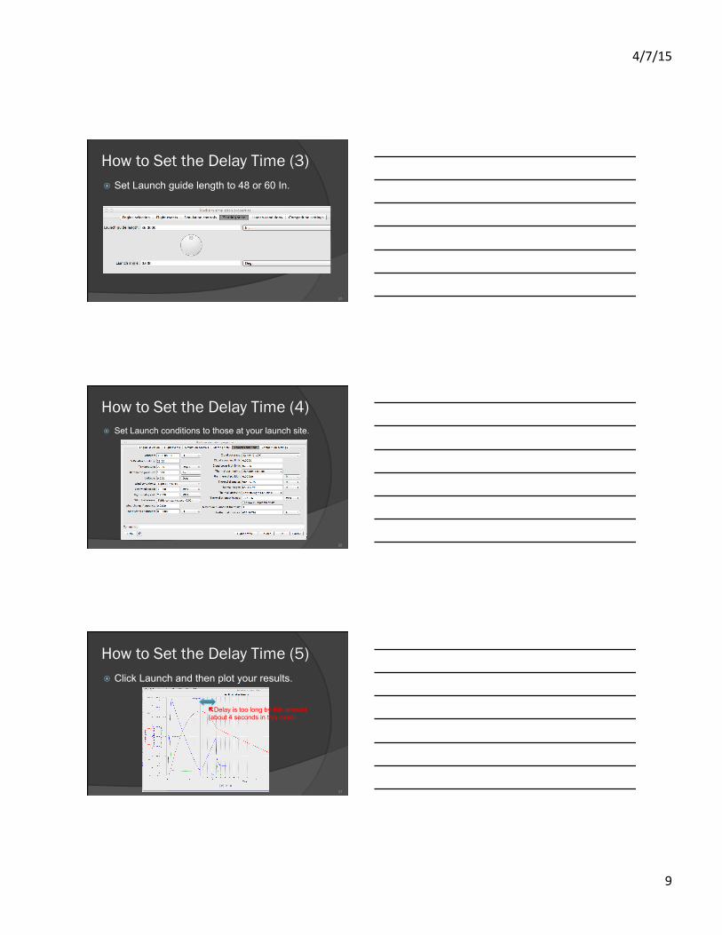
How to Set the Delay Time (3) ! Set Launch guide length to 48 or 60 In.
25
How to Set the Delay Time (4) ! Set Launch conditions to those at your launch site.
26
How to Set the Delay Time (5) ! Click Launch and then plot your results.
!Delay is too long by this amount (about 4 seconds in this case).
27

4/7/15
10
Adjust the Delay, RMS vs. DMS ! The RMS motors use the metal reusable
cases. " Adjust the delay as first step in assembly. " Use the RMS Delay Drilling Tool. " The drilled end faces the propellant grains.
! The DMS are single use motors. " Adjust the delay as first step in assembly. " Use the Universal Delay Drilling Tool.
28
RMS Delay Drilling Tool ! Use the Delay Drilling Tool on your delay grain. ! The drilled end faces the propellant grain(s).
http://www.aerotech-rocketry.com/uploads/76469aad-577b-4972-a6b6-6f955effb89b_Drill%20Tool%201_640.jpg 29
Adjust the Delay DMS (1)
30 http://www.aerotech-rocketry.com/uploads/13a7ea1c-0211-44d4-8954-b76c23bd97ea_DMS%20Instructions%207-9-14%20Small.pdf
Washer

4/7/15
11
Adjust the Delay DMS (2)
31
1.4 Remove the tool and shake out the shavings from the tool and motor bulkhead. Collect the shavings to give to a proctor or professor for proper disposal.
http://www.aerotech-rocketry.com/uploads/13a7ea1c-0211-44d4-8954-b76c23bd97ea_DMS%20Instructions%207-9-14%20Small.pdf
Flight Safety Video II
32
CTI-Style Igniter Installation
Pro 29 Instructions – English – Rev. 1.3 – May 2012 3
Step 3 – Igniter Installation
! Carefully uncoil the igniter leads. Remove any kinks or twists and straighten the wires for about 24” (60 cm) from the
igniter head. Remove the yellow nozzle cap from the motor and feed the shunted ends of the igniter leads through the inside of the nozzle cap and out through the hole.
! Insert the igniter head into the nozzle and push until it stops against the igniter pellet. With the igniter in this position, bend a loop into the igniter leads one cap length from the nozzle exit (Figure 3 – igniter shown outside motor for indication of approximate location of the igniter pellet).
! Slide the nozzle cap up to the loop made in the previous step and firmly push the yellow nozzle cap over the nozzle and loop previously made to retain the igniter (Figure 4).
! Remove the shunt and separate the wire leads ONLY while the rocket is installed on the pad and the launch control system is rendered safe (i.e. disarmed and shunted where applicable).
Important notes: ! Only use the igniter provided with the reload kit. Do not interchange with other Pro29 igniters or with any other type
of igniter. ! The following motors do not use an igniter pellet, but use a fortified (dipped) igniter instead: 282H399 and 348I204.
WARNING Twist the bare igniter leads together several times BEFORE proceeding with igniter installation. NEVER check continuity of an electric igniter after it has been installed in a rocket motor unless done remotely from launch control while all personnel are in the safe location for rocket launch.
WARNING Never store rocket motors with igniters installed. Do not install igniters until the rocket motor is installed in the rocket vehicle and the rocket vehicle is completely prepared and ready for launch. If weather, safety or other conditions result in a delay of the launch, disconnect all igniters from the launch system and replace the shunts. If the launch is aborted for any reasons, remove the igniters from the motors and install the shunts.
NFPA 1127 – Code for High Power Rocketry, 1995 edition, states the following:
“2-12.4 A person shall install an ignition device in a high-power rocket motor at the launcher or within the area designated by the safety monitor. The rocket shall be pointed in a safe direction during and after installation of the
ignition device.”
This rule must be followed when removing or installing igniters for ANY reason.
Igniter specifications*:
Bridge wire resistance: 0.8 – 1.2 Ω Recommended nominal firing current: 1.25 A
Maximum no-fire current: 0.4A Maximum test current: 0.04A
(*) These are manufacturer’s specs. CTI assumes no responsibility for their use or misinterpretation.
Fig. 3: Igniter installation Fig. 4: Igniter installed
Maximum gap of 1/16” Allowed
33

4/7/15
12
Aerotech-Style Igniter Installation (Deprecated)
34
Aerotech 29 mm O-Ring Locations
35
Securing your microSD card (v3)
1. Attach electrical tape on the underside of your data logger.
2. Insert the microSD card part way. 3. Wrap the tape around the card to fully
insert it. 4. Secure the tape on top of the card
holder.
36

4/7/15
13
1 2
4 37
Questions for you ! How many teams want a stand-alone
altimeter? ! How many potential Level 1 Certs do we
have?
38
Your Questions? ! Data Logger? ! PC Board layout? ! $50 Budget? ! Calibration?
39