three-phase five-level flying capacitor multilevel ...7)i4/version-1/e0704013039.pdf · three-phase...
TRANSCRIPT

International Journal of Engineering Science Invention (IJESI)
ISSN (Online): 2319 – 6734, ISSN (Print): 2319 – 6726
www.ijesi.org ||Volume 7 Issue 4 Ver. I || April 2018 || PP 30-39
www.ijesi.org 30 | Page
Three-Phase Five-Level Flying Capacitor Multilevel inverter For
Harvesting Solar Power
Ada Olokpo1, Goshwe Nentawe
2, David O. Agbo
3
123department Of Electrical/Electronic Engineering, Federal University Of Agriculture,
P.M.B. 2373, Makurdi, Benue State, Nigeria
Corresponding auther : Ada Olokpo
Abstract:Nigeria And Other Developing Countries Have Been Experiencing An Increase In Power Reduction
And Failure Due To Increment Of Population, Depending On National Grid Which Is Not Reliable. This Project
Attempts To Solve The Problem Of Power Energy Using Clean Renewable Power Energy By Designing A Three-
Phase Five-Level Flying Capacitor Multi-Level Inverter (Fcmli) Getting Its Energy From The Sun. The System
Described Was Design And Analyzed In Four Stages; The Solar Energy Harvesting, The Current/Voltage
Control, The Boost Converter And The Fcmli. The Solar Energy Harvesting Described Uses Arrays Of Solar
Panels In Series And Parallel To Obtain The Required Voltage And Current Of (200-240vdc And 12-17a). The
Solar Panels Array Is Connected To A Current/Voltage Controller System That Measures The Current And
Voltage Of The Solar Pv And Generates An Equivalent Scaled Voltage Values For The Current Range 12-17a.
The Voltage Is Scaled Between The Ranges Of 3.8v To 5v For Switching To Occur. The Boost Converter Step Up
The 200-240vdc From The Solar Pv To 415vdc, Only When The Current Of The Pv Is Between 12-17a The
Voltage Step Up Occurs. The 415vdc From The Boost Converter Is Fed Into The Three-Phase Five-Level Fcmli
To Convert It To 415vac Using Pod Modulation Technique. The Simulation Is Done Using Simulink And The
Results From The Simulations Shows That The Fcmli Generates Modified Sinewave After Filtering Using Third
Order Lcl Filter A Sinewave Is Produced. The Thd When Voltage Is Not Filtered Is 22.56% And When The
Voltage Of The Fcmli Is Filtered Is 16.76%; This Shows The Filtered Circuit Generates A Pure Sinewave And
Less Thd, This Design Can Be Connected To Any Grid Via Transformer.
Keywords:Three-Phase Five-Level Flying Capacitor Multilevel Inverter (Fcmli), Pod, Solar Pv,
Current/Voltage Controller, Lcl Filter And Boost Converter.
----------------------------------------------------------------------------------------------------------------------------- ----------
Date of Submission: 24-03-2018 Date of acceptance: 09-04-2018
------------------------------------------------------------------------------------------------------------ ---------------------------
I. Introduction There Has Been A Steady Increase In The Demand For Electricity Because Of Increase In Energy
Demand Due To Increase In Population, Economy Growth And The Rapid Depletion Of Fossil Fuel Sources
Based On Energy Reserve And Rapid Growth Of Energy Demand. The Research For An Alternative Source Of
Power Generation Has Resulted In Renewable Energy As Source Of Energy Which Possibly Has No Harm On
The Environment (Chauhan Et Al., 2013) And Is Abundant Especially Tropic Region Of The World. In 2000,
Ieee Defines An Inverter As A Device That Converts Electrical Power From A Dc Voltage (Dc-Source) Into A
Symmetric Ac Voltage Output Of Desired Magnitude And Frequency Using Electronic Circuits. Numerous
Industrial Applications Have Begun To Require Higher Power Apparatus In Recent Years. Some Medium
Voltage Motor Drives And Utility Applications Require Medium Voltage And Megawatt Power Level. For
Medium Voltage Grid, It Is Troublesome To Connect Only One Power Semiconductor Switch Directly. As A
Result A Multilevel Power Inverter Structure Has Been Introduced As An Alternative In High Power And
Medium Voltage Situations. A Multilevel Inverter Not Only Achieves Higher Power Ratings, But Also Enables
The Use Of Renewable Energy Sources, Such As Photovoltaic, Wind And Fuel Cells Can Easily Interfaced To A
Multilevel Inverters System For Higher Applications In Rodrguez Et Al. (2002). Many Researches Have Been
Done On Solar Energy For Grid Connection, They Are:
Adil & Mohammad (2011) Designed A Multilevel Line Commutated Inverter Topology Which
Improves The Wave Shape And Hence Reduces The Total Harmonic Distortion (Thd) Of The Line Current In A
Grid Tie Line Commutated Inverter.
Anand & Ashok (2012) Designed A Multilevel Using Two Reference Signals Identical To Each Other
With An Offset Equivalent To The Amplitude Of The Triangular Carrier Signal To Generate Pwm Signals For
The Switches. A Digital Pid Current Control Algorithm Was Implemented Using Dsp Tms320f2812 To Keep
The Current Injected Into The Grid Sinusoidal And To Have High Dynamic Performance With Rapidly
Changing Atmospheric Conditions. The Inverter Offers Much Less Total Harmonic Distortion And Can Operate

Three-Phase Five-Level Flying Capacitor Multilevelinverter For Harvesting Solar Power
www.ijesi.org 31 | Page
At Near-Unity Power Factor.
Zameer & Singh (2013) Modelled A Pv Systems Consists Of Solar Pv Array, Power Electronics
Inverter/Converter Based On Matlab And Simulink. They Present A Control Algorithm Of A Three-Phase And
Single Phase Grid-Connected Pv System Which Include The Pv Array And The Electronic Power Conditioning
System, Based On The Matlab/Simulink Software.
Patel (2014)Presents A Simple Basic Theoretical Studies Of Solar Cell And Its Modeling Techniques
Using Equivalent Electric Circuits. He Designed A Solar Pv Power Generation System By Developing The
Subsystems That Make Up The System; Solar Panel, Dc-Dc Converter, Mppt Circuit, Battery Charge Controller
And Load,
Jaysing & Vadirajachary (2014) Proposed A Design On The Performance Evaluation Of Five Level
Inverter For Solar Grid Connected System, Where The Output Current Of The Inverter Can Be Adjusted
According To The Voltage Of The Pv Array.
Suganya & Dellibabu (2015) Worked On A Multilevel Medium-Voltage Inverter For Grid Connected
Pv System Of Medium (0.1–5 Mw) And Large (>5 Mw) Scale Pv Power System.Where Medium Voltage Grid
Connection (Typically 6–36kv) Is Essential For Efficient Power Transmission And Distribution. They Use
Power Frequency Transformer Operating At 50 Or 60hz To Step Up The Inverter’s Low Output Voltage
(Usually = 400v) To The Medium-Voltage Level With Reduce The Thd.
In 2015, Simulation And Analysis Of Multilevel Grid Connected Inverter For Solar Pv System With
Maximum Power Point Tracking (Mppt) Was Proposed By Pramod (2015). Where Mppt Technique Is Used To
Track The Maximum Power From Solar Panel, Because In Photovoltaic Power System Mppt Algorithm Increase
The Efficiency Of The Solar Panel Andmultilevel Inverter Offer Better Performances Results As Compared To
Line Commutated Inverter. The Simulation Result Is Based On Matlab/Simulink Environment.
An Investigation Study Of Total Harmonic Distortion In A Flying Capacitor Multilevel Inverter
With/Without Closed–Loop Feedback Schemes Was Proposed By Shanmuga Et Al. (2013). They Used A Seven
Level To Overcome The Main Drawbacks Of These Inverters Which Are High Harmonic Content And Used
Only For Limited Power Applications. In Order To Overcome This, A Novel Approach Called Closed-Loop
Fcmli Was Proposed, Which Significantly Increases The Level Number Of The Output Waveform And Thereby
Dramatically Reduces The Low-Order Harmonics And Thd. The Proposed System Consists Of A Dc–Dc Power
Converter And A Dc–Ac Multilevel Inverter. In Order To Achieve Low Cost, Easy Control, High Efficiency And
High Reliability, A Capacitor Clamped Dc–Dc Boost Converter Using Minimal Devices Was Introduced To
Interface The Low Voltage Photovoltaic (Pv) Module.
II. Materials And Methods Figure 1 Shows The Block Diagram Of The Three-Phase Controlled Load Using Five-Level Flying
Capacitor Multilevel Inverter Which Consists Of Subsections That Made Up The Whole System. The Array Of
Solar Pvs Are Arranged In Series And Parallel To Generate The Required Current And Voltage. The Solar Pv
Array Is Connected To A Current/Voltage Controller That Keeps The Current And Voltage Within A Rated
Current Range, So That Outside This Rated Current And Voltage There Will Be No Output From The
Current/Voltage Controller To Switch The Mosfet Of Boost Converter. The Boost Converter Duty Circle Is
Controlled By The Rated Current And Voltage Of The Solar Pv And Boost Converter Is Turned To Give A
Constant Output Through The Pi. The Step Up Voltage From The Boost Converter Is Fed Into The Three-Phase
Five-Level Fc Mli Using Pod Switching Pattern,An Ac Voltage Output Is Generated From The Three-Phase
Five-Level Fc Mli Which Is Connected To Three Phase Load (Grid) Via Filter And Transformer.
2.1 Pv Sizing Determine Power Consumption Demands
The First Step In Designing The Array Of The Solar Pv System Is To Find Out The Total Power And
Energy Consumption Of All Loads That Needed To Be Connected To The Solar Pv System. In This Paper The
Solar Pv Panel Is Expected To Power A Load Of 240v, 15a. Since We Are Using 100w, 12vdc Solar Pv Panel To
Generate The Voltage Range Of 200v To 240v And Current Of 12a To 15a, We Calculate The Current Using
Three-Phase Five-Level Flying Capacitor Multilevelinverter For Harvesting Solar Power
www.ijesi.org 32 | Page
Equation (1).
P = Vi (1)
Current = 100/12 = 8.8a
240v = Connecting Ten (20) Pvs In Series Gives
16.6a = Connecting This Ten (2) Pvs In Parallel Gives
2.2 Boost Converters
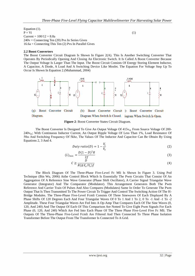
The Boost Converter Circuit Diagram Is Shown In Figure 2(A). This Is Another Switching Converter That
Operates By Periodically Opening And Closing An Electronic Switch. It Is Called A Boost Converter Because
The Output Voltage Is Larger Than The Input. The Boost Circuit Consists Of Energy Storing Element Inductor,
A Capacitor, A Diode, A Load And A Switching Device Like Mosfet. The Equation For Voltage Step Up To
Occur Is Shown In Equation 2.(Muhammad, 2004)
Figure 2: Boost Converter States Circuit Diagram.
The Boost Converter Is Designed To Give An Output Voltage Of 415vdc From Source Voltage Of 200-
240vdc; With Continuous Inductor Current, An Output Ripple Voltage Of Less Than 1%, Load Resistance Of
50ω And Switching Frequency Of 5khz, The Values Of The Inductor And Capacitor Can Be Obtain By Using
Equations 2, 3 And 4.
𝐷𝑢𝑡𝑦 𝑟𝑎𝑡𝑖𝑜 𝐷 = 1 −𝑉𝑠𝑉𝑜
(2)
(𝐿)𝑚𝑖𝑛 =𝐷(1 − 𝐷)2𝑅
2𝑓 (3)
𝐶 ≥𝐷
𝑅 ∆𝑉𝑜 𝑉𝑜 𝑓 (4)
The Block Diagram Of The Three-Phase Five-Level Fc Mli Is Shown In Figure 3. Using Pod
Technique (Bin Wu, 2006) Atthe Control Block Which Is Essentially The Pwm Circuits That Consist Of An
Aggregation Of A Reference Sine Wave Generator (Phase Shift Oscillator), A Carrier Signal Triangular Wave
Generator (Integrator) And The Comparator (Modulator). This Arrangement Generates Both The Pwm
Reference And Carrier Train Of Pulses And Also Compares (Modulates) Same In Order To Generate The Pwm
Output That Is Then Transmitted To The Power Circuit To Trigger And Control The Switching Action Of The H-
Bridge Modules. The Three-Phase Five-Level Fcmli Consists Of Three Sinewaves Of Each Displayed By A
Phase Shifts Of 120 Degrees Each And Four Triangular Waves Of 0 To 1 And 1 To 2, 0 To -1 And -1 To -2
Amplitude. These Four Triangular Waves Are Fed Into A Op-Amp That Compares Each Of The Sine Waves (0,
120, And 240) And The Output Of Each Of This Comparison Are Notted To Give Eight Pwm Signals For Each
Phase (0, 120, And 240) Which Are Fed Into Each Phase Of The Three Phase Five-Level Five Fc Mli. The
Outputs Of The Three-Phase Five-Level Fcmli Are Filtered And Then Connected To Three Phase Isolation
Transformer Before The Output From The Transformer Is Connected To A Grid.

Three-Phase Five-Level Flying Capacitor Multilevelinverter For Harvesting Solar Power
www.ijesi.org 33 | Page
Figure 3: Block Diagram Of The Five Level Three Phase Fc Mli
The Circuit In Figure 4 Shows A Single Phase Five-Level Fcmli Which Uses Eight Power
Semiconductor Switches, Three Flying Capacitors And Two Dc Link Capacitors. This Fcmli Consists Of Four
Switching Pairs (S1 S8), (S2 S7), (S3 S6) And (S4 S5). If One Switch Of The Pair Is Switched On, The Other
Complementary Switch Of Same Pair Must Be Off. The Switches Are Clamped By Dc-Link Together With
Flying Capacitors. The Four Switches (S1-S4) Must Be Connected In Series Between Dc Input And Load And
Likewise For (S5-S8). The Three Flying Capacitors C3, C4 And C5 Are Charged To Different Voltage Levels.
By Changing The Transistor Switching States, The Capacitors And The Dc Source Are Connected In Different
Ways To Produce Various Load Voltages. Typical Switch Combinations To Obtain The Required Output
Voltage Levels For Five-Level Fcmli Are Shown In Table 1.In The Circuit Configuration Of The Three-Phase
Five-Level Fc Mli, The Inverter Is Powered By A Single Dc Source. The Dc Source Is Obtained From The
Output Of The Boost Converter.
Figure 4: Basic Circuit Of A Single-Phase Five-Level Fc Mli.
Table 1: Switching States/Patterns Of A Five-Level Fc Mli (Positive Load Current)
Outpu
t
Voltage
Level
Switching States
S1 S2 S3 S4 S5 S6 S7 S8
Vdc/2 1 1 1 1 0 0 0 0
Vdc/4 0 1 1 1 0 0 0 1
Vdc/4 1 0 1 1 0 0 1 0
Three-Phase Five-Level Flying Capacitor Multilevelinverter For Harvesting Solar Power
www.ijesi.org 34 | Page
Vdc/4 1 1 0 1 0 1 0 0
Vdc/4 1 1 1 0 1 0 0 0
0 1 0 0 1 0 1 1 0
0 0 1 0 1 0 1 0 1
0 1 0 1 0 1 0 1 0
0 0 0 1 1 0 0 1 1
0 0 1 1 0 1 0 0 1
0 1 1 0 0 1 1 0 0
-Vdc/4 0 0 0 1 0 1 1 1
-Vdc/4 0 0 1 0 1 0 1 1
-Vdc/4 0 1 0 0 1 1 0 1
-Vdc/4 1 0 0 0 1 1 1 0
-Vdc/2 0 0 0 0 1 1 1 1
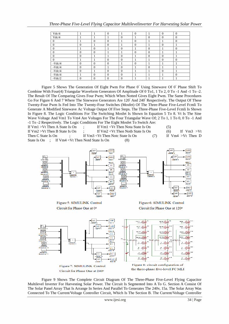
Figure 5 Shows The Generation Of Eight Pwm For Phase 0ᵒ Using Sinewave Of 0
ᵒ Phase Shift To
Combine With Four(4) Triangular Waveform Generators Of Amplitude Of 0 To1, 1 To 2, 0 To -1 And -1 To -2.
The Result Of The Comparing Gives Four Pwm; Which When Notted Gives Eight Pwm. The Same Procedures
Go For Figure 6 And 7 Where The Sinewave Generators Are 120ᵒ And 240
ᵒ Respectively. The Output Of These
Twenty-Four Pwm Is Fed Into The Twenty-Four Switches (Mosfet) Of The Three-Phase Five-Level Fcmli To
Generate A Modified Sinewave Ac Voltage Output Of Five Steps. The Three-Phase Five-Level Fcmli Is Shown
In Figure 8. The Logic Conditions For The Switching Mosfet Is Shown In Equation 5 To 8. Vt Is The Sine
Wave Voltage And Vm1 To Vm4 Are Voltages For The Four Triangular Wave Of; 2 To 1, 1 To 0, 0 To -1 And
-1 To -2 Respectively. The Logic Conditions For The Eight Mosfet To Switch Are:
If Vm1 >Vt Then A State Is On ; If Vm1 <Vt Then Nota State Is On (5)
If Vm2 >Vt Then B State Is On ; If Vm2 <Vt Then Notb State Is On (6) If Vm3 >Vt
Then C State Is On ; If Vm3 <Vt Then Notc State Is On (7) If Vm4 >Vt Then D
State Is On ; If Vm4 <Vt Then Notd State Is On (8)
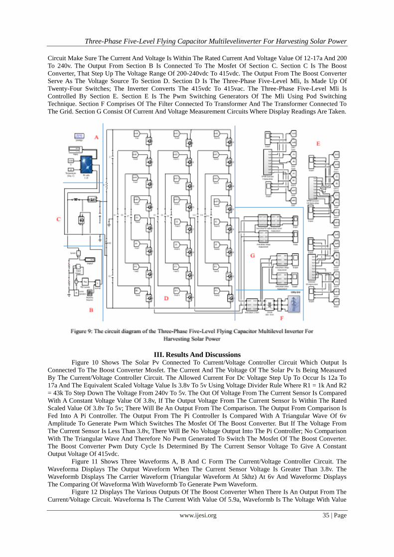
Figure 9 Shows The Complete Circuit Diagram Of The Three-Phase Five-Level Flying Capacitor
Multilevel Inverter For Harvesting Solar Power. The Circuit Is Segmented Into A To G. Section A Consist Of
The Solar Panel Array That Is Arrange In Series And Parallel To Generates The 240v, 15a. The Solar Array Was
Connected To The Current/Voltage Controller Circuit, Which Is The Section B. The Current/Voltage Controller
Three-Phase Five-Level Flying Capacitor Multilevelinverter For Harvesting Solar Power
www.ijesi.org 35 | Page
Circuit Make Sure The Current And Voltage Is Within The Rated Current And Voltage Value Of 12-17a And 200
To 240v. The Output From Section B Is Connected To The Mosfet Of Section C. Section C Is The Boost
Converter, That Step Up The Voltage Range Of 200-240vdc To 415vdc. The Output From The Boost Converter
Serve As The Voltage Source To Section D. Section D Is The Three-Phase Five-Level Mli, Is Made Up Of
Twenty-Four Switches; The Inverter Converts The 415vdc To 415vac. The Three-Phase Five-Level Mli Is
Controlled By Section E. Section E Is The Pwm Switching Generators Of The Mli Using Pod Switching
Technique. Section F Comprises Of The Filter Connected To Transformer And The Transformer Connected To
The Grid. Section G Consist Of Current And Voltage Measurement Circuits Where Display Readings Are Taken.
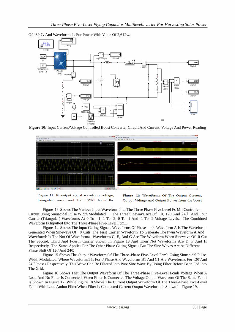
III. Results And Discussions Figure 10 Shows The Solar Pv Connected To Current/Voltage Controller Circuit Which Output Is
Connected To The Boost Converter Mosfet. The Current And The Voltage Of The Solar Pv Is Being Measured
By The Current/Voltage Controller Circuit. The Allowed Current For Dc Voltage Step Up To Occur Is 12a To
17a And The Equivalent Scaled Voltage Value Is 3.8v To 5v Using Voltage Divider Rule Where R1 = 1k And R2
= 43k To Step Down The Voltage From 240v To 5v. The Out Of Voltage From The Current Sensor Is Compared
With A Constant Voltage Value Of 3.8v, If The Output Voltage From The Current Sensor Is Within The Rated
Scaled Value Of 3.8v To 5v; There Will Be An Output From The Comparison. The Output From Comparison Is
Fed Into A Pi Controller. The Output From The Pi Controller Is Compared With A Triangular Wave Of 6v
Amplitude To Generate Pwm Which Switches The Mosfet Of The Boost Converter. But If The Voltage From
The Current Sensor Is Less Than 3.8v, There Will Be No Voltage Output Into The Pi Controller; No Comparison
With The Triangular Wave And Therefore No Pwm Generated To Switch The Mosfet Of The Boost Converter.
The Boost Converter Pwm Duty Cycle Is Determined By The Current Sensor Voltage To Give A Constant
Output Voltage Of 415vdc.
Figure 11 Shows Three Waveforms A, B And C Form The Current/Voltage Controller Circuit. The
Waveforma Displays The Output Waveform When The Current Sensor Voltage Is Greater Than 3.8v. The
Waveformb Displays The Carrier Waveform (Triangular Waveform At 5khz) At 6v And Waveformc Displays
The Comparing Of Waveforma With Waveformb To Generate Pwm Waveform.
Figure 12 Displays The Various Outputs Of The Boost Converter When There Is An Output From The
Current/Voltage Circuit. Waveforma Is The Current With Value Of 5.9a, Waveformb Is The Voltage With Value
Three-Phase Five-Level Flying Capacitor Multilevelinverter For Harvesting Solar Power
www.ijesi.org 36 | Page
Of 439.7v And Waveformc Is For Power With Value Of 2,612w.
Figure 10: Input Current/Voltage Controlled Boost Converter Circuit And Current, Voltage And Power Reading
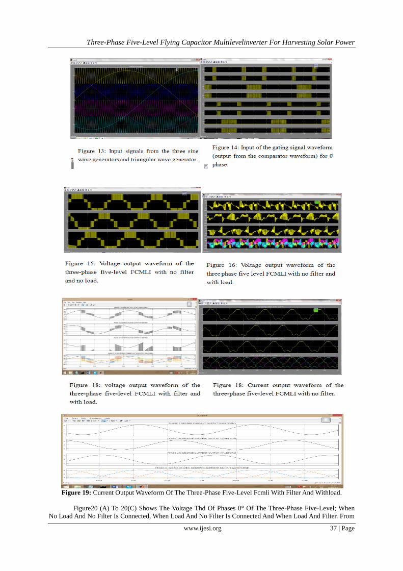
Figure 13 Shows The Various Input Waveform Into The Three Phase Five Level Fc Mli Controller
Circuit Using Sinusoidal Pulse Width Modulated . The Three Sinewave Are Of 0, 120 And 240̊ And Four
Carrier (Triangular) Waveforms At 0 To - 1; 1 To -2; 0 To -1 And -1 To -2 Voltage Levels. The Combined
Waveform Is Inputted Into The Three-Phase Five-Level Fcmli.
Figure 14 Shows The Input Gating Signals Waveforms Of Phase 0̊. Waveform A Is The Waveform
Generated When Sinewave Of 0̊ Cuts The First Carrier Waveform To Generate The Pwm Waveform A And
Waveformb Is The Not Of Waveforma . Waveforms C, E, And G Are The Waveform When Sinewave Of 0̊ Cut
The Second, Third And Fourth Carrier Shown In Figure 13 And Their Not Waveforms Are D, F And H
Respectively. The Same Applies For The Other Phase Gating Signals But The Sine Waves Are At Different
Phase Shift Of 120̊ And 240.̊
Figure 15 Shows The Output Waveform Of The Three -Phase Five-Level Fcmli Using Sinusoidal Pulse
Width Modulated. Where Waveforma1 Is For 0̊ Phase And Waveforms B1 And C1 Are Waveforms For 120̊ And
240̊ Phases Respectively. This Wave Can Be Filtered Into Pure Sine Wave By Using Filter Before Been Fed Into
The Grid.
Figure 16 Shows That The Output Waveform Of The Three-Phase Five-Level Fcmli Voltage When A
Load And No Filter Is Connected, When Filter Is Connected The Voltage Output Waveform Of The Same Fcmli
Is Shown In Figure 17. While Figure 18 Shows The Current Output Waveform Of The Three-Phase Five-Level
Fcmli With Load Andno Filter.When Filter Is Connected Current Output Waveform Is Shown In Figure 19.
Three-Phase Five-Level Flying Capacitor Multilevelinverter For Harvesting Solar Power
www.ijesi.org 37 | Page
Figure 19: Current Output Waveform Of The Three-Phase Five-Level Fcmli With Filter And Withload.
Figure20 (A) To 20(C) Shows The Voltage Thd Of Phases 0° Of The Three-Phase Five-Level; When
No Load And No Filter Is Connected, When Load And No Filter Is Connected And When Load And Filter. From
A1
B2
C1
A
B
C
D
E
F
G
H

Three-Phase Five-Level Flying Capacitor Multilevelinverter For Harvesting Solar Power
www.ijesi.org 38 | Page
The Results It Shows That Filtered Voltage Has Lesser Thd But There Is Voltage Drop Across The Filter.
Figure 20: The Thd Voltage Waveforms Of The Three-Phase Five Level Fcmli
3.1 Discussion
The Output Of The Solar Pv From The Simulation Gives 240vdc, 15a Which Is Feed Into The Current/Voltage
Controller Due To The Effect Of Irradiance On The Output Pv Solar Current. Table 2 Shows The Effect Of
Irradiance On Current And Voltage And From The Table 2 It Shows That Irradiance Has More Effect On Current
Than Voltage That Is Why A Current Controller Was Designed And Turning The Pi, The Boost Converter Can
Step Up The Voltage From 200-240vdc To A Constant 415vdc And This 450vdc Fed The Three-Phase Five-
Level Fcmli And 415vac Is Generated At The Output Voltage Of The Three-Phase Five-Level Fcmli. Table 3
Shows The Thd Of The Output Voltage, From The Table Its Shows That The Filtered Wave Have The Less Thd
Compared To Others.
Table 2: Frequency Modulation Index Variation Table For Voltage Components On No Load Irradiance Values Voltage Values @25 In Series Current Values @25 In Parallel
1000 249.9 17.24
750 245.9 12.93
500 242.0 8.63
250 232.5 4.31
100 210.3 1.73
50 128.7 0.86
10 25.96 0.17
Table 3: Frequency Modulation Index Variation Table For Voltage Components On No Load State Of The Inverter Thd % Voltage Of Each State
Connected Without Load And No Filter 33.97%
Connected With Load And No Filter 101.71%
Connected Without Load With Filter 16.76%

Three-Phase Five-Level Flying Capacitor Multilevelinverter For Harvesting Solar Power
www.ijesi.org 39 | Page
IV. Conclusion Inthis Project The Design Of A Three-Phase Five-Level Flying Capacitor Mli For Harvesting Of Solar
Energy Using Spwm Technique For Optimizes Solar Energy Harvesting. The Three-Phase Five-Level Flying
Capacitor Mli Is A Project Design To Help Increase The Grid Power Using Renewable Power Source. The Use
Of Mlis For The System Is Able To Easily Achieve Pure Sinewave After Filtering Of The Modified Wave That
Comes Out Of The Mli. The Pure Sinewave Can Be Connected To The Grid To Boost The National Grid Since
The Solar Energy Is Free And Readily Available At The Day Time And Where The Usage Of Power Energy Is
At Its Peak. It Can Also Help To Improve The Poor Power Supply In Developing Countries And Rural Areas
And Can Also Be Used As Stand-Alone Power Supply. Simulation Of The System Was Done Using Matlab And
Results Obtained Were Turned To Obtain Less Thd For Voltage Waveform.
References [1] Adil S., And Mohammad S. J. A. (2011).Simulation And Analysis Of A Multilevel Converter Topology For Solar Pv Based Grid
Connected Inverter. Smart Grid And Renewable Energy (Http://Www.Scirp.Org/Journal/Sgre), Vol. 2, Pp 56-62. [2] Akira Nabae, Isao Takahashi, Hirofumi Akagi (1981). “A New Neutral-Point Clamped Pwm Inverter ". Ieee Transaction On
Industry Applications, Vol. Ia-17, No. 5.
[3] Anand R. And Ashok Kumar G. (2012). A Multilevel Inverter For Gridconnected Photovoltaic System ByEmploying Pid Controller.Internationaljournal Of Engineering And Advanced Technology Vol. 2,Issue 1.
[4] Jaysing Ȧ. A. K. Ȧ., And Vadirajachary K. (2014). A Performance Evaluation Of Five Level Inverter For Solar Grid Connected
System. International Journal Of Current Engineering And Technolog, Special Issue-3. [5] Chauhan D., Agarwal S., And Suman M.K, (2013). "Policies For Development Of Photovoltaic Technology: A Review".
International Journal Of Software & Hardware Research In Engineering, Vol. 1, Pp.52-57.
[6] Muhammad H. Rashid (2004).Power Electronics: Circuits, Devices And Applications" Text Book, Third Edition, Prentice Hall. [7] Patel Rupesh (2014). Design And Implementation Of An Isolated Solar Photovoltaic Power Generation System. National Institute
Of Technology, Department Of Electrical Engineering. Rourkela, Odisha.
[8] Pramod R. N. (2015). Simulation And Analysis Of Multilevel Grid Connected Inverter For Solar Pv System With Maximum Power Point Tracking International Journal Of Scientific Engineering And Applied Science, Vol. 1, Issue 3.
[9] Rodrguez J., Jih-Sheng Lai, And Fang Zheng Peng (2002) “Multilevel Inverters: A Survey Of Topologies, Controls, And
Applications ", Ieee Transactions On Industrial Electronics, Vol. 49, No. 4. [10] Shanmuga P. S., Ramani. K, And Rangasamy K. S. (2013). An Investigation Study Of Total Harmonic Distortion In A Flying
Capacitor Multilevel Inverter With Or Without Closed–Loop Feedback Schemes. Global Journal Of Inc., Vol. 13, Issue 3.
[11] Suganya K., And Dellibabu S. (2015). A Multilevel Medium-Voltage Inverter For Grid Connected Photovoltaic System. International Journal Of Advanced Research Trends In Engineering And Technology Vol. Ii, Special Issue I.
[12] Zameer A., And Singh S.N. (2013). Modeling And Control Of Grid Connected Photovoltaic System. International Journal Of
Emerging Technology And Advanced Engineering, Vol. 3, Issue 3. Www.Powerinverterwikepedia
Ada Olokpo”Three-Phase Five-Level Flying Capacitor Multilevel inverter For Harvesting
Solar Power” International Journal of Engineering Science Invention (IJESI), vol. 07, no.
04, 2018, pp 30-39