three-phase industrial inverter ond4 series - gentec - … · · 2016-12-22three-phase industrial...
TRANSCRIPT

OND4 SERIESOND4 SERIESOND4 SERIESOND4 SERIES
Three-phase Industrial Inverter OND4 SERIES
The new OND4 SERIES inverter provides safe, pure sine wave, single-phase or three-phase reliable power to critical control equipment.
These inverters are of the “online” type. The load is fed by the inverter and uses a static switch to trans-fer to AC emergency supply in the unlikely event of an inverter failure. It can then power critical loads without interruption in case of a loss of electric supply. These true online inverters integrate pulse width modulation (PWM) con-trol combined with high frequency IGBT power transistors. The system includes: - an inverter (DC/AC converter);
- a static switch; - a maintenance bypass switch
(to isolate the system). Typical customers includes utilities and heavy industry.
♦ Designed specially to fulfil the needs of the industries and power company substations
♦ Ideal for powering lighting and process control systems
♦ Mature and proven technology ♦ Easy to maintain ♦ Customer support from a comprehensive
team of engineers and technicians ♦ Life span of more than 25 years ♦ Compatible with non-linear loads ♦ Pure sinusoidal waveform
♦ Single- or three-phase output ♦ Isolated input/output ♦ 125Vdc or 250Vdc input ♦ Output voltage up to 600Vac ♦ Static switch for transfer without
interruption ♦ Redundant system available ♦ Embedded WEB server ♦ DNP3 communication protocol ♦ Secured access
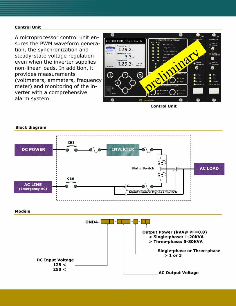
Control Unit
A microprocessor control unit en-sures the PWM waveform genera-tion, the synchronization and steady-state voltage regulation even when the inverter supplies non-linear loads. In addition, it provides measurements (voltmeters, ammeters, frequency meter) and monitoring of the in-verter with a comprehensive alarm system.
Control Unit
ONDULEUR, SÉRIE OND4
Modèle
Output Power (kVA@ PF=0.8) > Single-phase: 1-20KVA > Three-phase: 5-80KVA
Single-phase or Three-phase > 1 or 3
AC Output Voltage
DC Input Voltage 125 <
250 <
- OND4- - -
Block diagram
AC LOAD
DC POWER
CB3
AC LINE (Emergency AC)
INVERTER
Maintenance Bypass Switch
NC
NO
Static Switch
CB6

Configuration The inverters are available according to the following configurations: Standard System: Each system is made up of a single inverter system. Master-Slave Redundant System: Each system is made up of two (2) redundant inverter systems operating as follows: One
(inverter A) is the master and feeds the load. If it fails, the static switch (A) transfers the load to the second unit (inverter B) that then supplies the load. Afterwards, if inverter B fails, the static
switch (B) will transfer the load to the emergency AC supply. Parallel Redundant System: Each system is made up of two (2) redundant inverter systems operating as follows: Normally,
inverters (A) and (B) feed the load that is equally split between both inverters. In the case one inverter fails, the other takes up the load totally. If both inverters fail, the static switches trans-
fer the load to the emergency AC power.
Redundant Configuration (master-slave)
LOAD
STATIC
SWITCH A
INVERTER A
STATIC
SWITCH B
INVERTER B
Emergency Vac
Vdc
Vdc
Redundant Configuration (parallel)
LOAD
STATIC
SWITCH A
INVERTER A
STATIC
SWITCH B
INVERTER B
Emergency Vac
Vdc
Vdc
Emergency Vac

The alarms and indications use LEDs and are described on the LCD display of the control unit. The alarms are associated with alarm contacts. Also, they may be transmitted remotely by the
communication ports.
The alarm settings are easily adjustable remotely through the communication ports, or in the field with a laptop computer connected to the WEB server of the control unit.
- inverter failure; - low/high Vdc voltage; - low/high Vac voltage; - static switch failure; - load on bypass supply;
- bypass supply absent; - inverter out of synchronism
with the bypass supply;
- maintenance bypass switch
in “bypass” position.
Alarms and indicators
DATA COMMUNICATION Recover data, built system performance history The system supports communication through DNP3 Protocol (level 2). You may establish a connection
through any of the two (2) Ethernet ports (both optical and copper) available on the system. With this connection, it is possible to transmit all measurements, alarms and indicators to a processing or control center. You may also remotely control the system through this connection. By saving the data history
transmitted, the processing center will be able to analyze the system long-term performance.
WEB ACCESS TO INFORMATION Make your job easier by accessing the charger’s WEB server!
WEB page «Dashboard»
Using any commercial WEB browser, the system provides various information pages, such as:
• A dashboard presenting the real-time system status.
• The actual operating parameters set for the system.
• The current readings for measure-ments, alarms and indicators.
• Recovery mechanisms for data histo-ry saved by the system.
• Maintenance information allowing parameters and software update.

Characteristics DC INPUT
Nominal input voltage 125Vdc or 250Vdc (range 105-140Vdc or 210-280Vdc)
Protection thermal magnetic circuit breaker, 2 poles
AC INPUT (emergency AC)
Protection thermal magnetic circuit breaker, 1 or 3 poles
AC OUTPUT
Voltage 120/208/220/240/277Vac – single-phase (L,N) (note: for 240V, the third wire (L2) is not available, an additional transformer is required after the output) 208/380/480/600Vac – three-phase «Y» (L1, L2, L3, N)
Fréquence 60Hz (50Hz optional)
Power (at P.F. = 0.8) 1kVA to 20kVA single-phase / 5kVA to 80kVA three-phase
Power factor 0.7 to 1.0 inductive load
Crest Factor 3.0 (pick current value / nominal RMS current)
Voltage regulation (100% load variation)
• static (balanced load): ± 0.5%
• static (100% unbalanced load): ± 2.0%
• dynamic: ± 5%, returns at ± 1% within less than 3 cycles (50ms)
Frequency regulation ± 0.1%
Overload 125% for 10 min. / 150% for 60 sec.
Efficiency (full load) ≥90%
Harmonic distosion (THD) Linear load: 3.0% max./ 100% non-linear load: 5.0% max.
Cooling Natural convection up to 3KVA / forced over 3KVA Note: Always forced on NEMA12 cabinets
STATIC SWITCH
Transfer time “without interruption” 4.0ms max. (1/4 cycle)
Protection Semiconductor fuses
Maintenance bypass switch included
Measuring Apparatus / Communication Ports LCD display, 95mm x 54mm, 480 x 272, with secured access (3 levels)
- DC voltmeter, range: 0-120%, accuracy: 0.1% - DC ammeter, range: 0-150%, accuracy: 1.0% - AC voltmeter, range: 0-120%, accuracy: 0.2% - AC ammeter, range: 0-150%, accuracy: 1.0% - frequency meter, range: 50 to 70 hz, accuracy: 0.5% - active power (W) / apparent power (VA), range: 0-150%, accuracy: 1.0% - synoptic and various information/measurements
♦ 2 Ethernet ports (both optical and copper) (DNP3, HTTPS):
- copper 10/100/1000Mbps on RJ-45 plug (10/100/1000BASE-X) - optical 100Mbps on duplex LC plug (100BASE-FX)
♦ or Ethernet RJ45 plug (protocol Modbus/TCP slave)
Environmental Specifications Operating temperature -10 oC—40 oC (14oF—104oF)
Storage temperature -20 oC—70 oC (-4oF—158oF)
Relative humidity 5—95% at 40 oC (104oF) without condensing
Audible noise 65 dBA max. measured at 1.0 meter (3 feet)
Altitude derating 0% @ 0-1000 meters (3,280 feet)
Testing Performance and tests CEI 62040-3
Dielectric test CEI 62040-1
Surge Withstand Capability (SWC) ANSI/IEEE C37.90.1/CEI 60255-22-1/-4
Electrostatic discharge (ESD) CEI 61000-4-2
Electromagnetic compatibility(EMC) CEI 62040-2
Fire resistance UL94 V-0 and V-1
Environmental CEI 60068-2-1/-2/-3
Standards Meets CSA-C22.2 no 107.3, UL1778

120-4
6550
Printe
d in C
anada—
11/2
016
Cabinets Dimensions (H x L x D) cabinet A1: 1800x600x600mm (70.9 x 23.6 x 23.6 in.),
freestanding, NEMA1 cabinet A2: 2000x800x800mm (78.7 x 31.5 x 31.5 in.), freestanding, NEMA1 (depth : additional clearance of 100 or 144 mm is required behind for ventilation)
Material Cold laminated steel 2.0/3.0 mm
Cabinet Type NEMA1/IP20 (or NEMA12/IP52)
Colour Gray ANSI61 (Other colours on demand)
Cabinet A1, power ≤7.5KVA (note: natural convection up to ≤3KVA)
Cabinet A2, power >7.5KVA