three-phase programmable resettable sectionalizer (3Ø prs) · three-phase programmable resettable...
TRANSCRIPT

June 2015
Phone: 573-682-5521 Email: [email protected] Web: hubbellpowersystems.com
Page 10DDDD-1
Catalog 10DDDD June 2015
Three-PhaseProgrammable Resettable Sectionalizer
(3Ø PRS)
10DDDD
June 2015Page 10DDDD-2
Phone: 573-682-5521 Email: [email protected] Web: hubbellpowersystems.com
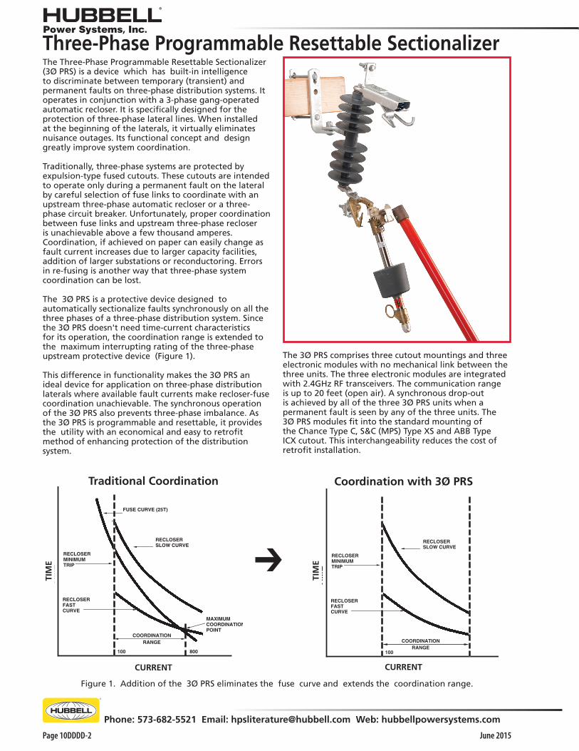
Three-Phase Programmable Resettable SectionalizerThe Three-Phase Programmable Resettable Sectionalizer (3Ø PRS) is a device which has built-in intelligence to discriminate between temporary (transient) and permanent faults on three-phase distribution systems. It operates in conjunction with a 3-phase gang-operated automatic recloser. It is specifically designed for the protection of three-phase lateral lines. When installed at the beginning of the laterals, it virtually eliminates nuisance outages. Its functional concept and design greatly improve system coordination.
Traditionally, three-phase systems are protected by expulsion-type fused cutouts. These cutouts are intended to operate only during a permanent fault on the lateral by careful selection of fuse links to coordinate with an upstream three-phase automatic recloser or a three-phase circuit breaker. Unfortunately, proper coordination between fuse links and upstream three-phase recloser is unachievable above a few thousand amperes. Coordination, if achieved on paper can easily change as fault current increases due to larger capacity facilities, addition of larger substations or reconductoring. Errors in re-fusing is another way that three-phase system coordination can be lost.
The 3Ø PRS is a protective device designed to automatically sectionalize faults synchronously on all the three phases of a three-phase distribution system. Since the 3Ø PRS doesn't need time-current characteristics for its operation, the coordination range is extended to the maximum interrupting rating of the three-phase upstream protective device (Figure 1). This difference in functionality makes the 3Ø PRS an ideal device for application on three-phase distribution laterals where available fault currents make recloser-fuse coordination unachievable. The synchronous operation of the 3Ø PRS also prevents three-phase imbalance. As the 3Ø PRS is programmable and resettable, it provides the utility with an economical and easy to retrofit method of enhancing protection of the distribution system.
Figure 1. Addition of the 3Ø PRS eliminates the fuse curve and extends the coordination range.
FUSE CURVE (25T)
RECLOSERMINIMUMTRIP
RECLOSERFASTCURVE
COORDINATIONRANGE
TIM
E
CURRENT
100 800
MAXIMUMCOORDINATIONPOINT
RECLOSERSLOW CURVE
CURRENT
Traditional Coordination
TIM
E ➔
TIM
E
RECLOSERMINIMUMTRIP
RECLOSERFASTCURVE
TIM
E
CURRENT
100
RECLOSERSLOW CURVE
COORDINATIONRANGE
Coordination with 3Ø PRS
CURRENT
The 3Ø PRS comprises three cutout mountings and three electronic modules with no mechanical link between the three units. The three electronic modules are integrated with 2.4GHz RF transceivers. The communication range is up to 20 feet (open air). A synchronous drop-out is achieved by all of the three 3Ø PRS units when a permanent fault is seen by any of the three units. The 3Ø PRS modules fit into the standard mounting of the Chance Type C, S&C (MPS) Type XS and ABB Type ICX cutout. This interchangeability reduces the cost of retrofit installation.

June 2015
Phone: 573-682-5521 Email: [email protected] Web: hubbellpowersystems.com
Page 10DDDD-3
Operation
The three modules of the 3Ø PRS are programmed to maintain a constant radio link when all the units are powered by the line current through the built in current transformer on each unit.
Each unit can detect fault current when the line current exceeds the programmed actuating current. The unit will sense the subsequent open circuit ("dead-line") condition caused by the upstream recloser acting on the fault current. This event is registered as a "count".
If the fault is temporary and cleared before the "count" reaches the programmed "count", the unit does not operate and after the reset time expires, the "count" is reset. If the fault is permanent, the unit will see multiple instances of fault current followed by recloser opening and in each instance, the "count" will be incremented.
After detecting the programmed number of "counts", the unit (detecting the fault) will use the radio link to command the other two units in the set to drop open. The radio signal communication and acknowledgement process is completed within 30 msec and upon receiving a positive acknowledgement from all units in the set, all 3 units will drop open within 20 msec of each other. Thus, all 3 phases of the faulted section will be isolated synchronously while the upstream recloser is in the open position, maintaining 3-phase system balance.
Trunnion Design
The Three-Phase PRS is equipped with a patent pending trunnion design which enables the sectionalizers to be reset while still in the cutout mounting base. If removal from the cutout mounting base is necessary, the sectionalizers can be manually reset using a wrench.
Drop-open operation is the same for both types of the 3Ø PRS: Stan-dard (left) and Loadbreak (right, with Arc Chute interrupter). See following pages for specifications and ordering information.
Application
The 3Ø PRS is best suited for use in the following applications:
• Locations where fuse coordination is difficult to achieve
• Areas with insufficient load to justify investments in apparatus such as reclosers
• Remote locations prone to frequent faults caused by fauna and/or flora
Benefits
• SAIDI improvements
• Distinguishes between permanent and transient faults to reduce outages
• Three programmable units meet all needs per specific voltage class reducing inventory
• Historical data storage, report generation for system overview and analysis
• Ability to record and track total number of the blinks on the line from the date of installation.
• Resettable in the cutout mounting base , no consumable parts
For Specifications, see following pages.
Push towards cutout to reset

June 2015Page 10DDDD-4
Phone: 573-682-5521 Email: [email protected] Web: hubbellpowersystems.com
System Voltage:The sectionalizer must have a voltage rating equal to or greater than the system voltage.
Continuous Current:The sectionalizer must have a continuous current rating equal to or greater than the anticipated system load current plus overload.
Where hydraulic reclosers are used, the continuous current rating of the sectionalizer is typically equal to the continuous current rating of the upstream automatic circuit recloser.
Minimum Actuating Current:The minimum actuating current of sectionalizers should be 80% of the phase minimum trip of the source side single-phase automatic circuit recloser (ACR). Where three-phase reclosers or circuit breakers are used, a user may want to coordinate the sectionalizer's actuating current with the ground trip rating.
Where hydraulic reclosers are used, this is easily accomplished by matching the sectionalizer and the recloser’s continuous current ratings. The sectionalizer’s minimum actuating current is 160% of its continuous current rating and the hydraulic reclosers’ phase pick-up is 200% of its continuous current rating (160/200=.80). (Table A).
Deadline Current Threshold:The deadline current threshold is the current the 3Ø PRS unit should see to send a drop open signal to the other two 3Ø PRS units after the unit has reached its programmed number of counts. The device verifies that the current on the line is below the programmed deadline current threshold for 80ms before the synchronous trip signal is sent.
In case of a 2-fast/2-slow reclose setting, a 2-count sectionalizer may be used to reduce the number of recloser operations (Figure 2, line B).
Figure 2. Typical distribution system with Type PRStwo- and three-count electronic resettable sectionalizers.
PRS
PRS
PRS
PRS
PRS
Three-Phase Programmable Resettable Sectionalizer
Table A. Recloser/sectionalizer coordination.
Minimum ActuatingCurrent,
Amps ± 10%
24 40 56 80112160224320
ContinuousCurrent,
Amps
15 25 35 50 70100140200
Recloser
Minimum Trip,Amps
30 50 70100140200280400
Typical Sectionalizer Ratings
Where sectionalizers are used in series, the downstream sectionalizer should have one less count than the upstream sectionalizer (Figure 3).
Figure 3. Coordination of sectionalizersin series.
PRS
PRS
Number of Counts:The sectionalizer should be set to operate in at least one less count than the backup recloser. Example: a 4-shot recloser would require a maximum of a 3-count sectionalizer downstream (Figure 2, line A).

June 2015
Phone: 573-682-5521 Email: [email protected] Web: hubbellpowersystems.com
Page 10DDDD-5
For Catalog Number System, see following pages.
Technical Specifications
* With 5% accuracy, if the unit is programmed for 50 A actuating current, then the unit will pick-up the count at 52.5 A and above but ignore a count at 47.5 A and below.
Note: Ratings are based on testing conducted at 60Hz
Three-Phase Programmable Resettable Sectionalizer
Rated Power Frequency 60 Hz/50 Hz
Rated Voltage (BIL) 15kV (110kV BIL)27kV (125kV BIL)38kV (150/170kV BIL)
Rated Continuous Current 300 Amps
Minimum Line Current 10 Amps
Minimum Actuating Current Programmablebetween 16 A and 480 A
Number of Counts: Programmable for1, 2, 3 or 4 counts
Reset time: Programmable,30 seconds to 300seconds with resolution of 1 second
Inrush detection time Less than 1 cycle
Types of inrush currents detected: Symmetrical andAsymmetrical
Method of inrush currents detection: Fourier Analysis (FFT)
Deadline detection: ≤ 200mA
Total execution time: 130 msec (± 20 msec)
Short time current withstand,15 cycle (at 60 Hz):
1 second:3 seconds:
8600 Amps Sym.4000 Amps Sym.3200 Amps Sym.
Momentary current rating: 12,000 Amps. Asym.
*Current measurement accuracy: ±5%
Temperature range: -40°C to +60°C
Maximum Thermal Rating: 300 A continuous current
Surge current withstand 65kA, per ANSI C37.63
Electromagnetic interference per ANSI C37.90.2
USB port Rated IP68
June 2015Page 10DDDD-6
Phone: 573-682-5521 Email: [email protected] Web: hubbellpowersystems.com
Programming
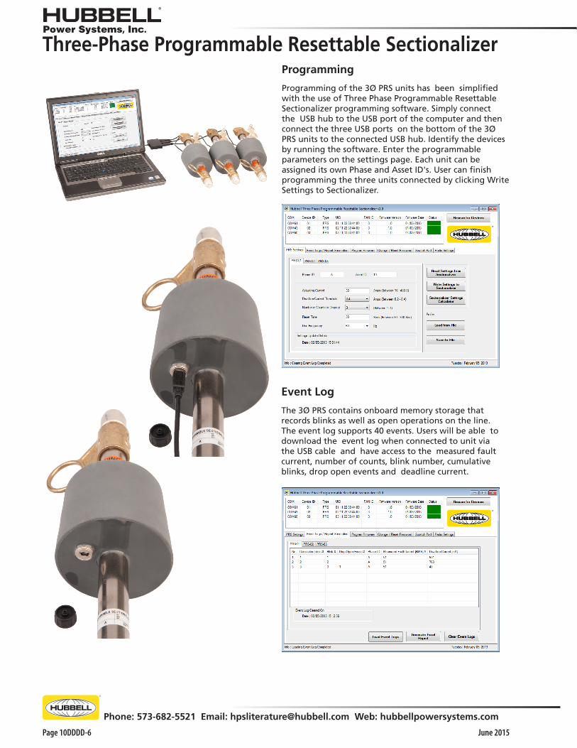
Programming of the 3Ø PRS units has been simplified with the use of Three Phase Programmable Resettable Sectionalizer programming software. Simply connect the USB hub to the USB port of the computer and then connect the three USB ports on the bottom of the 3Ø PRS units to the connected USB hub. Identify the devices by running the software. Enter the programmable parameters on the settings page. Each unit can be assigned its own Phase and Asset ID's. User can finish programming the three units connected by clicking Write Settings to Sectionalizer.
Event Log
The 3Ø PRS contains onboard memory storage that records blinks as well as open operations on the line. The event log supports 40 events. Users will be able to download the event log when connected to unit via the USB cable and have access to the measured fault current, number of counts, blink number, cumulative blinks, drop open events and deadline current.
Three-Phase Programmable Resettable Sectionalizer

June 2015
Phone: 573-682-5521 Email: [email protected] Web: hubbellpowersystems.com
Page 10DDDD-7
POLYMER CutoutCatalog Number System
CP7
4 = Non-Loadbreak
5 = Loadbreak
Position 3:Cutout Type
4 10 1 B PP
Position 9:Cutout Terminal Connectors
P = Parallel-grooveE = Small eyeboltL = Large eyebolt†T = Electronic Module Only
L
Examples:• To order 27kV Polymer cutout programmable sectionalizer with extended bracket and large eyebolt connectors = CP74102PPLX.• To order 27kV programmable sectionalizer module only = C74102PPT.†To order programmable sectionalizer module only, replace "CP7" with "C7" followed by selections for Positions 3 through 9.
Universal Cutout ToolIdeal for use with Standard Electronic Sectionalizer to easily lift out, place, *open and close. Inverted, secure method also fits 100 amp fuse holders of ABB, Chance, S&C cutouts.
Cat. No. PSC4033484 (Wt. 4 oz.)See Tools Catalog Section 2100. *When opening a cutout, follow allwork rules and OSHA regulations.Not for use with Loadbreak cutouts.
Position 10:Cutout Bracket
Z = No bracketB = NEMA B bracketD = D bracketX = Extended bracketBlank = Electronic Module OnlyV = Easy-On Bracket
1 = 15kV, 110kV BIL
2 = 27kV, 125kV BIL (Non-loadbreak only)
15/27kV, 125kV BIL (Loadbreak only)
Position 6:Cutout Insulation Level
Three-Phase Programmable Resettable Sectionalizer
3 USB Cables and 1 USB hubCat. No. PSC7410021
(must order separately)
Silver-platedtop contact
Nickel platedcopper tube
Electronics
Hookstick ring
Lowertube casting
Upper tube casting
Hookstickring
Trunnion
Lower contact
USB port
LatchingDevice

June 2015Page 10DDDD-8
Phone: 573-682-5521 Email: [email protected] Web: hubbellpowersystems.com
PORCELAIN CutoutCatalog Number System
C7
4 = Non-Loadbreak
5 = Loadbreak
Position 3:Cutout Type
4 10 1 B PP
Position 9:Cutout Terminal Connectors
P = Parallel-grooveE = Small eyeboltL = Large eyeboltT = Electronic Module Only
L Position 10:Cutout Bracket
Z = No bracketB = NEMA B bracketD = D bracketX = Extended bracketBlank = Electronic Module OnlyV = Easy-On Bracket
1 = 15kV, 110kV BIL2 = 27kV, 125kV BIL (Non-loadbreak only)
15/27kV, 125kV BIL (Loadbreak only)3 = 38kV, 150kV BIL (Non-loadbreak only)6 = 38kV, 170kV BIL (Non-loadbreak only)
Position 6:Cutout Insulation Level
Universal Cutout ToolIdeal for use with Standard Electronic Sectionalizer to easily lift out, place, *open and close. Inverted, secure method also fits 100 amp fuse holders of ABB, Chance, S&C cutouts.
Cat. No. PSC4033484 (Wt. 4 oz.)See Tools Catalog Section 2100. *When opening a cutout, follow allwork rules and OSHA regulations.Not for use with Loadbreak cutouts.
Examples:To order 38kV, 170kV BIL Porcelain cutout programmable sectionalizer with extended bracket and large eyebolt connectors = C74106PPLX.
To order 38kV, 170kV BIL programmable sectionalizer module only = C74106PPT.
Three-Phase Programmable Resettable Sectionalizer
3 USB Cables and 1 USB hubCat. No. PSC7410021
(must order separately)
Silver-platedtop contact
Nickel platedcopper tube
Electronics
Hookstick ring
Lowertube casting
Upper tube casting
Hookstickring
Trunnion
Lower contact
USB port
LatchingDevice

June 2015
Phone: 573-682-5521 Email: [email protected] Web: hubbellpowersystems.com
Page 10DDDD-9
Accessories
Catalog No.T7001325T7001326T7001327
Terminal ConnectorsMin. Order Qty.
101010
DescriptionParallel-Groove Clamp, tin-plated bronze for No. 6 solid thru 4/0 ACSR or 250 kcmil strandedSmall Eyebolt for No. 8 solid thru 2/0 strandedLarge Eyebolt for No. 6 solid thru 4/0 ACSR or 250 kcmil stranded
C2060283C2060280C2060299C2060632
PSC2060887
Mounting Brackets————
NEMA Heavy Duty “B” Bracket with 11/2" captive bolt for crossarm mountingExtended Crossarm Bracket (Horizontal section is 25/8" longer than NEMA “B” bracket)“D” Pole Mounting BracketCutout/Arrester Bracket complete with carriage bolts and backstrap“V” Easy-On Bracket for Crossarm Height range: 41⁄8” to 55⁄32”, Crossarm Width range: 23⁄4” to 4”
Mounting Bracket Dimensions
Wt. (lb./kg.)0.33 / 0.150.16 / 0.070.40 / 0.14
2.84 / 1.293.75 / 1.707.67 / 3.484.00 / 1.812.9/ 1.32
“V”EASY-ONBRACKET
2.6 IN 67 MM
8.2 IN 208 MM

June 2015Page 10DDDD-10
Phone: 573-682-5521 Email: [email protected] Web: hubbellpowersystems.com
NOTES

June 2015
Phone: 573-682-5521 Email: [email protected] Web: hubbellpowersystems.com
Page 10DDDD-11
NOTES

June 2015Page 10DDDD-12
Phone: 573-682-5521 Email: [email protected] Web: hubbellpowersystems.com
• 8100 Churchill Avenue • Leeds, Alabama 35094 • (205) 699-0840
NEVER COMPROMISE™
www.hubbellpowersystems.com
NOTE: Hubbell has a policy of continuous product improvement. Please visit hubbellpowersystems.com to confirm current design specifications. ©Copyright 2013 Hubbell Incorporated
JUNE 2015 Catalog 10DDDD
NOTICE: For the latest revision of our Catalog and Literature, click here or visit our web site: www.hubbellpowersystems.com