thumbnail - download.e-bookshelf.dea latch or flip-flop is a bistable circuit that is most often...
TRANSCRIPT

Digital Electronics 2
Series Editor Robert Baptiste
Sequential and Arithmetic Logic Circuits
Digital Electronics 2
Tertulien Ndjountche
Contents
Preface ix
Chapter 1 Latch and Flip-Flop 1
11 Introduction 112 General overview 1
121 SR latch 6122 S R latch 9123 Application switch debouncing 11
13 Gated SR latch 11131 Implementation based on an SR latch 12132 Implementation based on an S R latch 14
14 Gated D latch 1515 Basic JK flip-flop 1616 T flip-flop 1817 Master-slave and edge-triggered flip-flop 20
171 Master-slave flip-flop 20172 Edge-triggered flip-flop 24
18 Flip-flops with asynchronous inputs 3019 Operational characteristics of flip-flops 33110 Exercises 34111 Solutions 39
Chapter 2 Binary Counters 51
21 Introduction 5122 Modulo 4 counter 5223 Modulo 8 counter 5324 Modulo 16 counter 55
241 Modulo 10 counter 57
vi Digital Electronics 2
25 Counter with parallel load 6026 Down counter 6227 Synchronous reversible counter 6428 Decoding a down counter 6529 Exercises 66210 Solutions 73
Chapter 3 Shift Register 85
31 Introduction 8532 Serial-in shift register 8533 Parallel-in shift register 8534 Bidirectional shift register 8835 Register file 9036 Shift register based counter 91
361 Ring counter 92362 Johnson counter 93363 Linear feedback counter 94
37 Exercises 10138 Solutions 107
Chapter 4 Arithmetic and Logic Circuits 117
41 Introduction 11742 Adder 117
421 Half adder 117422 Full adder 119423 Ripple-carry adder 120424 Carry-lookahead adder 122425 Carry-select adder 124426 Carry-skip adder 125
43 Comparator 12744 Arithmetic and logic unit 12945 Multiplier 136
451 Multiplier of 2-bit unsigned numbers 136452 Multiplier of 4-bit unsigned numbers 137453 Multiplier for signed numbers 138
46 Divider 14347 Exercises 14948 Solutions 158
Chapter 5 Digital Integrated Circuit Technology 177
51 Introduction 17752 Characteristics of the technologies 177
Contents vii
521 Supply voltage 177522 Logic levels 178523 Immunity to noise 178524 Propagation delay 179525 Electric power consumption 179526 Fan-out or load factor 179
53 TTL logic family 180531 Bipolar junction transistor 180532 TTL NAND gate 181533 Integrated TTL circuit 182
54 CMOS logic family 183541 MOSFET transistor 183542 CMOS logic gates 184
55 Open drain logic gates 185551 Three-state buffer 187552 CMOS integrated circuit 188
56 Other logic families 18957 Interfacing circuits of different technologies 18958 Exercises 19059 Solutions 193
Chapter 6 Semiconductor Memory 195
61 Introduction 19562 Memory organization 19563 Operation of a memory 19764 Types of memory 199
641 Non-volatile memory 199642 Volatile memories 202643 Characteristics of the different memory types 207
65 Applications 207651 Memory organization 208652 Applications 209
66 Other types of memory 218661 Ferromagnetic RAM 220662 Content-addressable memory 222663 Sequential access memory 223
67 Exercises 22668 Solutions 230
Chapter 7 Programmable Logic Circuits 245
71 General overview 24572 Programmable logic device 24673 Applications 255
viii Digital Electronics 2
731 Implementation of logic functions 255732 Two-bit adder 257733 Binary-to-BCD and BCD-to-binary converters 263
74 Programmable logic circuits (CPLD and FPGA) 263741 Principle and technology 264742 CPLD 268743 FPGA 270
75 References 27476 Exercises 27577 Solutions 284
Appendix 307
Bibliography 309
Index 311
Preface
The omnipresence of electronic devices in everyday life is accompanied by thesize reduction and the ever-increasing complexity of digital circuits Thiscomprehensive and easy-to-understand work deals with basic principles of digitalelectronics and allows the reader to grasp the subtleties of digital circuits from logicgates to finite-state machines It presents all the aspects related to combinationallogic and sequential logic It introduces techniques to establish in a simple andconcise manner logic equations as well as methods for the analysis and design ofdigital circuits Emphasis has been especially laid on design approaches that can beused to ensure a reliable operation of finite-state machines Various programmablelogic circuit structures and their applications are also presented Each chapterincludes practical examples and well-designed exercises with worked solutions
This series of books discusses all the different aspects of digital electronicsfollowing a descriptive approach combined with a gradual detailed andcomprehensive presentation of basic concepts The principles of combinational andsequential logic are presented as well as the underlying techniques for the analysis anddesign of digital circuits The analysis and design of digital circuits with increasingcomplexity is facilitated by the use of abstractions at the circuit and architecture levelsThis work consists of three volumes devoted to the following subjects
1) combinational logic circuits
2) sequential and arithmetic logic circuits
3) finite state machines
A progressive approach has been chosen and the chapters are relativelyindependent of each other To help master the subject matter and put into practice thedifferent concepts and techniques topics are complemented by a selection ofexercises with solutions
x Digital Electronics 2
P1 Summary
Volume 2 deals with sequential circuits and arithmetic and logic circuits The logicstate of the output of a sequential logic circuit can depend at any given time on theinputs but also on the previous logic state of the outputs Depending on whether aclock signal is used to synchronize the output state change or not a sequential circuitis said to be synchronous or asynchronous Arithmetic circuits can be used to performaddition subtraction multiplication and division operations on digital data Volume 2contains the following seven chapters
1) Latch and Flip-flop
2) Binary Counters
3) Shift Registers
4) Arithmetic and Logic Circuits
5) Digital Integrated Circuit Technology
6) Semiconductor Memory
7) Programmable Logic Circuits
P2 The reader
This work is an indispensable tool for all engineering students on a bachelors ormasters course who wish to acquire detailed and practical knowledge of digitalelectronics It is detailed enough to serve as a reference for electronic automationand computer engineers
Tertulien NDJOUNTCHEJune 2016
1
Latch and Flip-Flop
11 Introduction
A latch or flip-flop is a bistable circuit that is most often used in applications thatrequire data storage Its chief characteristic is that the output is not dependent solelyon the present state of the input but also on the preceding output state A bistablecircuit has two complementary outputs that can assume either of the two logic levels0 or 1
There are several common types of latches and flip-flops Latches often have nodedicated input for the clock signal They can be combined to implementlevel-triggered and edge-triggered flip-flops Flip-flops can be triggered by one of thelevels or one of the edges of a clock signal (or a digital signal)
12 General overview
A simple latch can be implemented using two NOR or two NAND logic gates
A NOR gate based latch with initial conditions specified is represented inFigure 11(a) The characteristic equation for each of the outputs is determined byassuming that the logic gates have different propagation times1 and this may bemodeled as for a delay Δ between a signal that becomes available at the output andthe feedback signal applied to the input In this way the logic circuit of the latch asillustrated in Figure 11(b) may be transformed as shown in Figures 11(c)and 11(d)
1 Propagation delays in logic gates are assumed to take the form 1 and 1 + Δ respectively
Digital Electronics 2 Sequential and Arithmetic Logic Circuits First Edition Tertulien Ndjountche copy ISTE Ltd 2016 Published by ISTE Ltd and John Wiley amp Sons Inc
2 Digital Electronics 2
(c)
(d)
X
A
B
Y
X+(b)
B X
AY Y+
A
B
Y
X
(a)
0 1
00
A
B
Y
X
Figure 11 a) NOR gate based latch with initial conditions specified b)
logic circuit for the latch and representations useful for the
determination of c) Y + and d) X+
Referring to Figure 11(c) we can write
X = B + Y [11]
Y + = A+X [12]
Substituting [11] into [12] yields
Y + = A+B + Y [13]
= A middotB + Y
= A middot (B + Y )
= A middotB +A middot Y [14]
Similarly the circuit shown in Figure 11(d) can be characterized using thefollowing logic equations
X+ = B + Y [15]
Y = A+X [16]
By substituting [15] into [16] we have
X+ = B +A+X [17]
= B middotA+X
= B middot (A+X)
= A middotB +B middotX [18]
Latch and Flip-Flop 3
The characteristic equations of the NOR gate based latch are thus given by
X+ = A middotB +B middotX [19]
and
Y + = A middotB +A middot Y [110]
A B X X+ Y +
0 0 0 0 10 0 1 1 00 1 0 1 00 1 1 1 01 0 0 0 11 0 1 0 11 1 0 0 01 1 1 0 0
Table 11 State table of the NOR gate based latch
For each output the next state X+ or Y + depends on the present state X or Y In addition to the characteristic equations the initial conditions must be specified todetermine the operation of the latch Table 11 gives the state table for the latch
It must be noted that the two signals X+ and Y + are complementary except whenboth inputs A and B are set to 1
Additionally if the inputs A and B are simultaneously set to 0 the outputs canno longer be defined in a unique manner as the characteristic equations are verifiedby (XY ) = (1 0) or by (XY ) = (0 1) It is therefore impossible to predict thecombination of the states held by the outputs
In practice sequential circuits are most often made to operate in the fundamentalmode This means that only one input can change states at any time On the otherhand because of the difference in propagation delays between the logic gates it isimpossible to guarantee a simultaneous change in the state of two variables Thusthe outputs of the latch are defined by (XY ) = (0 1) when A is first set to 0 orby (XY ) = (1 0) when B is first set to 0 In this case the final state of the circuitis determined by the transient behavior which depends on the order in which thestate changes of the inputs take place In general if shifting from one state to anotherrequires a change in at least two state variables then a race condition will occur
4 Digital Electronics 2
The race is said to be non-critical if the order in which the variables change statedoes not affect the final state of the circuit
If on the contrary the circuit can assume two or more stable states depending onthe order in which the variables change state the race is said to be critical
B
(b)
(d)
Y
X+X
X
Y+Y
X
Y
(c)
1
1 0
1
(a)
B
A
BB
A
A
A
X
Y
Figure 12 a) NAND gate based latch with initial conditions specified
b) logic circuit of the latch and representations useful for the
determination of c) X+ and d) Y +
A NAND gate based latch with initial conditions specified is illustrated inFigure 12(a) Taking into account the fact that the differences in propagation delayof the two logic gates may translate into a delay Δ between an output and thefeedback input an equivalence may be established between the latch in Figure 12(b)and each representation shown in Figures 12(c) and 12(d)
The following logic equations may be derived based on the circuit shown inFigure 12(c)
X+ = A middot Y [111]
Y = B middotX [112]
By substituting [112] into [111] we obtain
X+ = A middotB middotX [113]
= A+B middotX= A+B middotX [114]
Latch and Flip-Flop 5
In the case of the circuit shown in Figure 12(d) the logic equations are written asfollows
X = A middot Y [115]
Y + = B middotX [116]
Substituting [115] into [116] we obtain
Y + = B middotA middot Y [117]
= B +A middot Y= B +A middot Y [118]
The characteristic equations of the NAND gate based latch are therefore in thefollowing form
X+ = A+B middotX [119]
and
Y + = B +A middot Y [120]
A B X X+ Y +
1 1 1 1 01 1 0 0 11 0 1 0 11 0 0 0 10 1 1 1 00 1 0 1 00 0 1 1 10 0 0 1 1
Table 12 State table of the NAND gate based latch
The state table of the NAND gate based latch may be constructed as shown inTable 12 based on characteristic equations and initial conditions
We can see that the signals X+ and Y + are complementary except when the twoinputs A and B are set at 0
In addition the signals X+ and Y + are only defined uniquely when the inputs Aand B cannot change states from 0 to 1 simultaneously Thus the outputs of the latch
6 Digital Electronics 2
are defined by (XY ) = (0 1) if the input A is first set to 1 or by (XY ) = (1 0) ifthe input B is first set to 1 In this case as the final state depends on the order in whichthe inputs change states we have a critical race condition
Among the combinations of states that the outputs of the latch can take only thosefor which X+ = X and Y + = Y are said to be stable
121 SR latch
For the SR latch (S stands for set and R for reset) represented in Figure 13 wecan obtain the characteristic equations from equations [19] and [110] as follow
Q+ = R middot S +R middotQ = R middot (S +Q) [121]
and
Q+ = S middotR+ S middotQ = S middot (R+Q) [122]
It must be noted that complementing Q+ does not yield Q+ The state table isgiven in Table 13
Q
S
R
(a) (b)
S
R
Q
Figure 13 SR latch a) logic circuit b) symbol
S R Q Q+ Q+
0 0 0 0 10 0 1 1 00 1 0 0 10 1 1 0 11 0 0 1 01 0 1 1 01 1 0 0 01 1 1 0 0
Table 13 State table of the SR latch
Latch and Flip-Flop 7
S R Q+ Q+
0 0 Q Q No change0 1 0 1 Reset Q+ to 01 0 1 0 Set Q+ to 11 1 0 0 Forbidden state
Table 14 Truth table of the SR latch
An SR latch whose initial condition is specified can also be characterized using thetruth table shown in Table 14 The SR latch is said to be reset-dominant 0 as settingboth inputs to 1 causes the output Q to change to 0
forbidden state
Q
Q
R
S
Figure 14 Timing diagram for the SR latch
Figure 14 shows the timing diagram of the SR latch where the different operatingmodes that appear in the truth table can be observed
S R Q Q+
0 0 0 00 0 1 10 1 0 00 1 1 01 0 0 11 0 1 11 1 0 x1 1 1 x
Table 15 SR latch state table with do not care states
However if the forbidden state (S = R = 1) is considered as a do not care statethe state table takes the form given in Table 15 Constructing a Karnaugh map as
8 Digital Electronics 2
shown in Figure 15 we obtain another version of the characteristic equation givenby
Q+ = S +Q middotR and S middotR = 0 [123]
Q
SR
00 01 11 10
S
0
R
1 1
6
7
x 1
x 1
00
0
0
1
2
3
4
5Q
Figure 15 Karnaugh map for the SR latch For a color version of this
figure see wwwistecoukndjountcheelectronics2zip
This last equation is used for applications where neither of the inputs S and R cantake the state 1
When a transition requires a change in state for at least two variables an analysisbased on Karnaugh maps as shown in Figure 16 is necessary to detect the criticalrace conditions
Q
SR
00 01 11 10
S
0
R
1 1
6
7
0 1
0 1
00
0
0
1
2
3
4
5
(a)
11 01
S changes first
00
11 10
R changes first
00
SR
00 01 11 10
S
0
R
1 1
6
7
0 1
0 1
00
0
0
1
2
3
4
5
(b)
10 00
S changes first
01 10 11
R changes first
01
Q
Q
Q
Figure 16 Karnaugh map a) critical race b) non-critical race
For a color version of this figure see
wwwistecoukndjountcheelectronics2zip
Latch and Flip-Flop 9
Let us consider that from the initial state where S = 1 R = 1 and Q = 0 andwhich corresponds to the cell 6 in the Karnaugh map of Figure 16(a) both inputs Sand R must be reset to zero
The state of the input S can change before that of the input R or vice versa
The arrows entered in the Karnaugh map are used to illustrate the response of thelatch in each case
In SR terms the transition 11 rarr 01 rarr 00 is produced and the output ismaintained at the final state Q+ = 0 corresponding to cell 0 if the input S changesfirst However if the input R changes first the transition will be 11 rarr 10 rarr 00 andthe final state of the output is then Q+ = 1 corresponding to cell 1
In the case of Figure 16(b) the flip-flop is initially characterized by S = 1 R = 0and Q = 1 this corresponds to the cell 5 in the Karnaugh map
As a result of the possible transitions 10 rarr 00 rarr 01 when S changes first or10 rarr 11 rarr 01 when R changes first the output takes the same final state Q+ = 0corresponding to cells 3 or 2 This corresponds to a non-critical race condition
We can verify that the only critical race condition in an SR latch occurs when theinputs S and R that are initially set to 1 are reset to 0
122 S R latch
An S R latch can be implemented using NAND gates as shown in Figure 17(a)Its symbol is represented in Figure 17(b) Based on the truth table shown in Table 16we can note that the inputs are activated by low-level signals The S R latch is said tobe set-dominant 1 as setting both inputs to 1 changes the output Q to 1
(b)
Q
Q
S
R
(a)
Q
Q
S
R
Figure 17 S R latch a) logic circuit b) symbol
The effect of a race condition on the operation of the latch can be analyzed usinga Karnaugh map
10 Digital Electronics 2
S R Q+ Q+
1 1 Q Q No change1 0 0 1 Reset Q+ to 00 1 1 0 Set Q+ to 10 0 1 1 Forbidden state
Table 16 Truth table of the S R latch
By referring to Figure 18(a) we can see that the flip-flop is initially characterizedby S = 0 and R = 0 and Q = 1 (cell 1) The transition of the inputs S and Rto 1 involves a change in two state variables If due to the difference in propagationdelays the input S changes first this translates to the transitions 00 rarr 10 rarr 11and the final state of the output is Q+ = 0 (cell 6) If on the other hand the input Rchanges first the latch follows the transitions 00 rarr 01 rarr 11 and the output takesthe final state Q+ = 1 (cell 7) This is a critical race condition because the final stateof the outputs depends on the order in which the variables change
R changes first
S
R R
SS R S R
00 01 11 10
0
1 1
6
7
0 0
1 0
11
1
0
1
2
3
4
5
(a)
10 11
00 01 11 10
0
1
6
7
0 0
1 0
11
1
0
1
2
3
4
5
(b)
Q
Q
Q
Q
00
1
10 00 01 10 11 01
S changes first
01 1100S changes first R changes first
Figure 18 Karnaugh map a) critical race b) non-critical race
For a color version of this figure see
wwwistecoukndjountcheelectronics2zip
An example of a non-critical race condition is illustrated by the Karnaugh map asshown in Figure 18(b) Starting from the state S = 1 and R = 0 and Q = 0 (cell 4)the inputs S and R must be set to 0 and 1 respectively The two possible transitions10 rarr 00 rarr 01 (input S changes first) and 10 rarr 11 rarr 01 (input R changes first)lead to the same final state for the output Q+ = 1 (cell 3 or 2)
For the S R latch the only critical race condition occurs when both inputs S andR move from 0 to 1
Latch and Flip-Flop 11
123 Application switch debouncing
Contact bounces of a push-button switch (see Figure 19) during its closing oropening can be eliminated using a S R latch as shown in Figure 110 where VCC
represents the supply voltage and RP is the polarization resistor
Bounces
CC
VCC
Ten
sion
Timet0
To oscilloscope
Triggering
V
Figure 19 Waveform illustrating switch contact bounces
VCC
RPRP
Q
R
S
(b)(a)
S
R
Q
Q
Figure 110 Debouncing switch
When R = 0 the output Q of the latch is set to 1 as soon as the signal S reachesthe logic level 1 for the first time Subsequent fluctuations at the input S no longeraffect the state of Q Similarly when S is at 0 the output Q is reset to 0 following thefirst transition attributing the logic level 1 to R
13 Gated SR latch
A gated or level-sensitive SR latch uses a control signal C that can be a clocksignal The signal C is used to enable (or inhibit) the latch at specific time intervals
12 Digital Electronics 2
131 Implementation based on an SR latch
The gated SR latch in Figure 111(a) is made up of two AND gates and an SRlatch It is represented by the symbol shown in Figure 111(b) It can be characterizedby equations of the form
X+ = A middotB +B middotX [124]
and
Y + = A middotB +A middot Y [125]
where
A = RC B = SC X = Q X+ = Q+ Y = Q
and Y + = Q+ [126]
(b)
Q
QR Q
C
QS
S
R
C
(a)
Figure 111 Gated SR latch based on an SR latch
a) logic circuit b) symbol
The characteristic equations are thus given by
Q+ = S middot C middot (R middot C) + (R middot C) middotQ= R middot S middot C + (R+ C) middotQ [127]
and
Q+ = (S middot C) middotR middot C + (S middot C) middotQ= R middot S middot C + (S + C) middotQ [128]
ndash If C = 0 we have Q+ = Q and Q+ = Q
ndash If C = 1 we have Q+ = R middot (S +Q) and Q+ = S middot (R+Q)
Latch and Flip-Flop 13
Table 17 presents the state table of the gated SR latch based on an SR latch Thetruth table can be constructed as shown in Table 18 An example of the timing diagramis illustrated in Figure 112 for the case where Q = 0 and Q = 1 initially
C S R Q Q+ Q+
0 x x 0 0 10 x x 1 1 01 0 0 0 0 11 0 0 1 1 01 0 1 x 0 11 1 0 x 1 01 1 1 x 0 0
Table 17 State table of the gated SR latch based on an SR latch
C S R Q+ Q+
0 x x Q Q No change1 0 0 Q Q
1 0 1 0 1 Reset1 1 0 1 0 Set1 1 1 0 0 Forbidden state
Table 18 Truth table of the gated SR latch based on an SR latch
forbidden state
S
R
C
Q
Q
Figure 112 Timing diagram of the gated SR latch
14 Digital Electronics 2
132 Implementation based on an S R latch
Another version of the gated SR latch whose logic circuit and symbol are given inFigures 113(a) and 113(b) is implemented using two NAND gates and an S R latchBy performing its analysis the following equations can be derived
X+ = A+B middotX [129]
and
Y + = B +A middot Y [130]
where
A = S middot C B = R middot C X = Q X+ = Q+ Y = Q and Y + = Q+ [131]
and finally we have
Q+ = S middot C + (R+ C) middotQ [132]
and
Q+ = R middot C + (S + C) middotQ [133]
(b)
R Q
C
QS
R
S
C
Q
Q
(a)
Figure 113 Gated SR latch based on an S R latch
a) logic circuit b) symbol
The truth table of the gated SR latch based on an S R latch can therefore beconstructed as shown in Table 19
Latch and Flip-Flop 15
C S R Q+ Q+
0 x x Q Q No change1 0 0 Q Q
1 0 1 0 1 Reset1 1 0 1 0 Set1 1 1 1 1 Forbidden state
Table 19 Truth table of the gated SR latch based on an S R latch
(c)
C
D
Q
Q
(b)
C
D
(a)
Q
QR Q
C
QSD
C
Figure 114 Gated D latch a) and b) logic circuits c) symbol
14 Gated D latch
A gated D latch (D stands for data) can be implemented from a gated SR latch asshown in Figure 114 Connecting an inverter between the S and R inputs prevents theforbidden state from occurring By inserting the expressions
R = D and S = D [134]
in any of the following two characteristic equations of the gated SR latches
Q+ = R middot S middot C + (R+ C) middotQ [135]
and
Q+ = S middot C + (R+ C) middotQ [136]
we obtain for the gated D latch the same characteristic equation given by
Q+ = D middot C +D middotQ+ C middotQ= D middot C middot (Q+Q) +D middot (C + C) middotQ+ (D +D) middot C middotQ= D middot C middot (Q+Q) + C middotQ middot (D +D)
= D middot C + C middotQ [137]
16 Digital Electronics 2
ndash If C = 1 the characteristic equation becomes Q+ = D
ndash If C = 0 we have Q+ = Q
With a gated D latch the state of the input D is transferred to the output when thecontrol (or enable) input C is set to 1 while the state of the output does not changewhen the control input is reset to 0 this translates into a characteristic equation of theform
Q+ = D middot C + C middotQ [138]
The gated D latch is thus said to be transparent when C = 1 It is thereforesensitive to the high level of the signal applied at the input C
Figure 115 shows the symbol of a gated D latch The truth table of a gated D latchis represented in Table 110 where the outputs Q+ and Q+ are complementary Anexample of the timing diagram for the D latch is given in Figure 116 where the outputQ is initially set to 0
QC
QD
Figure 115 Symbol of the gated D latch
C D Q+ Q+
0 x Q Q No change1 0 0 1 Reset1 1 1 0 Set
Table 110 Truth table of the gated D latch
15 Basic JK flip-flop
The JK flip-flop (J as a set input and K as a reset input) is the most versatile of thebasic flip-flops When it is activated it permits the storage of a binary data based on thecombination of states taken by the inputs J and K A JK flip-flop can be implemented
Latch and Flip-Flop 17
by using the logic circuit given in Figure 117(a) It is symbolically represented asshown in Figure 117(b) From the logic circuit of the JK flip-flop we can obtain
S = J middot C middotQ and R = K middot C middotQ [139]
D
C
Q
Figure 116 Timing diagram for the gated D latch
J
QR
QSJ
K
C
(a) (b)
C
QK
Q
Figure 117 Basic JK flip-flop a) logic circuit b) symbol
By inserting these last expressions in the characteristic equation of the gated SRlatch
Q+ = R middot (S +Q) [140]
we get
Q+ = (K middot C middotQ) middot (J middot C middotQ+Q)
= (K + C +Q) middot (J middot C +Q)
= J middotK middot C + J middotQ middot C +K middotQ+Q middot C= (1 + J middot C) middotK middotQ+ (1 +K) middot J middotQ middot C +Q middot C= J middotQ middot C + (K + C) middotQ [141]
ndash if C = 1 the characteristic equation takes the form Q+ = J middotQ+K middotQ
18 Digital Electronics 2
ndash if C = 0 we have Q+ = Q
The state table of the basic JK flip-flop can be constructed as shown in Table 111The forbidden state inherent to the SR latch is eliminated by adding two feedbackpathways in order to ensure that the output will be set to 1 only if Q = 0 and reset to0 only if Q = 1 Table 112 presents the truth table of the basic JK flip-flop where theoutputs Q+ and Q+ are complementary
C J K Q Q+
0 x x x Q1 0 0 0 01 0 0 1 11 0 1 0 01 0 1 1 01 1 0 0 11 1 0 1 11 1 1 0 11 1 1 1 0
Table 111 State table for the JK flip-flop
C J K Q+ Q+
0 x x Q Q No change1 0 0 Q Q
1 0 1 0 1 Reset1 1 0 1 0 Set1 1 1 Q Q Toggle
Table 112 Truth table of the basic JK flip-flop
It must be noted that this JK flip-flop structure may be affected by undesirableoscillations In fact when the two inputs J and K are set at 1 and the clock signalchanges to 1 the feedback of the values Q and Q taken by the outputs forces theflip-flop to toggle (or to switch from one state to its logical complement) And if theclock signal is still at the logic state 1 the process recommences and the flip-flop againchanges state To ensure smooth operation the pulse width of the clock signal mustbe smaller than the propagation delay of the flip-flop
16 T flip-flop
A JK flip-flop can be transformed into a T flip-flop (T stands for toggle) as shownin Figure 118 When the T flip-flop is activated its outputs change state every time a

Digital Electronics 2
Series Editor Robert Baptiste
Sequential and Arithmetic Logic Circuits
Digital Electronics 2
Tertulien Ndjountche
Contents
Preface ix
Chapter 1 Latch and Flip-Flop 1
11 Introduction 112 General overview 1
121 SR latch 6122 S R latch 9123 Application switch debouncing 11
13 Gated SR latch 11131 Implementation based on an SR latch 12132 Implementation based on an S R latch 14
14 Gated D latch 1515 Basic JK flip-flop 1616 T flip-flop 1817 Master-slave and edge-triggered flip-flop 20
171 Master-slave flip-flop 20172 Edge-triggered flip-flop 24
18 Flip-flops with asynchronous inputs 3019 Operational characteristics of flip-flops 33110 Exercises 34111 Solutions 39
Chapter 2 Binary Counters 51
21 Introduction 5122 Modulo 4 counter 5223 Modulo 8 counter 5324 Modulo 16 counter 55
241 Modulo 10 counter 57
vi Digital Electronics 2
25 Counter with parallel load 6026 Down counter 6227 Synchronous reversible counter 6428 Decoding a down counter 6529 Exercises 66210 Solutions 73
Chapter 3 Shift Register 85
31 Introduction 8532 Serial-in shift register 8533 Parallel-in shift register 8534 Bidirectional shift register 8835 Register file 9036 Shift register based counter 91
361 Ring counter 92362 Johnson counter 93363 Linear feedback counter 94
37 Exercises 10138 Solutions 107
Chapter 4 Arithmetic and Logic Circuits 117
41 Introduction 11742 Adder 117
421 Half adder 117422 Full adder 119423 Ripple-carry adder 120424 Carry-lookahead adder 122425 Carry-select adder 124426 Carry-skip adder 125
43 Comparator 12744 Arithmetic and logic unit 12945 Multiplier 136
451 Multiplier of 2-bit unsigned numbers 136452 Multiplier of 4-bit unsigned numbers 137453 Multiplier for signed numbers 138
46 Divider 14347 Exercises 14948 Solutions 158
Chapter 5 Digital Integrated Circuit Technology 177
51 Introduction 17752 Characteristics of the technologies 177
Contents vii
521 Supply voltage 177522 Logic levels 178523 Immunity to noise 178524 Propagation delay 179525 Electric power consumption 179526 Fan-out or load factor 179
53 TTL logic family 180531 Bipolar junction transistor 180532 TTL NAND gate 181533 Integrated TTL circuit 182
54 CMOS logic family 183541 MOSFET transistor 183542 CMOS logic gates 184
55 Open drain logic gates 185551 Three-state buffer 187552 CMOS integrated circuit 188
56 Other logic families 18957 Interfacing circuits of different technologies 18958 Exercises 19059 Solutions 193
Chapter 6 Semiconductor Memory 195
61 Introduction 19562 Memory organization 19563 Operation of a memory 19764 Types of memory 199
641 Non-volatile memory 199642 Volatile memories 202643 Characteristics of the different memory types 207
65 Applications 207651 Memory organization 208652 Applications 209
66 Other types of memory 218661 Ferromagnetic RAM 220662 Content-addressable memory 222663 Sequential access memory 223
67 Exercises 22668 Solutions 230
Chapter 7 Programmable Logic Circuits 245
71 General overview 24572 Programmable logic device 24673 Applications 255
viii Digital Electronics 2
731 Implementation of logic functions 255732 Two-bit adder 257733 Binary-to-BCD and BCD-to-binary converters 263
74 Programmable logic circuits (CPLD and FPGA) 263741 Principle and technology 264742 CPLD 268743 FPGA 270
75 References 27476 Exercises 27577 Solutions 284
Appendix 307
Bibliography 309
Index 311
Preface
The omnipresence of electronic devices in everyday life is accompanied by thesize reduction and the ever-increasing complexity of digital circuits Thiscomprehensive and easy-to-understand work deals with basic principles of digitalelectronics and allows the reader to grasp the subtleties of digital circuits from logicgates to finite-state machines It presents all the aspects related to combinationallogic and sequential logic It introduces techniques to establish in a simple andconcise manner logic equations as well as methods for the analysis and design ofdigital circuits Emphasis has been especially laid on design approaches that can beused to ensure a reliable operation of finite-state machines Various programmablelogic circuit structures and their applications are also presented Each chapterincludes practical examples and well-designed exercises with worked solutions
This series of books discusses all the different aspects of digital electronicsfollowing a descriptive approach combined with a gradual detailed andcomprehensive presentation of basic concepts The principles of combinational andsequential logic are presented as well as the underlying techniques for the analysis anddesign of digital circuits The analysis and design of digital circuits with increasingcomplexity is facilitated by the use of abstractions at the circuit and architecture levelsThis work consists of three volumes devoted to the following subjects
1) combinational logic circuits
2) sequential and arithmetic logic circuits
3) finite state machines
A progressive approach has been chosen and the chapters are relativelyindependent of each other To help master the subject matter and put into practice thedifferent concepts and techniques topics are complemented by a selection ofexercises with solutions
x Digital Electronics 2
P1 Summary
Volume 2 deals with sequential circuits and arithmetic and logic circuits The logicstate of the output of a sequential logic circuit can depend at any given time on theinputs but also on the previous logic state of the outputs Depending on whether aclock signal is used to synchronize the output state change or not a sequential circuitis said to be synchronous or asynchronous Arithmetic circuits can be used to performaddition subtraction multiplication and division operations on digital data Volume 2contains the following seven chapters
1) Latch and Flip-flop
2) Binary Counters
3) Shift Registers
4) Arithmetic and Logic Circuits
5) Digital Integrated Circuit Technology
6) Semiconductor Memory
7) Programmable Logic Circuits
P2 The reader
This work is an indispensable tool for all engineering students on a bachelors ormasters course who wish to acquire detailed and practical knowledge of digitalelectronics It is detailed enough to serve as a reference for electronic automationand computer engineers
Tertulien NDJOUNTCHEJune 2016
1
Latch and Flip-Flop
11 Introduction
A latch or flip-flop is a bistable circuit that is most often used in applications thatrequire data storage Its chief characteristic is that the output is not dependent solelyon the present state of the input but also on the preceding output state A bistablecircuit has two complementary outputs that can assume either of the two logic levels0 or 1
There are several common types of latches and flip-flops Latches often have nodedicated input for the clock signal They can be combined to implementlevel-triggered and edge-triggered flip-flops Flip-flops can be triggered by one of thelevels or one of the edges of a clock signal (or a digital signal)
12 General overview
A simple latch can be implemented using two NOR or two NAND logic gates
A NOR gate based latch with initial conditions specified is represented inFigure 11(a) The characteristic equation for each of the outputs is determined byassuming that the logic gates have different propagation times1 and this may bemodeled as for a delay Δ between a signal that becomes available at the output andthe feedback signal applied to the input In this way the logic circuit of the latch asillustrated in Figure 11(b) may be transformed as shown in Figures 11(c)and 11(d)
1 Propagation delays in logic gates are assumed to take the form 1 and 1 + Δ respectively
Digital Electronics 2 Sequential and Arithmetic Logic Circuits First Edition Tertulien Ndjountche copy ISTE Ltd 2016 Published by ISTE Ltd and John Wiley amp Sons Inc
2 Digital Electronics 2
(c)
(d)
X
A
B
Y
X+(b)
B X
AY Y+
A
B
Y
X
(a)
0 1
00
A
B
Y
X
Figure 11 a) NOR gate based latch with initial conditions specified b)
logic circuit for the latch and representations useful for the
determination of c) Y + and d) X+
Referring to Figure 11(c) we can write
X = B + Y [11]
Y + = A+X [12]
Substituting [11] into [12] yields
Y + = A+B + Y [13]
= A middotB + Y
= A middot (B + Y )
= A middotB +A middot Y [14]
Similarly the circuit shown in Figure 11(d) can be characterized using thefollowing logic equations
X+ = B + Y [15]
Y = A+X [16]
By substituting [15] into [16] we have
X+ = B +A+X [17]
= B middotA+X
= B middot (A+X)
= A middotB +B middotX [18]
Latch and Flip-Flop 3
The characteristic equations of the NOR gate based latch are thus given by
X+ = A middotB +B middotX [19]
and
Y + = A middotB +A middot Y [110]
A B X X+ Y +
0 0 0 0 10 0 1 1 00 1 0 1 00 1 1 1 01 0 0 0 11 0 1 0 11 1 0 0 01 1 1 0 0
Table 11 State table of the NOR gate based latch
For each output the next state X+ or Y + depends on the present state X or Y In addition to the characteristic equations the initial conditions must be specified todetermine the operation of the latch Table 11 gives the state table for the latch
It must be noted that the two signals X+ and Y + are complementary except whenboth inputs A and B are set to 1
Additionally if the inputs A and B are simultaneously set to 0 the outputs canno longer be defined in a unique manner as the characteristic equations are verifiedby (XY ) = (1 0) or by (XY ) = (0 1) It is therefore impossible to predict thecombination of the states held by the outputs
In practice sequential circuits are most often made to operate in the fundamentalmode This means that only one input can change states at any time On the otherhand because of the difference in propagation delays between the logic gates it isimpossible to guarantee a simultaneous change in the state of two variables Thusthe outputs of the latch are defined by (XY ) = (0 1) when A is first set to 0 orby (XY ) = (1 0) when B is first set to 0 In this case the final state of the circuitis determined by the transient behavior which depends on the order in which thestate changes of the inputs take place In general if shifting from one state to anotherrequires a change in at least two state variables then a race condition will occur
4 Digital Electronics 2
The race is said to be non-critical if the order in which the variables change statedoes not affect the final state of the circuit
If on the contrary the circuit can assume two or more stable states depending onthe order in which the variables change state the race is said to be critical
B
(b)
(d)
Y
X+X
X
Y+Y
X
Y
(c)
1
1 0
1
(a)
B
A
BB
A
A
A
X
Y
Figure 12 a) NAND gate based latch with initial conditions specified
b) logic circuit of the latch and representations useful for the
determination of c) X+ and d) Y +
A NAND gate based latch with initial conditions specified is illustrated inFigure 12(a) Taking into account the fact that the differences in propagation delayof the two logic gates may translate into a delay Δ between an output and thefeedback input an equivalence may be established between the latch in Figure 12(b)and each representation shown in Figures 12(c) and 12(d)
The following logic equations may be derived based on the circuit shown inFigure 12(c)
X+ = A middot Y [111]
Y = B middotX [112]
By substituting [112] into [111] we obtain
X+ = A middotB middotX [113]
= A+B middotX= A+B middotX [114]
Latch and Flip-Flop 5
In the case of the circuit shown in Figure 12(d) the logic equations are written asfollows
X = A middot Y [115]
Y + = B middotX [116]
Substituting [115] into [116] we obtain
Y + = B middotA middot Y [117]
= B +A middot Y= B +A middot Y [118]
The characteristic equations of the NAND gate based latch are therefore in thefollowing form
X+ = A+B middotX [119]
and
Y + = B +A middot Y [120]
A B X X+ Y +
1 1 1 1 01 1 0 0 11 0 1 0 11 0 0 0 10 1 1 1 00 1 0 1 00 0 1 1 10 0 0 1 1
Table 12 State table of the NAND gate based latch
The state table of the NAND gate based latch may be constructed as shown inTable 12 based on characteristic equations and initial conditions
We can see that the signals X+ and Y + are complementary except when the twoinputs A and B are set at 0
In addition the signals X+ and Y + are only defined uniquely when the inputs Aand B cannot change states from 0 to 1 simultaneously Thus the outputs of the latch
6 Digital Electronics 2
are defined by (XY ) = (0 1) if the input A is first set to 1 or by (XY ) = (1 0) ifthe input B is first set to 1 In this case as the final state depends on the order in whichthe inputs change states we have a critical race condition
Among the combinations of states that the outputs of the latch can take only thosefor which X+ = X and Y + = Y are said to be stable
121 SR latch
For the SR latch (S stands for set and R for reset) represented in Figure 13 wecan obtain the characteristic equations from equations [19] and [110] as follow
Q+ = R middot S +R middotQ = R middot (S +Q) [121]
and
Q+ = S middotR+ S middotQ = S middot (R+Q) [122]
It must be noted that complementing Q+ does not yield Q+ The state table isgiven in Table 13
Q
S
R
(a) (b)
S
R
Q
Figure 13 SR latch a) logic circuit b) symbol
S R Q Q+ Q+
0 0 0 0 10 0 1 1 00 1 0 0 10 1 1 0 11 0 0 1 01 0 1 1 01 1 0 0 01 1 1 0 0
Table 13 State table of the SR latch
Latch and Flip-Flop 7
S R Q+ Q+
0 0 Q Q No change0 1 0 1 Reset Q+ to 01 0 1 0 Set Q+ to 11 1 0 0 Forbidden state
Table 14 Truth table of the SR latch
An SR latch whose initial condition is specified can also be characterized using thetruth table shown in Table 14 The SR latch is said to be reset-dominant 0 as settingboth inputs to 1 causes the output Q to change to 0
forbidden state
Q
Q
R
S
Figure 14 Timing diagram for the SR latch
Figure 14 shows the timing diagram of the SR latch where the different operatingmodes that appear in the truth table can be observed
S R Q Q+
0 0 0 00 0 1 10 1 0 00 1 1 01 0 0 11 0 1 11 1 0 x1 1 1 x
Table 15 SR latch state table with do not care states
However if the forbidden state (S = R = 1) is considered as a do not care statethe state table takes the form given in Table 15 Constructing a Karnaugh map as
8 Digital Electronics 2
shown in Figure 15 we obtain another version of the characteristic equation givenby
Q+ = S +Q middotR and S middotR = 0 [123]
Q
SR
00 01 11 10
S
0
R
1 1
6
7
x 1
x 1
00
0
0
1
2
3
4
5Q
Figure 15 Karnaugh map for the SR latch For a color version of this
figure see wwwistecoukndjountcheelectronics2zip
This last equation is used for applications where neither of the inputs S and R cantake the state 1
When a transition requires a change in state for at least two variables an analysisbased on Karnaugh maps as shown in Figure 16 is necessary to detect the criticalrace conditions
Q
SR
00 01 11 10
S
0
R
1 1
6
7
0 1
0 1
00
0
0
1
2
3
4
5
(a)
11 01
S changes first
00
11 10
R changes first
00
SR
00 01 11 10
S
0
R
1 1
6
7
0 1
0 1
00
0
0
1
2
3
4
5
(b)
10 00
S changes first
01 10 11
R changes first
01
Q
Q
Q
Figure 16 Karnaugh map a) critical race b) non-critical race
For a color version of this figure see
wwwistecoukndjountcheelectronics2zip
Latch and Flip-Flop 9
Let us consider that from the initial state where S = 1 R = 1 and Q = 0 andwhich corresponds to the cell 6 in the Karnaugh map of Figure 16(a) both inputs Sand R must be reset to zero
The state of the input S can change before that of the input R or vice versa
The arrows entered in the Karnaugh map are used to illustrate the response of thelatch in each case
In SR terms the transition 11 rarr 01 rarr 00 is produced and the output ismaintained at the final state Q+ = 0 corresponding to cell 0 if the input S changesfirst However if the input R changes first the transition will be 11 rarr 10 rarr 00 andthe final state of the output is then Q+ = 1 corresponding to cell 1
In the case of Figure 16(b) the flip-flop is initially characterized by S = 1 R = 0and Q = 1 this corresponds to the cell 5 in the Karnaugh map
As a result of the possible transitions 10 rarr 00 rarr 01 when S changes first or10 rarr 11 rarr 01 when R changes first the output takes the same final state Q+ = 0corresponding to cells 3 or 2 This corresponds to a non-critical race condition
We can verify that the only critical race condition in an SR latch occurs when theinputs S and R that are initially set to 1 are reset to 0
122 S R latch
An S R latch can be implemented using NAND gates as shown in Figure 17(a)Its symbol is represented in Figure 17(b) Based on the truth table shown in Table 16we can note that the inputs are activated by low-level signals The S R latch is said tobe set-dominant 1 as setting both inputs to 1 changes the output Q to 1
(b)
Q
Q
S
R
(a)
Q
Q
S
R
Figure 17 S R latch a) logic circuit b) symbol
The effect of a race condition on the operation of the latch can be analyzed usinga Karnaugh map
10 Digital Electronics 2
S R Q+ Q+
1 1 Q Q No change1 0 0 1 Reset Q+ to 00 1 1 0 Set Q+ to 10 0 1 1 Forbidden state
Table 16 Truth table of the S R latch
By referring to Figure 18(a) we can see that the flip-flop is initially characterizedby S = 0 and R = 0 and Q = 1 (cell 1) The transition of the inputs S and Rto 1 involves a change in two state variables If due to the difference in propagationdelays the input S changes first this translates to the transitions 00 rarr 10 rarr 11and the final state of the output is Q+ = 0 (cell 6) If on the other hand the input Rchanges first the latch follows the transitions 00 rarr 01 rarr 11 and the output takesthe final state Q+ = 1 (cell 7) This is a critical race condition because the final stateof the outputs depends on the order in which the variables change
R changes first
S
R R
SS R S R
00 01 11 10
0
1 1
6
7
0 0
1 0
11
1
0
1
2
3
4
5
(a)
10 11
00 01 11 10
0
1
6
7
0 0
1 0
11
1
0
1
2
3
4
5
(b)
Q
Q
Q
Q
00
1
10 00 01 10 11 01
S changes first
01 1100S changes first R changes first
Figure 18 Karnaugh map a) critical race b) non-critical race
For a color version of this figure see
wwwistecoukndjountcheelectronics2zip
An example of a non-critical race condition is illustrated by the Karnaugh map asshown in Figure 18(b) Starting from the state S = 1 and R = 0 and Q = 0 (cell 4)the inputs S and R must be set to 0 and 1 respectively The two possible transitions10 rarr 00 rarr 01 (input S changes first) and 10 rarr 11 rarr 01 (input R changes first)lead to the same final state for the output Q+ = 1 (cell 3 or 2)
For the S R latch the only critical race condition occurs when both inputs S andR move from 0 to 1
Latch and Flip-Flop 11
123 Application switch debouncing
Contact bounces of a push-button switch (see Figure 19) during its closing oropening can be eliminated using a S R latch as shown in Figure 110 where VCC
represents the supply voltage and RP is the polarization resistor
Bounces
CC
VCC
Ten
sion
Timet0
To oscilloscope
Triggering
V
Figure 19 Waveform illustrating switch contact bounces
VCC
RPRP
Q
R
S
(b)(a)
S
R
Q
Q
Figure 110 Debouncing switch
When R = 0 the output Q of the latch is set to 1 as soon as the signal S reachesthe logic level 1 for the first time Subsequent fluctuations at the input S no longeraffect the state of Q Similarly when S is at 0 the output Q is reset to 0 following thefirst transition attributing the logic level 1 to R
13 Gated SR latch
A gated or level-sensitive SR latch uses a control signal C that can be a clocksignal The signal C is used to enable (or inhibit) the latch at specific time intervals
12 Digital Electronics 2
131 Implementation based on an SR latch
The gated SR latch in Figure 111(a) is made up of two AND gates and an SRlatch It is represented by the symbol shown in Figure 111(b) It can be characterizedby equations of the form
X+ = A middotB +B middotX [124]
and
Y + = A middotB +A middot Y [125]
where
A = RC B = SC X = Q X+ = Q+ Y = Q
and Y + = Q+ [126]
(b)
Q
QR Q
C
QS
S
R
C
(a)
Figure 111 Gated SR latch based on an SR latch
a) logic circuit b) symbol
The characteristic equations are thus given by
Q+ = S middot C middot (R middot C) + (R middot C) middotQ= R middot S middot C + (R+ C) middotQ [127]
and
Q+ = (S middot C) middotR middot C + (S middot C) middotQ= R middot S middot C + (S + C) middotQ [128]
ndash If C = 0 we have Q+ = Q and Q+ = Q
ndash If C = 1 we have Q+ = R middot (S +Q) and Q+ = S middot (R+Q)
Latch and Flip-Flop 13
Table 17 presents the state table of the gated SR latch based on an SR latch Thetruth table can be constructed as shown in Table 18 An example of the timing diagramis illustrated in Figure 112 for the case where Q = 0 and Q = 1 initially
C S R Q Q+ Q+
0 x x 0 0 10 x x 1 1 01 0 0 0 0 11 0 0 1 1 01 0 1 x 0 11 1 0 x 1 01 1 1 x 0 0
Table 17 State table of the gated SR latch based on an SR latch
C S R Q+ Q+
0 x x Q Q No change1 0 0 Q Q
1 0 1 0 1 Reset1 1 0 1 0 Set1 1 1 0 0 Forbidden state
Table 18 Truth table of the gated SR latch based on an SR latch
forbidden state
S
R
C
Q
Q
Figure 112 Timing diagram of the gated SR latch
14 Digital Electronics 2
132 Implementation based on an S R latch
Another version of the gated SR latch whose logic circuit and symbol are given inFigures 113(a) and 113(b) is implemented using two NAND gates and an S R latchBy performing its analysis the following equations can be derived
X+ = A+B middotX [129]
and
Y + = B +A middot Y [130]
where
A = S middot C B = R middot C X = Q X+ = Q+ Y = Q and Y + = Q+ [131]
and finally we have
Q+ = S middot C + (R+ C) middotQ [132]
and
Q+ = R middot C + (S + C) middotQ [133]
(b)
R Q
C
QS
R
S
C
Q
Q
(a)
Figure 113 Gated SR latch based on an S R latch
a) logic circuit b) symbol
The truth table of the gated SR latch based on an S R latch can therefore beconstructed as shown in Table 19
Latch and Flip-Flop 15
C S R Q+ Q+
0 x x Q Q No change1 0 0 Q Q
1 0 1 0 1 Reset1 1 0 1 0 Set1 1 1 1 1 Forbidden state
Table 19 Truth table of the gated SR latch based on an S R latch
(c)
C
D
Q
Q
(b)
C
D
(a)
Q
QR Q
C
QSD
C
Figure 114 Gated D latch a) and b) logic circuits c) symbol
14 Gated D latch
A gated D latch (D stands for data) can be implemented from a gated SR latch asshown in Figure 114 Connecting an inverter between the S and R inputs prevents theforbidden state from occurring By inserting the expressions
R = D and S = D [134]
in any of the following two characteristic equations of the gated SR latches
Q+ = R middot S middot C + (R+ C) middotQ [135]
and
Q+ = S middot C + (R+ C) middotQ [136]
we obtain for the gated D latch the same characteristic equation given by
Q+ = D middot C +D middotQ+ C middotQ= D middot C middot (Q+Q) +D middot (C + C) middotQ+ (D +D) middot C middotQ= D middot C middot (Q+Q) + C middotQ middot (D +D)
= D middot C + C middotQ [137]
16 Digital Electronics 2
ndash If C = 1 the characteristic equation becomes Q+ = D
ndash If C = 0 we have Q+ = Q
With a gated D latch the state of the input D is transferred to the output when thecontrol (or enable) input C is set to 1 while the state of the output does not changewhen the control input is reset to 0 this translates into a characteristic equation of theform
Q+ = D middot C + C middotQ [138]
The gated D latch is thus said to be transparent when C = 1 It is thereforesensitive to the high level of the signal applied at the input C
Figure 115 shows the symbol of a gated D latch The truth table of a gated D latchis represented in Table 110 where the outputs Q+ and Q+ are complementary Anexample of the timing diagram for the D latch is given in Figure 116 where the outputQ is initially set to 0
QC
QD
Figure 115 Symbol of the gated D latch
C D Q+ Q+
0 x Q Q No change1 0 0 1 Reset1 1 1 0 Set
Table 110 Truth table of the gated D latch
15 Basic JK flip-flop
The JK flip-flop (J as a set input and K as a reset input) is the most versatile of thebasic flip-flops When it is activated it permits the storage of a binary data based on thecombination of states taken by the inputs J and K A JK flip-flop can be implemented
Latch and Flip-Flop 17
by using the logic circuit given in Figure 117(a) It is symbolically represented asshown in Figure 117(b) From the logic circuit of the JK flip-flop we can obtain
S = J middot C middotQ and R = K middot C middotQ [139]
D
C
Q
Figure 116 Timing diagram for the gated D latch
J
QR
QSJ
K
C
(a) (b)
C
QK
Q
Figure 117 Basic JK flip-flop a) logic circuit b) symbol
By inserting these last expressions in the characteristic equation of the gated SRlatch
Q+ = R middot (S +Q) [140]
we get
Q+ = (K middot C middotQ) middot (J middot C middotQ+Q)
= (K + C +Q) middot (J middot C +Q)
= J middotK middot C + J middotQ middot C +K middotQ+Q middot C= (1 + J middot C) middotK middotQ+ (1 +K) middot J middotQ middot C +Q middot C= J middotQ middot C + (K + C) middotQ [141]
ndash if C = 1 the characteristic equation takes the form Q+ = J middotQ+K middotQ
18 Digital Electronics 2
ndash if C = 0 we have Q+ = Q
The state table of the basic JK flip-flop can be constructed as shown in Table 111The forbidden state inherent to the SR latch is eliminated by adding two feedbackpathways in order to ensure that the output will be set to 1 only if Q = 0 and reset to0 only if Q = 1 Table 112 presents the truth table of the basic JK flip-flop where theoutputs Q+ and Q+ are complementary
C J K Q Q+
0 x x x Q1 0 0 0 01 0 0 1 11 0 1 0 01 0 1 1 01 1 0 0 11 1 0 1 11 1 1 0 11 1 1 1 0
Table 111 State table for the JK flip-flop
C J K Q+ Q+
0 x x Q Q No change1 0 0 Q Q
1 0 1 0 1 Reset1 1 0 1 0 Set1 1 1 Q Q Toggle
Table 112 Truth table of the basic JK flip-flop
It must be noted that this JK flip-flop structure may be affected by undesirableoscillations In fact when the two inputs J and K are set at 1 and the clock signalchanges to 1 the feedback of the values Q and Q taken by the outputs forces theflip-flop to toggle (or to switch from one state to its logical complement) And if theclock signal is still at the logic state 1 the process recommences and the flip-flop againchanges state To ensure smooth operation the pulse width of the clock signal mustbe smaller than the propagation delay of the flip-flop
16 T flip-flop
A JK flip-flop can be transformed into a T flip-flop (T stands for toggle) as shownin Figure 118 When the T flip-flop is activated its outputs change state every time a

1
Latch and Flip-Flop
11 Introduction
A latch or flip-flop is a bistable circuit that is most often used in applications thatrequire data storage Its chief characteristic is that the output is not dependent solelyon the present state of the input but also on the preceding output state A bistablecircuit has two complementary outputs that can assume either of the two logic levels0 or 1
There are several common types of latches and flip-flops Latches often have nodedicated input for the clock signal They can be combined to implementlevel-triggered and edge-triggered flip-flops Flip-flops can be triggered by one of thelevels or one of the edges of a clock signal (or a digital signal)
12 General overview
A simple latch can be implemented using two NOR or two NAND logic gates
A NOR gate based latch with initial conditions specified is represented inFigure 11(a) The characteristic equation for each of the outputs is determined byassuming that the logic gates have different propagation times1 and this may bemodeled as for a delay Δ between a signal that becomes available at the output andthe feedback signal applied to the input In this way the logic circuit of the latch asillustrated in Figure 11(b) may be transformed as shown in Figures 11(c)and 11(d)
1 Propagation delays in logic gates are assumed to take the form 1 and 1 + Δ respectively
Digital Electronics 2 Sequential and Arithmetic Logic Circuits First Edition Tertulien Ndjountche copy ISTE Ltd 2016 Published by ISTE Ltd and John Wiley amp Sons Inc
2 Digital Electronics 2
(c)
(d)
X
A
B
Y
X+(b)
B X
AY Y+
A
B
Y
X
(a)
0 1
00
A
B
Y
X
Figure 11 a) NOR gate based latch with initial conditions specified b)
logic circuit for the latch and representations useful for the
determination of c) Y + and d) X+
Referring to Figure 11(c) we can write
X = B + Y [11]
Y + = A+X [12]
Substituting [11] into [12] yields
Y + = A+B + Y [13]
= A middotB + Y
= A middot (B + Y )
= A middotB +A middot Y [14]
Similarly the circuit shown in Figure 11(d) can be characterized using thefollowing logic equations
X+ = B + Y [15]
Y = A+X [16]
By substituting [15] into [16] we have
X+ = B +A+X [17]
= B middotA+X
= B middot (A+X)
= A middotB +B middotX [18]
Latch and Flip-Flop 3
The characteristic equations of the NOR gate based latch are thus given by
X+ = A middotB +B middotX [19]
and
Y + = A middotB +A middot Y [110]
A B X X+ Y +
0 0 0 0 10 0 1 1 00 1 0 1 00 1 1 1 01 0 0 0 11 0 1 0 11 1 0 0 01 1 1 0 0
Table 11 State table of the NOR gate based latch
For each output the next state X+ or Y + depends on the present state X or Y In addition to the characteristic equations the initial conditions must be specified todetermine the operation of the latch Table 11 gives the state table for the latch
It must be noted that the two signals X+ and Y + are complementary except whenboth inputs A and B are set to 1
Additionally if the inputs A and B are simultaneously set to 0 the outputs canno longer be defined in a unique manner as the characteristic equations are verifiedby (XY ) = (1 0) or by (XY ) = (0 1) It is therefore impossible to predict thecombination of the states held by the outputs
In practice sequential circuits are most often made to operate in the fundamentalmode This means that only one input can change states at any time On the otherhand because of the difference in propagation delays between the logic gates it isimpossible to guarantee a simultaneous change in the state of two variables Thusthe outputs of the latch are defined by (XY ) = (0 1) when A is first set to 0 orby (XY ) = (1 0) when B is first set to 0 In this case the final state of the circuitis determined by the transient behavior which depends on the order in which thestate changes of the inputs take place In general if shifting from one state to anotherrequires a change in at least two state variables then a race condition will occur
4 Digital Electronics 2
The race is said to be non-critical if the order in which the variables change statedoes not affect the final state of the circuit
If on the contrary the circuit can assume two or more stable states depending onthe order in which the variables change state the race is said to be critical
B
(b)
(d)
Y
X+X
X
Y+Y
X
Y
(c)
1
1 0
1
(a)
B
A
BB
A
A
A
X
Y
Figure 12 a) NAND gate based latch with initial conditions specified
b) logic circuit of the latch and representations useful for the
determination of c) X+ and d) Y +
A NAND gate based latch with initial conditions specified is illustrated inFigure 12(a) Taking into account the fact that the differences in propagation delayof the two logic gates may translate into a delay Δ between an output and thefeedback input an equivalence may be established between the latch in Figure 12(b)and each representation shown in Figures 12(c) and 12(d)
The following logic equations may be derived based on the circuit shown inFigure 12(c)
X+ = A middot Y [111]
Y = B middotX [112]
By substituting [112] into [111] we obtain
X+ = A middotB middotX [113]
= A+B middotX= A+B middotX [114]
Latch and Flip-Flop 5
In the case of the circuit shown in Figure 12(d) the logic equations are written asfollows
X = A middot Y [115]
Y + = B middotX [116]
Substituting [115] into [116] we obtain
Y + = B middotA middot Y [117]
= B +A middot Y= B +A middot Y [118]
The characteristic equations of the NAND gate based latch are therefore in thefollowing form
X+ = A+B middotX [119]
and
Y + = B +A middot Y [120]
A B X X+ Y +
1 1 1 1 01 1 0 0 11 0 1 0 11 0 0 0 10 1 1 1 00 1 0 1 00 0 1 1 10 0 0 1 1
Table 12 State table of the NAND gate based latch
The state table of the NAND gate based latch may be constructed as shown inTable 12 based on characteristic equations and initial conditions
We can see that the signals X+ and Y + are complementary except when the twoinputs A and B are set at 0
In addition the signals X+ and Y + are only defined uniquely when the inputs Aand B cannot change states from 0 to 1 simultaneously Thus the outputs of the latch
6 Digital Electronics 2
are defined by (XY ) = (0 1) if the input A is first set to 1 or by (XY ) = (1 0) ifthe input B is first set to 1 In this case as the final state depends on the order in whichthe inputs change states we have a critical race condition
Among the combinations of states that the outputs of the latch can take only thosefor which X+ = X and Y + = Y are said to be stable
121 SR latch
For the SR latch (S stands for set and R for reset) represented in Figure 13 wecan obtain the characteristic equations from equations [19] and [110] as follow
Q+ = R middot S +R middotQ = R middot (S +Q) [121]
and
Q+ = S middotR+ S middotQ = S middot (R+Q) [122]
It must be noted that complementing Q+ does not yield Q+ The state table isgiven in Table 13
Q
S
R
(a) (b)
S
R
Q
Figure 13 SR latch a) logic circuit b) symbol
S R Q Q+ Q+
0 0 0 0 10 0 1 1 00 1 0 0 10 1 1 0 11 0 0 1 01 0 1 1 01 1 0 0 01 1 1 0 0
Table 13 State table of the SR latch
Latch and Flip-Flop 7
S R Q+ Q+
0 0 Q Q No change0 1 0 1 Reset Q+ to 01 0 1 0 Set Q+ to 11 1 0 0 Forbidden state
Table 14 Truth table of the SR latch
An SR latch whose initial condition is specified can also be characterized using thetruth table shown in Table 14 The SR latch is said to be reset-dominant 0 as settingboth inputs to 1 causes the output Q to change to 0
forbidden state
Q
Q
R
S
Figure 14 Timing diagram for the SR latch
Figure 14 shows the timing diagram of the SR latch where the different operatingmodes that appear in the truth table can be observed
S R Q Q+
0 0 0 00 0 1 10 1 0 00 1 1 01 0 0 11 0 1 11 1 0 x1 1 1 x
Table 15 SR latch state table with do not care states
However if the forbidden state (S = R = 1) is considered as a do not care statethe state table takes the form given in Table 15 Constructing a Karnaugh map as
8 Digital Electronics 2
shown in Figure 15 we obtain another version of the characteristic equation givenby
Q+ = S +Q middotR and S middotR = 0 [123]
Q
SR
00 01 11 10
S
0
R
1 1
6
7
x 1
x 1
00
0
0
1
2
3
4
5Q
Figure 15 Karnaugh map for the SR latch For a color version of this
figure see wwwistecoukndjountcheelectronics2zip
This last equation is used for applications where neither of the inputs S and R cantake the state 1
When a transition requires a change in state for at least two variables an analysisbased on Karnaugh maps as shown in Figure 16 is necessary to detect the criticalrace conditions
Q
SR
00 01 11 10
S
0
R
1 1
6
7
0 1
0 1
00
0
0
1
2
3
4
5
(a)
11 01
S changes first
00
11 10
R changes first
00
SR
00 01 11 10
S
0
R
1 1
6
7
0 1
0 1
00
0
0
1
2
3
4
5
(b)
10 00
S changes first
01 10 11
R changes first
01
Q
Q
Q
Figure 16 Karnaugh map a) critical race b) non-critical race
For a color version of this figure see
wwwistecoukndjountcheelectronics2zip
Latch and Flip-Flop 9
Let us consider that from the initial state where S = 1 R = 1 and Q = 0 andwhich corresponds to the cell 6 in the Karnaugh map of Figure 16(a) both inputs Sand R must be reset to zero
The state of the input S can change before that of the input R or vice versa
The arrows entered in the Karnaugh map are used to illustrate the response of thelatch in each case
In SR terms the transition 11 rarr 01 rarr 00 is produced and the output ismaintained at the final state Q+ = 0 corresponding to cell 0 if the input S changesfirst However if the input R changes first the transition will be 11 rarr 10 rarr 00 andthe final state of the output is then Q+ = 1 corresponding to cell 1
In the case of Figure 16(b) the flip-flop is initially characterized by S = 1 R = 0and Q = 1 this corresponds to the cell 5 in the Karnaugh map
As a result of the possible transitions 10 rarr 00 rarr 01 when S changes first or10 rarr 11 rarr 01 when R changes first the output takes the same final state Q+ = 0corresponding to cells 3 or 2 This corresponds to a non-critical race condition
We can verify that the only critical race condition in an SR latch occurs when theinputs S and R that are initially set to 1 are reset to 0
122 S R latch
An S R latch can be implemented using NAND gates as shown in Figure 17(a)Its symbol is represented in Figure 17(b) Based on the truth table shown in Table 16we can note that the inputs are activated by low-level signals The S R latch is said tobe set-dominant 1 as setting both inputs to 1 changes the output Q to 1
(b)
Q
Q
S
R
(a)
Q
Q
S
R
Figure 17 S R latch a) logic circuit b) symbol
The effect of a race condition on the operation of the latch can be analyzed usinga Karnaugh map
10 Digital Electronics 2
S R Q+ Q+
1 1 Q Q No change1 0 0 1 Reset Q+ to 00 1 1 0 Set Q+ to 10 0 1 1 Forbidden state
Table 16 Truth table of the S R latch
By referring to Figure 18(a) we can see that the flip-flop is initially characterizedby S = 0 and R = 0 and Q = 1 (cell 1) The transition of the inputs S and Rto 1 involves a change in two state variables If due to the difference in propagationdelays the input S changes first this translates to the transitions 00 rarr 10 rarr 11and the final state of the output is Q+ = 0 (cell 6) If on the other hand the input Rchanges first the latch follows the transitions 00 rarr 01 rarr 11 and the output takesthe final state Q+ = 1 (cell 7) This is a critical race condition because the final stateof the outputs depends on the order in which the variables change
R changes first
S
R R
SS R S R
00 01 11 10
0
1 1
6
7
0 0
1 0
11
1
0
1
2
3
4
5
(a)
10 11
00 01 11 10
0
1
6
7
0 0
1 0
11
1
0
1
2
3
4
5
(b)
Q
Q
Q
Q
00
1
10 00 01 10 11 01
S changes first
01 1100S changes first R changes first
Figure 18 Karnaugh map a) critical race b) non-critical race
For a color version of this figure see
wwwistecoukndjountcheelectronics2zip
An example of a non-critical race condition is illustrated by the Karnaugh map asshown in Figure 18(b) Starting from the state S = 1 and R = 0 and Q = 0 (cell 4)the inputs S and R must be set to 0 and 1 respectively The two possible transitions10 rarr 00 rarr 01 (input S changes first) and 10 rarr 11 rarr 01 (input R changes first)lead to the same final state for the output Q+ = 1 (cell 3 or 2)
For the S R latch the only critical race condition occurs when both inputs S andR move from 0 to 1
Latch and Flip-Flop 11
123 Application switch debouncing
Contact bounces of a push-button switch (see Figure 19) during its closing oropening can be eliminated using a S R latch as shown in Figure 110 where VCC
represents the supply voltage and RP is the polarization resistor
Bounces
CC
VCC
Ten
sion
Timet0
To oscilloscope
Triggering
V
Figure 19 Waveform illustrating switch contact bounces
VCC
RPRP
Q
R
S
(b)(a)
S
R
Q
Q
Figure 110 Debouncing switch
When R = 0 the output Q of the latch is set to 1 as soon as the signal S reachesthe logic level 1 for the first time Subsequent fluctuations at the input S no longeraffect the state of Q Similarly when S is at 0 the output Q is reset to 0 following thefirst transition attributing the logic level 1 to R
13 Gated SR latch
A gated or level-sensitive SR latch uses a control signal C that can be a clocksignal The signal C is used to enable (or inhibit) the latch at specific time intervals
12 Digital Electronics 2
131 Implementation based on an SR latch
The gated SR latch in Figure 111(a) is made up of two AND gates and an SRlatch It is represented by the symbol shown in Figure 111(b) It can be characterizedby equations of the form
X+ = A middotB +B middotX [124]
and
Y + = A middotB +A middot Y [125]
where
A = RC B = SC X = Q X+ = Q+ Y = Q
and Y + = Q+ [126]
(b)
Q
QR Q
C
QS
S
R
C
(a)
Figure 111 Gated SR latch based on an SR latch
a) logic circuit b) symbol
The characteristic equations are thus given by
Q+ = S middot C middot (R middot C) + (R middot C) middotQ= R middot S middot C + (R+ C) middotQ [127]
and
Q+ = (S middot C) middotR middot C + (S middot C) middotQ= R middot S middot C + (S + C) middotQ [128]
ndash If C = 0 we have Q+ = Q and Q+ = Q
ndash If C = 1 we have Q+ = R middot (S +Q) and Q+ = S middot (R+Q)
Latch and Flip-Flop 13
Table 17 presents the state table of the gated SR latch based on an SR latch Thetruth table can be constructed as shown in Table 18 An example of the timing diagramis illustrated in Figure 112 for the case where Q = 0 and Q = 1 initially
C S R Q Q+ Q+
0 x x 0 0 10 x x 1 1 01 0 0 0 0 11 0 0 1 1 01 0 1 x 0 11 1 0 x 1 01 1 1 x 0 0
Table 17 State table of the gated SR latch based on an SR latch
C S R Q+ Q+
0 x x Q Q No change1 0 0 Q Q
1 0 1 0 1 Reset1 1 0 1 0 Set1 1 1 0 0 Forbidden state
Table 18 Truth table of the gated SR latch based on an SR latch
forbidden state
S
R
C
Q
Q
Figure 112 Timing diagram of the gated SR latch
14 Digital Electronics 2
132 Implementation based on an S R latch
Another version of the gated SR latch whose logic circuit and symbol are given inFigures 113(a) and 113(b) is implemented using two NAND gates and an S R latchBy performing its analysis the following equations can be derived
X+ = A+B middotX [129]
and
Y + = B +A middot Y [130]
where
A = S middot C B = R middot C X = Q X+ = Q+ Y = Q and Y + = Q+ [131]
and finally we have
Q+ = S middot C + (R+ C) middotQ [132]
and
Q+ = R middot C + (S + C) middotQ [133]
(b)
R Q
C
QS
R
S
C
Q
Q
(a)
Figure 113 Gated SR latch based on an S R latch
a) logic circuit b) symbol
The truth table of the gated SR latch based on an S R latch can therefore beconstructed as shown in Table 19
Latch and Flip-Flop 15
C S R Q+ Q+
0 x x Q Q No change1 0 0 Q Q
1 0 1 0 1 Reset1 1 0 1 0 Set1 1 1 1 1 Forbidden state
Table 19 Truth table of the gated SR latch based on an S R latch
(c)
C
D
Q
Q
(b)
C
D
(a)
Q
QR Q
C
QSD
C
Figure 114 Gated D latch a) and b) logic circuits c) symbol
14 Gated D latch
A gated D latch (D stands for data) can be implemented from a gated SR latch asshown in Figure 114 Connecting an inverter between the S and R inputs prevents theforbidden state from occurring By inserting the expressions
R = D and S = D [134]
in any of the following two characteristic equations of the gated SR latches
Q+ = R middot S middot C + (R+ C) middotQ [135]
and
Q+ = S middot C + (R+ C) middotQ [136]
we obtain for the gated D latch the same characteristic equation given by
Q+ = D middot C +D middotQ+ C middotQ= D middot C middot (Q+Q) +D middot (C + C) middotQ+ (D +D) middot C middotQ= D middot C middot (Q+Q) + C middotQ middot (D +D)
= D middot C + C middotQ [137]
16 Digital Electronics 2
ndash If C = 1 the characteristic equation becomes Q+ = D
ndash If C = 0 we have Q+ = Q
With a gated D latch the state of the input D is transferred to the output when thecontrol (or enable) input C is set to 1 while the state of the output does not changewhen the control input is reset to 0 this translates into a characteristic equation of theform
Q+ = D middot C + C middotQ [138]
The gated D latch is thus said to be transparent when C = 1 It is thereforesensitive to the high level of the signal applied at the input C
Figure 115 shows the symbol of a gated D latch The truth table of a gated D latchis represented in Table 110 where the outputs Q+ and Q+ are complementary Anexample of the timing diagram for the D latch is given in Figure 116 where the outputQ is initially set to 0
QC
QD
Figure 115 Symbol of the gated D latch
C D Q+ Q+
0 x Q Q No change1 0 0 1 Reset1 1 1 0 Set
Table 110 Truth table of the gated D latch
15 Basic JK flip-flop
The JK flip-flop (J as a set input and K as a reset input) is the most versatile of thebasic flip-flops When it is activated it permits the storage of a binary data based on thecombination of states taken by the inputs J and K A JK flip-flop can be implemented
Latch and Flip-Flop 17
by using the logic circuit given in Figure 117(a) It is symbolically represented asshown in Figure 117(b) From the logic circuit of the JK flip-flop we can obtain
S = J middot C middotQ and R = K middot C middotQ [139]
D
C
Q
Figure 116 Timing diagram for the gated D latch
J
QR
QSJ
K
C
(a) (b)
C
QK
Q
Figure 117 Basic JK flip-flop a) logic circuit b) symbol
By inserting these last expressions in the characteristic equation of the gated SRlatch
Q+ = R middot (S +Q) [140]
we get
Q+ = (K middot C middotQ) middot (J middot C middotQ+Q)
= (K + C +Q) middot (J middot C +Q)
= J middotK middot C + J middotQ middot C +K middotQ+Q middot C= (1 + J middot C) middotK middotQ+ (1 +K) middot J middotQ middot C +Q middot C= J middotQ middot C + (K + C) middotQ [141]
ndash if C = 1 the characteristic equation takes the form Q+ = J middotQ+K middotQ
18 Digital Electronics 2
ndash if C = 0 we have Q+ = Q
The state table of the basic JK flip-flop can be constructed as shown in Table 111The forbidden state inherent to the SR latch is eliminated by adding two feedbackpathways in order to ensure that the output will be set to 1 only if Q = 0 and reset to0 only if Q = 1 Table 112 presents the truth table of the basic JK flip-flop where theoutputs Q+ and Q+ are complementary
C J K Q Q+
0 x x x Q1 0 0 0 01 0 0 1 11 0 1 0 01 0 1 1 01 1 0 0 11 1 0 1 11 1 1 0 11 1 1 1 0
Table 111 State table for the JK flip-flop
C J K Q+ Q+
0 x x Q Q No change1 0 0 Q Q
1 0 1 0 1 Reset1 1 0 1 0 Set1 1 1 Q Q Toggle
Table 112 Truth table of the basic JK flip-flop
It must be noted that this JK flip-flop structure may be affected by undesirableoscillations In fact when the two inputs J and K are set at 1 and the clock signalchanges to 1 the feedback of the values Q and Q taken by the outputs forces theflip-flop to toggle (or to switch from one state to its logical complement) And if theclock signal is still at the logic state 1 the process recommences and the flip-flop againchanges state To ensure smooth operation the pulse width of the clock signal mustbe smaller than the propagation delay of the flip-flop
16 T flip-flop
A JK flip-flop can be transformed into a T flip-flop (T stands for toggle) as shownin Figure 118 When the T flip-flop is activated its outputs change state every time a
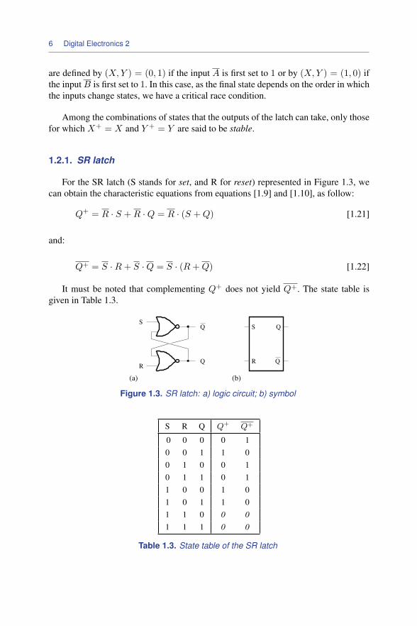
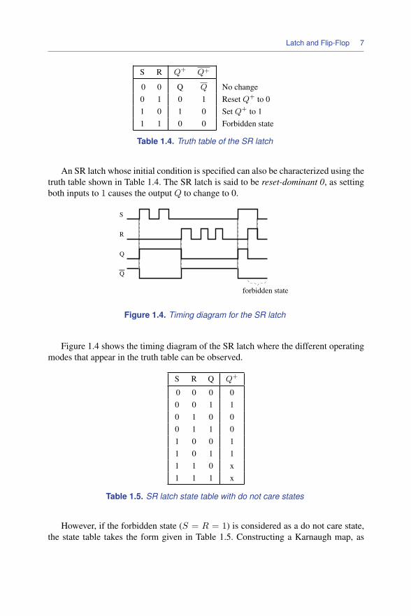