ti dlp system design: brightness requirements … dlp® system design: brightness requirements and...
TRANSCRIPT

1DLPA068A–March 2016–Revised January 2017Submit Documentation Feedback
Copyright © 2016–2017, Texas Instruments Incorporated
TI DLP® System Design: Brightness Requirements and Tradeoffs
Application ReportDLPA068A–March 2016–Revised January 2017
TI DLP® System Design: Brightness Requirements andTradeoffs
Jesse Richuso and Jackson Thomas
ABSTRACTThe objective of this application note is to help product developers who are new to DLP technologyunderstand brightness and the related system tradeoffs.
Prior to reading this application note, it is recommended to read the Getting Started with TI DLP®Technology whitepaper to get a high level understanding of the technology and the applications it enables.
After reading this, check out the DLP Throw Ratio and Brightness Calculator to experiment with projectionspecifications.
Contents1 Introduction ................................................................................................................... 22 Determining the Right Brightness for Your Product ..................................................................... 33 The Impact of Ambient Light Level ........................................................................................ 34 The Impact of Screen Size ................................................................................................. 45 Trade-offs Associated with Brightness .................................................................................... 56 Other Considerations........................................................................................................ 67 Conclusion and Getting Started............................................................................................ 8
List of Figures
1 Suggested Projection Brightness for a Combination of Image Sizes and Image Brightness Levels ............. 42 Simulated Images of High Contrast (Above) and Low Contrast (Below) ............................................. 63 Projection Throw Ratio ...................................................................................................... 7
List of Tables
1 Ambient Lighting and Estimated Minimum Image Brightness in Nits ................................................. 32 Key Projection System Variables and Impacts .......................................................................... 53 Recommended Chipset Portfolio .......................................................................................... 8
TrademarksDLP is a registered trademark of Texas Instruments.All other trademarks are the property of their respective owners.

Introduction www.ti.com
2 DLPA068A–March 2016–Revised January 2017Submit Documentation Feedback
Copyright © 2016–2017, Texas Instruments Incorporated
TI DLP® System Design: Brightness Requirements and Tradeoffs
(1) Projector brightness is technically defined as luminous flux, which is the energy within the visible wavelengths radiated from a source perunit time. The SI unit of luminous flux is the lumen.
(2) ANSI (American National Standards Institute) lumens are measured by averaging the brightness of nine points across the projectedimage, thus taking into account differences in brightness uniformity across different projectors.
(3) Technically, for an arbitrary reflector (surface), Nits = (Lumens × Screen Gain) / (π × m2), but a discussion about screen gain is outsidethe scope of this application note. In this application note, it is being assumed that all reflective surfaces are Lambertian with a screengain of 1 unless otherwise noted.
1 IntroductionBrightness requirements are one of the key considerations to account for when designing any projectionsystem.
The terms “projector brightness” and “image brightness” are used throughout this paper. Here is how theyare defined for the sake of this paper:• Projector brightness (1) is the amount of visible light emitted from a projector or projection system. It is
measured in ANSI (2) lumens (lm) and is independent of image size. With TI DLP technology, it ispossible to create projectors spanning a broad brightness range: From 30 lumens for projectorsembedded into products like smartphones or tablets, to over 10,000 lumens for large venue projectors.Projection systems can include several different types of illumination sources including lamps, LEDs,and lasers. Factors that impact projector brightness include illumination source type (lamp, LED, orlaser), illumination source output capability (radiant watts), illumination source input power (electrical),optical design, and the DLP active array area.
• Image brightness is a measure of the brightness of an image reflected off of a surface. It is measuredin nits (candelas per square meter) and is proportional to lumens per square meter projected onto thesurface. (3) For a fixed display area (image size), the more lumens a system can output, the higher thenits. Likewise, for a fixed number of lumens from the projection system, the smaller the display area,the higher the nits. Image brightness also depends on the projection surface; different surfaces havedifferent reflective characteristics, but exploring the impact and trade-offs of surface characteristic isbeyond the scope of this paper.
The term ‘projector’ can often have limiting connotations. Classically, a projector is a system used only todisplay a video or image on a wall, and while this is still the case, projection systems can be utilized todisplay any form of visuals or infographics on virtually any display surface. These can be used for smarthome displays, digital signage, laser TVs, and many other potential applications. DLP technology enablesprojection systems of many sizes for use in countless applications, in addition to supporting bright, vividdisplays for classically defined projectors.
The two of the most frequently asked questions from customers who are new to TI DLP technology are:“How much brightness is needed for my application?” and “How bright can the projection system get?” Inother words:• What is the right brightness (in lumens) for my product, given the application and user environment?• Given specific power size and cost requirements, what is the maximum brightness that my product can
achieve?
The first question is often asked by product developers for whom image “quality” is the highest priority,whereas the second question is often asked by product developers who have certain technical constraints,most frequently power, size, and/or cost, which will ultimately constrain the maximum brightness of theprojection system.
www.ti.com Determining the Right Brightness for Your Product
3DLPA068A–March 2016–Revised January 2017Submit Documentation Feedback
Copyright © 2016–2017, Texas Instruments Incorporated
TI DLP® System Design: Brightness Requirements and Tradeoffs
2 Determining the Right Brightness for Your ProductAnswering the two most frequently asked questions proposed in Section 1 depends on the followingvariables:• Ambient lighting environment. The ambient light level of the expected use-environment is a critical
factor to consider. For example, with the same projection system, the perceived brightness of a 50-inch(diagonal) image in a well-lit office may be similar to a 100-inch image in a dark room.
• Screen size required. For every 2x increase in the image diagonal (e.g. 20 inch to 40 inch), projectorbrightness (lumens) needs to increase by 4x (e.g. 50 lumens to 200 lumens) in order to maintainconstant image brightness (nits).
• Video content type. The "brighter" the image content (technically, the higher the average picturelevel) or the more "colorful" the image content (technically, the more saturated the colors are), thefewer lumens and/or nits needed to create an image that appears “bright”.
• Projection surface. For the purpose of this application note, a non-glossy, white surface is assumed.For applications requiring a different type of surface, such as a patterned or colored surface, more nitsmay be required.
Ultimately, necessary “brightness” is a subjective assessment. This paper will focus specifically on how aprojection system’s brightness requirement is impacted by ambient light level and screen size.
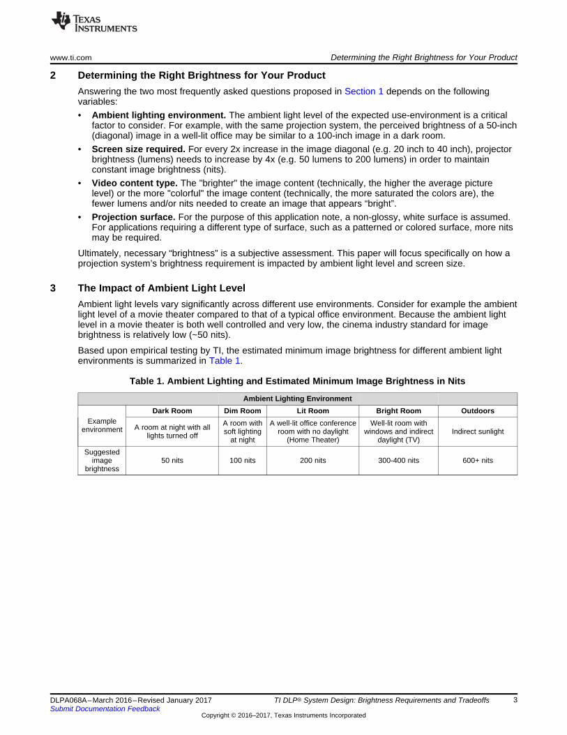
3 The Impact of Ambient Light LevelAmbient light levels vary significantly across different use environments. Consider for example the ambientlight level of a movie theater compared to that of a typical office environment. Because the ambient lightlevel in a movie theater is both well controlled and very low, the cinema industry standard for imagebrightness is relatively low (~50 nits).
Based upon empirical testing by TI, the estimated minimum image brightness for different ambient lightenvironments is summarized in Table 1.
Table 1. Ambient Lighting and Estimated Minimum Image Brightness in Nits
Ambient Lighting Environment
Exampleenvironment
Dark Room Dim Room Lit Room Bright Room Outdoors
A room at night with alllights turned off
A room withsoft lighting
at night
A well-lit office conferenceroom with no daylight
(Home Theater)
Well-lit room withwindows and indirect
daylight (TV)Indirect sunlight
Suggestedimage
brightness50 nits 100 nits 200 nits 300-400 nits 600+ nits

The Impact of Screen Size www.ti.com
4 DLPA068A–March 2016–Revised January 2017Submit Documentation Feedback
Copyright © 2016–2017, Texas Instruments Incorporated
TI DLP® System Design: Brightness Requirements and Tradeoffs
(1) Over time these levels have the potential to increase as new light sources and DMD technology are introduced to the market.
4 The Impact of Screen SizeFigure 1 provides suggested projection brightness (lumens) as a function of diagonal image size andimage brightness (nits) levels from Table 1. Additionally, Figure 1 references the DLP chip class(categorized by the diagonal of the DLP chip micromirror array, called a digital micromirror device or DMD,measured in inches) associated with each brightness level. You can learn more about the DLP productportfolio here.
Figure 1. Suggested Projection Brightness for a Combination of Image Sizes and Image BrightnessLevels
These calculations (1) assume a projection surface with a reflectivity of 80%. When projecting onto a non-ideal surface, the actual lumens desired may be different than those shown above. A typical white wall hasa reflectivity of 80% but colored paints can reduce this number. High gain screens are designed toincrease reflection in a particular viewing direction and can be used to increase image brightness withoutincreasing projection brightness.

www.ti.com Trade-offs Associated with Brightness
5DLPA068A–March 2016–Revised January 2017Submit Documentation Feedback
Copyright © 2016–2017, Texas Instruments Incorporated
TI DLP® System Design: Brightness Requirements and Tradeoffs
5 Trade-offs Associated with BrightnessHow bright can a DLP projection system get? The short answer is "very bright." One of the coreadvantages of DLP technology is its high optical efficiency, enabling bright projection systems with lowpower consumption and compact size. If limitations on size and power are not a factor, you can createdisplays with over 10,000 lumens like the ones used at major sporting events during player introductionsor halftime shows.
However, for this paper, the scope of the question will be limited to "What is the maximum brightness of aDLP projection solution for my size and power requirements?" The answer is “it depends” – there aretradeoffs that can be made at a system design level which depend upon the product design priorities. Tomake a brighter projection solution, it is necessary to also increase one of (or a combination of) thesevariables:
(1) Etendue is a measure of the geometric extent of the light source approximated by the area of the source multiplied by the solidangle of the light emission. Optimum light throughput is usually obtained when the etendue of the source and the DMD are equalwhere the DMD solid angle is determined by the micromirror tilt angle.
Table 2. Key Projection System Variables and Impacts
Variable Contribution LimitationIllumination source output capability Amount of light that can be generated Source and DMD etendue (1)
Optics size Amount of light that can be collected Size and costDMD chip size Amount of light that can be reflected Size and cost
Illumination source drive power Illumination source brightness level Thermal limit and cost ofpower design
Illumination thermal solution Amount of heat dissipated from the illuminationsource Size and cost
For a production-ready optical engine, the first three variables in Table 2 will be constant.
The last two variables in Table 2 (illumination source drive power and the illumination thermal solution)can vary depending on the design requirements of the final product. For example, a given optical modulecan achieve different brightness outputs depending on the current supplied to the LEDs or lasers. Lampshave a fixed power input and output, but can often be switched for higher power bulbs.
DLP technology is flexible and can be used with any illumination source. There are three main types ofillumination typically used in DLP projection systems: lamp, LED, and laser. Lamp sources offer a costeffective solution; LED and laser sources offer high efficiency, solid state illumination. Lamp illumination isoften used in classroom, conference room, and home theater projectors. LED illumination is often found insmall, battery powered projection systems. Laser illumination is used to reduce size and increasebrightness of products ranging from portable displays to high brightness, large venue projections.
For LEDs and lasers, increasing the input power to the illumination source will cause them to output morelight, but also causes more heat to be generated by the illumination system. This necessitates a moreefficient thermal system to keep the illumination sources at their recommended operating temperatures.Therefore, as brightness increases, so does the illumination device temperature, which in turn drives anincrease in the complexity of the illumination thermal system. It is worth noting that higher illuminationsource output will also result in a higher heat load on the DMD. Therefore, at some point, the size of theDMD thermal solution may need to be increased as well.
Additionally, it is important to keep in mind that as the power to the illumination source increases, so doesbrightness, but at a decreasing rate, resulting in increased heat generation. Although illumination powerand brightness varies for different illumination types, all illumination sources will have an optimalbrightness range in which they can operate with maximum efficiency. The thermal management solutionmust be carefully designed to remove the necessary heat from the system while minimizing the impact tothe product’s size and cost.

Other Considerations www.ti.com
6 DLPA068A–March 2016–Revised January 2017Submit Documentation Feedback
Copyright © 2016–2017, Texas Instruments Incorporated
TI DLP® System Design: Brightness Requirements and Tradeoffs
6 Other ConsiderationsWhile brightness, power consumption, and size are typically the most dominant system requirements,there are two additional performance parameters that product developers should consider when designinga DLP projection system: optical engine contrast ratio and projection lens throw ratio.
The contrast ratio of a projection engine impacts the perceived quality of the projected image. The higherthe contrast ratio, the greater the difference between the light and dark areas of the image (see Figure 2).High contrast results in deep blacks and vivid looking colors.
There are two methods of measuring a systems contrast ratio: Full-On / Full-Off (FOFO) Contrast andANSI Contrast. FOFO Contrast is essentially a measurement of the display panels inherent contrast ratio,whereas ANSI Contrast is essentially a measurement of the projection optics contrast ratio. DLPtechnology can enable contrast ratios of over 2,000:1, depending on the projection optics design.
Figure 2. Simulated Images of High Contrast (Above) and Low Contrast (Below)
Projection lens throw ratio relates the size of the projection image to the distance from the projectionsystem to the projection surface, and is defined as D/W, where D is the distance from the projection lensto the projection surface, and W is the width of the projected image. This is illustrated in Figure 3.

www.ti.com Other Considerations
7DLPA068A–March 2016–Revised January 2017Submit Documentation Feedback
Copyright © 2016–2017, Texas Instruments Incorporated
TI DLP® System Design: Brightness Requirements and Tradeoffs
While throw ratio does not impact projector brightness (lumens), it does impact image brightness (nits)from a given projection distance. Two projectors of the same projector brightness (lumens) but withdifferent throw ratios will create different size images when placed the same distance from the viewingsurface. Since the different throw ratios result in different image sizes, the image brightness levels (nits)will also be different. The projector with the shorter throw ratio will create a bigger image, and thus adimmer image because the light (lumens) is be spread out over a larger area. Conversely, the projectorwith the longer throw ratio will create a smaller (and therefore brighter) image. Throw ratio should beconsidered based on the use case of the final product, whether the projection system will be close to theimage or far away from it.
Figure 3. Projection Throw Ratio

Conclusion and Getting Started www.ti.com
8 DLPA068A–March 2016–Revised January 2017Submit Documentation Feedback
Copyright © 2016–2017, Texas Instruments Incorporated
TI DLP® System Design: Brightness Requirements and Tradeoffs
7 Conclusion and Getting StartedDLP technology enables a wide range of brightness capabilities. Designers can influence the brightnesscapability of their DLP projection solution by balancing the product requirements of power consumption,product size, and illumination source selection.
It is important to remember that the brightness requirement of a display is highly dependent on theambient light level in the target environment, desired image size, and the image content (video versusgraphics).
Taken together, these insights can help determine an optimal DLP projection design for a given product.Furthermore, the high optical efficiency and high contrast capability of DLP technology can enable brightand vivid images, even for products with size or power consumption limitations.
Table 3. Recommended Chipset Portfolio
Target Brightness Range Key System Requirements Recommended DLP ChipsetPortfolio
Up to 1,500 lumens Smaller size, lower power DLP Pico DisplayUp to 10,000 lumens Higher brightness DLP Standard Display
DLP Pico chipsets are the smallest, lowest power display chips offered by TI DLP Products. They are agood fit for applications like wearable displays, tablets, smart home displays, after-market head-updisplays, and more. DLP Standard chipsets are larger and therefore enable higher brightness levels. Theyare a good fit for applications such as education and office projectors, large format digital signage, andlaser TVs.
7.1 Steps to Learn More About DLP Technology
1. Learn more about DLP display technology:• Browse getting started resources• Learn about the variety of applications which DLP display technology enables• Browse products and datasheets• Read other technical documents for video and data display
2. Evaluate DLP Pico technology with an easy to use evaluation module (EVM).3. Download TI Designs reference designs to speed product development, including schematics, layout
files, bill of materials, and test reports.• For DLP Pico display technology:
– DLP2010: Ultra Mobile, Ultra Low Power Display Reference Design using DLP Technology– DLP3010: Portable, Low Power HD Projection Display using DLP Technology– DLP4710: Portable, Low Power Full HD Projection Display using DLP® Technology
• For DLP Standard display technology:– DLP660TE: 4K Ultra High Definition (UHD) Display using DLP Technology
4. Browse TI’s E2E community to search for solutions, ask for help, share knowledge, and solveproblems with fellow engineers and TI experts.
5. Find optical modules and design support.• For DLP Pico display technology:
– Buy small quantities of DLP Pico projection optical modules from a distributor– Contact optical module manufacturers for high volume, production-ready optical modules– Contact DLP design houses for custom DLP Pico display technology solutions
• For DLP Standard display technology:– Contact optical module manufacturers for high volume, production-ready optical modules– Contact DLP design networks for custom DLP Standard display technology solutions

www.ti.com Revision History
9DLPA068A–March 2016–Revised January 2017Submit Documentation Feedback
Copyright © 2016–2017, Texas Instruments Incorporated
Revision History
Revision HistoryNOTE: Page numbers for previous revisions may differ from page numbers in the current version.
Changes from Original (March 2016) to A Revision ....................................................................................................... Page
• Updated title to 'TI DLP® System Design: Brightness Requirements and Tradeoffs'............................................ 1• Updated Table 1 and Figure 1 to include higher brightness ranges................................................................ 3• Updated Section 5 to incorporate all light sources.................................................................................... 5• Provided options between DLP Pico and DLP Standard in Section 7 ............................................................. 8

IMPORTANT NOTICE FOR TI DESIGN INFORMATION AND RESOURCES
Texas Instruments Incorporated (‘TI”) technical, application or other design advice, services or information, including, but not limited to,reference designs and materials relating to evaluation modules, (collectively, “TI Resources”) are intended to assist designers who aredeveloping applications that incorporate TI products; by downloading, accessing or using any particular TI Resource in any way, you(individually or, if you are acting on behalf of a company, your company) agree to use it solely for this purpose and subject to the terms ofthis Notice.TI’s provision of TI Resources does not expand or otherwise alter TI’s applicable published warranties or warranty disclaimers for TIproducts, and no additional obligations or liabilities arise from TI providing such TI Resources. TI reserves the right to make corrections,enhancements, improvements and other changes to its TI Resources.You understand and agree that you remain responsible for using your independent analysis, evaluation and judgment in designing yourapplications and that you have full and exclusive responsibility to assure the safety of your applications and compliance of your applications(and of all TI products used in or for your applications) with all applicable regulations, laws and other applicable requirements. Yourepresent that, with respect to your applications, you have all the necessary expertise to create and implement safeguards that (1)anticipate dangerous consequences of failures, (2) monitor failures and their consequences, and (3) lessen the likelihood of failures thatmight cause harm and take appropriate actions. You agree that prior to using or distributing any applications that include TI products, youwill thoroughly test such applications and the functionality of such TI products as used in such applications. TI has not conducted anytesting other than that specifically described in the published documentation for a particular TI Resource.You are authorized to use, copy and modify any individual TI Resource only in connection with the development of applications that includethe TI product(s) identified in such TI Resource. NO OTHER LICENSE, EXPRESS OR IMPLIED, BY ESTOPPEL OR OTHERWISE TOANY OTHER TI INTELLECTUAL PROPERTY RIGHT, AND NO LICENSE TO ANY TECHNOLOGY OR INTELLECTUAL PROPERTYRIGHT OF TI OR ANY THIRD PARTY IS GRANTED HEREIN, including but not limited to any patent right, copyright, mask work right, orother intellectual property right relating to any combination, machine, or process in which TI products or services are used. Informationregarding or referencing third-party products or services does not constitute a license to use such products or services, or a warranty orendorsement thereof. Use of TI Resources may require a license from a third party under the patents or other intellectual property of thethird party, or a license from TI under the patents or other intellectual property of TI.TI RESOURCES ARE PROVIDED “AS IS” AND WITH ALL FAULTS. TI DISCLAIMS ALL OTHER WARRANTIES ORREPRESENTATIONS, EXPRESS OR IMPLIED, REGARDING TI RESOURCES OR USE THEREOF, INCLUDING BUT NOT LIMITED TOACCURACY OR COMPLETENESS, TITLE, ANY EPIDEMIC FAILURE WARRANTY AND ANY IMPLIED WARRANTIES OFMERCHANTABILITY, FITNESS FOR A PARTICULAR PURPOSE, AND NON-INFRINGEMENT OF ANY THIRD PARTY INTELLECTUALPROPERTY RIGHTS.TI SHALL NOT BE LIABLE FOR AND SHALL NOT DEFEND OR INDEMNIFY YOU AGAINST ANY CLAIM, INCLUDING BUT NOTLIMITED TO ANY INFRINGEMENT CLAIM THAT RELATES TO OR IS BASED ON ANY COMBINATION OF PRODUCTS EVEN IFDESCRIBED IN TI RESOURCES OR OTHERWISE. IN NO EVENT SHALL TI BE LIABLE FOR ANY ACTUAL, DIRECT, SPECIAL,COLLATERAL, INDIRECT, PUNITIVE, INCIDENTAL, CONSEQUENTIAL OR EXEMPLARY DAMAGES IN CONNECTION WITH ORARISING OUT OF TI RESOURCES OR USE THEREOF, AND REGARDLESS OF WHETHER TI HAS BEEN ADVISED OF THEPOSSIBILITY OF SUCH DAMAGES.You agree to fully indemnify TI and its representatives against any damages, costs, losses, and/or liabilities arising out of your non-compliance with the terms and provisions of this Notice.This Notice applies to TI Resources. Additional terms apply to the use and purchase of certain types of materials, TI products and services.These include; without limitation, TI’s standard terms for semiconductor products http://www.ti.com/sc/docs/stdterms.htm), evaluationmodules, and samples (http://www.ti.com/sc/docs/sampterms.htm).
Mailing Address: Texas Instruments, Post Office Box 655303, Dallas, Texas 75265Copyright © 2018, Texas Instruments Incorporated