tide gates - golden harvest, · pdf filereaches the design high water level. ... tide gates....
TRANSCRIPT

TIDE GATES
GOLDEN HARVEST, INC.
GH-850-R Restrained Side Hinge Tide GateGH-35 Self-Regulating Tide GateGH-37 Tide-Regulated Tide Gate*
*Manufactured exclusively by Golden Harvest, Inc.Under GHI patent #US 6,779,947
2
Phone: 360-757-4334 Fax: 360-757-1135
FOR TIDAL WETLANDS PRESERVATIONAND RESTORATION
PROPERTY BEHIND DIKES AND LEVEES
FISH, SHELLFISH, WATERFOWL AND WILDLIFE
The Tide Gate is usually mounted to an end wall or cross culvert on the tidal side
adjustable to meet the required gate
In the event of a storm surge the Tide Gate will close and latch automatically and will resume normal water control when the tide returns to normal cycles and levels. The functions of operation are solely dependent upon the goals of the water management agency.
tide the Tide Gate will allow complete discharge of upland storm water runoff
however, are forced closed by the incoming tide preventing saltwater from returning to the wetland. In contrast, the Tide Gate can
thereby feeding essential tide waters to the channel or marsh behind the dike. Because the Tide Gate is located on the outfall or
responds to any tidal change allowing the predetermined amount of water in and closing to incoming water when the tide reaches the design high water level. With the storm tide water elevation, the Tide Gate closes “early” thereby preserving a relatively large volume of potential water storage capacity behind the dike should it be needed for detention of upland runoff associated with the coastal storm. In this way
protection to the upland area while allowing
T IDE GATES

3
MODEL GH-850-R MODEL GH-35MODEL GH-37 TIDE GATES
MODEL GH-850-R
MODEL GH-37
MODEL GH-35

4
General Design
All metal parts shall be stainless steel and shall provide adequate corrosion resistance for the environment. Gate shall be sized for the clear opening. Frame width and height shall be no larger than the outside dimensions of the Box Culvert. Gate shall include neoprene compression seals between the gate and gate frame. Provide all components shown on the Contract Drawings and those needed for proper gate actuation All 316 stainless steel mounting hardware shall be included.
Side-hinged Tidal Actuated Control Gate shall be initially opened using a hydraulic cylinder, crank arm, hydraulic lines, and hydraulic control box as shown on the Contract Drawings. Normal operation
Hydraulic controls shall be housed in a locking, NEMA 4X stainless steel tamper-proof box. Upper and lower gate hinge bearings shall be Gar-Max or equal.
Side-hinged Tidal Actuated Control Gate shall
connection to the hydraulic control box as shown
shall result in release of hydraulic system pressure to components such that gate closure will occur on
hinge tube mounting shall be orientated in an
to facilitate gate closure when the gate hydraulic system pressure is released. Gate opening swing shall provide for a maximum gate opening angle of 70 degrees prior to hydraulic cylinder actuation.
Operating Principles
• Gate start position is fully closed (gate seated
point. In this condition the gate prevents the intrusion of salt water upstream of the closed gate.
•
of tide elevation; this allows drainage during high
•
the degree of open position and continuously locks-out gate closure for every increment of increased
degree of opening to a maximum of seventy degrees.
system provided.• As the tide elevation increases there is an exchange
through the gate of tidal and creek (stream, river,
hydraulic cylinder and allows free movement of the gate in the closing direction. As the tide continues
gate closed and prevent the intrusion of salt water upstream of the closed gate.
MODEL GH-850-RSIDE HINGE TIDE GATEGH-850-R
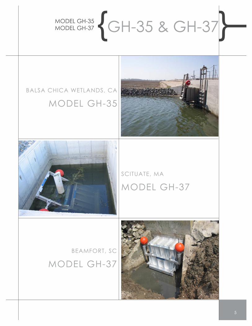
BALSA CHICA WETLANDS, CA
SCITUATE, MA
6
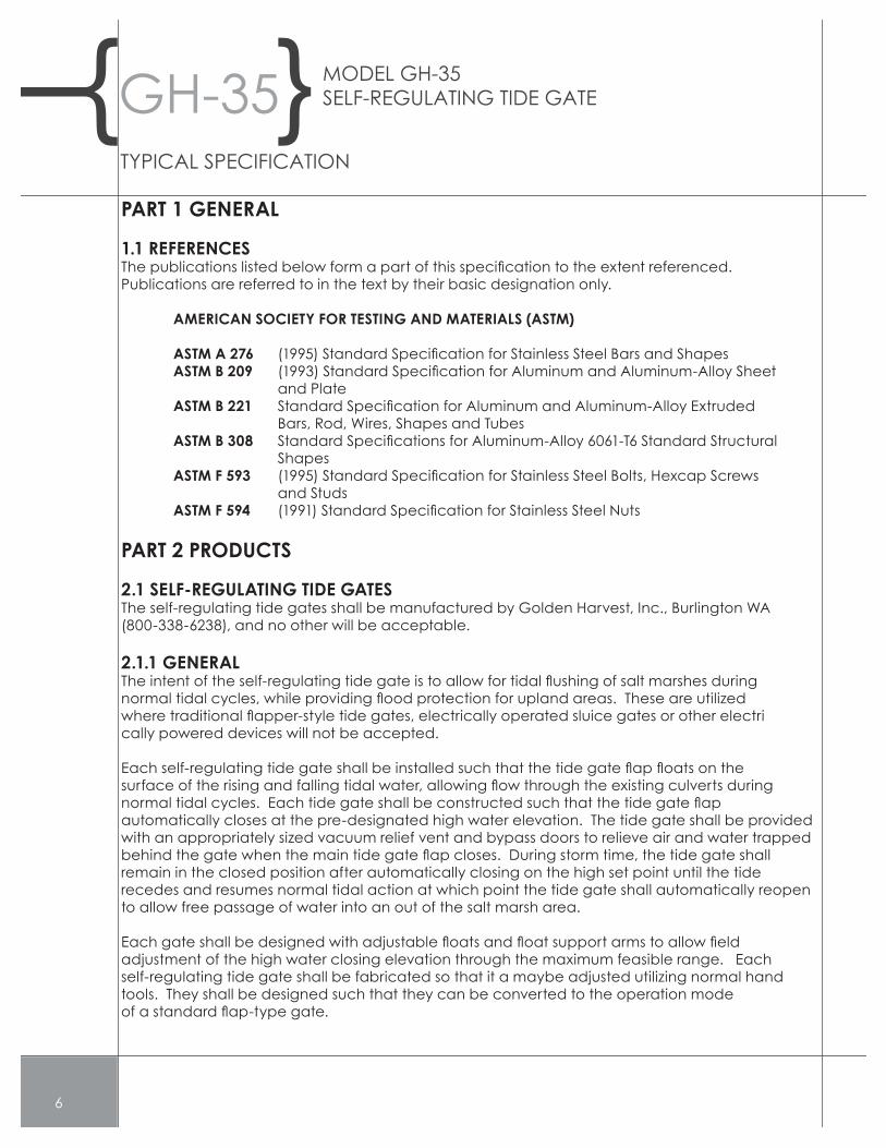
PART 1 GENERAL
1.1 REFERENCES
Publications are referred to in the text by their basic designation only.
and Plate
Shapes
and Studs
cally powered devices will not be accepted.
remain in the closed position after automatically closing on the high set point until the tiderecedes and resumes normal tidal action at which point the tide gate shall automatically reopento allow free passage of water into an out of the salt marsh area.
adjustment of the high water closing elevation through the maximum feasible range. Each
tools. They shall be designed such that they can be converted to the operation mode
TYPICAL SPECIFICATION

7
indicated on the plans, at the locations indicated on the plans.
reinforcement of like material as required to provide structural rigidity.
The bottom interior segment of the tubular body shall be reinforced with a wear plate formed tomatch the bottom of the tubular body. The wear plate shall be permanently attached to theinterior main body of the tide gate structure.
tide gate shall be provided with a neoprene or urethane rubber gasket with factory drilled holes
The tide gate shall be provided with a neoprene molded door gasket.
The lateral bypass doors shall be hinged to open outward from the body of the tide gate.
The vacuum relief vent shall be fabricated from a segment of high density polyethylene tubing
cured to the main body of the tide gate structure.
approved materials suitable for use in salt water.
for use in salt water.

SRT In Normal Tide Sequence
SRT In Storm Sequence

9
Tide-RegulatedFlap Gate Sequence

NOTES

NOTES
11

GOLDEN HARVEST, INC.