ties meter station · metering skid boundary. 5. all isolation mov valves associated with meter...
TRANSCRIPT

Sales Notice TRIPLE 8” METER STATION WITH 16” PROVER LOOP FOR INCOMING OIL
Please contact Walter Boasso for more details at [email protected].
—————

Total Instrument & Electrical Services, Inc. 5363 Highway 311
Houma, Louisiana 70360 Phone (985) 876-2999
Fax (985) 580-3053 Website: www.totalieservices.com
TRIPLE 8” METER STATION WITH 16” PROVER LOOP FOR
INCOMING OIL
TECHNICAL PROPOSAL
Technical Proposal Revision: 000
Issue Date: APRIL 21, 2017 Copy No: Original For any questions or clarifications, Please feel free to contact:
Hien Le Email: [email protected] Office No: +1-985-876-2999 Ext: 206 Mobile: +1-985-709-1140

Technical Proposal
TRIPLE 8” METER STATION WITH 16” PROVER LOOP
FOR INCOMING OIL
TABLE OF CONTENTS I. INTRODUCTION TO TIES
II. PROPOSAL SUMMARY
III. CLARIFICATIONS
IV. SCOPE OF WORK
A. METER STREAM & PIPING
B. PROVER
C. SAMPLING SYSTEM
D. FLOW COMPUTER SYSTEM
V. SPECIFICATIONS
A. STANDARDS
VI. FABRICATION SPECIFICATIONS
A. PROCESS PIPING
B. STRUCTURAL
C. SURFACE PREPARATION AND PAINTING
D. SKID WIRING
E. INSPECTION AND TESTING
VII. DRAWING DELIVERABLES
VIII. ENGINEERING / TECHNICIAN SERVICES
IX. VALIDITY
X. WARRANTY
XI. MAINTENANCE & SUPPORT SERVICES

Technical Proposal
TRIPLE 8” METER STATION WITH 16” PROVER LOOP
FOR INCOMING OIL
I. INTRODUCTION TO TIES
Total Instrument & Electrical Services (TIES) is a Louisiana based business. TIES maintains a dedicated staff of highly qualified and experienced Measurement Engineers, Measurement Technicians, Electricians, Instrumentation Fitters, Instrumentation Technicians, I/E Inspectors, Mechanical Inspectors, and Commissioning Technicians. TIES specializes in Design, Engineering, and Fabrication of Liquid, Gas Metering and Production System, such as LACT Skids, Gas Metering Skids, SCADA Control, PLC Control Systems, HMI Interface Systems and Power Distribution Systems. We have contributed our design and support services to our clients. Our focus is to assist indigenous, marginal field, and other growing operators in their goals of development for oil and gas. We want to be the first name you think of in searching for Metering Systems or any Instrumentation & Electrical application---first in service and first in customer satisfaction. Please be aware that TIES has established a comprehensive safety program within all departments, and at all levels of activity, resulting in a zero accident or OSHA recordable for the past four years in business. In summary, we are committed to ensuring that (1) TIES provides the highest quality of support when possible; (2) these services are provided by qualified, well-trained professionals who are challenged, excited about, and satisfied with their work; and (3) we remember that we can almost do anything right in business, yet we can still fail unless we serve the customer to meet their needs, desires, and expectations. We wish to express our appreciation for the opportunity to serve you. We are available for further consultation at any time should you have a need for further assistance. We look forward to working with you on this and future projects. Should TIES be awarded this project, I know you will be impressed with the quality of our services and workmanship we will provide.
Technical Proposal
TRIPLE 8” METER STATION WITH 16” PROVER LOOP
FOR INCOMING OIL
II. PROPOSAL SUMMARY TIES is pleased with the opportunity to offer our technical skills and experience. Using our experience and knowledge in both application and equipment used for fiscal flow measurement, TIES can provide a successful project outcome. Based on the project’s requirement, we wish to point out our design philosophy for this system. Our key focus is providing our client a metering system with maximum accuracy for long term use. Cost is always an important factor when budgeting for any new project or system. We insure that our clients have the best solution in both accuracy and cost savings. To achieve this goal, our team provides the best system design from the initial stage with the understanding of what our client needs. We also focus in onsite training after completion of our project for operation which maximizes the efficiency use of the complete system. Here is a list of items that we carefully consider when designing our system:
1. METER SELECTION TIES uses a variety of meter types for different applications. For this system, we will be using a positive displacement meter for batching of incoming oil deliveries. A positive displacement meter is a type of flow meter that requires fluid to mechanically displace components in the meter in order for flow measurement. Positive displacement (PD) flow meters measure the volumetric flow rate of a moving fluid or gas by dividing the media into fixed, metered volumes (finite increments or volumes of the fluid). TIES will be using a Smith Meter PD Rotary Vane Meter. It’s principle, combined with the meter’s uniquely designed offset inlet and outlet nozzles, minimizes pressure drop across the measuring chamber, which reduces flow through the meter clearances for maximum accuracy.

Technical Proposal
TRIPLE 8” METER STATION WITH 16” PROVER LOOP
FOR INCOMING OIL
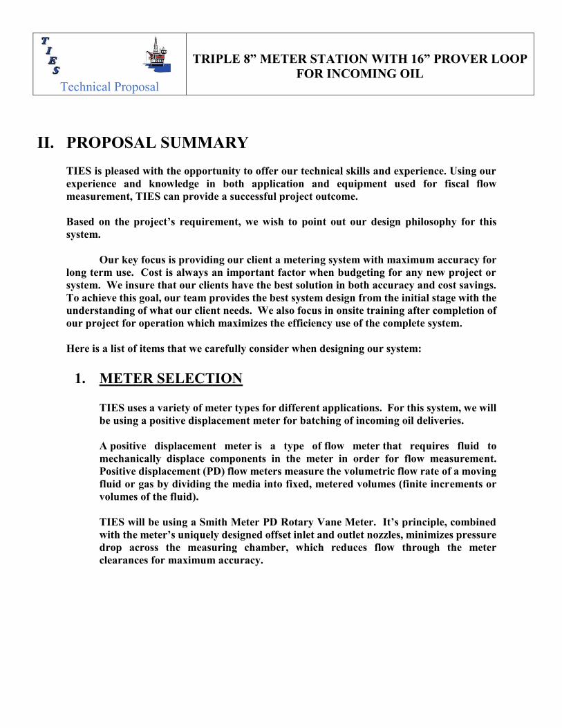
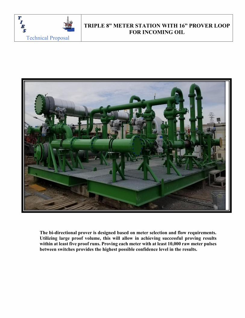
2. SKID LAYOUT
TIES can customize a skid layout to fit any application. This design includes the bi-directional meter prover integration into the metering skid so that no additional deck space is required. A typical layout of this system is shown in the two pictures below:
Technical Proposal
TRIPLE 8” METER STATION WITH 16” PROVER LOOP
FOR INCOMING OIL
The bi-directional prover is designed based on meter selection and flow requirements. Utilizing large proof volume, this will allow in achieving successful proving results within at least five proof runs. Proving each meter with at least 10,000 raw meter pulses between switches provides the highest possible confidence level in the results.
Technical Proposal
TRIPLE 8” METER STATION WITH 16” PROVER LOOP
FOR INCOMING OIL
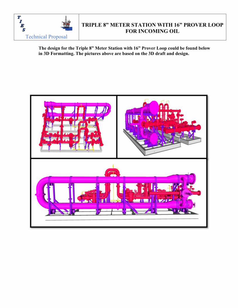
The design for the Triple 8” Meter Station with 16” Prover Loop could be found below in 3D Formatting. The pictures above are based on the 3D draft and design.

Technical Proposal
TRIPLE 8” METER STATION WITH 16” PROVER LOOP
FOR INCOMING OIL
3. SYSTEM UNCERTAINTY
Measurement stability is the most important aspect for achieving a confident level of uncertainty in custody measurement. A metering system with a dedicated meter prover actually provides the means to physically measure the actual system uncertainty rather than just calculating a theoretical value. The system stability is established through multiple meter provings. The historical limits of the resulting Meter Factors define the system uncertainty. If the meter provings are consistently within a repeatability of +/-0.02% (i.e. five (5) proof runs within 0.05%), the overall system will operate with the best possible level of uncertainty. Please note that meter linearity has very little effect on the system uncertainty if the meters are proved at their operating flow rate, and the resulting Meter Factor is applied to the meter reading. Over time, the historical data will establish the parameters over which the meter system will consistently provide a well define level of uncertainty. The meter selection and the prover sizing offered in this proposal are ideal for achieving the most consistent proving results and the highest possible level of measurement precision.
Technical Proposal
TRIPLE 8” METER STATION WITH 16” PROVER LOOP
FOR INCOMING OIL
III. CLARIFICATIONS
1. Any site services to include installation supervision start up and training will be provided at the per diem rates as offered in Financial Section of the Commercial proposal.
2. Prices quoted include complete Installation, Operation, Maintenance Manuals, including, P&ID’s as Built Drawings, & recommended spare parts will be provided.
3. All signal and control wiring on the skids will be wired to junction boxes. Junction boxes will be mounted on the skid edge. All Terminal Boxes located on the Skid shall be c/w minimum of 20% spare terminals.
4. We understand that interconnecting cable between skid junction box and control room shall be supplied by others. We have not considered any cable outside the metering skid boundary.
5. All isolation MOV valves associated with meter proving are “dura/twin seal” type of double block and bleed plug valves. These valves are proven to be the only reliable valve for use in the critical isolation needed in fiscal metering service.
6. FAT is included in this proposal at no additional cost. FAT includes testing of all wiring connections to the junction boxes. The meters will be fully flow tested at the factory test facility. The meter provers will be water draw calibrated at the factory. The instrumentation will be fully operationally tested using simulated inputs for all variables. The meter system receives dynamic flow test.
7. Drip Pans are included under areas where routine maintenance may be required such as under strainers, meters, and prover launch chambers.
8. Normal and Emergency skid lighting is NOT included in the scope of supply.
9. Full Skid drip pans are NOT provided.
10. Insulation is assumed not required based on technical clarifications stating that capability for future installation of insulation shall be provided.
11. The meter system will have uncertainty of +/- 0.3% or better.
12. The meter system will have an availability of 99.9% of the time that it is required to be operational.

Technical Proposal
TRIPLE 8” METER STATION WITH 16” PROVER LOOP
FOR INCOMING OIL
IV. SCOPE OF WORK
A. METER STREAM & PIPING The Design of the Metering Streams and Piping is based on the following Operational Data:
DESIGN CRITERIA FOR TRIPLE 8” INCOMING METERING STATION FLOW RATE (PER METER @ 100%) 2,500 BPH FLOW RATE (SYSTEM DESIGN @ 100%, 1-RUN STANDBY) 5000 BPH FLOW RATE (MAX, 3 RUNS ONLINE) @ 100%) 7500 BPH FLOW RATE (PER METER @ 80%) 2,000 BPH FLOW RATE (SYSTEM DESIGN @ 80%, 1-RUN STANDBY) 4000 BPH FLOW RATE (MAX, 3 RUNS ONLINE) @ 80%) 6000 BPH OPERATING TEMPERATURE MIN 28oC – MAX 38oC DESIGN PRESSURE MAX 275 PSI DENSITY 27-44o API PRODUCT CRUDE OIL (LIQUID) VISCOSITY 14-0.5 cP METER TYPE PD METERS PRESSURE RATING ANSI 150 RF SKID CONFIGURATION 3 X 50% AREA CLASSIFICATION CLASS 1, ZONE 1, GROUPS AB, T3 PROVER 16” BI-DIRECTIONAL PROVER
LOOP, 20” LAUNCH CHAMBERS, 8” 4-WAY VALVE
The meter system will be designed to measure Crude Oil with a maximum design flow rate at 6000 BPH (80%) at maximum working pressure of ANSI 150. A total of three (3) parallel meter runs are provided with two (2) meters on line and one (1) meter as a standby. Each meter run is designed for a normal operating flow rate flow of 2000 BPH @ 80%. 8” size Smith PD Meters have been selected as the best choice for this project. The valves and piping external to the meter run are sized at 8”. The isolation valves are of the “twin seal” block and bleed type to ensure no leakage occurs between the meters and the prover.
Technical Proposal
TRIPLE 8” METER STATION WITH 16” PROVER LOOP
FOR INCOMING OIL
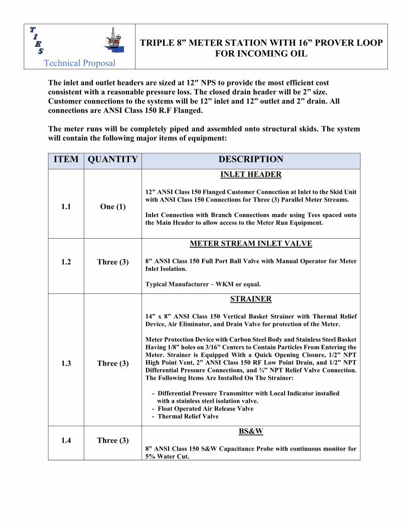
The inlet and outlet headers are sized at 12" NPS to provide the most efficient cost consistent with a reasonable pressure loss. The closed drain header will be 2” size. Customer connections to the systems will be 12” inlet and 12” outlet and 2” drain. All connections are ANSI Class 150 R.F Flanged. The meter runs will be completely piped and assembled onto structural skids. The system will contain the following major items of equipment:
ITEM QUANTITY DESCRIPTION
1.1
One (1)
INLET HEADER
12" ANSI Class 150 Flanged Customer Connection at Inlet to the Skid Unit with ANSI Class 150 Connections for Three (3) Parallel Meter Streams. Inlet Connection with Branch Connections made using Tees spaced onto the Main Header to allow access to the Meter Run Equipment.
1.2
Three (3)
METER STREAM INLET VALVE
8" ANSI Class 150 Full Port Ball Valve with Manual Operator for Meter Inlet Isolation. Typical Manufacturer – WKM or equal.
1.3
Three (3)
STRAINER
14” x 8” ANSI Class 150 Vertical Basket Strainer with Thermal Relief Device, Air Eliminator, and Drain Valve for protection of the Meter. Meter Protection Device with Carbon Steel Body and Stainless Steel Basket Having 1/8” holes on 3/16” Centers to Contain Particles From Entering the Meter. Strainer is Equipped With a Quick Opening Closure, 1/2” NPT High Point Vent, 2” ANSI Class 150 RF Low Point Drain, and 1/2” NPT Differential Pressure Connections, and ¾” NPT Relief Valve Connection. The Following Items Are Installed On The Strainer: - Differential Pressure Transmitter with Local Indicator installed with a stainless steel isolation valve. - Float Operated Air Release Valve - Thermal Relief Valve
1.4
Three (3)
BS&W
8” ANSI Class 150 S&W Capacitance Probe with continuous monitor for 5% Water Cut.

Technical Proposal
TRIPLE 8” METER STATION WITH 16” PROVER LOOP
FOR INCOMING OIL
1.5
Three (3)
METER 8" ANSI Class 150 Smith Meter PD Rotary Vane Meter with Right Angle drive, UPT Pulse Transmitter and a Ticket Counter. The meter is a Double-case, straight-through, rotary vane, positive displacement meter. Linearity is +/- 0.15% over the Meter Catalog Rating of 100 to 2500 BPH While Maintaining A Repeatability of +/-0.02%. UPT Transmitter Meter “K” Factor is 1000 Pulses/BBL.
1.6
Three (3)
PRESSURE GAUGE 4 ½” Diameter Pressure Gauge Installed with a Stainless Steel Isolation Valve. Range to suit operating conditions.
1.7
Three (3)
PRESSURE TRANSMITTER Smart Type Electronic Pressure Transmitter with Local Indicator installed with a Stainless Steel Isolation Valve. Range to suit operating conditions.
1.8
Three (3)
TEMPERATURE INDICATOR 5” Diameter Temperature Gauge with Bi-Metal movement installed with 316 Stainless Steel ¾” NPT Thermowell. Range to suit operation conditions.
1.10
Three (3)
TEMPERATURE TRANSMITTER Smart Type Electronic Temperature Transmitter with Local Indicator installed with a Stainless Steel 3/4” NPT Thermowell. Range to suit operating conditions.
1.11
Three (3)
PROVER INLET ISOLATION VALVE
8" ANSI Class 150 High Integrity Block and Bleed Valve with Electric Actuator for Prover Inlet Isolation. Valve Type: Regular Port Expanding Plug, ASTM A216 Carbon Steel Body with Chrome Plated Bore, Ductile Iron ASTM A395 Plug with ENP Plating, Viton Seals. Design to API 6D. Valve is complete with Differential Relief Assembly and Manual Bleed Valve for checking Seal Integrity. Typical Manufacturer – General Twinseal Valve or equal. Actuator: Explosion Proof Electric, Explosion Proof, Local and Remote Control Typical Manufacturer - Rotork IQ or Limitorque MX.

Technical Proposal
TRIPLE 8” METER STATION WITH 16” PROVER LOOP
FOR INCOMING OIL
1.12
Three (3)
FLOW BALANCING VALVE
8" ANSI Class 150 Vee-Ball Valve With I/P Control for maintaining and balancing flow rate across each meter runs. Valve Type: CS Body, SST Ball and Shaft, TCM Seal, Comp Packing, 1061 Size 60 PD to Fail Open Piston Actuator, RHM POS 1, 377D Trip Valve. I/P: DVC6020-HC Digital Valve Positioner, 4-20 mA in, Increase in mA, 67DFR Regulator set at 60 PSI. 3/8" SST Tubing and Fittings, Inline Check Valve, Mounting Kit, Vol. Bottle for Fail Open Action Typical Manufacturer – Fisher or equal Actuator: Fisher or equal
1.13
Three (3)
METER RUN OUTLET ISOLATION VALVE
8" ANSI Class 150 High Integrity Block and Bleed Valve with Electric Actuator for Meter Run Outlet Isolation. Valve Type: Regular Port Expanding Plug, ASTM A216 Carbon Steel Body with Chrome Plated Bore, Ductile Iron ASTM A395 Plug with ENP Plating, Viton Seals. Design to API 6D. Valve is complete with Differential Relief Assembly and Manual Bleed Valve for checking Seal Integrity. Typical Manufacturer – General Twinseal Valve or equal. Actuator: Explosion Proof Electric, Explosion Proof, Local and Remote Control Typical Manufacturer - Rotork IQ or Limitorque MX.
1.14
One (1)
PROVER RETURN OUTLET VALVE
8" ANSI Class 150 Reduced Port Ball Valve with Electric Operator for Prover Return Outlet Isolation. Typical Manufacturer – WKM or equal. Actuator: Explosion Proof Electric, Explosion Proof, Local and Remote Control Typical Manufacturer - Rotork IQ or Limitorque MX.
1.15
Three (3)
MAIN STREAM CHECK VALVE
8" ANSI Class 150 Horizontal Swing Check Valve Typical Manufacturer – TW or equal.
Technical Proposal
TRIPLE 8” METER STATION WITH 16” PROVER LOOP
FOR INCOMING OIL
1.16
Three (3)
METER STREAM OUTLET VALVE
8" ANSI Class 150 Reduce Port Ball Valve with Manual Operator for Meter Inlet Isolation. Typical Manufacturer – WKM or equal.
1.17
One (1)
OUTLET HEADER
12" ANSI Class 150 Flanged Customer Connection at skid outlet to the skid unit with ANSI Class 150 Connections for Three (3) Parallel Meter Streams. Outlet Connection with Branch Connections made using Tees spaced onto the Main Header to allow access to the Meter Run Equipment.
1.18
One (1)
PROVER INLET HEADER
8" ANSI Class 150 Flanged Inlet Header with ANSI Class 150 Connections to Three (3) Parallel Meter Streams. The Header connects the Meter Run Isolation Valves to the Meter Prover. Branch Connections are made using Tees spaced onto the Main Header to allow access to the Meter Run Equipment.
1.19
One (1)
PROVER OUTLET
8" piping with ANSI Class 150 Flanged Connections to Meter Outlet Header. The Header connects the Prover Outlet line back to the Outlet Header. Branch Connections are made using Tees spaced onto the Main Header to allow access to the Meter Run Equipment.
1.20
One (1)
DRAIN HEADER
2" ANSI Class 150 Flanged Customer Connection at the Skid Edge Unit with ANSI Class 150 Connections to Three (3) Parallel Meter Streams. The Header connects the Meter Runs to a Drain.
1.21
Lot
STRUCTURAL STEEL SKID
Structural Steel shapes configured to support all the Piping and Equipment. Skid includes grated walk areas and/ or elevated walkways as necessary to provide adequate access to all equipment for Operation and Maintenance. Drip pans are included under the strainers and the prover launch chambers.

Technical Proposal
TRIPLE 8” METER STATION WITH 16” PROVER LOOP
FOR INCOMING OIL
Estimated Skid Dimension & Weight will be as follow:
LENGTH WIDTH HEIGHT WEIGHT 47 Feet 15 Feet 13 Feet 50,000 Pounds
14.3 Meters 4.5 Meters 4 Meters 22680 Kg
B. PROVER The meter prover is integrated into the skid structure with the meter runs. It is designed for the maximum flow rate of 2,500 BPH and design pressure of ANSI 150. The meter prover is a bi-directional type, 'U' configuration utilizing a 16 inch measuring section, 20 inch launch/receiving chambers and a 8 inch four-way diverter valve. The prover is sized for a volume of 450 gallons between detector switches and sufficient pre-run piping to allow the four-way diverter valve to be sealed before the spheroid actuates the first detector. This volume is nominal and actual volume will be determined by the water draw method. Four (4) sphere detectors with four (4) distinct prover volumes will be provided. At the maximum meter flow rate, the sphere velocity is 3.07 ft/sec. This is the optimal design velocity and prover size for this application. Length between switches is approximately 47.42 feet to insure repeatability to +/- 0.02%. The prover utilizes a 8” ANSI Class 300 Double Block and Bleed Four-way Diverter valve to control flow through the prover loop. Valve will be supplied with an electrical actuator. The prover pipe and fittings are inspected for ovality, internal smoothness, pits, and grooves prior to fabrication. Internal weld seams are ground smooth. Internal surfaces are sandblasted to white metal and Sakaphen SI 14E or Equivalent baked on epoxy internal coating is applied to provide a smooth, wear resilient path for the spheroid. Flanged joints in the measuring section are specially machined, O-ring seal design with matched bores. This permits re-assembly of the pipe sections with original alignment of parts and maintains the original measuring volume. Matched bores improve prover accuracy and repeatability, and reduce wear on the spheroid. The prover will be complete with two (2) 16 inch Polyurethane spheroids and one (1) 20 inch quick-closure to facilitate sphere inspection and removal. See Prover Calculation below for reference:

Technical Proposal
TRIPLE 8” METER STATION WITH 16” PROVER LOOP
FOR INCOMING OIL
Technical Proposal
TRIPLE 8” METER STATION WITH 16” PROVER LOOP
FOR INCOMING OIL
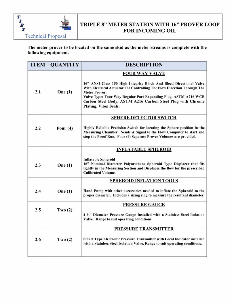
The meter prover to be located on the same skid as the meter streams is complete with the following equipment.
ITEM QUANTITY DESCRIPTION
2.1
One (1)
FOUR WAY VALVE
16" ANSI Class 150 High Integrity Block And Bleed Directional Valve With Electrical Actuator For Controlling The Flow Direction Through The Meter Prover. Valve Type: Four Way Regular Port Expanding Plug, ASTM A216 WCB Carbon Steel Body, ASTM A216 Carbon Steel Plug with Chrome Plating, Viton Seals.
2.2
Four (4)
SPHERE DETECTOR SWITCH
Highly Reliable Precision Switch for locating the Sphere position in the Measuring Chamber. Sends A Signal to the Flow Computer to start and stop the Proof Run. Four (4) Separate Prover Volumes are provided.
2.3
One (1)
INFLATABLE SPHEROID
Inflatable Spheroid 16” Nominal Diameter Polyurethane Spheroid Type Displacer that fits tightly in the Measuring Section and Displaces the flow for the prescribed Calibrated Volume.
2.4
One (1)
SPHEROID INFLATION TOOLS
Hand Pump with other accessories needed to inflate the Spheroid to the proper diameter. Includes a sizing ring to measure the resultant diameter.
2.5
Two (2)
PRESSURE GAUGE 4 ½” Diameter Pressure Gauge Installed with a Stainless Steel Isolation Valve. Range to suit operating conditions.
2.6
Two (2)
PRESSURE TRANSMITTER Smart Type Electronic Pressure Transmitter with Local Indicator installed with a Stainless Steel Isolation Valve. Range to suit operating conditions.

Technical Proposal
TRIPLE 8” METER STATION WITH 16” PROVER LOOP
FOR INCOMING OIL
2.7
Two (2)
TEMPERATURE INDICATOR 5” Diameter Temperature Gauge with Bi-Metal movement installed with 316 Stainless Steel ¾” NPT Thermowell. Range to suit operation conditions.
2.8
Two (2)
TEMPERATURE TRANSMITTER Smart Type Electronic Temperature Transmitter with Local Indicator installed with a Stainless Steel 3/4” NPT Thermowell. Range to suit operating conditions.
2.9
Two (2)
DRAIN VALVE
2" ANSI Class 150 Ball Valve for Prover Drain Isolation. Valve Type: Full Ball, Carbon Steel Body, Carbon Steel Ball with Chrome Plating.
2.10
Two (2)
THERMAL RELIEF VALVE
Carbon Steel ¾” X 1” NPT Relief Valve with Viton Seat for tight shut off. Valve Type: Conventional Spring Loaded, Body Material ASTM A216 Gr. WCB. with 17-4 PH Stainless Steel Trim.
2.11
One (1)
FLOW BALANCING VALVE
8" ANSI Class 150 Vee-Ball Valve With I/P Control for maintaining and balancing flow rate across each meter runs. Valve Type: CS Body, SST Ball and Shaft, TCM Seal, Comp Packing, 1061 Size 60 PD to Fail Open Piston Actuator, RHM POS 1, 377D Trip Valve. I/P: DVC6020-HC Digital Valve Positioner, 4-20 mA in, Increase in mA, 67DFR Regulator set at 60 PSI. 3/8" SST Tubing and Fittings, Inline Check Valve, Mounting Kit, Vol. Bottle for Fail Open Action Typical Manufacturer – Fisher or equal Actuator: Fisher or equal

Technical Proposal
TRIPLE 8” METER STATION WITH 16” PROVER LOOP
FOR INCOMING OIL
2.12
One (1)
PROVER RETURN OUTLET VALVE
8" ANSI Class 150 Reduced Port Ball Valve with Electric Operator for Prover Return Outlet Isolation. Typical Manufacturer – WKM or equal. Actuator: Explosion Proof Electric, Explosion Proof, Local and Remote Control Typical Manufacturer - Rotork IQ or Limitorque MX.
2.13
One (1)
HORTIZONAL LAUNCH CHAMBER WITH CLOSURE
20" ANSI Class 150 Launch Chamber complete with Quick Opening Closure. The Launch Chamber retrieves and then launches the spheroid for each Proof Run. The Quick Opening Closure facilities insertion and removal of the Spheroid for Maintenance.
2.14
One (1)
HORTIZONAL LAUNCH CHAMBER WITH BLIND
20" ANSI Class 150 Launch Chamber with Blind Flanged Closure. The Launch Chamber retrieves and then launches the Spheroid for each Proof Run.
2.15
One (1)
DIFFERENTIAL PRESSURE TRANSMITTER
Smart Type Electronic Differential Pressure Transmitter with local indicator installed with a Stainless Steel Isolation Valve. Range to suit operating conditions. Transmitter monitors the Four Way Seal Integrity during a Proof Run.
2.16
Two (2)
WATERDRAW CONNECTIONS
2" ANSI Class 150 Blind Flanged Connection to facilitate the Prover Calibration Process for future use.
2.17
Two (2)
VENT VALVES
1/2" NPT Vent Valves installed at the High Point on the Launch Chamber to allow for venting air from the Meter Prover Piping.
2.18
Lot
STRUCTURAL STEEL SKID
Structural Steel Beams spaced regularly under the Prover Piping Runs. Drip Pan are provided under the launch chamber with Quick Closure.

Technical Proposal
TRIPLE 8” METER STATION WITH 16” PROVER LOOP
FOR INCOMING OIL
C. SAMPLING SYSTEM A Sample Skid is included with the metering skid for quality measurement. The sample skid unit will be designed to pull product out of a process line, measure its properties, and return it to the same line. The Sample Skid will be provided for tying into a section of the meter stream. A basic arrangement is as follows:
ITEM QUANTITY DESCRIPTION
3.1
Two (2)
AUTO SAMPLING SKID
20-gallon sample pot and containment w/ quick closure and o-ring, static mixer, mixing units, relief valve. Includes indicator for high low alarm and shut off. Will include level gauge on sample pot. Motor for mixing unit will be 1 Phase 120Vac 60 Hertz.
3.2
Three (3)
SAMPLING PROBE
Automatic isokinetic sampling probe that is actuated by an electrical pulse from the controller and uses existing pipeline pressure to fill the sample chamber with product. To be installed on each meter stream.
3.3
Three (3)
STATIC MIXER
A unique flow straightener is built right into each mixer to eliminate any downstream centrifugal effects. This allows sensing probes to be located directly downstream of the unit. To be installed on each meter stream upstream of the sampling probe.

Technical Proposal
TRIPLE 8” METER STATION WITH 16” PROVER LOOP
FOR INCOMING OIL
D. FLOW COMPUTER SYSTEM The flow computer system will not be included in this proposal. This system will integrate with the flow computer system located in the Main Control / MCC Building at a later date. Manual Ticket Counter will be used instead to measure in the Incoming Oil for Custody Transfer for the time being.

Technical Proposal
TRIPLE 8” METER STATION WITH 16” PROVER LOOP
FOR INCOMING OIL
V. SPECIFICATIONS The following are the design and fabrication specifications that apply to this proposal. The proposed equipment meets the requirements and recommendations of the latest edition of the following:
A. STANDARDS
• API MANUAL FOR PETROLEUM MEASUREMENT STANDARDS • AMERICAN GAS ASSOCIATION (AGA) • AGA 8, “Compressibility and super compressibility for Natural Gas and other
Hydrocarbons” • AGA 9, “Measurement of Gas by Multi-path Ultrasonic Meters” • AMERICAN PETROLEUM INSTITUTE (API) • API MPMS, “Manual of Petroleum Measurement Standards” • Chapter 14 – “Natural Gas Fluids Measurement” • API 555, “Process Analyzers” • AMERICAN SOCIETY OF MECHANICAL ENGINEERS (ASME) • ASME B31.8, “Process Piping” • ASME, Code Section IX – Welding Qualifications • INTERNATIONAL STANDARDS ORGANISATION (ISO) • ISO/TR 12765, “Measurement of fluid flow in closed conduits – • ISO 9000, “Quality Management Systems – Fundamentals and Vocabulary” • INTERNATIONAL ELECTRO-TECHNICAL COMMISSION (IEC) • IEC 60801, “Electromagnetic Compatibility for Industrial Process Measurement
and Control Equipment” • IEC 61000, “Electromagnetic Compatibility” • IEC 60751, “Industrial Platinum Resistance Thermometers (BS 1904)” • INSTRUMENTATION, SYSTEMS, AND AUTOMATION SOCIETY (ISA) • ISA RP 76.01, “Analyzer Systems Inspection and Acceptance” • AWS, American Welding Society • AISC, American Institute of Steel Construction • ASME B31.4, • DOT (CFR 49) • API-1104

Technical Proposal
TRIPLE 8” METER STATION WITH 16” PROVER LOOP
FOR INCOMING OIL
VI. FABRICATION SPECIFICATIONS The following describe the general types of materials and workmanship utilized to produce the various modules included in the scope of this proposal:
A. PROCESS PIPING
• Pipe: Dimensions: ANSI B36.10
Material: ASTM A106 Grade B and/or API 5L Grade B
• Flanges: Dimensions: ANSI B16.5 24 inch and Smaller
MSS Standard SP-44 26 inch and Larger
Material: ASTM A105
• Weld Fittings: Dimensions: ANSI B16.9 Material: ANSI A234-WPB
• Studs and Bolts: ASTM A-320-L7 Galvanized
• Nuts: ASTM A194, GR 4S3Galvanized
• Gaskets: Spiral Wound Non-Asbestos filled Metallic with Cadmium plated or galvanized steel centering ring.
• NOTE: NACE MR-0175 Compliance was not considered in this proposal.

Technical Proposal
TRIPLE 8” METER STATION WITH 16” PROVER LOOP
FOR INCOMING OIL
B. STRUCTURAL Skid Fabrication The skid will be designed for a Four (4) point lift and a single point pick up utilizing a spreader bar and designed so that in lifting of the skid, no structural damage will occur. Skid construction consists of structural steel shapes and plates which meet ASTM A36 or equal. Structural tubular material will meet API 5L or ASTM A500 or equal. The skid frame will be welded steel construction with conservatively designed longitudinal and transverse members to provide flexural and torsional rigidity. Welding procedures, procedure qualifications, and welder qualifications used in the fabrication of the main structure and lifting eyes will be to the latest edition of ASME Section IX. Non-Destructive Testing consists of visual inspection and magnetic particle or dye penetrant inspection of lifting eyes. Acceptability criteria will be per American Welding Society AWS D1.1. Walkways and Stairways Open type walkways with hand rails (when required) are provided on the skids to facilitate access to major components needed in the normal operation of metering the product. Ladders shall be provided as required to access all platforms. Walkways consist of serrated top galvanized bar grating and shall be secured with J-bolts and H-1 type fasteners. Kickplates, in conjunction with handrails, are provided for safety. Drip Pans Drips pans are provided beneath the strainers and prover launch chambers. Drip pans will be collected within a 2” open drain header and routed to skid edge.
Technical Proposal
TRIPLE 8” METER STATION WITH 16” PROVER LOOP
FOR INCOMING OIL
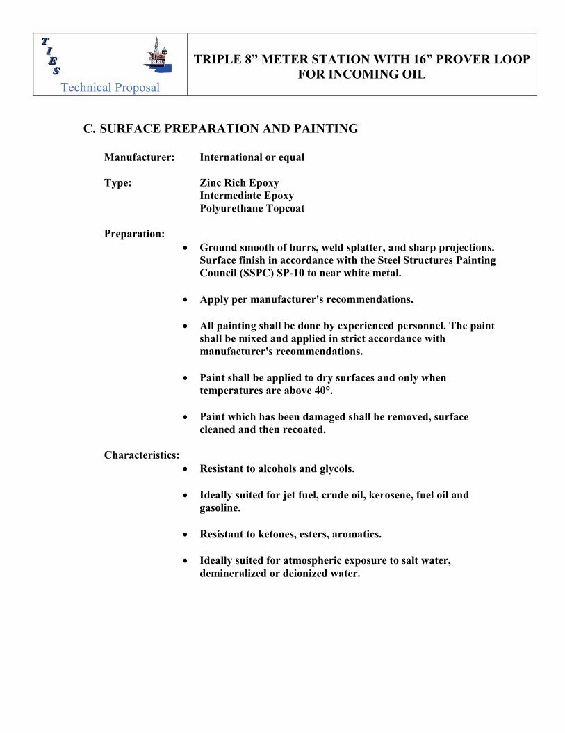
C. SURFACE PREPARATION AND PAINTING
Manufacturer: International or equal Type: Zinc Rich Epoxy
Intermediate Epoxy Polyurethane Topcoat
Preparation:
• Ground smooth of burrs, weld splatter, and sharp projections. Surface finish in accordance with the Steel Structures Painting Council (SSPC) SP-10 to near white metal.
• Apply per manufacturer's recommendations.
• All painting shall be done by experienced personnel. The paint shall be mixed and applied in strict accordance with manufacturer's recommendations.
• Paint shall be applied to dry surfaces and only when temperatures are above 40°.
• Paint which has been damaged shall be removed, surface
cleaned and then recoated.
Characteristics: • Resistant to alcohols and glycols.
• Ideally suited for jet fuel, crude oil, kerosene, fuel oil and
gasoline.
• Resistant to ketones, esters, aromatics.
• Ideally suited for atmospheric exposure to salt water, demineralized or deionized water.

Technical Proposal
TRIPLE 8” METER STATION WITH 16” PROVER LOOP
FOR INCOMING OIL
D. SKID WIRING
All skid electrical materials will have either UL Listed or IEC approval or will have written acceptance. All equipment will be installed per the requirements of International Electric Code, latest edition for Class 1, Zone 2, Gas Group IIA, T3 hazardous locations or per NEC. All on skid electrical wiring will utilize MC/HL cable and cable gland seals routed in stainless steel or aluminum cable trays. Cable Trays:
• Will be stainless steel or aluminum cable tray rigidly supported to skid deck at necessary intervals.
• Factory fittings will be used when practical. Where space prohibits the use of factory fittings, tray will be field fitted as necessary.
Boxes: • Three (3) junction boxes separated for AC power, signal, and
control. • Each Junction Box has 20% spare terminals and entries. • Junction Box hardware and back panels will be Ex’e’, 316 stainless
steel. • Junction Boxes will be mounted at skid edge for easy field wiring
connection and for service access. Wiring:
• All wiring to be via appropriately sized fire retardant, armored cable.
• Cable Glands are nickel plated brass and rated for the service. • Shields shall be grounded on the panel end only. • Each wire or pair will be labeled at both ends. • Each cable will be labeled at both ends. • Circuit breaker disconnects for skid electrical devices are not
included in the scope of this proposal. Name Plates:
• Laminated Phenolic, or equal, nameplates will be provided on each skid junction box white with black fill.
• Nameplates will be fastened with stainless steel screws. Bonding:
• All electrical equipment will be electrically bonded to the skid.

Technical Proposal
TRIPLE 8” METER STATION WITH 16” PROVER LOOP
FOR INCOMING OIL
E. INSPECTION AND TESTING
Flow Laboratory
Component Testing Meters The Meters will be hydrostatically proof tested at the factory to insure there is no leakage. The Meters will be individually flow tested and checked for repeatability and linearity over five (5) points between minimum and maximum meter flow rate at the meter manufacturers facility. Strainers Strainers will be hydrostatically proof tested at the factory to insure there is no leakage. Valves Valves will be tested per manufactures' and applicable API standards. Instrumentation All Pressure and Temperature instruments are checked for proper calibration and performance. System Testing System Hydrostatic Test The complete meter system will be hydrostatically tested to 1.25 times the maximum design pressure for a period of four (4) hours in accordance with specifications
Technical Proposal
TRIPLE 8” METER STATION WITH 16” PROVER LOOP
FOR INCOMING OIL
Skid Electrical Test A continuity check of all wiring and terminations will be made for all electrical items within the skid module. Control System Functional Test All functions of the control system will be tested using simulated inputs. System Visual Inspection All materials will be visually inspected in accordance with the requirements of ASME B31.3. This inspection will include a check for physical damage, both before and after fabrication. System Non-Destructive Testing Systems hydrostatic tests are chart recorded for temperature and pressure. A copy furnished upon request. 10% examination of the total number of circumferential welds 2" and larger; 100% Radiographic examination of each selected weld shall be performed in accordance with ASME Code Section 5, Article 2, Latest Edition; Interpretation of the radiographs to be in accordance with ASME B31.3 All non-pressure bearing welds shall be visually examined except for the lifting lug attachment welds, which shall be examined by magnetic particle or dye penetrant to AWS D1.1 interpretation Vendor Surveillance Sub-vendor inspections of critical items (valves, pipe, etc.) are performed when stipulated by our customer and/or required by TIES's Quality Assurance System. Suppliers of critical items are approved by TIES’s Quality Assurance and stipulated on an approved vendor list, maintained by Quality Assurance.

Technical Proposal
TRIPLE 8” METER STATION WITH 16” PROVER LOOP
FOR INCOMING OIL
VII. DRAWING DELIVERABLES The following documents and drawings will be submitted on TIES standard document formats for “Approval” within date specified from acknowledgement and acceptance of purchase order.
ACRONYM LEGEND
ARO AFTER RECEIPT OF ORDER
ARA AFTER RECEIPT OF CUSTOMER APPROVED DRAWINGS
AC AFTER CONSTRUCTION DRAWINGS
PD PRIOR TO DELIVERY
AD AFTER DELIVERY
DESCRIPTION
ISSUE DATE
PROJECT SCHEDULE 1 – 2 WEEKS ARO
P&ID 1 – 2 WEEKS ARO
GENERAL ARRANGEMENT 1 – 2 WEEKS ARO
PIPING DETAIL DRAWINGS 2 – 3 WEEKS ARA
STRUCTURAL DETAIL 2 – 3 WEEKS ARA
CONTROL PANEL CUTOUT & ASSEMBLY DRAWINGS 4 – 6 WEEKS ARA
JUNCTION BOX LAYOUT & CABLE ENTRY DRAWINGS 4 – 6 WEEKS ARA
SKID AC POWER DISTRIBUTION 4 – 6 WEEKS ARA
METER STREAM & PROVER WIRING DIAGRAMS 4 – 6 WEEKS ARA
CABLE SCHEDULE 4 – 6 WEEKS ARA
LOADING & LIFTING DETAIL DRAWINGS 6 – 8 WEEKS ARA

Technical Proposal
TRIPLE 8” METER STATION WITH 16” PROVER LOOP
FOR INCOMING OIL
Throughout the remainder of the project, the following documents will be submitted based on the sequential order of events with regard to the fabrication, testing, inspection and testing required for the scope of the project.
DESCRIPTION
ISSUE DATE
WELDING PROCEDURES & WELDER QUALIFICATION RECORDS 2 WEEKS AC
NON-DESTRUCTIVE TEST PROCEDURE / NDE PERSONNEL QUALIFICATIONS
2 WEEKS AC
BLASTING AND PAINTING PROCEDURE 4 – 6 WEEKS AC
HYDROSTATIC TEST PROCEDURE 4 – 6 WEEKS AC
FACTORY ACCEPTANCE TEST PROCEDURE 4 – 6 WEEKS AC
RECOMMENDED SPARE PARTS FOR 2-YEAR OPERATION AND COMMISSIONING
8 WEEKS AC
INSTRUMENT/EQUIPMENT CALIBRATION CERTIFICATES 8 WEEKS AC
PACKING LIST 1 WEEK PD
MANUFACTURING DATA RECORD BOOK 4 WEEKS AD
INSTALLATION/OPERATION AND MAINTENANCE MANUAL 4 WEEKS AD
Technical Proposal
TRIPLE 8” METER STATION WITH 16” PROVER LOOP
FOR INCOMING OIL
VIII. ENGINEERING / TECHNICIAN SERVICES The current scale of charges and conditions for this work is as follows, and will remain valid until 31/06/2019, unless otherwise notified. ** Please note that security arrangements need to be provided (by customer) for our site engineers AND TECHNICIANS during any services. All costs relating to these arrangements to be borne by the customer. TIES would review these security arrangements prior to the visit to ensure it meets our company security requirements and in line with US Foreign Office travel advisories.
DATE: - AREA: -
TIES can provide the services of qualified site Engineers or Technicians to perform various tasks related to this system, which include:
-Supervision of initial installation and/or start-up of the complete system; -Planned maintenance visits -Site Commissioning -Problem solving/breakdown cover -Installation of Equipment -Terminations
-Training of operations & maintenance personnel whether on-site or in-house, etc. If these services are required, the following charges will apply: ENGINEER: Normal Rate: PER COMMERICAL BID COST TECHNICIAN: Normal Rate: PER COMMERICAL BID COST Expenses charged at cost will include: Travel (airline, automobile rental, etc.); accommodations and subsistence.
Normal Day rate applies to: 1. All time on site is defined as when our representative is on site available for
work. 2. Standby, captive time (including weekends), is defined as time at the clients
location awaiting local transportation to site, instruction, assistance, tolls or materials.
3. Training and safety induction courses, etc.
Technical Proposal
TRIPLE 8” METER STATION WITH 16” PROVER LOOP
FOR INCOMING OIL
Overtime applies to: 1. Site hours in excess of 12HR per day. General Notes: 1. Travel time is deemed to commence at departure from our offices, and end at
arrival at site or accommodation, and vice versa for the return. 2. Air travel will be at Business Class. If flight is longer than 4 hours a rest day is
provided. 3. All Offshore work would require insurance, which may attract a one off
additional charge. 4. Cancellation with less than 72 hours notice will be charged at 30% of the
scheduled time up to a max of 7 days, plus any direct costs incurred, e.g. flight bookings.
5. Booking - All scheduling will be tentative until purchase order or contract has been received and payment approved. On acceptance of these, travel arrangements will be confirmed.
6. Local Taxes and Duty are not included and will be charged at the prevailing rate.
7. All materials used will be charged at current list price.

Technical Proposal
TRIPLE 8” METER STATION WITH 16” PROVER LOOP
FOR INCOMING OIL
IX. VALIDITY Our tender is open for acceptance for a period of 30 days from the date shown on the title page. We reserve the right to adjust prices in relations to any changes in currency exchange rate or due to fluctuating raw materials prices, which directly affect the cost to us of any bought out goods. These costs would be advised prior to order placement; therefore, quoted price and delivery should be confirmed.
X. WARRANTY We will warranty all manufacture defects in the equipment that we provide for SIX (6) MONTHS upon receipt of equipment. Labor and transportation to our customer to troubleshoot the failed equipment is not included in the warranty.
XI. MAINTENANCE AND SERVICES SUPPORT We would undertake to provide telephone and remote access support in the configuration and troubleshooting of our equipment for the period of the warranty, provided that the initial configuration has been set up by our trained service Engineers / Technician. We would strongly recommend provision of a support contract that would provide access to the wealth of knowledge and enhanced solutions to technical and software issues that we continuously accumulate. If further support is required, a support contract can be provided at that time. We can also provide services to our customer to troubleshoot the equipment at our normal rate as per commercial cost for Engineers or Technicians.