tiller owners manual l1004049
TRANSCRIPT
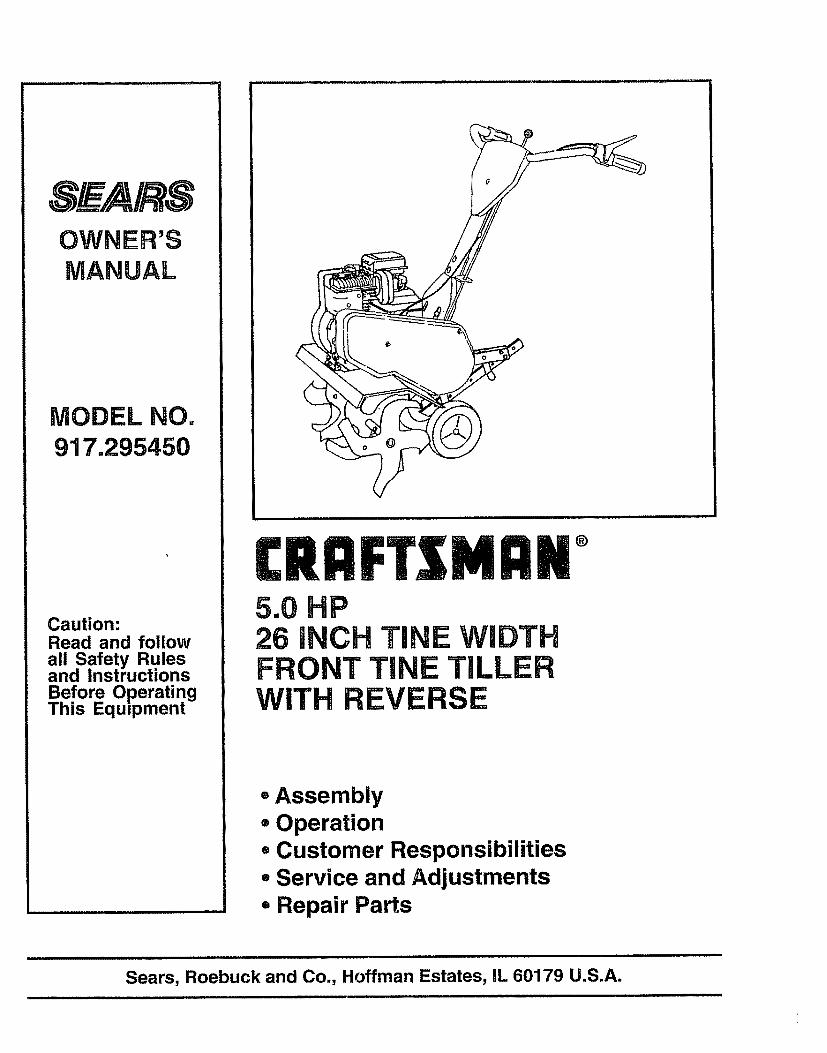
MODEL NO.917.295450
Caution:Read and followall Safety Rulesand InstructionsBefore OperatingThis Eqmpment
MDM °5.0 HP26 H TiNE WIDTHFRONTTi E TILLERWITH E
=Assembly=Operation= Customer Responsibilities° Service and Adjustments° Repair Parts
i
Sears, Roebuck and Co., Hoffman Estates, IL 60179 U.S.A.
SAFETY RULESSafe Operation Practices for Walk-Behind Powered Rotary Tillers
TRAINING
• Read the Owner's Manual carefully° Be thoroughlyfamiliar with the controls and the proper use of theequipment. Know how to stopthe unit and disengagethe controls quickly_
• Never allow childrento operate the equipment. Neverallow adults to operate the equipment withoutproperinstruction..
° Keep the area of operation clear of all persons, particu-larly small children, and pets.
PREPARATION
• Thoroughly inspect the area where the equipment istobe used and remove all foreign objects.
• Disengage all clutches and shift into neutral beforestarting the engine (motor).
° Do not operate the equipment without wearing ad-equate outer garments. Wear footwear that will im-prove footing on slippery surfaces_
° Handle fuel with care; it is highly flammable_° Use an approved fuel container.° Never add fuel to a running engine or hot engine.• Fill fuel tank outdoors with extreme care_ Never fill
fuel tank indoors..
• Replace gasoline cap securely and clean up spilledfue! before restarting.
° Use extension cords and receptacles as specified bythe manufacturer for alt units with electric ddve motorsor electric starting motors..
• Never attempt to make any adjustments while theengine (motor) is running (except where specificallyrecommended by manufacturer)°
OPERATION
• Do not put hands or feet near or under rotating parts..° Exercise extreme caution when operating on or cross-
ing gravel drives, walks, or roads. Stay alert for hiddenhazards or traffic.. Do not carry passengers°
° After striking a foreign object, stop the engine (motor);remove the wire from the spark plug, thoroughly in-spect the tiller for any damage, and repair' the damagebefore restarting and operating the tiller'.
• Exercise caution to avoid slipping or falling,
• If the unit should start to vibrate abnormally, stop theengine (motor) and check immediately for the cause..Vibration is generally a warning of trouble.
• Stop the engine (motor) when leaving the operatingposition.
° Take all possible precautions when leaving the ma-chine unattended. Disengage the tines, shift intoneutral, and stop the engine.
• Before cleaning, repairing, or inspecting,shut off theengine and make certain all moving partshave stopped..Disconnect the spark plug wire, and keep the wireaway from the plug to prevent accidental starting°Disconnect the cord on electric motors°
• Do not run the engine indoors; exhaust fumes aredangerous.
• Never operate the tiller without proper guards, plates,or other safety protective devices in place,.
• Keep children and pets away.• Do not overload the machine capacity by attempting to
till too deep at too fast a rate°° Never operate the machine at high speeds on slippery
surfaces_ Look behind and use care when backing.° Never allow bystanders near the unit.,• Use only attachments and accessories approved by
the manufacturer' of the tiller (such as wheel weights,counterweights, cabs, and the like).
° Never operate the tillerwithout good visibilityor lighL° Be careful when tilling in hard ground.. The tines may
catch in the ground and propel the tiller' forward. If thisoccurs, let go of the handlebars and do not restrain themachine,,
MAINTENANCE AND STORAGE° Keep machine, attachments, and accessories in safe
working condition• Check shear pins, engine mounting bolts, and other
bolts at frequent intervals for proper tightness to besure the equipment is in safe working condition.
• Neverstore the machine with fuel inthe fuel tank insidea building where ignitionsources are present, such ashot water and space heaters, clothes dryers, and thelike. Allow the engine to cool before storing in anyenclosure.,
• Always refer to the operator's guide instructions forimportant details if the tiller is to be stored for anextended period.
- IMPORTANT-CAUTIONS, IMPORTANTS, AND NOTES ARE A MEANS OF ATTRACTING ATTENTION TO IMPORTANT OR CRITICALINFORMATION 1NTHIS MANUAL
A CAUTION: Look for this symbol to pointout important safety precautions. Itmeans ---Attention! Become Alert! Yoursafety is involved.
IMPORTANT: USED TO ALERT YOU THAT THERE IS APOSSIBILITY OF DAMAGING THIS EQUIPMENT.
NOTE: Gives essential information that will aid you to betterunderstand, incorporate, or execute a particular set of instruc-tions,.
2
CONGRATULATIONS on your purchase of a Sears Tiller°It has been designed, engineered and manufactured togive you the best possible dependability and performance.,
Should you experience any problems you cannot easilyremedy, please contact your nearest authorized SearsService Center/Department.. We have competent, welt-trained technicians and the proper tools to service or repairthis unit..
Please read and retain this manual° The instructions willenable you to assemble and maintain your tiller properly.Always observe the "SAFETY RULES'L
MODELNUMBER 917.295450
SERIALNUMBER
DATE OFPURCHASE
THE MODEL AND SERIAL NUMBERS WILL BEFOUND ON THE MODEL PLATE ATTACHED TOTHE RIGHT HAND ENGINE BRACKET°
YOU SHOULD RECORD BOTH SERIAL NUMBERAND DATE OF PURCHASE AND KEEP IN A SAFEPLACE FOR FUTURE REFERENCE°
PRODUCT SPECIFICATIONS
HORSEPOWER: &0 HP
DISPLACEMENT: 12o57cu, in..
GASOLINECAPACITY: 3 QuartsUnleaded Regular
OIL (API-SF/SG): SAE30 (Above 32°F)(CAPACITY:20oz.) SAE5W_30(Below 32°F)
SPARK PLUG : ChampionRJ19LM(GAP: ,030") (STD361458)
MAINTENANCE AGREEMENT
A Sears Maintenance Agreement is available on thisprod-uct, Contact your nearest Sears store for details.
CUSTOMER RESPONSIBILITIES
o Read and observe the safety rules,.• Followa regular schedule in maintaining, caring for and
using your tiller,• Follow the instructions under the "Customer
Responsibilities" and "Storage" sections of this Owner'sManual
IMPORTANT: THIS UNIT IS EQUIPPED WITH AN INTERNAL COMBUSTION ENGINE AND SHOULD NOT BE USED ONOR NEAR ANY UNIMPROVED FOREST-COVERED, BRUSH-COVERED OR GRASS COVERED LAND UNI.ESS THEENGINE'S EXHAUST SYSTEM IS EQUIPPED WITH A SPARK ARRESTER MEETING APPLICABLE LOCAL OR STATELAWS (IF ANY).. IF A SPARK ARRESTER IS USED, IT SHOULD BE MAINTAINED IN EFFECTIVE WORKING ORDER BYTHE OPERATOR..
IN THE STATE OF CALIFORNIA THE ABOVE tS REQUIRED BY LAW (SECTION 4442 OF THE CALIFORNIA PUBLICRESOURCES CODE). OTHER STATES MAY HAVE SIMILAR LAWS. FEDERAL LAWS APPLY ON FEDERAL LANDS.SEE YOUR SEARS AUTHORIZED SERVICE CENTER FOR SPARK ARRESTER. REFER TO THE REPAIR PARTSSECTION OF THIS MANUAL FOR PART NUMBER.
LIMITED TWO YEAR WARRANTY ON CRAFTSMAN TILLERFor two (2) years from date of purchase, when this Craftsman Tiller is maintained, lubricated, and tuned upaccording to the operating and maintenance instructions in the owner's manual, Sears will repair free of charge anydefect in matedal or workmanship°
This Warranty does not cover:
° Expendable items which become worn during normal use, such as tines, spark plugs, air cleaners and belts.
- Repairs necessary because of operator abuse or negligence, including bent crankshafts and the failure tomaintain the equipment according to the instructions contained in the owner's manual°
° if this Craftsman Tiller is used for commercial or rental purposes, this Warranty applies for only thirty (30) daysfrom the date of purchase.
WARRANTY SERVICE IS AVAILABLE BY RETURNING THE CRAFTSMAN TILLER TO THE NEAREST SEARSSERVICE CENTER/DEPARTMENT IN THE UNITED STATES. THIS WARRANTY APPLIES ONLY WHILE THISPRODUCT IS IN USE IN THE UNITED STATES..
This Warranty gives you specific legal rights, and you may also have other rights which vary from state to staten
SEARS, ROEBUCK AND CO., D/817WA, HOFFMAN ESTATES, IL 60179
3

............................................. . i
TABLE OF CONTENTS
SAFETY RULES ........................................................... 2
CUSTOMER RESPONSIBIUTIES ..................... 3, 12-14PRODUCT SPECIFICATIONS ...................................... 3WARRANTY .................................................................. 3ACCESSORIES ............................................................. 5ASSEMBLY ............................................................... 6-7OPERATION ............................................................ 8-11
MAINTENANCE SCHEDULE ..................................... 12SERVICE & ADJUSTMENTS ................................ 14-17STORAGE ................................................................... 18TROUBLESHOOTING ................................................. 19REPAIR PARTS-TILLER ....................................... 20-25REPAIR PARTS-ENGINE ...................................... 26-30SERVICEJPARTS ORDERING .................... Back Cover
INDEXA
Accessories ......................................................5Adjustments:
Carburetor .............................................17Depth Stake .......................................9Handle Height .............................14Tines .................................................14-15V-Belt ..............................................16Wheels ..............................................9
Air Cleaner ...................................... 13
BBelt, V<
Belt Guard ..........................................17Repair Parts .....................................21V-Belt Replacement ......................16
CCoo}ing System ..........................................13Controls:
Choke ...........................................8Throttle ..............................................8Tines ................................................8
Cultivating .....................................................11Customer Responsibilities:
Air Cleaner .........................................13Cooling System ...........................13Finish ............................................14Maintenance Schedule ................12Muffler. ...............................................14Oil Change ....................................13Spark Plug ..............................................14Transmission ..............................14
DDepth Stake:
Adjustment ......................................9Repair Parts ................................22
EEngine:
Air Cleaner ........................................t3Cooling System ................................13Fuel Type ........................................10Lubrication ................................. i3Oil Level .......................................i0
Oil Type ......................................10,13Repair Parts ..........................26-30Spark Plug .....................................14Starting ................................................10Stopping ..........................................................9Storage ..................................................18Winter Operation ..............................13
FFuel:
Filling Tank ........................................t0Storage ..........................................18Type ...................................................10
Finish:Maintenance ........................................14
HHandle:
Height Adjustment ...........................14Repair Parts ......................................20
LLubrication:
Lubrication Chart .........................12Engine ...............................................13
MMuffler:
Maintenance .................................14Spark Arrester. ...............................3
OOil:
Level ................................................10Type ..............................................10,13
Operation:Cultivating ......................................11Fill Fuel Tank ............................ 10Starting Engine ........................ 10Stopping Tines & Engine .......... 9Tilling .....................................................9Tilling Hints .........................................11Tine Operation ........................................9Transporting Tiller. .......................t0Winter Operation .............i.............13
RRepair Parts
Tit{er ...........................................................20-24Engine ..........................................26-30
Rules for Safe Operation ........................2
SService & Adjustments:
Carburetor .....................................17Handle Height .............................14Tines .......................................14-15V-Belt .............................................16Wheels ...................................................... 9
Service:Repair Parts ...........................20-30Service Record ...........................12
Spark Plug:Gap .....................................................3Maintenance .................................14
Storage:Fuel System ................................18Tiller .............................................................18
TTilling .......................................................9,11Tines:
Arrangement ................................14-15Operation ...............................................9Repair Parts ...............................23Replacement .......................................15
Transmission:Maintenance ................................14Repair' Parts ................................24
Troubleshooting .......................................19Transporting .......................................I0
WWarranty ............................................................3Wheels:
Adjustments ....................................9Repair Parts ..................................22
4
ACC Rm
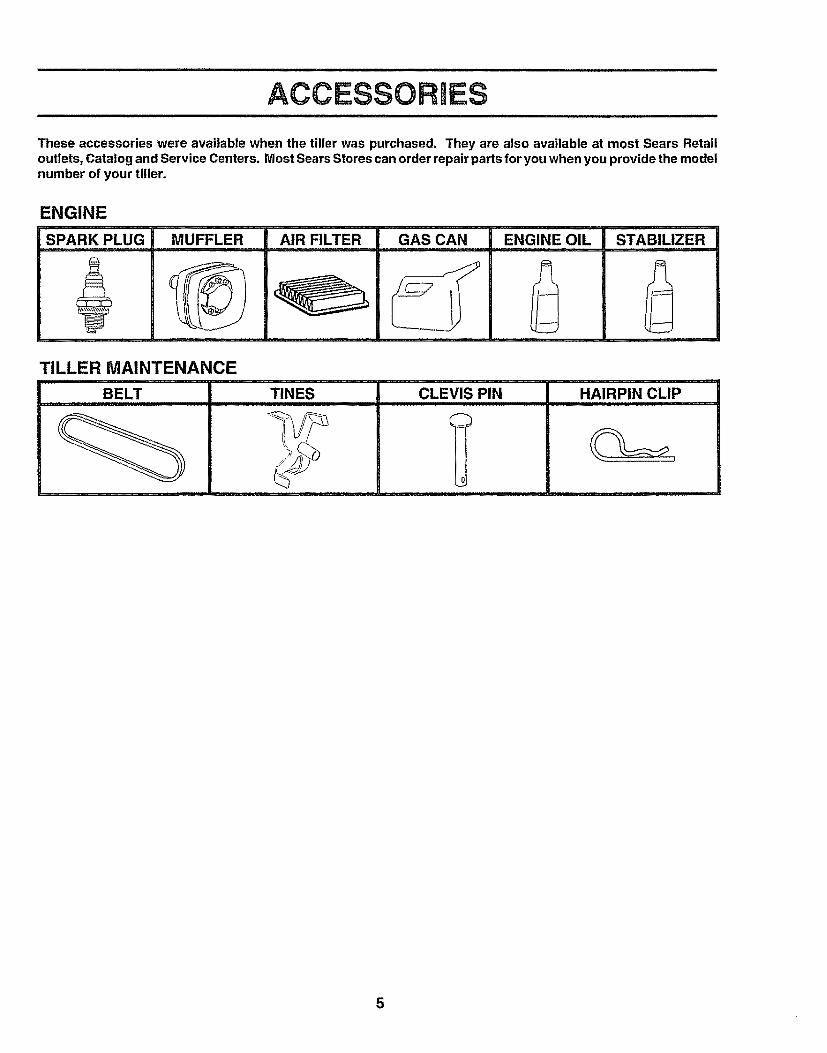
These accessories were available when the tiller was purchased. They are also available at most Sears Retailoutlets, Catalog and Service Centers. Most Sears Stores can order repair parts for you when you provide the modelnumber of your tiller.
ENGINE
SPARK rpLUG MUFFLER
_L
AIR FILTER GAS CAN
TILLER MAINTENANCE
BELT TINES CLEVIS PIN
0
HAIRPIN CLIP
5
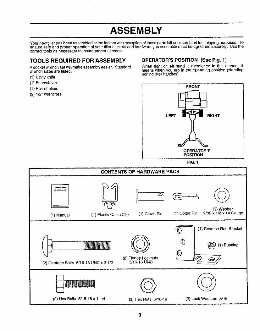
MBLYYour new tiller has been assembled at the factory with exception of those parts left unassembled for' shipping purposes, Toensure safe and proper operation of your tiller' all partsand hardware you assemble must be tightened securely. Use thecorrect tools as necessary to insure proper tightness°
TOOLS REQUIRED FOR ASSEMBLYA socket wrench set will make assembly easier,, Standardwrench sizes are listed.
(1) Utility knife
(1) Screwdriver
(I) Pair of pliers(2) 1/2" wrenches
OPERATOR'S POSITION (See Fig. 1)When right or left hand is mentioned in this manual, itmeans when you are in the operating position (standingbehind tiller handles),
FRONT
LEFT RIGHT
OPERATOR'SPOSITION
FIG. 1................ , ,, ,,, ,, ,,,,,,,,,,,,,,..,,,...,,
CONTENTS OF HARDWARE PACKI J I I II I lUUlIIIlUlIIII
........... lllj
I J L L II
(1) Manual (1) Plastic Cable Clip (1) Clevis Pin(1) Washer
(1) Cotter Pin 9/32 x 1/2 x 14 Gauge
(2) Carriage Bolts 5/16-t8 UNC x 2-1/2
(2) Hex Bolts 5/16-18 x 1-1/4, ,, ,,,,,,,,,,,,,,,,,,,,,,,,
Q(2) Flange Locknuts
5/16-18 UNC
Q(2) Hex Nuts 5/t6-18
)
©0 I
(1) Reverse Rod Bracket
(_(1) Bushing
(2) Lock Washers 5/16
6
LYUNPACK CARTON
i CAUTION: Be careful Of exposed astaples when handling or disposing of !Acartoning materia I, !
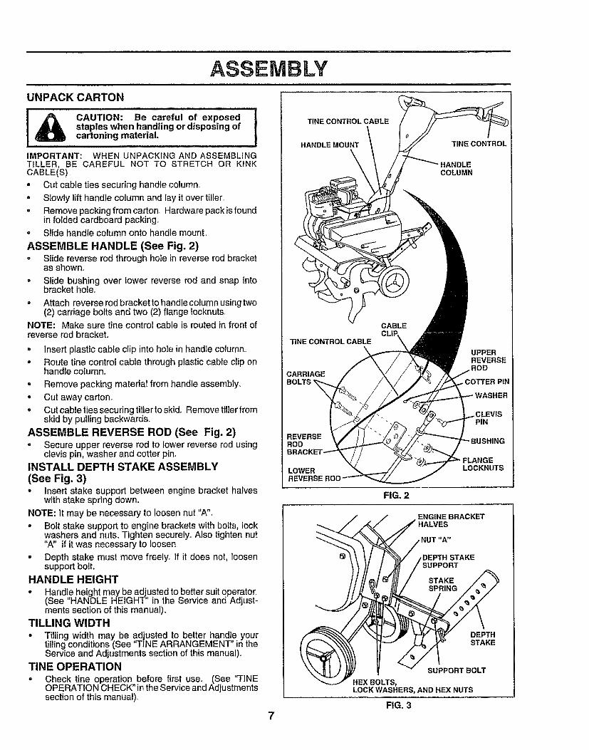
IMPORTANT: WHEN UNPACKING AND ASSEMBLINGTILLER, BE CAREFUL NOT TO STRETCH OR KiNKCABLE(S)= Cut cable ties securing handle column.
= Slowly lift handle column and lay it over tiller+° Remove packing from carton+,Hardware pack isfound
in folded cardboard packing.o Slide handle column onto handle mount,
ASSEMBLE HANDLE (See Fig. 2)o Slide reverse rod through hole in reverse rod bracket
as shown.
° Slide bushing over lower reverse rod and snap intobracket hole,+
• Attach reverse rod bracket to handle column using two(2) carriage bolts and two (2) flange tocknuts,,
NOTE: Make sure tine control cable is routed in front ofreverse rod bracket+
= Insert plastic cable clip into hole in handle column.,
o Route tine control cable through plastic cable clip onhandle column.
o Remove packing matedal from handle assembly+
° Cut away carton.
= Cut cable ties securing tiller to skid+ Remove tiller fromskid by pulling backwards+
ASSEMBLE REVERSE ROD (See Fig, 2)o Secure upper reverse rod to lower reverse rod using
clevis pin, washer and cotter pin+INSTALL DEPTH STAKE ASSEMBLY
(See Fig. 3)• insert stake support between engine bracket halves
with stake spring down+,
NOTE: It may be necessary to loosen nut "A",• Bolt stake support to engine brackets with botts, lock
washers and nuts. Tighten securely+ Also tighten nut"A" if it was necessary to loosen.
° Depth stake must move freely+ If it does not, toosensupport bolt.
HANDLE HEIGHT
• Handle height may be adjusted to better suit operator.,(See "HANDLE HEIGHT'' in the Service and Adjust-ments section of this manual).
TILLING WIDTH
• T+lling width may be adjusted to better handle yourtilling conditions (See "TINE ARRANGEMENT" in theService and Adjustments section of this manual)°
TINE OPERATION= Check tine operation before first use+, (See "FINE
OPERATION CHECK" in the Service and Adjustmentssection of this manual),,
TfNE CONTROL CABLE
HANDLE MOUNT TfNE CONTROL
COLUMN
TtNECONTROLCABLE\
CARRIAGEBOLTS
REVERSERODE
LOWER
CABLECLII:
UPPERREVERSE
ROD
WASHER
PIN
LOCKNUTS
FIG. 2
ENGINE BRACKETHALVES
STAKESUPPORT
DEPTHSTAKE
SUPPORT BOLT
HEX BOLTS,LOCK WASHERS, AND HEX NUTS
FIG. 3
7
OPERATION
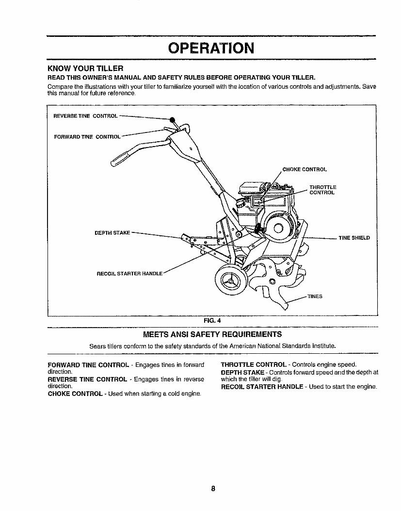
KNOW YOUR TILLERREAD THIS OWNER'S MANUAL AND SAFETY RULES BEFORE OPERATING YOUR TILLER.
Compare the illustrationswith your tiller to familiarize yourselfwith the location of variouscontrols and adjustments, Savethis manual for' future reference.
REVERSE "ftNE CONTRO!.
FORWARD TINE CONTROL
CHOKECONTROL
THROTTLECONTROL
DEPTH STAKETINE SHIELD
RECOIL STARTER HANDLE
FIG. 4
MEETS ANSI SAFETY REQUIREMENTS
Sears tillers conform to the safety standards of the American National Standards Institute,.
FORWARD TINE CONTROL - Engages tines in forwarddirection,
REVERSE TINE CONTROL - Engages tines in reversedirection,
CHOKE CONTROL - Used when starting a cold engine,.
THROTTLE CONTROL - Controls engine speed.DEPTH STAKE - Controls forward speed and the depth atwhich the tiller' will dig_RECOIL STARTER HANDLE - Used to start the engine,
8
OPEBATn
The operation of any tiller can result in foreign objects thrown into the eyes, which canresult in severe eye damage. Always wear safety glasses or eye shields before startingyour tiller and while tilling. We recommend a wide vision safety mask over the spectaclesor standard safety glasses.
HOW TO USE YOUR TILLER
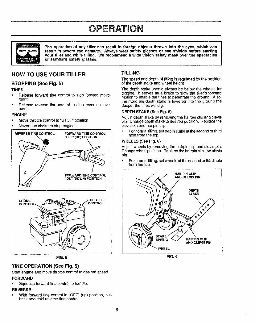
STOPPING (See Fig. 5)TINES
• Release forward tine control to stop forward move-mento
= Release reverse tine control to stop reverse move-mento
ENGINE
. Move throttle controt to "STOP" position,- Never use choke to stop engine.
REVERSE TINE CONTROL FORWARD TINE CONTROL
I " //./ FORWARD TINE CONTROL
/_ "ON" (DOWN) POSITION
CHOKECONTROL_,
FIG. 5
TINE OPERATION (See Fig. 5)Start engine and move throttlecontrol to desired speed..FORWARD
• Squeeze forward tine control to handle,,REVERSE
• With forward tine control in "OFF" (up) position, puttback and hold reverse tine control,,
TILLING
The speed and depth of tilling is regulated by the positionof the depth stake and wheel height.
The depth stake should always be below the wheets fordigging. It serves as a brake to slow the filler's forwardmotion to enable the tines to penetrate the ground. Also,the more the depth stake is lowered into the ground thedeeper the tines will dig.
DEPTH STAKE (See Fig. 6)
Adjust depth stake by removing the hairpin clip and clevispin,, Change depth stake to desired position° Replace theclevis pin and hairpin clip,,° For normal tilling, set depth stake at the second or third
hole from the top.
WHEELS (See Fig. 6)Adjust wheels by removing the hairpin clip and clevis pin°Change wheel position_ Replace the hairpin clip and clevispin_
• For normal tilling, set wheels at the second or third holefrom the top,,
HAIRPIN CLIPAND CLEVIS PIN
DEPTHSTAKE
WHEEL
HAtRPIN CL|PAND CLEVIS PIN
FIG, 6
9
ii
OPERATION
TRANSPORTING YOUR TILLER
CAUTION: Before lifting or transport,-ing, allow tiller engine and muffler tocool. Disconnectsparkplug wire. Draingasoline from fuel tank.
AROUND THE YARD
. Tip depth stake forward until it is held by the stakespdng.
. Push tiller handles down, raising tines off the ground
• Push or pull tiller to desired location°
AROUND TOWN
° Disconnect spark plug wire.• Drain fuet tank_
. Transport in upright position to prevent oil leakage.
BEFORE STARTING ENGINEIMPORTANT: BE VERY CAREFUL NOT TO ALLOWDIRT TO ENTER THE ENGINE WHEN CHECKING ORADDING OILOR FUEL. USE CLEAN OILAND FUELANDSTORE IN APPROVED, CLEAN, COVEREDCONTAINERS. USE CLEAN FILL FUNNELS.
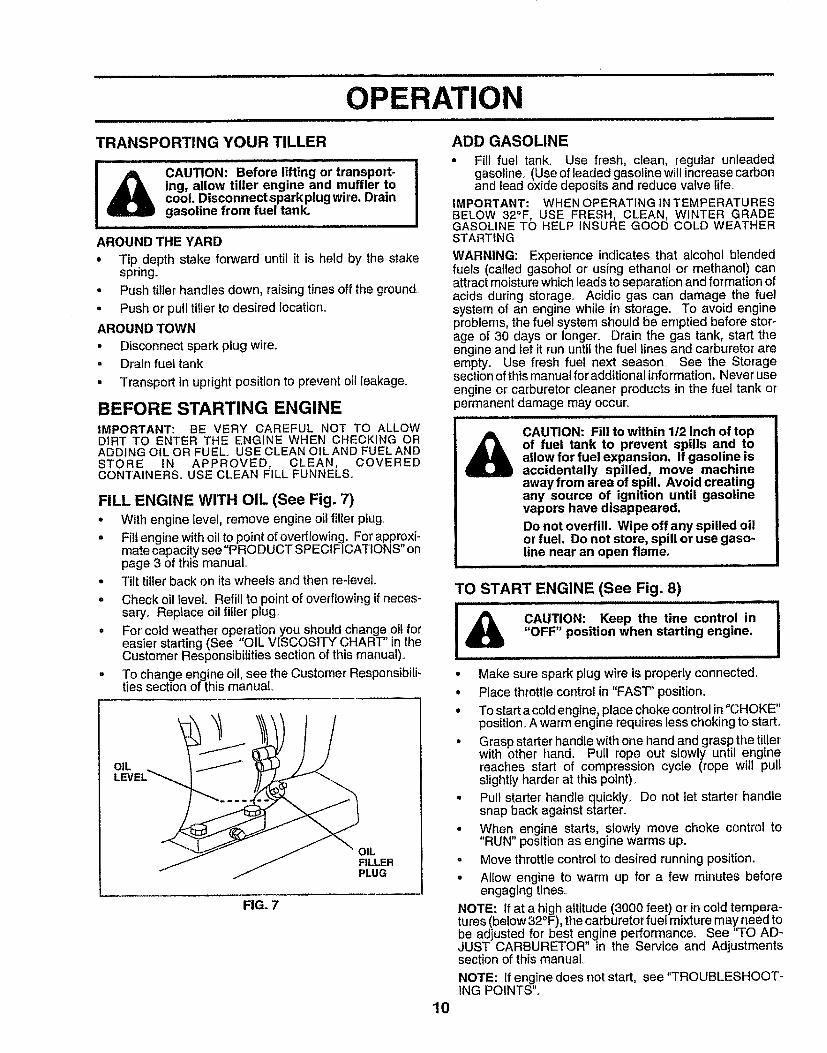
FILL ENGINE WITH OIL (See Fig. 7)• With engine level, remove engine oil filler plug.
° Fillengine withoil to pointof overflowing. For approxi-mate capacitysee "PRODUCT SPECIFICATIONS" onpage 3 of this manual°
• Tilt tillerback on its wheels and then re-leveL
° Check oil level. Refill to pointof overflowingif neces-saryo Replace oil filler plug_
. For cold weather operation you should change oil foreaster starting (See OIL VISCOSITY CHART' JnthCustomer Responsibilitiessection of this manual).
° To change engine oil, see the Customer Responsibili-ties section of thismanual.
OILFILLERPLUG
FIG. 7
ADD GASOLINE
• Fitl fuel tank° Use fresh, c_ean, regular unleadedgasoline_ (Use of leaded gasoline will increase carbonand lead oxide deposits and reduce valve life.
IMPORTANT: WHEN OPERATING IN TEMPERATURESBELOW 32°F, USE FRESH, CLEAN, WINTER GRADEGASOLINE TO HELP INSURE GOOD COLD WEATHERSTARTING
WARNING: Experience indicates that alcohol blendedfuels (called gasohol or using ethanol or methanol) canattract moisture which leads to separation and formation ofacids during storage, Acidic gas can damage the fuelsystem of an engine while in storage. To avoid engineproblems, the fuel system should be emptied before stor-age of 30 days or longer'. Drain the gas tank, start theengine and Iet it run until the fuel lines and carburetor areempty. Use fresh fuel next season. See the Storagesection of this manual for'additional information. Never useengine or carburetor cleaner products in the fuel tank or_ermanent damage may occur,,
A CAUTION: Fill to within 1t2 inch of topof fuel tank to prevent spills and toallow for fuel expansion, If gasoline isaccidentally spilled, move machineaway from area of spill, Avoid creatingany source of ignition until gasolinevapors have disappeared.Do not overfill. Wipe off any spilled oilor fuel. Do not store, spill or use gaso-line near an open flame.
i iiii iii i
TO START ENGINE (See Fig. 8)
CAUTION: Keep the tine control in"OFF" position when starting engine.
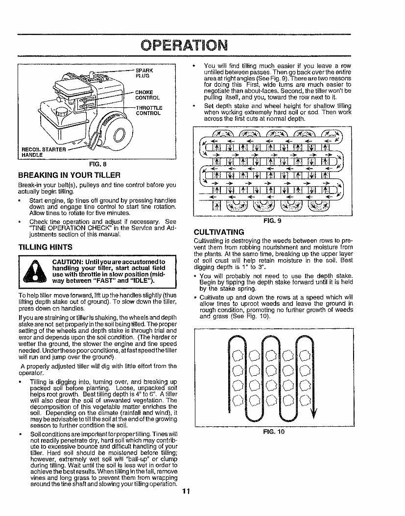
• Make sure spark plug wire is properly connected.
• Place throttle control in "FAST" position,
° To start a coldengine; placechoke controlin "CHOKE"position. A warm engine requires less chokingto start_
• Grasp starter handle with one hand and grasp the tillerwith other hand. Pull rope out slowly until enginereaches start of compression cycle (rope will pultslightly harder at this point)_
° Pull starter handle quickly_ Do not let starter' handlesnap back against starter.
• When engine starts, slowly move choke control to"RUN" positionas engine warms up.
o Move throttlecontrolto desired running position.
= Allow engine to warm up for a few minutes beforeengaging tines.,
NOTE: If at a high altitude (3000 feet) or incold tempera-tures(below 32°F), the carburetor fuel mixture may need tobe adjusted for best engine performance, See 'q'O AD-JUST CARBURETOR" in the Service and Adjustmentssection of this manual
NOTE: If engine does not start, see "TROUBLESHOOT-ING POINTS".
10
OPEBATmON
e
RECOIL STARTER /HANDLE
.---," CHOKECONTROL
THROTTLECONTROL
?FIG. 8
BREAKING IN YOUR TILLER
Break-in your belt(s), pulleys and tine control before youactually begin ti_lingo
o Start engine, tip tines off ground by pressing handlesdown and engage tine control to start tine rotation.Allow tines to rotate for five minutes..
• Check tine operation and adjust if necessary. See'q'tNE OPERATION CHECK" in the Service and Ad-justments section of this manual..
TILLING HINTS
l_ CAUTION: Until you are accustomed to
handling your tiller, start actual fielduse with throttle in slow position (mid-way between "FAST" and "IDLE").
, , ,,,,,,,,,, ,,,,,,, ,
To help tiller move forward, lift up the handles slightly (thuslifting depth stake out of ground). To slow down the tiller,press down on handles.,
Ifyou are straining or tiller is shaking, the wheels and depthstake are not set properly in the soil being tilled..The propersetting of the wheels and depth stake is through trial anderror and depends upon the soil condition,. (The harder orwetter the ground, the slower the engine and tine speedneeded+.Under these poorconditions, at fast speed the tillerwill run and jump over the ground),
A properly adjusted tiller will dig with little effort from theoperator.
° Tilling is digging into, turning over, and breaking uppacked soil before planting° Loose, unpacked soilhelps root growth.. Best tilling depth is 4" to 6". A tillerwill also clear the soiI of unwanted vegetation.+ Thedecomposition of this vegetable matter enriches thesoil+ Depending on the climate (rainfall and wind), itmay be advisable to till the soil at the end of the growingseason to further condition the soil.
Soil conditions are importantfor proper tilling.+Tines willnot readily penetrate dry, hard soil which may contrib +ute to excessive bounce and difficult handling of yourtiller.. Hard soil should be moistened before tilling;however, extremely wet soil will "ball-up" or clumpduring tilling,. Wait until the soil is less wet in order toachieve the best results+When tilling in the fall, removevines and long grass to prevent them from wrappingaround the tine shaft and slowing your tiilingoperation,.
11
You will find tilling much easier if you leave a rowuntilled between passes., Then go back over the entirearea at right angles (See Fig ,.9),,There are two reasonsfor doing this_ First, wide turns are much easier tonegotiate than about-faces,. Second, the tiller won't bepulling itself, and you, toward the row next to iLSet depth stake and wheel height for shallow tillingwhen working extremely hard soil or sod,. Then workacross the first cuts at normal depth+
FIG, 9
CULTIVATINGCultivating is destroyingthe weeds between rows to pre-vent them from robbing nourishment and moisture fromthe plants+At the same time, breaking up the upper layerof soiI crust will help retain moisture in the soil.. Bestdigging depth is 1" to 3".- You witl probably not need to use the depth stake.
Begin by tippingthe depth stake forward until it is heldby the stake spring+
• Cultivate up and down the rows at a speed which willallow tines to uproot weeds and leave the ground inrough condition, promoting no further growth of weedsand grass (See Fig,. t0).
FIG. 10
CUSTOMER RESPONSIBILITIESJl,lll,l,lll ii II I Ill I II IIIIIIHIIIIll Ill I I I I I
MAINTENANCE /
SCHEDULE
FILL IN DATESAS YOU COMPLETE /Z_'-'/_/,REGU_ R SERV ICE / _b""i _"--'/
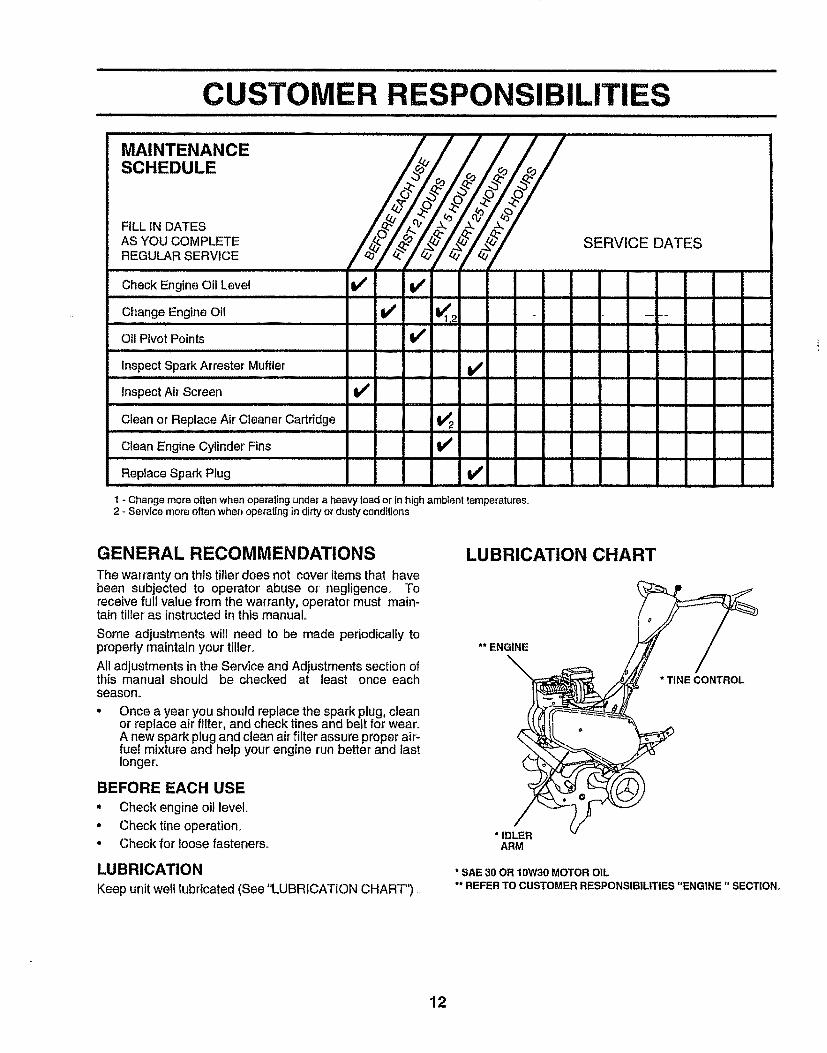
Check Engine Oil Level V' V'
Change Engine Oil I1_
Oil PivotPoints V'
_'_ SERVICE DATES
K2 --'=-
inspect Spark Arrester Muffler V'
Inspect Air Screen V'
Clean or Replace Air Cleaner Cartridge !_ 2
Clean Engine Cylinder Fins,,, .,,,,, _,,
Replace Spark Plug I_ •
1 - Change more often when operating under a heavy load or in high ambient temperatures,2 - Service more often when operating in dirty or dusty conditions
GENERAL RECOMMENDATIONSThe warranty on this tiller does not cover items that havebeen subjected to operator abuse or negligence_ Toreceive full value from the warranty, operator must main-tain tiller as instructed in this manual,
Some adjustments will need to be made periodically toproperly maintain your tiller°
All adjustments in the Service and Adjustments section ofthis manual should be checked at least once eachseasom
Once a year you should replace the spark plug, cleanor replace air filter, and check tines and belt for wear.A new spark plug and clean air filter assure proper air-fue! mixture and help your engine run better and lastIonger_
BEFORE EACH USE
• Check engine oil level.
• Check tine operation,• Check for loose fasteners°
LUBRICATION
Keep unit welt lubricated (See "LUBRICATION CHART")
LUBRICATION CHART
** ENGINE
\
"IDLERARM
* SAE 30 OR 10W30 MOTOR OIL** REFER TO CUSTOMER RESPONSIBILITIES ENGINE SECTION.
12

CUSTOMER RESPONSIBmLUTNES
Disconnect spark plug wire before performingany maintenance(except carburetor adjustment) to prevent Iaccidental startingof engine, iPreventfires! Keepthe enginefree of grass, leaves,spilledoil,or fuel. Removefuel fromtank beforetipping Iunit for maintenance. Clean mufflerarea of all grass, dirt, anddebris. IDo nottouch hotmuffler or cylinderfins as contactmay cause burns, !
....... ,llllllllll llll ill ill1 ii ii ii
ENGINE
LUBRICATION
U_e only high quality detergent oil rated with API serviceclassification SF or SG. Select the oil's SAE viscosity gradeaccording to your expected temperature
SAE VISCOSITY GRADES
_'F _20_ 0 _ 30 ° 32_ 40° 60 _ 80_ t00_
"c -_o, .2'0. .I_, ¥ ..... i'o, _o. _o" 4_"TEMPERATURE RANGE ANT_CIPATED BEFORE NEXT OIL CHANGE
FIG. 1t
NOTE: Although multi-viscosity oils (5W-30,10W-30, etc.)improvestarting in cold weather, these multi-viscosity oilswill result in increased oil consumption when used above32° F (0°C). Check your engine oil level more frequently toavoid possible engine damage from running tow on oil,Change the oil after the first two hours of operation andevery 25 hours thereafter or at least once a year if the tilleris not used for 25 hours in one yearCheck the crankcase oil level before starting the engineand after each five (5) hours of continuous use Add SAE30 motor oil or equivalent. Tighten oil filler plug securelyeach time you check the oil level.
TO CHANGE ENGINE OIL (See Figs. 11 and 12)Determinetemperature range expected before oilchange_.All oil must meet API service classificationSF or SG..
. Be sure tiller is on level surfaceo Oil will drain more freely when warm_• Catch oil in a suitable container.• Remove drain plug.° Tip tiller forward to drain oil. After oil has drained completely, replace oil drain plug
and tighten securely. Remove oil filler plugo Be carefut not to allow dirt to
enter the engine°• Refill engine with oil. See "CHECK ENGINE OIL
LEVEU' in the Operation section of this manual°
OILDRAINPLUG
PLUG
FIG. 12
AIR CLEANER (See Fig. 13)Service air cleaner cartridgeevery twenty-five hours, moreoften if engine is used invery dusty conditions_° Loosenair cleaner screws, one on each side of cover..• Remove air cleaner cover_
° Carefully remove air cleaner cartridge° Be careful. Donot allow dirt or debristo fall into carburetor.
o Clean by tapping gently on a fiat surface°
= If very dirty or damaged, replace cartridge.
• Clean and replace cover_Tighten screws securely°
!_ CAUTION: Petroleum solvents, such
as kerosene, are not to be used to cleancartridge, They may cause deteriora-tion of the cartridge. Do not oil car-tridge, Do not use pressurized air toclean or dry cartridge.
COVER
CLEANERCARTRIDGE
FIG. 13
COOLING SYSTEM (See Fig. 14)Your engine is air cooled For proper engine performanceand long life keep your engine clean°• Clean air screen frequently using a stiff-bristled brush,
- Remove blower housing and clean as necessary,
- Keep cylinder fins free of dirt and chaff.
CYLINDER FINSMUFFLER "_x BLOWER
J HOUSING
AIR SCREEN
)FIG. 14
13
CUSTOMER ILITIJill IIU Ill/,llllUJlll ,,
MU FFLER TRANSMISSION
Do not operate tiller' without muffler° Do not tamper withexhaust system. Damaged mufflers or spark arresterscould create a fire hazard° Inspect periodically and replaceif necessary, If your engine is equipped with a sparkarrester screen assembly, remove every 50 hours forcleaning and inspection. Replace if damaged.
SPARK PLUG
Replace spark plugs at the beginning of each tillingseasonor'after every 50 hours of use, whichevercomes first. Sparkplug type and gap setting is shown in "PRODUCT SPECI-FICATIONS" on page 3 of this manual,,
Your transmission issealed and will only require lubricationif it is serviced.
CLEANING• Clean engine, wheels, finish, etc_.of all foreign matter°• Keep finished surfaces and wheels free of all gasoline,
oil, etc.
• Protect painted surfaces with automotive type wax..
We do not recommend using a garden hose to clean yourunit unless the muffler, air filter and carburetor are coveredto keep water out. Water inengine c_nresult in a shortenedengine life_
SERVICE AND ADJUSTMENTS
CAUTION: Disconnect spark plug wire from spark plug and place wire where it cannot come intocontact with plug.
TILLER
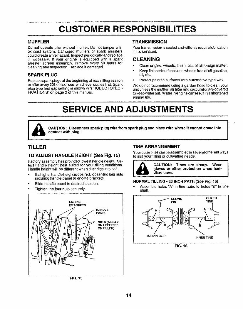
TO ADJUST HANDLE HEIGHT (See Fig. 15)Factory assembly has provided lowest handle height. Se-lect handle height best suited for your tilling conditions.,Handle height will be different when tiller digs into soil..
• Ifa higher handle height isdesired, loosen the four nutssecuring handle panel to engine brackets°
° Slide handle panel to desired Iocation_
° Tighten the four nuts securely.,
TINEARRANGEMENT
Your outer tines can beassembled in several different waysto suit your tilling or cultivating needs_
i_ CAUTION: Tines are sharp. Weargloves or other protection when han-dling tines.
NORMAL TILLING -26 INCH PATH (See Fig. 16)• Assemble holes "A" in tine hubs to holes "B" in tine
shaft.
t
//iid
ENGINEBRACKETS
HANDLEPANEL
NUTS (ALSO 2ON LEFT SIDEOF TILLER)
HAIRPIN CLIP INNER TtNE
FIG. 16
FIG. 15
14
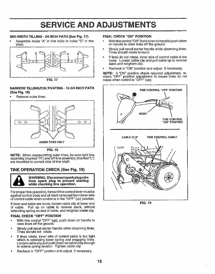
MID-WIDTH TILLING - 24 INCH PATH (See Fig. 17), Assemble holes "A" in tine hubs to holes "C" in tine
shaft.
FIG. 17
FINAL CHECK "ON" POSITION
= Withtinecontrol"ON"(held down tohandle) push downon handte to raise tines off the ground.
• Slowly pull recoil starter handle while observingtines,Tines should rotate forward,
- If tines do not rotate, inner wire of control cable is tooloose,. Loosen cable clip and pullcable up to removeslack and retighten clip..
• Recheck in "ON" position and adjust if necessary..
NOTE:, If "ON" position check required adjustment, re-check OFF position adjustment to insure tines do notrotate when control is "OFF" (up).
NARROW TILLINGtCULTIVATING - 12-314 INCH PATH(See Fig, 18)° Remove outer tines°
o o/'-'1 t
Oll II©i © ©
INNER TINES ONLY
FIG. 18
NOTE: When reassembting outer tines, be sure right tineassembIy (marked "R") and left tine assembly (marked "L")are mounted to correct side of tine shaft..
TINE OPERATION CHECK (See Fig. '19)
...............ii& WARNING: Disconnectsparkplugwirefrom spark plug to prevent startingwhile checking tine operation,
For proper tine operation, forward tine control lever must beagainst control body and all stack removed from inner wireof control cable when control is in the "OFF" (up) position.
If lever and cable are loose, loosen cabte clip at tower endof cable° Pull up on cable to remove slack, withoutextending spring on end of cable, and retighten cable clipoFINAL CHECK "OFF" POSITION
° With tine control "OFF" (up), push down on handle toraise tines off the ground.
o Slowly pull recoil starter handle while observing tines_Tines should not rotate.
• If tines rotate, inner wire of control cable is too tightwhich is extending lower spring and engaging tines.Loosen cable clip and push clownon cable only enoughto relieve spring tension_ Tighten cable clipo
° Recheck in "OFF" position and adjust if necessary..
TINE CONTROL "OFF" POSITION
TINE CONTROL"ON" POSITION
CABLE CLIP TINE CONTROL CABLE
FIG, 19
15
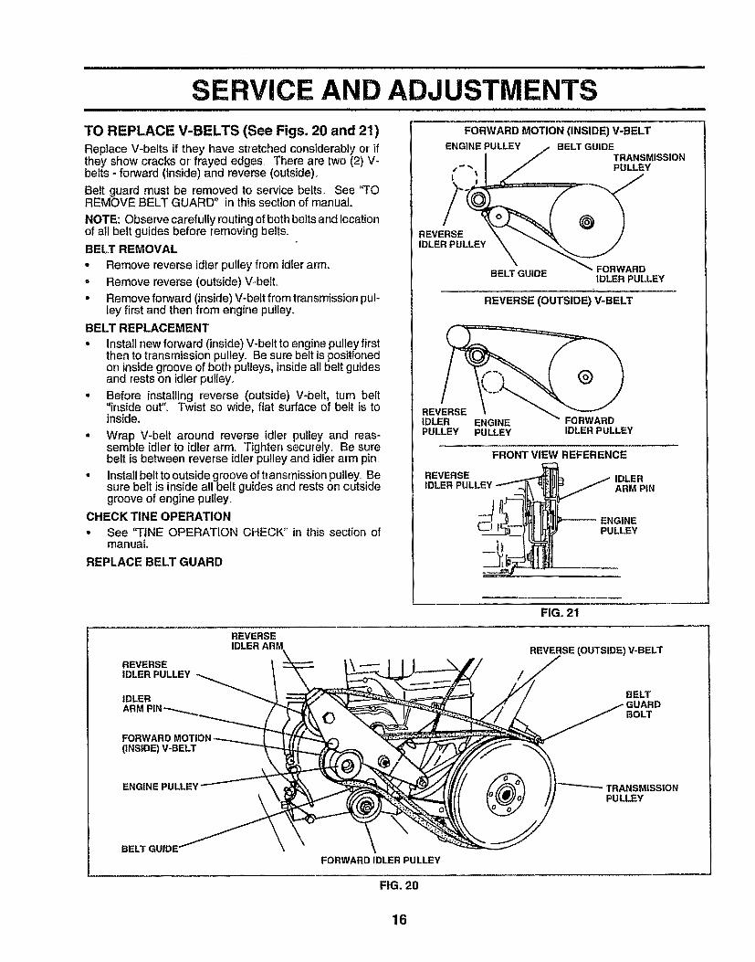
TO REPLACE V-BELTS (SeeFigs. 20and 21)Replace V-belts if they have stretched considerably or ifthey show cracks or frayed edges° There are two (2) V-belts - forward (inside) and reverse (outside)°
Belt guard must be removed to service belts, See "TOREMOVE BELT GUARD" in this section of manual
NOTE: Observe carefully routing of both belts and locationof all belt guides before removing belts.
BELX REMOVAL
* Remove reverse idler pulley from idler arm,
, Remove reverse (outside)V-belt,. Remove forward (inside)V-beit from transmissionpul-
ley first and then from engine pulley,
BELT REPLACEMENT
• Install new forward (inside) V-belt to engine pulley firstthen to transmission pulley° Be sure belt is positionedon insidegroove of both pulleys, inside all belt guidesand rests on idler pulley.
• Before installing reverse (outside) V-bett, turn belt"inside out". Twist so wide, flat surface of belt is toinside.
. Wrap V-belt around reverse idler pulley and reas-semble idler to idler arm. Tighten securely,, Be surebelt is between reverse idler pulley and idler arm pin,
° Install belt to outside groove of transmission pulley_Besure belt is inside all belt guides and rests on outsidegroove of engine pulley_
CHECK TINE OPERATION= See "FINE OPERATION CHECK" in this section of
manual.
REPLACE BELT GUARD
FORWARDMOTION(INSIDE)V-BELTENGINE PULLEY BELT GUIDE
TRANSMISSIONt- " PULLEY
i
REVERSEIDLER PULLEY
BELT GUIDE FORWARDIDLER PULLEY
REVERSE (OUTSIDE) V-BELT
IDLER ENGINEPULLEY PULLEY IDLER PULLEY
REVERSE
FRONT VIEW REFERENCE
IDLERARM PIN
--/ ENGINE
(_J PULLEY
REVERSEIDLER PULLEY
IDLERARM
FOi(INSIDE) V-BELT
REVERSE
FIG, 21
REVERSE (OUTSIDE) V-BELT
BELT_RD
BOLT
ENGINE PULLEY TRANSMISSIONPULLEY
FORWARD IDLER PULLEY
FIG. 20
16
SERVmCE AND ADJUSTMENTS
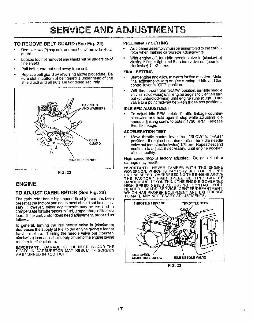
TO REMOVE BELT GUARD (See Fig. 22)• Remove two (2) cap nutsand washers from sideof belt
guard_• Loosen (do not remove) tine shield nut on underside of
tine shield,.
• Pull belt guard out and away from uniL• Replace belt guard by reversing above procedure° Be
sure slot in bottom of belt guard is under head of tineshield bolt and all nuts are tightened securely.
CAP NUTS_IDWASHERS
__-'_ BELT
\\ GUARD
TINE SHIELD NUT
FIG. 22
ENGINE
TO ADJUST CARBURETOR (See Fig. 23)
The carburetor has a high speed fixed jet and has beenpreset at the factory and adjustmentshouId not be neces-saryo However, minor adjustments may be required tocompensate for differences in fuel, temperature, altitude ortoad.. If the carburetor does need adjustment, proceed asfollows.,
In general, turning the idle needle valve in (clockwise)decreases the supply of fuel to the engine giving a leanerfuel!air mixture.. Turning the needle valve out (counter-clockwise) increases the supply of fuel to the engine givinga richer fue!/air mixture°IMPORTANT: DAMAGE TO THE NEEDLES AND THESEATS IN CARBURETOR MAY RESULT IF SCREWSARE TURNED IN TOO TIGHT°
PRELIMINARY SETTING
* Air cleaner assembly must be assembled to the carbu-retor when making carburetor adjustments°
o With engine off, turn idle needle valve in (clockwise)closingit finger tight and then turn valve out (counter-clockwise) I-I/2 turns..
FINAL SETTING
• Start engine and allow to warm for five minutes_ Makefinal adjustmentswith engine running at idle and tinecontroliever in "OFF'' position°
° Withthrottiecontrolin"SLOW"position, turn idleneedlevalve in(clock"wise)untilengine begins to die then turnout (counterclockWise)untilengine runs rough° Turnvalve to a pointmidway between those two positions,.
IDLE RPM ADJUSTMENT
• To adjust idle RPM, rotate throttle linkage counter-clock,vise and hold against stop while adjusting idlespeed adjustingscrew to obtain 1750 RPM. Releasethrottle linkage.,
ACCELERATION TEST
° Move throttle control lever from "SLOW" to "FAST"position° If engine hesitates or dies, turn idle needlevalve out (counterclockwise) 1/8 turn, Repeattest andcontinue to adjust, if necessary, until engine acceter -ates smoothly,,
High speed stop is factory adjusted Do not adjust ordamage may result,
IMPORTANT: NEVER TAMPER WITH THE ENGINEGOVERNOR, WHICH IS FACTORY SET FOR PROPERENGINE SPEED, OVERSPEEDING THE ENGINE ABOVETHE FACTORY HIGH SPEED SETTING CAN BEDANGEROUS,, IFYOU THINKTHE ENGINE-GOVERNEDHIGH SPEED NEEDS ADJUSTING, CONTACT YOURNEAREST SEARS SERVICE CENTER/DEPARTMENT,WHICH HAS PROPER EQUIPMENT AND EXPERIENCETO MAKE ANY NECESSARY ADJUSTMENTS,
THROTTLE LINKAGE THROTTLE STOP
IDLE SPEEDADJUSTING SCREW IDLE NEEDLE VALVE
FIG. 23
17
STORAGE
Immediately prepare your tiiler for storage at the end of theseason or if the unit wilt not be used for 30 days or more.
CAUTION: Never store the tiller withgasoline in the tank inside a buildingwhere fumes may reach an open flameor spark. Allow the engine to cootbefore storing in any enclosure.
i llllll JiJJiJJ i i i
TILLER° Clean entire tiller' (See "CLEANING" in the Customer
Responsibilities section of this manual).
• Inspect and replace belts, if necessary (See belt re-placement instructions in the Service and Adjustmentssection of this manual)_
• Lubricate as shown in the Customer Responsibilitiessection of this manual
° Be sure that all nuts, bolts and screws are securelyfastened_ Inspect moving parts fordamage, breakageand wear_ Replace if necessary_
° Touch up all rusted or chipped paint surfaces; sandlightly before painting,
ENGINE
FUEL SYSTEMIMPORTAN'i": IT IS IMPORTANT TO PREVENT GUMDEPOSITS FROM FORMING IN ESSENTIAL FUELSYSTEM PARTS SUCH AS THE CARBURETOR, FUELFILTER, FUEL HOSE, OR TANK DURING STORAGE°ALSO, EXPERIENCE INDICATES THAT ALCOHOLBLENDED FUELS (CALLED GASOHOL OR USINGETHANOL OR METHANOL) CAN ATTRACT MOISTUREWHICH LEADS TO SEPARATION AND FORMATION OFACIDS DURING STORAGE. ACIDIC GAS CAN DAMAGETHE FUEL SYSTEM OF AN ENGINE WHILE IN STORAGE
• Drain the fuel tank._
• Start the engine and let it run until the fuel lines andcarburetor are empty_
. Never use engine or carburetor cleaner products in thefuel tank or permanent damage may occur'.
° Use fresh fuet next season.
NOTE: Fuel stabilizer is an acceptable alternative inminimizing the formation of fuel gum deposits during stor-age., Add stabilizer to gasoline in fuel tank or storagecontainer° Always follow the mix ratio found on stabilizercontainer. Run engine at least 10 minutes after addingstabilizer to allow the stabilizer to reach the carburetor. Donot drain the gas tank and carburetor if using fuel stabilizer
ENGINE OIL
Drain oil (with engine warm) and replace with clean oil,(See "ENGINE" in the Customer Responsibilities section ofthis manuaI)_
CYLINDERS
• Remove spark plug_
= Pour 1ounce (29 ml) of oil through spark plug hole intocylinder_
° Pull starter handle slowly several times to distribute oil.,
• Replace with new spark plug.,
OTHER
• Do not store gasoline from one season to another_
• Replace your gasoline can if your-can starts to rusLRust and/or dirt in your gasoline will cause problems.
• If possible, store your unit indoors and cover it to giveprotection from dust and dirt°
• Cover your unit with a suitable protective cover thatdoes not retain moisture° Do not use plastic. Plasticcannot breathe which allows condensation to form andwill cause your unit to rusL
IMPORTANT: NEVER COVER TILLER WHILE ENGINEAND EXHAUST AREAS ARE STILL WARM.
18
PROBLEM
Will not start
Hard to start
, ,, ,,,,,, ,,, ,,,,,
Loss of power
i
Engine overheats
Excessive bounce!
difficult handling
Soil bails up or clumps
IU
Engine runs but tillerwon't move
i i i!l
Engine runs but laborswhen tilling
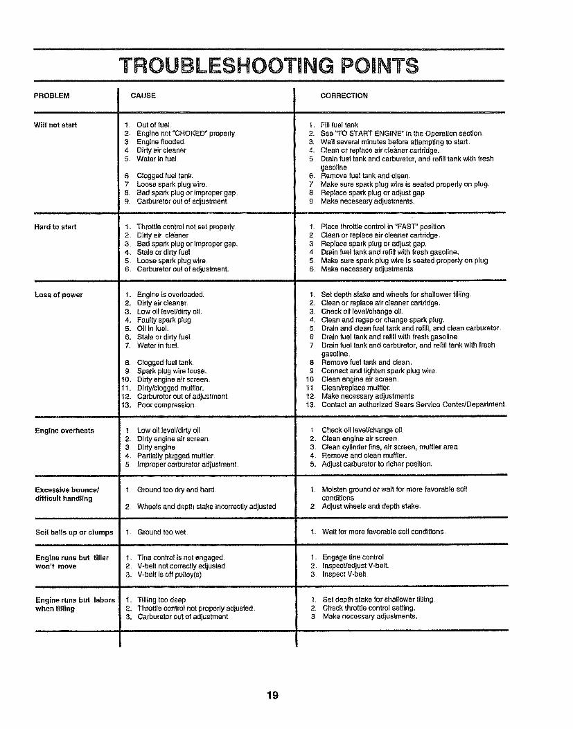
TROUBLESHOOTING POINTS
CAUSE CORRECTION
! Out of fuel2. Engine not"CHOKED" properly,3 Engine flooded4, Dirty air cleaner,5 Water in fuel,
6. Clogged fuel tank..7., Loose spark plug wire.8, Bad spark plug or improper gap9, Carburetor out of adjustment.
1, Throttle control not set properly.2. Dirty air cleaner,3 Bad spark plug or improper gap.,4o Stale or dirty fuel5. Loose spark plug wire.6. Carburetor out of adjustment.,
,,,,,,,,,, Jir, ,.Ir,L,,L,
I, Fi]I fuel tank2., See "TO START ENGINE in the Operation section3. Wait several minutes before attempting to start4,, Clean or replace air clea.ner cartridge.,5 Drain fuel tank and carburetor, and refill tank with fresh
gasoline6. Remove fuel tank and clean.
7. Make sure spark plug wire is seated properly on plug,,8. Replace spark plug or adjust gap,9, Make necessary adjustments,,
t. Place throttle control in "FAST" position2, Clean or replace air cleaner cartridge.3 Replace spark plug or adjust gap,4 Drain fuel tank and refill with fresh gasoline,5
6,Make sure spark ptug wire Is seated properly on plugMake necessary adjustments,
1,, Engine is overloaded.2_ Dkty air cleaner.3. Low oil level/dirty oil.4., Faulty spark plug.5,, Oil In fuel6,, Stale or dirty fuel.7, Water in fuel,.
8. Clogged fuel tank,9 Spark plug wire loose°
t0,, Dirty engine air screen..11,, Dtrty!c_ogged muffler.12o Carburetor out of adjustment.,13, Poor compression,
!, Set depth stake and wheels for shallower tiliingo2, Clean or replace air cleaner cartridge_3, Check ofl leveVchange oil4, Clean and regap or change spark plug,5 Drain and clean fuel tank and refill, and clean carburetor6 Drain fuel tank and refill with fresh gasoline7 Drain fuel tank and carburetor, and refill tank with fresh
gasoline,8, Remove fuel tank and clean,9. Connect and tighten spark plug wire.
10. Clean engine air screen11. Clean/replace muffler,12 Make necessary adjustments13., Contact an authorized Sears Service CentedDepartment,
1. Low otl ]svelldirty oil,2_ Dirty engine air screen,3, Dirty engine4, Partially plugged muffler,5, improper carburetor adjustment,
1, Ground too dry and hard.
2, Wheels and depth stake incorrectlyadjusted
1_ Ground too wet
1.. Tins control is not engaged.2, V-belt not correctly adjusted3,, V-belt is off pulley(s),
t., Tilling too deep,2, Throttle control not properly adiusted.3, Carburetor out of adjustment..
t Check oil leveltchange off2, Clean engine air screen.3. Clean cylinder fins, air screen, muffler area4, Remove and clean muffler.,5., Adjust carburetor to richer position,
!. Moisten ground or walt for more favorable soilconditions
2, Adjust wheels and depth stake,
I.. Walt for more favorable soil conditions
1- Engage line control.2. Inspect/adjust V-beff,3 Inspect V-belt
i i/ /iJ LIIJJILIJJJJIll
1, Set depth stake for shallower tilling2. Check throttle control setting,,3 Make necessary adjustments,
19

REPAIR PARTS
HANDLE ASSEMBLY
TILLER - - MODEL NUMBER 917.295450
2
3
13
4
12
16 525
1718
8
KEY PARTNO. NO.
1 STD533125
2 1369933 110512X4 110632X5 3066J6 2635J7 120000278 232004059 73970500
t0 121t45X11 110514X500t2 98000129
DESCRIPTION
Bolt, Carriage5/16-18 UNC x 2-3/8 Grade 5Panel, ControlAssembly, Handle ColumnGrip, HandleCable, Tine ControlLever, Control, TineRing, ClipScrew, SetLocknut, Flange 5/16-18 UNCClip, CableAssembly, Panel and TubeNut, Flange
20
KEY PARTNO. NO.t3 STD533t0714 136998t5 13990716 106932X17 101248K18 1778Et9 13705620 STD5510372t STD56121022 STD56090723 1909081424 7201052025 137640
DESCRIPTION
Bolt, Carriage 5116-18 x 3/4Bracket, Reverse RodGrommetKnob, Control, ReverseReverse Rod, UpperPin, RetainingReverse Rod, LowerWasher 13/32 x 13/16 x t 6 GaugePin, Cotter 1/8 x 3/4Pin, Cotter 3132 x 1/2Washer 9/32 x 1/2 x 14 GaugeBolt 5/16-18 x 2-1/2Bushing, Reverse Rod Bracket
NOTE: All component dimensions given in U,.S. inches.1 inch = 25,.4mm
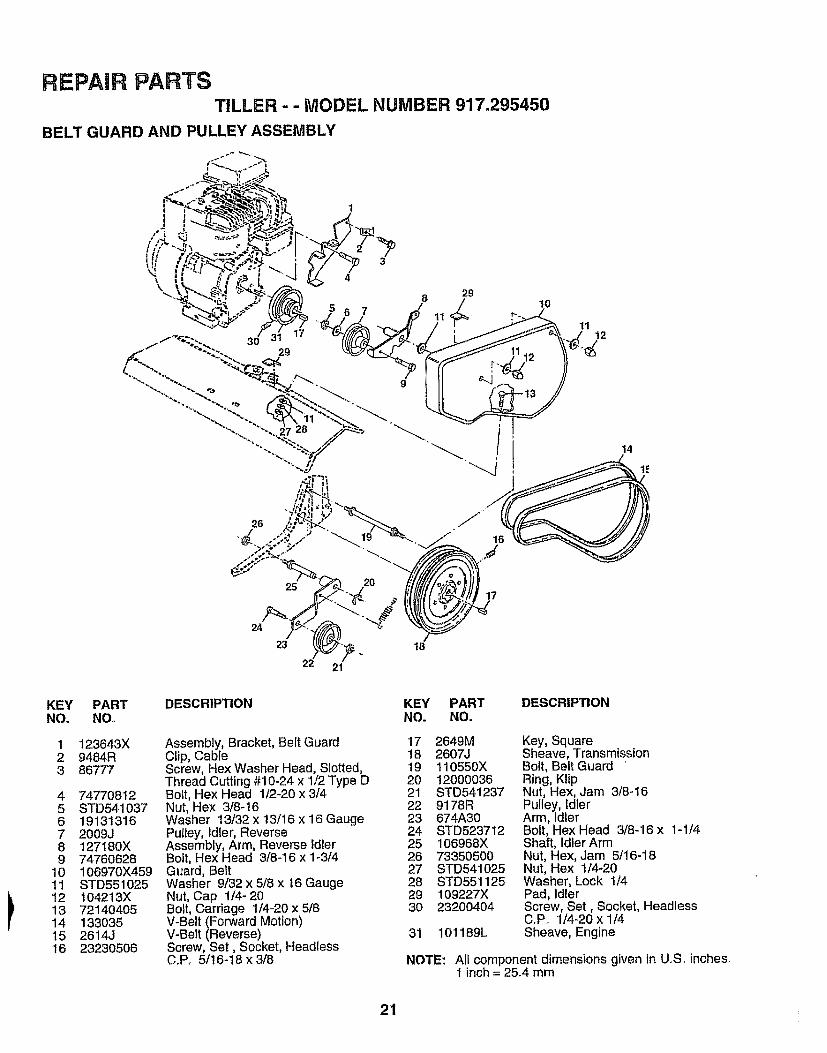
REPAmRPARTSTILLER -- MODEL NUMBER 917.295450
BELT GUARD AND PULLEY ASSEMBLY
\\
4
7
29
_/;:_ 1011
12
9
26
25
24
23
21
20
18
17
KEY PARTNO, NO,
1 !23643X2 9484R3 86777
4 747708125 STD5410376 191313167 2009J8 t27180X9 74760628
10 106970X45911 STD55102512 t04213X13 721404O514 13303515 2614J16 23230506
DESCRIPTION
Assembly, Bracket, Belt GuardClip, CableScrew, Hex Washer Head, Slotted,Thread Cutting #10-24 x 1/2 Type DBolt, Hex Head 1/2-20 x 3/4Nut, Hex 3/8-16Washer 13/32 x 13/16 x 16 GaugePulley, Idler, ReverseAssembly, Arm, Reverse IdlerBolt, Hex Head 3/8-16 x 1-3/4Guard, BeltWasher 9/32 x 5/8 x t6 GaugeNut, Cap 1/4- 20Bolt, Carriage 1/4-20 x 5/8V-Belt (Forward Motion)V-Belt (Reverse)Screw, Set, Socket, HeadlessC.P, 5/16-18 x 3/8
KEY PART DESCRIPTIONNO. NO.
17 2649M Key, Square18 2607J Sheave, Transmission19 110550X Bolt, Belt Guard20 12000036 Ring, Klip21 STD541237 Nut, Hex, Jam 3/8-1622 9178R Pulley, Id[er23 674A30 Arm, IdEer24 STD523712 Bolt, Hex Head 3/8-16x 1-1/425 106968X Shaft, IdlerArm26 73350500 Nut, Hex, Jam 5/16-1827 STD541025 Nut, Hex 1/4-2028 STD551125 Washer, Lock 1/429 109227X Pad, Idler30 23200404 Screw, Set, Socket, Headless
C..Po 1/4-20 x 1/431 101189L Sheave, Engine
NOTE: Al! component dimensions given in U.S.. inches.1 inch = 25.4 mm
21
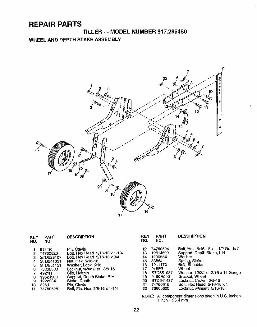
REPAIR PARTSTILLER-- MODEL NUMBER 917.295450
WHEEL AND DEPTH STAKE ASSEMBLY
17 <,
19 20
7
22.d
/
20 19 _"18
1617
KEYNO,
123456789
1011
PARTNO.
9194R74760520STD5231078TD541031STD551131738006004921H1952J5O0122233X326J74780628
DESCRIPTION
Pin, ClevisBolt, Hex Head 5!16-18 x 1-1/4Bolt, Hex Head 5/16-18 x 314Nut, Hex 5/16-18Washer, Lock 5/16Locknut, v#washer 3/8-16Clip, HairpinSupport, Depth Stake, R,H.Stake, DepthPin, ClevisBolt, Fin, Hex 3/8-16 x 1-3/4
KEY PART DESCRIPTIONNO. NO.
12 74760524 Boit, Hex 5116-18 x 1-1t2 Grade 213 1951J500 Support, Depth Stake, L.H..14 120958X Washer15 5388J Spring, Stake16 121117X Bolt, Shoulder7 9188R Wheel
18 STD551037 Washer 13/32 x 13/16 x 1I Gauge19 9190R500 Bracket, Wheel20 STD541437 Locknut, Crown 3/8-1621 74760516 Bolt, Hex Head 5/16-18 x t22 73800500 Locknut, w/insert 5/16-18
NOTE: All component dimensions given in U.S inches°1 inch = 25.4 mm
22
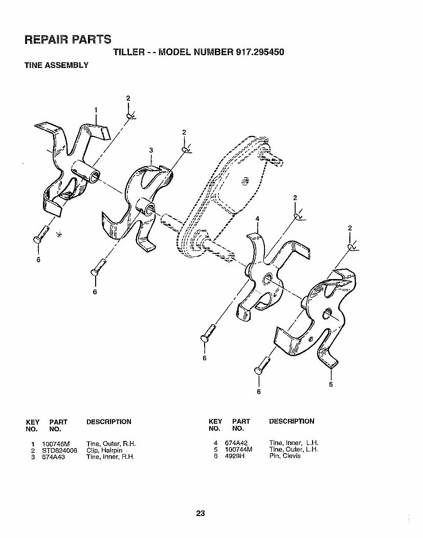
REPAIR PARTSTILLER -- MODEL NUMBER 917.295450
TINE ASSEMBLY
6
2
6
i6
KEYNO,
123
PARTNO.
100746MSTD624008674A43
DESCRIPTION KEY PART DESCRIPTIONNO. NO.
Tine, Outer, R.H. 4 674A42 Tine, Inner, L.H.Clip, Hairpin 5 100744M Tine, Outer, L.H.Tine, Inner, R.H. 6 4929H Pin, Clevis
23
REPAIR PARTS
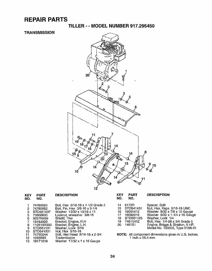
TRANSMISSION
TILLER - - MODEL NUMBER 917.295450
2O
3
3
7
14
14
KEY PAR'('NO. NO.
1 747605242 747806523 STD5510375 738006006 9057R4597 1949J5008 110519X5009 STD551131
10 STD54103111 7476054412 126669X13 19171616
1415
DESCRIPTION
12
Bolt, Hex 5/16-18 x 1-1/2 Grade 2Bolt, Fin, Hex 3/8-16 x 3-1/4Washer 13/32 x 13/16 x 11Locknut, w/washer 3/8-16Shield, TineBracket, Engine, R_H.Bracket, Engine, L.H.Washer, Lock 5/16Nut, Hex 5/16-18Bolt, Hex Head 5/16-18 x 2-3/4Transm{ssionWasher 17/32 x 1 x 16 Gauge
10
11
KEY PARTNO. NO.
DESCRIPTION
14 9173R15 STD54143116 1909141217 1909201618 STD551 I2519 7461041220 146151
Spacer, SplitNut, Hex, Keps 5/16-18 UNCWasher 9/32 x 7/8 x 12 GaugeWasher 9/32 x 1-1/4 x 16 GaugeWasher', Lock 1/4Bolt, Hex 1/4-28 x 3/4 Grade 5Engine, Briggs & Stratton, 5 HP,Model No=133202, Type 0156-01
NOTE: All component dimensions given in U_S, inche&1 inch = 25.4 mm
24
REPAIR PARTS
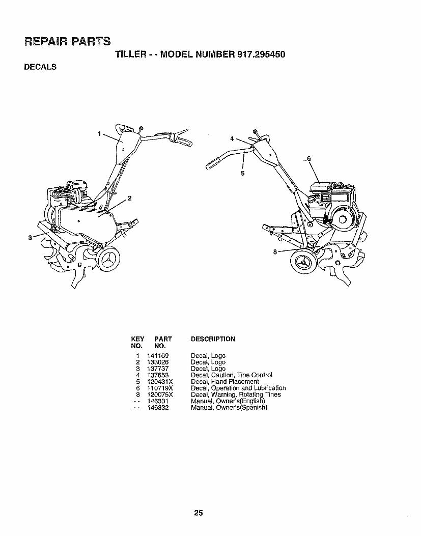
DECALS
TILLER - - MODEL NUMBER 917.295450
2
5
KEY PARTNO. NO.
1 1411692 1330263 1377374 1376535 I20431X6 110719X8 120075X
- - 146331- - 146332
DESCRIPTION
Decal, LogoDecal, LogoDecal, LogoDecal, Caution, Tine ControlDecal, Hand PlacementDecal, Operation and LubricationDecal, Warning, Rotating TinesManual, Owner's(English)Manual, Owner's(Spanish)
25
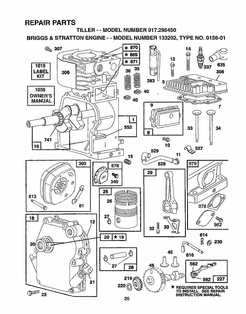
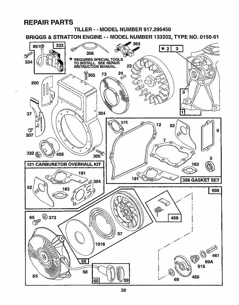
REPAIR PARTSTILLER - - MODEL NUMBER 917.295450
BRIGGS & STRATTON ENGINE -- MODEL NUMBER 133202, TYPE NO. 0156-01
1019
LABEL 306KIT
1058OWNER'S
741 t l
36 35
_ 4o
552
613
81
22
llll ill W
15
26
i
978
INSTRUCTION MANUAL,26
RE!PARRPARTSTILLER -- MODEL NUMBER 917.295450
BRIGGS & STRATTON ENGINE - - MODEL NUMBER 133202, TYPE NO. 0156-01
97634 _ _202
127
203
205
153 __
995 414153
542 202A__ .....................
190A o__19o_ °_" 191
209916
526
181
621
224
2O4
223
967
27
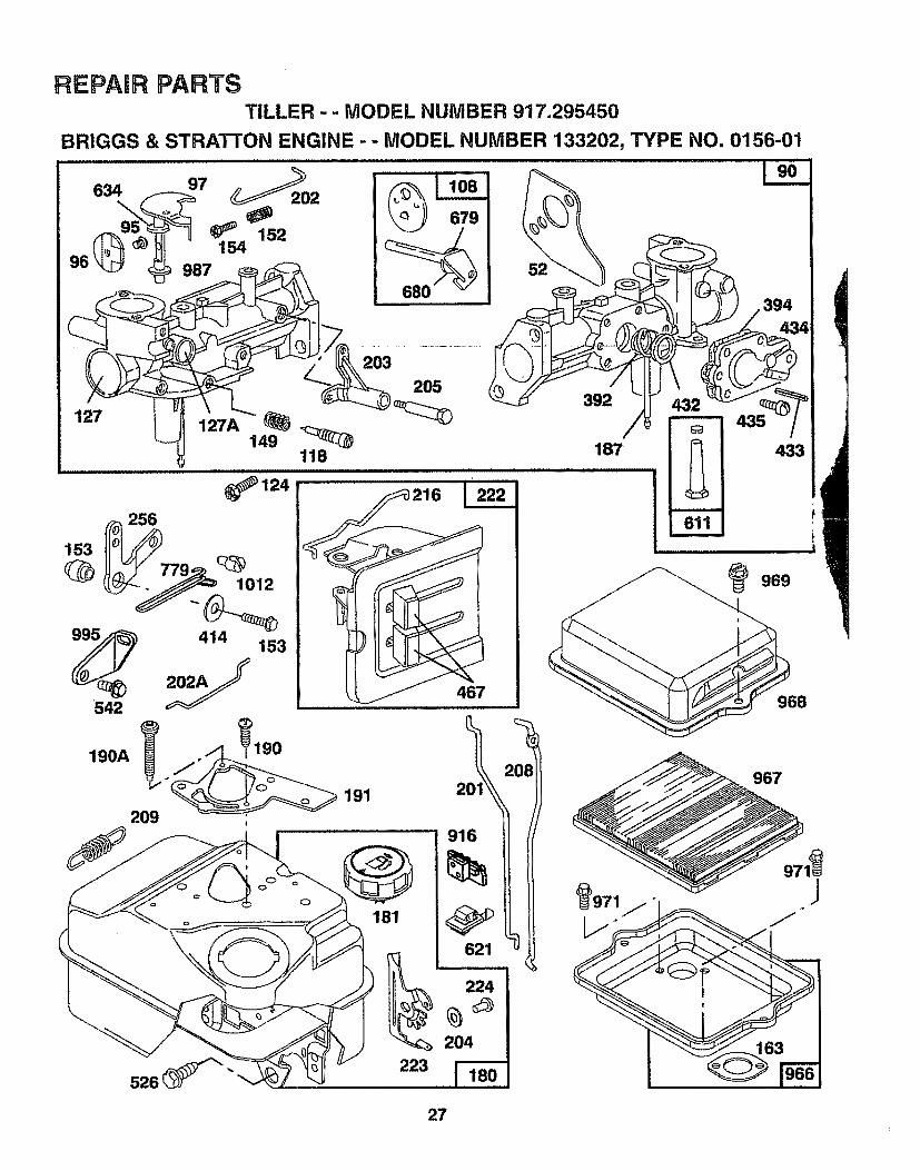
REPAIR PARTSTILLER - - MODEL NUMBER 917.295450
BRIGGS & STRATTON ENGINE - - MODEL NUMBER 133202, TYPE NO. 0156-01
334
200
3O7
332 455
121 CARBURETOR OVERHAUL KIT
3°°_r REQUIRES SPECIAL TOOLS
TO INSTALL SEE REPAIRINSTRUCTION MANUAL, 23'
191
73 24O
7
529
3
163 (_
J3S8Q_SKETSE'T163
1016
58
69
461
69A515
456
28
REPAIR PARTSTILLER -- MODEL NUMBER 917.295450
BRIGGS & STRATTON ENGINE - - MODEL NUMBER '133202, TYPE NO. 0156-01
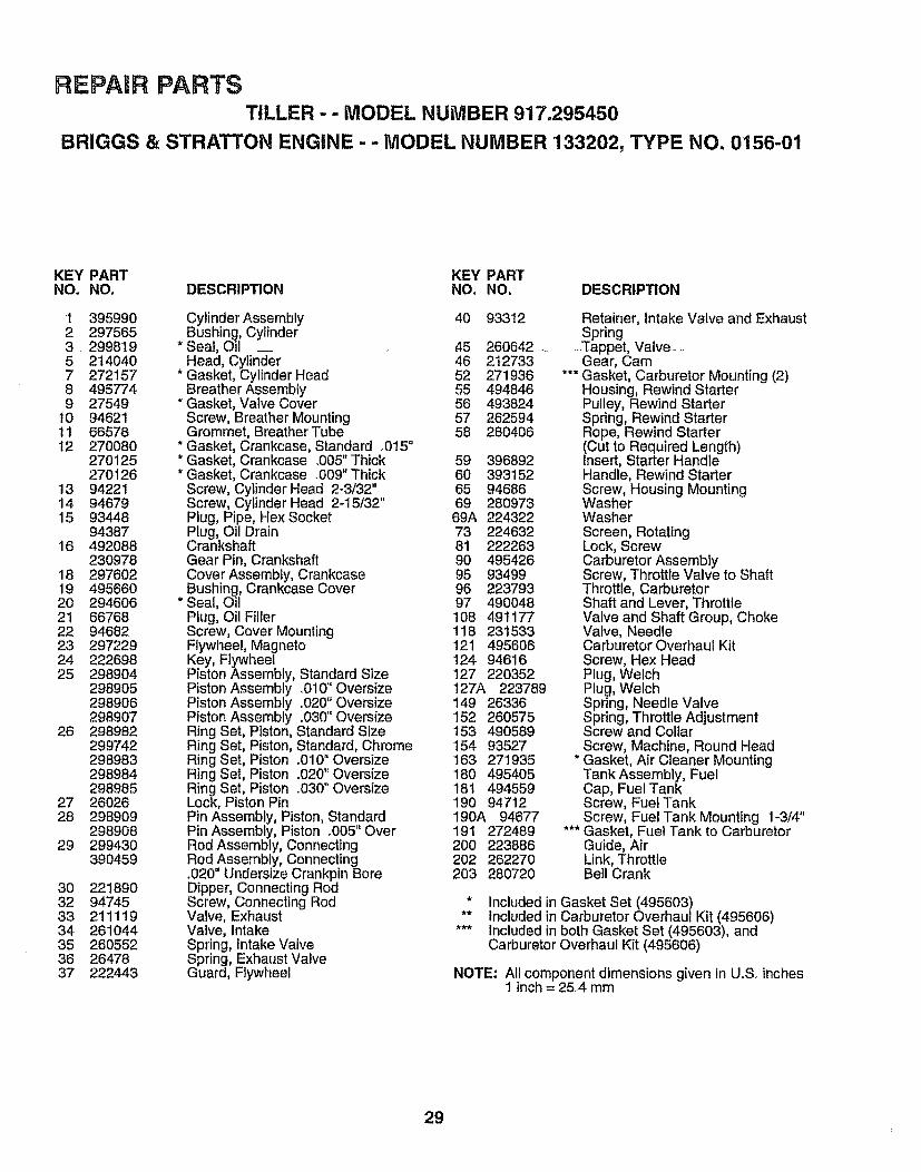
KEY PART KEY PARTNO. NO, DESCRIPTION NO. NO. DESCRIPTION
t 3959902 2975653 2998't95 2140407 2721578 4957749 27549
10 9462111 66578t2 270080
270125270126
13 9422114 9467915 93448
9438716 492088
23097818 2976O219 49566020 2946062t 6676822 9468223 29722924 22269825 298904
298905298906298907
26 298982299742298983298984298985
27 2602628 298909
29890829 299430
390459
30323334353637
2218909474521111926104426055226478222443
Cylinder Assembly 40 93312Bushing, Cylinder
*Seal, Oil _ 45 260642 _Head, Cylinder 46 212733
* Gasket, Cylinder Head 52 271936Breather Assembly 55 494846
* Gasket, Valve Cover 56 493824Screw, Breather Mounting 57 262594Grommet, Breather Tube 58 280406
* Gasket, Crankcase, Standard o0t5"* Gasket, Crankcase °005" Thick 59 396892* Gasket, Crankcase .009" Thick 60 393152
Screw, Cylinder Head 2-3/32" 65 94686Screw, Cylinder Head 2-15132" 69 280973Plug, Pipe, Hex Socket 69A 224322Plug, Oil Drain 73 224632Crankshaft 81 222263Gear Pin, Crankshaft 90 495426Cover Assembly, Crankcase 95 93499Bushing, Crankcase Cover 96 223793
* Seat, Oil 97 490048Plug, Oil Filler 108 491177Screw, Cover Mounting 118 231533Flywheel, Magneto 121 495606Key, Flywheel 124 94616Piston Assembly, Standard Size 127 220352Piston Assembly .010" Oversize 127A 223789Piston Assembly .020" Oversize 149 26336Piston Assembly .030" Oversize 152 260575Ring Set, Piston, Standard Size t53 490589Ring Set, Piston, Standard, Chrome 154 93527Ring Set, Piston .010" Oversize 163 271935Ring Set, Piston .020" Oversize 180 495405Ring Set, Piston .O30" Oversize 181 494559Lock, Piston Pin 190 94712Pin Assembly, Piston, Standard 190A 94677Pin Assembly, Piston .005" Over 191 272489Rod Assembly, Connecting 200 223886Rod Assembly, Connecting 202 262270.020" Undersize Crankpin Bore 203 280720Dipper, Connecting RodScrew, Connecting RodValve, ExhaustValve, intakeSpring, intake ValveSpring, Exhaust ValveGuard, Flywheel
Retainer, intake Valve and ExhaustSpring
-Tappet, Valve--.Gear, Cam
*** Gasket, Carburetor Mounting (2)Housing, Rewind StarterPulley, Rewind StarterSpring, Rewind StarterRope, Rewind Starter(Cut to Required Length)Insert, Starter HandleHandle, Rewind StarterScrew, Housing MountingWasherWasherScreen, RotatingLock, ScrewCarburetor AssemblyScrew, Throttle Valve to ShaftThrottle, CarburetorShaft and Lever, ThrottleValve and Shaft Group, ChokeValve, NeedleCarburetor Overhaul KitScrew, Hex HeadPlug, WelchPlug, WelchSpring, Needle ValveSpring, Throttle AdjustmentScrew and CollarScrew, Machine, Round Head
* Gasket, Air Cleaner MountingTank Assembly, FuelCap, Fuel TankScrew, Fuel TankScrew, Fuel Tank Mounting 1_3/4"
*** Gasket, Fuel Tank to CarburetorGuide, AirLink, ThrottleBell Crank
* Included in Gasket Set (495603)** included in Carburetor Overhaul Kit (495606)
*** Included in both Gasket Set (495603), andCarburetor Overhaul Kit (495606)
NOTE: All component dimensions given in UoS°inches1 inch = 25°4 mm
29

REPAIR PARTSTILLER - - MODEL NUMBER 917.295450
BRIGGS & STRATTON ENGINE - - MODEL NUMBER 133202, TYPE NO. 0156-01
KEY PART KEY PARTNO. NO. DESCRIPTION NO. NO. DESCRIPTION
204 222962 Bushing, Governor Lever, Flat 528 231550 Tube, Breather205 231520 Screw, Shoulder 529 67838 Grommet, Breather Tube208 262279 Rod, Speed Control 542 93572 Screw209 262283 Spring, Governor 552 231079 Bushing, Governer Crank216 262359 Link, Choke 562 92613 Bolt, Governor Lever219 494845 Gear, Governor 592 231082 Nut, Hex220 221551 Washer, Thrust 608 495766 Starter Assembly, Rewind222 490649 Panel, Control 611 391813 Fuel Pipe and Clip Assembly223 223455 Lever, Governor Control 613 93935 Screw, Hex Head, Shoulder224 93491 Rivet, Governor Control Lever 614 93306 Pin, Cotter'
Mounting 615 93307 Retainer, E-Ring227 490374 Lever Assembly, Governor 6t6 231077 Crank, Governor230 222450 Washer, Governor Lever 621 396847 Switch, Stop256 223813 Crank, Bell 634 271853 Washer', Throttle Shaft, Foam257 93543 Screw, Sems, Hex Head 635 66538 Elbow, Spark Plug300 393615 Muffler, Exhaust 676 393757 Deflector, Exhaust, Side Outlet304 495759 Housing, Blower 679 270382 Washer, Foam305 94619 Screw, Blower Housing Mounting 680 221839 Washer, Brass306 221511 Shield, Cylinder 741 261696 Gear, Timing307 94680 Screw, Cylinder Shield 779 262570 Link, Speed Control308 224738 Cover, Cylinder Head 851 221798 Cable Terminal, ignition332 92284 Nut, Flywheet 869 211787 Seat, Intake Valve, Standard333 397358 Armature Group 870 21!172 Seat, Exhaust Valve, Standard334 93414 Screw, Armature Mounting 871 262001 Guide, Exhaust Valve337 802592 Plug, Spark 63709 Guide, Intake Valve346 93705 Screw, Seres 916 280321 Rack, Gear Control356 398808 Wire, Ground 966 492797 Base, Air Cleaner358 495603 Gasket Set 967 491588 Filter, Air Cleaner363 19069 Flywheel Puller 968 495357 Cover, Air Cleaner373 92987 Nut, Hex 969 490073 Screw, Air Cleaner383 89838 Wrench, Spark Plug 971 94018 Screw, Hex Head392 262328 Spring, Fuel Pump Diaphragm 987 398970 Seal, Throttle Shaft394 272538 ** Diaphragm 995 223887 Lever, Bracket Assembly414 220982 Washer 1012 490507 Retainer, Link432 221377 Cap, Spring 1016 224278 Spacer433 93265 Pin, Diaphragm Cover434 214021 Cover, Diaphragm RPM Settings: Low Speed: 1750-1950435 93141 Screw, Diaphragm Cover High Speed: 3400-3600455 224250 Cup, Starter456 224321 Retainer * Included in Gasket Set (495603)459 492833 Pawl, Starter ** Included in Carburetor Overhaul Kit (495606)461 262626 Pin, Spring *** Included in both Gasket Set (495603), and467 280715 Knob, Control Carburetor Overhaul Kit (495606)515 262625 Spring526 94659 Screw, Sems, Tank Bracket Mount. NOTE: All component dimensions given in U.So inches527 223786 Clamp, Breather-Tube 1 inch = 25_4 mm
3O

SERV NOTES
31
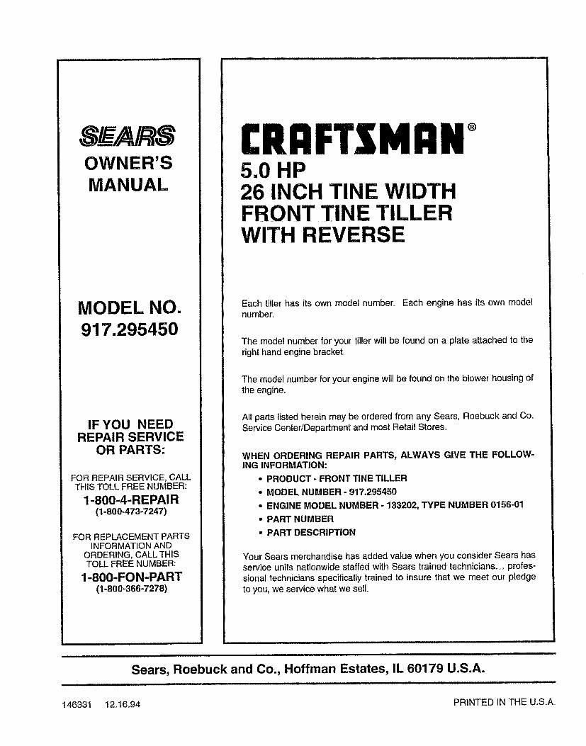
OWNER'SMANUAL
MODEL NO.917.295450
IF YOU NEEDREPAIR SERVICE
OR PARTS:
FOR REPAIR SERVICE, CALLTHIS TOLL FREE NUMBER:
1-800-4-REPAIR(1-800-473-7247)
FOR REPLACEMENT PARTSINFORMATION AND
ORDERING, CALL THISTOLL FREE NUMBER:
1-800-FON-PART(1+800+366-7278)
1:1111 MAIl +5.0 HP26 INCH TINE WIDTHFRONT TINE TILLERWITH REVERSE
Each tiller has its own model number'+ Each engine has its own modelnumber.
The model number for' your tillerwill be found on a plate attached to theright hand engine bracket,.
The model number for your engine will be found on the blower housingofthe engine,,
All parts listed herein may be ordered from any Sears, Roebuck and Co+Service Center/Department and most Retail Stores,,
WHEN ORDERING REPAIR PARTS, ALWAYS GIVE THE FOLLOW-ING INFORMATION:
• PRODUCT - FRONT TINE TILLER
• MODEL NUMBER - 917.295450
- ENGINE MODEL NUMBER - 133202, TYPE NUMBER 0156-01
• PART NUMBER
,, PART DESCRIPTION
Your Sears merchandise has added value when you consider Sears hasservice units nationwide staffed with Sears trained technicians+++profes-sional technicians specifically trained to insure that we meet our pledgeto you, we service what we sell,,
Sears, Roebuck and Co., Hoffman Estates, IL 60179 U.S.A.
146331 t2+16+94 PRINTED IN THE U.S+A+