tillermaxx tillers - haytools manual.pdf · tillermaxx tillers ' tillermaxx 2 caution ... it...
TRANSCRIPT

TILLERMAXX
Tillers

© TILLERMAXX 2
CAUTION THE FOLLOWING SAFETY PRECAUTIONS SHOULD BE THOROUGHLY UNDERSTOOD BEFORE ATTEMPTING TO BEGIN ASSEMBLING THIS MACHINE.
1. Select an area for assembly that is clean and free of any debris, which might cause persons working on the assembly to trip.
2. Do not lift heavy parts or assemblies. Use crane, jack, tackle, fork trucks or other mechanical devices.
3. Preview the assembly instructions in your operator�s manual before proceeding further. 4. If the assembly instructions call for parts or assemblies to be blocked up, use only
blocking material that is in good condition and is capable of handling the weight of the assembly to be blocked. Also insure that the blocking material is on a clean, dry surface.
5. Never put hands, or any part of your body, under blocked up assemblies if at all possible. 6. After completing assembly, thoroughly inspect the machine to be sure that all nuts, bolts,
hydraulic fittings or any other fastened assemblies have been tightened. 7. Before operating the machine, thoroughly read the operation section of your operator�s
manual. 8. Before operating, read the maintenance section of your operator�s manual to be sure that
any parts requiring lubrication, such as gearboxes, are full, to avoid any possible damage.
9. Before operating equipment � if you have any questions regarding the proper assembly or operation, contact your dealer or representative.
STATEMENT OF POLICY It is the policy of TILLERMAXX/MINOS to improve its products where it is possible and practical to do so. TILLERMAXX/MINOS reserves the right to make changes or improvements in design and construction at any time, without incurring the obligation to make these changes on previously manufactured units.
TO THE OWNER: Read this manual before using your rotary tiller. This manual is provided to give you the necessary operating and maintenance instructions for keeping your rotary tiller in top operating condition. Please read this manual thoroughly. Understand what each control is for and how to use it. Observe all safety signs on the machine and noted throughout the manual for safe operation of the implement. Keep this manual handy for ready reference. Like all mechanical products, it will require cleaning and upkeep. Lubricate the tiller as specified. Use only genuine TILLERMAXX/MINOS Equipment service parts. Substitute parts will void warranty and may not meet standards required for safe and satisfactory operation.

© TILLERMAXX 3
RETAIL CUSTOMER�S RESPONSIBILITY It is the retail customer and/or Operator�s responsibility to read the Operator�s Manual, to operate, lubricate, maintain, and store the product in accordance with all instructions and safety procedures. Failure of the operator to read the Operator�s Manual is a misuse of this equipment. It is the retail customer and/or Operator�s responsibility to inspect the product and to have any part(s) repaired or replaced when continued operation would cause damage or excessive wear to other parts or cause safety hazard. It is the retail customer and/or Operator�s responsibility to deliver the product to the authorized TILLERMAXX/MINOS Dealer, from whom it was purchased, for service or replacement of defective parts that are covered by warranty. Repairs to be submitted for warranty consideration must be made within thirty (30) days of failure. It is the retail customer and/or Operator�s responsibility for any cost incurred by the Dealer for traveling to or hauling of the product for the purpose of performing a warranty obligation or inspection.
CHECKLISTS DELIVERY CHECKLIST Inspect the tiller thoroughly after assembly to be certain it is set up set up properly. The following checklist is a reminder of points to inspect. Check off each as it is found satisfactory or after proper adjustment is made.
Check operator�s manual and familiarize the operator with all sections of it. Check that all safety shielding is in place. Check all bolts to be sure they are tight or adjusted properly at hinged locations. Check that all cotter pins are properly installed. Check PTO driveline. Make sure it is the correct length to operate tiller with intended
tractor. Check all lubrication points with grease fittings have been lubricated. Check that blades have been properly installed. Check all blade beam bolts. Check tiller attitude, after mounting on tractor. Check that gearbox is properly serviced and seals are not leaking. Check shear bolt for proper grade and installation. Check front of input gearbox shaft and make sure that snap ring is properly installed. Check that all safety signs (decals) are in place and readable.

© TILLERMAXX 4
DAILY CHECKLIST
Check that tiller is properly and securely attached to tractor. Check that all nuts and bolts are secure and that all safety shields are in place. Check condition of blades and security of attachment. Check that PTO driveline shields are securely locked and clear the front all parts of the
frame. Adjust the tractor top link so the front of the tiller is level with the rear. Then raise the
tractor lift very slowly; making sure that the front driveshaft shield does not hit the draw bar. If it does, damage will be done to the driveshaft shield and, if it hits hard enough, it will also damage the driveshaft itself.
NOTE: This type of damage is not covered under warranty, as it is totally under the control and the responsibility of the operator. IMPORTANT! GEARBOXS WERE NOT FILLED AT FACTORY. IT MUST BE SERVICED PRIOR TO OPERATING THE TILLER. FILL TO PROPER WITH LEVEL WITH 80/90 GEAR OIL. FAILURE TO SERVICE WILL RESULT IN DAMAGE TO GEARBOX(S).
TO THE OWNER / OPERATOR / DEALER All implements with moving parts are potentially hazardous. There is no substitute for a cautious, safe minded operator who recognizes the potential hazards and follows reasonable safety practices. The manufacturer has designed this implement to be used with all its safety equipment properly attached to minimize the chance of accidents. BEFORE YOU START!! Read the safety messages on the implement and shown in your manual. Observe the rules of safety and common sense! THE SAFETY ALERT SYMBOL IDENTIFIES IMPORTANT SAFETY WARNING MESSAGES. CAREFULLY READ EACH WARNING MESSAGE THAT FOLLOWS. FAILURE TO UNDERSTAND AND OBEY A SAFETY WARNING, OR RECOGNIZE A SAFETY HAZARD, COULD RESULT IN AN INJURY OR DEATH TO YOU OR OTHERS AROUND YOU. THE OPERATOR IS ULTIMATELY RESPONSIBLE FOR THE SAFETY OF HIM/HERSELF, AS WELL AS OTHERS, IN THE OPERATING AREA OF THE EQUIPMENT. UNDERSTAND SIGNAL WORDS A signal word � DANGER, WARNING OR CAUTION- is used with the safety-alert symbol. DANGER identifies the most serious hazards. DANGER and WARNING safety signs are located near the specific hazard. CAUTION safety signs list general precautions. The safety-alert symbol is also used in this manual to call attention to safety messages.
© TILLERMAXX 5
IMPORTANT SAFETY INFORMATION! Working with unfamiliar equipment can lead to careless injuries. Read this manual, and the manual for your tractor, before assembly or operating, to acquaint yourself with the machines. It is the implement owner�s responsibility, if this machine is used by any person other than you, is loaned or rented, to make certain that the operator, prior to operating:
1. Reads and understands the operator�s manuals. 2. Is instructed in safe and proper use.
The use of this equipment is subject to certain hazards, which cannot be protected against by mechanical means or product design. All operators of this equipment must read and understand this entire manual, paying particular attention to safety and operating instructions, prior to using. If there is something in this manual you do not understand, ask your supervisor, or dealer, to explain it to you. Most accidents occur because of neglect or carelessness. Keep all helpers and bystanders� twenty-five feet (25�) from an operating rear blade. Only properly trained people should operate this machine. It is recommended the tractor be equipped with Rollover Protection System (ROPS) and a seat belt that is used. Always stop the tractor, set brake, shut off the tractor engine, remove the tractor key, and lower the implement to the ground before dismounting tractor. Never leave tractor or equipment running while unattended. Please remember it is important that you read and heed the safety signs on the rear blade, and the safety rules set forth. Clean or replace all safety signs if they cannot be read clearly or understood. They are there for your safety as well as the safety of others. The safe use of this machine is strictly up to you, the operator. EQUIPMENT SAFETY GUIDELINES Safety of the operator is one of the main concerns in designing and developing a new piece of equipment. Designers and manufacturers build in as many safety features as possible. However, every year many accidents occur which could have been avoided by a few seconds of thought and more careful approach to handling equipment. You, the operator, can avoid many accidents by observing the following precautions in this section. To avoid personal injury, study the following precautions and insist those working with you, or for you, follow them. In order to provide a better view, certain photographs or illustrations in this manual may show an assembly With a safety shield removed. However equipment should never be operated in this condition. Keep all shields in place. If shield removal becomes necessary for repairs, replace the shield prior to use. Replace any CAUTION, WARNING, DANGER or instruction safety sign that is not readable or is missing. Location of such safety signs is indicated in this booklet. Never use alcoholic beverages or drugs, which can hinder alertness or coordination while operating this equipment. Consult your doctor about operating this machine while taking prescription medications. Review the safety instructions with all users annually. This equipment is dangerous to children and persons unfamiliar with its operation. The operator should be a responsible adult familiar with farm machinery and trained in this equipment�s operations. Do not allow persons to operate or assemble this unit until they have read this manual and have developed a thorough understanding of the safety precautions and how it works. To prevent injury or death, use a tractor equipped with a Roll-Over Protective System (ROPS). Do not paint over, remove or deface any safety signs or warning signs on your equipment. Observe all safety signs and practice the instruction on them. Never exceed the limits of a piece of machinery. If its ability to do a job, or to do so safely, is in question � Don�t try it. Do not
© TILLERMAXX 6
modify the equipment in any way. Unauthorized modification may impair the function and/or safety and could affect the life of the equipment. In addition to the design and configuration of this implement, including Safety Signs and Safety Equipment, hazard control and accident prevention are dependant upon the awareness, concern, prudence, and proper training of personnel involved in the operation, transport, maintenance, and storage of the machine. Refer also to safety messages and operation instruction in each of the appropriate sections of the tractor and tiller manuals. Pay close attention to the safety signs attached to the tractor and tiller. Keep safety signs clean and legible at all times. Replace safety signs that are missing or become illegible. Replaced parts that displayed a safety sign should also display the current sign. Safety signs are available from your Distributor or Dealer Parts Department or the Factory. Safety is a primary concern in the design and manufacture of our products. Unfortunately, our efforts to provide safe equipment can be wiped out by a single careless act of an operator. In addition to the design and configuration of equipment, hazard control and accident prevention are dependent upon the awareness, concern, prudence and proper training of personnel involved in the operation, transport, maintenance and storage of equipment. It has been said, �the best safety device is an informed, careful operator.� We ask you to be that kind of an operator. It is the operator�s responsibility to read and understand ALL Safety and Operating instructions in the manual and to follow them. Accidents can be avoided. Working with unfamiliar equipment can lead to careless injuries. Read this manual, and the manual for your tractor, before assembly or operating, to acquaint yourself with the machines. It is the implement owner�s responsibility, if this machine is used by any person other than you, is loaned or rented, to make certain that the operator, prior to operating:
3. Reads and understands the operator�s manuals. 4. Is instructed in safe and proper use.
Know your controls and how to stop the tractor, engine, and tiller quickly in an emergency. Read this manual and the one provided with your tractor. Train all new personnel and review instructions frequently with existing workers. A person who has not read and understood all operating and safety instructions is not qualified to operate the machine. An untrained operator exposes himself and bystanders to possible serious injury or death. Do not allow children to operate this machine. PREPARATION Never operate the tractor or tiller until you have read and completely understand this manual, the Tractor Operator�s Manual, and each of the Safety Messages found on the safety signs on the tractor and tiller. Personal protection equipment including hardhat, safety glasses, safety shoes, and gloves are recommended during assembly, installation, operation, adjustment, maintaining, repairing, removal, or moving the implement. Do not allow long hair, loose clothes or jewelry to be around moving parts. PROLONGED EXPOSURE TO LOUD NOISE MAY CAUSE PERMANENT HEARING LOSS! Tractors with or without Tillers attached can often be noisy enough to cause permanent, partial hearing loss. We recommend that you wear hearing protection on a full-time basis if the noise in the Operator�s position exceeds 80db. Noise over 85db on a long-term basis can cause severe hearing loss. Noise over 90db adjacent to the operator over a long-term basis may cause permanent, total hearing loss. NOTE: hearing loss from loud noise (from tractors, chain saws,

© TILLERMAXX 7
radios, and other such sources close to the ear) is cumulative over a lifetime without hope of natural recovery. Operate the tiller only with a tractor equipped with an approved Roll-Over Protection System (ROPS). Always wear your seatbelt on tractors equipped with ROPS. Serious injury or even death could result from falling off the tractor, particularly during a turn over when the operator could be pinned under the ROPS or the tractor. Clear the area to be cut of stones, branches or other debris that might be thrown, causing injury or damage. Operate only in daylight or good artificial light. Ensure tiller is properly mounted, adjusted and in good operating condition. Make sure driveline spring-activated locking pin or balls operate freely and are seated firmly in tractor PTO stub shaft groove. Ensure that all safety shielding and safety signs are properly installed and in good condition.

© TILLERMAXX 8
USE ONLY 540 RPM PTO SPEED with TILLERMAXX/MINOS tillers.
Attach tiller to tractor 3-point hitch per tractor operator�s manual. Do not attach driveline at this time. NOTE Due to the many variations in tractor/implement hitch points and corresponding differences in distances between tractor PTO shafts and implement input shafts, drivelines may need to be shortened as described in the following steps:
1. Raise and lower tiller to determine position with shortest distance between the tractor PTO shaft and gearbox input shaft. Shut down tractor, leaving tiller in position of shortest distance. Securely block
tiller in position. 2. Pull driveline apart. Attach outer (female) section to tractor PTO shaft. Pull on driveline section to be sure
that yoke locks into place. 3. Hold driveline sections parallel to each other to determine if it is too long. Each section should end 4. Raise and lower tiller to determine position with greatest distance between PTO shaft and gearbox
input shaft. Shut down tractor leaving tiller in position of greatest distance. Securely block tiller in position.
5. Hold driveline sections parallel to each other and check for minimum 6 inches overlap. If driveline has been marked for cutting, overlap will be the distance between two marks. If driveline has less than minimum overlap, do not use.
Pre-Operation Check List
Check blades and rotor to be sure that no foreign objects such as wire or steel strapping bands are wrapped around them.
Check blade bolts for tightness. Tighten to 118 ft./lbs. Inspect blades for wear. Replace if necessary. Make certain driveline shields are in place and in good repair. During operation, listen for abnormal sounds Driveline Universal Joints - Apply multi-purpose grease with grease gun before use. Driveline Guard - Apply 2-3 shots of multipurpose grease with grease gun to plastic fitting. Driveline - Disconnect PTO driveline, pull the two sections apart, apply thin coat of multi-purpose grease to
inside of outer (female) section. Reassemble sections and install. Pull each section to be sure driveline and shields are securely connected. Make certain PTO shielding is in good condition.
Rotor Shaft Bearing - Apply 2-3 shots of multipurpose grease with hand pump grease gun every 40 hrs. of operation and before storage.
Input Gearbox - Add EP80W-90 gear oil, if necessary, to bring oil level to check plug. Lateral Gearbox � TILLERMAXX/MINOS Models (Gear Drive) � Add EP80W-90 gear oil, if necessary, to
bring oil level to check plug located on side of gearbox.
Lubrication Before Each Use To remove yoke shield, depress the three tabs with a screwdriver and slide cover back.
THE TILLER CAN FALL FROM HYDRAULIC SYSTEM FAILURE. TO AVOID SERIOUS INJURY OR DEATH, SECURELY SUPPORT TILLER BEFORE WORKING UNDERNEATH.
© TILLERMAXX 9
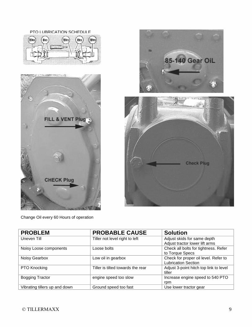
PTO LUBRICATION SCHEDULE
Change Oil every 60 Hours of operation
PROBLEM PROBABLE CAUSE Solution Uneven Till Tiller not level right to left Adjust skids for same depth
Adjust tractor lower lift arms Noisy Loose components Loose bolts Check all bolts for tightness. Refer
to Torque Specs Noisy Gearbox Low oil in gearbox Check for proper oil level. Refer to
Lubrication Section PTO Knocking Tiller is tilted towards the rear Adjust 3-point hitch top link to level
tiller Bogging Tractor engine speed too slow Increase engine speed to 540 PTO
rpm Vibrating tillers up and down Ground speed too fast Use lower tractor gear

© TILLERMAXX 10
MR TILLER SERIES
PARTS
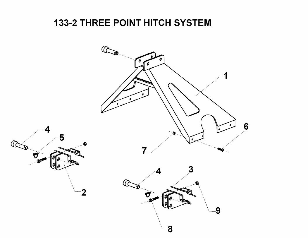
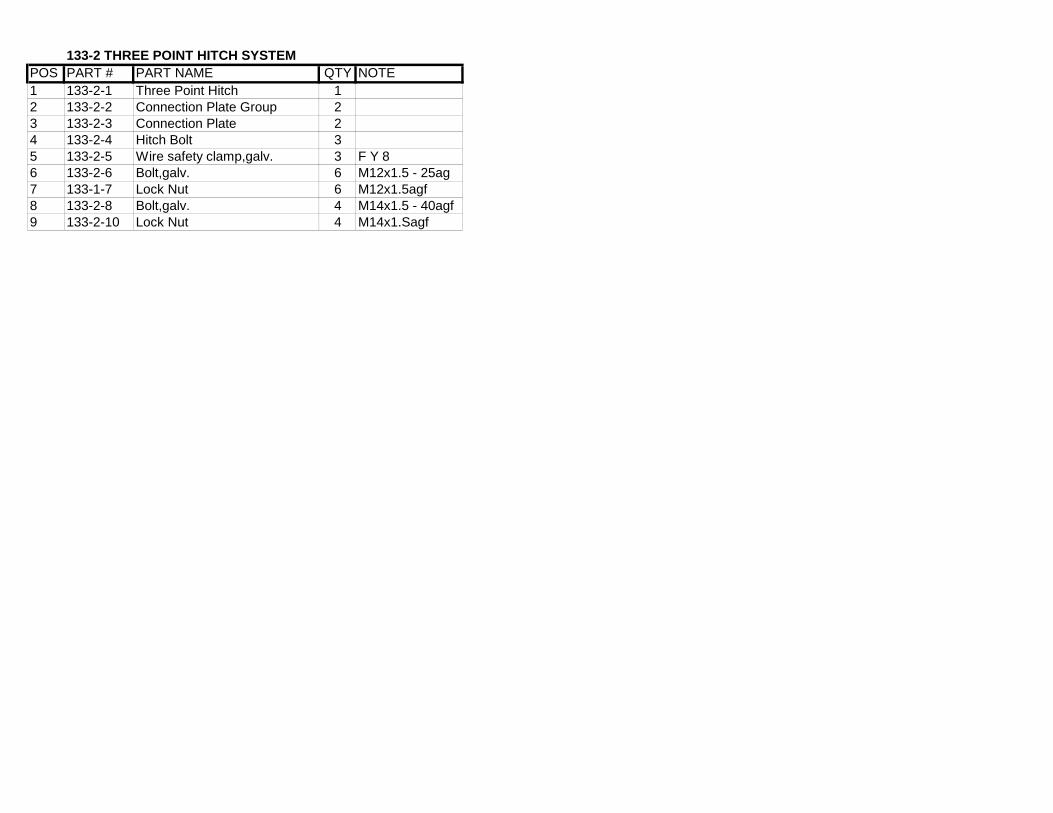
133-2 THREE POINT HITCH SYSTEMPOS PART # PART NAME QTY NOTE1 133-2-1 Three Point Hitch 12 133-2-2 Connection Plate Group 23 133-2-3 Connection Plate 24 133-2-4 Hitch Bolt 35 133-2-5 Wire safety clamp,galv. 3 F Y 86 133-2-6 Bolt,galv. 6 M12x1.5 - 25ag7 133-1-7 Lock Nut 6 M12x1.5agf8 133-2-8 Bolt,galv. 4 M14x1.5 - 40agf9 133-2-10 Lock Nut 4 M14x1.Sagf


133-3 GEAR BOX MR TillersPOS PART # PART NAME QTY INSTRUCTION1 133-3-1-1 Gear-box pipe T-MIR-140 11 133-3-1-2 Gear-box pipe T-MR-160 12 133-3-2-1 Spindle T-MR-140 12 133-3-2-2 Spindle T-MR-160 13 133-3-3 Bearing 2 R63084 133-3-4 Felt 1 K40x80x105 133-3-5 Uppergear 16 133-3-6 Shim 1 S 140x50x17 133-3-7 Spindle elastic ring 1 DS 358 133-3-8 Pinion 19 133-3-9 Spindle elastic ring 2 DS 4010 133-3-10 Shim 6 SI 40x50x0.511 133-3-11 Seal I Karton12 133-3-12 Gearbox 113 133-3-13 Spindle gear 114 133-3-14 Bearing 1 R620715 133-3-15 Shim 1 SI 70x85x0,516 133-3-16 Elasticring 1 IS 7217 133-3-17 Bearing I R620918 133-3-18 Shim I SI 60x70x0,519 133-3-19 Elasticring - 1 IS 8520 133-3-20 Seal 1 K35x72x1021 133-3-21 Seal 1 K35x85x1022 133-3-22 Oil filling plug 423 133-3-23 Oil plug 124 133-3-24 Chain connection plate 125 133-3-25 Skafleks 2Ogr SF 2026 133-3-26 Hexagonal bolt,galv 6 M10x1.5-20 ag27 133-3-27 Gear-box connection plate 128 133-3-28 Hexagonal bolt,galv 4 M12x1,5-20 ag29 133-3-29 Hexagonal bolt,galv 2 M12x1,5-30ag30 133-3-30 Hexagonal security nut,galv. 2 M12x1,5agf
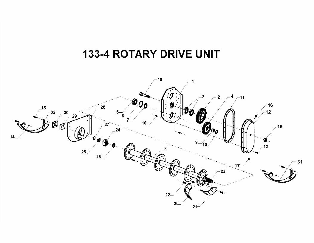

133-4 ROTARY CULTIVATOR UNITPOS PART # PART NAME QTY NOTE
1 133-4-1 Side base 12 133-4-2 Middle gear 1 13 133-4-3 Bearing 2 R60094 133-4-4 Bottom gear 15 133-4-5 Bearing 1 R 62096 133-4-6 Elastic ring 1 IS 857 133-4-7 Seal 1 K45x72x108 133-4-8-1 Roller T-MR-145 18 133-4-8-2 Roller T-MR-160 19 133-4-9 Nut 1 M35x1,5
10 133-4-10 Safety plate 1 As 3511 133-4-11 Seal for gear-box cover 112 1334-12 Gear-box cover 113 133-4-13 Hexagonal bolt,galv. 17 M81,5-2014 133-4-14 Hexagonal-bolt,galv. 12 M10xl,5-25 ag15 133-4-15 Hexagonalsecuritynut 12 M10x1,5agf16 133-4-16 Oil filling plug 1 KT R 1/2�17 133-4-17 Oil plug 1 KT R1/2�18 133-4-18 Hexagonal bolt,galv. 1 M24x3-90 ag19 133-4-19 Lock Nut 1 M24x3ag20 133-4-20-1 Knife (right) T-MR-140 1820 133-4-20-1 Knife (right) T-MR-160 2120 133-4-20-1 Knife (right) T-MR-175 2421 133-4-21-1 Knife (left) T-MR-140 1821 133-4-21-1 Knife(left)T-MR-160 2121 133-4-21-1 Knife (left) T-MR-175 2422 133-4-22-1 Hex bolt,galv.T-MR-140 72 M12x1,5-35 ag22 133-4-22-1 Hex bolt,galv.T-MR-160 84 M12x1,5-35 ag23 133-4-22-2 Hex bolt,galv.T-MR-175 96 M12x1,5-35 ag23 133-4-23-1 Hex security nut T-MR-140 72 M12x1,5 agf23 133-4-23-1 Hex, security nut T-MR-160 84 M12x1,5 agf23 133-4-23-1 Hex security nut T-MR-175 96 M12x1,5 agf24 133-4-24 Bearing housing 125 133-4-25 Bearing 1 R 620626 133-4-26 Seal 1 K45x58x1027 133-4-27 Spindle elastic ring 1 DS 3028 133-4-28 Roller connection plate 129 133-4-29 Seal for costing protection cove 130 133-4-30 Protection lid 131 133-4-31 Skid (right) 132 133-4-32 Skid (Ieft) 1

SR TILLERS
185 & 210
PARTS
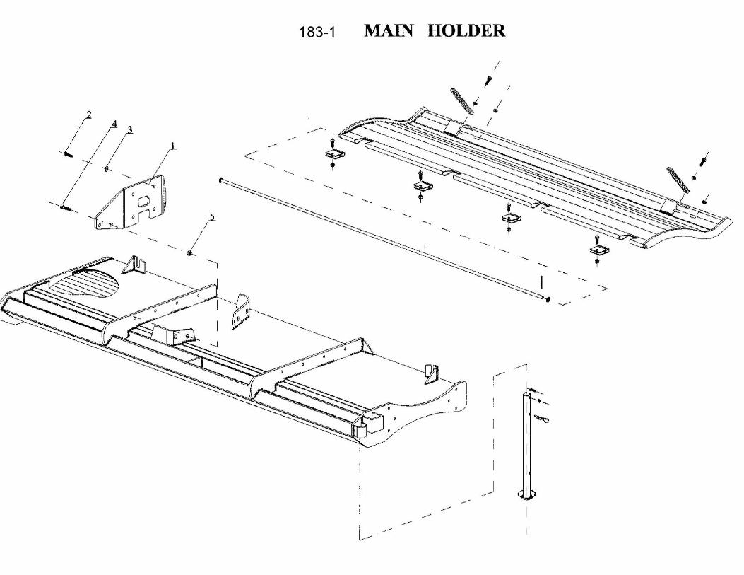
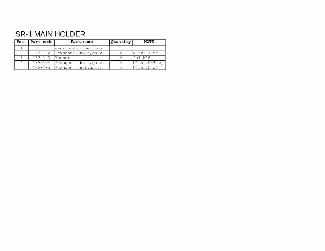
SR-1 MAIN HOLDERPos. Part code Part name Quantity NOTE
1 183-1-1 Gear box connection 12 183-1-2 Hexagonal bolt,galv. 4 M16x2-30ag3 183-1-3 Washer 4 Pul_M164 183-1-4 Hexagonal bolt,galv. 4 M12x1.5-30ag5 183-1-5 Hexagonal nut,galv. 4 M12x1.5agf

SR-2 THREE POINT HITCH SYSTEMPos. Part code Part name Amount NOTE
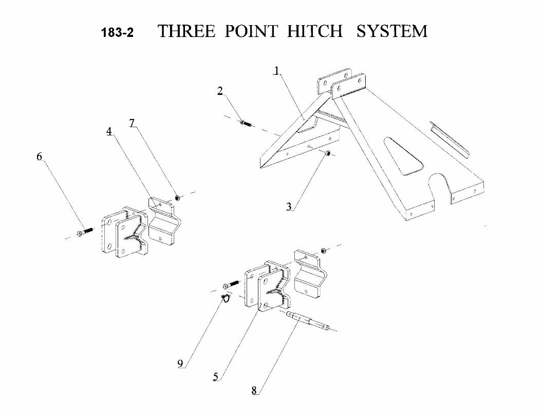
1 183-2-1 Three point hitch 12 183-2-2 Hexagonal bolt,galv. 8 M12x1.5-30ag3 183-2-3 Hexagonal security nut,galv. 8 M12x1.5agf4 183-2-4 Bottom connection plate 25 183-2-5 Bottom connection plate 26 183-2-6 Hexagonal bolt,galv. 4 M14x2-70ag7 183-2-7 Hexagonal security nut,galv. 4 M14x2agf8 183-2-8 Bottom bolt,galv. 29 183-2-9 Safety pin,galv. 2 FY_9.5-g

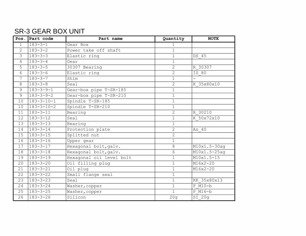
SR-3 GEAR BOX UNITPos. Part code Part name Quantity NOTE1 183-3-1 Gear Box 12 183-3-2 Power take off shaft 13 183-3-3 Elastic ring 1 DS_454 183-3-4 Gear 15 183-3-5 30307 Bearing 2 R_303076 183-3-6 Elastic ring 2 IS_807 183-3-7 Shim 1 -8 183-3-8 Seal 2 K_35x80x109 183-3-9-1 Gear-box pipe T-SR-185 19 183-3-9-2 Gear-box pipe T-SR-210 110 183-3-10-1 Spindle T-SR-185 110 183-3-10-2 Spindle T-SR-210 111 183-3-11 Bearing 2 R_3021012 183-3-12 Seal 1 K_50x72x1013 183-3-13 Bearing 114 183-3-14 Protection plate 2 As_4015 183-3-15 Splitted nut 216 183-3-16 Upper gear 117 183-3-17 Hexagonal bolt,galv. 8 M10x1.5-30ag18 183-3-18 Hexagonal bolt,galv. 6 M10x1.5-25ag19 183-3-19 Hexagonal oil level bolt 1 M10x1.5-1520 183-3-20 Oil filling plug 1 M16x2-2021 183-3-21 Oil plug 1 M16x2-2022 183-3-22 Small flange seal 123 183-3-23 Seal 1 KK_35x80x1324 183-3-24 Washer,copper 1 P_M10-b25 183-3-25 Washer,copper 1 P_M16-b26 183-3-26 Silicon 20g SI_20g
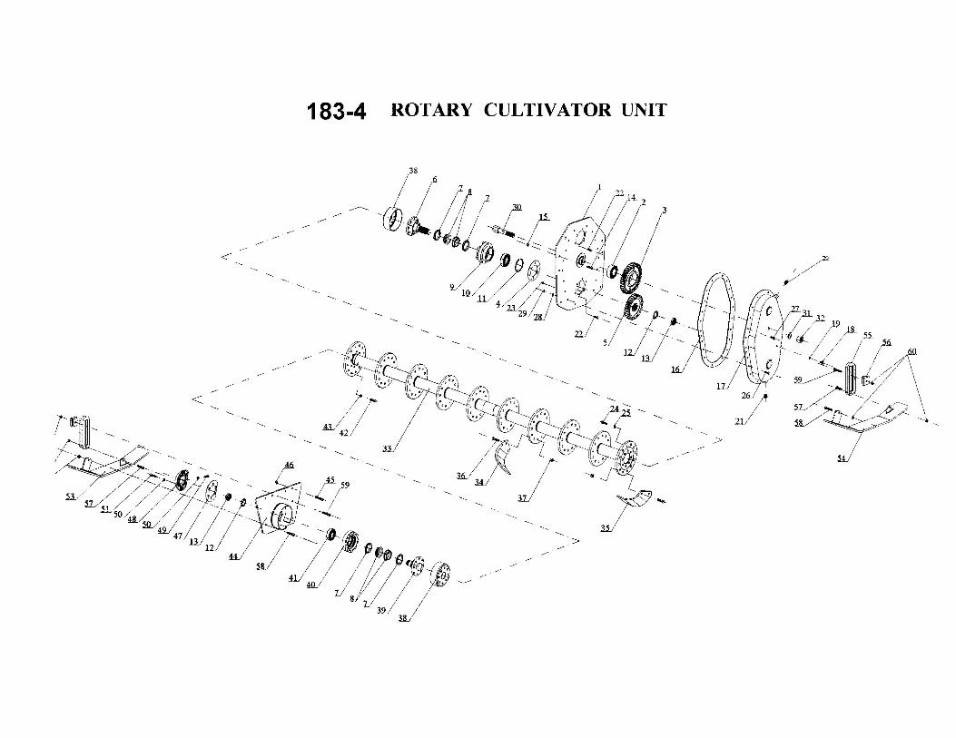
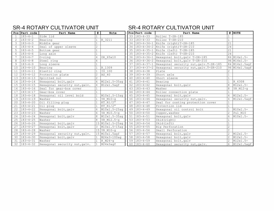
SR-4 ROTARY CULTIVATOR UNIT SR-4 ROTARY CULTIVATOR UNITPos Part code Part Name # Note Pos Part code Part Name # NOTE1 183-4-1 Side lid 1 33 183-4-33 Roller T-SR-185 12 183-4-2 Bearing 1 R_3211 33 183-4-33 Roller T-SR-210 13 183-4-3 Middle gear 1 34 183-4-34-1 Knife (right)T-SR-185 214 183-4-4 Seal of upper sleeve 2 34 183-4-34-2 Knife (right)T-SR-210 245 183-4-5 Bottom gear 1 35 183-4-35-1 Knife (left) T-SR-185 216 183-4-6 Long axle 1 35 183-4-35-2 Knife (left) T-SR-210 247 183-4-7 O-ring 4 OR_65x10 36 183-4-36-1 Hexagonal bolt,galv T-SR-185 84 M14x1.5-8 183-4-8 Steel ring 4 36 183-4-36-2 Hexagonal bolt,galv T-SR-210 96 M14x1.5-9 183-4-9 Long sleeve 1 37 183-4-37-1 Hexagonal security nut,galv.T-SR-185 84 M14x1.5agf10 183-4-10 Bearing 1 R_1309 37 183-4-37-2 Hexagonal security nut,galv.T-SR-210 96 M14x1.5agf11 183-4-11 Elastic ring 1 İS_100 38 183-4-38 Plate 212 183-4-12 Protection plate 2 AS_40 39 183-4-39 Short axle 113 183-4-13 Splitted nut 2 40 183-4-40 Short sleeve 114 183-4-14 Hexagonal bolt,galv 4 M12x1.5-35ag 41 183-4-41 Bearing 1 R_630815 183-4-15 Hexagonal security nut,galv. 4 M12x1.5agf 42 183-4-42 Hexagonal bolt,galv 8 M12x1.5-16 183-4-16 Seal for gear-box cover 1 43 183-4-43 Washer 8 YR_M12-g17 183-4-17 Gear-box cover 1 44 183-4-44 Roller connection plate 118 183-4-18 Hexagonal oil level bold 1 M10x1.5-15ag 45 183-4-45 Hexagonal bolt,galv 4 M12x1.5-19 183-4-19 Washer 1 YR_M10-g 46 183-4-46 Hexagonal security nut,galv. 4 M12x1.5agf20 183-4-20 Oil filling plug 1 KT_R1/2� 47 183-4-47 Seal for costing protection cover 121 183-4-21 Oil plug 1 KT_R1/2� 48 183-4-48 Protection lid 122 183-4-22 Hexagonal bolt,galv 6 M10x1.5-25ag 49 183-4-49 Hexagonal oil control bolt 1 M10x1.5-23 183-4-23 Washer 6 YR_M10.5-g 50 183-4-50 Copper,washer 2 Pul_M1024 183-4-24 Hexagonal bolt,galv 8 M12x1.5-35ag 51 183-4-51 Hexagonal bolt,galv 6 M10x1.5-25 183-4-25 Washer 8 YR_M12.5-g 53 183-4-53 Skid(right) 126 183-4-26 Hexagonal bolt,galv 15 M10x1.5-25ag 54 183-4-54 Skid(left) 127 183-4-27 Hexagonal bolt,galv 3 M10x1.5-15ag 55 183-4-55 Big Perforation 228 183-4-28 Washer 15 YR_M10-g 56 183-4-56 Small Perforation 229 183-4-29 Hexagonal security nut,galv. 15 M10x1.5agf 57 183-4-57 Hexagonal bolt,galv 2 M12x1.5-30 183-4-30 Hexagonal bolt,galv 1 M24x3-100ag 58 183-4-58 Hexagonal bolt,galv 2 M12x1.5-31 183-4-31 Washer 1 R_M24-g 59 183-4-59 Hexagonal bolt,galv 2 M12x1.5-32 183-4-32 Hexagonal security nut,galv. 1 M24x3agf 60 183-4-60 Hexagonal security nut,galv. 6 M12x1.5agf

SR TILLERS
240
PARTS
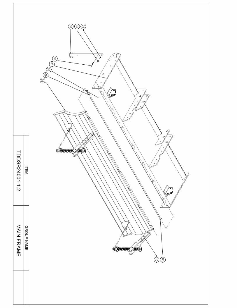
SR-240 ROTARY TILLERS FIXED POSITION-240 CM
ITEM TDDSR24001-1.2
GROUP
MAIN FRAME
1
NO QTY DESCRIPTION TECH.DRW.NUMBER DETAILS
01 1 Frame TDDSR24001-1.2.1
02 1 Rear Lid TDDSR24001-1.2.2
03 1 Lid Pin TDDSR24001-1.2.3
04 1 Nut SOM-AKS-M8x1,25-8,8 M8x1,25-8,8
05 1 Bolt CIV-M8x1,25x20-8.8 M8x1,25x20-8.8
06 1 Support Leg T-CDSR-210-YH9DOZA- 1.2.3
07 1 Hair Pin FIRKETE-MAS-Ø6 Ø6
08 1 Split Pin GUP-5x40 DIN 94 5x40 DIN 94
09 3 Washer RON-DUZ-M14
10 2 Tension Mechanism Assembly TRT210D8SA-1.2.13

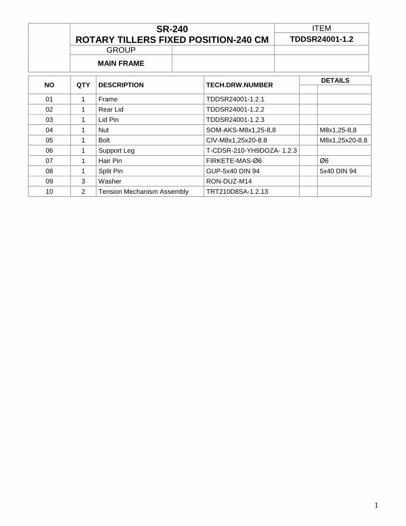
T-SR-240 ROTARY TILLERS FIXED POSITION-240 CM
ITEM TSR240010O-1.1
GROUP
1
NO QTY DESCRIPTION TECH.DRW.NUMBER DETAILS
01 1 Three Point Hitch TSR240010O-1.1.1
02 1 Top Link Pin TSR240010O-1.1.2
03 1 Safety Pin PIM-MAS-ARM Ø8 PIM-MAŞ-ARM Ø8
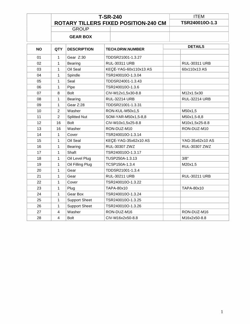
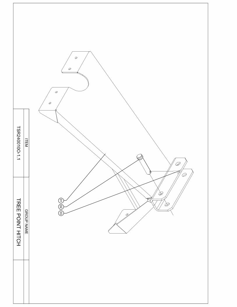
T-SR-240 ROTARY TILLERS FIXED POSITION-240 CM
ITEM TSR240010O-1.3
GROUP
GEAR BOX
1
NO QTY DESCRIPTION TECH.DRW.NUMBER DETAILS
01 1 Gear Z:30 TDDSR21001-1.3.27
02 1 Bearing RUL-30311 URB RUL-30311 URB
03 1 Oil Seal KEÇE-YAG-60x110x13 AS 60x110x13 AS
04 1 Spindle TSR240010O-1.3.04
05 1 Seal TDDSR24001-1.3.43
06 1 Pipe TSR240010O-1.3.6
07 8 Bolt CIV-M12x1,5x30-8.8 M12x1.5x30
08 1 Bearing RUL-32214 URB RUL-32214 URB
09 1 Gear Z:28 TDDSR21001-1.3.31
10 2 Washer RON-KUL-M50x1,5 M50x1,5
11 2 Splitted Nut SOM-YAR-M50x1,5-8,8 M50x1,5-8,8
12 16 Bolt CIV-M10x1,5x25-8.8 M10x1,5x25-8.8
13 16 Washer RON-DUZ-M10 RON-DUZ-M10
14 1 Cover TSR240010O-1.3.14
15 1 Oil Seal KEÇE-YAG-35x62x10 AS YAG-35x62x10 AS
16 1 Bearing RUL-30307 ZWZ RUL-30307 ZWZ
17 1 Shaft TSR240010O-1.3.17
18 1 Oil Level Plug TUSP250A-1.3.13 3/8''
19 1 Oil Filling Plug TCSP150A-1.3.4 M20x1.5
20 1 Gear TDDSR21001-1.3.4
21 1 Gear RUL-30211 URB RUL-30211 URB
22 1 Cover TSR240010O-1.3.22
23 1 Plug TAPA-80x10 TAPA-80x10
24 1 Gear Box TSR240010O-1.3.24
25 1 Support Sheet TSR240010O-1.3.25
26 1 Support Sheet TSR240010O-1.3.26
27 4 Washer RON-DUZ-M16 RON-DUZ-M16
28 4 Bolt CIV-M16x2x50-8.8 M16x2x50-8.8
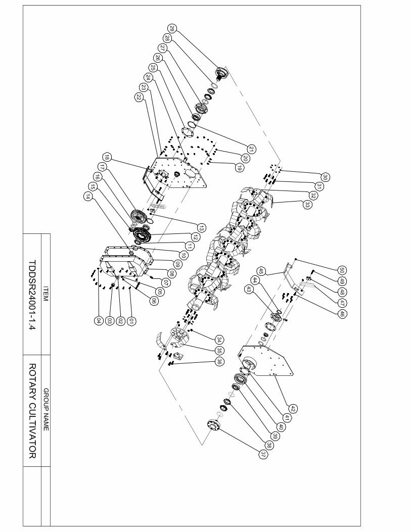

T-SR-240 ROTARY TILLERS FIXED POSITION-240 CM
ITEM TDDSR24001-1.4
GROUP
ROTARY CULTIVATOR
1
NO QTY DESCRIPTION TECH.DRW.NUMBER DETAILS
01 22 Bolt CIV-M10x1,5x25-8.8 M10x1,5x25-8.8
02 1 Washer RON-DUZ-M30 M30
03 1 Nut SOM-AKS-M30x3,5 8,8 M30x3,5 8,8
04 1 Oil Level Plug T-USP-250-0-1.3.13 G 3/8''
05 2 Washer RON-BAK-M10 M10
06 2 Bolt CIV-M10x1,5x16-8.8 M10x1,5x16-8.8
07 1 Oil Filling Plug T-USP-250-0-1.3.14 G 3/8''
08 1 Gear Box Cover TDDSR21004-1.4.26
09 1 Seal TDDSR21004-1.4.25
10 2 Snap Ring SEG-DIN472Ø100x3-CK75 DIN472Ø100x3-CK75
11 2 Bearing RUL-6211 ORS 6211 ORS
12 1 Gear Z: 38 TDDSR21004-1.4.3
13 2 Nut SOMFIB-AKS-M12x1,5 M12x1.5
14 1 Shim TDDSR21004-1.4.18
15 2 Nut SOM-YAR-M50x1,5-8,8 M50x1,5-8,8
16 4 Aspelya RON-KUL-M50x1,5 M50x1,5
17 1 Gear Z:34 TDDSR24001-1.4.17
18 1 Skid Left TDDSR24001-1.4.18
19 22 Spring Washer RON-YAY-M10 M10
20 22 Nut SOMFIB-AKS-M10x1,5 M10x1.5
21 1 Snap Ring SEG-DIN472Ø120x4-CK75 DIN472Ø120x4-CK75
22 1 Left Side Pannel TDDSR24001-1.4.22
23 2 Bolt CIV-M12x1,75x35-8.8 M12x1,75x35-8.8
24 1 Bolt SAP-M30x3.5x140x50-8.8 M30x3.5x140x50-8.8
25 1 Shim TDDSR24001-1.4.25
26 1 Bearing RUL-1311 ZWZ 1311 ZWZ
27 1 Housing TDDSR24001-1.4.27
28 4 O-Ring O-RING80x10 NBR 80x10
29 1 Hub TDDSR24001-1.4.29
30 16 Spring Washer RON-YAY-M12 M12
31 22 Bolt CIV-M12x1,5x35-8.8 M12x1,5x35-8.8
32 1 Rotor TDDSR24001-1.4.32
T-SR-240 ROTARY TILLERS FIXED POSITION-240 CM
ITEM TDDSR24001-1.4
GROUP
ROTARY CULTIVATOR
2
NO QTY DESCRIPTION TECH.DRW.NUMBER DETAILS
33 24 Blade Left TDDSR24001-1.4.33 34 108 Nut SOMFIB-AKS-M14x1,5 M14x1.5 35 24 Blade Right TDDSR24001-1.4.35 36 108 Bolt CIV-M14x1,5x40-8.8 M14x1,5x40-8.8 37 1 Stub Axle TDDSR24001-1.4.37 38 4 Shim TDDSR24001-1.4.38 39 1 Bearing RUL-6310 C3 ORS 6310 C3 ORS 40 1 Housing TDDSR24001-1.4.40 41 1 Housing Seal TDDSR24001-1.4.41 42 1 Right Side Pannel TDDSR24001-1.4.42 43 1 Cover TDDSR24001-1.4.43 44 1 Plug TAPA-72x7x1 72x7x1 45 1 Skid Right TDDSR24001-1.4.45 46 2 Bolt CIV-M12x1,75x40-8.8 M12x1,75x40-8.8 47 2 Big Perforation TSR14005O-1.4.11 48 2 Small Perforation TSR14005O-1.4.9 49 2 Bolt CIV-M12x1,5x50-8.8 M12x1,5x50-8.8 50 4 Nut SOMFIB-AKS-M12x1,75 M12x1.75
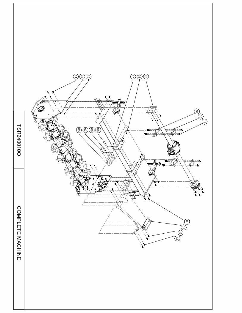

T-SR-240 ROTARY TILLERS FIXED POSITION-240 CM
ITEM TSR240010O
GROUP
COMPLETE MACHINE
1
NO QTY DESCRIPTION TECH.DRW.NUMBER DETAILS
01 1 Three Point Hitch Group TSR240010O-1.1
02 1 Main Holder Group TDDSR24001-1.2
03 1 Gear Box Group TSR240010O-1.3
04 1 Rotary Cultivator Group TDDSR24001-1.4
05 2 Pin TSR240010O-1.5
06 2 Pin Middle TSR240010O-1.6
07 2 Pin Front TSR240010O-1.7
08 2 Pin TDDSR24001-1.1.6
09 8 Cıvata CIV-M14x1,5x40-8.8 M14x1,5x40-8.8
10 8 Nut SOMFIB-AKS-M14x1,5 M14x1.5
11 6 Bolt CIV-M12x1,5x30-8.8 M12x1,5x30-8.8
12 12 Bolt CIV-M12x1,5x40-8.8 M12x1,5x40-8.8
13 10 Bolt CIV-M12x1,5x35-8.8 M12x1,5x35-8.8
14 26 Nut SOMFIB-AKS-M12x1,5 M12x1.5
15 2 Pipe Sheet TDDSR21001-1.16.02
16 2 Support TDDSR21001- 1.16
17 6 Safety Pin PIM-MAS-ARM Ø8 PIM-MAS-ARM Ø8

LIMITED WARRANTY Tillermaxx/Minos provides a limited warranty on this tiller against material defects in the parts and workmanship for the period of one year from the date of purchase by the original purchaser. This limited warranty is only extended to the original purchaser and is non-transferable. The warranty is restricted to 90 days for commercial applications, golf courses, and municipalities and for rental purposes. This limited warranty covers all material of the tiller, with the exception of the normal wear items, including but not restricted to, blades. This warranty does not cover any cleaning, repair labor or transportation to and from the dealer and or transportation cost of the repair parts. The Tillermaxx/Minos will provide at no charge a replacement part for any item it deems defective. The Tillermaxx/Minos has the right to inspect the part before committing to replace it. This warranty is voided in the event the tiller has been used in applications not recommended, accidental damage, and improper operation, incorrect or lack of maintenance and/or for a machine that has been modified by sources not authorized by Tillermaxx/Minos. A claim needs to be addressed to the dealer, who will contact and place the warranty claim with Tillermaxx/Minos. This warranty shall not be interpreted to render Tillermaxx/Minos liable for damages of any kind, direct, consequential, or contingent to property. Tillermaxx/Minos is neither liable for any damage beyond its control. This warranty does not cover loss of income, rental, penalties, legal action, and labor for any reason. No other warranty of any kind whatsoever, express or implied, is made with retrospect to this sale. All implied warranties of merchantability and fitness for a particular purpose, which exceed the obligations set forth in this warranty, are disclaimed and excluded. Tillermaxx/Minos reserves the right to change designs and drawings without notice.