title: a/c blower motor malfunction …v6mr2.info/toyota/lexus es300 1997 workshop manual...lexus...
TRANSCRIPT

Lexus Supports ASE Certification Page 1 of 2
Title:
A/C BLOWER MOTOR MALFUNCTIONModels:
’97 ES 300Technical Service
Information BulletinJuly 17, 1998
AC
002–98
A Malfunction of the A/C blower motor may be caused by water intrusion into the blowerunit due to a poor seal between the windshield and the cowl top ventilation louver.
EPT SealerCowl TopVentilatorLouver
Water Entry & FlowDepicted by Arrow Windshield
Glass
A–A’ CrossSection
A
A’
To prevent this, the amount of caulking sponge sealant (EPT Sealer) applied behind thecowl top ventilation louver has been increased. In addition, the shape of the louver hasbeen changed as shown in the illustrations below.
EPT Sealer
7 mm
Old Style A–A’ CrossSection
New Style A–A’ CrossSection
DeeperLouver
10 mm
LouverDepth
1997 model year ES 300s produced before JT8BF22G*W0096000 at Tsutsumi plant or before JT8BF22G*W5022600 at Kyushu plant.
OLD PART NUMBER NEW PART NUMBER PART NAME
55781–33140 Same Lower Cowl Top Ventilator, RH
55782–33140 Same Lower Cowl Top Ventilator, LH
HE
AT
ING
& A
IR C
ON
DIT
ION
ING
Introduction
AffectedVehicles
PartsInformation
A/C BLOWER MOTOR MALFUNCTION – AC002–98 July 17, 1998
Page 2 of 2
OP CODE DESCRIPTION TIME OPN T1 T2
EL8001 R&R Blower Motor 0.6 87103–44020 66 83
Applicable Warranty*:This repair is covered under the Lexus Basic Warranty. This warranty is in effect for48 months or 50,000 miles, whichever occurs first, from the vehicle’s in–service date.
* Warranty application is limited to correction of a problem based upon a customer’s complaint.
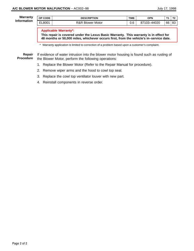
If evidence of water intrusion into the blower motor housing is found such as rusting ofthe Blower Motor, perform the following operations:
1. Replace the Blower Motor (Refer to the Repair Manual for procedure).
2. Remove wiper arms and the hood to cowl top seal.
3. Replace the cowl top ventilator louver with new part.
4. Reinstall components in reverse order.
WarrantyInformation
RepairProcedure

Lexus Supports ASE Certification Page 1 of 12
Title:
SENSOR INSPECTION FOR AIR
CONDITIONING SYSTEMModels:
’90 – Current All Models
Technical ServiceInformation Bulletin
December 16, 2004
AC
005-04
This service bulletin contains inspection procedures to more precisely confirm properoperation of the following temperature sensors of the air conditioning system. Follow theprocedures in this service bulletin when inspecting these sensors. These contents will bereflected in future repair manuals.
Room Temperature Sensor
Ambient Temperature Sensor
Air Duct Sensor
Evaporator Temperature Sensor
Solar Sensor
Room Humidity Sensor
All 1990 – Current model year Lexus vehicles.
OP CODE DESCRIPTION TIME OFP T1 T2
N/A Not Applicable to Warranty – – – –
HE
AT
ING
& A
IR C
ON
DIT
ION
ING
Introduction
ApplicableVehicles
WarrantyInformation

SENSOR INSPECTION FOR AIR CONDITIONING SYSTEM – AC005-04 December 16, 2004
Page 2 of 12
1. Inspect Room Temperature Sensor.
A. Measure the sensor resistance.
Resistance Value at 77°F(25°C)
1700 +/– 85Ω
NOTE: Even slightly touching the sensor
may change the resistance value.Be sure to hold the connector ofthe sensor.
When measuring, the sensortemperature must be the same asthe ambient temperature.
HINT:As the temperature increases, theresistance decreases.
TEMPERATURE °F (°C) SPECIFICATION kΩ
50 (10) 3.00 to 3.73
59 (15) 2.45 to 2.88
68 (20) 1.95 to 2.30
77 (25) 1.60 to 1.80
86 (30) 1.28 to 1.47
95 (35) 1.00 to 1.22
104 (40) 0.80 to 1.00
113 (45) 0.65 to 0.85
122 (50) 0.50 to 0.70
131 (55) 0.44 to 0.60
140 (60) 0.36 to 0.50
InspectionProcedure
ResistancekΩ
4.0
3.5
3.0
2.5
2.0
1.5
1.0
0.5
0.032(0)
68(20)
104(40)
140(60)
Temperature °F (°C)
Max
Min

SENSOR INSPECTION FOR AIR CONDITIONING SYSTEM – AC005-04 December 16, 2004
Page 3 of 12
2. Inspect Ambient Temperature Sensor.
A. Measure the sensor resistanceaccording to the selected graph(specification).
Resistance Value at 77°F(25°C)
1700 +/– 85Ω
NOTE: Even slightly touching the sensor
may change the resistance value.Be sure to hold the connector ofthe sensor.
When measuring, the sensortemperature must be the same asthe ambient temperature.
HINT:As the temperature increases, theresistance decreases.
TEMPERATURE °F (°C) SPECIFICATION kΩ
50 (10) 3.00 to 3.73
59 (15) 2.45 to 2.88
68 (20) 1.95 to 2.30
77 (25) 1.60 to 1.80
86 (30) 1.28 to 1.47
95 (35) 1.00 to 1.22
104 (40) 0.80 to 1.00
113 (45) 0.65 to 0.85
122 (50) 0.50 to 0.70
131 (55) 0.44 to 0.60
140 (60) 0.36 to 0.50
InspectionProcedure(Continued)
ResistancekΩ
4.0
3.5
3.0
2.5
2.0
1.5
1.0
0.5
0.032(0)
68(20)
104(40)
140(60)
Temperature °F (°C)
Max
Min

SENSOR INSPECTION FOR AIR CONDITIONING SYSTEM – AC005-04 December 16, 2004
Page 4 of 12
3. Inspect Air Duct Sensor.
A. Measure the sensor resistanceaccording to the table and graph (specification).
NOTE: Even slightly touching the sensor
may change the resistance value.Be sure to hold the connector ofthe sensor.
When measuring, the sensortemperature must be the same asthe ambient temperature.
HINT:As the temperature increases, theresistance decreases.
TEMPERATURE °F (°C) SPECIFICATION kΩ
50 (10) 9.48 to 10.49
59 (15) 7.50 to 8.28
68 (20) 5.95 to 6.57
77 (25) 4.77 to 5.25
86 (30) 3.85 to 4.21
95 (35) 3.12 to 3.40
104 (40) 2.53 to 2.79
113 (45) 2.06 to 2.30
122 (50) 1.69 to 1.91
131 (55) 1.39 to 1.59
140 (60) 1.15 to 1.33
InspectionProcedure(Continued)
ResistancekΩ
15.0
10.0
5.0
0.032(0)
68(20)
104(40)
140(60)
Temperature °F (°C)
Max
Min
176(80)

SENSOR INSPECTION FOR AIR CONDITIONING SYSTEM – AC005-04 December 16, 2004
Page 5 of 12
4. Inspect Evaporator Temperature Sensor.
Select the appropriate graph (specification) using the following table.
NOTE:Please inspect the sensors for model years not indicated by this bulletin, according tothe instructions in the applicable repair manual.
MODEL MODEL YEAR COMMENTS PART NUMBER GRAPH
ES 300 1992 – 2001 88625–33070 2
ES 300/3302002 – 2003 88625–17130 2
ES 300/3302003 88625–33170 3
GS 300 1993 – 1997 88625–3A020 2
GS 300/400/430 1998 – 2002 88625–3A120 2
GX 470 2003 2005Thermistor No. 1 88625–35050 3
GX 470 2003 – 2005Thermistor No. 2 88625–16210 2
IS 300 2000 – 2001 88625–48010 2
1990 – 1992 88625–32040 2
LS 400 1993 – 1994 88625–50100 2
1995 – 2000 88625–50140 2
LS 430 2001 – 2005 88625–50160 2
LX 450 1996 – 1997 88625–60060 2
1998 – 2000 Thermistor No. 2 88625–60140 2
LX 470 1998 – 2002 Thermistor No. 1 88625–60130 2
2003 – 2005 88625–47011 2
RX 300 1998 – 2003 88625–48010 2
2004 CBU 88625–48050 1
RX 3302004 2005
CBU88625 48060 32004 – 2005
NAP88625–48060 3
SC 300/400 1991 – 2000 88625–32040 2
InspectionProcedure(Continued)

SENSOR INSPECTION FOR AIR CONDITIONING SYSTEM – AC005-04 December 16, 2004
Page 6 of 12
A. Measure the sensor resistance according to the selected graph (specification).
NOTE: Even slightly touching the sensor may change the resistance value.
Be sure to hold the connector of the sensor. When measuring, the sensor temperature must be the same as the
ambient temperature.
HINT:As the temperature increases, the resistance decreases.
Graph 1:
TEMPERATURE °F (°C) SPECIFICATION kΩ
14 (–10) 7.30 to 9.10
23 (–5) 5.65 to 6.95
32 (0) 4.40 to 5.35
41 (5) 3.40 to 4.15
50 (10) 2.70 to 3.25
59 (15) 2.14 to 2.58
68 (20) 1.71 to 2.05
77 (25) 1.38 to 1.64
86 (30) 1.11 to 1.32
Graph 2:
TEMPERATURE °F (°C) SPECIFICATION kΩ
14 (–10) 7.40 to 9.20
23 (–5) 5.65 to 7.00
32 (0) 4.35 to 5.40
41 (5) 3.40 to 4.20
50 (10) 2.68 to 3.30
59 (15) 2.10 to 2.60
68 (20) 1.66 to 2.10
77 (25) 1.32 to 1.66
86 (30) 1.05 to 1.35
InspectionProcedure(Continued)
ResistancekΩ 12.0
3.02.0
0.032(0)
68(20)
104(40)
Temperature °F (°C)
MaxMin1.0
4.0
8.07.0
5.06.0
9.010.011.0
–4(–20)
32(0)
68(20)
104(40)
–4(–20)
ResistancekΩ
3.0
2.0
0.0
Temperature °F (°C)
Max
Min1.0
4.0
8.07.0
5.0
6.0
9.0
10.0

SENSOR INSPECTION FOR AIR CONDITIONING SYSTEM – AC005-04 December 16, 2004
Page 7 of 12
Graph 3:
TEMPERATURE °F (°C) SPECIFICATION kΩ
14 (–10) 8.00 to 10.00
23 (–5) 6.15 to 7.65
32 (0) 4.75 to 5.85
41 (5) 3.70 to 4.55
50 (10) 2.91 to 3.55
59 (15) 2.32 to 2.80
68 (20) 1.85 to 2.22
77 (25) 1.48 to 1.77
86 (30) 1.20 to 1.43
InspectionProcedure(Continued)
32(0)
68(20)
104(40)
–4(–20)
Temperature °F (°C)
ResistancekΩ 12.0
3.02.0
0.0
MaxMin1.0
4.0
8.07.0
5.06.0
9.010.011.0

SENSOR INSPECTION FOR AIR CONDITIONING SYSTEM – AC005-04 December 16, 2004
Page 8 of 12
5. Inspect Solar Sensor.
Four types of solar sensors are used on Lexus vehicles depending on the vehiclespecifications. The inspection procedure for each type of sensor differs from theothers. Select the appropriate inspection procedure from the table below according tovehicle specifications and perform the inspection.
EQUIPPED WITH AUTOMATICLIGHT CONTROL SYSTEM
A/C SYSTEM WITH RIGHT/LEFTINDEPENDENT TEMPERATURE CONTROL
INSPECTIONPROCEDURE
No No A
No Yes B
Yes Yes C
Yes No D
Procedure A:
a. Disconnect the solar sensor connector.
b. Measure the resistance betweenterminals 1 and 2 of the solarsensor under thefollowing conditions:
Cover the sensor with a clothto avoid direct light.
Expose the sensor to lightfrom a distance of 300 mm(11.81 in.) or less with aninspection light.
NOTE: Terminal 1 of the sensor is always on
the right, when the lock is facing up. When using an analog tester, connect
the positive (+) lead to terminal 2 andnegative (–) lead to terminal 1 of thesolar sensor.
HINT:If the light is weak, the sensor may not react. Be sure to use an incandescent light foran inspection light.
Standard:CONDITION SPECIFICATION
When the sensor is covered with a cloth(to avoid direct light)
Infinite ohms
When the sensor is exposed to light Less than infinite resistance
InspectionProcedure(Continued)
Lock

SENSOR INSPECTION FOR AIR CONDITIONING SYSTEM – AC005-04 December 16, 2004
Page 9 of 12
Procedure B:
a. Disconnect the solar sensor connector.
b. Measure the resistance betweenterminals 2 and 3 of the solarsensor under thefollowing conditions:
Cover the sensor with a clothto avoid direct light.
Expose the sensor to lightfrom a distance of 300 mm(11.81 in.) or less with aninspection light.
NOTE:When using an analog tester, connectthe positive (+) lead to terminal 3 andnegative (–) lead to terminal 2 of thesolar sensor.
HINT:If the light is weak, the sensor may not react. Be sure to use an incandescent light foran inspection light.
Standard:CONDITION SPECIFICATION
When the sensor is covered with a cloth(to avoid direct light)
Infinite ohms
When the sensor is exposed to light Less than infinite resistance
InspectionProcedure(Continued)
Lock

SENSOR INSPECTION FOR AIR CONDITIONING SYSTEM – AC005-04 December 16, 2004
Page 10 of 12
Procedure C:
a. Turn the ignition switch ON.
b. Measure the voltage betweenterminals TSR (+) and CLTE (–) of the connector under thefollowing conditions:
Cover the sensor with a clothto avoid direct light.
Expose the sensor to lightfrom a distance of 300 mm(11.81 in.) or less with aninspection light.
HINT: If the light is weak, the sensor may not react. Be sure to use an incandescent light
for an inspection light. Do not disconnect the solar sensor connector.
Standard:CONDITION SPECIFICATION
When the sensor is covered with a cloth(to avoid direct light)
Below 0.8 V
When the sensor is exposed to light 4.3 +/– 0.3 V
c. Measure the voltage betweenterminals TSL (+) and CLTE (–) of the connector under thefollowing conditions:
Cover the sensor with a clothto avoid direct light.
Expose the sensor to lightfrom a distance of 300 mm(11.81 in.) or less with aninspection light.
HINT: If the light is weak, the sensor may not react. Be sure to use an incandescent light
for an inspection light. Do not disconnect the solar sensor connector.
Standard:CONDITION SPECIFICATION
When the sensor is covered with a cloth(to avoid direct light)
Below 0.8 V
When the sensor is exposed to light 4.3 +/– 0.3 V
InspectionProcedure(Continued)
CLTE
TSR
TSL
CLTE

SENSOR INSPECTION FOR AIR CONDITIONING SYSTEM – AC005-04 December 16, 2004
Page 11 of 12
Procedure D:
a. Turn the ignition switch ON.
b. Using the tester, measure thevoltage between terminalsTSD (+) and CLTE (–) of theconnector under the following conditions:
Cover the sensor with a clothto avoid direct light.
Expose the sensor to lightfrom a distance of 300 mm(11.81 in.) or less with aninspection light.
HINT: If the light is weak, the sensor may not react. Be sure to use an incandescent light
for an inspection light. Do not disconnect the solar sensor connector.
Standard:CONDITION SPECIFICATION
When the sensor is covered with a cloth(to avoid direct light)
Below 0.8 V
When the sensor is exposed to light 4.3 +/– 0.3 V
InspectionProcedure(Continued)
TSD
CLTE

SENSOR INSPECTION FOR AIR CONDITIONING SYSTEM – AC005-04 December 16, 2004
Page 12 of 12
6. Inspect Room Humidity Sensor.
Measure the humidity and outputvoltage of the humidity sensor whenthe sensor is installed on the vehicleand the temperature at the humiditysensor position (room temperaturesensor position) is 77°F (25°C). If the output voltage is within thespecifications according to the graphand table below, the sensor is normal.
HINT:For the inspection procedure of theroom temperature sensor, refer to“Room Temperature Sensor InspectionProcedure” in this bulletin.
A. Turn the ignition switch to the ON position.
B. Measure the voltage betweenterminal VO (3) and GND (2) ofthe room humidity sensor.
C. Measure the humidity and voltagewhen the room temperature(humidity sensor position) is 77°F(25°C). According to the result,determine whether the sensor isnormal or not.
HUMIDITY (% RH)OUTPUT VOLTAGE
AT 77°F (25°C)
10 0.70 to 1.08 V
20 0.72 to 1.57 V
30 1.13 to 1.95 V
40 1.61 to 2.24 V
50 1.99 to 2.46 V
60 2.26 to 2.66 V
70 2.48 to 2.85 V
80 2.68 to 3.04 V
90 2.87 to 3.05 V
InspectionProcedure(Continued)
VO GND
ResistancekΩ 3.50
3.00
2.50
2.00
1.50
1.00
0.50
0.0032(0)
68(20)
104(40)
140(60)
Temperature °F (°C)
Max
Min
176(80)
212(100)

Lexus Supports ASE Certification Page 1 of 1
Title:
LEXUS DINGHY" TOWING GUIDEModels:
All ModelsTechnical Service
Information BulletinMarch 17, 2000
AX
001–00
The following chart indicates which Lexus vehicles can be Dinghy towed (towed with fourwheels on the ground) behind a Motorhome.
CAUTION:Dinghy towing a vehicle behind a Motorhome requires special towing equipment andaccessories. Please see your Motorhome Manufacturer / Service Outlet forrecommended towing equipment.
All Models
YEAR MODELDINGHY TOWABLE SPEED/DISTANCE
YEAR MODELM/T A/T
SPEED/DISTANCELIMITS
1990–2000 LS 400 Not Towable –
1992–2000 SC 400/300 NotTowable
NotTowable
–
1993–2000 GS 400/300 Not Towable –
1992–1998 ES 300 Not Towable –
1999–2000 ES 300 Yes 55 mph / 200 miles
1999–2000 RX 300 2WD Yes 55 mph / 200 miles
1999–2000 RX 300 4WD Yes 55 mph / 200 miles
1996–1997 LX 450 Not Towable –
1998–2000 LX 470 Not Towable –
NOTE:After “Dinghy” Towing, or at the recommended distance limits, let the Engine idle formore than 3 minutes before operating the vehicle or resuming towing.
NOTE:Vehicles that are Dinghy towable will not sustain internal damage to the transmissionor transfer components, as long as speed/distance limits are observed. Thetransmission must be placed in the “neutral” position when Dinghy towing. Dinghytowing these vehicles does not eliminate the possibility of damage to other vehiclesystems (Body, Chassis, Electrical Systems, etc.).
OP CODE DESCRIPTION TIME OPN T1 T2
N/A Not Applicable to Warranty – – – –
AC
CE
SS
OR
IES
Introduction
ApplicableVehicles
WarrantyInformation

Page 1 of 1Lexus Supports ASE Certification
Title:
RETRO-FIT INTERNAL TRUNK
RELEASE KITSModels:
ES 300, GS 400/300, LS 400 & SC 400/300
Technical ServiceInformation Bulletin
May 25, 2001
AX
001-01
TSIB REVISION NOTICE:The parts information updated in this TSIB is red and underlined .
In order to respond to requests of our valued customers, we are offering Retro–FitInternal Trunk Release Kits. These kits allow the trunk to be opened from the inside incase of entrapment.
MODEL MODEL CODE MODEL YEAR # CLAMPS
ES 300VCV10, MCV10 1992 – 1996 4
ES 300MCV20 1997 – 2000 4
GS 300 JZS147 1994 – 1997 4
GS 400/300 UZS160, JZS160 1998 – 2000 4
LS 400UCF10 1993 – 1994 4
LS 400UCF20 1995 – 2000 4
SC 400/300 UZZ30, JZZ31 1992 – 2000 4
PREVIOUS PART NUMBER CURRENT PART NUMBER PART NAME
– 64640–33030 Trunk Release
– 90464–00551 Clamp
– MDC 00237–LUTRI–01 Installation Instructions
Order the appropriate trunk release, at least as many clamps as listed above, and a setof installation instructions. Follow the installation procedure detailed in the installationinstructions. Installation time is 0.7 hours.
OP CODE DESCRIPTION TIME OPN T1 T2
N/A Not Applicable to Warranty – – – –
AC
CE
SS
OR
IES
Introduction
ApplicableVehicles
PartsInformation
InstallationProcedure
WarrantyInformation

Lexus Supports ASE Certification Page 1 of 1
Title:
LEXUS DINGHY" TOWING GUIDEModels:
All ModelsTechnical Service
Information BulletinMarch 19, 1999
AX
003–99
The following chart indicates which Lexus vehicles can be Dinghy towed (towed with fourwheels on the ground) behind a Motorhome.
CAUTION:Dinghy towing a vehicle behind a Motorhome requires special towing equipment andaccessories. Please see your Motorhome Manufacturer / Service Outlet forrecommended towing equipment.
All Models
YEAR MODELDINGHY TOWABLE SPEED/DISTANCE
YEAR MODELM/T A/T
SPEED/DISTANCELIMITS
1990 – 1999 LS 400 Not Towable –
1992 – 1999 SC 300 Not Towable –
1992 – 1999 SC 400 Not Towable –
1993 – 1999 GS 300 Not Towable –
1992 – 1998 ES 300 Not Towable –
1999 ES 300 N/A Yes 55 mph / 200 miles
1996 – 1997 LX 450 Not Towable –
1998 – 1999 LX 470 Not Towable –
1999 RX 300 2WD N/A Yes 55 mph / 200 miles
1999 RX 300 4WD N/A Yes 55 mph / 200 miles
NOTE:After “Dinghy“ Towing, let the Engine idle for more than 3 minutes.
NOTE:Vehicles that are Dinghy towable will not sustain internal damage to the transmissionor transfer components. The transmission must be placed in the “neutral“ positionwhen Dinghy towing. Dinghy towing these vehicles does not eliminate the possibilityof damage to other vehicle systems (Body, Chassis, Electrical Systems, etc.).
OP CODE DESCRIPTION TIME OPN T1 T2
N/A Not Applicable to Warranty – – – –
AC
CE
SS
OR
IES
Introduction
AffectedVehicles
WarrantyInformation
Lexus Supports ASE Certification Page 1 of 5
Title:
SEAT BELT EXTENDERSModels:
All ’94 through ’98 models, and ’99 RX 300Technical Service
Information BulletinApril 24, 1998
BO
001–98
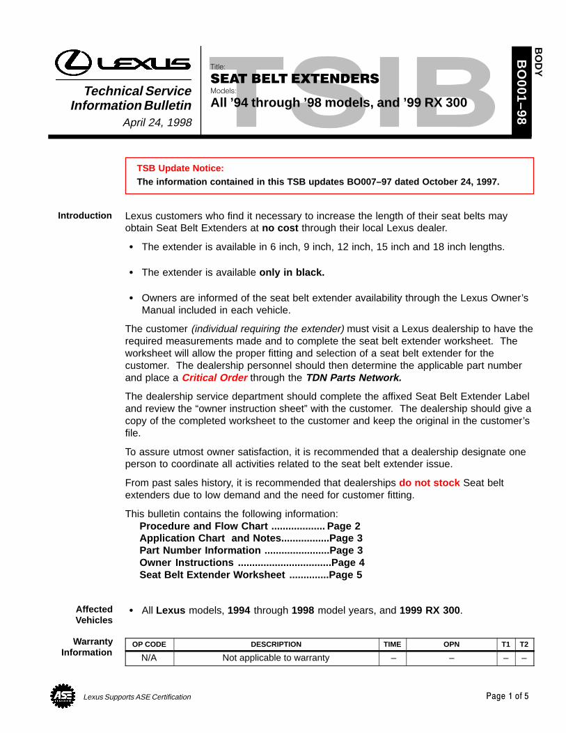
TSB Update Notice:The information contained in this TSB updates BO007–97 dated October 24, 1997.
Lexus customers who find it necessary to increase the length of their seat belts mayobtain Seat Belt Extenders at no cost through their local Lexus dealer.
The extender is available in 6 inch, 9 inch, 12 inch, 15 inch and 18 inch lengths.
The extender is available only in black.
Owners are informed of the seat belt extender availability through the Lexus Owner’sManual included in each vehicle.
The customer (individual requiring the extender) must visit a Lexus dealership to have therequired measurements made and to complete the seat belt extender worksheet. Theworksheet will allow the proper fitting and selection of a seat belt extender for thecustomer. The dealership personnel should then determine the applicable part numberand place a Critical Order through the TDN Parts Network.
The dealership service department should complete the affixed Seat Belt Extender Labeland review the “owner instruction sheet” with the customer. The dealership should give acopy of the completed worksheet to the customer and keep the original in the customer’sfile.
To assure utmost owner satisfaction, it is recommended that a dealership designate oneperson to coordinate all activities related to the seat belt extender issue.
From past sales history, it is recommended that dealerships do not stock Seat beltextenders due to low demand and the need for customer fitting.
This bulletin contains the following information:Procedure and Flow Chart ................... Page 2Application Chart and Notes.................Page 3Part Number Information .......................Page 3Owner Instructions .................................Page 4Seat Belt Extender Worksheet ..............Page 5
All Lexus models, 1994 through 1998 model years, and 1999 RX 300.
OP CODE DESCRIPTION TIME OPN T1 T2
N/A Not applicable to warranty – – – –
BO
DY
Introduction
AffectedVehicles
WarrantyInformation

SELT BELT EXTENDERS: 1994–1998 – BO001-98 August 24, 1998
Page 2 of 5
1. Owner requests a seat belt extender from dealer.
2. Dealer verifies the need for a seat belt extender and obtains a current copy of thisTSB and copies the worksheet.
3. Dealer measures the customer and completes the worksheet. Dealer determines thecorrect part number and places a Critical Order for the part through the TDN PartsNetwork.
4. Dealer receives seat belt extender and calls the customer in to check fit of the part.
5. If the seat belt extender fit is good, dealership personnel completes the customerinformation label on the part, explains usage of the part, and gives the customer acopy of the completed worksheet.
6. Dealer places a copy of the completed worksheet in the customer’s records.
DEALER
MEASURECUSTOMER
&COMPLETE
WORKSHEET
PLACECRITICALORDER
THROUGHTDN
SHIP SEATBELT
EXTENDERTO
DEALER
TEST FITCUSTOMERWITH PART
COMPLETELABEL AND
ADVISEOWNER
RECEIVECOPY OF
WORKSHEET& USE
EXTENDER
FILEWORKSHEET
INCUSTOMERRECORDS
PARTSSUPPLY
DEALER OWNER
EXTENDER FLOW CHART
CAUTION
Driver Passenger Front Rear
Procedure
Sample SeatBelt Extender
Label

SELT BELT EXTENDERS: 1994–1998 – BO001-98 August 24, 1998
Page 3 of 5
FRONT SEAT – EXTENDER APPLICATION
MODEL ’98 ’97 ’96 ’95 ’94
LS 400 R–3 R–3 R–3 R–3 R–3
GS 400R–5
N/A N/A N/A N/A
GS 300R–5
N–3 N–3 N–3 N–3
SC 400/300 R–3 R–3 R–3 R–3 R–3
ES 300 R–5 R–5 K–4 K–4 K–4
LX 450 N/A R–3 R–3 N/A N/A
LX 470 K–5 N/A N/A N/A N/A
RX 300 (’99 MY) R–5 N/A N/A N/A N/A
REAR SEAT – EXTENDER APPLICATION
MODEL ’98 ’97 ’96 ’95 ’94
LS 400 R–3 R–3 R–3 R–3 R–3
GS 400K–5
N/A N/A N/A N/A
GS 300K–5
K–4 K–4 K–4 K–4
SC 400/300 R–3 R–3 R–3 R–3 R–3
ES 300 (Right & Left) R–5 R–5 R–3 R–3 R–3
ES 300 (Center) R–3 R–3* N/A N/A N/A
LX 450 N/A K–4** K–4** N/A N/A
LX 470 K–5 N/A N/A N/A N/A
RX 300 (’99 MY) R–5 N/A N/A N/A N/A
NOTICE:* The extender must NOT be used for the center rear seat belt (except on ’97 and ’98
model ES 300s as noted in the chart).** Includes third seat application.
PART NUMBER PREFIX: 73399–
SERIESLENGTH
SERIES6 INCH 9 INCH 12 INCH 15 INCH 18 INCH
K–4 –33010 –33020 –33030 –33040 –33050
K–5 –35010 –35020 –35030 –35040 –35050
N–3 –20011 –20021 –20031 –20041 –20051
R–3 –50010 –50020 –50030 –50040 –50050
R–5 –16060 –16070 –16080 –16090 –16100
Front Seat BeltExtender
Applications
Rear Seat BeltExtender
Applications
PartsInformation

SELT BELT EXTENDERS: 1994–1998 – BO001-98 August 24, 1998
Page 4 of 5
Failure to follow the recommendations indicated below could result in less effectivenessof the seat belt restraint system in case of vehicle collision, causing personal injury.
The seat belt extender must not be used:
a. By anyone other than for whom it was provided (name recorded on seat beltextender).
b. In any vehicle and/or seat position other than the one for which it wasprovided.
c. When the seat belt extender is provided for rear seat positions (with automaticlocking retractor), make sure the retractor is locked when in use.
If your seat belt cannot be fastened securely because it is not long enough, apersonalized seat belt extender is available from your Lexus dealer free of charge.
Please contact your local Lexus dealer so that the dealer can order the proper requiredlength for the extender. Bring the heaviest coat you expect to wear for propermeasurement and selection of length. Additional ordering information is available at yourLexus dealer.
CAUTION:When using the seat belt extender, observe the following. Failure to follow theseinstructions could result in reduced effectiveness of the seat belt restraint system incase of vehicle accident, increasing the chance of personal injury. Never use the seat belt extender if you can COMFORTABLY fasten the seat belt
without it. Remember that the extender provided for you may not be safe when used on a
different vehicle, or for another person or at a different seating position than theone originally intended for.
To connect the extender to the seatbelt, insert the tab into the seat beltbuckle so that the “PRESS” signs onthe buckle–release buttons of theextender and the seat belt are bothfacing outward as shown.
You will hear a click when the tab locksinto the buckle.
When releasing the seat belt, press onthe buckle–release button on the extender,not on the seat belt. This helps preventdamage to the vehicle interior and extenderitself.
When not in use, remove the extender and store in the vehicle for future use.
OwnerInstructions
Seat Belt Extender
Seat Belt Release

SELT BELT EXTENDERS: 1994–1998 – BO001-98 August 24, 1998
Page 5 of 5
SEAT BELT EXTENDER WORKSHEETPLEASE COPY THIS ORIGINAL WORKSHEET FOR EACH EXTENDER NEEDED
CAUTIONS:
To minimize the chance and/or severity of injury in an accident, the seat belt extender must only beused:1 By the person for whom it was provided2 In the seat position for which it was provided
The seat belt extender must never be used with any child safety seats. When the seat belt extender is provided for rear seat positions (with automatic locking retractor),
make sure the retractor is locked when extender belt is in use.
DEALER SEAT BELT EXTENDER APPLICATION APPLICANT
DEALER CODE DEALER NAME APPLICANT NAME
ADDRESS ADDRESS
CITY & STATE ZIP CITY & STATE ZIP PHONE
EMPLOYEE NAME MODEL YEAR BODY TYPE SEATING POSITION VEHICLE IDENTIFICATION NUMBER
DIRECTIONS FOR DETERMINING PROPER EXTENDER LENGTH1. Place the seat in the position the applicant normally uses2. With applicant in the seat, wearing thickest coat expected to be worn, pull belt all the way out and try to
buckle belt If the belt latches into buckle and feels comfortable against upper chest area, an extender is not
needed.
If belt does not buckle continue with step 3
If buckle latches but belt has no slack remaining, continue with step 33. Measure distance between applicant’s navel and seat belt buckle (dimension A) and enter on worksheet4. With belt all the way out, measure distance between latch tip and buckle tip (dimension B) and enter on
worksheetNOTE: If belt latches but there is no slack enter zero as dimension B
5. Subtract dimension B from dimension A and record number in check number box on worksheet6. Seat belt extender length is dimension B rounded up to next extender length (without exceeding check
number)NOTE: If extender length exceeds check number, an extender can not be provided to the customer
Dimension A:NAVEL TO BUCKLE
Dimension B:LATCH TO BUCKLE
Buckle Buckle
NavelLatch
AB
SEAT BELT EXTENDER CALCULATION
DIMENSION A: DIMENSION B: CHECK NUMBER:
SEAT BELT EXTENDER AUTHORIZATION
The same seat belt extender can be used for right and left seating applications. Each seat belt extender will have
a label identifying the owner, VIN and seating position. Seat belt extenders are available only in black.
Applicant’s Signature: _________________________________________ Date: ______________________
(Actual user of seat belt extender)

Lexus Supports ASE Certification Page 1 of 3
Title:
SHOULDER BELT ANCHOR TAPE SETModels:
’97 – ’00 ES 300 & ’99 – ’00 RX 300Technical Service
Information BulletinJune 9, 2000
BO
003–00
To improve the appearance of the shoulder belt anchor, the following procedure has beendeveloped.
1999 – 2000 model year ES 300
1999 – 2000 model year RX 300
PREVIOUS PART NUMBER CURRENT PART NUMBER PART NAME QTY
N/A 73205–48010 Tape Set, Shoulder Belt Anchor 1
NOTE: The above tape set contains the fluorocarbon resin tape (2 pieces) and wire (diameter 0.3–0.5 mm).
OPCODE MODEL DESCRIPTION TIME OPN T1 T2
BD0013 ES 300 Clean the RH & LH 0.3 73220–331**–**61 99
BD0013 RX 300Clean the RH & LH
Shoulder Belt Anchor 0.3 73220–480**–**61 99
Applicable Warranty*:This repair is covered under the Lexus Basic Warranty. This warranty is in effect for48 months or 50,000 miles, whichever occurs first, from the vehicle’s in–service date.
* Warranty application is limited to correction of a problem based upon a customer’s specific complaint.
1. Clean the shoulder belt anchor.
A. Pull out the seat belt about 300mm and attach a clip as shown inthe illustration.
HINT:Preventing the seat belt from retractionwith a clip will make the followingwork easier.
BO
DY
Introduction
ApplicableVehicles
PartsInformation
WarrantyInformation
InstallationProcedure

SHOULDER BELT ANCHOR TAPE SET – BO003–00 June 9, 2000
Page 2 of 3
B. Put the wire (from the kit) throughthe hole of the shoulder beltanchor.
C. Pull both ends of the wire withyour hand. Shave off the dirt onthe shoulder belt anchor bymoving the wire several times asshown in the illustration.
CAUTION:Wrap the wire ends around a pencil orother common item to prevent the wirefrom hurting your hand.
NOTE:Remove the dirt completely. Otherwise,the fluorocarbon resin tape may notadhere properly.
2. Install the fluorocarbon resin tape.
A. Remove the smaller clear filmbacking from the fluorocarbonresin tape.
B. Place the fluorocarbon resin tapewith its adhesive side away fromthe seat belt as shown in theillustration.
C. While pulling up on the seat belt,pull the fluorocarbon resin tapethrough the hole of the shoulderbelt anchor. Match the center ofthe tape with the top of theshoulder belt anchor.
D. Secure the lower half of thefluorocarbon resin tape to theback side of the shoulder beltanchor.
InstallationProcedure(Continued)

SHOULDER BELT ANCHOR TAPE SET – BO003–00 June 9, 2000
Page 3 of 3
E. Remove the remaining half of theclear film from the fluorocarbonresin tape and secure the tape onthe outside of the shoulder beltanchor.
NOTE: Be sure to secure the fluorocarbon
resin tape along all edges. Pay attention not to make any
wrinkle or slack in the fluorocarbonresin tape.
Do not reuse removed fluorocarbonresin tape.
F. Remove the clip from the seat belt.
G. By pulling the seat belt up anddown several times as shown inthe illustration, securely affix thefluorocarbon resin tape.
3. Affix the fluorocarbon resin tape onthe shoulder belt anchor on the otherside following the same procedure.
NOTE:If the seat belt requires cleaning toremove dirt, only use a neutraldetergent or lukewarm water to clean.Use the seat belt only after it iscompletely dried.
InstallationProcedure(Continued)

Lexus Supports ASE Certification Page 1 of 5
Title:
1999 LEXUS SEAT BELT EXTENDERSModels:
All ’95 through ’99 modelsTechnical Service
Information BulletinJuly 3, 1998
BO
003–98
Lexus customers who find it necessary toincrease the length of their seat belts mayobtain Seat Belt Extenders at no costthrough their local Lexus dealer.
The extender is available in 6 inch, 9 inch,12 inch, 15 inch and 18 inch lengths.
The extender is available only in black .
Owners are informed of the seat beltextender availability through the Lexus Owner’s Manual included in each vehicle.
The customer (individual requiring the extender) must visit a Lexus dealership to have therequired measurements made and to complete the seat belt extender worksheet. Theworksheet will allow the proper fitting and selection of a seat belt extender for thecustomer. The dealership personnel should then determine the applicable part numberand place a Critical Order through the TDN Parts Network.
The dealership service department should complete the affixed Seat Belt Extender Labeland review the “owner instruction sheet” with the customer. The dealership should give acopy of the completed worksheet to the customer and keep the original in the customer’sfile.
To assure utmost owner satisfaction, it is recommended that a dealership designate oneperson to coordinate all activities related to the seat belt extender issue.
From past sales history, it is recommended that dealerships do not stock Seat beltextenders due to low demand and the need for customer fitting.
This bulletin contains the following information:Procedure and Flow Chart .................... Page 2Application Chart and Notes................. Page 3Part Number Information ....................... Page 3Owner Instructions ................................. Page 4Seat Belt Extender Worksheet .............. Page 5
All 1995 through 1999 model year Lexus vehicles.
OP CODE DESCRIPTION TIME OPN T1 T2
N/A Not Applicable to Warranty – – – –
BO
DY
Introduction
Extender
Seat Belt
AffectedVehicles
WarrantyInformation

SEAT BELT EXTENDERS: 1995–1999 – BO003–98 July 3, 1998
Page 2 of 5
1. Owner requests a seat belt extender from dealer.
2. Dealer verifies the need for a seat belt extender and obtains a current copy of thisTSB and copies the worksheet.
3. Dealer measures the customer and completes the worksheet. Dealer determines thecorrect part number and places a Critical Order for the part through the TDN PartsNetwork.
4. Dealer receives seat belt extender and calls the customer in to check fit of the part.
5. If the seat belt extender fit is good, dealership personnel completes the customerinformation label on the part, explains usage of the part, and gives the customer acopy of the completed worksheet.
6. Dealer places a copy of the completed worksheet in the customer’s records.
DEALER
MEASURECUSTOMER
&COMPLETE
WORKSHEET
PLACECRITICALORDER
THROUGHTDN
SHIP SEATBELT
EXTENDERTO
DEALER
TEST FITCUSTOMERWITH PART
COMPLETELABEL AND
ADVISEOWNER
RECEIVECOPY OF
WORKSHEET& USE
EXTENDER
FILEWORKSHEET
INCUSTOMERRECORDS
PARTSSUPPLY
DEALER OWNER
EXTENDER FLOW CHART
CAUTION
Driver Passenger Front Rear
Procedure
Sample SeatBelt Extender
Label

SEAT BELT EXTENDERS: 1995–1999 – BO003–98 July 3, 1998
Page 3 of 5
FRONT SEAT – EXTENDER APPLICATION
MODEL ’99 ’98 ’97 ’96 ’95
LS 400 R–3 R–3 R–3 R–3 R–3
GS 400/300 R–5 R–5 N–3 N–3 N–3
SC 400/300 R–3 R–3 R–3 R–3 R–3
ES 300 R–5 R–5 R–5 K–4 K–4
LX 470/450 K–5 K–5 R–3 R–3 N/A
RX 300 R–5 N/A N/A N/A N/A
REAR SEAT – EXTENDER APPLICATION
MODEL ’99 ’98 ’97 ’96 ’95
LS 400 R–3 R–3 R–3 R–3 R–3
GS 400/300 K–5 K–5 K–4 K–4 K–4
SC 400/300 R–3 R–3 R–3 R–3 R–3
ES 300 (Right & Left) R–5 R–5 R–5 R–3 R–3
ES 300 (Center) R–3 R–3 R–3* N/A N/A
LX 470/450 K–5 K–5 K–4** K–4** N/A
RX 300 R–5 N/A N/A N/A N/A
NOTICE:* The extender must NOT be used for the center rear seat belt (except on 1997
through 1999 model ES 300s as noted in the chart).
** Includes third seat application.
PART NUMBER PREFIX: 73399–
SERIESLENGTH
SERIES6 INCH 9 INCH 12 INCH 15 INCH 18 INCH
K–4 –33010 –33020 –33030 –33040 –33050
K–5 –35010 –35020 –35030 –35040 –35050
N–3 –20011 –20021 –20031 –20041 –20051
R–3 –50010 –50020 –50030 –50040 –50050
R–5 –16060 –16070 –16080 –16090 –16100
Front Seat BeltExtender
Applications
Rear Seat BeltExtender
Applications
PartsInformation

SEAT BELT EXTENDERS: 1995–1999 – BO003–98 July 3, 1998
Page 4 of 5
Failure to follow the recommendations indicated below could result in less effectivenessof the seat belt restraint system in case of vehicle collision, causing personal injury.
The seat belt extender must not be used:
a. By anyone other than for whom it was provided (name recorded on seat beltextender).
b. In any vehicle and/or seat position other than the one for which it wasprovided.
c. When the seat belt extender is provided for rear seat positions (with automaticlocking retractor), make sure the retractor is locked when in use.
If your seat belt cannot be fastened securely because it is not long enough, apersonalized seat belt extender is available from your Lexus dealer free of charge.
Please contact your local Lexus dealer so that the dealer can order the proper requiredlength for the extender. Bring the heaviest coat you expect to wear for propermeasurement and selection of length. Additional ordering information is available at yourLexus dealer.
CAUTION:When using the seat belt extender, observe the following. Failure to follow theseinstructions could result in reduced effectiveness of the seat belt restraint system incase of vehicle accident, increasing the chance of personal injury. Never use the seat belt extender if you can COMFORTABLY fasten the seat belt
without it. Remember that the extender provided for you may not be safe when used on a
different vehicle, or for another person or at a different seating position than theone originally intended for.
The seat belt extender must never be used with any child safety seats.
To connect the extender to the seatbelt, insert the tab into the seat beltbuckle so that the “PRESS” signs onthe buckle–release buttons of theextender and the seat belt are bothfacing outward as shown.
You will hear a click when the tab locksinto the buckle.
When releasing the seat belt, press onthe buckle–release button on the extender,not on the seat belt. This helps prevent damage to the vehicle interior and extenderitself.
When not in use, remove the extender and store in the vehicle for future use.
OwnerInstructions
Seat Belt Extender
Seat Belt Release

SEAT BELT EXTENDERS: 1995–1999 – BO003–98 July 3, 1998
Page 5 of 5
SEAT BELT EXTENDER WORKSHEETPLEASE COPY THIS ORIGINAL WORKSHEET FOR EACH EXTENDER NEEDED
CAUTIONS:
To minimize the chance and/or severity of injury in an accident, the seat belt extender must only be used:1 By the person for whom it was provided2 In the seat position for which it was provided
The seat belt extender must never be used with any child safety seats. When the seat belt extender is provided for rear seat positions (with automatic locking retractor), make
sure the retractor is locked when extender belt is in use.
DEALER SEAT BELT EXTENDER APPLICATION APPLICANT
DEALER CODE DEALER NAME APPLICANT NAME
ADDRESS ADDRESS
CITY & STATE ZIP CITY & STATE ZIP PHONE
EMPLOYEE NAME MODEL YEAR BODY TYPE SEATING POSITION VEHICLE IDENTIFICATION NUMBER
DIRECTIONS FOR DETERMINING PROPER EXTENDER LENGTH1. Place the seat in the position the applicant normally uses2. With applicant in the seat, wearing thickest coat expected to be worn, pull belt all the way out and try to
buckle belt If the belt latches into buckle and feels comfortable against upper chest area, an extender is not needed. If belt does not buckle continue with step 3 If buckle latches but belt has no slack remaining, continue with step 3
3. Measure distance between applicant’s navel and seat belt buckle (dimension A) and enter on worksheet4. With belt all the way out, measure distance between latch tip and buckle tip (dimension B) and enter on
worksheetNOTE: If belt latches but there is no slack enter zero as dimension B
5. Subtract dimension B from dimension A and record number in check number box on worksheet6. Seat belt extender length is dimension B rounded up to next extender length (without exceeding check
number)NOTE: If extender length exceeds check number, an extender can not be provided to the customer
Dimension A:NAVEL TO BUCKLE
Dimension B:LATCH TO BUCKLE
Buckle
NavelLatch
A B
Buckle
SEAT BELT EXTENDER CALCULATION
DIMENSION A: DIMENSION B: CHECK NUMBER:
SEAT BELT EXTENDER AUTHORIZATION
The same seat belt extender can be used for right and left seating applications. Each seat belt extender will have
a label identifying the owner, VIN and seating position. Seat belt extenders are available only in black.
Applicant’s Signature: _________________________________________ Date: ______________________
(Actual user of seat belt extender)

Lexus Supports ASE Certification Page 1 of 4
Title:
CHILD RESTRAINT SEAT TOP STRAP
BRACKET INSTALLATIONModels:
’90 – ’00 All Models
Technical ServiceInformation Bulletin
July 29, 2002
BO
004-02
Child restraint seat top strap bracket installation procedures are provided to supplementthe Owner’s Manual. Beginning with 2001 models, the top strap brackets are factoryinstalled.
NOTE: The child restraint seat top strap assembly is not available as a service part.
Contact the child restraint seat manufacturer for recommended top strap information,top strap to child restraint seat installation instructions, and top strap retailers.
The top strap brackets can only be installed on vehicles that have nuts welded inplace by the factory. The locations of these nuts can be found in the Owner’s Manual(for most 1990 and newer models). Lexus does not recommend modifying vehiclesthat do not have nuts welded in place by the factory. All LX 450 and LX 470 vehicles,prior to 2001 model year, may not have these nuts welded in by the factory.
Top Strap
Top Strap Bracket
1990 – 2000 model year vehicles, all models.
PART NUMBER PART NAME
73709–12010 Bracket Sub–Assembly (Bracket, Bolt, 10 mm Spacer, and Washers)
04731–22012 CRS Kit (two Bolts [15 mm, 30 mm], three Spacers [5 mm, 10 mm, 15 mm], and Locking Clip)
OP CODE DESCRIPTION TIME OFP T1 T2
N/A Not Applicable to Warranty – – – –
BO
DY
Introduction
ApplicableVehicles
PartsInformation
WarrantyInformation

CHILD RESTRAINT SEAT TOP STRAP BRACKET INSTALLATION – BO004-02 July 29, 2002
Page 2 of 4
Child Restraint Seat Top Strap Bracket Installation
Obtain the exact year and vehicle model Lexus Owner’s Manual before beginninginstallation.
1. Confirm with the customer which seatlocation(s) they will be installing thechild restraint seat. The Owner’sManual seat section provides anillustration showing available top strapbracket location(s). The illustrationpage in the Owner’s Manual isprovided on page 4 of this bulletin.
NOTE:Determine which kit parts are neededfor each specific child seat location, byreferring to page 4 of this bulletin.
2. Remove a 20 mm diameter area ofthe carpet or trim material above thebracket mounting location. In somevehicles, a 20 mm circle is alreadypre–cut into the interior trim material.Once the interior trim material isremoved, the nuts welded in by thefactory should be visible.
3. If a 5 mm or 15 mm spacer isspecified, remove the red lock washerfrom the Bracket Sub–Assembly (P/N 73709–12010) and remove the10 mm spacer. Assure the red lockwasher is re–installed onto the bolt. If a 5 mm spacer is needed, use the15 mm bolt from the CRS Kit (P/N 04731–22012).
InstallationProcedure
Bolt
Spacer
100 mm(4.0 in.)
AnchorBracket
185 mm(7.3 in.)
345 mm(13.6 in.)
Example of 1999 ES 300 Showing Three (3)Available Bracket Locations
Example of Pre–Cut Circle in Package Tray Finisher
Red Lock Washer
Bolt
Wave Washer
BracketNylon Washer
Spacer(5/10/15 mm)

CHILD RESTRAINT SEAT TOP STRAP BRACKET INSTALLATION – BO004-02 July 29, 2002
Page 3 of 4
4. Install the bracket assembly,according to the directions in theOwner’s Manual. Tighten the bolt to16.5 – 24.7 N–m, (1.68 – 2.52 kgf–m,12.2 – 18.2 ft–lbf).
Assure the top strap is attachedto the child seat, according to thechild seat manufacturer’sinstructions.
Assure the child seat is installedin the vehicle according to theLexus Owner’s Manual (seatsection).
Owner’s Manual Installation Reference InformationPage 4 of this bulletin is a reference chart containing: Owner’s Manual page(s) that provide the illustration showing available top strap
bracket location(s). The information goes back to 1990 model year. 2001 modelsand newer already had the bracket installed by the factory.
Installation notes, such as bracket spacer sizes for each specific child seat location.
OWNER’SMANUAL
ES 300
pg 89–90a
1997
This cell contains information on the 1997 ES300
Refer to this page in the Owner’s Manual to find the illustration showingavailable top strap bracket locations.
Installation Note. In this case, all bracket positions on the 1997 ES 300 willrequire a 15 mm spacer.
EXAMPLE:
INSTALLATION NOTE COMMENT
a Spacer – 15 mm for all anchors
b Spacer – 10 mm for outer, 15 mm for center
c Spacer – 15 mm for outer, 10 mm for center
d Spacer – 5 mm for all anchors
N/A Top strap anchor bracket mounting not available
Standard No installation necessary, anchor already installed by factory
Bracket AssemblyInstalled
Top Strap Installed
Nut Weldedin Place
Body
InstallationProcedure(Continued)
InstallationReference
Information

CHILD RESTRAINT SEAT TOP STRAP BRACKET INSTALLATION – BO004-02 July 29, 2002
Page 4 of 4
OWNER’SMANUAL
LS 400 ES 300 ES 250 SC 400 SC 300
2000 pg 117–118Standard
pg 114–115Standard
N/A N/A
1999 pg 112–114a
pg 105–106a
N/A N/A
1998 pg 111–113a
pg 99–100a
N/A N/A
1997 pg 98–100a
pg 89–90a
pg 91–92a
pg 91–92a
1996 pg 79–82a
pg 67–68c
pg 72–73a
pg 72–73a
1995 pg 77–80a
pg 67–68c
pg 70–71a
pg 70–71a
1994 pg 74–75b
pg 68–69c
pg 67–68a
pg 67–68a
1993 pg 74–75b
pg 60–61c
pg 67–68a
pg 67–68a
1992 pg 62b
pg 61–62c
pg 61–62a
pg 61–62a
1991 pg 61–62b
pg 59–60a
1990 pg 61b
pg 55–56a
OWNER’SMANUAL
GS 400 GS 300 LX 470 LX 450 RX 300
2000 pg 112–113Standard
pg 112–113Standard
N/A pg 126–127d
1999 pg 108–109a
pg 108–109a
N/A pg 123–124d*
1998 pg 107–108a
pg 107–108a
N/A
1997 pg 97–98a
N/A
1996 pg 70–72a
N/A
1995 pg 69–70a
1994 pg 69–70a
1993 pg 69–70a
1992
1991
1990
* 1999 RX 300 Owner’s Manual OM48403U refer to pages 126–127.
InstallationReference
Information(Continued)

Lexus Supports ASE Certification Page 1 of 10
Title:
SEAT HEATER REPLACEMENT
PROCEDUREModels:
’97 – ’99 & ’00 ES 300
Technical ServiceInformation Bulletin
August 11, 2000
BO
005–00
TSB Revision Notice:The information updated in this TSB is red and underlined .
This is to inform you of the seat heater replacement procedure. A change has beenmade to allow separate installation of the seat heater element.
1997 – 1999, and 2000 model year ES 300 vehicles.
CURRENT PART NUMBER PART NAME QTY
1 Heater Assembly Front Seat Cushion RH 187510–33090*1 Heater Assembly, Front Seat Cushion, RH 187510–3309087510–0W091*2 Heater Assembly, Front Seat Cushion, LH 1
87510–33100*1 Heater Assembly, Front Seatback, RH 187510 3310087510–0W101*2 Heater Assembly, Front Seatback, LH 1
71517–33010 Pad, Front Seat Cushion Cover 2
*1 Made by Natsushita (3–pin type)*2 Made by Scandmec (2–pin type)
PART NUMBER PART NAME QTY
87510 33110Heater Assembly, Front Seat Cushion, RH 1
87510–33110Heater Assembly, Front Seat Cushion, LH 1
87510–33120Heater Assembly, Front Seatback, RH 1
87510–33120Heater Assembly, Front Seatback, LH 1
OPCODE DESCRIPTION TIME OPN T1 T2
BD9009 Remove and Replace Seat Heater 2.0 87510–33##0 87 71
Applicable Warranty*:This repair is covered under the Lexus Basic Warranty. This warranty is in effect for48 months or 50,000 miles, whichever occurs first, from the vehicle’s in–service date.
* Warranty application is limited to correction of a problem based upon a customer’s specific complaint.
BO
DY
Introduction
ApplicableVehicles
’97–’99 ES 300Parts
Information
’00 MY ES 300Parts
Information
WarrantyInformation

SEAT HEATER REPLACMENT PROCEDURE – BO005-00 Revised August 11, 2000
Page 2 of 10
Tacker
Tacks Hog Ring Pliers
Adhesive Tape
NOTE:Special Service Tools can be ordered through the Lexus SST program by calling1–800–933–8335.
ESSENTIAL SPECIAL SERVICE TOOLS
TOOL NUMBER TOOL NAME SUPPLIER QTY
00002–17750 Seat Heater Attachment Tool OTC 1
00002–16500 Fasteners
7 mm
OTC 10,000 pieces
00002–01775 Seat Heater Attachment Kit OTC 1 Set
00002–01780 Seat Heater Tool Replacement Needles OTC 3
How to use the Tacker:
As shown below, drive in a tack pin with the tacker and fix the seat heater to the seatcover.
Figure 1.
Listing PocketTack Pin
Seat Heater
Seat Cover
RequiredTools and
Material

SEAT HEATER REPLACMENT PROCEDURE – BO005-00 Revised August 11, 2000
Page 3 of 10
For the installation/removal of the seat and the disassembly/assembly of the seatcushion assembly, refer to the 2000 model year ES 300 Repair Manual (pagesBO–97 through 105).
Care should be taken during the operation to protect the seat cover from scratches,dirt or accidental cuts.
1. Turn seat cover inside out.2. Remove seat wire.
A. Remove the 2 seat wires that arerouted from the seat cushioncover and seatback cover. (SeeFigure 2.)
3. Remove seat heater.A. Seat cushion cover:
Cut the 7 tack pins that arefastened to the seat heater, thenremove the seat heater.
B. Seatback cover:Cut the 8 tack pins that arefastened to the seat heater, thenremove the seat heater.
C. Using a cutter, cut the piece of feltalong the heater’s outline asshown in Figure 3.
NOTE:Do not cause any damage to the seatcushion pad while cutting the felt.
4. Seat cushion cover: Install new seat heater.Refer to Figure 4 on the followingpage.A. Align the new seat heater by
placing the marked side (partnumber) against the seat cushioncover.
RepairInformation
Figure 2.
SEATBACK COVER
SEAT CUSHION COVER’97 – ’99
ES 300Repair
Procedure
Figure 3.

SEAT HEATER REPLACMENT PROCEDURE – BO005-00 Revised August 11, 2000
Page 4 of 10
B. For part A, position the seat heater by aligning the end of the fin with the fold lineof the listing pocket.
C. For part B, position the seat heater by aligning the heater’s center line with thecover’s V slit.
D. Using a tacker, attach the seat heater to the seat cushion cover.
NOTE: Do not substitute other metal parts in place of tack pins. Insufficient distance between the heater and cover may result in damage to the
heater.
HINT: Attach tack pins on the seam side so that the wire can be passed through the hole
from the fold side. Sewing thread can be substituted for tack pins. However, allow a distance of 6–7
mm (0.24–0.28 in.) between both sewn parts of the heater and cover.
SEAT CUSHION COVER
Figure 4.
x: Tack Pin
Listing Pocket Seat HeaterWire
Tack Pin
Wire
Wire
Tack Pin
INCORRECT
x
AA
x
xx
B
xx
x
CORRECT
’97 – ’99ES 300Repair
Procedure(Continued)

SEAT HEATER REPLACMENT PROCEDURE – BO005-00 Revised August 11, 2000
Page 5 of 10
5. Seatback cover: Install new seat heater.
Refer to Figure 5 below.
A. Face the marked side (part number) to the seat cushion pad.
B. For part A, position the seat heater by aligning the end of the fin with the fold lineof the listing pocket.
C. For part B, position the seat heater by aligning the heater’s center line with thecover’s center line.
D. Using a tacker, attach the seat heater to the seatback cover.
NOTE: Do not substitute other metal parts in place of tack pins. Insufficient distance between the heater and cover may result in damage to the
heater.
SEATBACK COVER
Figure 5.
x: Tack Pin
Listing PocketSeat Heater
Wire
Tack Pin
Wire
Wire
Tack Pin
INCORRECT
x
x x
AAB
x
x
x
x x
CORRECT
’97 – ’99ES 300Repair
Procedure(Continued)

SEAT HEATER REPLACMENT PROCEDURE – BO005-00 Revised August 11, 2000
Page 6 of 10
HINT: Attach tack pins on the seam side so
that the wire can be threadedthrough the hole from the fold side.
Sewing thread can be substitutedfor tack pins. However, allow adistance of 6–7 mm (0.24–0.28 in.)between both sewn parts of theheater and cover.
6. Install seat wire.
Install the 2 seat wires to the seatcushion cover and seatback cover, asshown in Figure 6.
HINT:Pass the wire over the seat heater asshown in Figure 7.
7. Reverse seat cover back to itsoriginal position.
8. Seat cushion cover:Install seat heater to seat cushionpad.
Attach a piece of felt to the seatheater and the pad as illustrated inFigure 8.
9. Install seat cover.
Install the seat covers with new hogrings to the seat cushion pad and theseatback pad.
Figure 6. SEAT CUSHION COVER
SEATBACK COVER
’97 – ’99ES 300Repair
Procedure(Continued)
Figure 7.Listing Pocket
Wire
Seat Heater
Figure 8.
15 – 25 mm(0.59 – 0.98 in.)
Seat Heater
Felt
Seat CushionPad
15 – 25 mm(0.59 – 0.98 in.)

SEAT HEATER REPLACMENT PROCEDURE – BO005-00 Revised August 11, 2000
Page 7 of 10
Refer to Figure 9 at right.
1. Turn seat cover inside out.
2. Remove seat wire.
Remove the seat wires that arepassed over the seat heater from theseat cushion cover and the seatbackcover.
3. Remove seat heater.
A. Seat cushion cover:Cut the 24 tack pins that arefastened to the seat heater, thenremove the seat heater.
B. Seatback cover:Cut the 8 tack pins that arefastened to the seat heater, thenremove the seat heater.
4. Seat cushion cover: Install new seat heater.
Install a new front seat heater asshown in Figure 10 on the followingpage.
A. Set the seat heater, marked side(part number) to the seat cushionpad.
B. For part A, attach the fin of theheater to the cover and fastenthem at the margin with a tackpin.
C. For part B, position the seatheater by aligning the seatheater’s center line with the seatcushion cover’s V slit.
D. For part C, position the heater byaligning the end of the fin with thefold line of the listing pocket.
E. Align the V points of 4 and 6 withthe seat cover’s V cuts and fastenthem with tack pins.
F. Using a tacker, attach tack pins tothe side of the seat heater inorder from 1 to 12.
NOTE: Do not substitute other metal parts
for tack pins. Insufficient distance between the
heater and cover may result indamage to the heater.
’00 MYES 300Repair
Procedure
Figure 9.
SEATBACK COVER
SEAT CUSHION COVER

SEAT HEATER REPLACMENT PROCEDURE – BO005-00 Revised August 11, 2000
Page 8 of 10
HINT: Attach tack pins on the seam side so that the wire can be threaded through the hole
from the fold side. Sewing thread can be substituted for tack pins. However, allow a distance of 6–7
mm (0.24–0.28 in.) between both sewn parts of the heater and cover.
Figure 10.
SEAT CUSHION COVER
Part NumberIdentification
Listing Pocket Seat HeaterWire
Tack Pin
Wire
Wire
Tack Pin
INCORRECT
x: Tack Pin
A
A
x
x
x
x
x
x
x
x
x
x
12 x
9
11 x
C
x
x
x
x
x
x
x
x
x 10
x
1
8
7
6B
B
4
53
10 x
2 A 2A
12C
A1
D x 11
3A
B
4
5
B
6
7
8
9
CORRECT
’00 MYES 300Repair
Procedure(Continued)

SEAT HEATER REPLACMENT PROCEDURE – BO005-00 Revised August 11, 2000
Page 9 of 10
5. Seatback cover: Install new seat heater.
Install a new front seat heater as shown in Figure 11 below.
A. For part A, attach the fin of the seat heater to the cover and fasten them at themargin with a tack pin.
B. For part B, position the seat heater by aligning the seat heater’s center line withthe seat cushion cover’s V slit.
C. Using a tacker, attach tack pins to the side of the seat heater in order from 1 to 4.
Figure 11.
SEATBACK COVER
Part NumberIdentification
Listing PocketSeat Heater
Wire
Tack Pin
Wire
Wire
Tack Pin
INCORRECT
x: Tack Pin
B
1 x
x 2
4 xx 4
x 3 3 x
2 x
x 1
CORRECT
A A
’00 MYES 300Repair
Procedure(Continued)

SEAT HEATER REPLACMENT PROCEDURE – BO005-00 Revised August 11, 2000
Page 10 of 10
NOTE: Do not substitute other metal parts
for tack pins. Insufficient distance between the
heater and cover may result indamage to the heater.
HINT: Attach tack pins on the seam side so
that the wire can be passed throughthe hole from the fold side.
Sewing thread can be substitutedfor tack pins. However, allow adistance of 6–7 mm (0.24–0.28 in.)between both sewn parts of theheater and cover.
6. Install seat wires.
Install the removed wires to the seatcushion cover and the seatbackcover.
HINT:Pass the wire over the seat heater asshown in Figure 12.
7. Reverse seat cover back to itsoriginal position.
’00 MYES 300Repair
Procedure(Continued)
Figure 12.
Listing Pocket
Wire
Seat Heater

Page 1 of 3Lexus Supports ASE Certification
Title:
NEW SEAT BELT TONGUE PLATE
STOPPER SERVICE PARTSModels:
All Applicable Models
Technical ServiceInformation Bulletin
March 23, 2001
BO
005-01
A new service part for seat belt tongue plate stoppers has been introduced. Installationprocedures are provided to supplement the Repair Manual.
MODEL YEAR
LS 400 1990 – 2001
ES 250 1990 – 1991
ES 300 1992 – 2001
SC 400 1992 – 2001
SC 300 1992 – 2001
GS 400 1993 – 2001
GS 300 1993 – 2001
LX 450 1996 – 1998
LX 470 1998 – 2001
RX 300 2000 – 2001
PREVIOUS PART NUMBER CURRENT PART NUMBER PART NAME
N/A 73219–02010 Stopper, Tongue Plate (Black)*
N/A 73219–02020 Stopper, Tongue Plate (Gray)*
N/A 73219–02030 Stopper, Tongue Plate (Beige)*
* Use a stopper color that is closest to the seat belt webbing color.
OP CODE DESCRIPTION TIME OPN T1 T2
BD0046 Install Seat Belt Tongue Plate Stopper 0.1 73219–020#0 62 12
Applicable Warranty*:This repair is covered under the Lexus Comprehensive Warranty. This warranty isin effect for 48 months or 50,000 miles, whichever occurs first, from the vehicle’sin–service date.
* Warranty application is limited to correction of a problem based upon a customer’s specific complaint.
BO
DY
Introduction
ApplicableVehicles
PartsInformation
WarrantyInformation

NEW SEAT BELT TONGUE PLATE STOPPER SERVICE PARTS – BO005-01 March 23, 2001
Page 2 of 3
1. PreparationA. Shift the Tongue Plate to the
upper portion of the Tongue PlateStopper, and temporarily hold itwith a clip or tape.
B. Remove any pieces of the originalTongue Plate Stopper in thewebbing with a pair of pliers.
CAUTION:Damaged or weakened seat belts maybreak in an accident and injure theoccupant. The seat belt assembly mustbe replaced if: The webbing is cut, frayed, worn, or
damaged. It has been used in a severe impact.Inspect the entire length of webbingfor damage and replace the assemblyif needed. Be careful not to damagethe webbing during repair.
2. Install the Tongue Plate StopperA. Install a new Tongue Plate
Stopper in the hole of thewebbing.
NOTE:Be aware of the installation directionof the Tongue Plate Stopper as shownin the illustration.
B. Pinch the Tongue Plate Stopperinto the webbing using anadjustable wrench, and turn andpush the adjustment screw byhand.
HINT:Press the adjustment screw in order toposition the male and female parts ofthe Tongue Plate Stopper parallel toeach other, as shown in illustration.
CAUTION:DO NOT use pliers. They may damagethe webbing.
InstallationProcedure Tongue
Plate
Tape
Example ofBroken TonguePlate Stopper
Tongue PlateStopper
Webbing

NEW SEAT BELT TONGUE PLATE STOPPER SERVICE PARTS – BO005-01 March 23, 2001
Page 3 of 3
C. When the adjustment screw forthe adjustable wrench can’t beturned by hand, tighten theadjustment screw using a pair ofadjustable joint pliers until thespace between jaws of theadjustable wrench is 4.5 – 5.0 mm.(See illustrations.)
D. Check to be sure that the malepin of the Tongue Plate Stopperhas become deformed evenly inthe hole of the female part and isfirmly held to the belt webbing. (See illustrations.)
InstallationProcedure(Continued)
4.5 – 5.0 mm
CORRECT
INCORRECT

Lexus Supports ASE Certification Page 1 of 1
Title:
TRIM GARNISH LOOSEModels:
All ModelsTechnical Service
Information BulletinSeptember 12, 2003
BO
007-03
Customers may experience an interior trim panel either loose or fitting poorly due to adeformed or missing clip. When a trim garnish (A, B, C or D pillar garnishes, door trimpanel, etc.) is removed and reinstalled using the old clips, it may cause the garnish toexhibit a loose condition. To prevent this condition from occurring, ensure that new clipsare utilized for all attachment points every time a garnish is reinstalled. When installingnew parts, use either the new clips supplied with the part, or order new clips. Refer to theparts catalog for specific part numbers.
All models.
OP CODE DESCRIPTION TIME OFP T1 T2
N/A Not Applicable to Warranty – – – –
BO
DY
Introduction
ApplicableVehicles
WarrantyInformation

Lexus Supports ASE Certification Page 1 of 4
Title:
SHOULDER BELT ANCHOR TAPE SETModels:
All Applicable ES 300, IS 300, LX 450, LX 470 & RX 300
Technical ServiceInformation Bulletin
August 10, 2001
BO
009-01
To assist customers in preventing particle buildup and preserve the appearance of theshoulder belt anchor, the following procedure has been developed.
1997 – 2001 model year ES 300 vehicles.
2000 – 2001 model year IS 300 vehicles.
1996 – 1997 model year LX 450 vehicles.
1998 – 2001 model year LX 470 vehicles.
1999 – 2001 model year RX 300 vehicles.
CURRENT PART NUMBER PART NAME
73205–48011 Tape Set, Shoulder Belt Anchor
NOTE:The above tape set contains the fluorocarbon resin tape (2 pieces) and Velcro tape (1 piece).
OP CODE DESCRIPTION TIME OPN T1 T2
BD1011 Clean the Shoulder Belt Anchor 0.3 73210–#####–##*1
73220–#####–##*161 99
*1 OPN should be part number of whichever belt assembly that the procedure is performed on.
Applicable Warranty*:This repair is covered under the Lexus Comprehensive Warranty. This warranty is ineffect for 48 months or 50,000 miles, whichever occurs first, from the vehicle’sin-service date.
* Warranty application is limited to correction of a problem based upon a customer’s specific complaint.
BO
DY
Introduction
ApplicableVehicles
PartsInformation
WarrantyInformation

SHOULDER BELT ANCHOR TAPE SET – BO009-01 August 10, 2001
Page 2 of 4
1. CLEAN SHOULDER BELT ANCHOR
NOTE: Do not install the tape when the
vehicle temperature is below thefreezing point.
Do not re–use removed fluorocarbonresin tape.
A. Pull out the seat belt about300 mm and attach a clip asshown in the illustration.
HINT:Preventing the seat belt from retractionwith a clip will make the followingwork easier.
B. Put the Velcro tape (in the partskit) through the hole of theshoulder belt anchor,brush–shaped side to the anchor.
C. Pull both ends of the Velcro tapewith your hand and shave off thedirt on the shoulder belt anchor bymoving the Velcro tape severaltimes as shown in the illustration.
NOTE:Remove the dirt completely. Otherwise,the fluorocarbon resin tape may notadhere properly.
InstallationProcedure

SHOULDER BELT ANCHOR TAPE SET – BO009-01 August 10, 2001
Page 3 of 4
2. INSTALL FLUOROCARBON RESINTAPE
A. Place the fluorocarbon resin tapeonto the seat belt as shown in theillustration.
NOTE:Before installation of the fluorocarbonresin tape, it is necessary to pre–releasethe colored film about 5 mm for eachside. (Not fully released.)
B. By pulling up the seat belt, put thefluorocarbon resin tape throughthe hole of the shoulder beltanchor. Match the shoulder beltanchor to the center of the tape.
C. Remove the upper side coloredfilm from the fluorocarbon resintape, and securely affix the tapeto the outside of the shoulder beltanchor.
D. Remove the lower side coloredfilm from the fluorocarbon resintape, and securely affix the tapeto the outside of the shoulder beltanchor.
NOTE: Be sure to affix the fluorocarbon
tape securely along all edges. Pay attention not to make any
wrinkles or slack in the fluorocarbonresin tape.
E. Remove the clip.
InstallationProcedure(Continued)

SHOULDER BELT ANCHOR TAPE SET – BO009-01 August 10, 2001
Page 4 of 4
F. By pulling the seat belt up anddown several times, as shown inthe illustration, securely affix thefluorocarbon resin tape andconfirm the smoothness of thebelt movement.
NOTE:Affix the fluorocarbon resin tape onthe shoulder belt anchor to the otherside following the same procedure.
NOTE:If the seat belt requires cleaning toremove dirt, only use a neutraldetergent or lukewarm water to clean.Use the seat belt after it is completelydried, to confirm proper operation.
InstallationProcedure(Continued)

Lexus Supports ASE Certification Page 1 of 1
Title:
SEAT COVER REPLACEMENT FOR SIDE
AIRBAG EQUIPPED VEHICLESModels:
’97 – ’06 All Lexus Models
Technical ServiceInformation Bulletin
November 10, 2005
BO
012-05
TSIB UPDATE NOTICE:The information contained in this TSIB supercedes TSIB No. BO004-98.TSIB No. BO004-98 is now obsolete and should be discarded.
Beginning in 1997, Lexus introduced side airbags for the LS 400. Starting with 1998,all Lexus vehicles are equipped with side airbags as standard equipment.
Lexus does NOT recommend replacement of original seat covers* with non-Lexus leatheror other seat cover materials due to the following:
Seat covers NOT recommended by Lexus may affect side airbag performance, ingeneral or in part, during an accident.
Modifications that negatively affect side airbag performance can result in severeoccupant injuries.
Seat covers are an integral part of this safety system. Replacing original seat covers*with non-Lexus leather or other seat cover materials may compromise theeffectiveness of this safety system.
The design of the seat is complex, integrating safety and strength with comfortand luxury.
*NOTE:Lexus original seat covers that were NOT designed for side airbag equipped seatscannot be used due to the effect on proper airbag performance.
Lexus strongly discourages modifying original equipment seats that have side airbags.
Additionally, Lexus strongly advises against the installation or use of aftermarketseat covers, which could impair the performance of the side airbags in the event ofan accident.
All 1997 – 2006 model year Lexus vehicles.
OP CODE DESCRIPTION TIME OFP T1 T2
N/A Not Applicable to Warranty – – – –
BO
DY
Introduction
ApplicableVehicles
WarrantyInformation

Lexus Supports ASE Certification Page 1 of 2
Title:
ABS & TRAC ACTUATOR RESISTANCE
VALUE CORRECTIONSModels:
’97 & ’98 ES 300
Technical ServiceInformation Bulletin
January 2, 1998
BR
001–98
Corrections have been made to the resistance value inside of the ABS & TRAC actuatoron the pages of the following Repair Manuals
PUBLICATION NUMBER PUBLICATION NAME AFFECTED PAGES
RM511U ’97 ES 300 Repair Manual DI–280, DI–283
RM577U ’98 ES 300 Repair Manual DI–316, DI–319
1997 & 1998 ES 300s.
OP CODE DESCRIPTION TIME OPN T1 T2
N/A Not applicable to warranty – – – –
’97 ES 300 Repair Manual RM511U,Page DI–280
Under INSPECTION PROCEDURE, Item#2 (Diagnostics – ABS & Traction ControlSystem) the resistance value has beencorrected to 33 Ohms when measuringbetween terminals A7–4 and A7–5 of theABS and TRAC Actuator.
The previous resistance value was 4 – 6Ohms.
’97 ES 300 Repair Manual RM511U,Page DI–283
Under INSPECTION PROCEDURE, Item#2 (Diagnostics – ABS & Traction ControlSystem) the resistance value has beencorrected to 33 Ohms when measuringbetween terminals A7–2 and A7–3 of theABS and TRAC Actuator.
The previous resistance value was 4 – 6Ohms.
BR
AK
ES
Introduction
AffectedVehicles
WarrantyInformation
CorrectionInformation
DI–280
DI–283
ABS & TRAC ACTUATOR RESISTANCE VALUE CORRECTIONS – BR001–98 January 2, 1998
Page 2 of 2
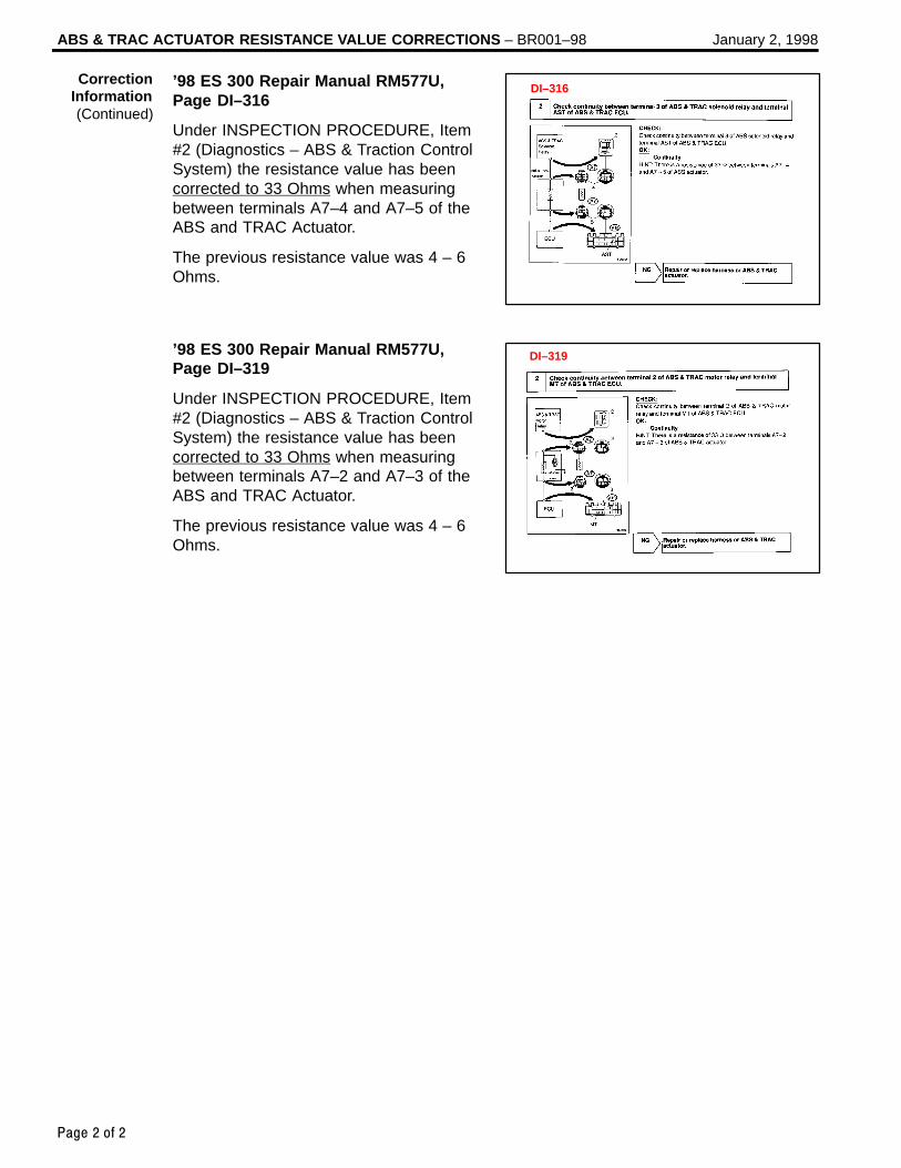
’98 ES 300 Repair Manual RM577U,Page DI–316
Under INSPECTION PROCEDURE, Item#2 (Diagnostics – ABS & Traction ControlSystem) the resistance value has beencorrected to 33 Ohms when measuringbetween terminals A7–4 and A7–5 of theABS and TRAC Actuator.
The previous resistance value was 4 – 6Ohms.
’98 ES 300 Repair Manual RM577U,Page DI–319
Under INSPECTION PROCEDURE, Item#2 (Diagnostics – ABS & Traction ControlSystem) the resistance value has beencorrected to 33 Ohms when measuringbetween terminals A7–2 and A7–3 of theABS and TRAC Actuator.
The previous resistance value was 4 – 6Ohms.
CorrectionInformation(Continued)
DI–316
DI–319

Lexus Supports ASE Certification Page 1 of 1
Title:
FRONT BRAKE NOISEModels:
’97–’99 ES 300Technical Service
Information BulletinMarch 26, 1999
BR
001–99
New Front Brake Pads are available to reduce front brake groan or grinding noise on1997–1999 ES 300.
1997 to 1999 ES 300s built before VIN:Tsutsumi: JT8BF28G * * –0179640TMK: JT8BF28G * * –5064736
PART NUMBER PART NAME
04465–33121 Front Brake Pads
04945–33040 Shim Kit (If Needed*)
* Visually inspect Shims for heat discoloration. If discolored, then replace.
1. Surface the disc rotors with the “On–Car Brake Lathe” to within serviceable limits.
2. If the rotors are unserviceable or below minimum thickness, replace the rotors.
3. Check any new disc rotors for runout.
4. If the disc rotor runout is over 0.03 mm (0.0012 in), perform phase matchingprocedure.
5. Replace the front brake pads.
6. Road test.
OP CODE COMB DESCRIPTION TIME OPN T1 T2
Grind Front Discs and Replace Pads, Shims (if needed) for Squeak (both sides)
36 99
473025 AGrind Front Discs and Replace Pads, Shims
(if needed) for Vibration (both sides) 2.1 04465–33121 21 99
Grind Front Discs and Replace Pads, Shims (if needed) for Groan/Grinding (both sides)
91 99
Applicable Warranty*:This repair is covered under the Lexus Basic Warranty. This warranty is in effect for48 months or 50,000 miles, whichever occurs first, from the vehicle’s in–service date.
* Warranty application is limited to correction of a problem based upon a customer’s specific complaint.
BR
AK
ES
Introduction
PartsInformation
RepairProcedure
WarrantyInformation

Page 1 of 4Lexus Supports ASE Certification
Title:
BRAKE PAD CLICKING NOISEModels:
’90 – ’00 All ModelsTechnical Service
Information BulletinOctober 20, 2000
BR
003–00
A clicking type noise may be noticed when first applying the brakes after changingvehicle travel direction (Drive/Forward to Reverse, Reverse to Drive/Forward). This isa normal noise caused by the required brake pad–to–caliper clearances. When thedirection of travel is changed, the brake pads may “shift” towards the new direction oftravel. When the brake pad contacts the caliper, a clicking noise may be heard.
To minimize this clicking noise, a disc brake caliper grease has been made available foruse during brake service/maintenance operations. Under normal usage conditions thisgrease should be effective for a period of 6 months to 1 year.
1990 – 2000 model year Lexus vehicles, all models.
PREVIOUS PART NUMBER CURRENT PART NUMBER PART NAME
N/A 08887–80609 Disc Brake Caliper Grease (50 g tube)
OP CODE DESCRIPTION TIME OPN T1 T2
N/A Not Applicable to Warranty – – – –
BR
AK
ES
Introduction
ApplicableVehicles
PartsInformation
WarrantyInformation

BRAKE PAD CLICKING NOISE – BR003–00 October 20, 2000
Page 2 of 4
There are two types of brake calipers: floating and fixed. Check the type of brake caliperinstalled on the vehicle by removing the wheel assembly.
1. Floating Type Brake Caliper
A. Lift up or remove the brake caliperand suspend it securely.
HINT:Do not disconnect the flexible hosefrom the brake caliper.
B. If equipped with anti–squealspring: Remove the anti–squealsprings.
C. Remove the brake pads withanti–squeal shims.
D. Remove the pad support platesfrom the torque plate. Clean anydust from the pad support plates,torque plates and brake pads.
E. Apply a small amount of the disc brake caliper grease (1–2 mm thick) to both sides of the pad support plates.
NOTE:Do NOT apply grease to the frictionsurfaces of the brake pads or thedisc rotor.
F. If the pad support plate is fixed tothe torque plate with adhesive tape,perform the operation according tothe following flow chart.
Without removing the padsupport plate, apply a smallamount of grease to the portionwhere the pad touches thesurface of the support plate.
Fixed firmly in placeThere is adhesive tape, butit is not fixed firmly in place Adhesive tape is peeled off
Remove the pad support plate,peel off the adhesive tape andapply a small amount of grease toboth sides of the support plate.
Remove the pad support plateand apply a small amount ofgrease to both sides of thesupport plate.
Check whether or not the pad support plateand the torque plate are fixed firmly in placewith adhesive tape.
ApplicationProcedure
Pad SupportPlates
TorquePlate
Apply Disc Brake Caliper Grease
Pad Support Plates

BRAKE PAD CLICKING NOISE – BR003–00 October 20, 2000
Page 3 of 4
G. Apply a small amount of the disc brake caliper grease(1–2 mm thick) to the caliper as indicated in the illustration.
H. Install the brake pads with theanti–squeal shims.
I. If equipped with anti–squealspring: Install the anti–squealsprings.
J. Press the piston in firmly andinstall the brake caliper.
NOTE: Clean excess grease from brake
pad and caliper. Do NOT apply grease to the friction
surfaces of the brake pads or thedisc rotor.
K. Install the wheel assembly.
2. Fixed Type Brake CaliperThere are two types of brake pads:
Type “A”: Has a projection on theupper and lower side of the brakepad. (See illustration.)
Type “B”: Has a flat upper andlower edge on the brake padbacking plate.
Type “A” Brake PadA. Remove the anti–squeal spring,
clip and pad guide pin.B. Remove the brake pads with the
anti–squeal shims.C. Clean any dust from the brake
pads.
ApplicationProcedure(Continued)
Apply Disc BrakeCaliper Grease
Type “A”Brake Pad
Type “B”Brake Pad
Projection
Flat Edge
Type “A” Brake Pad

BRAKE PAD CLICKING NOISE – BR003–00 October 20, 2000
Page 4 of 4
D. Apply a small amount of the disc brake caliper grease (1–2 mm thick) to the areasindicated in the illustration.
NOTE:Do NOT apply grease to the frictionsurfaces of the brake pads or thedisc rotor.
E. Install the brake pads with theanti–squeal shims.
NOTE:Clean excess grease from the brakepads and caliper.
F. Install the pad guide pin, clip andanti–squeal spring.
G. Install the wheel assembly.
Type “B” Brake PadA. Remove the clip, pins and
anti–rattle spring/pad retainer clip.B. Remove the brake pads with the
anti–squeal shims.C. Clean any dust from the brake
pads.
D. Apply a small amount of the disc brake caliper grease (1–2 mm thick) to the areasindicated in the illustration.
NOTE:Do NOT apply grease to the frictionsurfaces of the brake pads or thedisc rotor.
E. Install the brake pads with theanti–squeal shims.
NOTE:Clean excess grease from the brakepads and caliper.
F. Install the pad guide pin, clip andanti–squeal spring.
G. Install the wheel assembly.
ApplicationProcedure(Continued)
Apply Disc BrakeCaliper Grease
Type “B” Brake Pad
Apply Disc BrakeCaliper Grease

Lexus Supports ASE Certification Page 1 of 1
Title:
SULFUR ODOR FROM EXHAUSTModels:
All ModelsTechnical Service
Information BulletinFebruary 24, 2003
EG
001-03
Some owners of Lexus vehicles may experience a sulfur–like or “rotten egg” odor fromthe exhaust system. Sulfur is a natural component of crude oil from which gasoline isrefined and the amount of sulfur can be decreased through the refining process. Theamount of sulfur in fuel sold in California is regulated, however gasoline sold in otherstates can have substantially higher sulfur content. Sulfur content also variesconsiderably between gasoline brands and locations.
All Models.
A sulfur odor emitted from the vehicle’s tailpipe does not necessarily indicate that there isan issue with the engine’s running condition, but is most likely directly related to the fuel.If the vehicle is exhibiting an excessive sulfur odor, the following checks should beperformed:
If the MIL light is ON, check for DTCs and repair as necessary.
If no trouble is found after performing the above check, recommend the customer try adifferent source of fuel.
Replacement of oxygen sensors, air/fuel ratio sensors or catalytic converters will notreduce the odor and will therefore not be considered warrantable.
OP CODE DESCRIPTION TIME OFP T1 T2
N/A Not Applicable to Warranty – – – –
EN
GIN
E
Introduction
ApplicableVehicles
RepairProcedure
WarrantyInformation

Lexus Supports ASE Certification Page 1 of 1
Title:
EVAP SYSTEM DIAGNOSIS: P0441 /
P0446Models:
ES 300, SC 400, LS 400, LX 450
Technical ServiceInformation Bulletin
April 3, 1998
EG
001–98
The following procedure is recommended for repair of MIL “ON” conditions involvingconfirmed DTC P0441 and P0446.
All ES 300, SC 400, LS 400, LX 450 that display a code P0441 or P0446.
A. Diagnostics for P0441:
1. Remove Vacuum Hoses betweenEVAP VSV and CharcoalCanister and discard.
2. If there is a metal vapor pipebetween EVAP VSV andCharcoal Canister, clean inside ofvapor pipe.
3. Replace EVAP VSV andCharcoal Canister assembly withnew parts.
4. Install new vacuum hosesbetween EVAP VSV andCharcoal Canister.
B. Diagnostics for P0446:1. Inspect vacuum hoses and pipes
between EVAP (Purge) VSV andCharcoal Canister for leaks.
2. Replace Vapor Pressure VSV andCanister.
NOTE:When performing diagnostics for an occurrence of a MIL ”ON” condition, the DiagnosticTrouble Code (DTC) P0441 may be the result of debris in the Evaporative EmissionControl System. This may cause blockage of a vapor line, or a stuck VSV, as describedin the troubleshooting area of the Repair Manual.
OP CODE DESCRIPTION TIME OPN T1 T2
N/A Not Applicable to Warranty – – – –
EN
GIN
E
Introduction
AffectedVehicles
Affected Area(shaded line)
VSV forEVAP
Charcoal Canister Fuel Tank
VSV forVaporPressureSensor
Vapor PressureSensor
Charcoal Canister Assembly (broken line)
ECM
WarrantyInformation

Toyota Supports ASE Certification Page 1 of 11
Title:
EVAP SYSTEM OPERATION
INFORMATIONModels:
All ’96 – ’01 Models
Technical ServiceInformation Bulletin
April 27, 2001
EG
002-01
This service bulletin provides supplemental information regarding the system design,operation, and diagnostics of the Early Type (Non–Intrusive) and Late Type (Intrusive)EVAP Systems found on 1996 model year and later OBD II equipped vehicles.
MODEL 1996 1997 1998 1999 2000 2001
ES 300 Early Early Early Early Late Late
GS 300 N/A N/A Early Early Early Late
GS 400 N/A N/A Early Early Early N/A
GS 430 N/A N/A N/A N/A N/A Late
IS 300 N/A N/A N/A N/A N/A Late
LS 400 N/A N/A Early Early Late N/A
LS 430 N/A N/A N/A N/A N/A Late
LX 470 N/A N/A Early Early Early Early
RX 300 N/A N/A N/A Early Late Late
SC 300 N/A N/A Early Early Late N/A
SC 400 N/A Early Early Early Late N/A
This bulletin is divided into the following sections:Early Type and Late Type EVAP System Outline
1. Early Type Description Pages 2–4. . . . . . . . . . . . . . . . . . . . 2. Late Type Description Pages 4–5. . . . . . . . . . . . . . . . . . . . . 3. Late Type System Monitor Sequence Pages 6–8. . . . . .
Diagnostic Tips For Late Type EVAP System Pages 8–11. . . . . . . . . .
OP CODE DESCRIPTION TIME OPN T1 T2
N/A Not Applicable to Warranty – – – –
EN
GIN
E
Introduction
ApplicableVehicles
Contents
WarrantyInformation

EVAP SYSTEM OPERATION INFORMATION – EG002-01 April 27, 2001
Page 2 of 11
Early Type (Non–Intrusive) EVAP System Overview
There are a variety of EVAP systems in use with different monitoring strategies. It isessential that the EVAP system be correctly identified before beginning diagnosis. TheRepair Manual is the best source for this information. The following information coversthe different systems.
The first system described is the Early Type (Non–Intrusive) EVAP System. Refer to theApplicable Vehicles chart for applicability information.
Onboard Recovery Valve(Fill Check Valve) Vapor
PressureSensor
VaporPressureSensorThree WayVSV
VacuumCheckValve
Tank ValveAssembly Pressure
Valve Canister
ToManifoldVacuum
PurgeValve
FilteredAir
Air Drain ValveAir Valve Assembly
Air Inlet ValveAir Inlet LineServicePort
Purge OperationWhen the engine has reachedpredetermined parameters (closed loop,engine temp. above 125F, etc.), storedfuel vapors are purged from the canisterwhenever the purge VSV is opened bythe ECM. At the appropriate time, theECM will turn on the purge VSV.
The ECM will change the duty ratio cycleof the purge VSV thus controlling purgeflow volume. Purge flow volume isdetermined by manifold pressure and theduty ratio cycle of the purge VSV.Atmospheric pressure is allowed into thecanister to ensure that purge flow isconstantly maintained whenever purgevacuum is applied to the canister (seeFigure 1).
Early TypeSystem
Description
Figure 1. Purge Operation
Fresh Air Inlet
Purge VSV

EVAP SYSTEM OPERATION INFORMATION – EG002-01 April 27, 2001
Page 3 of 11
ORVR OperationDuring refueling, low pressure above thediaphragm in the onboard recovery valvelifts allowing fuel vapors into the charcoalcanister. At the same time, the air drainvalve opens and the charcoal absorbs thefuel vapors (see Figure 2).
Early Type (Non–Intrusive) EVAP System DTCs
EVAP Monitor Leak Operation P0440The ECM tests for leaks by measuringEVAP system pressure in the lines,charcoal canister, and fuel tank. Whenthe EVAP pressure is higher or lower thanatmospheric pressure, the ECMconcludes that no leaks are present.EVAP pressure is measured by the vaporpressure sensor. If either the tank orcanister purge side is at atmosphericpressure under specific conditions, theECM determines there is a leak.
If DTC P0440 is present, the leak is onthe fuel tank side of the EVAP system.This also includes the lines between thefuel tank and part of the canister. Whenthe Vapor Pressure sensor is measuringtank pressure, the ECM is observingchanges in pressure and comparing tankpressure to atmospheric pressure. Nodifference in pressure indicates a leak.The ECM may take 20 minutes or more tocomplete testing the fuel tank side (seeFigure 3).
Canister Leak Detection P0446When the ECM switches the vaporpressure VSV to canister side, the ECMmeasures canister pressure. A leak onthe canister side can set multiple DTCs(see Figure 4).
Early TypeSystem
Description(Continued)
Figure 2. ORVR Operation
Figure 3. Fuel Tank Side of System
Figure 4. Canister Side of System

EVAP SYSTEM OPERATION INFORMATION – EG002-01 April 27, 2001
Page 4 of 11
Vapor Purge Flow P0441The EVAP monitor is designed to detect:
Restricted vapor purge flow when thepurge VSV is open
Inappropriate vapor purge flow whenthe purge VSV is closed
Under normal purge conditions, pressurepulsations generated by the cycling of thepurge VSV are present in the canisterand detected by the Vapor Pressuresensor.
Three–Way VSV P0446The three–way VSV is connected to the Vapor Pressure sensor, canister, and fuel tank.This VSV allows the Vapor Pressure sensor to detect either canister or tank pressure.
There are two modes the ECM can use to determine if the three–way VSV ismalfunctioning. The three–way VSV is judged to be normal if there is pressure differencebetween the tank and canister when the three–way VSV is switched to look at thecharcoal canister and fuel tank side of system.
If there isn’t any pressure difference between the fuel tank and canister, the ECM looksfor the following conditions:
During purging, pressure pulsations generated by the purge VSV are not present inthe canister as detected by Vapor Pressure sensor, the three–way VSV is judged tobe defective.
If there are pressure pulsations detected by the Vapor Pressure sensor present in thefuel tank, the three–way VSV is judged to be defective.
Late Type (Intrusive) EVAP System Overview
The Late Type EVAP System, also known as the Intrusive type, was developed to meetthe very stringent, mandated standard of detecting a hole 0.020 inch (0.5 mm). Thissystem uses many of the same components as the early type EVAP system. Purge,vacuum relief, pressure relief, and ORVR operations are identical to the early type. Referto the Applicable Vehicles chart for applicability information.
The following changes were made to the Late Type EVAP System:
Vapor pressure sensor connected to the fuel tank.
Bypass VSV in the place of the three way VSV.
Canister Closed Valve (CCV) on the air inlet line.
Figure 5. Flow During Purge Operation
Early TypeSystem
Description(Continued)
Late TypeSystem
Description

EVAP SYSTEM OPERATION INFORMATION – EG002-01 April 27, 2001
Page 5 of 11
Late Type (Intrusive EVAP System)
Onboard Recovery Valve(Fill Check Valve) Vapor
PressureSensor
VacuumCheckValve
Tank ValveAssembly
TankPressureValve Canister
ToManifoldVacuum
PurgeVSV
FilteredAir
Air DrainValve Air Valve Assembly
Air Inlet ValveCanisterClosed Valve
BypassVSV Air
Inlet Line
ServicePort
Tank SideThe bypass VSV and the fill check valveassembly isolates the tank pressure sidefrom the canister side (see Figure 1).
Canister SideThe bypass VSV and the Fill Check valvealso isolate the canister side from thetank side (see Figure 2).
Late TypeSystem
Description(Continued)
Figure 1. Fuel Tank Side of System
Figure 2. Canister Side of System
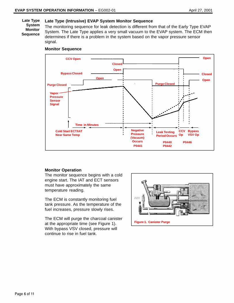
EVAP SYSTEM OPERATION INFORMATION – EG002-01 April 27, 2001
Page 6 of 11
Late Type (Intrusive) EVAP System Monitor SequenceThe monitoring sequence for leak detection is different from that of the Early Type EVAPSystem. The Late Type applies a very small vacuum to the EVAP system. The ECM thendetermines if there is a problem in the system based on the vapor pressure sensorsignal.
Monitor Sequence
P0441P0440P0442
P0446
CCV Open
Purge Closed
Open
Closed
Purge ClosedOpen
Open
Cold Start ECT/IATNear Same Temp
NegativePressure(Vacuum)Occurs
Leak TestingPeriod Occurs
CCVOp
Open
Time in Minutes
Bypass Closed Closed
BypassVSV Op
VaporPressureSensor Signal
Monitor Operation The monitor sequence begins with a coldengine start. The IAT and ECT sensorsmust have approximately the sametemperature reading.
The ECM is constantly monitoring fueltank pressure. As the temperature of thefuel increases, pressure slowly rises.
The ECM will purge the charcoal canisterat the appropriate time (see Figure 1).With bypass VSV closed, pressure willcontinue to rise in fuel tank.
Late TypeSystemMonitor
Sequence
Figure 1. Canister Purge

EVAP SYSTEM OPERATION INFORMATION – EG002-01 April 27, 2001
Page 7 of 11
Purge VSV Operation – P0441At a predetermined point, the ECM closesthe CCV and opens the Bypass VSVcausing vacuum to increase in the entireEVAP system.
The ECM continues to operate the purgeVSV until the vacuum is increased to aspecified point at which time the ECMcloses the purge VSV (see Figure 2).
If the vacuum did not increase, or if thevacuum increased beyond the specifiedlimit, the ECM judges the purge VSV andrelated components to be faulty.
Hole Detection P0440 and P0442The rate of pressure increase as detectedby the vapor pressure signal indicates theif there is a leak and if it is a large orsmall leak.
After purge valve operation, the purgeVSV is turned off sealing the vacuum inthe system and the ECM begins tomonitor the pressure increase (seeFigure 3). Some increase is normal. Avery rapid, sharp increase in pressureindicates a leak in the EVAP system andsets the DTC P0440.
This monitoring method is also able todistinguish what is called the small leakdetection. A pressure rise just abovenormal indicates a very small hole andwill set the DTC P0442.
Vent Control, CCV Operation P0446This stage checks the CCV and vent (airinlet side) operation. When the vaporpressure rises to a specified point, theECM opens the CCV. Pressure willincrease rapidly because of the airallowed into the system. No increase oran increase below specified rate ofpressure increase indicates a restrictionon the air inlet side.
Late TypeSystemMonitor
Sequence(Continued)
Figure 2. Vacuum Application
Figure 3. System Sealed
Figure 4. CCV Opens

EVAP SYSTEM OPERATION INFORMATION – EG002-01 April 27, 2001
Page 8 of 11
Bypass VSV Operation P0446In the next stage, the ECM closes thebypass VSV. This action blocks airentering the fuel tank side of the system.The pressure rise on the fuel tank side isno longer as great. If there was nochange in pressure, the ECM willconclude the bypass VSV did not close.
This diagnostic process tests the EVAP System. The following diagnostic tips may beused in conjunction with the Diagnostic Procedures for EVAP DTCs listed in the RepairManual. They may be used for all Late Type (Intrusive) EVAP Systems and for all EVAPDTCs. Refer to the Applicable Vehicles chart for applicability information.
The EVAP System Pressure Test Kit (P/N 00002–6872A) and the Scan Tool can be usedto diagnose the EVAP System. Measuring EVAP System pressures using the EVAPSystem Pressure Tester Gauge and the Scan Tool can aid in the identification of leaks inthe system.
System Outline
Onboard Recovery Valve(Fill Check Valve)
ToManifoldVacuum
FilteredAir
PurgeValve
CanisterClosedValve Bypass
Valve
Air DrainValve Air Valve
Assembly
Air InletValve
Canister
Tank Pressure ValveVaporPressureSensor Vacuum
CheckValve
Tank ValveAssembly
Late TypeSystemMonitor
Sequence(Continued)
Figure 5. Bypass VSV Closes
DiagnosticTips for Late
Type EVAPSystem

EVAP SYSTEM OPERATION INFORMATION – EG002-01 April 27, 2001
Page 9 of 11
DO NOT PROCEED!NG
OK
SCAN TOOL SETUPA) Connect Scan Tool to DLC3 on vehicle.B) Go to the SETUP menu and select UNIT CONVERSION.C) Under VAPOR PRESSURE, Select ABS for absolute pressure, and mmHg for millimeters of mercury.
This is to match the Repair Manual specifications.D) Go back to FUNCTION SELECT menu and select ENHANCED OBD II.E) Select NORMAL MODE. Then select CURRENT DATA and USER SELECT.F) Using the arrow key, select VAPOR PRESS from the DATA LIST and select YES.G) Press ENTER. You will now be able to monitor the Vapor Pressure Sensor reading.
PRELIMINARY CHECK Fuel level should be between
1/4 and 3/4 Visually inspect for pressure
Fuel CapDO NOT TIGHTEN OR REMOVE!
START
PRESSURIZE EVAP SYSTEM (System Integrity Check)This test checks for leaks in the canister and fuel tank sides. The CCV and Air Inlet Lines will be checkedseparately.A) Clamp air drain line with supplied hose pliers.B) Locate the vapor pressure sensor. If the pressure sensor has two hoses connected to it, disconnect
the hose between the air drain and pressure sensor at the pressure sensor and plug the hose.C) Pressurize EVAP system. Turn off the pump and seal system (See pump directions)D) Note pump pressure readings and Vapor Pressure Sensor reading.E) Compare the results to one of the four conditions listed below and proceed as directed.
Diagnostic Process Flow Chart
(Continued on following page)
Pump pressure gauge and vapor pressure above atmospheric pressure (above 762 mmHg). No leak in canister or tank.
Pump pressure gauge zero, vaporpressure above atmosphericpressure (above 762mmHg). Leak is on canister side of system.
Pump pressure gauge is above atmospheric pressure (above zero), vapor pressure is at 762 mmHg. Leak is on the fuel tank side of system.
Pump pressure gauge at zero, vapor pressure is at 762 mmHg. The leak(s) is/are on the canister and tank sides or a leak at a point common to both sides of system.
Remove hose pliers from the air drain hose on the charcoalcanister beforeproceeding with additional checks.
Remove hose pliers from the air drain hose on the charcoalcanister before proceeding with additional checks.
Remove hose pliers from the air drain hose on the charcoalcanister before proceeding with additional checks.
Go to CCV/Air Inlet Line Check.
Go to “Canister LeakCheck.” Diagram on page 11.
Go to “Fuel Tank Leak Check.” Diagram on page 10.
Go to “Fuel Tank Leak Check.” Diagram on page 10.
Remove hose pliers from the air drain hose on the charcoalcanister before proceeding with additional checks.
DiagnosticTips for Late
Type EVAPSystem
(Continued)

EVAP SYSTEM OPERATION INFORMATION – EG002-01 April 27, 2001
Page 10 of 11
Go to “Return Vehicle to Service” on page 11.
CCV and Air Inlet Line Check.A) Disconnect the air inlet line from the charcoal canister.B) Using the supplied step–down brass adapter (or equivalent) connect the Pressure Supply Hose to
the air inlet line.C) Using the Scan Tool Active Test, turn on the CCV. This will close the CCV.D) Pressurize the line. Once pressurized, turn off the pump and seal the line (Pressure Hold Switch to
“Closed” and Vent Switch to “Closed”). Pressure should hold. If not, check CCV and connections.E) Next, using the Scan Tool, turn off the CCV. This will open the CCV. The pressure should decrease.
If not, check the CCV and connections.F) After completing the test, reconnect air inlet line to charcoal canister.
Diagnostic Process Flow Chart (Continued)
(Continued from previous page)
DisconnectEVAP Hose Here
A. Using the supplied brass step–down adapter, disconnect the EVAP hose from the charcoal canister side as indicated above. Connect Pressure Supply hose from Pressure Test Kit to the EVAP hose and pressurize the fuel tank to 30 mmHg (4 kPa / 0.58 psi).
B. Check that the internal pressure of the tank will hold for 1 minute. Check shadedareas for leaks (soapy water can be used for leak detection). If pressure holds, thenperform the Canister Leak Check.
C. When done, reconnect the EVAP line hose to the charcoal canister.
Fuel Tank Leak Check
DiagnosticTips for Late
Type EVAPSystem
(Continued)

EVAP SYSTEM OPERATION INFORMATION – EG002-01 April 27, 2001
Page 11 of 11
Canister Leak Check
A. Connect the Pressure Supply hose from the Pressure Test Kit to the Green EVAPSystem Service Port located on the EVAP Purge VSV line in the engine compartment.
B. Using the directions on the inside of the EVAP System Pressure Test Kit lid, pressurize the EVAP system. Once pressurized, turn off the pump and seal the system(Pressure Hold Switch to “Closed” and Vent Switch to “Closed”)
C. With system pressurized at EVAP Service Port, check shaded areas for leaks (soapy water can be used for leak detection).
Return Vehicle to ServiceA. After performing above checks, be sure to reconnect all lines and verify that all
plugs and hose pliers used for diagnosis have been removed.B. For additional diagnostic procedures and information, refer to the appropriate
Repair Manual.
DiagnosticTips for Late
Type EVAPSystem
(Continued)

Lexus Supports ASE Certification Page 1 of 15
Title:
READINESS MONITOR DRIVE PATTERNSModels:
All ’96 – ’02Technical Service
Information BulletinFebruary 8, 2002
EG
002-02
The On–Board Diagnostic (OBDII) system is designed to monitor the performance ofemission–related components and report any detected abnormalities in the form ofDiagnostic Trouble Codes (DTCs). Since the various components need to be monitoredduring different driving conditions, the OBDII system is designed to run separatemonitoring programs called Readiness Monitors. Many state Inspection andMaintenance (I/M) programs require that vehicles complete their Readiness Monitorsprior to beginning an emissions test.
The current status of the Readiness Monitors can be seen by using the Lexus DiagnosticTester with version 9.0 software (or newer), or a generic OBDII Scantool. To view theReadiness Monitor status using the Lexus Diagnostic Tester, select “Monitor Status” from the Enhanced OBDII Menu. A status of “complete” indicates that the necessaryconditions have been met to run the performance tests for the related Readiness Monitor.
The Readiness Monitor will be reset to “incomplete” if: ECU has lost power (battery or fuse). DTCs have been cleared. The conditions for running the Readiness Monitor have not been met.
In the event that any Readiness Monitor shows “incomplete,” follow the appropriateReadiness Monitor Drive Pattern to change the readiness status to “complete.” Refer to the Readiness Monitor Drive Pattern Application Table to determine whichdrive pattern should be followed.
SECTION PAGE(S)
Readiness Monitor Drive Pattern Application Tables 2–3
Readiness Monitor Drive Patterns
1 EGR Monitor (All Except 1FZ–FE Engine) 4
2 EGR Monitor (For 1FZ–FE Engine) 5
3 Catalyst Monitor (O2S Type) 6
4 Catalyst Monitor (AF Sensor Type) 7
5 EVAP Monitor (Internal Pressure Monitor/Non–Intrusive Type) 8–9
6 EVAP Monitor (Vacuum Pressure Monitor/Intrusive Type) 10–11
7 EVAP Monitor (Without Leak Detection) 12
8 Oxygen Sensor Monitor (Front and Rear O2S System) 13
9 Oxygen/AF Sensor Monitor (Front AF Sensor and Rear O2S System) 14
10 Oxygen/AF Sensor Heater Monitor 15
All 1996 – 2002 model year Lexus vehicles.
OP CODE DESCRIPTION TIME OPN T1 T2
N/A Not Applicable to Warranty – – – –
EN
GIN
E
Introduction
Contents
ApplicableVehicles
WarrantyInformation
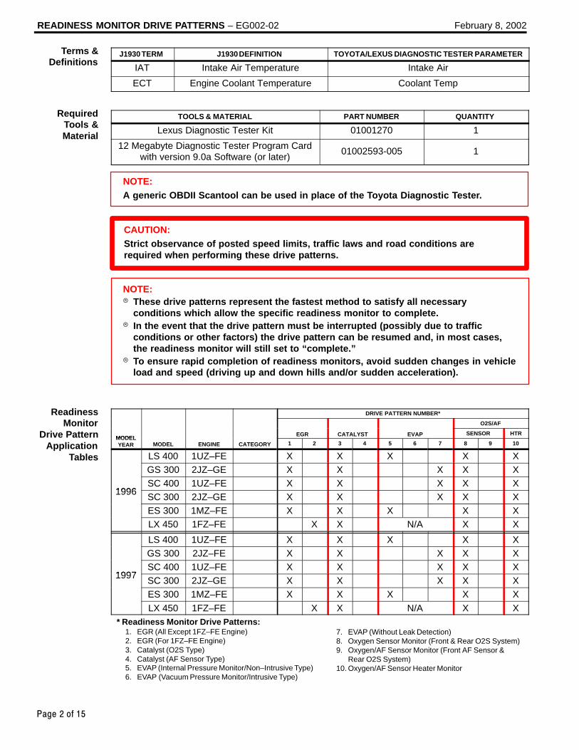
READINESS MONITOR DRIVE PATTERNS – EG002-02 February 8, 2002
Page 2 of 15
J1930 TERM J1930 DEFINITION TOYOTA/LEXUS DIAGNOSTIC TESTER PARAMETER
IAT Intake Air Temperature Intake Air
ECT Engine Coolant Temperature Coolant Temp
TOOLS & MATERIAL PART NUMBER QUANTITY
Lexus Diagnostic Tester Kit 01001270 1
12 Megabyte Diagnostic Tester Program Cardwith version 9.0a Software (or later)
01002593-005 1
NOTE:A generic OBDII Scantool can be used in place of the Toyota Diagnostic Tester.
CAUTION:Strict observance of posted speed limits, traffic laws and road conditions arerequired when performing these drive patterns.
NOTE: These drive patterns represent the fastest method to satisfy all necessary
conditions which allow the specific readiness monitor to complete. In the event that the drive pattern must be interrupted (possibly due to traffic
conditions or other factors) the drive pattern can be resumed and, in most cases,the readiness monitor will still set to “complete.”
To ensure rapid completion of readiness monitors, avoid sudden changes in vehicleload and speed (driving up and down hills and/or sudden acceleration).
DRIVE PATTERN NUMBER*
O2S/AF
MODELEGR CATALYST EVAP SENSOR HTR
MODELYEAR MODEL ENGINE CATEGORY 1 2 3 4 5 6 7 8 9 10
LS 400 1UZ–FE X X X X XGS 300 2JZ–GE X X X X X
1996SC 400 1UZ–FE X X X X X
1996 SC 300 2JZ–GE X X X X XES 300 1MZ–FE X X X X XLX 450 1FZ–FE X X N/A X X
LS 400 1UZ–FE X X X X XGS 300 2JZ–FE X X X X X
1997SC 400 1UZ–FE X X X X X
1997 SC 300 2JZ–GE X X X X XES 300 1MZ–FE X X X X X
LX 450 1FZ–FE X X N/A X X* Readiness Monitor Drive Patterns:
1. EGR (All Except 1FZ–FE Engine)2. EGR (For 1FZ–FE Engine)3. Catalyst (O2S Type)4. Catalyst (AF Sensor Type)5. EVAP (Internal Pressure Monitor/Non–Intrusive Type)6. EVAP (Vacuum Pressure Monitor/Intrusive Type)
7. EVAP (Without Leak Detection)8. Oxygen Sensor Monitor (Front & Rear O2S System)9. Oxygen/AF Sensor Monitor (Front AF Sensor & Rear O2S System)10. Oxygen/AF Sensor Heater Monitor
Terms &Definitions
RequiredTools &Material
ReadinessMonitor
Drive PatternApplication
Tables

READINESS MONITOR DRIVE PATTERNS – EG002-02 February 8, 2002
Page 3 of 15
DRIVE PATTERN NUMBER*
O2S/AF
MODELEGR CATALYST EVAP SENSOR HTR
MODELYEAR MODEL ENGINE CATEGORY 1 2 3 4 5 6 7 8 9 10
LS 400 1UZ–FE X X X XGS 300 2JZ–FE
N/AX X X X
SC 400 1UZ–FEN/A
X X X X
1998 SC 300 2JZ–GE X X X X1998
ES 300 1MZ FEFed X X X X X
ES 300 1MZ–FECA X X X X X
LX 470 2UZ–FE X X X X X
LS 400 1UZ–FE X X X XGS 400 1UZ–FE X X X XGS 300 2JZ–FE X X X X
1999SC 400 1UZ–FE
N/AX X X X
1999 SC 300 2JZ–FE N/A X X X XES 300 1MZ–FE X X X XLX 470 2UZ–FE X X X XRX 300 1MZ–FE X X X X
LS 400 1UZ–FE X X X XGS 400 1UZ–FE X X X XGS 300 2JZ–FE X X X X
2000SC 400 1UZ–FE
N/AX X X X
2000 SC 300 2JZ–FE N/A X X X XES 300 1MZ–FE X X X XLX 470 2UZ–FE X X X XRX 300 1MZ–FE X X X X
LS 430 3UZ–FE X X X XGS 430 3UZ–FE X X X XGS 300 2JZ–FE X X X X
2001 IS 300 2JZ–FE N/A X X X X2001ES 300 1MZ–FE
N/AX X X X
LX 470 2UZ–FE X X X XRX 300 1MZ–FE X X X X
LS 430 3UZ–FE X X X XGS 430 3UZ–FE X X X XGS 300 2JZ–FE X X X X
2002SC 430 3UZ–FE
N/AX X X X
2002 IS 300 2JZ–FE N/A X X X XES 300 1MZ–FE X X X XLX 470 2UZ–FE X X X XRX 300 1MZ–FE X X X X
* Readiness Monitor Drive Patterns:1. EGR (All Except 1FZ–FE Engine)2. EGR (For 1FZ–FE Engine)3. Catalyst (O2S Type)4. Catalyst (AF Sensor Type)5. EVAP (Internal Pressure Monitor/Non–Intrusive Type)6. EVAP (Vacuum Pressure Monitor/Intrusive Type)
7. EVAP (Without Leak Detection)8. Oxygen Sensor Monitor (Front & Rear O2S System)9. Oxygen/AF Sensor Monitor (Front AF Sensor & Rear O2S System)10. Oxygen/AF Sensor Heater Monitor
ReadinessMonitor
Drive PatternApplication
Tables(Continued)

READINESS MONITOR DRIVE PATTERNS – EG002-02 February 8, 2002
Page 4 of 15
DRIVE PATTERN NO. 1: EGR Monitor (All Except 1FZ–FE Engine)
Warm up10 min
43 – 56 mph(70 – 90 km/h)
Idling
IG SW off
3 – 5 min 3 – 5 min3 – 5 min(b)
3 – 5 min(c)
(d)(a)
PreconditionsThe monitor will not run unless:
MIL is OFF. Altitude is 7800 feet (2400 m) or less. IAT (Intake Air) is 14F (–10C) or greater.
Drive Pattern ProcedureConnect the OBDII Scantool to the DLC3 connector to check monitor status andpreconditions.
a. If IAT (Intake Air) is less than 50F (10C) when starting the engine, idle theengine for approximately 10 minutes.
b. Drive the vehicle at 43 – 56 mph (70 – 90 km/h) for a period of 3 – 5 minutes.
NOTE: Do not allow the Throttle Position (TP) to exceed 30%. Drive with smooth throttle operation and avoid sudden acceleration.
c. Stop the vehicle and let the engine idle for 3 – 5 minutes.d. Repeat steps “b” and “c” once.
If readiness status does not switch to “complete,” ensure preconditions are met, turn theignition OFF, then repeat steps “b” through “d.”
NOTE:The readiness status may not switch to “complete” after the first drive pattern trip if aPending Code has been set (first trip for a two–trip DTC). Pending Codes are available from the DTC Info Menu in Enhanced OBDII. Pending Codes indicate a POTENTIAL problem was detected. A second trip is
needed to confirm the DTC prior to diagnosis. Once a second trip is completed, a current DTC will be stored.
ReadinessMonitor
DrivePatterns:
EGR Monitors

READINESS MONITOR DRIVE PATTERNS – EG002-02 February 8, 2002
Page 5 of 15
DRIVE PATTERN NO. 2: EGR Monitor (for 1FZ–FE Engine)
43 – 56 mph(70 – 90 km/h)
IdlingIG SW off
3 – 5 min 3 – 5 min3 – 5 min(b)
3 – 5 min
(c)(a)
Preconditions
The monitor will not run unless:
MIL is OFF.
Altitude is 7800 feet (2400 m) or less.
IAT (Intake Air) is 14F (–10C) or greater.
ECT (Coolant Temp) is less than 104F (40C).
Drive Pattern Procedure
Connect the OBDII Scantool to DLC3 to check monitor status and preconditions.
a. Start the engine and as soon as safely possible begin driving the vehicle at 43 –56 mph (70 – 90 km/h) for a period of 3 – 5 minutes.
NOTE: Do not allow the Throttle Position (TP) to exceed 30%. Drive with smooth throttle operation and avoid sudden acceleration.
b. Stop the vehicle and let the engine idle for 3 – 5 minutes.
c. Repeat steps “a” and “b” once.
If readiness status does not switch to “complete,” ensure preconditions are met, turn theignition OFF, then repeat steps “a” through “c.”
NOTE:The readiness status may not switch to “complete” after the first drive pattern trip if aPending Code has been set (first trip for a two–trip DTC). Pending Codes are available from the DTC Info Menu in Enhanced OBDII. Pending Codes indicate a POTENTIAL problem was detected. A second trip is
needed to confirm the DTC prior to diagnosis. Once a second trip is completed, a current DTC will be stored.
ReadinessMonitor
DrivePatterns:
EGR Monitors(Continued)

READINESS MONITOR DRIVE PATTERNS – EG002-02 February 8, 2002
Page 6 of 15
DRIVE PATTERN NO. 3: Catalyst Monitor (O2S Type)
40 – 50 mph(64 – 88 km/h)
35 – 45 mph(56 – 72 km/h)
Idling
IG SW off
Warm upECT≥176F
IAT < 50F = 7 minIAT > 50F = 3 min
(a)
7 min(b)
PreconditionsThe monitor will not run unless: MIL is OFF. ECT (Coolant Temp) is 176F (80C) or greater. IAT (Intake Air) is 14F (–10C) or greater.*
* For 2002 MY and later vehicles: The readiness test can be completed in cold ambient conditions (less than 14F / –10C), if the drive pattern is repeated a second time after cycling the ignition OFF.
Drive Pattern ProcedureConnect the OBDII Scantool to DLC3 to check monitor status and preconditions.Note the IAT (Intake Air) value during engine startup. The driving time must be adjustedduring step “a” based upon IAT (Intake Air) value at startup.
a. Drive the vehicle at 40 – 55 mph (64 – 88 km/h) for the time described below: If IAT (Intake Air) was less than 50F (10C) when the engine was started,
drive for 7 minutes. If IAT (Intake Air) was greater than 50F (10C) when the engine was started,
drive for 3 minutes.b. Drive the vehicle at 35 – 45 mph (56 – 72 km/h) for approximately 7 minutes.
NOTE: Drive with smooth throttle operation. Avoid sudden acceleration. Avoid sudden deceleration as much as possible with the throttle fully closed.
If readiness status does not switch to “complete,” ensure preconditions are met, turn theignition OFF, then repeat steps “a” and “b.”
NOTE:The readiness status may not switch to “complete” after the first drive pattern trip if aPending Code has been set (first trip for a two–trip DTC). Pending Codes are available from the DTC Info Menu in Enhanced OBDII. Pending Codes indicate a POTENTIAL problem was detected. A second trip is
needed to confirm the DTC prior to diagnosis. Once a second trip is completed, a current DTC will be stored.
ReadinessMonitor
DrivePatterns:Catalyst
Monitors

READINESS MONITOR DRIVE PATTERNS – EG002-02 February 8, 2002
Page 7 of 15
DRIVE PATTERN NO. 4: Catalyst Monitor (AF Sensor Type)
IAT<50F=7minIAT>50F=3min
(a)
40 – 50 mph(64 – 88 km/h)
Idling
IG SW off
16 min(b)
35 – 45 mph(56 – 72 km/h)
Warm upECT≥176F
PreconditionsThe monitor will not run unless: MIL is OFF. ECT (Coolant Temp) is 176F (80C) or greater. IAT (Intake Air) is 14F (–10C) or greater.*
* For 2002 MY and later vehicles: The readiness test can be completed in cold ambient conditions (less than 14F / –10C), if the drive pattern is repeated a second time after cycling the ignition OFF.
Drive Pattern ProcedureConnect the OBDII Scantool to DLC3 to check monitor status and preconditions.Note the IAT (Intake Air) value during engine startup. The driving time must be adjustedduring step “a” based upon IAT (Intake Air) value at startup.
a. Drive the vehicle at 40 – 55 mph (64 – 88 km/h) for the time described below: If IAT (Intake Air) was less than 50F (10C) when the engine was started,
drive for 7 minutes. If IAT (Intake Air) was greater than 50F (10C) when the engine was started,
drive for 3 minutes.b. Drive the vehicle allowing speed to fluctuate between 35 – 45 mph (56 – 72 km/h)
for about 16 minutes.
NOTE: Drive with smooth throttle operation. Avoid sudden acceleration. Avoid sudden deceleration as much as possible with the throttle fully closed.
If readiness status does not switch to “complete,” ensure preconditions are met, turn theignition OFF, then repeat steps “a” and “b.”
NOTE:The readiness status may not switch to “complete” after the first drive pattern trip if aPending Code has been set (first trip for a two–trip DTC). Pending Codes are available from the DTC Info Menu in Enhanced OBDII. Pending Codes indicate a POTENTIAL problem was detected. A second trip is
needed to confirm the DTC prior to diagnosis. Once a second trip is completed, a current DTC will be stored.
ReadinessMonitor
DrivePatterns:Catalyst
Monitors(Continued)

READINESS MONITOR DRIVE PATTERNS – EG002-02 February 8, 2002
Page 8 of 15
DRIVE PATTERN NO. 5: EVAP Monitor (Internal Pressure Monitor/Non–Intrusive Type)
45 mph(72 km/h)
25 mph(40 km/h)
IdlingIG SW off
Soak(1b)
5 min(2a)
15 min(2b)
Warm upECT≥176F
(1a)
Cold Soak Drive Pattern
Cold Soak PreconditionsThe monitor will not run unless: MIL is OFF. Fuel level is between 1/2 to 3/4 full. Altitude is 7800 feet (2400 m) or less.
IMPORTANT:A cold soak must be performed prior to conducting the drive pattern to complete theInternal Pressure Readiness Monitor.
Cold Soak Procedure1a. Start the engine and allow ECT (Coolant Temp) to reach 176F (80C) or greater.
(This can be done by letting the engine idle or by driving the vehicle.)1b. Let the vehicle cold soak for 8 hours or until the difference between IAT (Intake
Air) and ECT (Coolant Temp) is less than 13F (7C).
Example 1 ECT (Coolant Temp) = 75F (24C). IAT (Intake Air) = 60F (16C). Difference between ECT (Coolant Temp) and IAT (Intake Air) is 15F (8C).
⇒ The monitor will not run because the difference between ECT (CoolantTemp) and IAT (Intake Air) is greater than 13F (7C).
Example 2 ECT (Coolant Temp) = 70F (21C). IAT (Intake Air) = 68F (20C). Difference between ECT (Coolant Temp) and IAT (Intake Air) is 2F (1C).
⇒ The monitor will run because the difference between ECT (Coolant Temp)and IAT (Intake Air) is less than 13F (7C).
ReadinessMonitor
DrivePatterns:
EVAPMonitors

READINESS MONITOR DRIVE PATTERNS – EG002-02 February 8, 2002
Page 9 of 15
Drive Pattern Preconditions
The monitor will not run unless:
MIL is OFF.
Fuel level is between 1/2 to 3/4 full.
Altitude is 7800 feet (2400 m) or less.
ECT (Coolant Temp) is between 40F and 95F (4.4C – 35C).
IAT (Intake Air) is between 40F and 95F (4.4C – 35C).
Cold Soak Procedure has been completed.
NOTE:Before starting the engine, the difference between ECT (Coolant Temp) and IAT (IntakeAir) must be less than 13 F (7C). (Refer to Examples 1 and 2 on previous page.)
Drive Pattern Procedure
Connect the OBDII Scantool to DLC3 to check monitor status and preconditions.
Release the pressure in the fuel tank by removing and then reinstalling the fuel tankcap.
Start the engine and begin driving as directed.
NOTE: Do not turn the ignition off until the drive pattern is complete. Drive on smooth roads to reduce excessive fuel sloshing.
2a. Start the engine and as soon as safely possible begin driving at approximately 45mph (72km/h) for 5 minutes. (See illustration on previous page.)
2b. Drive the vehicle at approximately 25 mph (40 km/h) for 15 minutes and include aminimum of two stops for approximately 30 seconds. (See illustration on previouspage.)
The monitor should complete within approximately 20 minutes. If it does not, ensurepreconditions are met and repeat the drive pattern process beginning with the Cold SoakProcedure.
NOTE:The readiness status may not switch to “complete” after the first drive pattern trip if aPending Code has been set (first trip for a two–trip DTC). Pending Codes are available from the DTC Info Menu in Enhanced OBDII. Pending Codes indicate a POTENTIAL problem was detected. A second trip is
needed to confirm the DTC prior to diagnosis. Once a second trip is completed, a current DTC will be stored.
ReadinessMonitor
DrivePatterns:
EVAPMonitors
(Continued)

READINESS MONITOR DRIVE PATTERNS – EG002-02 February 8, 2002
Page 10 of 15
DRIVE PATTERN NO. 6: EVAP Monitor (Vacuum Pressure Monitor/Intrusive Type)
IdlingIG SW off
Warm up(2a)
Soak(1a)
15 –50 min(When the Readiness Monitor orDTC is set, this test is complete.)
(2c)10 sec(2b)
3,000 rpm
Cold Soak Preconditions
The monitor will not run unless:
MIL is OFF.
Fuel level is between 1/2 to 3/4 full.
Altitude is 7800 feet (2400 m) or less.
Cold Soak Procedure
1a. Let the vehicle cold soak for 8 hours or until the difference between IAT (IntakeAir) and ECT (Coolant Temp) is less than 13F (7C).
Example 1
ECT (Coolant Temp) = 75F (24C).
IAT (Intake Air) = 60F (16C).
Difference between ECT (Coolant Temp) and IAT (Intake Air) is 15F (8C).
⇒ The monitor will not run because the difference between ECT (CoolantTemp) and IAT (Intake Air) is greater than 13F (7C).
Example 2
ECT (Coolant Temp) = 70F (21C).
IAT (Intake Air) = 68F (20C).
Difference between ECT (Coolant Temp) and IAT (Intake Air) is 2F (1C).
⇒ The monitor will run because the difference between ECT (Coolant Temp)and IAT (Intake Air) is less than 13F (7C).
ReadinessMonitor
DrivePatterns:
EVAPMonitors
(Continued)

READINESS MONITOR DRIVE PATTERNS – EG002-02 February 8, 2002
Page 11 of 15
Drive Pattern Preconditions
The monitor will not run unless:
MIL is OFF.
Fuel level is between 1/2 to 3/4 full.
Altitude is 7800 feet (2400 m) or less.*
ECT (Coolant Temp) is between 40F and 95F (4.4C – 35C).
IAT (Intake Air) is between 40F and 95F (4.4C – 35C).*
Cold Soak Procedure has been completed.
* For 2002 MY and later vehicles: The readiness test can be completed in cold ambient conditions (less than 40F / 4.4C) and/or at high altitudes (more than 7800 feet / 2400 m) if the complete drivepattern (including Cold Soak) is repeated a second time after cycling the ignition OFF.
NOTE:Before starting the engine, the difference between ECT (Coolant Temp) and IAT (IntakeAir) must be less than 13 F (7C). (Refer to Examples 1 and 2 on previous page.)
Drive Pattern Procedure
Connect the OBDII Scantool to DLC3 to check monitor status and preconditions.
Release the pressure in the fuel tank by removing and then reinstalling the fuel tankcap.
2a. Start the engine and allow it to idle until ECT (Coolant Temp) is 167F (75C) orgreater. (See illustration on previous page.)
2b. Race the engine at 3,000 rpm for approximately 10 seconds. (See illustration onprevious page.)
2c. Allow the engine to idle with the A/C ON (to create a slight load) for 15 – 50minutes. (See illustration on previous page.)
NOTE:If the vehicle is not equipped with A/C put a slight load on the engine by doing thefollowing: Securely set the parking brake. Block the drive wheels with wheel chocks. Allow the vehicle to idle in drive for 15 – 50 minutes.
NOTE:The readiness status may not switch to “complete” after the first drive pattern trip if aPending Code has been set (first trip for a two–trip DTC). Pending Codes are available from the DTC Info Menu in Enhanced OBDII. Pending Codes indicate a POTENTIAL problem was detected. A second trip is
needed to confirm the DTC prior to diagnosis. Once a second trip is completed, a current DTC will be stored.
ReadinessMonitor
DrivePatterns:
EVAPMonitors
(Continued)

READINESS MONITOR DRIVE PATTERNS – EG002-02 February 8, 2002
Page 12 of 15
DRIVE PATTERN NO. 7: EVAP Monitor (Without Leak Detection)
43 – 56 mph(70 – 90 km/h)
IdlingIG SW off
3 – 5 min 3 – 5 min3 – 5 min(a) (b)
3 – 5 min
(c)
Warm upECT≥181F
Preconditions
The monitor will not run unless:
MIL is OFF.
Altitude is 7800 feet (2400 m) or less.
ECT (Coolant Temp) is 181F (83C) or greater.
IAT (Intake Air) is 41F (5C) or greater.
Drive Pattern Procedure
Connect the OBDII Scantool to DLC3 to check monitor status and preconditions.
a. Drive the vehicle at 43 – 56 mph (70 – 90 km/h) for a period of 3 – 5 minutes.
NOTE: Do not allow the Throttle Position (TP) to exceed 30%. Drive with smooth throttle operation and avoid sudden acceleration.
b. Stop the vehicle and let the engine idle for 3 – 5 minutes.
c. Repeat steps “a” and “b” once.
If readiness status does not switch to “complete,” ensure preconditions are met, turn theignition OFF, then repeat steps “a” through “c.”
NOTE:The readiness status may not switch to “complete” after the first drive pattern trip if aPending Code has been set (first trip for a two–trip DTC). Pending Codes are available from the DTC Info Menu in Enhanced OBDII. Pending Codes indicate a POTENTIAL problem was detected. A second trip is
needed to confirm the DTC prior to diagnosis. Once a second trip is completed, a current DTC will be stored.
ReadinessMonitor
DrivePatterns:
EVAPMonitors
(Continued)

READINESS MONITOR DRIVE PATTERNS – EG002-02 February 8, 2002
Page 13 of 15
DRIVE PATTERN NO. 8: Oxygen Sensor Monitor (Front and Rear O2S System)
Once Twice 3 times 10 times
25 mph(40 km/h)(over 900
rpm)
Idling
IG SW off
Over2 min
(a)
Over50 sec
Over50 sec
(b)
50 sec 50 secOver40sec(c)
Over40sec
40sec
(d)
Preconditions
The monitor will not run unless:
MIL is OFF.
Drive Pattern Procedure
Connect the OBDII Scantool to DLC3 to check monitor status and preconditions.
a. Start the engine and allow it to idle for 2 minutes or more.
b. Drive the vehicle at 25 mph (40 km/h) or more for at least 50 seconds. Be sure engine speed remains above 900 rpm.
c. Stop the vehicle and allow the engine to idle for 40 seconds or more.
d. Perform steps “b” and “c” ten times.
If readiness status does not switch to “complete,” ensure preconditions are met, turn theignition OFF, then repeat steps “a” through “d.”
NOTE:The readiness status may not switch to “complete” after the first drive pattern trip if aPending Code has been set (first trip for a two–trip DTC). Pending Codes are available from the DTC Info Menu in Enhanced OBDII. Pending Codes indicate a POTENTIAL problem was detected. A second trip is
needed to confirm the DTC prior to diagnosis. Once a second trip is completed, a current DTC will be stored.
ReadinessMonitor
DrivePatterns:
OxygenMonitors

READINESS MONITOR DRIVE PATTERNS – EG002-02 February 8, 2002
Page 14 of 15
DRIVE PATTERN NO. 9: Oxygen/Air Fuel Ratio Sensor Monitor (Front AF Sensor and Rear O2S System)
40 – 70 mph(64 – 112 km/h)
(900 – 3,200 rpm)
Idling
IG SW off
Once Twice 10 times
Over2 min
(a)
Over40 sec
(d)
25 mph(40 km/h)
(over 900 rpm)
Over3 min
(b)Over
10 sec(c)
Over10 sec
(e)
Over40 sec
Over10 sec
40 sec
(f)
Preconditions
The monitor will not run unless:
MIL is OFF.
Drive Pattern Procedure
Connect the OBDII Scantool to DLC3 to check monitor status and preconditions.
a. Start the engine and allow it to idle for 2 minutes or more.
b. Drive the vehicle at 40 – 70 mph (64 – 112 km/h) or more for at least 3 minutes. Be sure to maintain engine speed between 900 and 3,200 rpm.
c. Stop the vehicle and allow the engine to idle for 10 seconds or more.
d. Drive the vehicle at 25 mph (40 km/h) for at least 40 seconds or more. Be sure to maintain engine speed above 900 rpm.
e. Stop the vehicle and allow the engine to idle for 10 seconds or more.
f. Perform steps “d” and “e” ten times.
If readiness status does not switch to “complete,” ensure preconditions are met, turn theignition switch OFF, then repeat steps “a” through “f.”
NOTE:The readiness status may not switch to “complete” after the first drive pattern trip if aPending Code has been set (first trip for a two–trip DTC). Pending Codes are available from the DTC Info Menu in Enhanced OBDII. Pending Codes indicate a POTENTIAL problem was detected. A second trip is
needed to confirm the DTC prior to diagnosis. Once a second trip is completed, a current DTC will be stored.
ReadinessMonitor
DrivePatterns:
OxygenMonitors
(Continued)

READINESS MONITOR DRIVE PATTERNS – EG002-02 February 8, 2002
Page 15 of 15
DRIVE PATTERN NO. 10: Oxygen/AF Sensor Heater Monitor
IdlingIG SW off
2 min(b)
9 min(a)
25 mph(40 km/h)
Preconditions
The monitor will not run unless:
MIL is OFF.
Drive Pattern Procedure
Connect the OBDII Scantool to DLC3 to check monitor status and preconditions.
a. Start the engine and allow it to idle for 9 minutes.
b. Drive the vehicle at 25 mph (40 km/h) or more for at least 2 minutes.
If readiness status does not switch to “complete,” ensure preconditions are met, turn theignition OFF, then repeat steps “a” and “b.”
NOTE:The readiness status may not switch to “complete” after the first drive pattern trip if aPending Code has been set (first trip for a two–trip DTC). Pending Codes are available from the DTC Info Menu in Enhanced OBDII. Pending Codes indicate a POTENTIAL problem was detected. A second trip is
needed to confirm the DTC prior to diagnosis. Once a second trip is completed, a current DTC will be stored.
ReadinessMonitor
DrivePatterns:
OxygenMonitors
(Continued)

Lexus Supports ASE Certification Page 1 of 1
Title:
CHARCOAL CANISTER
INTERCHANGEABILITYModels:
’95 – ’98 ES 300
Technical ServiceInformation Bulletin
May 29, 1998
EG
002–98
Charcoal Canister Assembly supply parts have been changed to simplify parts productionand permit interchangeability with current model vehicles.
1995 – 1998 model year ES 300.
The following table contains the part number replacement data for the involved models:
OLD PART NUMBER NEW PART NUMBER APPLICATION
77740–07011 77740–07012 9508–9604 prod. 96MY ES300
77740–33071 77740–33072 9604–9608 prod. 96MY ES300
77740–33061 77740–33062 9608– prod. 97–98 MY ES300
NOTE:New part numbers are fully interchangeable with previous part numbers.
OP CODE DESCRIPTION TIME OPN T1 T2
N/A Not Applicable to Warranty – – – –
EN
GIN
E
Introduction
AffectedVehicles
PartsInformation
WarrantyInformation

Lexus Supports ASE Certification Page 1 of 7
Title:
RADIATOR CAP INSPECTIONModels:
All ModelsTechnical Service
Information BulletinMarch 28, 2005
EG
007-05
The procedure for inspecting the radiator cap has been revised. Please refer to thefollowing procedures when inspecting the radiator cap on all Lexus models.
All Lexus models.
MANUFACTURER EQUIPMENT QTY
Snap–On/SunSVTS262A
(or equivalent)
Cooling System Tester(Radiator Cap Tester)
1
NOTE:Additional Lexus Approved Dealer Equipment may be ordered by calling LexusApproved Dealer Equipment at 1–800–368–6787.
OP CODE DESCRIPTION TIME OFP T1 T2
N/A Not Applicable to Warranty – – – –
EN
GIN
E
Introduction
ApplicableVehicles
RequiredEquipment
WarrantyInformation

RADIATOR CAP INSPECTION – EG007-05 March 28, 2005
Page 2 of 7
ITEMNO.
SPECIAL SERVICE TOOLS (SSTs) PART NUMBER QTY DRW**
1 Radiator Cap Test Set* 09230–00030–02 1 7
2 Radiator Cap Test Set (Small)* 09230–00020–02 1 7
* Essential SSTs.** Refers to drawer number in SST Storage System.
NOTE:Additional SSTs may be ordered by calling SPX/OTC at 1-800-933-8335.
1. Use the illustration below to identify the vehicle’s radiator cap type and kPa rating.
2. Proceed to the required inspection procedure for the radiator cap and kPa rating.
kPa Rating
Radiator Cap Identification
Compact CapN–Cap Plastic Cap
RequiredSSTs
Radiator CapIdentification
Procedure

RADIATOR CAP INSPECTION – EG007-05 March 28, 2005
Page 3 of 7
Type: N–cap, 88 kPa
1. Remove coolant and any foreignmaterial on rubber points “A,” “B,”and “C.”
2. Check that points “A,” “B,” and “C” are not deformed, cracked, or swollen.
3. Check that points “C” and “D” are notstuck together.
4. Apply engine coolant to points “B” and “C” before using the radiator cap tester.
Radiator Cap Tester:Snap–On/Sun P/N SVTS262A(or equivalent)
5. Before installing the radiator captester, use the applicable radiator capadaptor provided in the following SSTkits in conjunction with the radiatorcap tester:
SST P/N 09230–00030–02(09231–10080–01) or09230–00020–02 (09231–10060–01)
6. When using the radiator cap tester, tilt it more than 30 degrees.
7. Pump the radiator cap tester several times, and check themaximum pressure.
Pumping speed: 1 pump/second
HINT:Stop pumping when the valve opensand read the gauge. The gauge mustbe within the standard values listedbelow when the pressure valve opens.The cap is considered OK when thepressure holds steady or falls veryslowly, but holds within the standardvalues listed below for one minute.
Specification:
VALVE OPENING PRESSURE SPECIFIED CONDITION
Standard value (for brand–new cap)
74.0 to 103.0 kPa(0.75 to 1.05 kgf/cm2, 10.7 to 14.9 psi)
Minimum standard value (for in–service cap)
59 kPa (0.60 kgf/cm2, 8.53 psi)
If the maximum pressure is less than the minimum standard value, replace the radiatorcap sub–assembly.
Radiator CapInspectionProcedure
A
C
B D
N–Cap: 88 kPa
Radiator CapTester
RadiatorCap
30° or more

RADIATOR CAP INSPECTION – EG007-05 March 28, 2005
Page 4 of 7
Type: N–cap, 108 kPa
1. Remove coolant and any foreignmaterial on rubber points “A,” “B,”and “C.”
2. Check that points “A,” “B,” and “C” are not deformed, cracked, or swollen.
3. Check that points “C” and “D” are notstuck together.
4. Apply engine coolant to points “B” and “C” before using the radiator cap tester.
Radiator Cap Tester:Snap–On/Sun P/N SVTS262A(or equivalent)
5. Before installing the radiator captester, use the applicable radiator capadaptor provided in the following SSTkits in conjunction with the radiatorcap tester:
SST P/N 09230–00030–02(09231–10080–01) or09230–00020–02 (09231–10060–01)
6. When using the radiator cap tester, tilt it more than 30 degrees.
7. Pump the radiator cap tester several times, and check the maximum pressure.
Pumping speed: 1 pump/second
HINT:Stop pumping when the valve opensand read the gauge. The gauge mustbe within the standard values listedbelow when the pressure valve opens.The cap is considered OK when thepressure holds steady or falls veryslowly, but holds within the standardvalues listed below for one minute.
Specification:
VALVE OPENING PRESSURE SPECIFIED CONDITION
Standard value (for brand–new cap)
93.3 to 122.7 kPa(0.95 to 1.25 kgf/cm2, 13.5 to 17.8 psi)
Minimum standard value (for in–service cap)
78.5 kPa (0.80 kgf/cm2, 11.38 psi)
If the maximum pressure is less than the minimum standard value, replace the radiatorcap sub–assembly.
Radiator CapInspectionProcedure(Continued)
A
C
B D
N–Cap: 108 kPa
Radiator CapTester
30° or more
RadiatorCap

RADIATOR CAP INSPECTION – EG007-05 March 28, 2005
Page 5 of 7
Type: Compact Cap, 88 kPa
1. Remove coolant and any foreignmaterial on rubber points “A,” “B,”and “C.”
2. Check that points “A” and “B” are not deformed, cracked, or swollen.
3. Check that points “B” and “C” are notstuck together.
4. Apply engine coolant to point “B”before using the radiator cap tester.
Radiator Cap Tester:Snap–On/Sun P/N SVTS262A(or equivalent)
5. Before installing the radiator captester, use the applicable radiator capadaptor provided in the following SSTkits in conjunction with the radiatorcap tester:
SST P/N 09230–00030–02(09231–10080–01) or09230–00020–02 (09231–10060–01)
6. When using the radiator cap tester, tilt it more than 30 degrees.
7. Pump the radiator cap tester several times, and check themaximum pressure.Pumping speed: 1 pump/second
HINT:Stop pumping when the valve opensand read the gauge. The gauge mustbe within the standard values listedbelow when the pressure valve opens.The cap is considered OK when thepressure holds steady or falls veryslowly, but holds within the standardvalues listed below for one minute.
Specification:
VALVE OPENING PRESSURE SPECIFIED CONDITION
Standard value (for brand–new cap)
74.0 to 103.0 kPa(0.75 to 1.05 kgf/cm2, 10.7 to 14.9 psi)
Minimum standard value (for in–service cap)
59 kPa (0.60 kgf/cm2, 8.53 psi)
If the maximum pressure is less than the minimum standard value, replace the radiatorcap sub–assembly.
Radiator CapInspectionProcedure(Continued)
A
CB
Compact Cap: 88 kPa
Radiator CapTester
30° or more
RadiatorCap

RADIATOR CAP INSPECTION – EG007-05 March 28, 2005
Page 6 of 7
Type: Compact Cap, 108 kPa
1. Remove coolant and any foreignmaterial on rubber points “A,” “B,”and “C.”
2. Check that points “A” and “B” are not deformed, cracked, or swollen.
3. Check that points “B” and “C” are notstuck together.
4. Apply engine coolant to point “B”before using the radiator cap tester.
Radiator Cap Tester:Snap–On/Sun P/N SVTS262A(or equivalent)
5. Before installing the radiator captester, use the applicable radiator capadaptor provided in the following SSTkits in conjunction with the radiatorcap tester:
SST P/N 09230–00030–02(09231–10080–01) or09230–00020–02 (09231–10060–01)
6. When using the radiator cap tester, tilt it more than 30 degrees.
7. Pump the radiator cap tester several times, and check themaximum pressure.Pumping speed: 1 pump/second
HINT:Stop pumping when the valve opensand read the gauge. The gauge mustbe within the standard values listedbelow when the pressure valve opens.The cap is considered OK when thepressure holds steady or falls veryslowly, but holds within the standardvalues listed below for one minute.
Specification:
VALVE OPENING PRESSURE SPECIFIED CONDITION
Standard value (for brand–new cap)
93.3 to 122.7 kPa(0.95 to 1.25 kgf/cm2, 13.5 to 17.8 psi)
Minimum standard value (for in–service cap)
78.5 kPa (0.80 kgf/cm2, 11.38 psi)
If the maximum pressure is less than the minimum standard value, replace the radiatorcap sub–assembly.
Radiator CapInspectionProcedure(Continued)
A
CB
Compact Cap: 108 kPa
Radiator CapTester
30° or more
RadiatorCap

RADIATOR CAP INSPECTION – EG007-05 March 28, 2005
Page 7 of 7
Type: Plastic Cap, 108 kPa
1. Remove coolant and any foreignmaterial on O–ring “A.”
2. Check that O–ring “A” is notdeformed, cracked, or swollen.
3. Apply engine coolant to O–ring “A”and rubber point “B” before using theradiator cap tester.
Radiator Cap Tester:Snap–On/Sun P/N SVTS262A(or equivalent)
4. Before installing the radiator captester, use the applicable radiator capadaptor provided in the following SSTkits in conjunction with the radiatorcap tester:
SST P/N 09230–00030–02(09231–10080–01) or09230–00020–02 (09231–10060–01)
5. When using the radiator cap tester, tilt it more than 30 degrees.
6. Pump the radiator cap tester several times, and check themaximum pressure.
Pumping speed: 1 pump/second
HINT:Stop pumping when the valve opensand read the gauge. The gauge mustbe within the standard values listedbelow when the pressure valve opens.The cap is considered OK when thepressure holds steady or falls veryslowly, but holds within the standardvalues listed below for one minute.
Specification:
VALVE OPENING PRESSURE SPECIFIED CONDITION
Standard value (for brand–new cap)
93.3 to 122.7 kPa(0.95 to 1.25 kgf/cm2, 13.5 to 17.8 psi)
Minimum standard value (for in–service cap)
78.5 kPa (0.80 kgf/cm2, 11.38 psi)
If the maximum pressure is less than the minimum standard value, replace the radiatorcap sub–assembly.
Radiator CapInspectionProcedure(Continued)
A
B
Plastic Cap: 108 kPa
Radiator CapTester
30° or more
RadiatorCap

Lexus Supports ASE Certification Page 1 of 3
Title:
ENGINE BANK 1 AND BANK 2 A/F AND
O2 IDENTIFICATIONModels:
Applicable Models
Technical ServiceInformation Bulletin
September 3, 2004
EG
010-04
This service bulletin provides information on the proper identification of engine bank 1and engine bank 2 for correct A/F sensor and oxygen sensor replacement.
This bulletin contains information that identifies engine bank 1 and engine bank 2 on thefollowing engines: 1MZ–FE, 3MZ–FE, 1UZ–FE, 2UZ–FE and 3UZ–FE.
Bank 1 (B1) refers to the bank that includes cylinder No. 1.
Bank 2 (B2) refers to the bank opposite bank 1.
Sensor 1 (S1) refers to the sensor that is located before the catalytic converters.
Sensor 2 (S2) refers to the sensor that is located after the catalytic converters.
1994 – 2003 model year ES 300 vehicles equipped with 1MZ–FE engine .
2004 model year ES 330 and RX 330 vehicles equipped with 3MZ–FE engine .
1998 – 2000 model year GS 400 vehicles equipped with 1UZ–FE engine .
2003 – 2004 model year GX 470 vehicles equipped with 2UZ–FE engine .
1990 – 2000 model year LS 400 vehicles equipped with 1UZ–FE engine .
2001 – 2004 model year LS 430 and GS 430 vehicles equipped with 3UZ–FE engine .
1998 – 2004 model year LX 470 vehicles equipped with 2UZ–FE engine .
1999 – 2003 model year RX 300 vehicles equipped with 1MZ–FE engine .
1992 – 2000 model year SC 400 vehicles equipped with 1UZ–FE engine .
2002 – 2004 model year SC 430 vehicles equipped with 3UZ–FE engine .
OP CODE DESCRIPTION TIME OFP T1 T2
N/A Not Applicable to Warranty – – – –
EN
GIN
E
Introduction
ApplicableVehicles
WarrantyInformation

ENGINE BANK 1 AND BANK 2 A/F AND O2 IDENTIFICATION – EG010-04 September 3, 2004
Page 2 of 3
Bank 2 Bank 1
No. 8Cylinder
No. 6Cylinder
No. 4Cylinder
No. 2Cylinder
No. 7Cylinder
No. 5Cylinder
No. 3Cylinder
No. 1Cylinder
Front of Vehicle
1UZ–FE, 2UZ–FE and 3UZ–FE Engine Bank Identification
Front of VehicleBank 2
Bank 1
1MZ–FE and 3MZ–FE Engine Bank Identification
No. 6Cylinder
No. 4Cylinder
No. 2Cylinder
No. 5Cylinder
No. 3Cylinder
No. 1Cylinder
Engine BankIdentification

ENGINE BANK 1 AND BANK 2 A/F AND O2 IDENTIFICATION – EG010-04 September 3, 2004
Page 3 of 3
Front of Vehicle
Bank 2Bank 1
5VZ–FE and 1GR–FE Engine Bank Identification
No. 6Cylinder
No. 4Cylinder
No. 2Cylinder
No. 5Cylinder
No. 3Cylinder
No. 1Cylinder
Front of Vehicle
Sensor Identification (Example of FWD V6)
A/F Sensor(Bank 2, Sensor 1)(B2, S1)
A/F Sensor(Bank 1, Sensor 1)(B1, S1)
Heated Oxygen Sensor(Bank 2, Sensor 2)(B2, S2)
Heated Oxygen Sensor(Bank 1, Sensor 2)(B1, S2)
TWC
Engine BankIdentification
(Continued)
A/F and O2Sensor
Identification

Lexus Supports ASE Certification Page 1 of 1
Title:
WIRELESS OPERATION IMPROVEMENTModels:
’97 – ’99 ES 300Technical Service
Information BulletinFebruary 4, 2000
EL001–00
The antenna matching in the Door Control Receiver has been changed to improve theoperating range of the wireless trunk opener function on 1997–1999 ES 300 vehicles.
1997 – 1999 ES 300 vehicles produced before the VIN’s listed below.
MODEL ENDING VIN
1999 ES 300 JT8BF28G * X0168000
1999 ES 300 JT8BF28G * X5059850
PREVIOUS PART NUMBER CURRENT PART NUMBER PART NAME
89741–33150 89741–33151 Door Control Receiver
1. Replace the Door Control Receiver using the part number specified.
2. Route the wire harness away from the ECU to assure the best performance.
OP CODE DESCRIPTION TIME OPN T1 T2
891101 R & R Door Control Receiver 0.3 89741–33150 87 99
Applicable Warranty*:This repair is covered under the Lexus Basic Warranty. This warranty is in effect for48 months or 50,000 miles, whichever occurs first, from the vehicle’s in–service date.
* Warranty application is limited to correction of a problem based upon a customer’s specific complaint.
ELE
CT
RIC
AL
Introduction
ApplicableVehicles
ProductionChange
Information
PartsInformation
RepairProcedure
WarrantyInformation

Page 1 of 1Lexus Supports ASE Certification
Title:
TURN SIGNALS FLASHING
ABNORMALLYModels:
’97 – ’01 ES 300
Technical ServiceInformation Bulletin
May 4, 2001
EL001-01
Some 1997 – 2001 model year ES 300 vehicles may exhibit a condition in which turnsignals on one side of the vehicle (either left or right) flash at a different rate than theother side. To correct this situation, the shape of the front turn signal socket has beenmodified to improve the ground circuit of the bulb.
1997 – 2001 model year ES 300 vehicles built prior to the VINs specified below.
MODEL/PLANT STARTING VIN
MCV20 (Tsutsumi Plant) JT8BF28G#10293663
MCV20 (TMK Plant) JT8BF28G#15105850
PREVIOUS PART NUMBER CURRENT PART NUMBER PART NAME
99159–10332 90075–60051 Plug Assy, Front Turn Signal Lamp
1. Replace the front turn signal plug assembly, on the side that operates abnormally.
2. Inspect the bulb. If wear is visible on the bottom contacts and/or side contact, replacethe bulb.
OP CODE DESCRIPTION TIME OPN T1 T2
EL1010 R & R Front Turn Signal Plug Assembly 0.3 99159–10332 87 41
Applicable Warranty*:This repair is covered under the Lexus Basic Warranty. This warranty is in effect for48 months or 50,000 miles, whichever occurs first, from the vehicle’s in-service date.
* Warranty application is limited to correction of a problem based upon a customer’s specific complaint.
ELE
CT
RIC
AL
Introduction
ApplicableVehicles
ProductionChange
Information
PartsInformation
RepairProcedure
WarrantyInformation

Lexus Supports ASE Certification Page 1 of 2
Title:
CIGARETTE LIGHTER SERVICEModels:
All ModelTechnical Service
Information BulletinApril 10, 1998
EL005–98
When receiving customer complaints to repair the lighter or lighter socket, pleasecarefully investigate the cause of the failure to prevent further occurrences. If thecustomer uses the wrong size lighter element or power accessory plug, damage mayoccur to the lighter socket. When applicable, instruct the customer to replace the lighterelement with original equipment components or to use an appropriate sized accessoryplug. Dimensional information included within this document will instruct you oncomponent specifications.
1. Determine if the lighter is original equipment by using the specifications shown.
a. If the vehicle has a non–genuine lighter element, it has the possibility to causea short circuit between the lighter element and the lighter socket, which canresult in an open fuse.
b. A non–genuine lighter element may cause a rattle or bend the socket bimetalcontacts.
c. If a non–genuine lighter element is being used, advise the customer to use anoriginal equipment element.
TYPE DRAWING WITH DIMESIONS FEATURES
Genuine
Knob Bimetal
PlateHeater Element
Heater Head
Guard
Ash
8.4 mm (0.33”)
17.7
–17.
8 m
m(0
.697
–0.7
”)
22.5 mm (0.88”)No Problem to use.
Non–Genuine
13 mm (0.51”)
20.7
mm
(0.8
1”)
25.5 mm (1.0”)
Too long an ash guard willcontact bimetal (positivecircuit) plate and cause fuseto melt.
Non–Genuine11 mm (0.43”)
20.8
mm
(0.8
2”)
24 mm (0.94”)
Excessive free play on theheater head which allowscontact between heaterelement, socket body andbimetal plate, will cause fuseto melt.
ELE
CT
RIC
AL
Introduction
ServiceProcedure

CIGARETTE LIGHTER SERVICE – EL005–98 April 10, 1998
Page 2 of 2
2. If the lighter element is originalequipment and the lighter socket isbent or pulled out of the dash, pleaseask the customer about the accessoryplug being used in the lighter socket.
a. The attached specifications inthe drawing provide themaximum recommended sizeof accessory plug. If thecustomer is using anaccessory plug larger thanrecommended, please advisethe customer to use a plug ofappropriate size.
b. Using a power plug largerthan the given dimensionsmay damage the lightersocket.
c. If the vehicle has a powerpoint socket, advise thecustomer to use this socketinstead of the lighter socket.
All models, all model years
OP CODE DESCRIPTION TIME OPN T1 T2
N/A Not Applicable to Warranty – – – –
> 2 Terminals
< 20
.5 m
m(0
.81”
)
25 – 30 mm(0.79 – 1.18”)
< 13
mm
(0.5
1”)
< 13
mm
(0.5
1”)
25 – 30 mm(0.79 – 1.18”)
< 20
.5 m
m(0
.81”
)
> 8.5 mm (0.33”)
> 15 mm(0.59”)
Recommended Accessory Plug ShapeService
Procedure(Continued)
AffectedVehicles
WarrantyInformation

TSIBIntroduction A musty odor may be emitted from the air conditioning system of some vehicles which are
usually operated in areas with high temperature and humidity. It is most noticeable whenthe air conditioner is first turned “ON” after the vehicle has been parked for several hours.The odor could result from one or more of the following conditions:
1. Blockage of the evaporator housing drain pipe, resulting in the build up of condensation.
2. Microbial growth in the evaporator, arising from dampness in the evaporator housingwhere the cooling air flow is dehumidified.
To address excessive air conditioning evaporator odor, check the evaporator housing drainpipe for blockage. If no problems are found, the evaporator and housing should be cleanedand disinfected using the general procedure given on page 2, and the model specificprocedure on the pages indicated in the Table of Contents at the bottom of this page.
Affected While this procedure may be used on any Lexus vehicle, this bulletin gives details Vehicles specifically for the ’92–’96 ES 300, all GS 300, ’93–’94 LS 400, all SC 300/400 and the
LX 450.
Tools & PART NUMBER DESCRIPTION OF TOOLS & MATERIALS QUANTITY SOURCE
Materials 08821–00810–01 Spray Gun Kit 1 OTC
08821–00811–01 Spray Gun (replacement) (1) OTC
08821–00812–01 Spray Gun Nozzle (replacement) (1) OTC
08821–00813–01 Freshener Mixing Container (replacement) (1) OTC
08821–00801–DS Air Conditioning Freshener 1 per vehicle TMS
CAUTION:Wear safety glasses, protective mask, and gloves while working with thefreshener.
Warranty OPCODE DESCRIPTION TIME OPN T1 T2
InformationN/A No applicable warranty information – – – –
Table of MODEL PAGE MODEL PAGE MODEL PAGE MODEL PAGE
ContentsES 300 3 GS 300 5 LS 400 7
GENERAL 2SC 300 9 SC 400 9 LX 450 11
General Procedure applies to all models and model years.The Specific Model Sections cover only the listed “affected models.”
HE
ATIN
G &
AIR
CO
ND
ITIO
NIN
G
September 12, 1997
Title:
AIR CONDITIONING EVAPORATOR ODORModels:
’92–96 ES 300, ’93–’94 LS 400,All GS 300, SC 300/400, LX 450.
Page 1 of 11
AC
001–97
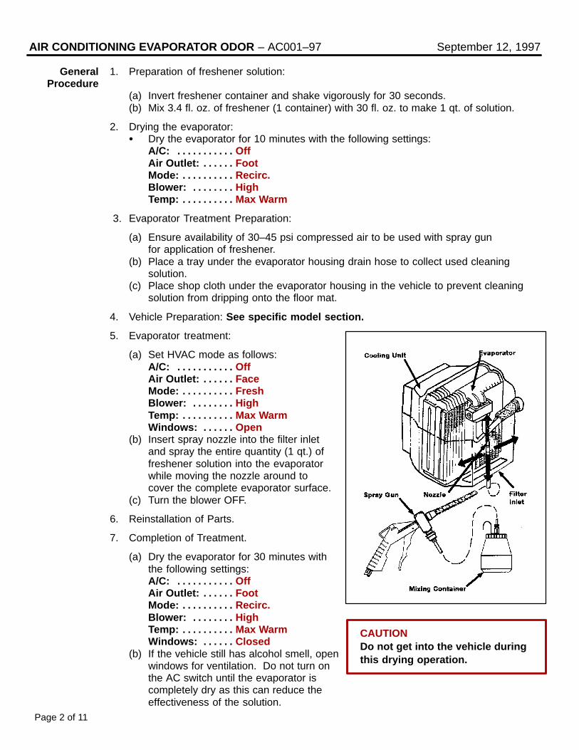
AIR CONDITIONING EVAPORATOR ODOR – AC001–97 September 12, 1997
General 1. Preparation of freshener solution:Procedure
(a) Invert freshener container and shake vigorously for 30 seconds.(b) Mix 3.4 fl. oz. of freshener (1 container) with 30 fl. oz. to make 1 qt. of solution.
2. Drying the evaporator: Dry the evaporator for 10 minutes with the following settings:
A/C: Off. . . . . . . . . . . Air Outlet: Foot. . . . . . Mode: Recirc.. . . . . . . . . . Blower: High. . . . . . . . Temp: Max Warm. . . . . . . . . .
3. Evaporator Treatment Preparation:
(a) Ensure availability of 30–45 psi compressed air to be used with spray gunfor application of freshener.
(b) Place a tray under the evaporator housing drain hose to collect used cleaning solution.
(c) Place shop cloth under the evaporator housing in the vehicle to prevent cleaning solution from dripping onto the floor mat.
4. Vehicle Preparation: See specific model section.
5. Evaporator treatment:
(a) Set HVAC mode as follows:A/C: Off. . . . . . . . . . . Air Outlet: Face. . . . . . Mode: Fresh. . . . . . . . . . Blower: High. . . . . . . . Temp: Max Warm. . . . . . . . . . Windows: Open. . . . . .
(b) Insert spray nozzle into the filter inletand spray the entire quantity (1 qt.) offreshener solution into the evaporatorwhile moving the nozzle around tocover the complete evaporator surface.
(c) Turn the blower OFF.
6. Reinstallation of Parts.
7. Completion of Treatment.
(a) Dry the evaporator for 30 minutes withthe following settings:A/C: Off. . . . . . . . . . . Air Outlet: Foot. . . . . . Mode: Recirc.. . . . . . . . . . Blower: High. . . . . . . . Temp: Max Warm. . . . . . . . . . Windows: Closed. . . . . .
(b) If the vehicle still has alcohol smell, openwindows for ventilation. Do not turn on the AC switch until the evaporator iscompletely dry as this can reduce the effectiveness of the solution.
Page 2 of 11
CAUTIONDo not get into the vehicle during this drying operation.

Page 3 of 11
AIR CONDITIONING EVAPORATOR ODOR – AC001–97 September 12, 1997
ES 300 1. Removal of parts.(’92–’96)
(a) Pull down the carpet from the centerconsole as indicated by red arrow in theillustration.
(b) Remove the plate on the side of theheater unit using steps and , indicated with red arrows to showdirection, in the illustration.
CAUTION:Do not bend the cable.
NOTE:The Plate will be reused.
(c) Remove the filter.
(d) Remove the blower controller.
2. Clean the Evaporator.
Follow the general procedures givenon page 2.
NOTE:Location for insertion of spray nozzleis indicated by the red arrow in the illustration.

AIR CONDITIONING EVAPORATOR – AC001–97 September 12, 1997
ES 300 3. Reinstallation of parts.(’92–’96)
(Continued) (a) Insert the filter (up side) into theheater unit following the numberedsteps shown in the illustration.
(b) Insert the filter (down side) into theheater unit.
(c) Reinstall the plate on the side of theheater unit using steps and ,indicated with red arrows to showdirection, in the illustration.
CAUTION:Confirm that the plate is secure.
(d) Restore the carpet to its originalposition taking care not to bendthe cable.
Page 4 of 11

Page 5 of 11
AIR CONDITIONING EVAPORATOR ODOR – AC001–97 September 12, 1997
GS 300 1. Removal of parts.
(a) Remove the undercover.
NOTE:Pull down the clip areas (3 places) of the Undercover to remove.
(b) Remove the lamp.
(c) Remove the (2) wing nuts and theplate on the bottom of the coolingunit.
CAUTION:The plate and wing nuts will be reused.
(d) Remove the (2) filters from the coolingunit.
2. Clean the Evaporator.
Follow the general procedures given onpage 2.
NOTE:Location for insertion of spray nozzle isindicated by the red arrow in the illustration.

AIR CONDITIONING EVAPORATOR ODOR – AC001–97 September 12, 1997
GS 300 3. Reinstallation of parts.(Continued)
(a) Insert the (2) filters into the coolingunit as shown in the illustration.
NOTE:Insert a clean air filter with it’s knobfacing downwards, then slide it forwardand install the second filter in the samemanner.
(b) Assemble the rubber insulator on theplate.
CAUTION:To prevent the cooling unit from leakingwater, pull the three rubber projectionsfrom the other side of the plate to makesure that the rubber insulator sealsproperly against the plate.
(c) Install the plate on the cooling unitand secure with the (2) wing nuts.
CAUTION:To prevent water leaks, verify that thecooling unit and plate are fully securebefore tightening the wing nuts.
NOTE:Before installing the plate on the coolingunit, coat the rubber insulator with waterfor easier assembly.
(d) Reinstall the lamp.
(e) Reassemble the Undercover.
Page 6 of 11

Page 7 of 11
AIR CONDITIONING EVAPORATOR ODOR – AC001–97 September 12, 1997
LS 400 1. Removal of parts.(’93–’94)
(a) Remove the undercover.
NOTE: Remove the front of “A” clips. Pull down the three “B” clip areas
of the Undercover to remove.
(b) Remove the lamp.
(c) Remove the (2) wing nuts and the plateon the bottom of the cooling unit.
CAUTION:The plate and wing nuts will be reused.
(d) Remove the (2) filters from the coolingunit.
2. Clean the Evaporator
Follow the general procedures given onpage 2.
NOTE:Location for the insertion of spraynozzle is indicated by the red arrow in the illustration.

AIR CONDITIONING EVAPORATOR ODOR – AC001–97 September 12, 1997
LS 400 3. Reinstallation of parts.(’93–’94)
(Continued) (a) Insert the (2) filters into the coolingunit as shown in the illustration.
NOTE:Insert a clean air filter with it’s knobfacing downwards, then slide it forwardand install the second filter in the samemanner.
(b) Assemble the rubber insulator on theplate.
CAUTION:To prevent the cooling unit from leakingwater, pull the three rubber projectionsfrom the other side of the plate to makesure that the rubber insulator sealsproperly against the plate.
(c) Install the plate on the cooling unit andsecure with the (2) wing nuts.
CAUTION:To prevent water leaks, verify that thecooling unit and plate are fully securebefore tightening the wing nuts.
NOTE:Before installing the plate on the cooling unit, coat the rubber insulator with water for easier assembly.
(d) Reinstall the lamp.
(e) Reassemble the Undercover.
Page 8 of 11

Page 9 of 11
AIR CONDITIONING EVAPORATOR ODOR – AC001–97 September 12, 1997
SC 300 1. Removal of parts.SC 400
(a) Remove two clips using the clipremover then remove the undercover.
NOTE:Pull down the clip areas (4 places) of the Undercover to remove.
(b) Remove the (2) wing nuts and the plateon the bottom of the cooling unit.
CAUTION:The plate and wing nuts will be reused.
(c) Remove the (2) filters from the coolingunit.
2. Clean the Evaporator
Follow the general procedures given onpage 2.
NOTE:Location for the insertion of spraynozzle is indicated by the red arrow in the illustration.

AIR CONDITIONING EVAPORATOR ODOR – AC001–97 September 12, 1997
SC 300 3. Reinstallation of parts.SC 400
(Continued) (a) Insert the (2) filters into the coolingunit as shown in the illustration.
NOTE:Insert a clean air filter with it’s knobfacing downwards, then slide it forwardand install the second filter in the samemanner.
(b) Assemble the rubber insulator on theplate.
CAUTION:To prevent the cooling unit from leakingwater, pull the three rubber projectionsfrom the other side of the plate to makesure that the rubber insulator sealsproperly against the plate.
(c) Install the plate on the cooling unit andsecure with the (2) wing nuts.
CAUTION:To prevent water leaks, verify that thecooling unit and plate are fully securebefore tightening the wing nuts.
NOTE:Before installing the plate on the cooling unit, coat the rubber insulator with water for easier assembly.
(d) Reassemble the Undercover.
Page 10 of 11
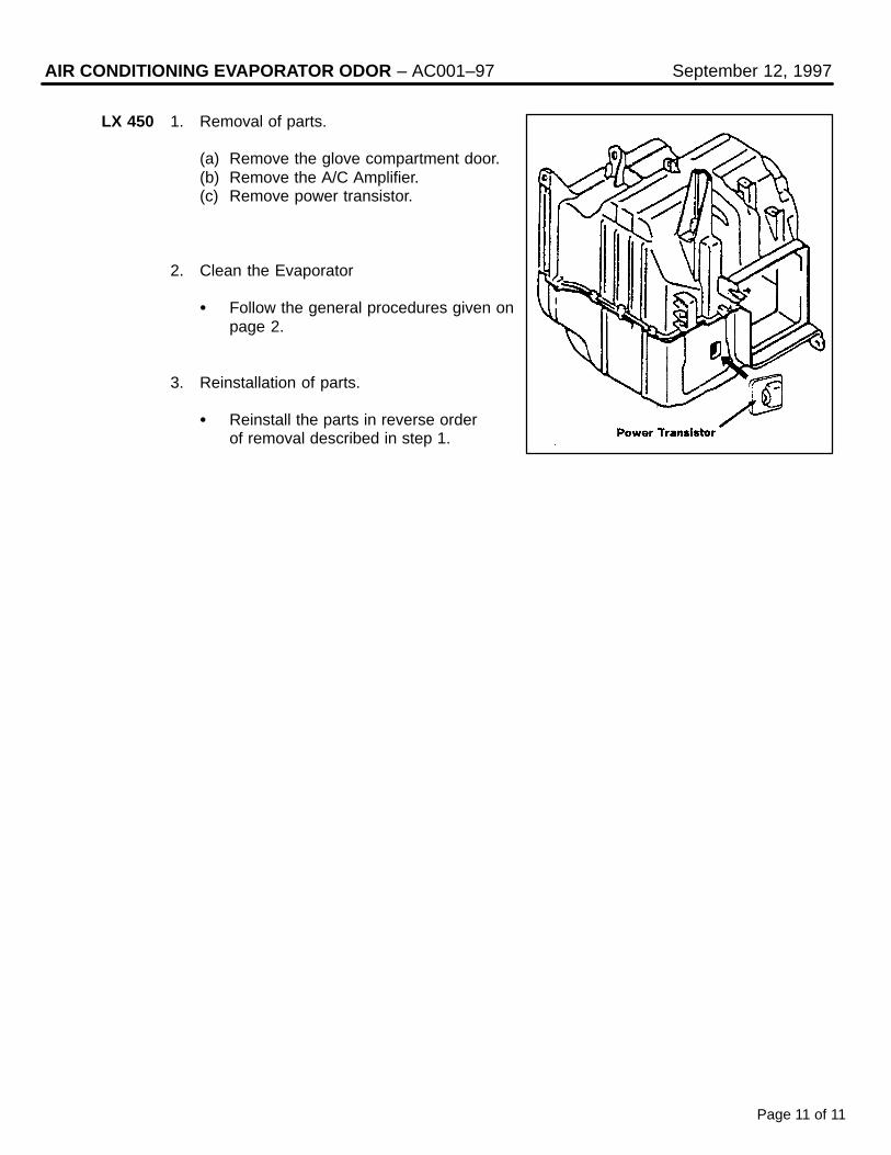
Page 11 of 11
AIR CONDITIONING EVAPORATOR ODOR – AC001–97 September 12, 1997
LX 450 1. Removal of parts.
(a) Remove the glove compartment door.(b) Remove the A/C Amplifier.(c) Remove power transistor.
2. Clean the Evaporator
Follow the general procedures given onpage 2.
3. Reinstallation of parts.
Reinstall the parts in reverse orderof removal described in step 1.

DATE: JUNE 7, 1996
Title A/C COMPRESSOR MAINTENANCE FOR STORED VEHICLES Page 1 of 1
When a vehicle is stored for a long period, the volume of oil in the A/C compressor may decrease due to oil flow into the condenser, pipes, etc.
If the A/C system is turned on at high engine RPM after a long storage period, A/C compressor damage may result.
To minimize the possibility of damage to the A/C compressor while storing a vehicle, perform the following recommended procedure at least once a month to lubricate the compressor.
RECOMMENDED PROCEDURE FOR A/C COMPRESSOR LUBRICATION :
1. Turn off A/C And blower switches prior to starting engine.
2. Start and warm–up engine until engine speed drops below 1,000 RPM.
3. Turn on the A/C system using the following settings:
A/C switch: On
Blower Speed: High
Engine speed: Below 1,000 RPM
4. Keep A/C on with engine idling for 30 seconds.
5. Turn off A/C system and stop engine.
REF: HEATING & AIRCONDITIONING
NO: AC003-96
MODEL: ALL MODELS

DATE: AUGUST 23, 1996
Title STATIC NOISE ON WEAK AM STATIONS Page 1 of 3
REF: AUDIO
NO: AU001–96
MODEL: ALL MODELS
Some Lexus audio systems may exhibit audible electrical noise on weak AM stations when variouselectrical accesssories (turn signals, rear defogger, cruise control, brakes, etc.) are operated.
Poor antenna grounding can cause this condition.
To eliminate or reduce the intensity of the noise use the following repair procedure:
REPAIR PROCEDURE:
1. Play the radio on a strong, static–free AMstation and slowly move the tip of the an-tenna mast forward and back approximately2 inches (Fig. 1). If static noise is notheard, go to Step 2. If static noise is heardduring antenna movement, replace the an-tenna mast and go to Step 3.
NOTE: Do not touch the antenna mast withyour bare hands. Use a glove or non-metallic object to move the antenna. (Ifyou touch the antenna with your hands,you will change the antenna sensitivity).
2. Remove the antenna mast and inspect thebase of the mast for corrosion and damage.Clean with 1500 grit sandpaper (Fig. 2).
3. Remove the antenna assembly and in-spect the inner fender around the antennahole for corrosion. Clean with 1500 gritsandpaper (Fig. 3).
ÇÇÇÇÇÇÇÇ
Fig. 1
ÇÇÇÇÇÇÇÇ
Fig. 2
InspectionArea
ÇÇÇÇÇÇÇÇÇÇÇÇ
Fig. 3

STATIC NOISE ON WEAK AM STATIONS Page 2 of 3
REPAIR PROCEDURE (Cont’d ):
4. Remove the antenna spacer grommet atthe top of the antenna assembly and in-spect for corrosion. Clean with 1500 gritsandpaper ( Fig. 4).
5. Reinstall the antenna assembly. Be sure toinstall the external antenna nut (escutch-eon) first. Then install the nut which holdsthe assembly to the inner bracket ( Fig. 5).
6. Check to make sure that the teeth on theantenna spacer grommet make good con-tact with the inner fender well (Fig. 6).
7. Inspect the antenna cable connection andclean as necessary. Reconnect the anten-na cable, the wire harness and the drainhose (Fig. 7).
ÇÇÇÇÇÇÇÇ
Fig. 4
ÇÇÇÇÇÇÇÇÇÇ
InspectionArea
ÇÇ1
ÇÇÇÇÇÇÇÇ
Fig. 5Push
ÇÇ
ÇÇ
2
3
ÇÇÇÇÇÇÇÇÇÇÇÇ
Fig. 6
ÇÇÇÇÇÇÇÇ
Teeth
ÇÇÇÇÇÇÇÇAntenna
ÇÇÇÇÇÇÇÇ
Fender
ÇÇÇÇÇÇÇÇ
Fig. 7
ÇÇÇÇÇÇÇÇÇÇÇÇÇÇÇ
InspectionArea

STATIC NOISE ON WEAK AM STATIONS Page 3 of 3
WARRANTY INFORMATION:
ÇÇÇÇÇÇÇÇÇÇ
OPCODEÇÇÇÇÇÇÇÇÇÇÇÇÇÇÇÇÇÇÇÇÇÇÇÇÇÇÇÇ
DESCRIPTIONÇÇÇÇÇÇÇÇ
TIMEÇÇÇÇÇÇÇÇÇÇÇÇÇÇÇÇÇÇÇÇÇÇ
OPNÇÇÇÇÇÇÇÇ
T1ÇÇÇÇÇÇ
T2
EL5001Listed TSIB repair procedure
(All Items)1.0 86300–XXXXX 76 73

TSIBIntroduction The cassette tape head and capstan should be cleaned regularly to prevent poor sound
quality and/or cassettes from jamming.
AU
DIO
May 16, 1997
Title:
CLEANING CASSETTE TAPE HEADSAND CAPSTANSModels:
All Models
Page 1 of 2
AU
001–97
RE
VIS
ED
Conditions The following conditions can easily be avoided by regularly cleaning the head with a tapecleaner and only using good quality cassettes.
Poor Sound Since the tape head contacts the cassette tape, the tape head accumulates metal oxidesQuality due to and dirt particles from the tape. In time, a layer of dirt forms on the tape head resulting in
Dirty Head poor transfer of information between the tape and the tape head. This typically causes areduction of higher frequencies or a reduction of the brightness in sound quality.
Tape Speed Tape speed is controlled by the tape capstan and pinch rollers. If the capstan and pinchrollers accumulate dirt, the tape may slip causing the music to play too fast or too slow.
Jamming Dirt can make the capstans sticky, causing the tape to become entangled in the cassettemechanism. This can cause the cassette to become jammed in the player.
Cassette To reduce the occurrence of these conditions, the following approved cassette cleaners areTape Head available through the non–parts system (Material Distribution Center).
Cleaners
TOOLS & MATERIALS MATERIAL NUMBER DESCRIPTION
Allsop 3 Cassette Recorder Cleaner 00113–AS710–00 Cleaning Cassette and CleaningSolution with Instruction Sheet
NOTE:Allow 15 minutes for the cleaning fluid to evaporate before playing a tape.
Fig. 1

CLEANING CASSETTE TAPE HEADS AND CAPSTANS – AU001–97 (Revised) May 16, 1997
Cassette The following precautions should be taken to keep cassettes in good condition:Tape CareProcedure 1. Remove the cassette from the player when the cassette is not in use.
2. Store the cassette in its case.
3. Store the cassette in a cool, dry area away from direct sunlight and magnetic componentssuch as speakers.
4. Avoid touching the tape itself. This could result in poor sound quality or sound drop out.
5. Keep the tape tightly wound as shown infigure 2. Tape speed can be affected byloosely wound tape.
6. Avoid inserting a cassette into the player ifthe cassette label is loose or peeling asshown in figure 3. This can cause acassette to become stuck in the player.
7. Use cassettes that are 90 minutes or lessin length. Cassettes over 90 minutes useextremely thin tape that is subject to stretch, resulting in poor sound quality.
Page 2 of 2
Fig. 2
Fig. 3
Fig. 4

2297 x 150 (T = 3.0)
TSIBIntroduction A kit containing special foam sponge material has been developed. This kit, when used
in conjunction with procedures outlined in the Interior and Wind Noise Diagnosis Manual(P/N 00246-30015) and Lexus Service Information Bulletins, should enable effectivewind noise repairs.
Affected • All ModelsVehicles
BO
DY
February 21, 1997
Title:
WIND NOISE REPAIR KITModels:
All Models
Page 1 of 1
BO
001-97
PART NUMBER PART NAME QTY
0823100810 Kit, Wind Noise 1
Caulking Sponge Sealant No. 1 2
SIZE (MM)
297 x 150 (T = 3.0)
- - -
0823100811*
Caulking Sponge Sealant No. 2 2297 x 150 (T = 5.0)0823100812*
Caulking Sponge Sealant No. 3 2297 x 150 (T = 10.0)0823100813*
Caulking Sponge Sealant No. 40823100814*
Caulking Sponge Sealant No. 5 2297 x 150 (T = 5.0)0823100815*
Caulking Sponge Sealant No. 6 2297 x 150 (T = 5.0)0823100816*
Kit 1. Caulking Sponge Sealant No. 1, No. 2Components and No. 3 (Ept-sealer).
2. Caulking Sponge Sealant No. 4 and No. 5(Ept-sealer). This sheet is divided into27 strips, 5 mm wide.
3. Caulking Sponge Sealant No. 6 (Ept-sealer).
PartsInformation
* All of these parts are included in the kit.

Title STAINS ON RAPGARD APPLIED AREAS Page 1 of 1
On some Lexus models, when Rapgard is removed from the vehicle, a stain is left on the paint sur-face. This stain can be seen under the clear coat and is not a defect of the clear coat. The stain cor-responds to a wrinkled area of Rapgard which retained liquids, such as window washer fluid, that lefta discoloration.
REPAIR PROCEDURE:
To remove a stain from a vehicle, heat the stain surface to a temperature of 70C – 80C. When thestain is removed it will not reappear.
Equipment –1. Infrared lamp or dryer to heat the surface.2. Aluminum foil or a damp cloth to protect plastic parts from deformation.
Procedure –1. Apply aluminum foil to adjoining plastic parts or cool with damp cloth periodically.2. Use an infrared lamp or dryer on the stain developed area and heat for 5 to 10 minutes at
70C – 80C.3. After heating for 5 minutes, check whether the stain has disappeared. If the stain still
remains, reheat the area and check again.
NOTE: Take care that the body’s paint surface temperature does not become too high.
WARRANTY INFORMATION:
REF: BODY
NO: BO002–96
MODEL: ALL MODELS
OPCODE DESCRIPTION TIME OPN T1 T2
BD6004 Remove stains from paint surface caused by Rapgard
0.6 61 9953301–XXXXX
DATE: AUGUST 9, 1996

Title SEAT BELT EXTENDERS FOR 1993 THROUGH 1997 MODELS Page 1 of 6
Lexus customers who find it necessary to increase the length of their seat belts may obtain Seat BeltExtenders at no cost through their local Lexus dealer.
The extender is available in black only, in 6, 9, 12, 15 and 18 inch lengths.
Owners are informed of the seat belt extender availability through the Lexus Owner’s Manual included in each vehicle.
The customer (individual requiring the extender) must visit a Lexus Dealership to have the requiredmeasurements made and to complete the seat belt extender worksheet. The worksheet will allow theproper fitting and selection of a seat belt extender for the customer. The dealership personnel should thendetermine the applicable part number and place a Critical Order through the TDN Parts Network.
Included in this bulletin is the information covering the1993 through 1997 model years:
The dealership service department should complete the affixed Seat Belt Extender Label and review the“owner instruction sheet” with the customer. The dealership should give a copy of the completed work-sheet to the customer and keep the original in the customer’s file.
To assure utmost owner satisfaction, it is recommended that a dealership designate one person to coordi-nate all activities related to the seat belt extender issue.
From past sales history, it is recommended that dealerships do not stock seat belt extenders due to lowdemand and the need for customer fitting.
REF: BODY
NO: BO003–96
MODEL: ALL MODELS
Contents Page
Flow Chart 2
Application/Part Number 3
Owner Instruction Sheet 4
5
6
Statement from Owner’s Manual
Seat Belt Extender Worksheet
DATE: NOVEMBER 15, 1996

SEAT BELT EXTENDER FOR 1993 THROUGH 1997 MODELS Page 2 of 6
PROCEDURE:
1. Owner requests a seat belt extender from the dealer.
2. Dealer verifies the need for a seat belt extender, obtains a current copy of the TSB, and copies the worksheet.
3. Dealer measures the customer and completes the worksheet. Dealer determines the correct part number and places a Critical Order for the part through the TDN Parts Network.
4. Dealer receives the seat belt extender and calls the customer in to check fit of the part.
5. If the seat belt extender fit is OK, dealership personnel complete the customer information label on the part, explains usage of the part to customer, then gives customer a copy of the completed worksheet.
6. Dealer places a copy of the completed worksheet in the customer’s records.
SAMPLE SEAT BELT LABEL:
DEALER PARTS DEALER OWNER
SUPPLY
MEASURE
CUSTOMER &
COMPLETE
WORKSHEET
PLACE
CRITICAL
ORDER
THROUGH
TDN
SHIP SEAT
BELT
EXTENDER
TO DEALER
TEST FIT
CUSTOMER
WITH PART
COMPLETE
LABEL AND
ADVISE
OWNER
RECEIVE
COPY OF
WORKSHEET
& USE
EXTENDER
FILE
WORKSHEET
IN CUSTOMER
RECORDS
SEAT BELT EXTENDER (SBE) FLOW CHART

PART NUMBER INFORMATION:
Locate the series code on the series application charts, then use the part number by length chart toidentify the correct part number for the specific customer.
FRONT SEAT EXTENDER SERIES APPLICATION TABLE:
REAR SEAT EXTENDER SERIES APPLICATION TABLE:
NOTE: *The extender must not be used for the center rear seat belt (except ‘97 model ES 300 as noted in the chart).**Includes third seat application.
PART NUMBER BY REQUIRED LENGTH (73399–):
SEAT BELT EXTENDER FOR 1993 THROUGH 1997 MODELS Page 3 of 6
Model 1997 1996 1995 1994 1993
LS 400 R-3 R-3 R-3 R-3 R-3
GS 300 N-3 N-3 N-3 N-3 N-3
SC 400 R-3 R-3 R-3 R-3 R-3
SC 300 R-3 R-3 R-3 R-3 R-3
ES 300 R-5 K-4 K-4 K-4 K-4
LX 450 R-3 R-3 - - -
Model 1997 1996 1995 1994 1993
LS 400 R-3 R-3 R-3 R-3 R-3
GS 300 K-4 K-4 K-4 K-4 K-4
SC 400 R-3 R-3 R-3 R-3 R-3
SC 300 R-3 R-3 R-3 R-3 R-3
ES 300.. Right & Left R-5 R-3 R-3 R-3 R-3
ES 300..Center R-3* - - -
LX 450 K-4**
-
K-4** - - -
SERIES 6 INCH 9 INCH 12 INCH 15 INCH 18 INCH
K-4
N-3
R-3
R-5
33010
20011
50010
16060
33020
20021
50020
16070
33030
20031
50030
16080
33040
20041
50040
16090
33050
20051
50050
16100

SEAT BELT EXTENDER FOR 1993 THROUGH 1997 MODELS Page 4 of 6
OWNER INSTRUCTION FOR PERSONALIZED SEAT BELT EXTENDER:
CAUTION FOR USE OF SEAT BELT EXTENDERS:
1. Never use the seat belt extender if you can fasten the seat belt without it.
2. Remember the seat belt extender provided for you may not be safe when used in a different vehicle, or for another person or at a seating position different than specified.
3. When the seat belt extender is provided for a rear seat position (with automatic locking retractor), make sure the retractor is locked when in use.
4. FAILURE TO FOLLOW THESE INSTRUCTIONS COULD RESULT IN A LESS EFFECTIVE SEAT BELT RESTRAINT SYSTEM IN CASE OF A VEHICLE ACCIDENT, CAUSING PERSONAL INJURY.
USING THE SEAT BELT EXTENDER:
1. Connect the seat belt extender to the seat belt by inserting the tab into the seat belt buckle so the bucklerelease buttons of the seat belt extender and the seat belt are located on the same side as shown in the illustration. You will hear a click when the tab properly locks into the buckle.
2. MAKE SURE THAT THE CONNECTION IS SECURE AND THE SEAT BELT EXTENDER IS NOT TWISTED.
3. When releasing the seat belt, press on the buckle release button on the seat belt extender, not on the seat belt. This helps prevent damage to the vehicle interior and seat belt extender.
4. When not in use, remove the extender and store in the vehicle.

SEAT BELT EXTENDER FOR 1993 THROUGH 1997 MODELS Page 5 of 6
OWNER’S MANUAL TEXT:
SEAT BELT EXTENDER
If your seat belt cannot be fastened securely because it is not long enough, a personalized seat belt ex-tender is available from your Lexus dealer free of charge.
Please contact your local Lexus dealer so that the dealer can order a seat belt extender of the proper re-quired length. Bring the heaviest coat you expect to wear for proper measurement and selection of length.Additional ordering information is available at your Lexus dealer.
CAUTION:
When using the seat belt extender, observe the following. Failure to follow these instructions could result inless effectiveness of the seat belt restraint system in case of a vehicle accident, increasing the chance ofpersonal injury.
Never use the seat belt extender if you can fasten the seat belt without it.
Remember that the seat belt extender provided for you may not be safe when used on a different vehicle, or for another person and/or at different seating positions than specified.
To connect the seat belt extender to the seat belt, insert the tab into the seat belt buckle so that the buckle release buttons of the seat belt extender and the seat belt are both facing outward as shown.
You will hear a click when the tab locks into the buckle. When releasing the seat belt, press on the buckle–release button on the seat belt extender, not on the seat belt. This helps prevent damage to the vehicle in-terior and seat belt extender itself.
When not in use, remove the seat belt extender and store in the vehicle for future use.
CAUTION:
After inserting the tab, make sure that the connection is secure and the seat belt extender is nottwisted.


TSIBIntroduction Lexus implemented a production change to eliminate a noise in the ashtray receptacle.
The receptacle now has 2 additional ribs eliminating a buzzing noise between the ashtray insert and receptacle.
BO
DY
April 4, 1997
Title:
FRONT ASHTRAY RECEPTACLE BUZZNOISEModels:
‘97 ES 300
Page 1 of 1
BO
003-97
Production • 1997 ES 300 starting with VIN JT8BF22G#V0008640Change
Information
Applicable Warranty :3 years or 36,000 miles.
Field-Fix 1. Remove the ashtray insert.Procedures
2. Install 1 piece of felt to each rib of theashtray insert.
Use felt size of 10 x 40 x 0.5 mm toeach rib.
NOTE:Confirm that the ashtray insert is fully seated in the receptacle afterthe field-fix procedure is completed.
WarrantyInformation
OPCODE DESCRIPTION TIME OPN T1 T2
BD7006 Ashtray Receptacle Assembly 0.2 7411033060 91 57

Title AIR LEAK NOISE FROM FRONT DOOR GLASS AT LOWER REAR CORNER Page 1 of 2
To prevent a possible air leak (sometimes described as wind noise) at the lower rear corner of thefront door glass, TMC implemented a production change to the interior door trim panel improving theseal between the door glass and door weather strip. The revised trim panel applies light additionalpressure on the weather strip effectively eliminating an air leak at the #4 corner.
PRODUCTION EFFECTIVE:
Starting VIN: JT8BF22G * V0012715
FIELD–FIX METHOD:
Apply hand pressure at the top rear of the front door weather strip to eliminate any gap (“A”) between the edge of the glass and weather strip.
While sitting in the driver seat, close the door. Make certain it is closed completely.
REF: BODY
NO: BO004–96
MODEL: ES 300
DATE: DECEMBER 6, 1996

AIR LEAK NOISE FROM DOOR GLASS AT #4 CORNER Page 2 of 2
FIELD–FIX METHOD (CONT’D):
Measure the gap between the weather strip (“B”) and the door glass at the lower rear inside corner of theglass.
Apply a thickness of foam tape equal to the measured gap plus 1 mm to the door weather strip rubber plate. Pull the weather strip rearward far enough to expose the plate, then apply foam tape (7 mm x 14 mm) to the rubber plate.
After foam tape is applied to the rubber plate, push the weather strip back into its fully seated position. No gaps should exist at edge of glass or inside of glass at weatherstrip.
CAUTION: Apply only a thickness of foam tape as necessary to eliminate the gap. Using more than the measured amount will interfere with the normal operation of the weather strip to glass in the full down position.
WARRANTY INFORMATION:
Applicable Warranty Coverage: 4 years/50,000 miles Comprehensive Warranty.
OPCODE DESCRIPTION TIME OPN T1 T2
BD6009Air leak Noise from front doorglass at lower rear corner (#4) 0.5 59 57
68173–33020 (RH)68174–33010 (LH)

TSIBIntroduction On some 1997 ES 300 vehicles, a rattle noise from the moon roof sliding rail assembly
may be evident. If the noise exists, it is most apparent driving over highway type dotswith the moon roof open approximately 100 mm.
Two changes were implemented:
• Increased viscosity of the grease at the front shoe pin.
• Stiffened the rubber cushion on the siding rail.
BO
DY
May 30, 1997
Title:
MOON ROOF RATTLE ON 1997 ES 300Models:
‘97 ES 300
Page 1 of 2
BO
004-97
ProductChange
Information
VIN
JT8BF22G * V0003340
PRODUCTION CHANGE
Increased Grease Viscosity
JT8BF22G * V0048965 Stiffened Rubber Cushion
Parts NOTE:Information Part numbers remain unchanged.
WarrantyInformation
OPCODE DESCRIPTION TIME OPN T1 T2
BD7008
Moon Roof Panel R&R andinstall adhesive back felt tapeand grease (both sides), verify
condition resolved
0.6 6320133050 91 43

MOON ROOF RATTLE ON 1997 ES 300 – BO004-97 (Revised) May 30, 1997
Field-Fix Verify the concern by either road test or static check (static check is to open moonProcedures roof approximately 100 mm, then tap lightly by hand on front edge of panel).
If a rattle exists, correct this condition by following the field-fix procedures outlinedbelow:
• Remove the moon roof glass panel by first removing the black plastic covers at thebase of the moon roof glass on both right and left sides.
NOTE:This must be done from inside the vehicle.
• Remove the (4) attaching torx head screws holding the moon roof glass panel inplace.
• Carefully remove the moon roof glass panel and store it in the trunk while makingrepairs.
• Use the electric switch to place the assembly in the TILT UP position.
• clean the light gray rubber stop, with a VOC compliant wax and grease removerapproved for use in your area. (Check local regulations.)
• Place adhesive back felt tape (W: 10 mm,L:15 mm, T:5 mm) on the rubber stop(both sides).
• Apply high viscosity grease (P/N00289-1WG00 or equivalent) to the frontshoe pin.
• Engage the electric switch returning theassembly to the neutral position.
• Reinstall the moon roof glass panel andmake the appropriate flushnessadjustments before tightening theattaching screws.
Flush adjustment specifications:
±1.5 mm at front (overflush)0 + 1.5 mm at rear (overflush)0 – 1.0 mm at rear (underflush)
• Engage the electric switch moving the moon roof panel rearward approximately 100 mm.
• Check for a rattle by tapping lightly (static check) on the front edge of the moon roofglass panel.
• Torque the attaching screws according to the repair manual.
• Reinstall the plastic covers.
• Test drive the vehicle to confirm no noise exists.
Page 2 of 2

TSIBIntroduction Some 1997 ES 300s may exhibit a “popping” noise emitting from the rear of the vehicle,
especially when turning left or right ar low speeds (10 to 20 m.p.h.) or when going overspeed bumps. This noise may be caused by insufficient “V–Brace” weld nut and bolt torque.
BO
DY
July 25, 1997
Title:
V–BRACE REAR POPPING NOISEModels:
’97 ES 300
Page 1 of 1
BO
005–97
Affected 1997 ES 300sVehicles
Required 3/8” Ratchet with 8” Extension Bar Slotted Screw DriverTools & 12 mm Deep Well Socket Thread Lock Adhesive (Locktite 242).
Materials Torque Wrench
Warranty OPCODE DESCRIPTION TIME OPN T1 T2
Information710041 Rear Seat Back Assembly 0.3 64241–33010 62 81
Applicable Warranty:This repair is covered under the Lexus Comprehensive Warranty. This warranty
is in effect 48 months or 50,000 miles, whichever occurs first, from the vehicle’sin–service date.
Repair 1. Remove the rear seat.Procedure
NOTE:Refer to the Repair Manual (Page BO–86)for seat removal and installation.
2. Remove the 4 set nuts and 2 bolts andapply thread lock adhesive to thethreads.
3. Torque the set nuts and bolts on the“V–Brace.”
Torque: 13 ft lbf (18 N m, 185 kgf cm)
4. Reinstall the rear seat.
5. Confirm the condition has beenrepaired by test driving.

TSIBIntroduction Some ES 300 models may experience the lower dash under cover (below glove
compartment) coming loose and/or falling off. The main engine wire harness routing wasmodified to prevent excessive down force on the under cover.
Production 1997 ES 300s starting with VINs JT8BF22G*V0039230Change
Information
Warranty OPCODE DESCRIPTION TIME OPN T1 T2
InformationBD7017 Move engine wire harness under lower dash 0.5 55607–33040 62 99
Applicable Warranty:This repair is covered under the Lexus Comprehensive Warranty. This warrantyis in effect for 48 months or 50,000 miles, whichever occurs first, from the vehicle’s in–service date.
RepairProcedure NOTE:
Refer to the ES 300 Repair Manual (Page RS–19) in addition to the illustrations below.
1. Remove the lower dash under cover(No. 2 Under Cover), front door scuffplate and glove compartmentassembly (Lower Instrument Panel) asshown in the repair manual.
NOTE:DO NOT disconnect yellow SRSJunction Block.
2. Move the Engine Control Module(ECM) to the right in order to gainclearance between the blower unitjunction block and the ECM.
BO
DY
September 5, 1997
Title:
DASH UNDER COVER LOOSE/FALLINGModels:
’97 ES 300
Page 1 of 2
BO
006–97

DASH UNDER COVER LOOSE/FALLING – BO006–97 September 5, 1997
Repair 3. Reposition the engine wire harness byProcedure lifting it up between the ECM and the
(Continued) blower unit. Position the engine wireharness on the right side end of theblower junction block as shown.
Page 2 of 2
4. If necessary, move the ECM back toit’s original position.
5. Reinstall the glove compartmentassembly, front door scuff plate andclip the SRS junction connector backinto position on the lower dash undercover (No. 2 Under Cover). Carefullyreinstall the lower dash cover, takingcare that the rear locating pin and theright rear locating tab are correctly positioned.

TSIBIntroduction Lexus customers who find it necessary to increase the length of their sear belts may
obtain Seat Belt Extenders at no cost through their local Lexus dealer.
The extender is available in 6 inch, 9 inch, 12 inch, 15 inch and 18 inch lengths.
The extender is available only in black .
Owners are informed of the seat belt extender availability through the Lexus Owner’sManual included in each vehicle.
The customer (individual requiring the extender) must visit a Lexus dealership to have therequired measurements made and to compete the seat belt extender worksheet. Theworksheet will allow the proper fitting and selection of a seat belt extender for thecustomer. The dealership personnel should then determine the applicable part numberand place a Critical Order through the TDN Parts Network .
The dealership service department should compete the affixed Seat Belt Extender Labeland review the “owner instruction sheet” with the customer. The dealership should givea copy of the completed worksheet to the customer and keep the original in the customer’s file.
To assure utmost owner satisfaction, it is recommended that a dealership designate oneperson to coordinate all activities related to the seat belt extender issue.
From past sales history, it is recommended that dealerships do not stock Seat belt extenders due to low demand and the need for customer fitting.
This bulletin contains the following information:Procedure and Flow Chart Page 2. . . . . . . . . . . . . Application Chart and Notes Page 3. . . . . . . . . . . Part Number Information Page 3. . . . . . . . . . . . . . . Owner Instructions Page 4. . . . . . . . . . . . . . . . . . . . Seat Belt Extender Worksheet Page 5. . . . . . . . . .
Affected All Lexus models, 1994 through 1998 model years.Vehicles
Warranty OPCODE DESCRIPTION TIME OPN T1 T2
InformationN/A Not applicable to warranty – – – –
BO
DY
October 24, 1997
Title:
SEAT BELT EXTENDERSModels:
All ’94 through ’98 models
Page 1 of 5
BO
007–97

SEAT BELT EXTENDERS: 1994–1998 – BO007–97 October 24, 1997
Procedure 1. Owner requests a seat belt extender from dealer.
2. Dealer verifies the need for a seat belt extender and obtains a current copy of this TSB and copies the worksheet.
3. Dealer measures the customer and completes the worksheet. Dealer determinesthe correct part number and places a Critical Order for the part through the TDNParts Network.
4. Dealer receives seat belt extender and calls the customer in to check fit of the part.
5. If the seat belt extender fit is good, dealership personnel completes the customerinformation label on the part, explains usage of the part, and gives the customer acopy of the completed worksheet.
6. Dealer places a copy of the completed worksheet in the customer’s records.
Page 2 of 5

Page 3 of 5
SEAT BELT EXTENDERS: 1994–1998 – BO007–97 October 24, 1997
Front SeatBelt ExtenderApplications
FRONT SEAT - EXTENDER APPLICATION
MODEL '98 '97 '96 '95 '94
LS 400 R–3 R–3 R–3 R–3 R–3
GS 400 R–5 N/A N/A N/A N/A
GS 300 R–5 N–3 N–3 N–3 N–3
SC 400 R–3 R–3 R–3 R–3 R–3
SC 300 R–3 R–3 R–3 R–3 R–3
ES 300 R–5 R–5 K–4 K–4 K–4
LX 450 N/A R–3 R–3 N/A N/A
Rear SeatBelt ExtenderApplications
REAR SEAT - EXTENDER APPLICATION
MODEL '98 '97 '96 '95 '94
LS 400 R–3 R–3 R–3 R–3 R–3
GS 400 N/A N/A N/A N/A
GS 300 K–4 K–4 K–4 K–4
SC 400
SC 300
ES 300 (Right & Left) R–5 R–5 R–3 R–3 R–3
ES 300 (Center) R–3 R–3* N/A N/A N/A
LX 450 N/A K–4** K–4** N/A N/A
R–3 R–3 R–3 R–3 R–3
K–5
NOTE:* The extender must NOT be used for the center rear seat belt (except on ’97
and ’98 model ES 300s as noted in the chart).** Includes third seat application.
PartsInformation
PART NUMBER PREFIX: 73399-
LENGTH
6 INCH 9 INCH 12 INCH 15 INCH 18 INCH
K–4 –33010 –33020 –33030 –33040 –33050
K–5 –35010 –35020 –35030 –35040 –35050
N–3 –20011 –20021 –20031 –20041 –20051
R–3 –50010 –50020 –50030 –50040 –50050
R–5 –16060 –16070 –16080 –16090 –16100
SERIES

SEAT BELT EXTENDERS: 1994–1998 – BO007–97 October 24, 1997
Owner Failure to follow the recommendations indicated below could result in lessInstructions effectiveness of the seat belt restraint system in case of vehicle collision, causing
personal injury.
The seat belt extender must not be used:
a. By anyone other than for whom it was provided (name recorded on seat beltextender).
b. In any vehicle and/or seat position other than the one for which it was provided.
c. When the seat belt extender is provided for rear seat positions (with automaticlocking retractor), make sure the retractor is locked when is use.
If your seat belt cannot be fastened securely because it is not long enough, a personalized seat belt extender is available from your Lexus dealer free of charge.
Please contact your local Lexus dealer so that the dealer can order the properrequired length for the extender. Bring the heaviest coat you expect to wear for propermeasurement and selection of length. Additional ordering information is available at yourLexus dealer.
CAUTION:
When using the seat belt extender, observe the following. Failure to follow theseinstructions could result in less effectiveness of the seat belt restraint system incase of vehicle accident, increasing the chance of personal injury.
Never use the seat belt extender if you can COMFORTABLY fasten the seat beltwithout it.
Remember that the extender provided for you may not be safe when used ona different vehicle, or for another person or at a different seating position thanthe one originally intended for.
To connect the extender to the seatbelt, insert the tab into the seat beltbuckle so that the “PRESS” signs onthe buckle–release buttons of theextender and the seat belt are bothfacing outward as shown.
You will hear a click when the tab locksinto the buckle.
When releasing the seat belt, press onthe buckle–release button on theextender, not on the seat belt. This helpsprevent damage to the vehicle interiorand extender itself.
When not in use, remove the extender and store in the vehicle for future use.
Page 4 of 5


DATE: APRIL 19, 1996
Title EXHAUST PIPE PROTECTOR AND CLAMP Page 1 of 1
For ES 300s with 1MZ–FE engines, exhaust pipe protectors and clamps are now available as separatesupply parts. Part numbers and installation instructions for these parts are provided below.
PART NUMBER INFORMATION:
REF: ENGINE
NO: EG002–96
MODEL: ES 300
NUMBER
1
2
3
4
5
6
7
8
9
PART NAME
Protector, Exhaust Pipe, Upper No. 2
Protector, Exhaust Pipe, Upper No. 3
Protector, Exhaust Pipe, Upper No. 4
Protector, Exhaust Pipe, Lower No. 2
Protector, Exhaust Pipe, Lower No. 3
Protector, Exhaust Pipe, Lower No. 4
Clamp
Clamp
Clamp
PART NUMBER
17522–20010
17523–20010
17524–62020
17594–20010
17595–20010
17596–62020
90461–12350
90461–12385
90461–12353
QUANTITY
1
1
1
1
1
1
1
1
1
REPLACEMENT PROCEDURE:
Install protector so there is no noticeable gap or interference between exhaust pipe and protector.
Torque: 100 kgf-cm (7ft-lbs)

DATE: OCTOBER 11, 1996
Title UNDERCOATING ON OXYGEN SENSORS Page 1 of 1
During vehicle processing by Dealers, care must be taken to avoid applying undercoating in the area sur-rounding the Oxygen Sensors. Application of undercoating on or near the Oxygen Sensors can causeinsufficient air to flow around the sensor, and inaccurate information storage by the ECM. If this conditionoccurs, the Malfunction Indicator Light (MIL) may illuminate.
REF: ENGINE
NO: EG004–96
MODEL: ALL MODELS

TSIBIntroduction To prevent contact between the tail pipe and heat shield when turning quickly and/or
going over bumps, the Exhaust Pipe Support No. 4 has been changed to prevent excessive movement of the tail pipe assembly.
EN
GIN
E
May 16, 1997
Title:
TAIL PIPE CONTACT WITH HEAT SHIELDModels:
’97 ES 300
Page 1 of 2
EG
005–97
Affected 1997 Model Year ES 300 produced before VIN JT8BF22G#V0021520 .Vehicles
Parts PREVIOUS PART NUMBER CURRENT PART NUMBER PART NAME
Information17565–20050 17565–11160 Support, Exhaust. Pipe No. 4
Warranty OPCODE DESCRIPTION TIME OPN T1 T2
Information170281 Exhaust pipe support bracket (for tailpipe) 0.4 17565–20050 91 57
Fig. 1
Fig. 2 Fig. 3

TAIL PIPE CONTACT WITH HEAT SHIELD – EG005–97 May 16, 1997
Repair 1. Remove original exhaust pipe supportProcedure No. 4 then loosen nuts (as indicated
by red arrows in figure 4) to turn theflange of the tail pipe.
2. Reposition muffler assembly by pullingdown tail pipe assembly (as shown bylarge arrow in figure 5). While holdingtail pipe down, retighten nuts as indicated by two red arrows.
Torque: 41 ft lbs (56 N m, 570 Kgf cm)
3. Loosen nuts attaching center exhaustpipe to front exhaust pipe (indicated by red arrows in figure 6). Repositioncenter pipe by turning counterclockwiseas shown. While holding pipe in position,retighten nuts.
Torque: 41 ft lbs (56 N m, 570 Kgf cm)
4. Install new exhaust pipe support No. 4,(P/N 17565–11160).
5. Confirm that clearance between tailpipe and heat shield (A – A’ & B – B’) iswithin specification.
A – A’ 15 – 27 mm. . . . . . . . (0.6 – 1.1 in.)
B – B’ 20 – 30 mm. . . . . . . . (0.8 – 1.2 in.)
Page 2 of 2
NOTE:If clearance is not within specification repeat steps 1 through 4 as required.
Fig. 4
Fig. 5
Fig. 6
Fig. 7

TSIBIntroduction To eliminate “humming” noise from the charcoal canister at idle or low engine speeds, a
revised vacuum hose is now available as a replacement part.
Affected All 1996 & 1997 Model Year ES 300s.Vehicles
Parts PREVIOUS PART NUMBER NEW PART NUMBER PART NAME
InformationN/A* 25760–20010 Hose Assembly, Vacuum Transmitting
Repair 1. Remove original hose and discard.Procedure
2. Install new hose, connecting the endwith white paint dot to the diaphragmport as shown.
EN
GIN
E
May 30, 1997
Title:
CHARCOAL CANISTER HUMMING NOISEModels:
’96 – ’97 ES 300
Page 1 of 1
EG
006–97
Warranty OPCODE DESCRIPTION TIME OPN T1 T2
InformationEG7002 Hose Assembly, Vacuum Transmitting 0.5 25760–20010 91 99
* NOTEOriginal hose is not listed as areplacement part but as part of the Charcoal Canister Assembly.

TSIBIntroduction The electrical connectors for the seat heater are identical in shape and may be
inadvertantly cross–connected. Should a customer state that the seat heaters do notoperate, it is possible that the control switches are connected improperly. This may becaused by the connection of the right–side heater switch to the left seat and connectionof the left side switch to the right seat. If neither seat heater operates, follow the diagnostic procedures listed in the service manual.
Affected A new assembly check procedure was adopted starting with Vehicles VIN JT8BF22G*V0023701 to avoid the possible occurrence of this condition.
Warranty OPCODE DESCRIPTION TIME OPN T1 T2
InformationBD6011 Reverse seat heater switch connectors 0.3 84751-33030 72 57
Repair 1. Lift up the console panel from theProcedure back side using a screwdriver.
NOTE:Take care not to damage the panel.Place tape over the screwdriver tipbefore attempting this procedure.
2. Inspect the seat heater switchconnectors:
The BLACK seat heater switchconnector should be installed in theDRIVER’S side switch.
The BLUE seat heater switchconnector should be installed in thePASSENGER’S side switch.
3. Reverse position of connectors asnecessary.
4. Reinstall the console panel.
ELE
CT
RIC
AL
June 20, 1997
Title:
SEAT HEATERS INOPERATIVEModels:
’97 ES 300
Page 1 of 1
EL001–97

DATE: MARCH 29, 1996
Title BATTERY MAINTENANCE FOR IN–STOCK VEHICLES Page 1 of 4
A battery in a stored vehicle is subject to conditions which can reduce its performance and life. Theseconditions include storage period, temperature, parasitic drain, and battery load. Because of these factors, battery inspection and maintenance are required in order to ensure proper operation and optimalbattery life.
As a matter of policy, Lexus does not provide battery warranty coverage for discharged and/or failed batteries due to lack of maintenance; it is the dealer’s responsibility to maintain the specified state ofcharge of the vehicle’s battery while in stock.
BATTERY MAINTENANCE RECOMMENDATIONS:
1. A monthly battery inspection is required under normal conditions. If your dealership is located inan area subject to extreme temperatures (hot or cold), periodic maintenance may need to beperformed on a more frequent basis. When maintenance requires removal of filler plugs onvehicles with “maintenance free” batteries, new labels are available via the following part numbers:
REF: ELECTRICAL
NO: EL002–96
MODEL: ALL MODELS
PART NUMBER
28898–50130
28898–50140
QUANTITY
2
2
APPLICABLE BATTERY SIZE
80D26L
75D31L and95D31L

BATTERY MAINTENANCE FOR IN–STOCK VEHICLES Page 2 of 4
BATTERY MAINTENANCE RECOMMENDATIONS (Cont’d):
2. To reduce battery drain during storage of in–stock vehicles, the dome light fuse of each vehicle shouldbe removed. It is recommended that the fuse remain disconnected until time of delivery. Thisprocedure can reduce battery discharge 60–80 percent. Additionally, for vehicles in storage for 30days or more, the negative battery cable should always be disconnected to further reducebattery discharge.
NOTE 1: For your reference, the electrical systems made inoperative by removing the dome light fuse, areindicated in the appropriate Electrical Wiring Diagram.
NOTE 2: Additional battery maintenance information is available in the Lexus Warranty Reference AndAdministration Procedures Manual (Policy # 4.10 pages 1–4).
Two test procedures are currently available for evaluating battery performance. These include:
1. Open–Circuit Voltage Test Procedure
2. Specific Gravity Test Procedure
OPEN–CIRCUIT VOLTAGE TEST PROCEDURE:
1. If the battery has recently been charged or if the engine has been run in the last hour, there will be asurface charge on the battery. To remove the surface charge, turn on the headlights for two minutes.
NOTE: Turn off headlights before proceeding with test.
2. With the key out of the ignition, all doors closed, and all electrical accessories off, connect the voltmeteracross the battery terminals.
3. Read the voltmeter.
Compare measured voltage to open circuit voltage chart:
OPEN CIRCUIT VOLTAGE (OCV) CHART
RESULTS OPEN CIRCUITVOLTAGE
% STATEOF
CHARGE
EQUIVALENTSPECIFICGRAVITY
OK
NG
12.65 Volts
12.40 Volts
Less Than12.40 Volts
100%
75%
<= 50%
1.265 @ 80F
1.225 @ 80F
1.190 @80F

BATTERY MAINTENANCE FOR IN–STOCK VEHICLES Page 3 of 4
TEST RESULTS:
1. A fully charged battery will have an open–circuit voltage of at least 12.6 volts.
2. The minimum acceptable voltage is 12.4 volts. If the reading is less than 12.4 volts, charging isnecessary. Use the slow charging procedure described below.
CHARGING PROCEDURE:
1. If the test results indicate a charge is necessary, a slow–constant 10–amp or less charge rate isrecommended until the battery reaches a full state of charge. Be sure to periodically check andmaintain the proper electrolyte levels during charging.
CAUTION: Insure that the charger is turned off before connecting or disconnecting the leads. Always connect the negative lead last. When disconnecting, always disconnect the negative lead first.
NOTE: For additional information on battery inspection and testing procedures, see “Battery/Starter Circuit Inspection And Testing Procedures” in the “Technicians Handbook For Electrical CircuitsAnd Diagnosis Course” (MDC # 00246–42917).
SPECIFIC GRAVITY TEST PROCEDURE:
1. Remove the vent caps or plugs from the battery cells.
2. Take the specific gravity readings with a temperature corrected hydrometer. Follow the proceduredescribed by the manufacturer of your hydrometer.
3. Record the specific gravity of each cell.
BATTERY MAINTENANCE FOR IN–STOCK VEHICLES Page 4 of 4
TEST RESULTS:
1. A fully charged battery will have a specific gravity reading of approximately 1.265 at 80F.
2. The minimum standard for this test is a specific gravity reading of 1.190. If the reading is less than1.190, charging is necessary. Use the slow charging procedure described in this TSIB.
3. A difference of 0.050 or more between highest and lowest cell readings indicates a problem battery.Should you encounter this situation, attempt one recharge using the slow charging procedure describedin this TSIB. Allow the battery to stabilize at least 20 minutes after the charge cycle is complete.Recheck the specific gravity of each cell. If the deviation in cell readings still exceeds 0.050, the batterymust be replaced.
4. After battery service is complete, reinstall the battery caps/plugs and replace the plug labels asapplicable.

DATE: AUGUST 9, 1996
Title WIRELESS DOOR LOCK SERVICE INFORMATION AND DIAGNOSIS Page 1 of 13
The following information applies to all 1996 and previous models, except the LX 450, and to both transmitter types shown below:
FEATURES AND LIMITATIONS:
The following features and limitations of Lexus wireless door lock control systems must be thoroughly understood before proceeding with diagnosis.
In the following information, the word “transmitter” is used to describe the signal generating device thatis an integral part of the key or fob and “receiver” is used to describe the wireless door lock ECU.
TRANSMITTER CHARACTERISTICS AND RANGE:
1. Weak radio frequency (RF) waves are used by the transmitter to operate the wireless door lockcontrol system. Strong radio waves or RF noise from other sources may shorten the operatingdistance or prevent operation.
2. When the transmitter battery is weak, operation may be normal for the first one or twoactivations and then stop as the remaining battery capacity is depleted.
REF: ELECTRICAL
NO: EL003–96
MODEL: LS 400, GS 300, SC 300, SC 400, ES 300

WIRELESS DOOR LOCK SERVICE INFORMATION AND DIAGNOSIS Page 2 of 13
TRANSMITTER CHARACTERISTICS AND RANGE (Cont’d):
3. On key type transmitters, the metal portion of the key serves as an antenna during transmitter operation.For optimum performance, the path between the metal portion of the key and the vehicle should not beobstructed by the operator’s hand or other objects.
4. On key type transmitters, the operating distance of the transmitter varies from front to back and side toside as shown below.
NOTE: Diagram represents only a generalized view which may vary depending on the model andoperating conditions. Fob type transmitters accommodate a larger transmitter and battery whichtypically provide increased operating range.
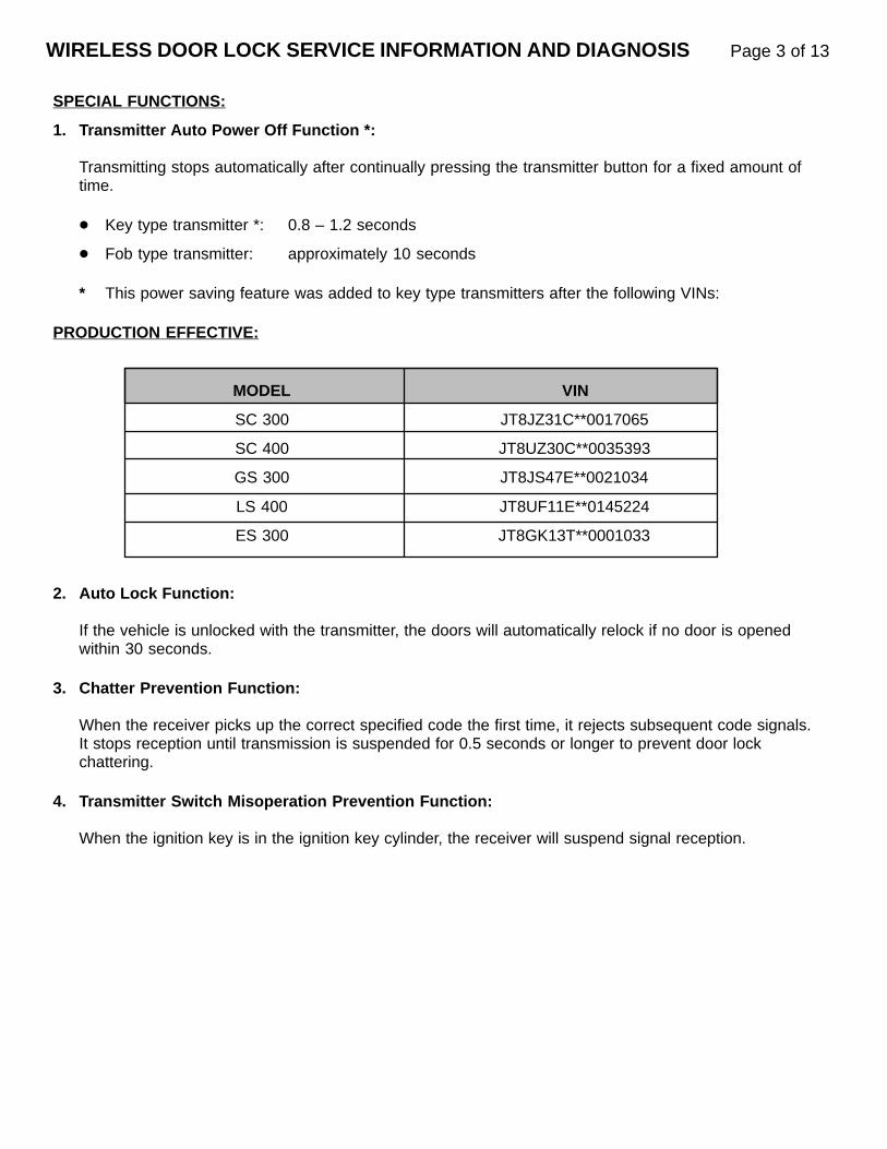
WIRELESS DOOR LOCK SERVICE INFORMATION AND DIAGNOSIS Page 3 of 13
SPECIAL FUNCTIONS:
1. Transmitter Auto Power Off Function *:
Transmitting stops automatically after continually pressing the transmitter button for a fixed amount oftime.
Key type transmitter *: 0.8 – 1.2 seconds
Fob type transmitter: approximately 10 seconds
* This power saving feature was added to key type transmitters after the following VINs:
PRODUCTION EFFECTIVE:
MODEL VIN
SC 300 JT8JZ31C**0017065
SC 400 JT8UZ30C**0035393
GS 300 JT8JS47E**0021034
LS 400 JT8UF11E**0145224
ES 300 JT8GK13T**0001033
2. Auto Lock Function:
If the vehicle is unlocked with the transmitter, the doors will automatically relock if no door is openedwithin 30 seconds.
3. Chatter Prevention Function:
When the receiver picks up the correct specified code the first time, it rejects subsequent code signals.It stops reception until transmission is suspended for 0.5 seconds or longer to prevent door lockchattering.
4. Transmitter Switch Misoperation Prevention Function:
When the ignition key is in the ignition key cylinder, the receiver will suspend signal reception.

WIRELESS DOOR LOCK SERVICE INFORMATION AND DIAGNOSIS Page 4 of 13
WIRELESS DOOR LOCK CONTROL SYSTEM DIAGNOSIS:
IMPORTANT: All wireless diagnosis must start at this point and proceed as directed. Diagnostic information from this point forward assumes that all preceding steps have been properlyperformed. If steps are performed improperly or started beyond this point, an erroneousdiagnosis may be obtained.
Start here by performing the following power door lock control and theft deterrent system checks:
1. Verify that both interior power door lock control switches will lock and unlock all doors.
2. Verify that driver and passenger door key locks will lock and unlock* all doors.
3. Verify that the theft deterrent system will arm when all doors are closed and locked.
* Driver’s door key lock must be cycled twice to unlock all doors.
If any of the above items do not operate normally, refer to either the (Power) Door Lock Control System or TheftDeterrent System section of the repair manual for diagnosis. The wireless feature is an enhancement to thepower door lock control system and is dependent on proper operation of the power door lock control and theftdeterrent systems.
Choose the applicable problem area from the chart shown below and refer to the listed procedure for diagnosis.
Matrix Chart Of Problem Symptoms:
PROBLEM PROCEDURE PAGE NUMBER
Wireless inoperative at all times A 5
Wireless intermittently inoperative B 7
Wireless has reduced operating distance B 7
Wireless inoperative at specific locations C 8

WIRELESS DOOR LOCK SERVICE INFORMATION AND DIAGNOSIS Page 5 of 13
PROCEDURE A – WIRELESS INOPERATIVE AT ALL TIMES:
1. Check battery capacity (See Page 9 – Battery Capacity Check Procedure).
2. Set FM radio to 94.9 MHz* and press the transmitter button while holding transmitter near radioantenna. If noise interference cannot be heard on the radio when the transmitter is depressed, thetransmitter is faulty. This test is only used to identify a faulty transmitter, a positive result does notguarantee transmitter integrity or sufficient battery capacity.
* This test cannot be performed on and does not apply to vehicles equipped with a fob typetransmitter which uses a frequency that does not have a multiple in the FM frequency range.
REMINDER: Transmitters equipped with the Auto Power Off Function quit transmitting 0.8 – 1.2 seconds after depressing the transmitter button (see Page 3).
3. Enter diagnostic mode:
a. Open driver’s door.
b. Lock all doors using the interior power door lock switch.
c. Insert key in ignition once and remove.
d. Cycle the door locks (unlock and lock = 1 cycle) using the interior power door lock switch 10 times as shown below (if door locks are cycled too slow or too fast, diagnostic mode will not be initiated).
4. Door locks should cycle (unlock/lock) one time automatically to confirm that diagnostic mode hasbeen entered. If door locks do not cycle, repeat Step 3.
NOTE: If attempts to enter the diagnostic mode fail repeatedly, faulty vehicle harness wiring or afaulty receiver may be the cause. Refer to Matrix Chart of Problem Symptoms in the WirelessDoor Lock Control System section of the repair manual for diagnosis.
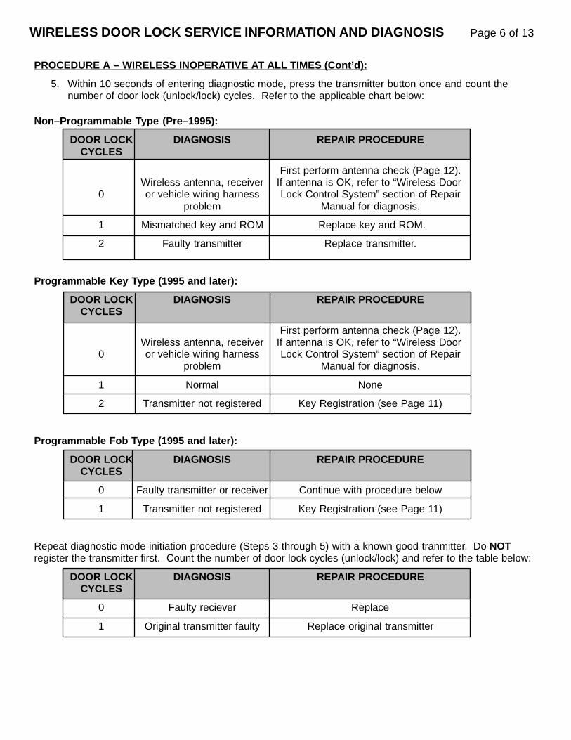
PROCEDURE A – WIRELESS INOPERATIVE AT ALL TIMES (Cont’d):
5. Within 10 seconds of entering diagnostic mode, press the transmitter button once and count thenumber of door lock (unlock/lock) cycles. Refer to the applicable chart below:
Non–Programmable Type (Pre–1995):
DOOR LOCK DIAGNOSIS REPAIR PROCEDURECYCLES
First perform antenna check (Page 12).Wireless antenna, receiver If antenna is OK, refer to “Wireless Door
0 or vehicle wiring harness Lock Control System” section of Repairproblem Manual for diagnosis.
1 Mismatched key and ROM Replace key and ROM.
2 Faulty transmitter Replace transmitter.
Programmable Key Type (1995 and later):
DOOR LOCK DIAGNOSIS REPAIR PROCEDURECYCLES
First perform antenna check (Page 12).Wireless antenna, receiver If antenna is OK, refer to “Wireless Door
0 or vehicle wiring harness Lock Control System” section of Repairproblem Manual for diagnosis.
1 Normal None
2 Transmitter not registered Key Registration (see Page 11)
Programmable Fob Type (1995 and later):
DOOR LOCK DIAGNOSIS REPAIR PROCEDURECYCLES
0 Faulty transmitter or receiver Continue with procedure below
1 Transmitter not registered Key Registration (see Page 11)
Repeat diagnostic mode initiation procedure (Steps 3 through 5) with a known good tranmitter. Do NOT register the transmitter first. Count the number of door lock cycles (unlock/lock) and refer to the table below:
DOOR LOCK DIAGNOSIS REPAIR PROCEDURECYCLES
0 Faulty reciever Replace
1 Original transmitter faulty Replace original transmitter
WIRELESS DOOR LOCK SERVICE INFORMATION AND DIAGNOSIS Page 6 of 13
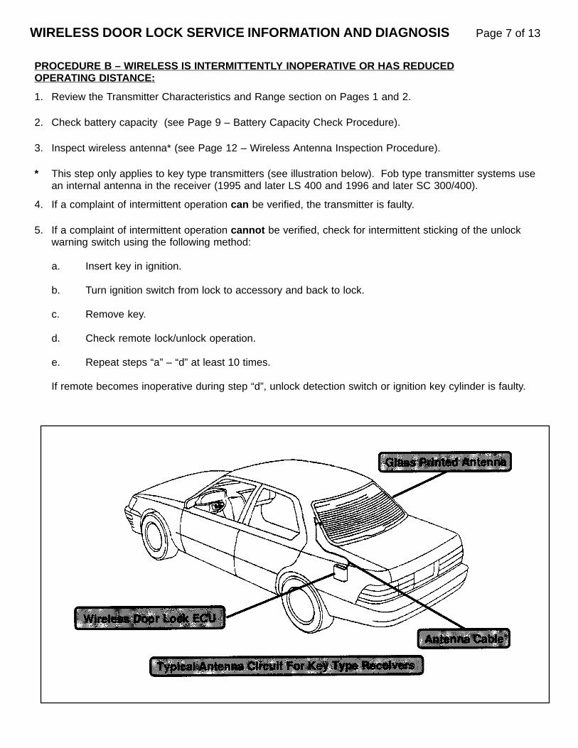
WIRELESS DOOR LOCK SERVICE INFORMATION AND DIAGNOSIS Page 7 of 13
PROCEDURE B – WIRELESS IS INTERMITTENTLY INOPERATIVE OR HAS REDUCEDOPERATING DISTANCE:
1. Review the Transmitter Characteristics and Range section on Pages 1 and 2.
2. Check battery capacity (see Page 9 – Battery Capacity Check Procedure).
3. Inspect wireless antenna* (see Page 12 – Wireless Antenna Inspection Procedure).
* This step only applies to key type transmitters (see illustration below). Fob type transmitter systems usean internal antenna in the receiver (1995 and later LS 400 and 1996 and later SC 300/400).
4. If a complaint of intermittent operation can be verified, the transmitter is faulty.
5. If a complaint of intermittent operation cannot be verified, check for intermittent sticking of the unlockwarning switch using the following method:
a. Insert key in ignition.
b. Turn ignition switch from lock to accessory and back to lock.
c. Remove key.
d. Check remote lock/unlock operation.
e. Repeat steps “a” – “d” at least 10 times.
If remote becomes inoperative during step “d”, unlock detection switch or ignition key cylinder is faulty.
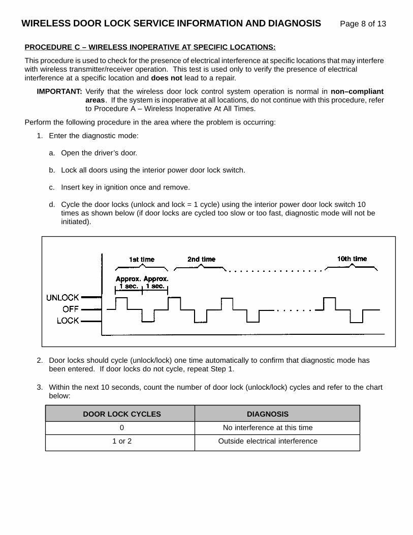
WIRELESS DOOR LOCK SERVICE INFORMATION AND DIAGNOSIS Page 8 of 13
PROCEDURE C – WIRELESS INOPERATIVE AT SPECIFIC LOCATIONS:
This procedure is used to check for the presence of electrical interference at specific locations that may interferewith wireless transmitter/receiver operation. This test is used only to verify the presence of electrical interference at a specific location and does not lead to a repair.
IMPORTANT: Verify that the wireless door lock control system operation is normal in non–compliantareas . If the system is inoperative at all locations, do not continue with this procedure, referto Procedure A – Wireless Inoperative At All Times.
Perform the following procedure in the area where the problem is occurring:
1. Enter the diagnostic mode:
a. Open the driver’s door.
b. Lock all doors using the interior power door lock switch.
c. Insert key in ignition once and remove.
d. Cycle the door locks (unlock and lock = 1 cycle) using the interior power door lock switch 10 times as shown below (if door locks are cycled too slow or too fast, diagnostic mode will not be initiated).
2. Door locks should cycle (unlock/lock) one time automatically to confirm that diagnostic mode hasbeen entered. If door locks do not cycle, repeat Step 1.
3. Within the next 10 seconds, count the number of door lock (unlock/lock) cycles and refer to the chartbelow:
DOOR LOCK CYCLES DIAGNOSIS
0 No interference at this time
1 or 2 Outside electrical interference

WIRELESS DOOR LOCK SERVICE INFORMATION AND DIAGNOSIS Page 9 of 13
BATTERY CAPACITY CHECK PROCEDURE:
The lithium battery used in the transmitter will measure a voltage of 2.5 volts or more until the battery capacityis fully consumed. To accurately determine the remaining battery capacity, a load must be applied.
NOTE: Make all battery checks at room temperature (low temperatures may adversely affectoutput).
1. Key Type Transmitters:Remove screw, pry cover up slightly, and push cover away from portion of the key.
Fob Type Transmitters:Insert a screwdriver and twist to remove cover.
2. Inspect the battery terminals, transmitter case, and cover for corrosion or visible damage. Replacetransmitter if necessary.
3. Depress the transmitter button for 1 second and then release for 1 second. Repeat this process 5times.
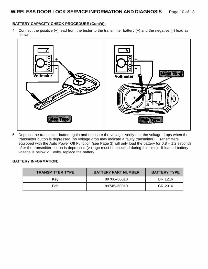
WIRELESS DOOR LOCK SERVICE INFORMATION AND DIAGNOSIS Page 10 of 13
BATTERY CAPACITY CHECK PROCEDURE (Cont’d):
4. Connect the positive (+) lead from the tester to the transmitter battery (+) and the negative (–) lead asshown.
5. Depress the transmitter button again and measure the voltage. Verify that the voltage drops when thetransmitter button is depressed (no voltage drop may indicate a faulty transmitter). Transmittersequipped with the Auto Power Off Function (see Page 3) will only load the battery for 0.8 – 1.2 secondsafter the transmitter button is depressed (voltage must be checked during this time). If loaded batteryvoltage is below 2.1 volts, replace the battery.
BATTERY INFORMATION:
TRANSMITTER TYPE BATTERY PART NUMBER BATTERY TYPE
Key 89706–50010 BR 1216
Fob 89745–50010 CR 2016

WIRELESS DOOR LOCK SERVICE INFORMATION AND DIAGNOSIS Page 11 of 13
KEY REGISTRATION (1995 AND LATER MODELS):
Set initial conditions:
Key out of ignition
Driver’s door open and unlocked
All other doors closed and locked
Registration Procedure:
NOTE: Perform all steps with no more than a five second interval between steps.
1. Insert key into ignition for 1 second and remove.
2. Cycle (lock and unlock = 1 cycle) the driver’s interior power door lock switch 5 times (1 second in each position).
3. Close and reopen driver’s door.
4. Cycle the driver’s interior power door lock switch 5 times (1 second in each position).
5. Insert key into ignition and cycle the ignition on and off:
One time to add a new code.
Two times to add a new code and erase all previously stored codes.
Three times to check how many codes are currently registered.
6. Remove key from ignition. Receiver should respond by cycling the door locks a correspondingnumber of times:
One time to add a new code.
Two times to add a new code and erase all previously stored codes.
One to four times (slowly) to indicate how many codes are registered (end).
NOTE: If no response is given, start over at the beginning of this procedure.
7. Press the transmitter button (any button on fob type transmitters) for 1 second.
NOTE: Receiver should respond by cycling door locks once. If no response is given, start over at thebeginning of this procedure.
8. Close and reopen driver’s door.
9. Press the transmitter button for 1 second. Receiver should respond by cycling door locks:
One time to confirm operation is complete.
Two times to signal that the code is already registered.

WIRELESS DOOR LOCK SERVICE INFORMATION AND DIAGNOSIS Page 12 of 13
WIRELESS ANTENNA INSPECTION PROCEDURE:
If wireless operation is verifiably inoperative, use Procedure A , otherwise use Procedure B .
Procedure A:
Remove antenna cable from receiver. Insert key into receiver antenna port as shown below. Press transmitterbutton several times while monitoring door lock operation.
If door locks are still inoperative, the antenna circuit is not the primary problem.
If door lock operation is consistent:
1. Inspect rear glass for damaged or broken wires and replace glass if necessary.
2. If rear glass is OK, replace wireless antenna cable.
Procedure B:
Perform the following checks:
1. Inspect rear glass for damaged or broken wires and replace glass if necessary.
2. Inspect antenna cable connections at rear glass and at receiver.
3. Physically inspect antenna cable for pinches or breaks and replace cable if necessary.
4. Check continuity through inner coaxial cable wire and replace cable if necessary.

WARRANTY INFORMATION:
OPCODE DESCRIPTION TIME OPN T1 T2
Transmitter replacement includeskey registration or installation of
891101 the ROM in the ECU where 0.3 897XX–50XXX 95 71applicable and all necessary
checks and tests
For VCV10Transmitter replacement includes
EL6002 the ROM in the ECU where 0.2 897XX–50XXX 95 71applicable and all necessary
checks and tests
EL6003 Receiver replacement including all 0.3 5974X–50XXX 95 71necessary checks and tests
830651 Ignition key cylinder R&R including * 84450–XXXXX 72 71all necessary checks and tests
Door key (unlock/lock) switch R&R672101 including all necessary checks and * 69052–XXXXX 95 71
tests
NOTE: Replacement of the transmitter battery is not warrantable as per the Lexus Warranty Policy &Procedures Manual.
* Refer to the specific model in the Lexus Flat Rate Manual for repair time.
WIRELESS DOOR LOCK SERVICE INFORMATION AND DIAGNOSIS Page 13 of 13

TSIBIntroduction The following is a listing of 1997 Lexus paint codes and corresponding refinish formula
codes for 8 (eight) refinish paint companies –– BASF, DuPont, PPG, Sherwin Williams,Sikkens, Spies Hecker, ICI and Standox* (Paint and refinish formula codes are locatedon page 2).
* Standox uses the Lexus color code number as their paint code identification number.
Example: The Standox paint code number for Lexus color code 202 (Black Onyx) is202.
NOTE:The body color code is indicated on the Certification Label which is located in the driver’s door area as shown below.
PAIN
T
March 7, 1997
Title:
1997 PAINT AND REFINISH FORMULACODESModels:
All Models
Page 1 of 4
PA
001–97
Please contact your local paint representative for the actual paint mixingformulas or for additional assistance in color matching.
Please provide a copy of this information to your Lexus Collision Repair Center.

1997 PAINT AND REFINISH FORMULA CODES – PA001–97 March 7, 1997
Paint Codes & COLOR COLOR NAME BASF DUPONT PPG SHERWIN SIKKENS SPIES- ICI
Color Names CODE WILLIAMS HECKER
045 Super White TOY045 H8931 90547 38712 TOY045 16004 NP65
051 Diamond White Pearl TOY051 TOY051
1A0 Platinum Metallic TOY1A0 N9923 4896 49700 TOY1A0 70809 6ED5B
199 Alpine Silver Metallic TOY199 L9990 4900 48976 TOY199 70706 5TX1B
1B1 Champagne Pearl TOY1B1 F2186 5252 53074 TOY1B1 20699 FLT9B
1B2 Antique Sage Pearl TOY1B2 F2201 5324 54757 TOY1B2 73622 HRE5B
202 Black Onyx TOY202 F0220 9300 TOY202 73935 TH21B
3K7 Shadow Rose Quartz TOY3K7 H9650 4615 46620 TOY3K7 99745 PM71B
3L2 Renaissance Red TOY3L2 L9992 4902 48978 TOY3L2 30491 5TX3B
3L3 Ruby Red Pearl TOY3L3 F0294 5042 51162 TOY3L3 30914 6KD3B
3L4 Bordeaux Pearl TOY3L4 F1803 5164 52886 TOY3L4 33135 ARD1B
4M7 Oyster Pearl TOY4M7 K9968 27579 48841 TOY4M7 10655 5MK6B
4M9 Cashmere Beige Metallic TOY4M9 N9924 4903 49702 TOY4M9 20261 6ED6B
4N1 Crystal Quartz Metallic TOY4N1 F1052 5057 51185 TOY4N1 80373 7VS8B
6M1 Dark Emerald Green Prl. TOY6M1 W9542 4595 46589 TOY6M1 99746 PM72B
6N0 Moonstone Pearl TOY6N0 F1053 5049 51187 TOY6N0 61495 7VT1B
6N9 Ebony Teal Pearl TOY6N9 F1054 5050 51189 TOY6N9 61496 7VT2B
6P2 Classic Green Pearl TOY6P2 F1850 5173 52889 TOY6P2 61953 BAA7B
6P3 Deep Jewel Green Pearl TOY6P3 F1805 5166 52887 TOY6P3 61928 ARD3B
6P7 Silver Jade Metallic TOY6P7 F2719 5332 54755 TOY6P7 64197 HRE3B
8L1 Star Sapphire Pearl TOY8L1 F1055 5052 51191 TOY8L1 53765 7VT3B
8L3 Blue Velvet Pearl TOY8L3 F2239 5328 54032 TOY8L3 54676 FRC7B
8L5 Royal Sapphire Pearl TOY8L5 F2728 5329 54485 TOY8L5 55068 HDJ4B
Page 2 of 4
L9246 90822 42872 98125 PF76BL9247 90826 42873 16329 TD86G
1738SW8803MS

COLOR CODE LS 400 SC 400 SC 300 GS 300 ES 300 LX 450
045
051
1A0
199
1B1
1B2 NEW
202
3K7 NEW NEW3L2
3L3
3L4
4M7 NEW4M9
4N1
6M1
6N0
6N9
6P2 NEW NEW6P3
6P7 NEW
8L1
8L3 NEW8L5 NEW NEW
Page 3 of 4
1997 PAINT AND REFINISH FORMULA CODES – PA001–97 March 7, 1997
PaintApplications
& Types
Paint FilmCross
Sections
PAINT TYPE #1
Solid Color – Non Clear Coat
Codes: 202 (Except LX 450)
PAINT TYPE #2
Metallic or Mica Color – Clear Coat
Codes: 1A0, 199, 3K7, 3L3, 3L44M7, 4M9 (Except LX 450),4N1, 6N0, 6P2, 6P3, 6P7, 8L1,8L3, 8L5

1997 PAINT AND REFINISH FORMULA CODES – PA001–97 March 7, 1997
Page 4 of 4
Paint FilmCross
Sections(Continued)
PAINT TYPE #3
MIO Color – Two Clear Coats
Codes: 6N9
PAINT TYPE #4
Pearl Mica Color – One Clear Coat
Codes: 051
PAINT TYPE #5
Solid Color – Tinted Clear Coat
Codes: 3L2
PAINT TYPE #6
Solid Color – Non Clear Coat
Codes: 045, 202 (LX 450 only)
PAINT TYPE #7
Metallic or Mica Color – Clear Coat
Codes: 1B1, 1B2, 4M9 (LX 450 only),6M1

Title 1997 MODEL YEAR PAINT COLORS Page 1 of 3
The following information outlines the single and two–tone painting schemes used on 1997 modelyear Lexus models.
PAINTING METHOD:
Single Color – The cladding and bumpers are painted with the same color.
Two–Tone Color – The claddings and bumpers are painted with a different color from the body color to achieve a two–tone painting scheme.
LS 400 TWO–TONE COLORS:
REF: PAINT
NO: PA003–96
MODEL: ALL MODELS
BODY COLOR CLADDING COLOR SINGLE/TWO–TONE NAME
051 UCA29 Diamond White Pearl/Warm Silver Metallic
199 UCA75 Alpine Silver Metallic/Gray Silver Metallic
202 UCA31 Black Onyx/Dark Gray Metallic
4M9 UCA77 Cashmere Beige Metallic/Beige Metallic
4N1 UCA78 Crystal Quartz Metallic/Dark Taupe Metallic
6N0 UCA76 Moonstone Pearl/Medium Gray Metallic
6N9 UCA31 Ebony Teal Pearl/Dark Gray Metallic
6P3 6N0 Deep Jewel Green Pearl/Moonstone Pearl
6P7 UCAA5 Silver Jade Pearl/Greenish Gray Pearl
8L1 UCA32 Star Sapphire Pearl/Dark Bluish Gray Metallic
DATE: DECEMBER 4, 1996

GS 300 SINGLE AND TWO–TONE COLORS:
ES 300 TWO–TONE COLORS:
ES 300 SPECIAL EDITION COLORS:
1997 MODEL YEAR PAINT COLORS Page 2 of 3
BODY COLOR CLADDING COLOR SINGLE/TWO–TONE NAME
051 UCA29 Diamond White Pearl/Warm Silver Metallic
199 199 Alpine Silver Metallic (One Color)
202 202 Black Onyx (One Color)
3L3 3L3 Ruby Pearl (One Color)
4M9 4M9 Cashmere Beige Metallic (One Color)
6N0 6N0 Moonstone Pearl (One Color)
6N9 UCA93 Ebony Teal Pearl/Warm Gray Mica Metallic
8L1 8L1 Star Sapphire Pearl (One Color)
BODYCOLOR
CLADDINGCOLOR TWO–TONE NAME
051 UCA46 Diamond White Pearl/Light Grayish Beige Metallic
1B2 UCAA3 Antique Sage Pearl/Medium Green Gray Metallic
202 UCA45 Black Onyx/Bluish Gray Metallic
3L3 3K2 Ruby Pearl/Dark Red
4M7 UCAA2 Oyster Pearl/Light Brown Gray Metallic
4M9 UCA46 Cashmere Beige Metallic/Light Grayish Beige Metallic
6P2 UCA45 Classic Green Pearl/Bluish Gray Metallic
8L3 UCA45 Blue Velvet Pearl/Bluish Gray Metallic
BODYCOLOR
CLADDINGCOLOR TWO–TONE NAME
046 UC178 Opal White Pearl/Light Rose Silver Metallic
176 UC196 Silvermist Metallic/Pewter Pearl
202 UC138 Black Onyx/Dark Gray Metallic

1997 MODEL YEAR PAINT COLORS Page 3 of 3
LX 450 TWO–TONE COLORS:
REPAIR PROCEDURE:
Since heat deformation of the cladding occurs more easily than bumpers, repair and refinishing of theseparts is not recommended. If original parts are to be refinished, observe the following precautions duringthe refinish/drying process:
1. To prevent cladding warpage, firmly hold the cladding in place and keep drying temperature below 50C (122F).
2. Since the cladding and bumpers are made of a flexible plastic urethane material, use a 2–part urethane finish paint system with plasticizer for all bumper/cladding repairs.
BODYCOLOR
CLADDINGCOLOR TWO–TONE NAME
045 UCA46 Super White/Light Grayish Beige Metallic
1B1 UCA46 Champagne Pearl/Light Grayish Beige Metallic
202 UCA31 Black Onyx/Dark Gray Metallic
4M9 UCA46 Cashmere Beige Metallic/Light Grayish Beige Metallic
6M1 UCA31 Dark Emerald Pearl/Dark Gray Metallic

TSIBIntroduction Corrections have been made in the repair manuals listed below. A brief Description
of each correction is provided. For further details, refer to the appropriate Correction Page (attached to this TSIB for Dealer Area Office distribution). These pages should be attached in the corresponding publication.
NOTE:When ordering a technical publication (i.e. Repair Manual, Electrical Wiring Diagram) From the MDC, any Correction Page(s) associated with that particular Publication, will be automatically included with your order.
Additional Correction Pages are available through the Dealer Support Material Network (MDC NPM System) via the corresponding part numbers from the following table:
PR
OD
UC
T G
EN
ER
AL IN
FO
RM
ATIO
N
February 28, 1997
Title:
PUBLICATION CORRECTION INFORMATION
Models:
‘95 - ‘97 LS 400, ‘97 GS 300, ‘97 ES 300,‘97 LX 450
Page 1 of 2
PG
001-97
PUBLICATION NUMBER PAGE(S) DESCRIPTION PART NUMBERPartsInformation AUTOMATIC TRANSMISSION-
TROUBLESHOOTING.INSPECTION PROCEDURE-Step 1 was completely revised.Step 2, P 1. Remove transmission.was revised to 1. Remove the oilpan.
`95 LS 400Repair Manual
RM405U1 AT74 00245RM4056012
AUTOMATIC TRANSMISSION-
TROUBLESHOOTING.INSPECTION PROCEDURE-Step 1 was completely revised.Step 2, P 1. Remove transmission.was revised to 1. Remove the oilpan.
`96 LS 400Repair Manual
RM439U1 AT51 00245RM4396012
BRAKE FRONT BRAKE.5. MEASURE DISC RUNOUT (B)Text revised to include . . . grind it on aoncar" brake lathe.`97 LS 400
Repair Manual
RM514U1
BR24
00245RM5146041
RM514U
BR18
BRAKE FRONT BRAKE (Disc Brake)4. MEASURE DISC RUNOUT Text revised to include . . . grind it on a oncar"brake lathe.
`97 GS 300Repair Manual
RM512U BR17
BRAKE FRONT BRAKE.3. MEASURE DISC RUNOUT Textrevised to include . . . grind it on a oncar" brake lathe.
00245RM5126041

PUBLICATION CORRECTION INFORMATION – PG001-97 February 28, 1997
Page 2 of 2
PUBLICATION NUMBER PAGE(S) DESCRIPTION PART NUMBERPartsInformation
BRAKE REAR BRAKE (Disc Brake).REAR BRAKE COMPONENTS INSPECTION AND REPAIR.3. MEASURE DISC RUNOUT Text revised to include . . . grind it on a oncar"brake lathe.
`97 GS 300Repair Manual
RM512U BR20 00245RM5126041
BRAKE ANTILOCK BRAKE SYSTEM.DTC REAR SPEED ROTOR FAULTY Revised to 33, 34.
`97 ES 300Repair Manual
RM511U DI248 00245RM5116048
BRAKE BRAKE BOOSTER ASSEMBLY.BRAKE BOOSTER ASSEMBLY Entirepage has been revised from Brake Master Cylinder Removal and Disassemblyto Brake Booster Assembly OperationalTest and Components.
`97 LX 450Repair Manual
RM515U BR10 00245RM5156055
(Continued)

TSIBIntroduction Based on the Federal Motor Vehicle Safety Standard (FMVSS) 208, the Air Bag
Information label (1) will be hung on the glove box door for vehicles having a passengerside air bag and produced on or after 2/25/97.
NOTE:The air bag caution label (2) affixed voluntarily on the passenger side end of the vehicle dash will be eliminated with this change.
Affected LS 400, GS 300, SC 400, SC 300, ES 300, LX 450 built after February 25, 1997.Vehicles
NOTE:The Air Bag Information label is NOT required on vehicles built prior to 2/25/97.
Parts NEW PART NUMBER PART NAME
Information74599–06010 Label, Driver and Passenger Information
Procedure 1. During PDS, check to insure thatvehicles produced on or after 2/25/97are in compliance with FMVSS 208 byhaving the label hung on the glove boxdoor.
2. If the label is missing or damaged, theappropriate label can be orderedthrough the parts system.
PR
OD
UC
T G
EN
ER
AL IN
FO
RM
ATIO
N
March 21, 1997
Title:
AIR BAG INFORMATION LABEL ON GLOVEBOX DOORModels:
All Models
Page 1 of 1
PG
002–97

TSIBIntroduction Replacement Certification Labels (vinyl label affixed to driver’s door or door post) may be
available from Lexus providing the request meets one of the criteria listed below.
PR
OD
UC
T G
EN
ER
AL IN
FO
RM
ATIO
N
July 18, 1997
Title:
REPLACEMENT CERTIFICATION LABELS
Models:
All Models
Page 1 of 2
PG
003-97
Affected • All Lexus vehicles.Vehicles
Certification 1. The vehicle is in an accident and the label is damaged or is attached to a part that willLabel be replaced during the repair.
Criteria
NOTE:• Processing a new label will be delayed if the old certification label is not
available.• A new label MAY NOT be available if the vehicle is more than five years old and
the old label does not accompany this request.
2. The label is stolen.
Procurement To request a replacement label, complete a copy of the form on the back of this bulletin.Procedure Your dealer parts account will be billed $10.00 for each replacement of a damaged or
stolen label.
NOTE:All replacement labels for damaged and/or stolen vehicles are subject to approvalby the Technical Compliance Department. If you have any specific questions, contact (310)781-3390.
Warranty • No applicable Warranty InformationInformation

Page 2 of 2
NOTE:Original label MUST accompany this application or order will be delayed.

DATE: SEPTEMBER 6, 1996
Title 1997 ES 300 SHORT PIN INSTALLATION DURING PDS Page 1 of 1
To minimize battery discharge during transportation and storage, the Short Pin has been removed at theassembly plant.
REF: PRODUCT GENERALINFORMATION
NO: PG004–96
MODEL: ES 300
INSTALLATION PROCEDURE:
The Short Pin is stored in the Engine Room J/B No.2 in the engine compartment as shown in Figure A.
NOTE: Removal of the Short Pin cuts offthe power source to the Dome Fuseand ECU–B fuse.
During PDS (Pre-Delivery Service) install the ShortPin in the correct position as shown in Figures B andC.
CAUTION:The Short Pin is not a fuse. Pleaseinstall only in the position shown inFigure C.
NOTE: If the vehicle is stored at thedealership for a long period of timeafter PDS, disconnect the negativebattery terminal to prevent batterydischarge. Refer to TSIB EL002-96for battery maintenance information.
Fig. A
Fig. B
Fig. C
Engine Room J/B No. 2
Engine Room J/B No. 2

TSIBIntroduction Replacement VIN plates (metal plate riveted to dashboard) may be available from Lexus
providing the request meets one of the criteria listed below.
PR
OD
UC
T G
EN
ER
AL IN
FO
RM
ATIO
N
July 18, 1997
Title:
REPLACEMENT VIN PLATES
Models:
All Models
Page 1 of 2
PG
004-97
Affected • All Lexus vehicles.Vehicles
Replacement • The vehicle is in an accident and the plate is damaged.VIN Plate
Criteria NOTE:The plate to be replaced MUST accompany the request.
NOTE:If a plate is stolen, be sure to contact the State Police or the Department of MotorVehicles. In most cases the state will issue a unique number so that the originalnumber can be included on stolen vehicle listings. If this is the case, a replacementVIN plate is NOT available from Lexus. However, the original VIN, NOT the state-issued VIN, must be used on all warranty claims.
Procurement To request a replacement plate, complete a copy of the form on the back of this page.Procedure Note that damaged VIN plates must accompany the request form. Your dealer parts
account will be billed $10.00 for each replacement of a damaged plate.
NOTE:All replacement plates for damaged and/or stolen vehicles are subject to approvalby the Technical Compliance Department. If you have any specific questions,contact (310)781-3390.
Warranty • No applicable Warranty Information.Information
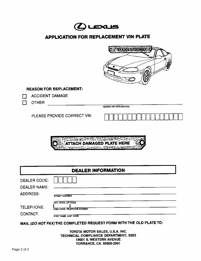
Page 2 of 2

DATE: SEPTEMBER 6, 1996
Title ‘97 ES 300 FRONT SUSPENSION SPACERS REMOVAL DURING PDS Page 1 of 2
To prevent damage to the underside of the front bumper during vehicle transport, suspension spacershave been installed on the front coil springs for the 1997 ES 300.
Please use the following procedures to remove the suspension spacers during PDS (Pre–Delivery Service).
SUSPENSION SPACERS REMOVAL PROCEDURE:
1. During the Under Vehicle (On Hoist) checks portion of the Pre-Delivery Service, raise the vehicle toextend the suspension.
2. Firmly grasp the lower part of the spring spacer with your hand.
REF: PRODUCT GENERALINFORMATION
NO: PG005–96
MODEL: ES 300

‘97 ES 300 FRONT SUSPENSION SPACERS REMOVAL DURING PDS Page 2 of 2
SUSPENSION SPACERS REMOVAL PROCEDURE ( Cont’d) :
3. Pull the spring spacer toward you and push it upward.
4. Pull the ring spacer downward to remove.
5. Repeat steps 2 through 4 above on the other side to complete removal of the spring spacers.

DATE: SEPTEMBER 6, 1996
Title 1997 ES 300 LICENSE PLATE INSTALLATION DURING PDS Page 1 of 2
During shipment the 1997 ES 300 front license plate mounting bracket and two attaching screws areplaced in a plastic bag in the luggage compartment. Install the mounting bracket cover on the front bumper during PDS (Pre-Delivery Service) according to the following procedures.
REF: PRODUCT GENERAL INFORMATION
NO: PG006–96
MODEL: ES 300
FRONT LICENSE PLATE INSTALLATION:
1. Align the holes marked “A” on the mountingbracket with the dimples on the front bumpercover. Mark the location of the holes marked“B” on the front bumper cover.
NOTE: Holes marked “A” are used forinstallation of the mounting bracket tothe bumper cover. Holes marked “B”are used for installation of the licenseplate to the mounting bracket.
2. Drill 2 relief holes, 11 mm (7/16 in.) in diameter,through the bumper cover at the marks madeat holes marked “B”. The relief holes provideclearance to prevent the license plate retainingscrew from contacting the bumper cover.
NOTE: Do NOT drill at the dimples on the frontbumper cover.

1997 ES 300 LICENSE PLATE INSTALLATION DURING PDS Page 2 of 2
FRONT LICENSE PLATE INSTALLATION:
3. Install the mounting bracket to the front of the bumpercover (at holes marked “A”) using the 2 tapping screwssupplied with the bracket.
4. Install the license plate to its bracket using 2 tappingscrews with the following dimensions:
Nominal length (L): < 25.0 mm (9.8 in.)
Diameter: 6.0 mm (0.24 in.)
Pitch: 1.0 mm (0.04 in.)

DATE: AUGUST 20, 1996
Title VERSION 3.1 DIAGNOSTIC TOOL SET SOFTWARE COMMUNICATION PROBLEM WITH 1997 ES 300
Due to a change in communication standard for the 1997 ES 300, the Version 3.1 Diagnostic Tool SetSoftware will display the error message below when the technician attempts to use the ALL DATA list orthe ACTIVE TEST functions in ENHANCED OBD II.
This problem will be corrected with the release of 1997 Model Year software in November. Until then, thereare two alternatives for diagnosing the ES 300 with the current Version 3.1 software:
1. ENHANCED OBD II
USER DATA list (less than 50 data lines)
Specialized data list from SELECT DATA menu (MISFIRE, O2 SENSOR, EGR, etc.)
2. CARB ORB II
All CARB OBD II function work normally.
REF: SPECIAL SERVICETOOLS
NO: SS001–96
MODEL: ES 300
NO RESPONSEFROM VEHICLE.
CHECK CONNECTIONTO VEHICLE.
ORTHIS TEST IS NOTSUPPORTED FOR
THIS VEHICLE.

TSIBIntroduction When inspecting or making brake booster push rod adjustments with SST 09737–00010,
it is necessary to assure proper tool configuration prior to use. The SST has a reversiblecenter plunger that allows it to function on a wide range of Lexus vehicles. Prior to using,verify that it is configured correctly for the application by checking the master cylinderouter diameter at the point illustrated below. The dimensions for the SST, Part Number09737–00010, are also shown in the illustrations below.
SP
EC
IAL S
ER
VIC
E TO
OLS
September 26, 1997
Title:
BRAKE BOOSTER PUSH ROD GAUGE (SST)Models:
All Models
Page 1 of 1
SS
001–97
Parts PART NUMBER PART NAME
Information09737–00010 Brake Booster Push Rod Gauge (SST)
Warranty OPCODE DESCRIPTION TIME OPN T1 T2
InformationN/A Not applicable to warranty – – – –

ENGINE SUPPORT BAR IMPROVEMENTS Page 1 of 1
BOLT BOLT
A new engine support bar, P/N 00002–01724, has been released by OTC. This new tripod designengine support bar, which is designed to support engine weight while transmission service is beingperformed, supersedes the current bipod engine support bar, P/N 00002–01722.
For dealers who currently own the 00002–01722 engine support bar, OTC has developed an upgrade kit, P/N 00002–01724–U which includes all necessary components and hardware to convertit to the new tripod design. To avoid the potential for personal injury or property damage, donot use the existing engine support bar without the new upgrade kit.
00002–01724 00002–01724–U
TRIPOD ENGINE SUPPORT BAR KIT TRIPOD UPGRADE KIT
DEALER PRICING IS AS FOLLOWS:
AVAILABLE SST’S
TOOL NUMBER TOOL NAME PRICE
00002–01724 Tripod Engine Support Bar Kit $165.35
00002–01724–U Tripod Upgrade Kit $ 77.25
For more information and to order these Special Service Tools, please call OTC at 800–933–8335.
SPECIAL SERVICE TOOLSSS95–002OCTOBER 27, 1995ALL MODELS

DATE: NOVEMBER 29, 1996
KNOCKING NOISE UNDER FLOOR IN REAR Page 1 of 2
REF: SUSPENSION
NO: SU005–96
MODEL:
To eliminate a knocking noise heard under the floor in the rear, caused by interference between the rearfloor side member and the front end of the rear strut rod, the clearance between the side member andthe rear strut rod has been increased.
ES 300
Floor Side MemberRear Strut Rod
“A” Section“A” Section “A” Section
Floor Side Member
Strut Rod
Strut Rod Bush
B – B’ Cross Section
Floor Panel Floor Panel
Previous New
PRODUCTION EFFECTIVE:
Starting VIN: JT8BF22G–V0002236

KNOCKING NOISE UNDER FLOOR IN REAR Page 2 of 2
FIELD FIX PROCEDURE:
Note : Make sure that the end of thebrass bar is smooth and rounded toprevent damage to the vehiclefloor.
3. Using a brass bar and a hammer, dent the cross hatched area of the rear floor side member by about 1–2 mm in order to increasethe clearance between the front end of the rear strut rod and the side member. There may be a shinny area where the strut rod hasmade metal–to–metal contact.
4. Apply a rust preventive sealer to the area thathas been modified.
1. Raise vehicle on hoist.
a. Remove the bolt and disconnect the parking brake cable.
WARRANTY INFORMATION:
2. Remove rear strut rod.
b. Remove the two bolts and nuts.
c.. Remove the strut rod.
5. Reinstall the rear strut rod with the two bolts and nuts.
Note : Do not torque the bolts until thevehicle is lowered and thesuspension has been stabilized.
6. Reinstall the parking cable with the bolt. Torque: 5.4 N m (55 Kg cm, 48 in lb)
7. Lower the vehicle, stabilize the suspension atride height, then torque the rear strut rod bolts.
Torque: 113 N m (1,150 Kg cm, 83 ft lb)
TIME OPN T1 T2DESCRIPTIONOPCODE
SU6010 Knocking noise under floor in rear 48780–330100.5 91 57
Rear Floor Side Member
Applicable Warranty Coverage: 4 years/50,000 miles Basic Warranty Coverage.

TSIBIntroduction To prevent overheating of the transmission when towing a weight of more than 1,000
pounds, a transmission oil cooler should be installed. The transmission oil cooler andrequired hardware for installation are available through normal parts supply.
Towing Up to 2,000 pounds (with transmission cooler installed).Capacity
TR
AN
SM
ISS
ION
& C
LUT
CH
October 17, 1997
Title:
TRANSMISSION OIL COOLER INSTALLATIONModels:
’97 ES 300 WITH A541E ATM
Page 1 of 6
TC
003–97
Affected 1997 ES 300s with A541E Automatic Transmissions.Vehicles
Parts PART NUMBER PART NAME QTY
Information32910–33040 Oil Cooler Assembly 1
32907–33050 Oil Cooler Tube No. 2 1
32907–33090 Oil Cooler Tube No. 1 1
90445–17101 180 mm (7.09”) Oil Cooler Hose 1
90445–17069 190 mm (7.48”) Oil Cooler Hose 1
90445–17139 130 mm (5.12”) Oil Cooler Hose 3
90445–17151 140 mm (5.51”) Oil Cooler Hose 1
90119–06518 Bolt 3
91611–60816 Bolt 2
90467–16013 Hose Clamp with installation clips 12
90179–06058 Nut 1
Warranty OPCODE DESCRIPTION TIME OPN T1 T2
InformationN/A No applicable warranty information – – – –
Fig. 1

TRANSMISSION OIL COOLER INSTALLATION – TC003–97 October 17, 1997
Procedure 1. Parts removal in preparation for coolerinstallation:
A. Remove the 9 bolts, 2 screws andthe center engine under cover.
B. Remove the engine coolanttemperature switch connector andthe wire clamp.
C. Remove battery and tray.
D. Disconnect the cooling fanconnector.
E. Disconnect the No.1 engine coolanttemperature switch wire connector.
F. Remove the 2 bolts and then thecooling fan.
Page 2 of 6
Fig. 2
Fig. 3
Fig. 4

Page 3 of 6
TRANSMISSION OIL COOLER INSTALLATION – TC003–97 October 17, 1997
Procedure 2. Cooler Installation:(Continued)
A. Install the 140 mm (5.51”) hose tothe oil cooler tube No. 1 as shown.
NOTE:Install the hose clamp with the hoseclamp clip at the position shown, and use pliers to pull off the clip in the direction indicated by the arrow.
B. Install the tube bracket onto the leftside of the front suspensionmember with the 2 bolts as shown.
Torque: 62 in lbf(7 Nm/71 kgf cm)
C. Install the 130 mm (5.12”) hosesand the 180 mm (7.09”) hose to theoil cooler tube No. 2 as shown.
NOTE:Install the hose clamps with the hoseclamp clips at the positions shown, and use pliers to pull off the clips in the direction indicated by the arrows.
Fig. 5
Fig. 6
Fig. 7

TRANSMISSION OIL COOLER INSTALLATION – TC003–97 October 17, 1997
Procedure D. Remove the lower side clip of the(Continued) radiator side LH deflector.
E. Install the tube bracket with the bolton the side member.
Torque: 62 in lbf(7 Nm/71 kgf cm)
F. Reinstall the lower side clip of theradiator LH deflector.
G. Connect the hoses from the oilcooler tube No.2 to the oil coolertube No.1.
NOTE:Install the hose clamps with the hoseclamp clips at the positions shown, and use pliers to pull off the clips in the direction indicated by the arrows.
H. Disconnect the hose from the oilcooler pipe of the radiator LH side.
NOTE:Place a container below vehicle to catch any leaking ATF. Remove the other end of the hose from transaxle and discard.
I. Connect the hose from oil coolertube No. 1 to the oil cooler pipe ofthe radiator LH side.
NOTE:Install the hose clamp with the hoseclamp clip at the position shown, and use pliers to pull off the clip in the direction indicated by the arrow.
Page 4 of 6
Fig. 8
Fig. 9
Fig. 10

Page 5 of 6
TRANSMISSION OIL COOLER INSTALLATION – TC003–97 October 17, 1997
Procedure J. Install the 190 mm (7.48”) hose(Continued) between the oil cooler tube No.1
and transaxle oil cooler tube.
NOTE:Install the hose clamps with the hoseclamp clips at the positions shown, and use pliers to pull off the clips in the direction indicated by the arrows.
K. Install the oil cooler onto the centerbrace and front cross memberusing the two bolts and nut asillustrated in figure 12.
Torque: 65.5 in lbf(7.4 Nm/75.5 kgf cm)
L. Connect the hoses to the pipes
.
NOTE:Install the hose clamps with the hoseclamp clips at the positions shown, and use pliers to pull off the clips in the direction indicated by the arrows.
Fig. 11
Fig. 12
Fig. 13

TRANSMISSION OIL COOLER INSTALLATION – TC003–97 October 17, 1997
Procedure 3. Final Assembly:(Continued)
A. Reconnect the coolant temperatureswitch connector and wire clamp asillustrated in figure 14.
B. Install the cooling fan with 2 bolts.
C. Reconnect the cooling fanconnector and the No. 1 enginetemperature switch wire connectoras shown in figure 15.
D. Reinstall the battery and tray.
E. Start the engine.
F. With the engine at idle and thebrake pedal depressed, shift theselector into all positions from “P” to“L”, and return to “P” position.
G. Check for leaks from the hosejoints.
H. Add new fluid type ATF DII orDEXRONIII (DEXRONII).
NOTE:Additional capacity with cooler will be0.38 US quarts (0.36 liters).
I. Shift the selector into all positionsfrom “P” to “L”, and return to “P”.
J. Check fluid level with engine idlingat normal operating temperature of158 to 176F (70 to 80C) and addmore fluid if required.
CAUTION:Do not overfill.
K. Shut off the engine and reinstall thecenter engine under cover with 9bolts and 2 screws as shown infigure 18.
Page 6 of 6
Fig. 14
Fig. 15
Fig. 16
Fig. 17
Fig. 18

TSIBIntroduction The following production changes have occurred on the A541E transaxle:
1. The oil pan and dipstick have been redesigned for increased oil capacity.
2. The C1 clutch has been changed for improved durability.
Transmission A/T MODEL A/T SERIAL NO.
ProductionChange A541E E0619902–
Information
Parts OLD PART NUMBER NEW PART NUMBER PART NAME QTY
Information30500–33210 30500–33211 Transaxle Assembly, Automatic 1
35106–33010 35106–33020 Pan Sub–assembly, Transaxle Oil *2 1
35103–33120 35103–33160 Gauge Sub–assembly, Transaxle Oil Level *1 1
35701–33030 35701–33050 Shaft Sub–assembly, Input 1
35633–33010 35633–33100 Disc, C1 Clutch 5
35634–3301035634–33020
04352–33050 04352–33051 Overhaul Kit, Automatic Transmission 1
*1 Not interchangeable with previous parts. *2 When using the new oil pan on the old transmission it is necessary to also use the new dip stick. *3 Quantity: 35634–33010 = 4, 35634–33020 = 1 has been changed to 35634–33060 = 5
Warranty OPCODE DESCRIPTION TIME OPN T1 T2
InformationN/A Not Applicable to Warranty – – – –
Details of 1. Transaxle Oil PanProduction
Change A. The Oil Pan depth has beenincreased as indicated bydimensions A and B (illustrationand table).
OLD DIMENSION NEW DIMENSION
A 31.9 mm (1.256”) 34.9 mm (1.374”)
B 15.0 mm (0.591”) 18.0mm (0.709”)
TR
AN
SM
ISS
ION
& C
LUT
CH
October 24, 1997
Title:
OIL PAN, DIP STICK & C1 CLUTCH ON A541EModels:
’97 ES 300
Page 1 of 2
TC
004–97
35634–33060 Plate, C1 Clutch *1 *3 5

OIL PAN, DIP STICK & C1 CLUTCH ON A541E – TC004–97 October 24, 1997
Details of B. With the oil pan change, the oil levelProduction gauge (dip stick) has been revised.
Change(Continued)
OLD DIMENSION NEW DIMENSION
C 62 mm (2.44”)
D 41.5 mm (1.634”) 50.0 mm (1.969”)
E 34.5 mm (1.358”) 42.0 mm (1.654”)
F 10.0 mm (0.394”) 9.0 mm (0.354”)
2. Forward Multiple Disc Clutch Assembly
A. C1 clutch plate thickness has beenincreased to 2.0 mm (0.078”).
OLD DIMENSION NEW DIMENSION
G 1.4 mm (0.055”)
H 1.6 mm (0.063”)
B. Input Shaft Sub–Assembly changedto accommodate thicker C1 clutchplates.
OLD DIMENSION NEW DIMENSION
I 31.7 mm (1.248”) 33.9 mm (1.335”)
C. C1 Clutch Disc material has been changed. Identifying marks can befound on the facing.
PREVIOUS CURRENT
J AD505 AD506
Page 2 of 2
2.0 mm (0.078")

Lexus Supports ASE Certification Page 1 of 1
Title:
MOON ROOF WIND THROB NOISEModels:
’97 & ’98 ES 300Technical Service
Information BulletinJanuary 23, 1998
NV
001–98
To eliminate wind throb on 1997 and 1998 ES 300 vehicles when the moon roof is fullyopened, the roof wind deflector has been raised 3 mm as shown.
Roof Wind Deflector Panel
New Height Roof Wind Deflector PanelRoof Panel
3 mm
Current Height
1997 & 1998 ES 300s starting with VINs:JT8BF28G3W0102176 (TMC – Plant Code “0” – 11th digit)JT8BF28GXW5029522 (TMK – Plant Code “5” – 11th digit)
PREVIOUS PART NUMBER CURRENT PART NUMBER PART NAME
63209–33030 63209–22040 Roof Wind Deflector Panel Sub–Assembly
OP CODE DESCRIPTION TIME OPN T1 T2
614121 R&R Roof Panel Subassembly 0.2 63209–33030 59 14
Applicable Warranty:This repair is covered under the Lexus Basic Warranty. This warranty is in effect for48 months or 50,000 miles, whichever occurs first, from the vehicle’s in–service date.
Replace Roof Wind Deflector Panel subassembly with the new part.
NV
H
Introduction
ProductionChange
Information
PartsInformation
WarrantyInformation
Field FixProcedure

Lexus Supports ASE Certification Page 1 of 2
Title:
IRON PARTICLE RUST
CONTAMINATION REPAIRModels:
’94 – Current
Technical ServiceInformation Bulletin
January 12, 2005
PA
001-05
The purpose of this bulletin is to provide information regarding the proper procedures toclean vehicles that may have been subjected to contamination by airborne iron particlessuch as rail dust.
1994 – Current model year Lexus vehicles.
TOOLS & MATERIALS QUANTITY
Auto Magic Special Cleaner Concentrate #713* 1
Rubber Gloves, Aprons, Boots
Eye ProtectionAs Needed
Sponges or Wash MittsAs Needed
Pail or Bucket
* Contact the main office of Auto Wax Company Inc. (1–800–826–0828 or www.automagic.biz) to find alocal source for Auto Magic Special Cleaner Concentrate.
During rail transportation or extended storage near industrial areas, vehicles mayoccasionally be subjected to contamination by airborne iron particles shed from railroadtracks, train wheels, exposure to heavy machinery facilities, grinding, welding, etc.
This type of contamination can be identified by the presence of small red or brownparticles on the paint surface. These particles are often difficult to see on dark colorpaints, but can be easily felt when brushing a hand across horizontal body surfaces suchas hood, roof, or deck lid.
CAUTION:Because of the abrasiveness of these small iron particles, polishing or buffingprocedures should not be attempted to repair the paint surface of an affected vehicle.This will result in further paint damage and detract from vehicle appearance.
Washing the affected paint surfaces with Auto Magic Special Cleaner Concentrate isthe recommended method to dislodge embedded iron particles and remove thesurrounding rust stains. The correct usage of Auto Magic Special CleanerConcentrate is described in this bulletin.
OP CODE DESCRIPTION TIME OFP T1 T2
N/A Not Applicable to Warranty – – – –
PA
INT
Introduction
ApplicableVehicles
RequiredTools &
Materials
Condition
Inspection
Repair
WarrantyInformation

IRON PARTICLE RUST CONTAMINATION REPAIR – PA001-05 January 12, 2005
Page 2 of 2
WARNING:Auto Magic Special Cleaner Concentrate is a corrosive material. Appropriatepersonal protection equipment must be worn to protect persons performing thecontamination removal procedure. Please refer to the precautions on the product priorto use.
CAUTION:Consult local or state regulations regarding the handling, use, and disposal of AutoMagic Special Cleaner Concentrate prior to use.
Under no circumstances should contamination removal be performed in directsunlight or contamination removal solution be allowed to dry on vehicle surfaces, asstaining of plastic, rubber, or painted parts may result.
1. Move vehicle out of direct sunlight. Initially rinse with cool water then wash with liquidcar wash detergent. Rinse again thoroughly with fresh water.
2. Dilute the mixture to a 1:8 ratio for painted surfaces. Use the recommended dilutionratio when applying to any other surface. Apply the diluted cleaner concentrate sothat it evenly covers the affected area. Use an appropriate mitt or sponge to agitatethe surface.
3. Thoroughly rinse vehicle with fresh water.
4. Inspect vehicle carefully both visually and by feel to determine if all iron particles have been removed. Repeat the wash several times if necessary to achieve complete removal.
5. Dry vehicle with a soft terry cloth towel and apply a non–abrasive, non–silicone glazeto obtain a high–gloss finish.
GeneralPrecautions
RepairProcedure

Lexus Supports ASE Certification Page 1 of 4
Title:
CA/50 STATE CERTIFIED EMISSION
CONTROL UNDERHOOD LABEL
ORDERINGModels:
All Models
Technical ServiceInformation Bulletin
April 7, 2000
PG
001–00
It is no longer necessary to fax the CA/50 State Emission Control Label Order Formto TMS. California (CA) and 50 State Certified underhood emission control labels(emission labels) may now be obtained through your dealership Parts Departmentutilizing standard replacement parts ordering procedures via the TDN. Follow theguidelines outlined in this TSB to ensure proper label application.
All model year Lexus Vehicles.We have included a table showing 1995 – 2000 U.S. model numbers and theirexhaust emissions certifications. Please continue to consult the Electronic PartsCatalog (EPC) or the parts microfiche for emission label parts numbers.
NOTE:Although the California Smog Impact Fee has been discontinued, dealers are stillrequired by regulation to verify the correct emission label is installed on the correctvehicle.
REGULATIONS:The United States Clean Air Act, Title II, Sections 202, 203, 205, and 207 mandates thatthe emission control label must correctly match the emissions equipment on thevehicle. Any person violating this requirement is subject to applicable State penaltiesand a Federal civil penalty of no more than $25,000 for each instance.
Personnel at franchised dealerships are authorized to affix such labels to vehicles andare, therefore, subject to this regulation and the attendant penalties.
Do not sell the labels over the counter. Always install the label on the vehicle.
Never install a California and/or 50 State Label on a vehicle that is not aCalifornia/50 State Emission Certified Vehicle.
Do not install Federal Emission labels on vehicles that are not Federal EmissionsCertified.
OP CODE DESCRIPTION TIME OPN T1 T2
N/A Not Applicable to Warranty – – – –
PR
OD
UC
T G
EN
ER
AL IN
FO
RM
AT
ION
Introduction
ApplicableVehicles
WarrantyInformation

CA/50 STATE CERTIFIED EMISSION CONTROL UNDERHOOD LABEL ORDERING – PG001–00 April 7, 2000
Page 2 of 4
To ensure that the emission control labels are affixed to the correct vehicle, it isnecessary to follow these procedures:
1. Record the Vehicle Identification Number (VIN) from the vehicle requiring areplacement label.
2. Refer to the Vehicle Detail screen in the Lexus Service Inquiry system to determinethe correct 4–digit U.S. model number for the VIN in question.
3. Determine the vehicle’s emission certification using the U.S. model number and theattached tables.
4. Once the emissions equipment information is verified, obtain the part numberinformation by consulting the EPC/microfiche.
5. Order the label through your Parts Department, using normal parts orderingprocedures via the TDN.
6. When the part arrives, verify that the emission label matches the emissionsequipment on the vehicle. This will ensure the correct label is affixed to the vehicle.
Year ModelCA Emission
Model No.50 States Emission
Model No.Federal Emission
Model No.
ES 300 9010 9000
SC 300 9210, 9211 9200, 9201
1995 SC 400 9230 N/A 9220
GS 300 9310 9300
LS 400 9110 9100
LabelOrdering
Procedure
1995 MYEmission
ControlLabels

CA/50 STATE CERTIFIED EMISSION CONTROL UNDERHOOD LABEL ORDERING – PG001–00 April 7, 2000
Page 3 of 4
Year ModelCA Emission
Model No.50 States Emission
Model No.Federal Emission
Model No.
ES 300 9010 9000
SC 300 9210, 9211 9200, 9201
1996SC 400 9230
N/A9220
1996GS 300 9310
N/A9300
LS 400 9110 9100
LX 450 9610 9600
Year ModelCA Emission
Model No.50 States Emission
Model No.Federal Emission
Model No.
ES 300 9010 9000
SC 300 9210, 9211 9200, 9201
1997SC 400 9230
N/A9220
1997GS 300 9310
N/A9300
LS 400 9110 9100
LX 450 9610 9600
Year ModelCA Emission
Model No.50 States Emission
Model No.Federal Emission
Model No.
ES 300 9010 9000
SC 300 9210 9200SC 300 9210 9200
SC 400 9230 9220
1998 GS 300 9310 N/A 9300
GS 400 9330 9320
LS 400 9110 9100
LX 470 9630 9620
1996 MYEmission
ControlLabels
1997 MYEmission
ControlLabels
1998 MYEmission
ControlLabels

CA/50 STATE CERTIFIED EMISSION CONTROL UNDERHOOD LABEL ORDERING – PG001–00 April 7, 2000
Page 4 of 4
Year ModelCA Emission
Model No.50 States Emission
Model No.Federal Emission
Model No.
ES 300 9000, 9010
SC 300 9200, 9210
SC 400N/A
9220, 9230N/A
1999GS 300
N/A9300, 9310
N/A
1999GS 400 9320, 9330
LS 400 9100, 9110
RX 300 9410, 9414 9420, 9424 9400, 9404
LX 470 N/A 9620, 9630 N/A
Year ModelCA Emission
Model No.50 States Emission
Model No.Federal Emission
Model No.
ES 300 9000
SC 300 9200
SC 400 9220
2000GS 300
N/A9300
N/A2000GS 400
N/A9320
N/A
LS 400 9100
RX 300 9420, 9424
LX 470 9620
1999 MYEmission
ControlLabels
2000 MYEmission
ControlLabels

Lexus Supports ASE Certification Page 1 of 1
Title:
VOLUME 4 INFORMATIONModels:
All ModelsTechnical Service
Information BulletinJanuary 1, 1999
PG
001–99
Lexus Technical Service Information Bulletins (TSIBs) continue to be one of the mostcurrent sources of technical information available. To ensure complete access to thisreference source, use the following steps:
Volume Four will begin with 1999 Technical Service Information Bulletins.
Place this bulletin along with all 1999 TSIBs into the new binders received with thisbulletin.
Label this new binder “Volume Four“ using the labels provided with the binder.
Additional copies of 1994 through 1999 TSIBs are available to all Lexus Dealershipsthrough the Non–Parts System (MDC NPM System) by using the following PartNumber designation:
00216 EG 001 99
TSB Part Number PrefixTSB Chapter Code
Chapter Code Sequence NumberYear
––
MATERIAL DESCRIPTION PART NUMBER
1999 TSIB Binder complete with all bulletins issued to date VOL4
New TSIB Binder and tabs only 00216–00001
PR
OD
UC
T G
EN
ER
AL IN
FO
RM
AT
ION
Introduction
Related TSIBPart Numbers
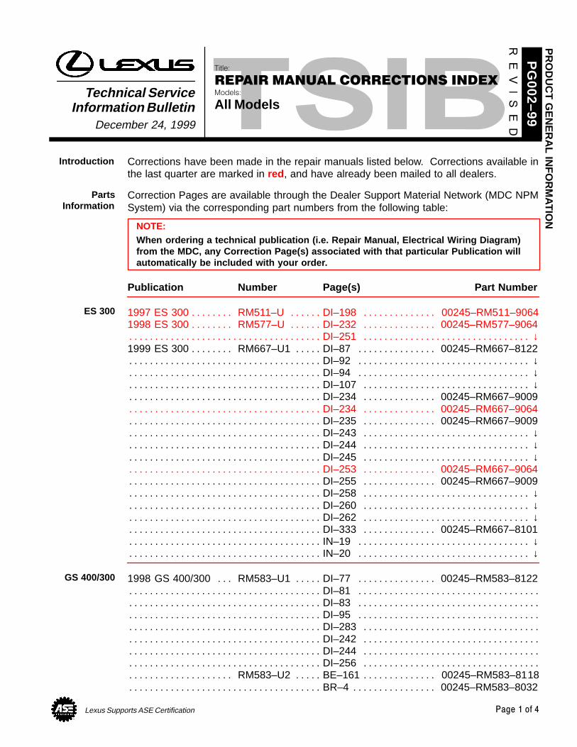
Lexus Supports ASE Certification Page 1 of 4
Title:
REPAIR MANUAL CORRECTIONS INDEXModels:
All ModelsTechnical Service
Information BulletinDecember 24, 1999
PG
002–99
Corrections have been made in the repair manuals listed below. Corrections available inthe last quarter are marked in red , and have already been mailed to all dealers.
Correction Pages are available through the Dealer Support Material Network (MDC NPMSystem) via the corresponding part numbers from the following table:
NOTE:When ordering a technical publication (i.e. Repair Manual, Electrical Wiring Diagram)from the MDC, any Correction Page(s) associated with that particular Publication willautomatically be included with your order.
Publication Number Page(s) Part Number
1997 ES 300 RM511–U DI–198 00245–RM511–9064. . . . . . . . . . . . . . . . . . . . . . . . . . . . 1998 ES 300 RM577–U DI–232 00245–RM577–9064. . . . . . . . . . . . . . . . . . . . . . . . . . . .
DI–251 ↓. . . . . . . . . . . . . . . . . . . . . . . . . . . . . . . . . . . . . . . . . . . . . . . . . . . . . . . . . . . . . . . . . . . . . 1999 ES 300 RM667–U1 DI–87 00245–RM667–8122. . . . . . . . . . . . . . . . . . . . . . . . . . . .
DI–92 ↓. . . . . . . . . . . . . . . . . . . . . . . . . . . . . . . . . . . . . . . . . . . . . . . . . . . . . . . . . . . . . . . . . . . . . . DI–94 ↓. . . . . . . . . . . . . . . . . . . . . . . . . . . . . . . . . . . . . . . . . . . . . . . . . . . . . . . . . . . . . . . . . . . . . . DI–107 ↓. . . . . . . . . . . . . . . . . . . . . . . . . . . . . . . . . . . . . . . . . . . . . . . . . . . . . . . . . . . . . . . . . . . . . DI–234 00245–RM667–9009. . . . . . . . . . . . . . . . . . . . . . . . . . . . . . . . . . . . . . . . . . . . . . . . . . . DI–234 00245–RM667–9064. . . . . . . . . . . . . . . . . . . . . . . . . . . . . . . . . . . . . . . . . . . . . . . . . . . DI–235 00245–RM667–9009. . . . . . . . . . . . . . . . . . . . . . . . . . . . . . . . . . . . . . . . . . . . . . . . . . . DI–243 ↓. . . . . . . . . . . . . . . . . . . . . . . . . . . . . . . . . . . . . . . . . . . . . . . . . . . . . . . . . . . . . . . . . . . . . DI–244 ↓. . . . . . . . . . . . . . . . . . . . . . . . . . . . . . . . . . . . . . . . . . . . . . . . . . . . . . . . . . . . . . . . . . . . . DI–245 ↓. . . . . . . . . . . . . . . . . . . . . . . . . . . . . . . . . . . . . . . . . . . . . . . . . . . . . . . . . . . . . . . . . . . . . DI–253 00245–RM667–9064. . . . . . . . . . . . . . . . . . . . . . . . . . . . . . . . . . . . . . . . . . . . . . . . . . . DI–255 00245–RM667–9009. . . . . . . . . . . . . . . . . . . . . . . . . . . . . . . . . . . . . . . . . . . . . . . . . . . DI–258 ↓. . . . . . . . . . . . . . . . . . . . . . . . . . . . . . . . . . . . . . . . . . . . . . . . . . . . . . . . . . . . . . . . . . . . . DI–260 ↓. . . . . . . . . . . . . . . . . . . . . . . . . . . . . . . . . . . . . . . . . . . . . . . . . . . . . . . . . . . . . . . . . . . . . DI–262 ↓. . . . . . . . . . . . . . . . . . . . . . . . . . . . . . . . . . . . . . . . . . . . . . . . . . . . . . . . . . . . . . . . . . . . . DI–333 00245–RM667–8101. . . . . . . . . . . . . . . . . . . . . . . . . . . . . . . . . . . . . . . . . . . . . . . . . . . IN–19 ↓. . . . . . . . . . . . . . . . . . . . . . . . . . . . . . . . . . . . . . . . . . . . . . . . . . . . . . . . . . . . . . . . . . . . . . IN–20 ↓. . . . . . . . . . . . . . . . . . . . . . . . . . . . . . . . . . . . . . . . . . . . . . . . . . . . . . . . . . . . . . . . . . . . . .
1998 GS 400/300 RM583–U1 DI–77 00245–RM583–8122. . . . . . . . . . . . . . . . . . . . . . . DI–81. . . . . . . . . . . . . . . . . . . . . . . . . . . . . . . . . . . . . . . . . . . . . . . . . . . . . . . . . . . . . . . . . . . . . . . . DI–83. . . . . . . . . . . . . . . . . . . . . . . . . . . . . . . . . . . . . . . . . . . . . . . . . . . . . . . . . . . . . . . . . . . . . . . . DI–95. . . . . . . . . . . . . . . . . . . . . . . . . . . . . . . . . . . . . . . . . . . . . . . . . . . . . . . . . . . . . . . . . . . . . . . . DI–283. . . . . . . . . . . . . . . . . . . . . . . . . . . . . . . . . . . . . . . . . . . . . . . . . . . . . . . . . . . . . . . . . . . . . . . DI–242. . . . . . . . . . . . . . . . . . . . . . . . . . . . . . . . . . . . . . . . . . . . . . . . . . . . . . . . . . . . . . . . . . . . . . . DI–244. . . . . . . . . . . . . . . . . . . . . . . . . . . . . . . . . . . . . . . . . . . . . . . . . . . . . . . . . . . . . . . . . . . . . . . DI–256. . . . . . . . . . . . . . . . . . . . . . . . . . . . . . . . . . . . . . . . . . . . . . . . . . . . . . . . . . . . . . . . . . . . . . .
RM583–U2 BE–161 00245–RM583–8118. . . . . . . . . . . . . . . . . . . . . . . . . . . . . . . . . . . . . . . BR–4 00245–RM583–8032. . . . . . . . . . . . . . . . . . . . . . . . . . . . . . . . . . . . . . . . . . . . . . . . . . . . .
PR
OD
UC
T G
EN
ER
AL IN
FO
RM
AT
ION
Introduction
PartsInformation
ES 300
GS 400/300

REPAIR MANUAL CORRECTIONS INDEX – PG002-99 Revised December 24, 1999
Page 2 of 4
Publication Number Page(s) Part Number
1998 GS 400/300 RM583–U2 SA–29 00245–RM583–9064. . . . . . . . . . . . . . . . . . . . . . . SA–31 ↓. . . . . . . . . . . . . . . . . . . . . . . . . . . . . . . . . . . . . . . . . . . . . . . . . . . . . . . . . . . . . . . . . . . . . . SA–53 ↓. . . . . . . . . . . . . . . . . . . . . . . . . . . . . . . . . . . . . . . . . . . . . . . . . . . . . . . . . . . . . . . . . . . . . .
1999 GS 400/300 RM665–U2 SA–29 00245–RM665–9064. . . . . . . . . . . . . . . . . . . . . . . SF–31 ↓. . . . . . . . . . . . . . . . . . . . . . . . . . . . . . . . . . . . . . . . . . . . . . . . . . . . . . . . . . . . . . . . . . . . . .
1998 LS 400 RM578–U2 BE–170 00245–RM578–8118. . . . . . . . . . . . . . . . . . . . . . . . . . . SA–14 00245–RM578–8059. . . . . . . . . . . . . . . . . . . . . . . . . . . . . . . . . . . . . . . . . . . . . . . . . . . . SA–19 ↓. . . . . . . . . . . . . . . . . . . . . . . . . . . . . . . . . . . . . . . . . . . . . . . . . . . . . . . . . . . . . . . . . . . . . . SA–21 ↓. . . . . . . . . . . . . . . . . . . . . . . . . . . . . . . . . . . . . . . . . . . . . . . . . . . . . . . . . . . . . . . . . . . . . .
1998 LS 400 RM578–U2 SA–24 00245–RM578–8059. . . . . . . . . . . . . . . . . . . . . . . . . . . . SA–53 ↓. . . . . . . . . . . . . . . . . . . . . . . . . . . . . . . . . . . . . . . . . . . . . . . . . . . . . . . . . . . . . . . . . . . . . . SA–56 ↓. . . . . . . . . . . . . . . . . . . . . . . . . . . . . . . . . . . . . . . . . . . . . . . . . . . . . . . . . . . . . . . . . . . . . . SA–75 ↓. . . . . . . . . . . . . . . . . . . . . . . . . . . . . . . . . . . . . . . . . . . . . . . . . . . . . . . . . . . . . . . . . . . . . . SA–78 ↓. . . . . . . . . . . . . . . . . . . . . . . . . . . . . . . . . . . . . . . . . . . . . . . . . . . . . . . . . . . . . . . . . . . . . . SA–79 ↓. . . . . . . . . . . . . . . . . . . . . . . . . . . . . . . . . . . . . . . . . . . . . . . . . . . . . . . . . . . . . . . . . . . . . . SA–80 ↓. . . . . . . . . . . . . . . . . . . . . . . . . . . . . . . . . . . . . . . . . . . . . . . . . . . . . . . . . . . . . . . . . . . . . . SA–110 ↓. . . . . . . . . . . . . . . . . . . . . . . . . . . . . . . . . . . . . . . . . . . . . . . . . . . . . . . . . . . . . . . . . . . . . SA–114 ↓. . . . . . . . . . . . . . . . . . . . . . . . . . . . . . . . . . . . . . . . . . . . . . . . . . . . . . . . . . . . . . . . . . . . . SA–124 ↓. . . . . . . . . . . . . . . . . . . . . . . . . . . . . . . . . . . . . . . . . . . . . . . . . . . . . . . . . . . . . . . . . . . . . SA–125 00245–RM578–9064. . . . . . . . . . . . . . . . . . . . . . . . . . . . . . . . . . . . . . . . . . . . . . . . . . .
1998 LX 470 RM620–U PP–34 00245–RM620–8060. . . . . . . . . . . . . . . . . . . . . . . . . . . . . PP–35 ↓. . . . . . . . . . . . . . . . . . . . . . . . . . . . . . . . . . . . . . . . . . . . . . . . . . . . . . . . . . . . . . . . . . . . . . PP–36 ↓. . . . . . . . . . . . . . . . . . . . . . . . . . . . . . . . . . . . . . . . . . . . . . . . . . . . . . . . . . . . . . . . . . . . . . PP–37 ↓. . . . . . . . . . . . . . . . . . . . . . . . . . . . . . . . . . . . . . . . . . . . . . . . . . . . . . . . . . . . . . . . . . . . . . SS–26 ↓. . . . . . . . . . . . . . . . . . . . . . . . . . . . . . . . . . . . . . . . . . . . . . . . . . . . . . . . . . . . . . . . . . . . . . TR–07 ↓. . . . . . . . . . . . . . . . . . . . . . . . . . . . . . . . . . . . . . . . . . . . . . . . . . . . . . . . . . . . . . . . . . . . . . TR–11 ↓. . . . . . . . . . . . . . . . . . . . . . . . . . . . . . . . . . . . . . . . . . . . . . . . . . . . . . . . . . . . . . . . . . . . . . TR–12 ↓. . . . . . . . . . . . . . . . . . . . . . . . . . . . . . . . . . . . . . . . . . . . . . . . . . . . . . . . . . . . . . . . . . . . . . TR–26 ↓. . . . . . . . . . . . . . . . . . . . . . . . . . . . . . . . . . . . . . . . . . . . . . . . . . . . . . . . . . . . . . . . . . . . . . TR–29 ↓. . . . . . . . . . . . . . . . . . . . . . . . . . . . . . . . . . . . . . . . . . . . . . . . . . . . . . . . . . . . . . . . . . . . . . TR–30 ↓. . . . . . . . . . . . . . . . . . . . . . . . . . . . . . . . . . . . . . . . . . . . . . . . . . . . . . . . . . . . . . . . . . . . . . TR–31 ↓. . . . . . . . . . . . . . . . . . . . . . . . . . . . . . . . . . . . . . . . . . . . . . . . . . . . . . . . . . . . . . . . . . . . . . TR–32 ↓. . . . . . . . . . . . . . . . . . . . . . . . . . . . . . . . . . . . . . . . . . . . . . . . . . . . . . . . . . . . . . . . . . . . . . TR–33 ↓. . . . . . . . . . . . . . . . . . . . . . . . . . . . . . . . . . . . . . . . . . . . . . . . . . . . . . . . . . . . . . . . . . . . . . TR–39 ↓. . . . . . . . . . . . . . . . . . . . . . . . . . . . . . . . . . . . . . . . . . . . . . . . . . . . . . . . . . . . . . . . . . . . . . TR–41 ↓. . . . . . . . . . . . . . . . . . . . . . . . . . . . . . . . . . . . . . . . . . . . . . . . . . . . . . . . . . . . . . . . . . . . . . TR–44 ↓. . . . . . . . . . . . . . . . . . . . . . . . . . . . . . . . . . . . . . . . . . . . . . . . . . . . . . . . . . . . . . . . . . . . . . TR–45 ↓. . . . . . . . . . . . . . . . . . . . . . . . . . . . . . . . . . . . . . . . . . . . . . . . . . . . . . . . . . . . . . . . . . . . . . TR–46 ↓. . . . . . . . . . . . . . . . . . . . . . . . . . . . . . . . . . . . . . . . . . . . . . . . . . . . . . . . . . . . . . . . . . . . . .
1998 LX 470 RM620–U1 IN–8 00245–RM620–8039. . . . . . . . . . . . . . . . . . . . . . . . . . . . . . DI–221 00245–RM620–8041. . . . . . . . . . . . . . . . . . . . . . . . . . . . . . . . . . . . . . . . . . . . . . . . . . . DI–223 00245–RM620–8086. . . . . . . . . . . . . . . . . . . . . . . . . . . . . . . . . . . . . . . . . . . . . . . . . . . DI–246 ↓. . . . . . . . . . . . . . . . . . . . . . . . . . . . . . . . . . . . . . . . . . . . . . . . . . . . . . . . . . . . . . . . . . . . . DI–247 ↓. . . . . . . . . . . . . . . . . . . . . . . . . . . . . . . . . . . . . . . . . . . . . . . . . . . . . . . . . . . . . . . . . . . . . DI–250 ↓. . . . . . . . . . . . . . . . . . . . . . . . . . . . . . . . . . . . . . . . . . . . . . . . . . . . . . . . . . . . . . . . . . . . . DI–262 ↓. . . . . . . . . . . . . . . . . . . . . . . . . . . . . . . . . . . . . . . . . . . . . . . . . . . . . . . . . . . . . . . . . . . . .
GS 400/300(Continued)
LS 400
LX 470

REPAIR MANUAL CORRECTIONS INDEX – PG002-99 Revised December 24, 1999
Page 3 of 4
Publication Number Page(s) Part Number
1998 LX 470 RM620–U1 DI–267 ↓. . . . . . . . . . . . . . . . . . . . . . . . . . . . . . . . . . . . . . . . . . . . DI–383 00245–RM620–8045. . . . . . . . . . . . . . . . . . . . . . . . . . . . . . . . . . . . . . . . . . . . . . . . . . . DI–389 ↓. . . . . . . . . . . . . . . . . . . . . . . . . . . . . . . . . . . . . . . . . . . . . . . . . . . . . . . . . . . . . . . . . . . . . DI–578 00245–RM620–8118. . . . . . . . . . . . . . . . . . . . . . . . . . . . . . . . . . . . . . . . . . . . . . . . . . . SS–29 00245–RM620–9018. . . . . . . . . . . . . . . . . . . . . . . . . . . . . . . . . . . . . . . . . . . . . . . . . . . .
1998 LX 470 RM620–U2 BE–103 00245–RM620–9020. . . . . . . . . . . . . . . . . . . . . . . . . . . BR–4 00245–RM620–8039A. . . . . . . . . . . . . . . . . . . . . . . . . . . . . . . . . . . . . . . . . . . . . . . . . . . . EM–59 00245–RM620–9044. . . . . . . . . . . . . . . . . . . . . . . . . . . . . . . . . . . . . . . . . . . . . . . . . . . SA–14 00245–RM620–9018A. . . . . . . . . . . . . . . . . . . . . . . . . . . . . . . . . . . . . . . . . . . . . . . . . . . SA–15 ↓. . . . . . . . . . . . . . . . . . . . . . . . . . . . . . . . . . . . . . . . . . . . . . . . . . . . . . . . . . . . . . . . . . . . . . SA–183 00245–RM620–8058. . . . . . . . . . . . . . . . . . . . . . . . . . . . . . . . . . . . . . . . . . . . . . . . . . .
1998 LX 470 RM620–U2 SR–11 00245–RM620–9029. . . . . . . . . . . . . . . . . . . . . . . . . . . . SR–15 ↓. . . . . . . . . . . . . . . . . . . . . . . . . . . . . . . . . . . . . . . . . . . . . . . . . . . . . . . . . . . . . . . . . . . . . . SR–16 ↓. . . . . . . . . . . . . . . . . . . . . . . . . . . . . . . . . . . . . . . . . . . . . . . . . . . . . . . . . . . . . . . . . . . . . . SR–17 ↓. . . . . . . . . . . . . . . . . . . . . . . . . . . . . . . . . . . . . . . . . . . . . . . . . . . . . . . . . . . . . . . . . . . . . . SR–20 ↓. . . . . . . . . . . . . . . . . . . . . . . . . . . . . . . . . . . . . . . . . . . . . . . . . . . . . . . . . . . . . . . . . . . . . . SR–21 ↓. . . . . . . . . . . . . . . . . . . . . . . . . . . . . . . . . . . . . . . . . . . . . . . . . . . . . . . . . . . . . . . . . . . . . .
1999 LX 470 RM662–U1 SS–30 00245–RM662–9018. . . . . . . . . . . . . . . . . . . . . . . . . . . . DI–594 00245–RM662–8118. . . . . . . . . . . . . . . . . . . . . . . . . . . . . . . . . . . . . . . . . . . . . . . . . . .
1999 LX 470 RM662–U2 BE–103 00245–RM662–9020. . . . . . . . . . . . . . . . . . . . . . . . . . . EM–59 00245–RM662–9044. . . . . . . . . . . . . . . . . . . . . . . . . . . . . . . . . . . . . . . . . . . . . . . . . . . SA–14 00245–RM662–9018A. . . . . . . . . . . . . . . . . . . . . . . . . . . . . . . . . . . . . . . . . . . . . . . . . . . SA–15 ↓. . . . . . . . . . . . . . . . . . . . . . . . . . . . . . . . . . . . . . . . . . . . . . . . . . . . . . . . . . . . . . . . . . . . . . SR–11 00245–RM662–9029. . . . . . . . . . . . . . . . . . . . . . . . . . . . . . . . . . . . . . . . . . . . . . . . . . . . SR–15 ↓. . . . . . . . . . . . . . . . . . . . . . . . . . . . . . . . . . . . . . . . . . . . . . . . . . . . . . . . . . . . . . . . . . . . . . SR–16 ↓. . . . . . . . . . . . . . . . . . . . . . . . . . . . . . . . . . . . . . . . . . . . . . . . . . . . . . . . . . . . . . . . . . . . . . SR–17 ↓. . . . . . . . . . . . . . . . . . . . . . . . . . . . . . . . . . . . . . . . . . . . . . . . . . . . . . . . . . . . . . . . . . . . . . SR–20 ↓. . . . . . . . . . . . . . . . . . . . . . . . . . . . . . . . . . . . . . . . . . . . . . . . . . . . . . . . . . . . . . . . . . . . . . SR–21 ↓. . . . . . . . . . . . . . . . . . . . . . . . . . . . . . . . . . . . . . . . . . . . . . . . . . . . . . . . . . . . . . . . . . . . . .
1999 RX 300 RM662–U1 DI–76 00245–RM626–8122. . . . . . . . . . . . . . . . . . . . . . . . . . . DI–80 ↓. . . . . . . . . . . . . . . . . . . . . . . . . . . . . . . . . . . . . . . . . . . . . . . . . . . . . . . . . . . . . . . . . . . . . . DI–82 ↓. . . . . . . . . . . . . . . . . . . . . . . . . . . . . . . . . . . . . . . . . . . . . . . . . . . . . . . . . . . . . . . . . . . . . . DI–93 ↓. . . . . . . . . . . . . . . . . . . . . . . . . . . . . . . . . . . . . . . . . . . . . . . . . . . . . . . . . . . . . . . . . . . . . . IN–21 00245–RM626–8100. . . . . . . . . . . . . . . . . . . . . . . . . . . . . . . . . . . . . . . . . . . . . . . . . . . . IN–22 ↓. . . . . . . . . . . . . . . . . . . . . . . . . . . . . . . . . . . . . . . . . . . . . . . . . . . . . . . . . . . . . . . . . . . . . . IN–23 ↓. . . . . . . . . . . . . . . . . . . . . . . . . . . . . . . . . . . . . . . . . . . . . . . . . . . . . . . . . . . . . . . . . . . . . .
RM626–U2 BE–131 00245–RM626–8118. . . . . . . . . . . . . . . . . . . . . . . . . . . . . . . . . . . . . . .
1997 SC 400/300 RM513–U SA–18 00245–RM513–9006. . . . . . . . . . . . . . . . . . . . . . . . . SA–23. . . . . . . . . . . . . . . . . . . . . . . . . . . . . . . . . . . . . . . . . . . . . . . . . . . . . . . . . . . . . . . . . . . . . . . . SA–25. . . . . . . . . . . . . . . . . . . . . . . . . . . . . . . . . . . . . . . . . . . . . . . . . . . . . . . . . . . . . . . . . . . . . . . . SA–26. . . . . . . . . . . . . . . . . . . . . . . . . . . . . . . . . . . . . . . . . . . . . . . . . . . . . . . . . . . . . . . . . . . . . . . . SA–27. . . . . . . . . . . . . . . . . . . . . . . . . . . . . . . . . . . . . . . . . . . . . . . . . . . . . . . . . . . . . . . . . . . . . . . . SA–28. . . . . . . . . . . . . . . . . . . . . . . . . . . . . . . . . . . . . . . . . . . . . . . . . . . . . . . . . . . . . . . . . . . . . . . .
1998 SC 400/300 RM590–U1 DI–466 00245–RM590–8096. . . . . . . . . . . . . . . . . . . . . . . DI–467 ↓. . . . . . . . . . . . . . . . . . . . . . . . . . . . . . . . . . . . . . . . . . . . . . . . . . . . . . . . . . . . . . . . . . . . .
LX 470(Continued)
RX 300
SC 300/400

REPAIR MANUAL CORRECTIONS INDEX – PG002-99 Revised December 24, 1999
Page 4 of 4
Publication Number Page(s) Part Number
DI–468 ↓. . . . . . . . . . . . . . . . . . . . . . . . . . . . . . . . . . . . . . . . . . . . . . . . . . . . . . . . . . . . . . . . . . . . DI–762 00245–RM590–8118. . . . . . . . . . . . . . . . . . . . . . . . . . . . . . . . . . . . . . . . . . . . . . . . . . . PP–72 00245–RM590–9006A. . . . . . . . . . . . . . . . . . . . . . . . . . . . . . . . . . . . . . . . . . . . . . . . . . .
RM590–U2 SA–27 00245–RM590–9006B. . . . . . . . . . . . . . . . . . . . . . . . . . . . . . . . . . . . . . . SA–30 ↓. . . . . . . . . . . . . . . . . . . . . . . . . . . . . . . . . . . . . . . . . . . . . . . . . . . . . . . . . . . . . . . . . . . . . .
1999 SC 400/300 RM666–U1 DI–480 00245–RM666–8096. . . . . . . . . . . . . . . . . . . . . . . DI–481 ↓. . . . . . . . . . . . . . . . . . . . . . . . . . . . . . . . . . . . . . . . . . . . . . . . . . . . . . . . . . . . . . . . . . . . . DI–482 ↓. . . . . . . . . . . . . . . . . . . . . . . . . . . . . . . . . . . . . . . . . . . . . . . . . . . . . . . . . . . . . . . . . . . . . DI–738 00245–RM666–8118. . . . . . . . . . . . . . . . . . . . . . . . . . . . . . . . . . . . . . . . . . . . . . . . . . . PP–72 00245–RM666–9006A. . . . . . . . . . . . . . . . . . . . . . . . . . . . . . . . . . . . . . . . . . . . . . . . . . .
RM666–U2 SA–27 00245–RM666–9006B. . . . . . . . . . . . . . . . . . . . . . . . . . . . . . . . . . . . . . . SA–30 ↓. . . . . . . . . . . . . . . . . . . . . . . . . . . . . . . . . . . . . . . . . . . . . . . . . . . . . . . . . . . . . . . . . . . . . .
SC 400/300(Continued)

Lexus Supports ASE Certification Page 1 of 3
Title:
WARRANTY PARTS
MARKING PROCEDUREModels:
All Models
Technical ServiceInformation Bulletin
September 26, 2003
PG
006–03
Effective September 1, 2003, all warranty parts (as indicated on the next page) must bemarked in the area or location of the failure. The technician should complete thisprocedure after the failed part has been removed from the vehicle and before the part isplaced in the 10–bin storage. (Exchanged parts and remanufactured parts are notincluded in this procedure.)
Failed parts marking will be beneficial in detecting and resolving product and parts qualityissues. This will also offer additional opportunities to make future enhancements to ourparts and products.
Parts are subject to random inspection in the dealership by field representatives toensure compliance with this new policy.
Failure to comply with this policy may result in a debit of the correspondingwarranty claim(s).
All models.
All technicians must follow these procedures to ensure proper parts marking:
Wipe the part clean (no excess fluid should be present).
Indicate area of defect or failure by marking the specific part(s) with a waterresistant permanent marker. Use a color that can be easily seen against thebackground of the part being marked. For dark surfaces the color yellow is highlyrecommended as well as the color black for light surfaces.
Mark the area of failure or defect by drawing a circle, a square, pointing an arrowor adhering tape with an indication of the failed or defect location.
Attach a completed Warranty Parts Tag (M/N 00404–PRETN–TAGS) to themarked part.
All other parts recovery/shipping policies and procedures apply.
OP CODE DESCRIPTION TIME OFP T1 T2
N/A Not Applicable to Warranty – – – –
PR
OD
UC
T G
EN
ER
AL IN
FO
RM
AT
ION
Introduction
ApplicableVehicles
PartsMarking
Procedure
WarrantyInformation

WARRANTY PARTS MARKING PROCEDURE – PG006-03 September 26, 2003
Page 2 of 3
Dealers are requested to mark the location of the failure of all warranty parts that arelisted below. This list is not inclusive. There may be other components that can bemarked in the area of failure. All other parts that can be marked should be marked.
assist grip assy headlamps
audio (blemish) headliner
back door garnish hoses
bumper covers instrument panel safety pad sub–assy
cargo cover (retractable) Interior light assemblies and covers
carpet knobs, levers, handles
clutch disc l/pulley pump assy
clutch flywheel mirrors (side and rearview)
combination meter glass navigation or VES screens
console and components pillar garnish
cowl assy rack and pinion/power steering gear assy
cowl side trim sub–assy radiator
cupholders room partition board
cylinder head cover sub–assy rotors (mark where min. runout is exceeded or warped)
dash panel insulator assy seat covers/cushions
dashboard and trim seat tracks
disc wheel soft trim
display panels spare tire cover
door handle assy steering column cover
door moulding steering wheel
door trim panel & molding tail lamps and covers
emblems transmission oil pan
engine oil pan visor
exhaust manifold washer jar
floor and cargo mats wheel cap
gear shift knob wheels
grills
PartsMarking
Requirement
PartsMarking
List

WARRANTY PARTS MARKING PROCEDURE – PG006-03 September 26, 2003
Page 3 of 3
NOTE:The following parts do not have to be marked unless the technician can determinefailure and location.
air induction/ejection systems fuel injection systems
all computers fuel injectors
alternators fuel pump
audio (internal) ignition system
batteries internal engine components
bearings internal transmission components
belts oil cooler
catalytic converter power door lock switches
crankshaft remanufactured parts
cruise control starters
distributors suspension components
EGR systems valve covers
engine control systems window regulators
exchange parts wiper motors
exhaust systems
PartsMarking
List(Continued)

Lexus Supports ASE Certification Page 1 of 5
Title:
SUSPENSION BALL JOINT INSPECTIONModels:
Applicable ModelsTechnical Service
Information BulletinOctober 11, 2002
PG
012-02
This Service Bulletin is to inform you of the inspection method, and free playspecification figures for suspension ball joints. The on–vehicle inspection methodshave been standardized.
1990 – 2000 model year LS 400 vehicles.
2001 – 2003 model year LS 430 vehicles.
1993 – 2003 model year GS 300 vehicles.
1998 – 2000 model year GS 400 vehicles.
2001 – 2003 model year GS 430 vehicles.
1992 – 2000 model year SC 300 & SC 400 vehicles.
2002 – 2003 model year SC 430 vehicles.
2001 – 2003 model year IS 300 vehicles.
1999 – 2003 model year RX 300 vehicles.
1990 – 2003 model year ES 250 & ES 300 vehicles.
1998 – 2003 model year LX 470 vehicles.
OP CODE DESCRIPTION TIME OFP T1 T2
N/A Not Applicable to Warranty – – – –
PR
OD
UC
T G
EN
ER
AL IN
FO
RM
AT
ION
Introduction
ApplicableVehicles
WarrantyInformation

SUSPENSION BALL JOINT INSPECTION – PG012-02 October 11, 2002
Page 2 of 5
MODEL LOCATION
LOWER BALL JOINT OR SUSPENSIONBALL JOINT UPPER BALL JOINT
MODEL LOCATIONINSP.
METHODMAX. PLAY
TURNINGTORQUE
INSP.METHOD
MAX. PLAYTURNINGTORQUE
LS 400(UCF10)
Front 1–(A) 0.016 in.(0.4) mm
4 in.lbf(0.5 Nm)or Less
(UCF10)1990–1994
Rear 3 No PlayFelt
31 in.lbf(3.5 Nm)or Less
LS 400(UCF20)
Front 1–(A) 0.016 in.(0.4) mm
22 in.lbf(2.5 Nm)or Less
(UCF20)1995–2000
Rear 3 No PlayFelt
31 in.lbf(3.5 Nm)or Less
LS 430(UCF30)
Front 1–(A) No PlayFelt
31 in.lbf(3.5 Nm)or Less
(UCF30)2001–2003
Rear 3 No PlayFelt
31 in.lbf(3.5 Nm)or Less
GS 300(JZS147)
Front 1–(A) 0.016 in.(0.4) mm
27 in.lbf(3.0 Nm)or Less
2 No Play31 in.lbf(3 5 Nm)(JZS147)
1993–1997Rear 1–(A) No Play
Felt
31 in.lbf(3.5 Nm)or Less
2 No PlayFelt
(3.5 Nm)or Less
GS 300, 400,430
(JZS16#
Front 1–(A) 0.016 in.(0.4) mm
27 in.lbf(3.0 Nm)or Less
(JZS16#,UZS16#)
1998–2003 Rear 3 No PlayFelt
31 in.lbf(3.5 Nm)or Less
SC 300, 400(JZZ31,
Front 1–(A) 0.016 in.(0.4) mm
27 in.lbf(3.0 Nm)or Less(JZZ31,
UZZ30)1992–2000 Rear 1–(A) No Play
Felt
31 in.lbf(3.5 Nm)or Less
SC 430(UZZ40)
Front 1–(A) 0.016 in.(0.4) mm
27 in.lbf(3.0 Nm)or Less
(UZZ40)2002–2003
Rear 3 No PlayFelt
31 in.lbf(3.5 Nm)or Less
InspectionInformation
Table

SUSPENSION BALL JOINT INSPECTION – PG012-02 October 11, 2002
Page 3 of 5
MODEL LOCATION
LOWER BALL JOINT OR SUSPENSIONBALL JOINT UPPER BALL JOINT
MODEL LOCATIONINSP.
METHODMAX. PLAY
TURNINGTORQUE
INSP.METHOD
MAX. PLAYTURNINGTORQUE
IS 300(JCE10)
Front 1–(A) 0.016 in.(0.4) mm
27 in.lbf(3.0 Nm)or Less
2 No Play
31 in.lbf(3.5 Nm)or Less
(JCE10)2001–2003
Rear 3 No PlayFelt
31 in.lbf(3.5 Nm)or Less
2 No PlayFelt 27 in.lbf
(3.0 Nm)or Less
RX 300(MCU10, 15)1999 2003
Front 1–(B) No PlayFelt
31 in.lbf(3.5 Nm)or Less
N/A N/A N/A
1999–2003Rear N/A N/A N/A N/A N/A N/A
ES 250 & 300(VZV21,
MCV20, 30)
Front 1–(B) No PlayFelt
31 in.lbf(3.5 Nm)or Less
N/A N/A N/A
MCV20, 30)1990–2003 Rear N/A N/A N/A N/A N/A N/A
LX 470(UZJ100)
1998 2003
Front 1–(A) No PlayFelt
27 in.lbf(3.0 Nm)or Less
2 No PlayFelt
40 in.lbf(4.5 Nm)or Less
1998–2003Rear N/A N/A N/A N/A N/A N/A
NOTE: Be sure to check the table for the
applicable inspection type based onthe vehicle model.
Refer to the table for the standardfree play values.
1. Inspect Lower Ball Joint Free Play
A. Move the hub up and down byhand (Most models withwish–bone suspension):
a. Remove the tire.
b. Install the 2 lug nuts.
c. Inspect the free play whilemoving the lug nuts up anddown at a force of 67 lbf (294 N, 30 kgf).
InspectionInformation
Table(Continued)
Free PlayInspection

SUSPENSION BALL JOINT INSPECTION – PG012-02 October 11, 2002
Page 4 of 5
B. Move the lower arm by hand (Allmodels with strut type suspensionand some models with wish–bonetype suspension):
a. Lift up the vehicle.
b. Inspect the free play whilemoving the lower arm up anddown at a force of 67 lbf (294 N, 30 kgf).
2. Inspect Upper Ball Joint PlayMove the upper arm by hand (Modelswhere the LOWER control arm arelinked by a torsion bar, and all modelsusing a coil spring.
A. Remove the front tire.
B. Inspect the free play while movingthe upper arm up and down at aforce of 67 lbf (294 N, 30 kgf).
3. Inspect the Suspension Arm BallJoint Free Play
A. Lift up the vehicle.
B. Inspect the free play while movingthe control arm by hand.
(Reference)
Free Play Inspection Method(Gauge Installation)
Position the dial gauge between thearm (upper or lower) and the knuckle,and measure free play. (This illustration shows how tomeasure free play for vehicles withdouble wishbone type suspensionwith coil spring).
Inspect Ball Joint Dust CoverCheck for cracks and grease leaks on thedust cover (boots).
Free PlayInspection(Continued)

SUSPENSION BALL JOINT INSPECTION – PG012-02 October 11, 2002
Page 5 of 5
Inspect Ball Joint Turning TorqueMove the stud back and forth 5 times,then turn the stud continuously at 3–5seconds per turn, and measure theturning torque at the 5th turn.
HINT:Refer to the table for standard valuesfor the turning torque.
TurningTorque
Inspection

Lexus Supports ASE Certification Page 1 of 2
Title:
REPLACEMENT CERTIFICATION LABELSModels:
All ModelsTechnical Service
Information BulletinMay 4, 2001
PG
015-01
Replacement Certification Labels (vinyl label affixed to driver’s door or door post) may be available from Toyota providing the request meets one of the criteria listed below.
Certification Label Location
All Lexus vehicles.
1. The vehicle is in an accident and the label is damaged or is attached to a part that willbe replaced during the repair.
NOTE: Processing a new label will be delayed significantly if the old certification label is
not available. A replacement label MAY NOT be available if the vehicle is more than 5 years old
and the old label does not accompany this request.
2. The label is stolen.
To request a replacement label, complete a copy of the form on the back of this bulletin.Your dealer parts account will be billed $10.00 for each replacement of a damaged orstolen label.
NOTE:All replacement labels for damaged and/or stolen vehicles are subject to approval bythe Technical Compliance Department. If you have any specific questions, contact(310) 468–3390.
OP CODE DESCRIPTION TIME OPN T1 T2
N/A Not Applicable to Warranty – – – –
PR
OD
UC
T G
EN
ER
AL IN
FO
RM
AT
ION
Introduction
ApplicableVehicles
CertificationLabel Criteria
ProcurementProcedure
WarrantyInformation

DEALER CODE:
DEALER NAME:
ADDRESS:STREET ADDRESS
CITY, STATE, ZIP CODE
TELEPHONE:AREA CODE, TELEPHONE NUMBER
CONTACT:FIRST NAME, LAST NAME
REASON FOR REPLACEMENTACCIDENT DAMAGESTOLENOTHER
REASON/EXPLANATION
PLEASE PROVIDE CORRECT VIN
APPLICATION FOR REPLACEMENT CERTIFICATION LABEL
ATTA
CH
OR
IGIN
AL
LAB
EL
HE
RE
DEALER INFORMATION
NOTE:Original label MUST accompany this application or order will be significantly delayed.
MAIL (DO NOT FAX) THE COMPLETED REQUEST FORM WITH THE OLD LABEL TO:TOYOTA MOTOR SALES, U.S.A. INC.
TECHNICAL COMPLIANCE DEPARTMENT, S20719001 S. WESTERN AVENUETORRANCE, CA 90509–2991
( )

Lexus Supports ASE Certification Page 1 of 2
Title:
REPLACEMENT VIN PLATESModels:
All ModelsTechnical Service
Information BulletinMay 4, 2001
PG
016-01
Replacement VIN plates (metal plates riveted to dashboard) may be available fromLexus providing the request meets the criteria listed below.
VIN Plate Location
All Lexus vehicles.
The vehicle is in an accident and the plate is damaged.
NOTE:
The original plate to be replaced MUST accompany the request.
NOTE:If a plate is stolen, be sure to contact the State Police or your State’s Department ofMotor Vehicles (DMV). In most cases the State DMV will issue a unique number so thatthe original number can be included on stolen vehicle listings. If this is the case, areplacement plate is NOT available from Lexus. However, the original VIN, NOT thestate issued VIN, must be used on all warranty claims.
To request a replacement plate, complete a copy of the form on the back of this page.Note that the damaged VIN plate MUST accompany the request form. Your dealer partsaccount will be billed $10.00 for each replacement of a damaged plate.
NOTE:All replacement plates for damaged and/or stolen vehicles are subject to approval bythe Technical Compliance Department. If you have any specific questions, contact(310) 468–3390.
OP CODE DESCRIPTION TIME OPN T1 T2
N/A Not Applicable to Warranty – – – –
PR
OD
UC
T G
EN
ER
AL IN
FO
RM
AT
ION
Introduction
ApplicableVehicles
ReplacementVIN Plate
Criteria
ProcurementProcedure
WarrantyInformation

DEALER CODE:
DEALER NAME:
ADDRESS:STREET ADDRESS
CITY, STATE, ZIP CODE
TELEPHONE:AREA CODE, TELEPHONE NUMBER
CONTACT:FIRST NAME, LAST NAME
REASON FOR REPLACEMENTACCIDENT DAMAGEOTHER
REASON/EXPLANATION
PLEASE PROVIDE CORRECT VIN
APPLICATION FOR REPLACEMENT VIN PLATE
DEALER INFORMATION
MAIL (DO NOT FAX) THE COMPLETED REQUEST FORM WITH THE OLD PLATE TO:TOYOTA MOTOR SALES, U.S.A. INC.
TECHNICAL COMPLIANCE DEPARTMENT, S20719001 S. WESTERN AVENUETORRANCE, CA. 90509–2991
( )
ATTACH DAMAGED PLATE HERE

Lexus Supports ASE Certification Page 1 of 2
Title:
YEAR 200 READINESS DISCLOSUREModels:
All ModelsTechnical Service
Information BulletinDecember 24, 1999
PG
017–99
Based upon information we have obtained from our suppliers,1 all factory–installedsystems in Lexus cars and sports utility vehicles distributed and/or sold by Lexus(”Vehicles”) will not be affected by the change of date from 1999 to the year 2000.
Lexus anticipates no problems with past, current or future Lexus brand vehicles orGenuine Lexus parts and accessories regarding year 2000 readiness. We hope thefollowing information is helpful to you.
Please contact our Customer Service Department at 1–800–255–3987 should you haveany other questions.
All Models
WARRANTY STATEMENT WITH RESPECT TO LEXUS BRAND VEHICLESLexus is pleased to confirm that the manufacturer’s limited express warranty and Lexus’powertrain warranty warrant that all factory–installed systems in new Vehicles and LexusCertified Pre–Owned Vehicles shall be free of any defect arising solely due to a changein date from the year 1999 to the year 2000.2
With respect to Vehicles no longer covered under such Lexus limited express warranty,Lexus is not aware of any operational safety or functional impact the year 2000 datechange would have upon any factory–installed system in Lexus Vehicles. Should Lexusbecome aware of any material impact to the operational safety or functionality of suchsystems, Lexus shall publish such information promptly.
WARRANTY STATEMENT WITH RESPECT TO GENUINE LEXUS PARTS ANDACCESSORIESLexus is pleased to confirm that the manufacturer’s limited express warranty warrantsthat all new Lexus Genuine Parts and Accessories shall be free of any defect arisingsolely due to a change in date from the year 1999 to the year 2000.2 With respect to products no longer covered under a Lexus limited express warranty,Lexus is not aware of any operational safety or functional impact the year 2000 datechange would have upon such products. Should Lexus become aware of any materialimpact to the operational safety or functionality of such a product, Lexus shall publishsuch information promptly.
1 Lexus relies on the statements made by its suppliers and has not independently verified such information.2 Please refer to terms of limited express warranty for disclaimers, limitations and restrictions.
PR
OD
UC
T G
EN
ER
AL IN
FO
RM
AT
ION
Introduction
ApplicableVehicles
Warranty

YEAR 2000 READINESS DISCLOSURE – PG017–99 December 24, 1999
Page 2 of 2
GENUINE LEXUS PARTS AND ACCESSORIESBased upon information we have obtained from our suppliers,1 all new Genuine LexusParts and Accessories will not be affected by the change of date from 1999 to the year2000.
DEALER–INSTALLED AND OTHER THIRD PARTY–INSTALLEDSYSTEMS/PRODUCTSOur dealers and distributors may sell and/or install products that are not Genuine LexusParts and Accessories. Lexus can only determine the Year 2000 status of GenuineLexus Parts and Accessories. Therefore, the above statements do not apply to productsthat are not Genuine Lexus Parts and Accessories or were not installed by the factory.We encourage you to contact your dealer or other relevant third party regarding productsinstalled on your Lexus vehicle(s) that are not Genuine Lexus Parts and Accessoriesand/or were not installed by the factory to determine any Year 2000 issues associatedwith those products.
1 Lexus relies on the statements made by its suppliers and has not independently verified such information.
Parts &Accessories

Lexus Supports ASE Certification Page 1 of 2
Title:
DIAGNOSTIC TESTER CONTROLLER
AREA NETWORK (CAN) INTERFACE
MODULEModels:
All Models
Technical ServiceInformation Bulletin
September 8, 2003
SS
001-03
Over the next three model years, all Lexus vehicles will begin using an all–new diagnostic communication protocol, Controller Area Network (CAN). CAN will beintroduced on the 2004 LS 430 this fall. A CAN Interface Module has been distributed to all dealers as an essential Special Service Tool (SST) and will allow the DiagnosticTester to communicate with CAN–equipped vehicles. Please use the followinginstructions to install the new CAN Interface Module as soon as it arrives at your dealership.
NOTE: Version 10.2a or later Diagnostic Tester Software must be used to enable
communication with CAN–equipped vehicles. Version 10.2a will be distributed todealers via TIS before CAN–equipped vehicles arrive at dealers.
There is no need to remove the CAN Interface Module when working with non–CANsystems or older software versions (Version 10.1a or earlier). The Diagnostic Testerwill communicate with all DLC3/J1962 based systems with the CAN Interface Module installed.
All Models .
SPECIAL SERVICE TOOLS (SSTs) PART NUMBER QUANTITY
Lexus Diagnostic Tester Kit*
01001270 1
CAN Interface Module Kit*
01002744 1
12 Megabyte Diagnostic Tester Program Cardwith version 10.2a Software (or later)* 01002593-005 1
* Essential SSTs.
NOTE:Additional Diagnostic Tester Kits, CAN Interface Modules, Program Cards or SSTs maybe ordered by calling SPX/OTC at 1-800-933-8335.
OP CODE DESCRIPTION TIME OFP T1 T2
N/A Not Applicable to Warranty – – – –
SP
EC
IAL S
ER
VIC
E TO
OLSIntroduction
ApplicableVehicles
RequiredSSTs
WarrantyInformation

DIAGNOSTIC TESTER CONTROLLER AREA NETWORK (CAN) INTERFACE – SS001-03 September 8, 2003
Page 2 of 2
Program Card With Version10.2a (or Later) Software
CAN Interface Module Kit(P/N 01002744)
Grey
CAN Interface Module
CAN Interface Module Is Used forALL DLC3/J1962 Communication
The Original DLC3 (OBDIIConnector P/N 02001643)Cable Is No Longer Used.
Black
DLC Cable(P/N 02001637)
Vehicle InterfaceModule (VIM)
DLC1(Check Connector)Cable
DLC2(TDCL)Cable
1. Remove the original DLC3 Cable and store it in the Diagnostic Tester storage case.
2. Connect the CAN Interface Module to the DLC Cable.
3. Use the Diagnostic Tester with the CAN Module installed for all DLC3/J1962 basedvehicle communication.
4. If you experience problems with the Diagnostic Tester or CAN Interface Module,please contact Lexus Special Service Tool Customer Support at 1–800–933–8335.
NOTE: There is no need to remove the CAN Interface Module when working with non–CAN
systems or older software versions (Version 10.1a or earlier). The Diagnostic Testerwill communicate with all DLC3/J1962 based systems with the CAN Interface Module installed.
For DLC1 and DLC2 communication you must continue to use the Vehicle InterfaceModule (VIM).
InstallationProcedure
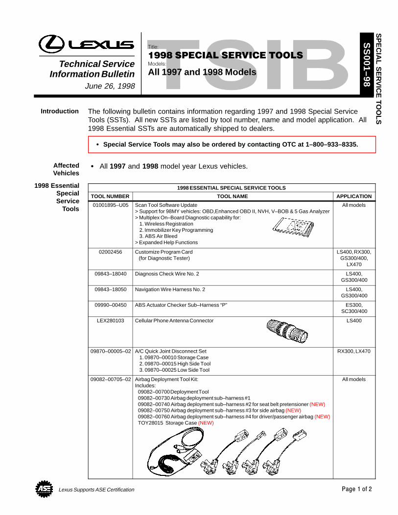
Lexus Supports ASE Certification Page 1 of 2
Title:
1998 SPECIAL SERVICE TOOLSModels:
All 1997 and 1998 ModelsTechnical Service
Information BulletinJune 26, 1998
SS
001–98
The following bulletin contains information regarding 1997 and 1998 Special ServiceTools (SSTs). All new SSTs are listed by tool number, name and model application. All1998 Essential SSTs are automatically shipped to dealers.
Special Service Tools may also be ordered by contacting OTC at 1–800–933–8335.
All 1997 and 1998 model year Lexus vehicles.
1998 ESSENTIAL SPECIAL SERVICE TOOLS
TOOL NUMBER TOOL NAME APPLICATION
01001895–U05 Scan Tool Software Update> Support for 98MY vehicles: OBD,Enhanced OBD II, NVH, V–BOB & 5 Gas Analyzer> Multiplex On–Board Diagnostic capability for:
1. Wireless Registration2. Immobilizer Key Programming3. ABS Air Bleed
> Expanded Help Functions
All models
02002456 Customize Program Card (for Diagnostic Tester)
LS400, RX300,GS300/400,
LX470
09843–18040 Diagnosis Check Wire No. 2 LS400,GS300/400
09843–18050 Navigation Wire Harness No. 2 LS400,GS300/400
09990–00450 ABS Actuator Checker Sub–Harness “P” ES300,SC300/400
LEX280103 Cellular Phone Antenna Connector LS400
09870–00005–02 A/C Quick Joint Disconnect Set1. 09870–00010 Storage Case2. 09870–00015 High Side Tool3. 09870–00025 Low Side Tool
RX300, LX470
09082–00705–02 Airbag Deployment Tool Kit:Includes:
09082–00700 Deployment Tool09082–00730 Airbag deployment sub–harness #109082–00740 Airbag deployment sub–harness #2 for seat belt pretensioner (NEW)09082–00750 Airbag deployment sub–harness #3 for side airbag (NEW)09082–00760 Airbag deployment sub–harness #4 for driver/passenger airbag (NEW)TOY28015 Storage Case (NEW)
All models
SP
EC
IAL S
ER
VIC
E TO
OLS
Introduction
AffectedVehicles
1998 EssentialSpecialService
Tools
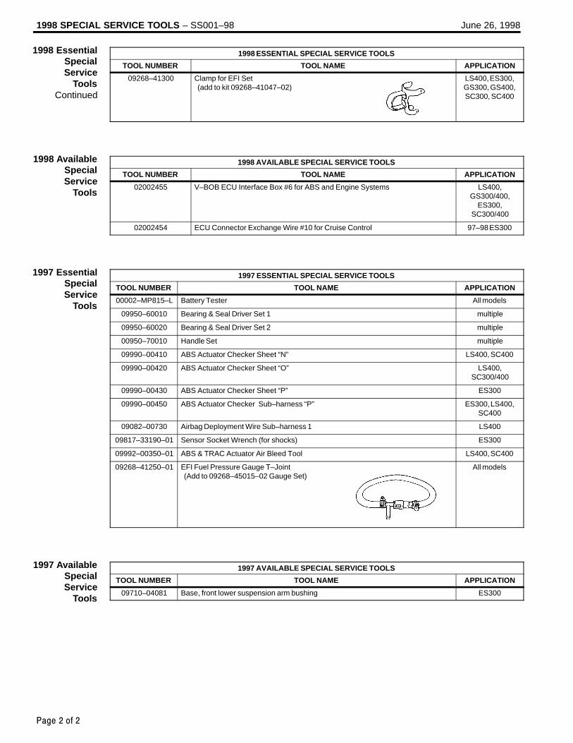
1998 SPECIAL SERVICE TOOLS – SS001–98 June 26, 1998
Page 2 of 2
1998 ESSENTIAL SPECIAL SERVICE TOOLS
TOOL NUMBER TOOL NAME APPLICATION
09268–41300 Clamp for EFI Set (add to kit 09268–41047–02)
LS400, ES300,GS300, GS400,SC300, SC400
1998 AVAILABLE SPECIAL SERVICE TOOLS
TOOL NUMBER TOOL NAME APPLICATION
02002455 V–BOB ECU Interface Box #6 for ABS and Engine Systems LS400,GS300/400,
ES300,SC300/400
02002454 ECU Connector Exchange Wire #10 for Cruise Control 97–98 ES300
1997 ESSENTIAL SPECIAL SERVICE TOOLS
TOOL NUMBER TOOL NAME APPLICATION
00002–MP815–L Battery Tester All models
09950–60010 Bearing & Seal Driver Set 1 multiple
09950–60020 Bearing & Seal Driver Set 2 multiple
00950–70010 Handle Set multiple
09990–00410 ABS Actuator Checker Sheet “N” LS400, SC400
09990–00420 ABS Actuator Checker Sheet “O” LS400,SC300/400
09990–00430 ABS Actuator Checker Sheet “P” ES300
09990–00450 ABS Actuator Checker Sub–harness “P” ES300, LS400,SC400
09082–00730 Airbag Deployment Wire Sub–harness 1 LS400
09817–33190–01 Sensor Socket Wrench (for shocks) ES300
09992–00350–01 ABS & TRAC Actuator Air Bleed Tool LS400, SC400
09268–41250–01 EFI Fuel Pressure Gauge T–Joint (Add to 09268–45015–02 Gauge Set)
All models
1997 AVAILABLE SPECIAL SERVICE TOOLS
TOOL NUMBER TOOL NAME APPLICATION
09710–04081 Base, front lower suspension arm bushing ES300
1998 EssentialSpecialService
ToolsContinued
1998 AvailableSpecialService
Tools
1997 EssentialSpecialService
Tools
1997 AvailableSpecialService
Tools

Toyota Supports ASE Certification Page 1 of 23
Title:
O2S TEST RESULTS (MODE 05)Models:
All ’96 – ’03 & ’04 RX 330Technical Service
BULLETINDecember 17, 2003
SS
002-03
This Service Bulletin contains Oxygen Sensor (O2S) Monitor threshold values for allmodels from 1996 to 2003 and some 2004 models. Starting in 2004, the O2S Monitorthreshold values can be found in the repair manual. These values are used whenanalyzing the O2S test results to determine the O2S condition.
All 1996 – 2003 model year Lexus vehicles. 2004 model year RX 330 vehicles.
Checking O2S Test Results
To view O2S test results, the O2S Monitor must be completed and the test results mustbe checked within the same key cycle. If the ignition key is cycled OFF, the O2S testresults will be set to the minimum or maximum limits, and all test results will be erased.The O2S test results are stored in the ECU (SAE term: Powertrain Control Module/PCM)when the monitor is complete. The test results are static and will not change once themonitor is complete.
The process for checking O2S test results is described in the following three basic steps:1. Completing the O2S Readiness Monitor (page 2).2. Accessing O2S Test Results (page 3).3. Comparing O2S Test Results to Failure Thresholds (page 4).
SPECIAL SERVICE TOOLS (SSTs) PART NUMBER QUANTITY
Lexus Diagnostic Tester Kit*(or any OBDII Scantool)
01001270 1
12 Megabyte Diagnostic Tester Program Cardwith version 10.1a Software (or later)* 01002593-005 1
* Essential SSTs.
NOTE:Additional Diagnostic Tester Kits, Program Cards or other SSTs may be ordered bycalling SPX/OTC at 1-800-933-8335.
OP CODE DESCRIPTION TIME OFP T1 T2
N/A Not Applicable to Warranty – – – –
SP
EC
IAL S
ER
VIC
E TO
OLSIntroduction
ApplicableVehicles
FunctionDescription
RequiredSSTs
WarrantyInformation

O2S TEST RESULTS (MODE 05) – SS002-03 December 17, 2003
Page 2 of 23
1. Clear any stored Diagnostic Trouble Codes (DTCs) using the Lexus Diagnostic Tester.2. Start the engine.3. Perform the drive pattern below to run and complete the Oxygen Sensor
(O2S) Monitor.
O2S Monitor Drive PatternECT: 167F (75C) or more
Vehicle Speed At Least 8 Times
48 km/h (30 mph)
Idling
At Least Twice
Accelerator PedalDepressing
Accelerator PedalReleasing (Fuel–Cut)
6 mph (10 km/h)
Time2 min.
or more40 sec
or more20 sec
or more10 sec
or more10 sec
or more
HINT:The O2S Monitor is completed when the following conditions are met: Two (2) minutes or more passed after the engine start. The Engine Coolant Temperature (ECT) is 167 F (75C) or more. Cumulative running time at 30 mph (48 km/h) or more exceeds 6 minutes. Vehicle is in closed loop. The fuel–cut is operated for 8 seconds or more (for Rear O2S Monitor).
A. Allow the engine to idle for two minutes.
B. Warm up the engine until the Engine Coolant Temperature (ECT) reaches 167F(75C).
C. Drive the vehicle over 30 mph (48 km/h) for more than 40 seconds.
D. Stop the vehicle and allow the engine to idle for more than 20 seconds.
E. Repeat steps C and D at least 8 times in one driving cycle. (Do not cycle the ignition key.)
In addition, perform the following steps for the Rear O2S Readiness Monitor:
A. Select second gear.
B. Allow the vehicle to run at 30 mph (48 km/h) or more.
C. Keep the accelerator pedal “off–idle” for more than 10 seconds.
D. Immediately after step C, release the accelerator pedal for at least 10 secondswithout depressing the brake pedal (to execute the fuel–cut).
E. Decelerate the vehicle until the vehicle speed reaches less than 6 mph (10 km/h).
F. Repeat steps B – E at least twice in one driving cycle.
CompletingO2S
ReadinessMonitor

O2S TEST RESULTS (MODE 05) – SS002-03 December 17, 2003
Page 3 of 23
1. On the Diagnostic Tester* screen,select the following menus:
DIAGNOSTICS CARB OBD II O2S TEST RESULTS
A list of the available oxygen sensorswill be displayed.
2. Select the desired oxygen sensor andpress Enter.
NOTE:The monitor result of the A/F sensor willnot be displayed. If you select“Bank 1–Sensor 1” or Bank 2–Sensor 1”for a vehicle equipped with an A/Fsensor, the Diagnostic Tester willdisplay “No parameter to display.”
3. Compare the test results with thevalues listed in the Failure Threshold Chart.
* Although this procedure references the LexusDiagnostic Tester, the O2S test results can be checked using a generic OBDII scantool. Refer to your OBDII scantool operator’s manual for specific procedures.
AccessingO2S Test
Results
O2S TEST RESULT Screen
01 BANK 1 – SENSOR 1
01 BANK 1 – SENSOR 2
01 BANK 2 – SENSOR 1
01 BANK 2 – SENSOR 2
TEST DATA Screen
LOW SW V 0.400 V
HIGH SW V 0.550 V
MIN O2S V 0.100 V
MAX O2S V 0.900 V
TIME $81 17

NOTE:Before the O2S Monitor completes or after the ignition switch is turned OFF, theDiagnostic Tester displays the viewable upper limit or a lower limit of the test value(example: 0 V, 1.275 V, 0 s [seconds], 10.2 s, 0 and 255).
O2S TEST RESULTS (MODE 05) – SS002-03 December 17, 2003
Page 4 of 23
1. Determine the correct O2S Failure Threshold Chart for your vehicle by looking in the“O2S Application Table,” pages 5 – 6 in this bulletin.
2. Select appropriate year, model, and engine for specified O2S Failure Threshold Chart.
3. Compare O2S test results with the specified O2S Failure Threshold Chart. It may benecessary to convert O2S test results to a specific measurement unit using theconversion factor that is supplied in the specified table. See example below:
Example:
A. The Diagnostic Tester displays“17” as a value of the “Time $81”(see illustration).
B. Find the Conversion Factor valueof “Time $81” in the O2S FailureThreshold chart below. 0.3906 is specified for Time $81 in this chart.
C. Multiply “17” in step “A” by 0.3906(Conversion Factor) in step “B.”17 x 0.3906 = 6.6 %
D. If the answer is within theStandard Value of TEST LIMIT,the “Time $81” can be confirmedto be normal.
Example of O2S Failure Threshold Chart:
TEST ID DESCRIPTION OF TEST DATACONVERSION
FACTORUNIT
STANDARD VALUEOF TEST LIMIT
Time$81
Percentage of monitoring timewhere Oxygen Sensor voltage isless than 0.05V
Multiply 0.3906 % Within 60%
ComparingO2S Test
Results toFailure
Thresholds
Example
LOW SW V 0.400 VHIGH SW V 0.550 VMIN O2S V 0.035 VMAX O2S V 0.835 VTime $81 17Time $84 84Time $85 79
NOTE: “LOW SW V” indicates the O2S
voltage when the O2S status changesfrom rich to lean.
“HIGH SW V” indicates the O2Svoltage when the O2S status changesfrom lean to rich.
If the O2S voltage is lower than“LOW SW V,” the O2S status is lean.
If the O2S voltage is higher than“HIGH SW V,” the O2S status is rich.

O2S TEST RESULTS (MODE 05) – SS002-03 December 17, 2003
Page 5 of 23
MODEL YEAR MODEL ENGINE CERTIFICATIONSEE CHART NO.
(TSB PAGE)
1996 ALL 50–State 1 (p. 7)
1997 ALL 50–State 1 (p. 7)
ES 300 1MZ FECalifornia 3 (p. 9)
ES 300 1MZ–FEFederal 1 (p. 7)
GS 300 2JZ–GE 50–State
1998GS 400 1UZ–FE 50–State
1998LS 400 1UZ–FE 50–State
2 (p 8)LX 470 2UZ–FE 50–State
2 (p. 8)
SC 300 2JZ–GE 50–State
SC 400 1UZ–FE 50–State
ES 300 1MZ–FE 50–State 3 (p. 9)
GS 300 2JZ–GE 50–State
GS 400 1UZ–FE 50–State2 (p 8)
1999LS 400 1UZ–FE 50–State
2 (p. 8)
1999LX 470 2UZ–FE 50–State
RX 300 1MZ–FE 50–State 3 (p. 9)
SC 300 2JZ–GE 50–State2 (p 8)
SC 400 1UZ–FE 50–State2 (p. 8)
ES 300 1MZ–FE 50–State 3 (p. 9)
GS 300 2JZ–GE 50–State
GS 400 1UZ–FE 50–State2 (p 8)
2000LS 400 1UZ–FE 50–State
2 (p. 8)
2000LX 470 2UZ–FE 50–State
RX 300 1MZ–FE 50–State 3 (p. 9)
SC 300 2JZ–GE 50–State2 (p 8)
SC 400 1UZ–FE 50–State2 (p. 8)
ES 300 1MZ–FE 50–State 3 (p. 9)
GS 300 2JZ–GE 50–State
GS 430 3UZ–FE 50–State
2001 IS 300 2JZ–GE 50–State 1 (p. 7)
LS 430 3UZ–FE 50–State
LX 470 2UZ–FE 50–State
RX 300 1MZ–FE 50–State 4 (p. 9)
O2SApplication
Table

O2S TEST RESULTS (MODE 05) – SS002-03 December 17, 2003
Page 6 of 23
MODEL YEAR MODEL ENGINE CERTIFICATIONSEE CHART NO.
(TSB PAGE)
ES 300 1MZ–FE 50–State 8 (p. 13)
GS 300 2JZ–GE 50–State 5 (p. 10)
GS 430 3UZ–FE 50–State 6 (p. 11)
2002IS 300 2JZ–GE 50–State 5 (p. 10)
2002LS 430 3UZ–FE 50–State 6 (p. 11)
LX 470 2UZ–FE 50–State 7 (p. 12)
RX 300 1MZ–FE 50–State 13 (p. 22)
SC 430 3UZ–FE 50–State 6 (p. 11)
ES 300 1MZ–FE 50–State 8 (p. 13)
GS 300 2JZ–GE 50–State 9 (p. 14–15)
GS 430 3UZ–FE 50–State 10 (p. 16–17)
GX 470 2UZ–FE 50–State 11 (p. 18–19)
2003 IS 300 2JZ–GE 50–State 9 (p. 14–15)
LS 430 3UZ–FE 50–State 10 (p. 16–17)
LX 470 2UZ–FE 50–State 12 (p. 20–21)
RX 300 1MZ–FE 50–State 13 (p. 22)
SC 430 3UZ–FE 50–State 10 (p. 16–17)
2004 RX 330 3MZ–FE 50–State 14 (p. 23)
O2SApplication
Table(Continued)

O2S TEST RESULTS (MODE 05) – SS002-03 December 17, 2003
Page 7 of 23
CHART 1:
Front O2S (Bank 1 Sensor 1 and Bank 2 Sensor 1) Voltage MonitorRelated DTCs: P0130, P0150, P2195, P2196, P2197 and P2198
TEST ID DESCRIPTION OF TEST DATACONVERSION
FACTORUNIT
STANDARD VALUEOF TEST LIMIT
Time$07
The minimum voltage during O2Smonitoring
N/A V Between 0 and 0.4 V
Time$08
The maximum voltage duringO2S monitoring
N/A V Between 0.55 and1.275 V
If the sensor voltage is out of the standard value, the ECM interprets this as a malfunction.
Front O2S (Bank 1 Sensor 1 and Bank 2 Sensor 1) Response MonitorRelated DTCs: P0133 and P0153
TEST ID DESCRIPTION OF TEST DATACONVERSION
FACTORUNIT
STANDARD VALUEOF TEST LIMIT
Time$31
Time to change from Lean(≤0.4 V) to Rich (≥0.55 V)
N/A Second Between 0 and1 second
Time$32
Time to change from Rich(≥0.55 V) to Lean (≥0.4 V)
N/A Second Between 0 and1 second
If the time required to change is out of the standard value, the ECM interprets this as a malfunction.
Rear O2S (Bank 1 Sensor 2 and Bank 2 Sensor 2) Voltage MonitorRelated DTCs: P0136 and P0156
TEST ID DESCRIPTION OF TEST DATACONVERSION
FACTORUNIT
STANDARD VALUEOF TEST LIMIT
Time$07
The minimum voltage during O2Smonitoring
N/A V Between 0 and 0.4 V
Time$08
The maximum voltage duringO2S monitoring
N/A V Between 0.5 and1.275 V
If the sensor voltage is out of the standard value, the ECM interprets this as a malfunction.
O2S FailureThreshold
Charts

O2S TEST RESULTS (MODE 05) – SS002-03 December 17, 2003
Page 8 of 23
CHART 2:
Front O2S (Bank 1 Sensor 1 and Bank 2 Sensor 1) Voltage MonitorRelated DTCs: P0130, P0150, P2195, P2196, P2197 and P2198
TEST ID DESCRIPTION OF TEST DATACONVERSION
FACTORUNIT
STANDARD VALUEOF TEST LIMIT
Time$07
The minimum voltage duringO2S monitoring
N/A V Between 0 and0.35 V
Time$08
The maximum voltage duringO2S monitoring
N/A V Between 0.55 and1.275 V
If the sensor voltage is out of the standard value, the ECM interprets this as a malfunction.
Front O2S (Bank 1 Sensor 1 and Bank 2 Sensor 1) Response MonitorRelated DTCs: P0133 and P0153
TEST ID DESCRIPTION OF TEST DATACONVERSION
FACTORUNIT
STANDARD VALUEOF TEST LIMIT
Time$31
Time to change from Lean(≤0.35 V) to Rich (≥0.55 V)
N/A Second Between 0 and1.1 seconds
Time$32
Time to change from Rich(≥0.55 V) to Lean (≥0.35 V)
N/A Second Between 0 and1.1 seconds
If the time required to change is out of the standard value, the ECM interprets this as a malfunction.
Rear O2S (Bank 1 Sensor 2 and Bank 2 Sensor 2) Voltage MonitorRelated DTCs: P0136 and P0156
TEST ID DESCRIPTION OF TEST DATACONVERSION
FACTORUNIT
STANDARD VALUEOF TEST LIMIT
Time$07
The minimum voltage duringO2S monitoring
N/A V Between 0 and 0.4 V
Time$08
The maximum voltage duringO2S monitoring
N/A V Between 0.5 and1.275 V
If the sensor voltage is out of the standard value, the ECM interprets this as a malfunction.
O2S FailureThreshold
Charts(Continued)

O2S TEST RESULTS (MODE 05) – SS002-03 December 17, 2003
Page 9 of 23
CHART 3:
Rear O2S (Bank 1 Sensor 2 and Bank 2 Sensor 2) Voltage MonitorRelated DTCs: P0136 and P0156
TEST ID DESCRIPTION OF TEST DATACONVERSION
FACTORUNIT
STANDARD VALUEOF TEST LIMIT
Time$07
The minimum voltage duringO2S monitoring
N/A V Between 0 and0.45 V
Time$08
The maximum voltage duringO2S monitoring
N/A V Between 0.6 and1.275 V
If the sensor voltage is out of the standard value, the ECM interprets this as a malfunction.
CHART 4:
Rear O2S (Bank 1 Sensor 2 and Bank 2 Sensor 2) Voltage MonitorRelated DTCs: P0136 and P0156
TEST ID DESCRIPTION OF TEST DATACONVERSION
FACTORUNIT
STANDARD VALUEOF TEST LIMIT
Time$07
The minimum voltage duringO2S monitoring
N/A V Between 0 and 0.5 V
Time$08
The maximum voltage duringO2S monitoring
N/A V Between 0.6 and1.275 V
If the sensor voltage is out of the standard value, the ECM interprets this as a malfunction.
O2S FailureThreshold
Charts(Continued)

O2S TEST RESULTS (MODE 05) – SS002-03 December 17, 2003
Page 10 of 23
CHART 5:
Front O2S (Bank 1 Sensor 1 and Bank 2 Sensor 1) Voltage MonitorRelated DTCs: P0130, P0150, P2195, P2196, P2197 and P2198
TEST ID DESCRIPTION OF TEST DATACONVERSION
FACTORUNIT
STANDARD VALUEOF TEST LIMIT
Time$07
The minimum voltage duringO2S monitoring
N/A V Between 0 and 0.4 V
Time$08
The maximum voltage duringO2S monitoring
N/A V Between 0.55 and1.275 V
If the sensor voltage is out of the standard value, the ECM interprets this as a malfunction.
Front O2S (Bank 1 Sensor 1 and Bank 2 Sensor 1) Response MonitorRelated DTCs: P0133 and P0153
TEST ID DESCRIPTION OF TEST DATACONVERSION
FACTORUNIT
STANDARD VALUEOF TEST LIMIT
Time$31
Time to change from Lean(≤0.4 V) to Rich (≥0.55 V)
N/A Second Between 0 and0.9 seconds
Time$32
Time to change from Rich(≥0.55 V) to Lean (≤0.4 V)
N/A Second Between 0 and0.9 seconds
If the time required to change is out of the standard value, the ECM interprets this as a malfunction.
Rear O2S (Bank 1 Sensor 2 and Bank 2 Sensor 2) Voltage MonitorRelated DTCs: P0136 and P0156
TEST ID DESCRIPTION OF TEST DATACONVERSION
FACTORUNIT
STANDARD VALUEOF TEST LIMIT
Time$07
The minimum voltage duringO2S monitoring
N/A V Between 0 and 0.4 V
Time$08
The maximum voltage duringO2S monitoring
N/A V Between 0.5 and1.275 V
If the sensor voltage is out of the standard value, the ECM interprets this as a malfunction.
Rear O2S (Bank 1 Sensor 2 and Bank 2 Sensor 2) Element MonitorRelated DTCs: P0136 and P0156
TEST ID DESCRIPTION OF TEST DATACONVERSION
FACTORUNIT
STANDARD VALUEOF TEST LIMIT
Time$81
Percentage of monitoring timewhere Oxygen Sensor voltage isless than 0.05 V
Multiply 0.3906 %
Between 0 and 80%(A/T)Between 0 and 90%(M/T)
Time$84
Percentage of monitoring timewhere Oxygen Sensor voltage is0.70 V or more
Multiply 0.3906 % Between 20 and100%
Time$85
Maximum Rich (≤0.45 V) time Multiply 0.2621 Second Between 20 and 66.8 seconds
If all the values (Time $81, Time $84 and Time $85) are out of the standard values, the ECMinterprets this as a malfunction.
O2S FailureThreshold
Charts(Continued)

O2S TEST RESULTS (MODE 05) – SS002-03 December 17, 2003
Page 11 of 23
CHART 6:
Rear O2S (Bank 1 Sensor 1 and Bank 2 Sensor 1) Voltage MonitorRelated DTCs: P0130, P0150, P2195, P2196, P2197 and P2198
TEST ID DESCRIPTION OF TEST DATACONVERSION
FACTORUNIT
STANDARD VALUEOF TEST LIMIT
Time$07
The minimum voltage duringO2S monitoring
N/A V Between 0 and 0.4 V
Time$08
The maximum voltage duringO2S monitoring
N/A V Between 0.55 and1.275 V
If the sensor voltage is out of the standard value, the ECM interprets this as a malfunction.
Front O2S (Bank 1 Sensor 1 and Bank 2 Sensor 1) Response MonitorRelated DTCs: P0133 and P0153
TEST ID DESCRIPTION OF TEST DATACONVERSION
FACTORUNIT
STANDARD VALUEOF TEST LIMIT
Time$31
Time to change from Lean(≤0.4 V) to Rich (≥0.55 V)
N/A Second Between 0 and0.9 seconds
Time$32
Time to change from Rich(≥0.55 V) to Lean (≤0.4 V)
N/A Second Between 0 and0.9 seconds
If the time required to change is out of the standard value, the ECM interprets this as a malfunction.
Rear O2S (Bank 1 Sensor 2 and Bank 2 Sensor 2) Voltage MonitorRelated DTCs: P0136 and P0156
TEST ID DESCRIPTION OF TEST DATACONVERSION
FACTORUNIT
STANDARD VALUEOF TEST LIMIT
Time$07
The minimum voltage duringO2S monitoring
N/A V Between 0 and 0.4 V
Time$08
The maximum voltage duringO2S monitoring
N/A V Between 0.5 and1.275 V
If the sensor voltage is out of the standard value, the ECM interprets this as a malfunction.
Rear O2S (Bank 1 Sensor 2 and Bank 2 Sensor 2) Element MonitorRelated DTCs: P0136 and P0156
TEST ID DESCRIPTION OF TEST DATACONVERSION
FACTORUNIT
STANDARD VALUEOF TEST LIMIT
Time$81
Percentage of monitoring timewhere Oxygen Sensor voltage isless than 0.05 V
Multiply 0.3906 % Between 0 and 60%
Time$84
Percentage of monitoring timewhere Oxygen Sensor voltage is0.70 V or more
Multiply 0.3906 % Between 20 and100%
Time$85
Maximum Rich (≤0.45 V) time Multiply 0.2621 Second Between 20 and 66.8 seconds
If all the values (Time $81, Time $84 and Time $85) are out of the standard values, the ECMinterprets this as a malfunction.
O2S FailureThreshold
Charts(Continued)

O2S TEST RESULTS (MODE 05) – SS002-03 December 17, 2003
Page 12 of 23
CHART 7:
Front O2S (Bank 1 Sensor 1 and Bank 2 Sensor 1) Voltage MonitorRelated DTCs: P0130, P0150, P2195, P2196, P2197 and P2198
TEST ID DESCRIPTION OF TEST DATACONVERSION
FACTORUNIT
STANDARD VALUEOF TEST LIMIT
Time$07
The minimum voltage duringO2S monitoring
N/A V Between 0 and 0.4 V
Time$08
The maximum voltage duringO2S monitoring
N/A V Between 0.55 and1.275 V
If the sensor voltage is out of the standard value, the ECM interprets this as a malfunction.
Front O2S (Bank 1 Sensor 1 and Bank 2 Sensor 1) Response MonitorRelated DTCs: P0133 and P0153
TEST ID DESCRIPTION OF TEST DATACONVERSION
FACTORUNIT
STANDARD VALUEOF TEST LIMIT
Time$31
Time to change from Lean(≤0.4 V) to Rich (≥0.55 V)
N/A Second Between 0 and0.9 seconds
Time$32
Time to change from Rich(≥0.55 V) to Lean (≤0.4 V)
N/A Second Between 0 and0.9 seconds
If the time required to change is out of the standard value, the ECM interprets this as a malfunction.
Rear O2S (Bank 1 Sensor 2 and Bank 2 Sensor 2) Voltage MonitorRelated DTCs: P0136 and P0156
TEST ID DESCRIPTION OF TEST DATACONVERSION
FACTORUNIT
STANDARD VALUEOF TEST LIMIT
Time$07
The minimum voltage duringO2S monitoring
N/A V Between 0 and 0.4 V
Time$08
The maximum voltage duringO2S monitoring
N/A V Between 0.5 and1.275 V
If the sensor voltage is out of the standard value, the ECM interprets this as a malfunction.
Rear O2S (Bank 1 Sensor 2 and Bank 2 Sensor 2) Element MonitorRelated DTCs: P0136 and P0156
TEST ID DESCRIPTION OF TEST DATACONVERSION
FACTORUNIT
STANDARD VALUEOF TEST LIMIT
Time$81
Percentage of monitoring timewhere Oxygen Sensor voltage isless than 0.05 V
Multiply 0.3906 % Between 0 and 90%
Time$84
Percentage of monitoring timewhere Oxygen Sensor voltage is0.70 V or more
Multiply 0.3906 % Between 20 and100%
Time$85
Maximum Rich (≤0.45 V) time Multiply 0.2621 Second Between 20 and 66.8 seconds
If all the values (Time $81, Time $84 and Time $85) are out of the standard values, the ECMinterprets this as a malfunction.
O2S FailureThreshold
Charts(Continued)

O2S TEST RESULTS (MODE 05) – SS002-03 December 17, 2003
Page 13 of 23
CHART 8:
Front O2S (Bank 1 Sensor 2 and Bank 2 Sensor 2) Voltage MonitorRelated DTCs: P0136 and P0156
TEST ID DESCRIPTION OF TEST DATACONVERSION
FACTORUNIT
STANDARD VALUEOF TEST LIMIT
Time$07
The minimum voltage duringO2S monitoring
N/A V Between 0 and 0.5 V
Time$08
The maximum voltage duringO2S monitoring
N/A V Between 0.6 and1.275 V
If the sensor voltage is out of the standard value, the ECM interprets this as a malfunction.
Rear O2S (Bank 1 Sensor 2 and Bank 2 Sensor 2) Element MonitorRelated DTCs: P0136 and P0156
TEST ID DESCRIPTION OF TEST DATACONVERSION
FACTORUNIT
STANDARD VALUEOF TEST LIMIT
Time$81
Percentage of monitoring timewhere Oxygen Sensor voltage isless than 0.05 V
Multiply 0.3906 % Between 0 and 95%
Time$84
Percentage of monitoring timewhere Oxygen Sensor voltage is0.70 V or more
Multiply 0.3906 % Between 20 and100%
Time$85
Maximum Rich (≤0.45 V) time Multiply 0.2621 Second Between 20 and 66.8 seconds
If all the values (Time $81, Time $84 and Time $85) are out of the standard values, the ECMinterprets this as a malfunction.
O2S FailureThreshold
Charts(Continued)

O2S TEST RESULTS (MODE 05) – SS002-03 December 17, 2003
Page 14 of 23
CHART 9:
Rear O2S (Bank 1 Sensor 1 and Bank 2 Sensor 1) Voltage MonitorRelated DTCs: P0130, P0150, P2195, P2196, P2197 and P2198
TEST ID DESCRIPTION OF TEST DATACONVERSION
FACTORUNIT
STANDARD VALUEOF TEST LIMIT
Time$07
The minimum voltage duringO2S monitoring
N/A V Between 0 and 0.4 V
Time$08
The maximum voltage duringO2S monitoring
N/A V Between 0.55 and1.275 V
If the sensor voltage is out of the standard value, the ECM interprets this as a malfunction.
Front O2S (Bank 1 Sensor 1 and Bank 2 Sensor 1) Response MonitorRelated DTCs: P0133 and P0153
TEST ID DESCRIPTION OF TEST DATACONVERSION
FACTORUNIT
STANDARD VALUEOF TEST LIMIT
Time$31
Time to change from Lean(≤0.4 V) to Rich (≥0.55 V)
N/A Second Between 0 and1 second
Time$32
Time to change from Rich(≥0.55 V) to Lean (≤0.4 V)
N/A Second Between 0 and1 second
If the time required to change is out of the standard value, the ECM interprets this as a malfunction.
Front O2S (Bank 1 Sensor 1 and Bank 2 Sensor 1) Frequency Monitor DuringEngine IdlingRelated DTCs: P0133 and P0153
TEST ID DESCRIPTION OF TEST DATACONVERSION
FACTORUNIT
STANDARD VALUEOF TEST LIMIT
Time$33
Average Lean (≤0.4 V) time ofone waveform cycle
N/A Second
Bank 1:Between 0 and3.45 secondsBank 2:Between 0 and3.7 seconds
Time$34
Average Rich (≥0.55 V) time ofone waveform cycle
N/A Second
Bank 1:Between 0 and3.45 secondsBank 2:Between 0 and3.7 seconds
If the sum of Time $33 and Time $34 is out of the standard value, the ECM interprets this as amalfunction.
O2S FailureThreshold
Charts(Continued)

O2S TEST RESULTS (MODE 05) – SS002-03 December 17, 2003
Page 15 of 23
CHART 9 (Continued):
Front O2S (Bank 1 Sensor 1 and Bank 2 Sensor 1) Frequency Monitor DuringVehicle RunningRelated DTCs: P0133 and P0153
TEST ID DESCRIPTION OF TEST DATACONVERSION
FACTORUNIT
STANDARD VALUEOF TEST LIMIT
Time$35
Average Lean (≤0.4 V) time ofone waveform cycle N/A Second
Bank 1:Between 0 and0.73 secondsBank 2:Between 0 and0.75 seconds (varies depending on feedbackcompensation factor)
Time$36
Average Rich (≥0.55 V) time ofone waveform cycle N/A Second
Bank 1:Between 0 and0.73 secondsBank 2:Between 0 and0.75 seconds (varies depending on feedbackcompensation factor)
If the sum of Time $35 and Time $36 is out of the standard value, the ECM interprets this as amalfunction.
Rear O2S (Bank 1 Sensor 2 and Bank 2 Sensor 2) Voltage MonitorRelated DTCs: P0136 and P0156
TEST ID DESCRIPTION OF TEST DATACONVERSION
FACTORUNIT
STANDARD VALUEOF TEST LIMIT
Time$07
The minimum voltage duringO2S monitoring
N/A V Between 0 and 0.4 V
Time$08
The maximum voltage duringO2S monitoring
N/A V Between 0.5 and1.275 V
If the sensor voltage is out of the standard value, the ECM interprets this as a malfunction.
Rear O2S (Bank 1 Sensor 2 and Bank 2 Sensor 2) Element MonitorRelated DTCs: P0136 and P0156
TEST ID DESCRIPTION OF TEST DATACONVERSION
FACTORUNIT
STANDARD VALUEOF TEST LIMIT
Time$81
Percentage of monitoring timewhere Oxygen Sensor voltage isless than 0.05 V
Multiply 0.3906 % Between 0 and 90%
Time$84
Percentage of monitoring timewhere Oxygen Sensor voltage is0.70 V or more
Multiply 0.3906 % Between 20 and100%
Time$85
Maximum Rich (≤0.45 V) time Multiply 0.2621 Second Between 20 and 66.8 seconds
If all the values (Time $81, Time $84 and Time $85) are out of the standard values, the ECMinterprets this as a malfunction.
O2S FailureThreshold
Charts(Continued)

O2S TEST RESULTS (MODE 05) – SS002-03 December 17, 2003
Page 16 of 23
CHART 10:
Front O2S (Bank 1 Sensor 1 and Bank 2 Sensor 1) Voltage MonitorRelated DTCs: P0130, P0150, P2195, P2196, P2197 and P2198
TEST ID DESCRIPTION OF TEST DATACONVERSION
FACTORUNIT
STANDARD VALUEOF TEST LIMIT
Time$07
The minimum voltage duringO2S monitoring
N/A V Between 0 and 0.4 V
Time$08
The maximum voltage duringO2S monitoring
N/A V Between 0.55 and1.275 V
If the sensor voltage is out of the standard value, the ECM interprets this as a malfunction.
Front O2S (Bank 1 Sensor 1 and Bank 2 Sensor 1) Response MonitorRelated DTCs: P0133 and P0153
TEST ID DESCRIPTION OF TEST DATACONVERSION
FACTORUNIT
STANDARD VALUEOF TEST LIMIT
Time$31
Time to change from Lean(≤0.4 V) to Rich (≥0.55 V)
N/A Second Between 0 and0.9 seconds
Time$32
Time to change from Rich(≥0.55 V) to Lean (≤0.4 V)
N/A Second Between 0 and0.9 seconds
If the time required to change is out of the standard value, the ECM interprets this as a malfunction.
Front O2S (Bank 1 Sensor 1 and Bank 2 Sensor 1) Frequency Monitor DuringEngine IdlingRelated DTCs: P0133 and P0153
TEST ID DESCRIPTION OF TEST DATACONVERSION
FACTORUNIT
STANDARD VALUEOF TEST LIMIT
Time$33
Average Lean (≤0.4 V) time ofone waveform cycle
N/A Second Between 0 and3 seconds
Time$34
Average Rich (≥0.55 V) time ofone waveform cycle
N/A Second Between 0 and3 seconds
If the sum of Time $33 and Time $34 is out of the standard value, the ECM interprets this as amalfunction.
O2S FailureThreshold
Charts(Continued)

O2S TEST RESULTS (MODE 05) – SS002-03 December 17, 2003
Page 17 of 23
CHART 10 (Continued):
Front O2S (Bank 1 Sensor 1 and Bank 2 Sensor 1) Frequency Monitor DuringEngine IdlingRelated DTCs: P0133 and P0153
TEST ID DESCRIPTION OF TEST DATACONVERSION
FACTORUNIT
STANDARD VALUEOF TEST LIMIT
Time$35
Average Lean (≤0.4 V) time ofone waveform cycle
N/A Second
Between 0 and0.75 seconds (varies depending on feedbackcompensation factor)
Time$36
Average Rich (≥0.55 V) time ofone waveform cycle
N/A Second
Between 0 and0.75 seconds (varies depending on feedbackcompensation factor)
If the sum of Time $35 and Time $36 is out of the standard value, the ECM interprets this as amalfunction.
Rear O2S (Bank 1 Sensor 2 and Bank 2 Sensor 2) Voltage MonitorRelated DTCs: P0136 and P0156
TEST ID DESCRIPTION OF TEST DATACONVERSION
FACTORUNIT
STANDARD VALUEOF TEST LIMIT
Time$07
The minimum voltage duringO2S monitoring
N/A V Between 0 and 0.4 V
Time$08
The maximum voltage duringO2S monitoring
N/A V Between 0.5 and1.275 V
If the sensor voltage is out of the standard value, the ECM interprets this as a malfunction.
Rear O2S (Bank 1 Sensor 2 and Bank 2 Sensor 2) Element MonitorRelated DTCs: P0136 and P0156
TEST ID DESCRIPTION OF TEST DATACONVERSION
FACTORUNIT
STANDARD VALUEOF TEST LIMIT
Time$81
Percentage of monitoring timewhere Oxygen Sensor voltage isless than 0.05 V
Multiply 0.3906 % Between 0 and 60%
Time$84
Percentage of monitoring timewhere Oxygen Sensor voltage is0.70 V or more
Multiply 0.3906 % Between 20 and100%
Time$85
Maximum Rich (≤0.45 V) time Multiply 0.2621 Second Between 20 and 66.8 seconds
If all the values (Time $81, Time $84 and Time $85) are out of the standard values, the ECMinterprets this as a malfunction.
O2S FailureThreshold
Charts(Continued)

O2S TEST RESULTS (MODE 05) – SS002-03 December 17, 2003
Page 18 of 23
CHART 11:
Front O2S (Bank 1 Sensor 1 and Bank 2 Sensor 1) Voltage MonitorRelated DTCs: P0130, P0150, P2195, P2196, P2197 and P2198
TEST ID DESCRIPTION OF TEST DATACONVERSION
FACTORUNIT
STANDARD VALUEOF TEST LIMIT
Time$07
The minimum voltage duringO2S monitoring
N/A V Between 0 and 0.4 V
Time$08
The maximum voltage duringO2S monitoring
N/A V Between 0.55 and1.275 V
If the sensor voltage is out of the standard value, the ECM interprets this as a malfunction.
Front O2S (Bank 1 Sensor 1 and Bank 2 Sensor 1) Response MonitorRelated DTCs: P0133 and P0153
TEST ID DESCRIPTION OF TEST DATACONVERSION
FACTORUNIT
STANDARD VALUEOF TEST LIMIT
Time$31
Time to change from Lean(≤0.4 V) to Rich (≥0.55 V)
N/A Second Between 0 and 0.9 seconds
Time$32
Time to change from Rich(≥0.55 V) to Lean (≤0.4 V)
N/A Second Between 0 and 0.9 seconds
If the time required to change is out of the standard value, the ECM interprets this as a malfunction.
Front O2S (Bank 1 Sensor 1 and Bank 2 Sensor 1) Frequency Monitor DuringEngine IdlingRelated DTCs: P0133 and P0153
TEST ID DESCRIPTION OF TEST DATACONVERSION
FACTORUNIT
STANDARD VALUEOF TEST LIMIT
Time$33
Average Lean (≤0.4 V) time ofone waveform cycle
N/A Second Between 0 and2.8 seconds
Time$34
Average Rich (≥0.55 V) time ofone waveform cycle
N/A Second Between 0 and2.8 seconds
If the sum of Time $33 and Time $34 is out of the standard value, the ECM interprets this as amalfunction.
O2S FailureThreshold
Charts(Continued)

O2S TEST RESULTS (MODE 05) – SS002-03 December 17, 2003
Page 19 of 23
CHART 11 (Continued):
Front O2S (Bank 1 Sensor 1 and Bank 2 Sensor 1) Frequency Monitor DuringVehicle RunningRelated DTCs: P0133 and P0153
TEST ID DESCRIPTION OF TEST DATACONVERSION
FACTORUNIT
STANDARD VALUEOF TEST LIMIT
Time$35
Average Lean (≤0.4 V) time ofone waveform cycle
N/A Second
Between 0 and0.75 seconds (varies depending on feedbackcompensation factor)
Time$36
Average Rich (≥0.55 V) time ofone waveform cycle
N/A Second
Between 0 and0.75 seconds (varies depending on feedbackcompensation factor)
If the sum of Time $35 and Time $36 is out of the standard value, the ECM interprets this as amalfunction.
Rear O2S (Bank 1 Sensor 2 and Bank 2 Sensor 2) Voltage MonitorRelated DTCs: P0136 and P0156
TEST ID DESCRIPTION OF TEST DATACONVERSION
FACTORUNIT
STANDARD VALUEOF TEST LIMIT
Time$07
The minimum voltage duringO2S monitoring
N/A V Between 0 and 0.4 V
Time$08
The maximum voltage duringO2S monitoring
N/A V Between 0.5 and1.275 V
If the sensor voltage is out of the standard value, the ECM interprets this as a malfunction.
Rear O2S (Bank 1 Sensor 2 and Bank 2 Sensor 2) Element MonitorRelated DTCs: P0136 and P0156
TEST ID DESCRIPTION OF TEST DATACONVERSION
FACTORUNIT
STANDARD VALUEOF TEST LIMIT
Time$81
Percentage of monitoring timewhere Oxygen Sensor voltage isless than 0.05 V
Multiply 0.3906 % Between 0 and 60%
Time$84
Percentage of monitoring timewhere Oxygen Sensor voltage is0.70 V or more
Multiply 0.3906 % Between 20 and100%
Time$85
Maximum Rich (≤0.45 V) time Multiply 0.2621 Second Between 20 and 66.8 seconds
If all the values (Time $81, Time $84 and Time $85) are out of the standard values, the ECMinterprets this as a malfunction.
O2S FailureThreshold
Charts(Continued)

O2S TEST RESULTS (MODE 05) – SS002-03 December 17, 2003
Page 20 of 23
CHART 12:
Front O2S (Bank 1 Sensor 1 and Bank 2 Sensor 1) Voltage MonitorRelated DTCs: P0130, P0150, P2195, P2196, P2197 and P2198
TEST ID DESCRIPTION OF TEST DATACONVERSION
FACTORUNIT
STANDARD VALUEOF TEST LIMIT
Time$07
The minimum voltage duringO2S monitoring
N/A V Between 0 and 0.4 V
Time$08
The maximum voltage duringO2S monitoring
N/A V Between 0.55 and1.275 V
If the sensor voltage is out of the standard value, the ECM interprets this as a malfunction.
Front O2S (Bank 1 Sensor 1 and Bank 2 Sensor 1) Response MonitorRelated DTCs: P0133 and P0153
TEST ID DESCRIPTION OF TEST DATACONVERSION
FACTORUNIT
STANDARD VALUEOF TEST LIMIT
Time$31
Time to change from Lean(≤0.4 V) to Rich (≥0.55 V)
N/A Second Between 0 and 0.9 seconds
Time$32
Time to change from Rich(≥0.55 V) to Lean (≤0.4 V)
N/A Second Between 0 and 0.9 seconds
If the time required to change is out of the standard value, the ECM interprets this as a malfunction.
Front O2S (Bank 1 Sensor 1 and Bank 2 Sensor 1) Frequency Monitor DuringEngine IdlingRelated DTCs: P0133 and P0153
TEST ID DESCRIPTION OF TEST DATACONVERSION
FACTORUNIT
STANDARD VALUEOF TEST LIMIT
Time$33
Average Lean (≤0.4 V) time ofone waveform cycle
N/A Second Between 0 and2.8 seconds
Time$34
Average Rich (≥0.55 V) time ofone waveform cycle
N/A Second Between 0 and2.8 seconds
If the sum of Time $33 and Time $34 is out of the standard value, the ECM interprets this as amalfunction.
O2S FailureThreshold
Charts(Continued)

O2S TEST RESULTS (MODE 05) – SS002-03 December 17, 2003
Page 21 of 23
CHART 12 (Continued):
Front O2S (Bank 1 Sensor 1 and Bank 2 Sensor 1) Frequency Monitor DuringVehicle RunningRelated DTCs: P0133 and P0153
TEST ID DESCRIPTION OF TEST DATACONVERSION
FACTORUNIT
STANDARD VALUEOF TEST LIMIT
Time$35
Average Lean (≤0.4 V) time ofone waveform cycle
N/A Second
Between 0 and0.75 seconds (varies depending on feedbackcompensation factor)
Time$36
Average Rich (≥0.55 V) time ofone waveform cycle
N/A Second
Between 0 and0.75 seconds (varies depending on feedbackcompensation factor)
If the sum of Time $35 and Time $36 is out of the standard value, the ECM interprets this as amalfunction.
Rear O2S (Bank 1 Sensor 2 and Bank 2 Sensor 2) Voltage MonitorRelated DTCs: P0136 and P0156
TEST ID DESCRIPTION OF TEST DATACONVERSION
FACTORUNIT
STANDARD VALUEOF TEST LIMIT
Time$07
The minimum voltage duringO2S monitoring
N/A V Between 0 and 0.4 V
Time$08
The maximum voltage duringO2S monitoring
N/A V Between 0.5 and1.275 V
If the sensor voltage is out of the standard value, the ECM interprets this as a malfunction.
Rear O2S (Bank 1 Sensor 2 and Bank 2 Sensor 2) Element MonitorRelated DTCs: P0136 and P0156
TEST ID DESCRIPTION OF TEST DATACONVERSION
FACTORUNIT
STANDARD VALUEOF TEST LIMIT
Time$81
Percentage of monitoring timewhere Oxygen Sensor voltage isless than 0.5 V
Multiply 0.3906 % Between 0 and 90%
Time$84
Percentage of monitoring timewhere Oxygen Sensor voltage is0.70 V or more
Multiply 0.3906 % Between 20 and100%
Time$85
Maximum Rich (≥0.45 V) time Multiply 0.2621 Second Between 20 and 66.8 seconds
If all the values (Time $81, Time $84 and Time $85) are out of the standard values, the ECMinterprets this as a malfunction.
O2S FailureThreshold
Charts(Continued)

O2S TEST RESULTS (MODE 05) – SS002-03 December 17, 2003
Page 22 of 23
CHART 13:
Rear O2S (Bank 1 Sensor 2 and Bank 2 Sensor 2) Voltage MonitorRelated DTCs: P0136 and P0156
TEST ID DESCRIPTION OF TEST DATACONVERSION
FACTORUNIT
STANDARD VALUEOF TEST LIMIT
Time$07
The minimum voltage duringO2S monitoring
N/A V Between 0 and 0.4 V
Time$08
The maximum voltage duringO2S monitoring
N/A V Between 0.6 and1.275 V
If the sensor voltage is out of the standard value, the ECM interprets this as a malfunction.
Rear O2S (Bank 1 Sensor 2 and Bank 2 Sensor 2) Element MonitorRelated DTCs: P0136 and P0156
TEST ID DESCRIPTION OF TEST DATACONVERSION
FACTORUNIT
STANDARD VALUEOF TEST LIMIT
Time$81
Percentage of monitoring timewhere Oxygen Sensor voltage isless than 0.5 V
Multiply 0.3906 % Between 0 and 60%
Time$84
Percentage of monitoring timewhere Oxygen Sensor voltage is0.70 V or more
Multiply 0.3906 % Between 20 and100%
Time$85
Maximum Rich (≥0.45 V) time Multiply 0.2621 Second Between 20 and 66.8 seconds
If all the values (Time $81, Time $84 and Time $85) are out of the standard values, the ECMinterprets this as a malfunction.
O2S FailureThreshold
Charts(Continued)

O2S TEST RESULTS (MODE 05) – SS002-03 December 17, 2003
Page 23 of 23
CHART 14:
Rear O2S (Bank 1 Sensor 2 and Bank 2 Sensor 2) Voltage MonitorRelated DTCs: P0136 and P0156
TEST ID DESCRIPTION OF TEST DATACONVERSION
FACTORUNIT
STANDARD VALUEOF TEST LIMIT
Time$07
The minimum voltage duringO2S monitoring
N/A V Between 0 and0.45 V
Time$08
The maximum voltage duringO2S monitoring
N/A V Between 0.5 and1.275 V
If the sensor voltage is out of the standard value, the ECM interprets this as a malfunction.
Rear O2S (Bank 1 Sensor 2 and Bank 2 Sensor 2) Element MonitorRelated DTCs: P0136 and P0156
TEST ID DESCRIPTION OF TEST DATACONVERSION
FACTORUNIT
STANDARD VALUEOF TEST LIMIT
Time$81
Percentage of monitoring timewhere Oxygen Sensor voltage isless than 0.5 V
Multiply 0.3906 % Between 0 and 80%
Time$84
Percentage of monitoring timewhere Oxygen Sensor voltage is0.70 V or more
Multiply 0.3906 % Between 20 and100%
Time$85
Maximum Rich (≥0.45 V) time Multiply 0.2621 Second Between 20 and 66.8 seconds
If all the values (Time $81, Time $84 and Time $85) are out of the standard values, the ECMinterprets this as a malfunction.
O2S FailureThreshold
Charts(Continued)

Lexus Supports ASE Certification Page 1 of 10
Title:
MIDTRONICS BATTERY TESTER
SOFTWARE UPDATEModels:
All Models & Model Years Through Current
Technical ServiceInformation Bulletin
June 7, 2002
SS
002-02
The internal software of the Midtronics Battery Tester can now be periodically updated tosupport future models. New updates will include new battery warranty codes and testinginformation.
The Technical Information System (TIS) will be the primary distribution method for batterytester software updates. Utilizing the new Midtronics Update Wizard (MUW) and the newessential SST (Midtronics Battery Tester Adapter), you will be able to quickly and easilyupdate your Midtronics Battery Tester.
This bulletin will show you how to use and install the Midtronics Update Wizard to updatethe Midtronics tester software.
All models and model years through current.
SPECIAL SERVICE TOOLS (SSTs) PART NUMBER QUANTITY
Midtronics Battery Tester* 00002–MP815–L 1
Midtronics Battery Tester Adapter* 00002–DMPUC 1
* Essential SSTs.
OP CODE DESCRIPTION TIME OPN T1 T2
N/A Not Applicable to Warranty – – – –
The Midtronics Battery Tester Software Update is a 2-step process:
1. Installing the Midtronics Update Wizard (MUW).The Midtronics Update Wizard (MUW) is an application that only needs to be installedon the PC one time. This bulletin will provide the steps to install the MUW.
2. Using the Midtronics Update Wizard (MUW).The Midtronics Update Wizard (MUW) will be used with each battery tester softwareupdate. The Update Wizard will walk you through each step to connect the PC to thetester and perform the update.
SP
EC
IAL S
ER
VIC
E TO
OLSIntroduction
ApplicableVehicles
RequiredTools &Material
WarrantyInformation
ProcessOverview

MIDTRONICS BATTERY TESTER SOFTWARE UPDATE – SS002-02 June 7, 2002
Page 2 of 10
Before Installation or Use of the Midtronics Update Wizard (MUW):
Steps A and B are required to begin the update process. (Refer to Figure 1.)
A. Open TIS (Technical Information System) and go to the “Diagnostics” section.
B. Click on the text “Midtronics Battery Tester Software.”
A
FIGURE 1.
B
OperationProcedure:
Preparation

MIDTRONICS BATTERY TESTER SOFTWARE UPDATE – SS002-02 June 7, 2002
Page 3 of 10
1. Installing the Midtronics Update Wizard (MUW).
NOTE:The Midtronics Update Wizard only needs to be installed once and must be installedbefore the rest of the update process can take place. If this step is already complete,continue on to step 2.
A. Click on the text “Install MUW.” (Figure 2.)
B. The file download window will appear. Click on “Run this program from it’s currentlocation.”
C. Click the “OK” button.
D. Allow the Update Wizard to perform its self–installation. This will take only a fewminutes.
B
C
FIGURE 2.
A
OperationProcedure

MIDTRONICS BATTERY TESTER SOFTWARE UPDATE – SS002-02 June 7, 2002
Page 4 of 10
2. Using the Midtronics Update Wizard (MUW).
A. Click on the latest version of production software. (Figure 3.) This will begin thesoftware update process.
B. The next screen to appear will be the first screen of the software update. Click“Next” to continue.
A
FIGURE 3.
B
OperationProcedure(Continued)

MIDTRONICS BATTERY TESTER SOFTWARE UPDATE – SS002-02 June 7, 2002
Page 5 of 10
C. Enter the serial number of the battery tester then click “OK.” (Figure 4.)
FIGURE 4.
C
OperationProcedure(Continued)

MIDTRONICS BATTERY TESTER SOFTWARE UPDATE – SS002-02 June 7, 2002
Page 6 of 10
D. Connect the Midtronics Battery Tester to TIS as instructed (Figure 5), then click“Next.”
NOTE:Connecting the Midtronics Battery Tester to the TIS station will require the use of SST00002–DMPUC. This is an adapter that allows the TIS RS–232 cable to plug into theBattery Tester. (Figure 5.)
FIGURE 5.
D
OperationProcedure(Continued)

MIDTRONICS BATTERY TESTER SOFTWARE UPDATE – SS002-02 June 7, 2002
Page 7 of 10
E. Follow the instructions to put the Midtronics Battery Tester into the correct mode(Figure 6), then click “Next.”
FIGURE 6.
E
OperationProcedure(Continued)

MIDTRONICS BATTERY TESTER SOFTWARE UPDATE – SS002-02 June 7, 2002
Page 8 of 10
F. Confirm the software version and click “Next.” (Figure 7.)
FIGURE 7.
F
Figures 7–1 and 7–2 are confirmation dialogs that will pop up over the UpdateInformation window (Figure 7) when:
The update file is an older revision level than that found in the battery tester(Figure 7–1) or
The update file is the same revision level as that found in the tester(Figure 7–2).
Click the “Yes” button to clear the pop–up dialog and continue with the update.
FIGURE 7–1. FIGURE 7–2.
OperationProcedure(Continued)

MIDTRONICS BATTERY TESTER SOFTWARE UPDATE – SS002-02 June 7, 2002
Page 9 of 10
G. The Midtronics Update Wizard (MUW) will now update the Midtronics BatteryTester software. (Figure 8.)
NOTE:Do not interrupt this process (it will take approximately 5 minutes).
FIGURE 8.
OperationProcedure(Continued)

MIDTRONICS BATTERY TESTER SOFTWARE UPDATE – SS002-02 June 7, 2002
Page 10 of 10
H. Upon successful completion, the Update Results screen will display “No errors”and the update is now complete. Click on the “Exit” button. (Figure 9.)
FIGURE 9.
H
Your Midtronics Battery Tester is now updated and ready for use.
NOTE:BE SURE TO REGULARLY CHECK TIS FOR FUTURE UPDATES: The Midtronics Battery Tester OE Stock Number Card will no longer be printed and
shipped. It will be distributed through TIS from now on. Latest versions of Tester update software will be available on TIS.
OperationProcedure(Continued)

Page 1 of 1Lexus Supports ASE Certification
Title:
DIAGNOSTIC TESTER COMMUNICATION
ERROR WITH T.I.S.Models:
All Models
Technical ServiceInformation Bulletin
December 8, 2000
SS
003-00
Certain Diagnostic Testers (SST P/N 02002019) may experience a communication error with the Technical Information System (T.I.S.). To correct this condition, the testermanufacturer, Vetronix Corporation, will recall and update affected units. The followingexplains how to determine which Diagnostic Testers may exhibit this problem and outlines the procedure to return the tester for repair.
Diagnostic Testers within the serial number range below are known to experience thesecommunication errors.
STARTING SERIAL NUMBER ENDING SERIAL NUMBER
31 000000 31 000100
1. Determine the Diagnostic Tester serialnumber located on the back of the tester(see Figure 1).
2. If the serial number is within the rangelisted above, call Vetronix ToyotaCustomer Service at 1-800-321-4889,ext. 3123, to obtain a pre-paid shippingpackage for the Diagnostic Tester.
3. The shipping package will arrive within2 business days. Secure the tester inthe provided package following theenclosed shipping instructions.
Diagnostic Testers are guaranteed to bereturned within 3 business days fromreceipt at Vetronix (except overholidays).
NOTE:This update will be performedfree of charge.
Diagnostic Testers outside of the serial number range above are not affected and do not needthis repair. If a Diagnostic Tester outside this range experiences a similar problem, please callDealer Daily Support at 1-877-DL-DAILY or Vetronix Toyota Customer Service at1-800-321-4889, ext. 3123.
OP CODE DESCRIPTION TIME OPN T1 T2
N/A Not Applicable to Warranty – – – –
SP
EC
IAL S
ER
VIC
E TO
OLSIntroduction
ApplicableDiagnostic
Testers
RepairProcedure Figure 1
Back View of Diagnostic Tester
S/N 31 000100
WarrantyInformation

Page 1 of 1Lexus Supports ASE Certification
Title:
STEERING WHEEL NUT SERVICE
SPECIFICATIONModels:
All Applicable Models
Technical ServiceInformation Bulletin
February 16, 2001
ST
001-01
To make the steering wheel installation procedure similar for all models, the steeringwheel nut tightening torque has been standardized.
MODEL MODEL YEARS
LS 400 UCF10, 20 1990 – 2000
SC 400/300 JZZ31, UZZ30 1992 – 2000
GS 400/300 JZS147, 160, UZS160 1993 – 2000
ES 300 MCV10, 20 1994 – 2000
LX 450 FZJ80 1996 – 1997
LX 470 UZJ100 1998 – 2000
RX 300 MCU10, 15 1999 – 2000
IS 300 JCE10 2001
Steering WheelInstallation Nut
Steering WheelLowerNo. 2 Cover
Steering WheelLowerNo. 3 Cover
Steering Wheel Pad
Steering Wheel
Steering Column
35 Nm (360 kgf cm, 26 ft lbf)
50 Nm (510 kgf cm, 37 ft lbf)
OP CODE DESCRIPTION TIME OPN T1 T2
N/A Not Applicable to Warranty – – – –
ST
EE
RIN
G
Introduction
ApplicableVehicles
ServiceInformation
WarrantyInformation

DATE: MARCH 22, 1996
STEERING GEAR/STEERING WHEEL REMOVAL AND INSTALLATION Page 1 of 4
Anytime the steering gear is removed on a vehicle equipped with an SRS airbag, the steering wheel mustalso be removed. Use of the following steps for reinstallation and re–centering of the steering wheel willprevent possible damage to the spiral cable.
REQUIRED STEPS FOR STEERING GEAR REMOVAL AND INSTALLATION:
Removal: Place front wheels facing straight ahead.
Remove the steering wheel pad.
Remove the steering wheel.
Installation:
Place front wheels facing straight ahead.
Center the spiral cable.
Install the steering wheel.
Install the steering wheel pad.
STEERING GEAR/STEERING WHEEL REMOVAL PROCEDURES:
Follow the steps below to remove the steering wheel, before removing the steering gear, from the vehicle.
1. Place front wheels in the straight ahead position.
2. With ignition switch in lock position, disconnect the negative terminal of the battery.
3. Remove Steering wheel pad.
NOTICE: If the airbag connector is disconnected with the ignition switch at “ON” or “ACC,” a “Diagnostic Trouble Code” will be recorded.
Never use airbag parts from another vehicle. When replacing parts, replace with new parts.
a. Remove the steering wheel lower cover.
REF: STEERING
NO: ST001–96
MODEL: ALL MODELS

STEERING GEAR/STEERING WHEEL REMOVAL AND INSTALLATION Page 2 of 4
STEERING GEAR/STEERING WHEEL REMOVAL PROCEDURES (CONT’D):
b. Using a torx socket wrench, loosen the torx screws until the groove alongthe screw circumference catches onthe screw case. SST 09042–00010.(See Fig. 1)
c. Pull the wheel pad away from the steering wheel and disconnect the airbag connector. (See Fig. 2)
CAUTION: When storing the wheel pad, keep the upper surface of the pad facing up.
Never disassemble the wheel pad.
NOTICE: When removing the wheel pad, take care not to pull the airbag wiring harness.
4. Remove the steering wheel.
a. Disconnect the spiral cable connector.
b. Remove the wheel set nut.
c. Place matchmarks on the wheel andsteering main shaft. (See Fig. 3)
d. Using the appropriate SST, remove the wheel. SST 09950–50010 (set includes 09951–05010,
09952–05010, 09953–05020, 09954–05020)
For further disassembly of the steering column,refer to the Steering (SR) section of the RepairManual.
STEERING GEAR/STEERING WHEEL INSTALLATION PROCEDURES:
Follow the steps below to install the steering wheel, after installing the steering gear.
1. Place front wheels in the straight ahead position.
Fig. 1
Torx Screw Screw Case
Airbag Connector
Fig. 2
Fig. 3
Matchmarks
SST

STEERING GEAR/STEERING WHEEL REMOVAL AND INSTALLATION Page 3 of 4
2. Center spiral cable.
a. Turn the cable counterclockwise by hand untilit becomes harder to turn.
b. Then rotate the cable clockwise about 2.5 or 3turns to align the marks. (See Fig. 4)
NOTE: The number of turns clockwise varies bymodel. See the “SR” section of thevehicle’s repair manual for theinformation.
3. Install the steering wheel.
a. Align the matchmarks on the wheel and steering main shaft.
b. Temporarily tighten the wheel set nut.
c. Connect the spiral cable connector.
4. Bleed Power Steering System (when applicable).
5. Check steering wheel center point.
6. Torque steering wheel set nut. See the applicablevehicle’s repair manual for the torque specification.
7. Install steering wheel pad.
Make Sure the pad is centered and installed to the specified torque.NOTICE:
If the pad has been dropped, or there are cracks, dents or other defects in the caseor connector, replace the wheel pad with a new one.
When installing the pad, take care that the wiring does not interfere with other partsand is not pinched between other parts.
a. Connect the airbag wiring connector.
b. Install the pad after confirming that torx screws are in the screw case.
c. Using a torx socket, torque the screws to the specification in the vehicle’s repair manual. SST 09042–00010. (See Fig. 5)
d. Install the steering wheel lower cover.
Fig. 4
Fig. 5
Torx Screw Screw Case
Red Mark
STEERING GEAR/STEERING WHEEL INSTALLATION PROCEDURES (Cont’d):

STEERING GEAR/STEERING WHEEL REMOVAL AND INSTALLATION Page 4 of 4
SST (SPECIAL SERVICE TOOLS):
EQUIPMENT: Torque Wrench
LUBRICANT: ATF DEXRON II or III
RECOMMENDED TOOLS AND NECESSARY EQUIPMENT:
TOOL TOOL NAME APPLICATIONTOOL NUMBER
SSTs TOOL NAME APPLICATIONTOOL NUMBER
09950–50010
09951–05010
09952–05010
09953–05020
09954–05020
Puller C Set
Hanger 150
Slide Arm
Center Bolt 150
Claw No. 2
Power tilt/powertelescoping steering
column
09042–00010 Torx Socket T 30 Steering wheel pad

Page 1 of 1Lexus Supports ASE Certification
Title:
STEERING WHEEL NUTModels:
’94 – ’00 ES 300Technical Service
Information BulletinMay 26, 2000
ST
004–00
The steering wheel installation nut torque specification has been changed. Please updatethe repair manuals for the applicable vehicles.
1994 – 2000 model year ES 300
50 N m (510 kgf cm, 37 ft lbf)
OP CODE DESCRIPTION TIME OPN T1 T2
N/A Not Applicable to Warranty – – – –
ST
EE
RIN
G
Introduction
ApplicableVehicles
WarrantyInformation

Lexus Supports ASE Certification Page 1 of 2
Title:
STEERING RACK HOUSING BUSHING
NOISEModels:
’97 ES 300
Technical ServiceInformation Bulletin
August 14, 1998
ST
004–98
The Steering Rack Bushing on 1997 ES 300 vehicles has been changed to reduce noisefrom the Rack Housing Bracket No. 2.
Rack Housing Bolt
Tie Rod End
BootPower SteeringGear Assembly
Rack HousingNo. 2 Bushing Rack Housing No.
2 Bracket
1997 ES 300s starting with VIN: JT8BF22G * V0001068
PREVIOUS PART NUMBER CURRENT PART NUMBER PART NAME
45517–33010 45517–33021 Steering Rack Housing Bushing No. 2
OP CODE DESCRIPTION TIME OPN T1 T2
ST8002 Replace Steering Rack No. 2 Bushing 1.0 45517–33010 91 99
Applicable Warranty*:This repair is covered under the Lexus Basic Warranty. This warranty is in effect for48 months or 50,000 miles, whichever occurs first, from the vehicle’s in–service date.
* Warranty application is limited to correction of a problem based upon a customer’s complaint.
ST
EE
RIN
G
Introduction
ProductionChange
Information
PartsInformation
WarrantyInformation

STEERING RACK HOUSING GROMMET BUSHING NOISE – ST004–98 August 14, 1998
Page 2 of 2
If the customer encounters noise in cold weather, when turning, at very low speed (2–3mph), replace the Rack Housing Bushing with the updated part.
NOTE:It is not necessary to remove the Steering Rack to replace the bushing.
To remove the Rack Housing Bushing:
1. Remove the No. 2 Rack Housing Bolt.
2. Place matchmarks on the tie rod andrack end so that the toe will not bechanged.
Remove the Tie Rod End.
3. Remove the Rack Boot, using ascrewdriver to loosen the clamp. Becareful not to damage the boot.
4. Remove and replace the Bushing. Besure to align the projection on thebushing with the hole in the bracket.
5. Reassemble the Rack Boot using anew clamp (P/N 90461–08688).
6. Road test the vehicle to make suresteering wheel is on center.
RepairProcedure
Matchmarks

Lexus Supports ASE Certification Page 1 of 1
Title:
REAR ABS SPEED SENSOR REMOVALModels:
’97 – ’00 ES 300Technical Service
Information BulletinMay 5, 2000
SU
001–00
This bulletin provides service information regarding the removal of the ABS speed sensorprior to removal of the rear axle and rear suspension.
REMINDER:Failure to remove the ABS speed sensor prior to removal of the rear axle orsuspension may cause the ABS warning light to illuminate or damage the ABS speedsensor wire harness.
1997 – 2000 model year ES 300
POTENTIAL ARE FOR DAMAGE
5.4 Nm (55 kgf cm, 48 in lbf)
7.8 Nm (80 kgf cm, 69 in lbf)REAR ABS SPEED SENSOR
NOTE:Prior to removal/replacement of the rear axle, rear coil spring and rear shock absorber,be sure to remove the rear ABS speed sensor from the rear axle by removing the 3bolts shown above. Check the speed sensor signal after installation.
OPCODE DESCRIPTION TIME OPN T1 T2
N/A Not Applicable – – – –
SU
SP
EN
SIO
N
Introduction
ApplicableVehicles
RepairProcedure
WarrantyInformation
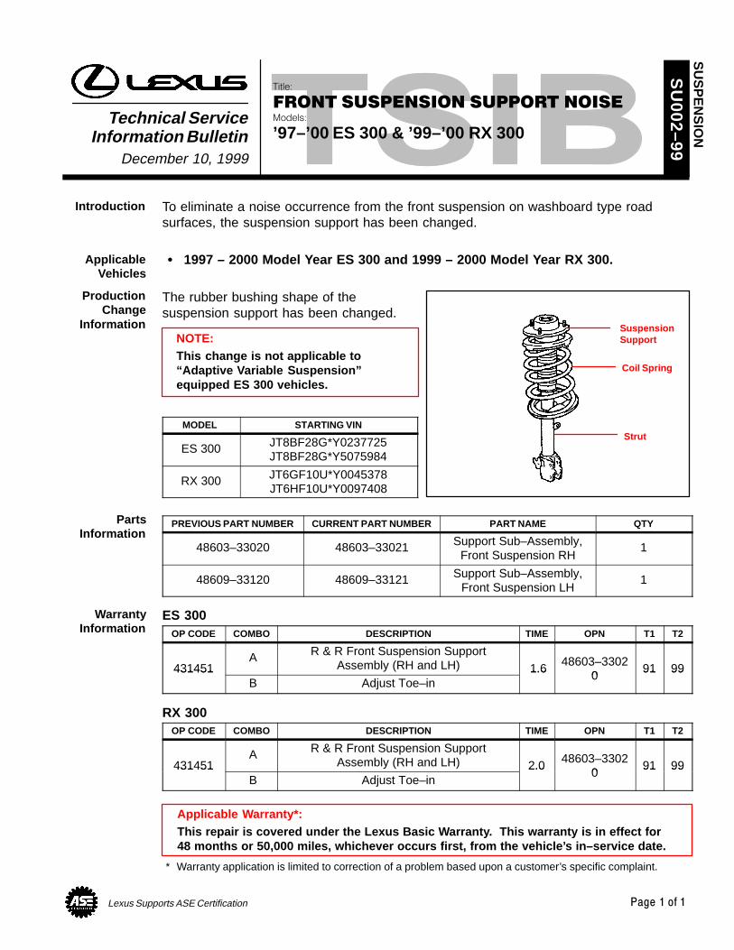
Lexus Supports ASE Certification Page 1 of 1
Title:
FRONT SUSPENSION SUPPORT NOISEModels:
’97–’00 ES 300 & ’99–’00 RX 300Technical Service
Information BulletinDecember 10, 1999
SU
002–99
To eliminate a noise occurrence from the front suspension on washboard type roadsurfaces, the suspension support has been changed.
1997 – 2000 Model Year ES 300 and 1999 – 2000 Model Year RX 300.
The rubber bushing shape of thesuspension support has been changed.
NOTE:This change is not applicable to“Adaptive Variable Suspension”equipped ES 300 vehicles.
MODEL STARTING VIN
ES 300 JT8BF28G*Y0237725JT8BF28G*Y5075984
RX 300 JT6GF10U*Y0045378JT6HF10U*Y0097408
PREVIOUS PART NUMBER CURRENT PART NUMBER PART NAME QTY
48603–33020 48603–33021 Support Sub–Assembly,Front Suspension RH
1
48609–33120 48609–33121 Support Sub–Assembly,Front Suspension LH
1
ES 300OP CODE COMBO DESCRIPTION TIME OPN T1 T2
431451 A R & R Front Suspension Support
Assembly (RH and LH) 1.6 48603–33020
91 99431451 B Adjust Toe–in
1.60
91 99
RX 300OP CODE COMBO DESCRIPTION TIME OPN T1 T2
431451 A R & R Front Suspension Support
Assembly (RH and LH) 2.0 48603–33020
91 99431451 B Adjust Toe–in
2.00
91 99
Applicable Warranty*:This repair is covered under the Lexus Basic Warranty. This warranty is in effect for48 months or 50,000 miles, whichever occurs first, from the vehicle’s in–service date.
* Warranty application is limited to correction of a problem based upon a customer’s specific complaint.
SU
SP
EN
SIO
N
Introduction
ApplicableVehicles
ProductionChange
Information SuspensionSupport
Coil Spring
Strut
PartsInformation
WarrantyInformation

Lexus Supports ASE Certification Page 1 of 1
Title:
REVISED DRIVE SHAFT GREASEModels:
LS 400, GS 300/400, SC 300/400, ES 250/300 &RX 300
Technical ServiceInformation Bulletin
April 9, 1999
TC
001–99
The greases supplied in replacement Inboard and Outboard Drive Shaft Boot Kits for thefollowing models, has been revised.
With this revision, the grease compositions have been changed and are now both thesame color . To correctly lubricate each joint, consult the Service Repair Manual as towhich size packet of grease is designated for each Drive Shaft Joint Assembly.
NOTE:Although Inboard and Outboard greases are now the same color, their compositionsare different.
All LS 400, GS 300/400, SC 300/400, ES 250/300 & RX 300 Models.
As outlined in the Service Repair Manual.
Refer to the appropriate Repair Manual for installation and lubrication information forDrive Shaft Joint Assemblies.
OPCODE DESCRIPTION TIME OPN T1 T2
N/A Not Applicable to Warranty – – – –
TR
AN
SM
ISS
ION
& C
LUT
CH
Introduction
AffectedVehicles
RequiredTools and
Material
RepairProcedure
WarrantyInformation

Lexus Supports ASE Certification Page 1 of 1
Title:
AUTOMATIC TRANSMISSION FLUID
TYPE T-IVModels:
All Models
Technical ServiceInformation Bulletin
June 19, 1998
TC
003–98
The introduction of Automatic Transmission Fluid type T–IV makes type T–II obsolete.Use type T–IV for all applications that specify ATF type T–II.
All vehicles with Automatic Transmissions specified to use ATF Types T–II or T–IV.
TYPE OF ATF
SPECIFIED ATF Dextron –III TYPE T TYPE T–II TYPE T–IV
Dextron –II or III OK X X XTYPE T X OK X X
TYPE T–II X X OK OKTYPE T–IV X X X OK
X = NOT USABLE
SIZE NEW PART NUMBER PART NAME
4 Liter 08886–01705 ATF type T–IV
OP CODE DESCRIPTION TIME OPN T1 T2
N/A Not Applicable to Warranty – – – –
TR
AN
SM
ISS
ION
& C
LUT
CH
Introduction
AffectedVehicles
PartsInformation
WarrantyInformation

Lexus Supports ASE Certification Page 1 of 1
Title:
AUTOMATIC TRANSMISSION FLUIDSModels:
All ModelsTechnical Service
Information BulletinSeptember 10, 1999
TC
003–99
REVISION NOTICE:The information contained in this TSIB updates TC003–98 dated June 19, 1998.
Automatic Transmission Fluid Type T–IV now replaces Type T–II fluid. Use Type T–IV forall applications that specify ATF Type T–II.
Please refer to the following table for the interchangeability between each ATF.
All vehicles produced after 1990 with Automatic Transmissions specified to useATF Type T, T–II and T–IV.
SPECIFIED ATFTYPE OF ATF
SPECIFIED ATFDEXRON® II OR III TYPE T TYPE T–II TYPE T–IV
DEXRON® II OR III OK X X X
TYPE T X OK X OK
TYPE T–II X X OK OK
TYPE T–IV X X X OK
X = NOT USABLE
NOTICE:With the exception of mixing ATF Type T with Type T–IV fluids, different types of fluidsmust not be mixed.
SIZE NEW PART NUMBER PART NAME
4 Liter 08886–01705 ATF Type T–IV
OPCODE DESCRIPTION TIME OPN T1 T2
N/A Not Applicable to Warranty – – – –
TR
AN
SM
ISS
ION
& C
LUT
CH
Introduction
ApplicableVehicles
PartsInformation
WarrantyInformation