titleblock and borders - world class cadworldclasscad.com/microstation_v8i_2d_pdf/ch09... · 2011....
TRANSCRIPT
9-1
C h a p t e r 9
Titleblock and Borders
This chapter will cover:
Designing a Titleblock Drawing a Titleblock Inserting the Titleblock Labels Cells Standard Architectural and Engineering Paper Sizes Creating an A Size Border Creating a B Size Border Creating a C Size Border Creating a D Size Border
9-2
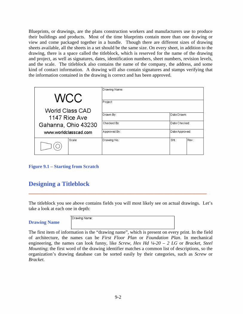
Blueprints, or drawings, are the plans construction workers and manufacturers use to produce their buildings and products. Most of the time blueprints contain more than one drawing or view and come packaged together in a bundle. Though there are different sizes of drawing sheets available, all the sheets in a set should be the same size. On every sheet, in addition to the drawing, there is a space called the titleblock, which is reserved for the name of the drawing and project, as well as signatures, dates, identification numbers, sheet numbers, revision levels, and the scale. The titleblock also contains the name of the company, the address, and some kind of contact information. A drawing will also contain signatures and stamps verifying that the information contained in the drawing is correct and has been approved.
Figure 9.1 – Starting from Scratch
Designing a Titleblock ________________________________________________________ The titleblock you see above contains fields you will most likely see on actual drawings. Let’s take a look at each one in depth:
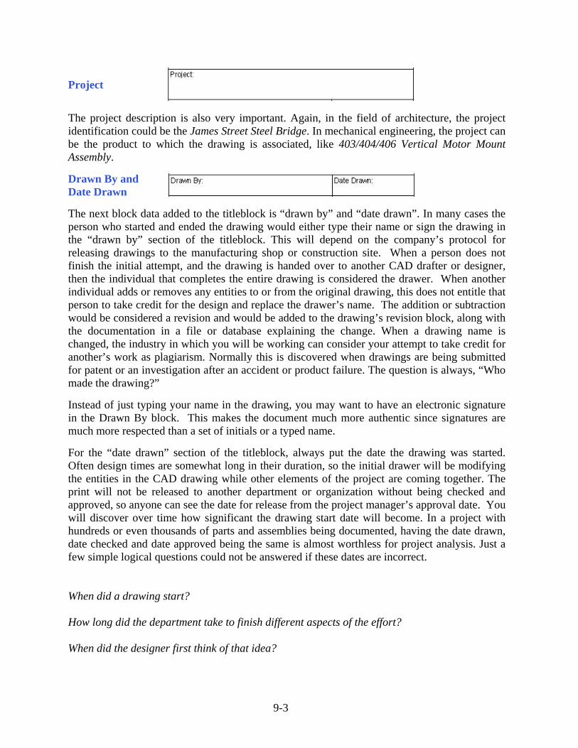
Drawing Name
The first item of information is the “drawing name”, which is present on every print. In the field of architecture, the names can be First Floor Plan or Foundation Plan. In mechanical engineering, the names can look funny, like Screw, Hex Hd ¼-20 – 2 LG or Bracket, Steel Mounting; the first word of the drawing identifier matches a common list of descriptions, so the organization’s drawing database can be sorted easily by their categories, such as Screw or Bracket.
9-3
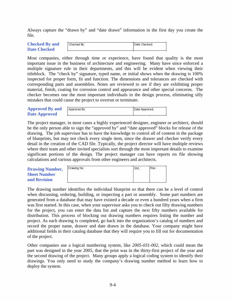
Project
The project description is also very important. Again, in the field of architecture, the project identification could be the James Street Steel Bridge. In mechanical engineering, the project can be the product to which the drawing is associated, like 403/404/406 Vertical Motor Mount Assembly. Drawn By and Date Drawn The next block data added to the titleblock is “drawn by” and “date drawn”. In many cases the person who started and ended the drawing would either type their name or sign the drawing in the “drawn by” section of the titleblock. This will depend on the company’s protocol for releasing drawings to the manufacturing shop or construction site. When a person does not finish the initial attempt, and the drawing is handed over to another CAD drafter or designer, then the individual that completes the entire drawing is considered the drawer. When another individual adds or removes any entities to or from the original drawing, this does not entitle that person to take credit for the design and replace the drawer’s name. The addition or subtraction would be considered a revision and would be added to the drawing’s revision block, along with the documentation in a file or database explaining the change. When a drawing name is changed, the industry in which you will be working can consider your attempt to take credit for another’s work as plagiarism. Normally this is discovered when drawings are being submitted for patent or an investigation after an accident or product failure. The question is always, “Who made the drawing?” Instead of just typing your name in the drawing, you may want to have an electronic signature in the Drawn By block. This makes the document much more authentic since signatures are much more respected than a set of initials or a typed name. For the “date drawn” section of the titleblock, always put the date the drawing was started. Often design times are somewhat long in their duration, so the initial drawer will be modifying the entities in the CAD drawing while other elements of the project are coming together. The print will not be released to another department or organization without being checked and approved, so anyone can see the date for release from the project manager’s approval date. You will discover over time how significant the drawing start date will become. In a project with hundreds or even thousands of parts and assemblies being documented, having the date drawn, date checked and date approved being the same is almost worthless for project analysis. Just a few simple logical questions could not be answered if these dates are incorrect. When did a drawing start? How long did the department take to finish different aspects of the effort? When did the designer first think of that idea?
9-4
Always capture the “drawn by” and “date drawn” information in the first day you create the file. Checked By and Date Checked Most companies, either through time or experience, have found that quality is the most important issue in the business of architecture and engineering. Many have since enforced a multiple signature rule in their departments, and this will be evident when viewing their titleblock. The “check by” signature, typed name, or initial shows when the drawing is 100% inspected for proper form, fit and function. The dimensions and tolerances are checked with corresponding parts and assemblies. Notes are reviewed to see if they are exhibiting proper material, finish, coating for corrosion control and appearance and other special concerns. The checker becomes one the most important individuals in the design process, eliminating silly mistakes that could cause the project to overrun or terminate.
Approved By and Date Approved The project manager, in most cases a highly experienced designer, engineer or architect, should be the only person able to sign the “approved by” and “date approved” blocks for release of the drawing. The job supervisor has to have the knowledge to control all of content in the package of blueprints, but may not check every single item, since the drawer and checker verify every detail in the creation of the CAD file. Typically, the project director will have multiple reviews where their team and other invited specialists sort through the most important details to examine significant portions of the design. The project manager can have reports on file showing calculations and various approvals from other engineers and architects.
Drawing Number, Sheet Number and Revision The drawing number identifies the individual blueprint so that there can be a level of control when discussing, ordering, building, or inspecting a part or assembly. Some part numbers are generated from a database that may have existed a decade or even a hundred years when a firm was first started. In this case, when your supervisor asks you to check out fifty drawing numbers for the project, you can enter the data list and capture the next fifty numbers available for distribution. This process of blocking out drawing numbers requires listing the number and project. As each drawing is completed, go back into the organization’s catalog of numbers and record the proper name, drawer and date drawn in the database. Your company might have additional fields in their catalog database that they will require you to fill out for documentation of the project. Other companies use a logical numbering system, like 2005-031-002, which could mean the part was designed in the year 2005, that the print was in the thirty-first project of the year and the second drawing of the project. Many groups apply a logical coding system to identify their drawings. You only need to study the company’s drawing number method to learn how to deploy the system.
9-5
The block containing the sheet number may be blank or hold a “1” for the first sheet of the group of drawings holding the same drawing number. When an architect completes a package for a residential home with 25 drawings, each print has the same drawing number and has a label with their own sheet number, i.e., 1, 2, 3, 4, progressing all the way to 25. Some companies will show the text Sheet 1 of 25, but this is not a necessary label for every page, since an additional print in the set will cause a CAD operator to change all the numbers from 25 to 26. To make things easier, just add the additional reference to the package’s title print, which is usually the first print, showing the sheet number and name.
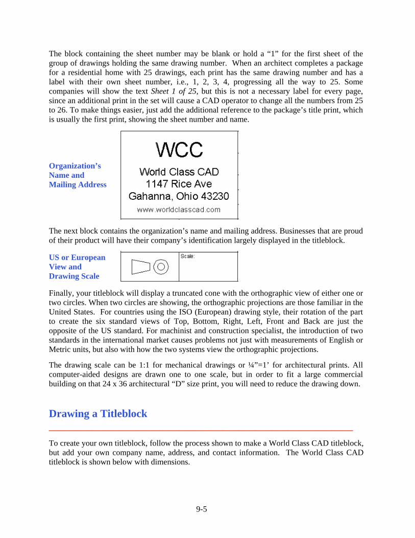
Organization’s Name and Mailing Address
The next block contains the organization’s name and mailing address. Businesses that are proud of their product will have their company’s identification largely displayed in the titleblock.
US or European View and Drawing Scale Finally, your titleblock will display a truncated cone with the orthographic view of either one or two circles. When two circles are showing, the orthographic projections are those familiar in the United States. For countries using the ISO (European) drawing style, their rotation of the part to create the six standard views of Top, Bottom, Right, Left, Front and Back are just the opposite of the US standard. For machinist and construction specialist, the introduction of two standards in the international market causes problems not just with measurements of English or Metric units, but also with how the two systems view the orthographic projections. The drawing scale can be 1:1 for mechanical drawings or ¼”=1’ for architectural prints. All computer-aided designs are drawn one to one scale, but in order to fit a large commercial building on that 24 x 36 architectural “D” size print, you will need to reduce the drawing down.
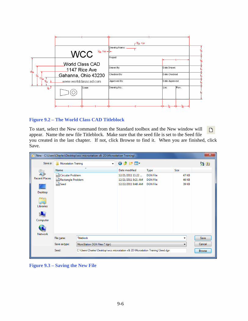
Drawing a Titleblock ________________________________________________________ To create your own titleblock, follow the process shown to make a World Class CAD titleblock, but add your own company name, address, and contact information. The World Class CAD titleblock is shown below with dimensions.
9-6
Figure 9.2 – The World Class CAD Titleblock To start, select the New command from the Standard toolbox and the New window will appear. Name the new file Titleblock. Make sure that the seed file is set to the Seed file
you created in the last chapter. If not, click Browse to find it. When you are finished, click Save.
Figure 9.3 – Saving the New File
9-7
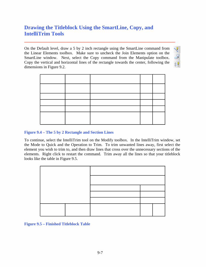
Drawing the Titleblock Using the SmartLine, Copy, and IntelliTrim Tools ________________________________________________________ On the Default level, draw a 5 by 2 inch rectangle using the SmartLine command from the Linear Elements toolbox. Make sure to uncheck the Join Elements option on the SmartLine window. Next, select the Copy command from the Manipulate toolbox. Copy the vertical and horizontal lines of the rectangle towards the center, following the dimensions in Figure 9.2.
Figure 9.4 – The 5 by 2 Rectangle and Section Lines To continue, select the IntelliTrim tool on the Modify toolbox. In the IntelliTrim window, set the Mode to Quick and the Operation to Trim. To trim unwanted lines away, first select the element you wish to trim to, and then draw lines that cross over the unnecessary sections of the elements. Right click to restart the command. Trim away all the lines so that your titleblock looks like the table in Figure 9.5.
Figure 9.5 – Finished Titleblock Table
9-8
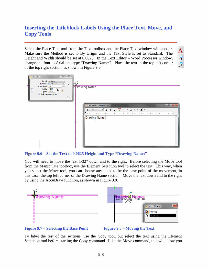
Inserting the Titleblock Labels Using the Place Text, Move, and Copy Tools ________________________________________________________ Select the Place Text tool from the Text toolbox and the Place Text window will appear. Make sure the Method is set to By Origin and the Text Style is set to Standard. The Height and Width should be set at 0.0625. In the Text Editor – Word Processor window, change the font to Arial and type “Drawing Name:”. Place the text in the top left corner of the top right section, as shown in Figure 9.6.
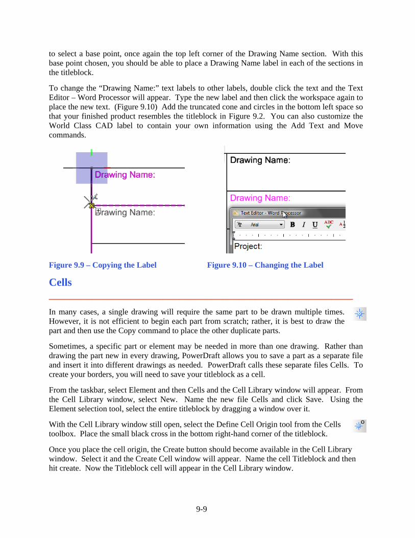
Figure 9.6 – Set the Text to 0.0625 Height and Type “Drawing Name:” You will need to move the text 1/32” down and to the right. Before selecting the Move tool from the Manipulate toolbox, use the Element Selection tool to select the text. This way, when you select the Move tool, you can choose any point to be the base point of the movement, in this case, the top left corner of the Drawing Name section. Move the text down and to the right by using the AccuDraw function, as shown in Figure 9.8.
Figure 9.7 – Selecting the Base Point Figure 9.8 – Moving the Text To label the rest of the sections, use the Copy tool, but select the text using the Element Selection tool before starting the Copy command. Like the Move command, this will allow you
9-9
to select a base point, once again the top left corner of the Drawing Name section. With this base point chosen, you should be able to place a Drawing Name label in each of the sections in the titleblock. To change the “Drawing Name:” text labels to other labels, double click the text and the Text Editor – Word Processor will appear. Type the new label and then click the workspace again to place the new text. (Figure 9.10) Add the truncated cone and circles in the bottom left space so that your finished product resembles the titleblock in Figure 9.2. You can also customize the World Class CAD label to contain your own information using the Add Text and Move commands.
Figure 9.9 – Copying the Label Figure 9.10 – Changing the Label
Cells ________________________________________________________ In many cases, a single drawing will require the same part to be drawn multiple times. However, it is not efficient to begin each part from scratch; rather, it is best to draw the part and then use the Copy command to place the other duplicate parts.
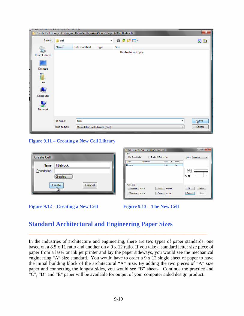
Sometimes, a specific part or element may be needed in more than one drawing. Rather than drawing the part new in every drawing, PowerDraft allows you to save a part as a separate file and insert it into different drawings as needed. PowerDraft calls these separate files Cells. To create your borders, you will need to save your titleblock as a cell. From the taskbar, select Element and then Cells and the Cell Library window will appear. From the Cell Library window, select New. Name the new file Cells and click Save. Using the Element selection tool, select the entire titleblock by dragging a window over it. With the Cell Library window still open, select the Define Cell Origin tool from the Cells toolbox. Place the small black cross in the bottom right-hand corner of the titleblock. Once you place the cell origin, the Create button should become available in the Cell Library window. Select it and the Create Cell window will appear. Name the cell Titleblock and then hit create. Now the Titleblock cell will appear in the Cell Library window.
9-10
Figure 9.11 – Creating a New Cell Library
Figure 9.12 – Creating a New Cell Figure 9.13 – The New Cell
Standard Architectural and Engineering Paper Sizes ________________________________________________________ In the industries of architecture and engineering, there are two types of paper standards: one based on a 8.5 x 11 ratio and another on a 9 x 12 ratio. If you take a standard letter size piece of paper from a laser or ink jet printer and lay the paper sideways, you would see the mechanical engineering “A” size standard. You would have to order a 9 x 12 single sheet of paper to have the initial building block of the architectural “A” Size. By adding the two pieces of “A” size paper and connecting the longest sides, you would see “B” sheets. Continue the practice and “C”, “D” and “E” paper will be available for output of your computer aided design product.
9-11
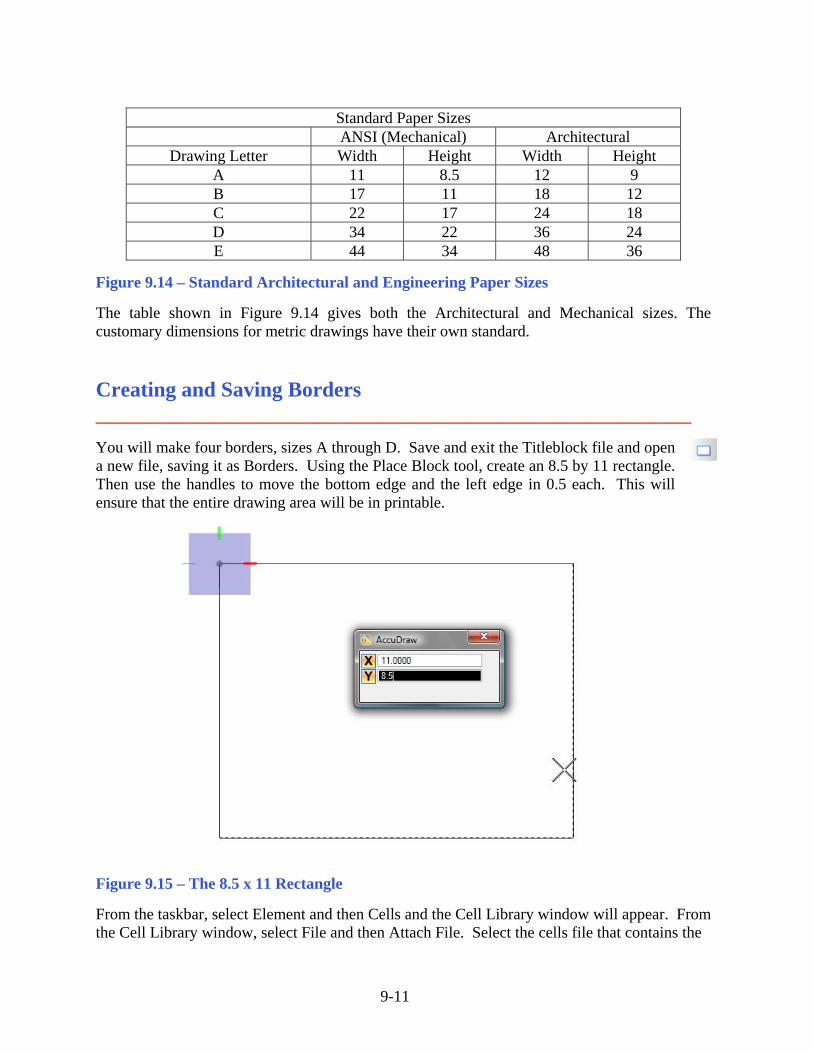
Standard Paper Sizes ANSI (Mechanical) Architectural
Drawing Letter Width Height Width Height A 11 8.5 12 9 B 17 11 18 12 C 22 17 24 18 D 34 22 36 24 E 44 34 48 36
Figure 9.14 – Standard Architectural and Engineering Paper Sizes The table shown in Figure 9.14 gives both the Architectural and Mechanical sizes. The customary dimensions for metric drawings have their own standard.
Creating and Saving Borders ________________________________________________________ You will make four borders, sizes A through D. Save and exit the Titleblock file and open a new file, saving it as Borders. Using the Place Block tool, create an 8.5 by 11 rectangle. Then use the handles to move the bottom edge and the left edge in 0.5 each. This will ensure that the entire drawing area will be in printable.
Figure 9.15 – The 8.5 x 11 Rectangle From the taskbar, select Element and then Cells and the Cell Library window will appear. From the Cell Library window, select File and then Attach File. Select the cells file that contains the
9-12
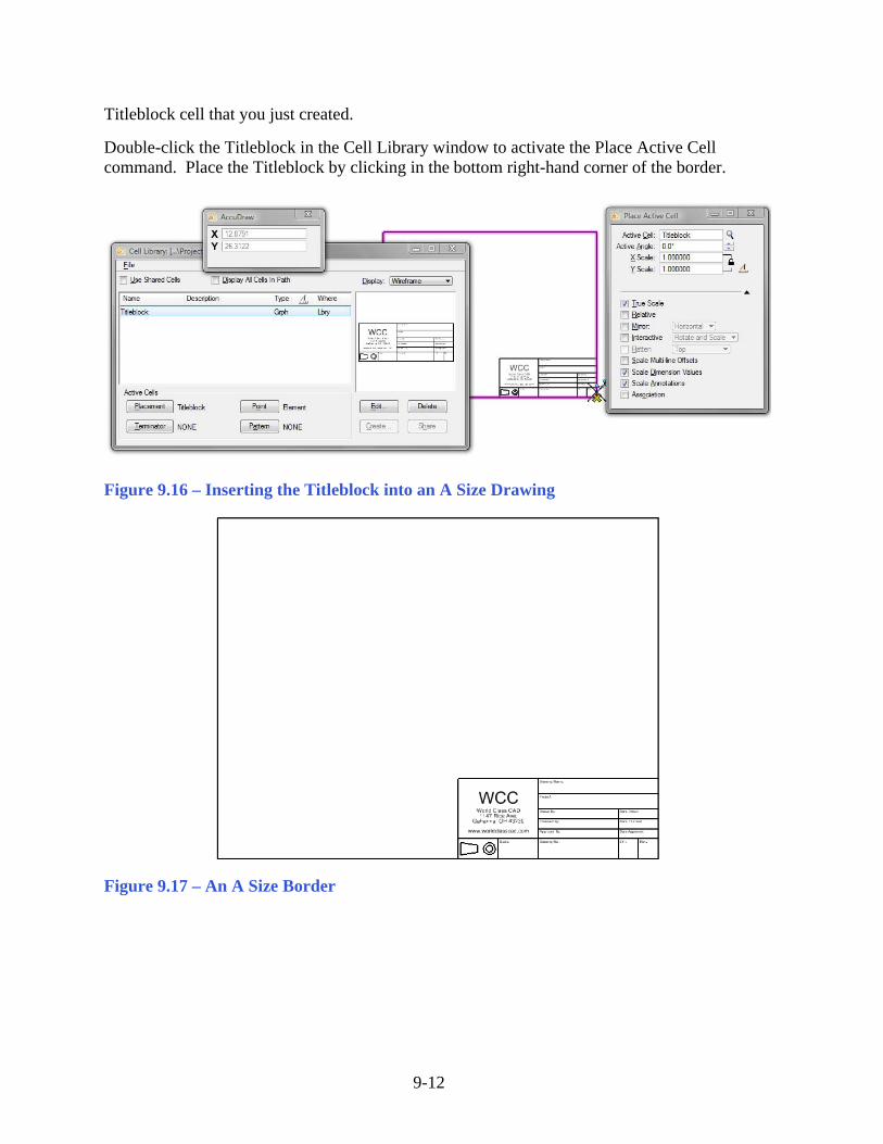
Titleblock cell that you just created. Double-click the Titleblock in the Cell Library window to activate the Place Active Cell command. Place the Titleblock by clicking in the bottom right-hand corner of the border.
Figure 9.16 – Inserting the Titleblock into an A Size Drawing
Figure 9.17 – An A Size Border
9-13
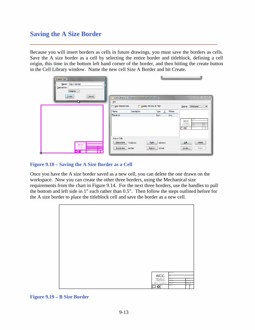
Saving the A Size Border ________________________________________________________ Because you will insert borders as cells in future drawings, you must save the borders as cells. Save the A size border as a cell by selecting the entire border and titleblock, defining a cell origin, this time in the bottom left hand corner of the border, and then hitting the create button in the Cell Library window. Name the new cell Size A Border and hit Create.
Figure 9.18 – Saving the A Size Border as a Cell Once you have the A size border saved as a new cell, you can delete the one drawn on the workspace. Now you can create the other three borders, using the Mechanical size requirements from the chart in Figure 9.14. For the next three borders, use the handles to pull the bottom and left side in 1” each rather than 0.5”. Then follow the steps outlined before for the A size border to place the titleblock cell and save the border as a new cell.
Figure 9.19 – B Size Border
9-14
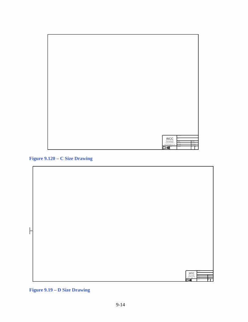
Figure 9.120 – C Size Drawing
Figure 9.19 – D Size Drawing
9-15
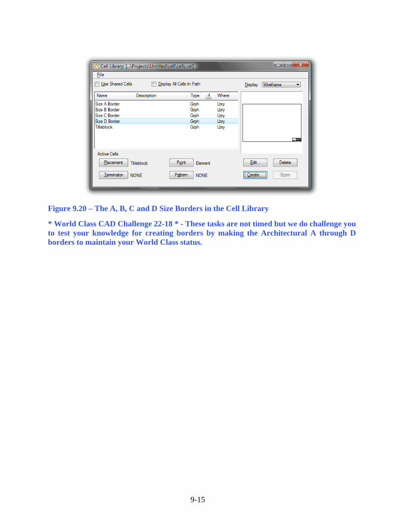
Figure 9.20 – The A, B, C and D Size Borders in the Cell Library * World Class CAD Challenge 22-18 * - These tasks are not timed but we do challenge you to test your knowledge for creating borders by making the Architectural A through D borders to maintain your World Class status.