tlab solve net challenges with optical lan an
TRANSCRIPT
8/10/2019 Tlab Solve Net Challenges With Optical Lan An
http://slidepdf.com/reader/full/tlab-solve-net-challenges-with-optical-lan-an 1/5
See tellabs.com for more information about Tellabs Solutions
How Enterprises Are Solving Evolving Network Challenges
with Passive Optical LAN
WHITE PAPER
Executive SummaryEnterprise businesses that need to upgrade or replace existing
telecommunications networks are looking for ways to improve energy
efficiency and reduce capital and operating expenses. Technology
managers are looking for solutions that furnish high bandwidth while
increasing the security and reliability of their networks.
To meet these requirements, enterprises are turning to Gigabit
Passive Optical Networks (GPON) Optical LANs. Passive Optical
LANs provide enormous value to enterprises without forcing them to
alter how they do business, while existing services provided by theirnetworks remain the same with no change to core and user devices.
Additionally, enterprises are saving up to 30%–50% of capital costs,
50%–70% of on-going operational costs, 30%–65% on energy
and 90% of the rack space while exceeding their environmental
sustainability goals. Plus, businesses deploying Passive Optical
LANs experience long-term savings by future-proofing their network
infrastructure while realizing all of the benefits of converging
their networked services, including voice, video, wireless access,
security, surveillance, building environmental controls and building
automation with Power over Ethernet (PoE) where needed.
This white paper explains how Passive Optical LANs work and how
they can benefit your organization. It also highlights why enterprisesare looking to deploy Passive Optical LANs solutions that are
environmentally responsible and solve evolving network challenges
while significantly cutting CapEx and OpEx, energy consumption and
space requirements.
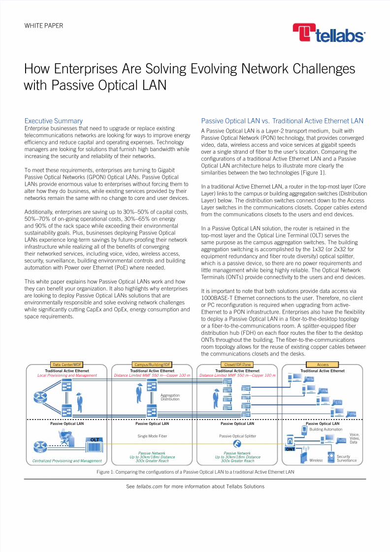
Passive Optical LAN vs. Traditional Active Ethernet LAN
A Passive Optical LAN is a Layer-2 transport medium, built with
Passive Optical Network (PON) technology, that provides converged
video, data, wireless access and voice services at gigabit speeds
over a single strand of fiber to the user’s location. Comparing the
configurations of a traditional Active Ethernet LAN and a Passive
Optical LAN architecture helps to illustrate more clearly the
similarities between the two technologies [Figure 1].
In a traditional Active Ethernet LAN, a router in the top-most layer (Core
Layer) links to the campus or building aggregation switches (DistributionLayer) below. The distribution switches connect down to the Access
Layer switches in the communications closets. Copper cables extend
from the communications closets to the users and end devices.
In a Passive Optical LAN solution, the router is retained in the
top-most layer and the Optical Line Terminal (OLT) serves the
same purpose as the campus aggregation switches. The building
aggregation switching is accomplished by the 1x32 (or 2x32 for
equipment redundancy and fiber route diversity) optical splitter,
which is a passive device, so there are no power requirements and
little management while being highly reliable. The Optical Network
Terminals (ONTs) provide connectivity to the users and end devices.
It is important to note that both solutions provide data access via1000BASE-T Ethernet connections to the user. Therefore, no client
or PC reconfiguration is required when upgrading from active-
Ethernet to a PON infrastructure. Enterprises also have the flexibility
to deploy a Passive Optical LAN in a fiber-to-the-desktop topology
or a fiber-to-the-communications room. A splitter-equipped fiber
distribution hub (FDH) on each floor routes the fiber to the desktop
ONTs throughout the building. The fiber-to-the-communications
room topology allows for the reuse of existing copper cables between
the communications closets and the desks.
Data Center/MDF Campus/Building/IDF Closet/IDF/Zone Access
OLT
Traditional Active Ethernet Traditional Active Ethernet Traditional Active Ethernet Traditional Active EthernetLocal Provisioning and Management
Centralized Provisioning and Management
Distance Limited MMF 550 m—Copper 100 m
Passive NetworkUp to 30km/18mi Distance
300x Greater Reach
Passive NetworkUp to 30km/18mi Distance
300x Greater Reach
Distance Limited MMF 550 m—Copper 100 m
Passive Optical LAN Passive Optical LAN Passive Optical LAN Passive Optical LAN
AggregationDistribution
Building Automation
Passive Optical SplitterSingle Mode Fiber Voice,Video,Data
SecuritySurveillanceWireless
ONT
Figure 1: Comparing the configurations of a Passive Optical LAN to a t raditional Active Ethernet LAN

8/10/2019 Tlab Solve Net Challenges With Optical Lan An
http://slidepdf.com/reader/full/tlab-solve-net-challenges-with-optical-lan-an 2/5
2 HOW ENTERPRISES ARE SOLVING EVOLVING NETWORK CHALLENGES WITH PASSIVE OPTICAL LAN
See tellabs.com for more information about Tellabs Solutions
A Passive Optical LAN’s ONT has all of the required Layer-2
functionality built in. The Passive Optical LAN provides integrated
Ethernet bridging, VLAN capability required for network
segmentation, and user authentication and security filtering.
The ONT, which functions much like an Ethernet switch, makesit possible for an enterprise to seamlessly replace an Ethernet-
switched LAN.
Deliver Significant CapEx and OpEx Savings
When upgrading your network infrastructure, it is important to look
at both the near-term and long-term expenses. Today’s enterprise
requires solutions that not only lower initial capital expenses, but
also reduce the total cost of ownership (TCO) for the network.
Forward-looking managers insist that new systems address more of
their telecommunications requirements while minimizing ongoing
operational expenses.
Passive Optical LAN technology enables the enterprise tosignificantly reduce the cabling infrastructure costs from the data
center to the user by significantly reducing the number of cable
runs. The result is a decrease in overall operational costs and
network complexity.
Each ONT model supports multiple densities of Gigabit Ethernet,
POTS and RF video. This integrated approach provides the ability to
connect building automation systems, security cameras and building
sensors all on the same infrastructure, thereby removing the
requirement and expense of separate transport systems across the
campus for each technology. The PON infrastructure also eliminates
costly hardware within a network, such as remote switches, as well
as their associated provisioning cost, annual maintenance and
software licensing fees.
A Passive Optical LAN extends the network life cycle to 10 years or
more. This approach enables:
n Gradual, more predictable costs for bandwidth upgrades over
the full 10-year period
n Modest ongoing maintenance costs associated with fiber
n Seamless addition of more technology-based capabilities, such
as wave-division multiplexing 40- and 100-Gbps transport and
terabyte switching
Developed for low-cost fiber-based converged network service
delivery, GPON standards were finalized by the ITU in 2003 (ITU
G984.x). Tellabs first publicly demonstrated standards-based GPON
OLTs and ONTs to the North American service provider consortium
led by Verizon, AT&T and BellSouth in May 2006. Today, the growing
market acceptance reflects Passive Optical LAN’s ability to support
critical enterprise applications with greater efficiency than traditional
Active Ethernet.
Passive Optical LAN attains up to 95% bandwidth utilization efficiency,
whereas traditional Active Ethernet suffers from efficiency rates as
low as 69%. Coupled with strong encryption support, Passive Optical
LAN delivers the most efficient and secure technology available.
Lower Space Requirements
Cutting back on floor, rack and closet space is also extremely
important to organizations looking to save. Reduction in floor space
lowers operating expenses by reducing overhead costs, such asspace and HVAC. In addition, the smaller footprint associated
with Passive Optical LAN technology enables next-generation
performance and services in smaller communication closets not
originally designed for advanced communications equipment.
A typical active-Ethernet LAN serving up to 2,016 users requires 90
rack units of space. Active-Ethernet LAN switches require one full
rack for the switches and two additional racks for terminating the
large bundles of copper cables associated with the switches. The total
solution would require a total of 18 seven-foot-tall equipment racks.
Comparatively, a Passive Optical LAN serves up to 7,700 users.
Due to the OLT’s 90% greater density, this solution requires only 1
equipment rack and a total of 9 rack units within the rack.
Additionally, a Passive Optical LAN requires fewer communications
closets and, in some cases, eliminates them altogether. As a result,
a business can recover physical space and cut expenses. The
single-mode fiber in the Passive Optical LAN, however, can reach up
to 30 kilometers. This enables an enterprise to:
n Reduce or eliminate repeaters, switches and
communications closets
n Deploy an OLT in a single central location
Meet Green Sustainability Objectives
Passive Optical LAN offers power savings of up to 30%–65% over
active-Ethernet solutions supporting green initiatives and reducing
total cost of ownership. It is a passive architecture, therefore it
requires no power within the Optical Distribution Network (ODN)
also known as the outside cable plant, which removes all power
requirements from the building aggregation portion of the network.
Not only does less equipment require less power, but it also has a
ripple effect on many other areas, including power distribution and
switchgear, power conversion and air conditioning cooling. One in
five companies now has a dedicated budget allocated for green IT
initiatives, and 44 percent say that they are moving toward doing so.
Deploy a Future-Proof Infrastructure
Installing a single-mode fiber (SMF) infrastructure virtually future-
proofs your network. Since SMF has been demonstrated to carry101 Tbps of full duplex bandwidth, the next-generation network
upgrade will not impact the installed fiber distribution network, and
you will only need to upgrade the electronics. Utilizing SMF extends
the LAN reach out to 30 kilometers without signal regeneration.
Typically, the cable plant is the most expensive part of a technology
upgrade. Installing SMF removes the requirement for additional
upgrades to your cable plant in the foreseeable future. Additionally,
recent advances in fiber connector technology have reduced the cost
of installing fiber significantly, and in most cases the installation of fiber
is now less labor intensive than installation of a copper cable plant.

8/10/2019 Tlab Solve Net Challenges With Optical Lan An
http://slidepdf.com/reader/full/tlab-solve-net-challenges-with-optical-lan-an 3/5
3 HOW ENTERPRISES ARE SOLVING EVOLVING NETWORK CHALLENGES WITH PASSIVE OPTICAL LAN
See tellabs.com for more information about Tellabs Solutions
Finally, in a direct comparison to CATx copper cable plant, SMF
is smaller, lighter and stronger; has a tighter bend radius, higher
bandwidth capacity and longer reach; is less susceptible to EMI
interference; has faster connector solutions and longer life; and
entails less material expense than CATx.
Converge All Services
Converging all network services is the foremost feature of the
Passive Optical LAN. It will converge all services across a single
infrastructure, eliminating the need for multiple platforms while
providing highly scalable high-speed data services to all users.
Additionally, voice (e.g., analog POTS and VoIP w/PoE), video, video
conferencing services, wireless access and monitoring services
(e.g., building automation system, security cameras and building
sensors) are all supported on the Passive Optical LAN.
Voice — Providing the same services as a legacy switching
architecture, VoIP handsets are connected at the Optical NetworkTerminals (ONT) via a standard RJ-45 gigabit Ethernet port. The
VoIP service is transported to IP PBX or softswitch as standard
IP/Ethernet traffic [Figure 2].
Figure 2: VoIP over Optical LAN architecture
Passive Optical LAN Optical Line Terminals (OLT) and ONTs can
also support analog voice, or what is commonly called Plain Old
Telephone Service (POTS). In this scenario, the ONT itself contains
a Session Initiation Protocol (SIP) to the analog converter that allows
the POTS phone to plug into a RJ-11 port on the ONT [Figure 3].
As the ONT converts the POTS call to SIP, it is transported over the
Passive Optical LAN system in a VoIP format, which is handled in
one of two ways. The first option is to convert the call back to analog
with a voice gateway (VGW) that provides legacy PBX integration or
tip/ring lines from the carrier. The second approach ties the POTS
phone as a SIP call directly to a VoIP extension on the customer’s
IP-PBX or softswitch, eliminating the need for VoIP phones to bepurchased. Both options provide full integration with the features of
the legacy TDM PBX, POTS lines or the VoIP softswitch, and deliver
call waiting, message waiting indicator lights, voicemail and all other
features to the user via the analog POTS handset.
The ONTs do support IEEE standards for IEEE 802.3af PoE (15.4
watts at an Ethernet port) and IEEE 802.3at PoE+ (25.6 watts at an
Ethernet port) to power the VoIP handsets.
Figure 3: Analog (POTS) over Optical LAN architecture
Regardless of the solution being deployed (VoIP or POTS services), the
Passive Optical LAN system provides the necessary network protocols
and quality of service (QoS) required in the modern enterprise
environment. This allows for VLAN trunking and creating “daisy
chained” PCs fed off of the VoIP endpoint with a separate VLAN andQoS settings for each achieved via standards based on IEEE 802.1q
and DSCP mappings that guarantee that the voice calls are clear.
Video — Since Passive Optical LAN is a standard transport system,
IP video content can be deployed with little effort. As an example,
small enterprises are able to encode off-air analog and digital
channels, and deliver them in both standard definition and high
definition quality [Figure 4]. These video networks are built to suppor
local cached content for video on demand (VoD) and other interactive
services. There are even options for local content insertion (e.g.,
facility news, company news and training). This is accomplished
over the Passive Optical LAN equipment, since the video is once
again transported in an IP/Ethernet format. As the Passive Optical
LAN system leverages Internet Group Management Protocol (IGMP)multicast delivery mechanisms, it is a highly efficient means to delive
video on the network. IGMP multicasting takes place across the
OLT and ONTs so as to ensure that only a single copy of the unique
IP video stream is efficiently sent across the network, optimizing
bandwidth. This same architecture can support enterprise-centric IP
video, such as video conferencing (VTC), telepresence conferencing,
telepresence robots and video surveillance.
Figure 4: IP video over Optical LAN architecture
Access
Softswitch
or
IP PBX
GbE OLTGPONDS 1490 nm
US 1310 nm ODNSplitter
RJ-45
RJ-45RJ-45
DataVoiceVoIPRJ-45
Video
Data Center/MDF Closet/IDF/Zone
ONT
Access
VGW
Voice
Switch
GbE
GPONDS 1490 nm
US 1310 nm ODNSplitter
Twisted pairvia RJ-11
Data
CATx viaRJ-45
Voice
RF or IPVideo
Data Center /MDF C lose t/ IDF/Zone
1000
PSTN GbE
DS1
OLT
ONT
Access
GbE
GPONDS 1490 nm
US 1310 nm ODNSplitter
Video
Conference
CATx viaRJ-45
IP video
Surveillance
IP Video
with VOD
Data Center/MDF Closet/IDF/Zone
MiddlewareServer
Videoon DemandCachedcontent
Encoders
Ethernet OLT
ONT

8/10/2019 Tlab Solve Net Challenges With Optical Lan An
http://slidepdf.com/reader/full/tlab-solve-net-challenges-with-optical-lan-an 4/5
4 HOW ENTERPRISES ARE SOLVING EVOLVING NETWORK CHALLENGES WITH PASSIVE OPTICAL LAN
See tellabs.com for more information about Tellabs Solutions
Identical to voice services on the Passive Optical LAN, strict QoS
preserves the video content and priority in the network. This is
especially critical in video conferencing (VTC) and in telepresence
applications. The video is delivered through rate limiting (shaping),
queue management (buffering) and scheduling (policing)mechanisms. The bandwidth rate limiting is set by provisioning the
sustained data rate levels and burst or peak rate for proper traffic
shaping. Finally, the OLT and ONT queue (buffers) and scheduling
(policing) smooths any bursty traffic. All of the above together builds
your service level agreements (SLA) that ensure that the IP video
quality is high and the user experience is superior.
If there is RF video, Passive Optical LAN provides video overlay
service in compliance with ITU-T G.984. The RF video is carried
on the system using a third wavelength (1550 nm) [Figure 5].
The video signal format delivered to the customer is defined by
SCTE standards. From the ONT, a standard 750 ohm coaxial
interface supports 54–900 MHz CATV channel content. Since this
is accomplished over a separate wavelength, the RF video network
equipment is not aware of the Passive Optical LAN presence. With
the centralized management of the Passive Optical LAN, the coaxial
output can be tuned to match the signal levels required for the
customers remotely and allow for remote balancing of the network.
Figure 5: RF video over Optical LAN architecture
Wireless — Passive Optical LAN also be used to wireless
backhaul transport of the access points traffic. It can do so in
two architectures. First, there is the stand-alone static Wi-Fi
architecture with no robust controller functionality. In this scenario,
Passive Optical LAN can provide the benefits of lower equipment
cost, reduced energy and collapsed cabling infrastructure. There
are also wireless access point (WAP) features and functionality
integration that can be accomplished with Passive Optical LANvia the centralized management platform. Passive Optical LAN
provides a greater system reach for improved performance and
coverage for Wi-Fi service. As Passive Optical LAN interoperates with
established Wi-Fi vendors, it allows for Wi-Fi controller functionality
to be provided by best-of-breed Wi-Fi manufacturers without limiting
the customer’s options [Figure 6]. The controller functionality adds
dynamic provisioning, interference correction, load balancing and
coverage optimization as is required in a true enterprise deployment.
Today, there is Passive Optical LAN deployment with industry
leaders like Cisco, Aruba, Ruckus and Meru.
Figure 6: Wi-Fi over Optical LAN architecture
There are also synergies between distributed antenna systems (DAS
and Passive Optical LAN. To be clear, the DAS traffic does NOT
traverse the Passive Optical LAN equipment, but it can leverage the
same fiber infrastructure that Passive Optical LAN utilizes [Figure 7]
Alone, DAS has a challenging return-on-investment analysis — it is
relatively expensive; it only does one thing; and the end customers
think they should not have to pay for it. Passive Optical LAN has an
excellent ROI that can justify the deployment of DAS over existing
spare fibers. In the near term, DAS and Passive Optical LAN can
gain additional synergies with combined powering, power backup
and fiber management between them. In the future as both DAS
and Passive Optical LAN technologies advance, it can be expected
that the Passive Optical LAN ONT can integrate both DAS antenna
and Wi-Fi WAP hardware.
Figure 7: DAS over fiber with synergies with Optical LAN architecture
Once again, it should be noted that the ONTs do support IEEE
standards for IEEE 802.3af PoE and IEEE 802.3at PoE+ to
power the Wi-Fi WAPs. These ONTs provide powered device (PD)
management, monitoring and configuration using LLDP. Thus,
the ONT detects the actual power requirements of a PD and then
adjusts the power allocation for that PoE port. There are also
mechanisms for providing reports on power consumption so that IT
managers can adjust deployment configurations to low-power modes
for devices like WAPs and IP phones alike.
AccessData Center /MDF C lose t/ IDF/Zone
FiberManagement
OLAN OLT
Core Switch
Wi-FiControllerVendor X
WAPVendor X
CATxPoE+
OLT
HybridSMFCable(option)
FiberManagementandPowerManagement
ONT
AccessData Center /MDF C loset/ IDF/Zone
FiberManagement
DASHeadend
Equipment
OLAN OLT
Core Switch
Wi-FiController
CATxPoE+
DASRemote
OLT
WAPVendor X
SMF(DAS)
SMF(DAS)
SMF
(GPON)
SMF(GPON)
Fiber
Management
ONT
Access
GPON oversingle mode fiber
DS 1490 nm
US 1310 nmODN
Splitter
CATx viaRJ-45
Coax viaF-Connector
Voice
Data Center /MDF C lose t/ IDF/Zone
RF Video
No VOD
No interactive
services
Data
OTT content
Twisted pairvia RJ-11
1550 nm
54–870 MHz
TransmitterEDFA
CATVHeadend
CWDM
Coupler/ Combiner
OLT
ONT

8/10/2019 Tlab Solve Net Challenges With Optical Lan An
http://slidepdf.com/reader/full/tlab-solve-net-challenges-with-optical-lan-an 5/5
5 HOW ENTERPRISES ARE SOLVING EVOLVING NETWORK CHALLENGES WITH PASSIVE OPTICAL LAN
Latin America & Caribbean
TellabsRua James Joule No. 92EDIFÍCIO PLAZA ISão Paulo – SP04576-080Brasil+55 11 3572 6200Fax: +55 11 3572 6225
North America
Tellabs1415 West Diehl RoadNaperville, IL 60563U.S.A.+1 630 798 8800Fax: +1 630 798 2000
Asia Pacific
Tellabs350 Orchard Road#18–01 Shaw HouseSingapore 238868Republic of Singapore+65 6572 5600Fax: +65 6572 5601
Europe, Middle East & Africa
TellabsSuites 1 & 2St Johns CourtEaston StreetHigh Wycombe, BucksHP11 1JXUnited Kingdom+44 871 574 7000Fax: +44 871 574 7151
The following trademarks and service marks are owned by Tellabs Operations, Inc., or its affiliates in the United States and/or in other countries: TELLABS®, TELLABS and T symbol®, T symbol® , and SMARTCORE®. Statements herein may contain
projections or other forward-looking statements regarding future events, products, features, technology and resulting commercial or technological benefits and advantages. These statements are for discussion purposes only, are subject to change and are
not to be construed as instructions, product specifications, guarantees or warranties. Actual results may differ materially. The information contained herein is not a commitment, promise or legal obligation to deliver any material, code, feature or functionalit
It is intended to outline Tellabs’ general product direction. The development, release and timing of any material, code, feature or functionality described herein remains at Tellabs’ sole discretion.
© 2014 Tellabs. All rights reserved.
Smart/Intelligent Buildings — A Building Management System (BMS)
and Building Automation System (BAS) are extremely important for
any new high-performance buildings and a key to reducing operating
costs. Building monitoring devices and system reporting and analysis
tools require IP/Ethernet connectivity. In recent years, the Passive
Optical LAN has taken on the responsibility to integrate thesefunctions. Since the majority of BMS/BAS monitoring devices today
are IP/Ethernet based, the connectivity into the existing (or new)
Passive Optical LAN is seamless [Figure 7]. The Passive Optical LAN
can ensure adequate bandwidth, security, authentication and quality
of service specific to each monitoring and management device.
Smooth Upgrade Path to Next-Generation Services
Passive Optical LAN supports legacy voice, including Session
Initiation Protocol (SIP); video, including IPTV and RF over Glass
(RFoG); high-speed data; and business services. The ITU created
the GPON standard with the ability to support multiple services, and
Passive Optical LAN takes advantage of this capability by providing a
smooth upgrade path from existing to next-generation services. ThePassive Optical LAN easily scales as the campus network expands
and evolves, providing a simple and cost-effective migration path.
To understand how it works, see Figure 3. Figure 3 is a network
diagram of a typical VoIP installation. On the left is the router, voice
Gateway and either an IP-enabled PBX or a softswitch. The network
is then connected to the Tellabs OLT in the center (Distribution Area)
of the network. A PON port on the OLT is then connected to the
splitter that feeds a series of ONTs in either the closet or work area.
The Ethernet ports on the ONTs are then connected to either a PC
or VoIP telephone instrument. Enterprises also have the option to
connect POTS analog telephone sets to selected ONT ports.
Improve Security and ReliabilityPassive Optical LAN is highly secure and produces none of the EMI
radiation that is typically associated with traditional copper-wired
facilities. Utilizing fiber optic cable for the transport mechanism
effectively removes all TEMPEST concerns. In addition, Passive
Optical LAN provides powerful security measures at the physical
layer, data layer and at the user port to greatly reduce the potential
for Denial of Service (DoS), redirects or other malicious attacks.
Passive Optical LAN provides access control lists (ACLs), broadcast
datagram rate limiting at each user device and strong authentication
Authentication based on 802.1x allows multiple devices per user
port along with advanced intrusion detection — effectively locking
down the physical port upon detection of an untrusted device.
ACLs provide flexibility to statically and/or dynamically permit/denydatagrams based on Layer 2 (Ethernet) rules, Layer 3 (IP) rules,
Layer 4 (TCP/UDP) rules and network access control (NAC).
Time-Saving Passive Optical LAN Training
Getting an Passive Optical LAN up and running is easy. The amount
of training required to test and turn-up the Passive Optical LAN is
far less than with an active-Ethernet network. Simplified training is
possible due to the central management of the EMS system combined
with the central intelligence provided by the OLT, which simplifies
and reduces the amount of training required to support a Passive
Optical LAN network. The Passive Optical LAN Test and Turn-up class
includes the Passive Optical LAN and EMS system and is typically
only 3½ days long, compared to the several weeks of training that istypically required for a traditional Active Ethernet network.
Summary
Enterprises looking to upgrade or replace their network infrastructure
are realizing the value of Passive Optical LAN. Passive Optical LAN
provides significant benefits without forcing enterprises to alter what
they are already doing or changing out the core and user devices.
Businesses are saving up to 30%–50% of capital costs, 50%–70%
of ongoing operational costs, 30%–65% on energy and 90% of
the space while exceeding green goals and gaining assistance in
acquiring LEED facility certification.
Deploying a Passive Optical LAN helps an enterprise future-proof
their network infrastructure while realizing all of the benefits of
converged network services. The Passive Optical LAN provides
solutions that furnish high bandwidth while increasing the security
and reliability of existing networks.
Next Steps: Visit www.tellabs.com to learn more about how Tellabs Optical LAN Solutions are solving enterprise
network challenges while significantly reducing CapEx and OpEx, power consumption and space requirements.
If you have a question about Tellabs Optical LAN Solutions, please email [email protected].