tm 9-3417-211-14&p technical manual operator’s ...vintagemachinery.org/pubs/2793/4232.pdf ·...
TRANSCRIPT

TM 9-3417-211-14&P
TECHNICAL MANUAL
OPERATOR’S, ORGANIZATIONAL, DIRECT SUPPORTAND GENERAL SUPPORT MAINTENANCEMANUAL INCLUDING REPAIR PARTS LIST
FOR
MILLING MACHINEMODELS 21-122-W/49-697 & 52-020
(NSN 3417-00-494-9573)(ROCKWELL INTERNATIONAL CORP.)
H E A D Q U A R T E R S , D E P A R T M E N T O F T H E A R M YOCTOBER 1981

WARNING
1. IF YOU ARE NOT thoroughly familiar with the operation of Milling Machines, obtain advicefrom your supervisor, instructor or other authorized person.
2. MAKE SURE wiring codes and recommended electrical connections are followed and thatmachine is properly grounded.
3. HAVE the power off when making any adjustment.
4. REMOVE tie, rings, watch and other jewelry and roll up sleeves.
5. ALWAYS wear safety glasses or a face shield.
6. BE SURE work is properly clamped in place before making a cut.
7. BEFORE STARTING a cut , set the proper feed, speed and depth of cut. Failure to follow thisrule can break a cutter, bend an arbor, throw a work piece out of the machine, or cause someother dangerous condition.
8. YOU will have a broken cutter, etc. If you start cutting with the feed set for rapid traverse.
9. KEEP machine clean and free of chips. Shut off power and wait for machine to stop beforeremoving chips. Do not clean machine with a rag or a brush while machine is running.
10. MAKE SURE cutters are sharp. Handle them with care to avoid cutting yourself.
11. BE SURE cutter is turning in the right direction. A broken cutter, etc. can occur if cutter isturning backwards.
12. GUARDS should be used at all times.
13. IF A COOLANT is used, wash your hands and arms thoroughly to prevent danger of dermatitisor infection from the coolant.

TM 9-3417-211-14&P
This manual contains copyright material
Technical Manual HEADQUARTERSDEPARTMENT OF THE ARMY
No. 9-3417-211-14&P Washington, DC, 27 October 1981
OPERATOR’S, ORGANIZATIONAL, DIRECT SUPPORTAND GENERAL SUPPORT MAINTENANCE MANUAL
INCLUDING REPAIR PARTS LISTFOR
MILLING MACHINEMODELS 21-122 W/49-697 & 52-020
NSN 3417-00-494-9573
REPORTING OF ERRORSYou can help improve this manual. If you find any mistakes or if you know of a way to improve theprocedures, please let us know. Mail your letter, DA Form 2028 (Recommended Changes toPublications and Blank Forms), or DA Form 2028-2, located in the back of this manual direct to:Commander, US Army Armament Materiel Readiness Command, ATTN: DRSAR-MAS, Rock Island,IL 61299.A reply will be furnished directly to you.
NOTE
This manual is published for the purpose of identifying an authorized commercial manual for theuse of the personnel to whom this equipment is issued.
Manufactured by: Rockwell International Corp.131 Park Street, NEVienna, Virginia 22180
Procured under Contract No. DAAA09-77-C-6003
This technical manual is an authentication of the manufacturers’ commercial literature and does notconform with the format and content specified in AR 310-3, Military Publications. This technical manualdoes, however, contain available information that is essential to the operation and maintenance of theequipment.
}

TM 9-3417-211-14&P
INSTRUCTIONS FOR REQUISITIONING PARTSNOT IDENTIFIED BY NSN
When requisitioning parts not identified by National Stock Number, it is mandatory that the following information befurnished the supply officer.
1 - Manufacturer’s Federal Supply Code Number - 80318
2 - Manufacturer’s Part Number exactly as listed herein.
3 - Nomenclature exactly as listed herein, including dimensions, if necessary.
4 - Manufacturer’s Model Number - Model 21-122 W/49-697 & 52-020
5 - Manufacturer’s Serial Number (End Item)
6 - Any other information such as Type, Frame Number, and Electrical Characteristics, if applicable.
7 - If DD Form 1348 is used, fill in all blocks except 4, 5, 6, and Remarks field in accordance with AR 725-50.
Complete Form as Follows:
(a) In blocks 4, 5, 6, list manufacturer’s Federal Supply Code Number 80318 followed by a colon andmanufacturer’s Part Number for the repair part.
(b) Complete Remarks field as follows:Noun: (nomenclature of repair part)For: NSN: 3417-00-494-9573Manufacturer: Rockwell International Corp.
Model: 21-122 W/49-697 & 52-020Serial: (of end item)
Any other pertinent information such as Frame Number, Type, Dimensions, etc.
ii

TM 9-3417-211-14&P
HORIZONTALMILLING MACHINE

TM 9-3417-211-14&PCATALOG LISTINGNo. 21-120 Milling Machine on cabinet. less electricals. Hand ScrewFeed Table Model. 900 lbs.
VARIABLE RATE TABLE FEEDNo. 21-820 Variable Rate Power Table Feed for 115 V. single phase,60 hertz, with 8-toot grounding type cord and plug. Available factorymounted and wired on all Mills. Instructions for field mounting areincluded. Fits in place of right table hand wheel, but left table handwheel still can be used. No. 21-838 Table Travel Limit Switch Kit isrecommended. 28 lbs.No. 21-816 VERTICAL HEAD complete, for use on Horizontal MillingMachine. Includes head with ram, spindle and quill, spindle brake andlock, feed parts. guards for pulleys and V belt, pulleys, V belt, motormounting plate, draw bolt for collets. worm and gear tilting mechanism,tilt scale and instructions for field mounting. Less electricals. 132 lbs.NOTE: For Motors and Controls for No. 21-816 Vertical Head, SeePage on Horizontal-Vertical Milling Machine.HORIZONTAL MILLING MACHINE
MOTORS AND CONTROLS FACTORY MOUNTED AND WIRED (NEMA 145T)MOTOR MOTOR CONTROL HERTZ AND
MOTOR RPMMOTOR
VOLTAGESHIP
WT. LBS.CATALOGNUMBER
CAT. NO.200 V
Single Phase1 1/2 Horsepower
LVC CONTROL-24 V PushButton Reversing Station Magnetic Starter,
Transformer and Overload Protection60-1725 115/230 70 49-697
Three Phase,1 ½ Horsepower
LVC CONTROL-24 V PushButton Reversing Station, Magnetic Starter,Transformer and 3-Leg Overload Protection
60-1725 230/460 64 †49-774 †52-193
NOTE: Three phase electricals will be supplied wired for 230 V,unless 460 V Is specified. Single phase electricals will besupplied wired for 230 V only, cannot be supplied wired for 115 V.Power cord and plug supplied for single phase only. †Where
electrical controls must comply with ANSI B-11 Series MachineTool Standards, NFPA 79 Standard or JIC Standards, the No. 49-001 Electrical Kit must be ordered in addition to the CatalogNumber of the designated Electrical Package.
MACHINE DATATABLEWorking Surface .......................................61/2 x 24" (165 x 609.6 mm)No. of T-Slots.....3 Size of T-Slots ...............................7/16" (11.1 mm)Spacing of T-Slots (Center to Center) ...............................2" (50.8 mm)Height from Floor (Lowest Position) .............................33" (838.2 mm)Micrometer Collars ............................................ 2 3/8" (60.3 mm) Dia.;............................................................. Graduated to .001" (.0254 mm)Travel for each revolution of hand wheel ...................... 200" (5.08 mm)
RANGETable Longitudinal Travel
With Hand Screw Feed .......................................16" (406.4 mm)With Variable Rate Power Feed .......................15½" (393.7 mm)
Table Cross Travel ..................................................6 3/4" (171.45 mm)Table Vertical Travel ...............................................16 1/2" (419.1 mm)Table to l. of Spindle ..........................................0 to 15" (0 to 381 mm)Cutter Dia. (Maximum with Overarm) .............................8" (203.2 mm)Spindle Nose to Arbor Support (Max.) ..................12 3/4" (323.85 mm)Maximum Arbor Length (Shoulder to Nut) ....................11” (279.4 mm)Bottom of Overarm Bracket to CL to Spindle ....................1" (25.4 mm)
POWER TABLE FEED RATES (Inches/mm Per MinuteInfinitely Variable from ....................................0 to 22" (0 to 558.8 mm)Jog or Rapid Approach.....................................................30" (762 mm)
SADDLE WIDTH .........................................................12" (204.8 mm)
DOVE-TAILSSize.............. 3/4" (19.05 mm) Kind of Gib ........................Tapered
SPINDLETaper .................... NMTB #30 Hole ................. 21/32” (16.67 mm)Precision Timken Roller Bearings (Oil Bath Lubricated) ..................... 2
OVERARM ARBOR SUPPORT BRACKET................................. Takes Style A Arbors with 23/32”18.26 mm) Pilot
DRIVEMotor to Ball Bearing Countershaft ..........8M BeltCountershaft to Spindle.............................8M BeltBack Gears (Alloy Steel, Heat Treated) ......... Oil Bath Lubricated
SPEEDS (With 1725 rpm Motor)Gear Drive ........................................... 60, 135, 240, 300 and 385 rpmDirect Drive .................................. 375, 845, 1500, 1875 and 2400 rpm
MOTORSAccommodates Frame Sizes .................. Delta #8 1/2 and NEMA #182Horsepower Recommended ......................................................... 1 1/2
OVERALL DIMENSIONSHeight ................................................................... 57 1/2" (1460.5 mm)Width (Table in center position) ........................... 37 3/4” (958.85 mm)Front to Rear (Motor mounted) ................................... 51" (1295.4 mm)
CABINET BASE DIMENSIONSWidth ...17 1/2" (444.5 mm) Front to Rear .... 261/2" (673.1 mm)
SHIPPING WEIGHT WITH ELECTRICALS(Approx.) .................................................................. 975 lbs. (442.3 kg)
MACHINE DATA FOR 21-816 VERTICAL HEAD ACCESSORYRANGESpindle Nose to Table .....................................0 to 17" (0 to 431.8 mm)Spindle CL to Column V ways ........3 3/4" to 12 1/2" (95.3 to 317.5 mm)
SPINDLESpindle Taper ......... R8 Hole Through Spindle ....7/16" (11.11 mm)Number of Bearings .........5 Number of Splines ...........................6SPEEDSWith 1725 rpm motor........... 370, 706, 1170, 2440, 4420 and 6300 rpmWith 1140 rpm motor ............ 245, 470, 780, 1620, 2940 and 4200 rpm
QUILL (Hard Chrome Plated)Diameter ..........................................................................3" (76.2 mm)Stroke ........................................................................2 1/2" (63.5 mm)Feed ...................................................... Choice of Rapid or Fine FeedMOTORSNEMA C Face Frame (Special)........................................................ .56Horsepower Recommended ........................................................... 3/4Speeds Recommended (RPM) ........................................1725 or 1140Special Shaft Length (from Face of Flange) .......... 4 3/32" (103.98 mm)
STANDARD EQUIPMENTBasic Milling Machine includes storage type cabinet with door, guards for V belts and pulleys, draw bolt threaded 1/2" --13, overarm support for Style Aarbors, V belts (2), motor pulley (3/4" bore), two 1 1/16" open end wrenches, and oil for spindle bearings. Without arbors and electricals.
No. 21-816 VERTICAL HEAD
2

TM 9-3417-211-14&P
INSTALLATIONUNPACKING
Milling Machine is shipped completely assembled and mounted to a heavy wooden skidwhich should remain in place until the mill is moved to its permanent shop location.
SELECTING FLOOR SPACE
Vibration transmitted through inadequately constructedfloors by adjacent machinery or other sources can impairthe accuracy of your mill. Therefore, it is of utmostimportance that the mill be mounted to a solid, levelfoundation, preferably concrete.
Unless substantially constructed, a wood floor should bebraced against sagging and transmission of vibration.Refer to fig. 2, for floor plan dimensions for yourHorizontal Milling Machine.
Fig. 2.
WARNINGS
Have the power off when makingany adjustments.
Remove tie, rings, watch andother Jewelry and roll up sleeves.
Always wear safety glasses or aface shield.
CLEANING THE MILL
The ways and all other machined and unpainted surfaces of the mill areprotected with a coating of rust preventive. This coating may be removedwith a soft cloth moistened with kerosene (do not use acetone, gasoline,or lacquer thinner for this purpose.) After cleaning, lubricate all exposedways and unpainted surfaces with a light film of good machine oil.
Then, move each unit to the opposite limit stop and similarly clean andlubricate the exposed ways. Loosen the two clamping screws to unlockthe overarm, and move it forward and backward its full length in order toclean and lubricate.
Fig. 3.
LEVELING THE MILLProper leveling is an important factor to consider whensetting up the machine. The floor should be as smoothas possible, and tapered wedges should be inserted inany openings so that the base receives as muchfoundation as possible. Four bolt pads are provided forsecuring the machine to the floor after leveling. (See Fig.3).
A sensitive graduated tube spirit level, reading to 10seconds per graduation (0.0005" per foot) and providedwith screw adjustment is required. This level should bemounted on the table, both longitudinally andtransversely. A carpenter’s level or a machinist’scombination square level is not good enough. Placeshims under the four bolt pads of the cabinet until thetable is level in all directions. Securely tighten the four lagscrews or bolts and recheck leveling.
3

TM 9-3417-211-14&P
ELECTRICAL RECOMMENDATIONSA constant speed 1 HP, or 1-1/2 HP, 1725 rpm motor is recommended. The motor pulleysupplied with the mill is designed to fit a motor shaft 3/4" in diameter, a motor pulley isalso available to fit a motor shaft 7/8" in diameter. The motor mounting dimensions of themill will accommodate 8-1/2 and NEMA 182 Frame Motors.Wiring diagrams are included with the Switch Kits made available for use for your mill.
WARNINGMake sure wiring codes and recommended electrical connections are followed and the machine isproperly grounded.
Nameplate on motor.
Make sure electricalcharacteristicsare the same.
To connect to power sourceuse heavy enough wire.
Your power source.
H.P. 1 Phase 3 Phase
1 & 1-1/2 #121 & 1-1/2 #14
Fig. 4.
3 PHASE
230 VOLT
60 CYCLE
POWERSOURCE
4

TM 9-3417-211-14&P
OPERATION AND CONTROLSThe following is an explanation of the operating controls of the Horizontal Milling Machine.An experienced operator knows that there is always some difference between the locationand type of control between different models, even though the purpose of the controls issimilar between one mill and other. The novice should study these explanations carefullybefore turning on the power, to avoid damage to the mill or injury to himself.
CAUTION: Before turning on power, be sure machine has sufficientoil for the roller bearings of the spindle. See item 4A on Page 13.
All operators will profit by a knowledge of how the controls operate and how they are to beset for standard milling operations.
Fig. 5.
WARNINGIf you are not thoroughly familiarwith the operation of MillingMachines, obtain advice from yoursupervisor, instructor or otherauthorized person.
WARNINGGuards should be used at all times.
If a coolant is used, wash your handsand arms thoroughly to preventdanger of dermatitis or infection fromthe coolant.
5

TM 9-3417-211-14&PDRIVE CONTROLS
Direct Drive Control Dog Clutch The motor should bestopped and the belt guard removed before using thiscontrol. The Direct Drive Control Dog Clutch must beengaged for direct drive and disengaged before the backgears are engaged by means of the Back GearEngagement Shaft.
The Direct Drive Control Dog Clutch should be engagedonly when the back gears are disengaged.
To engage the clutch for direct drive, push the DirectDrive Control Dog Clutch toward the spindle pulley andengage the clutch. To do this it will usually be necessaryto rotate the spindle pulley by hand to find the positionwhere the dogs will drop into their slots. See Fig. 6.
To disengage the Direct Drive Control Dog Clutch, pullthe clutch away from the spindle pulley until the clutchdogs are disengaged. Fig. 6.
Fig. 7.
Back Gear Engagement Shaft -The motor should be stopped and the direct drive controldog clutch disengaged before using this control. The shaft works through an eccentric, toeither raise the back gears into engagement with the spindle gears or drop them down outof engagement, See Fig. 7. The lever on the hub of the shaft must be rotated until itpoints up before shifting. Then after shifting it must be rotated to point down, before themotor is turned on, .to be sure the gears will stay engaged or disengaged duringoperation. Push the shaft all the way in for direct drive and loose spindle , or pull it wayout against the stop for back gear drive . If the shaft does n)t snap way out against thestop the gears will not be in full engagement. Occasionally, it is necessary to rotate thespindle by hand to find the engagement position of the gears.
6

TM 9-3417-211-14&PSPINDLE SPEEDS
WARNINGSBe sure work is properly clamped inplace before making a cut.
Before starting a cut, set the properfeed, speed and depth of cut. Failureto follow this rule can break a cutter,bend an arbor, throw a work pieceout of the machine, or cause someother dangerous condition.
Ten speeds between 60 and 2400 rpmare available with your HorizontalMilling Machine. The spindle speedsin back gear drive are 60 to 385 rpm.The spindle speeds in direct drive are375 to 2400 rpm., as shown in Fig. 8.These speeds are obtained with a1725 rpm motor.
WARNINGSYou will have a broken cutter, etc. ifyou start cutting with the feed set forrapid traverse.
Keep machine clean and free ofchips. Shut off power and wait formachine to stop before removingchips. Do not clean machine with arag or a brush while machine isrunning.
Make sure cutters are sharp. Handlethem with care to avoid cuttingyourself.
Be sure cutter is turning in the rightdirection. A broken cutter can occurif cutter is turning backwards.
Fig. 8.
Fig. 9.
To change spindle speeds, loosen both motor plateclamping levers and swivel the motor plate up toward thespindle to release belt tension, as shown in Fig. 9, andlock the upper motor plate clamping lever. Move the beltto the desired steps on the countershaft pulley and themotor pulley, loosen the upper motor plate clampinglever, let the belt tension spring supply the correct belttension and lock the motor plate clamping levers. Thecorrect tension on the belt is 5/16" deflection-with 5pounds thumb pressure in center of span.
7

TM 9-3417-211-14&PTABLE CONTROLS
Fig. 10.
To locate the work in a definite relation to the cutter, it isnecessary to move the table either longitudinally,transversely, or vertically. Each of these movements iscontrolled by a handle or handwheel which can bereached easily from the front of the machine.
Lengthwise or longitudinal movement of the table isaccomplished by turning either one of theLONGITUDINAL FEED HANDWHEELS. Thesehandwheels are connected to the table feed screw whichis mounted in the table and extends from end to end.
When the handle is turned, the screw rotates in acompound feed nut in the saddle and moves the tablelengthwise.
Crosswise or transverse movement of the table isaccomplished by turning the Cross Feed Handwheelwhich is mounted on the end of the cross feed screw.Clockwise rotation of the Cross Feed Handwheel movesthe table toward the column, while counterclockwiserotation moves the table away from the column.
Vertical movement of the table is obtained by rotating theTABLE RAISING CRANK clockwise to raise andcounterclockwise to lower the table. One completerotation of the crank moves the table up or down 1/10".To avoid the possibility of the table changing its heightsetting during a cut, always approach the final heightsetting by raising the table with its full weight on theelevating mechanism parts, instead of coming down tothe desired setting.
CLAMPS are provided for locking the table, knee, andsaddle in position when these parts are not used to feedthe work to the cutter. The CLAMPS for these unitsshould be loosened before feeding. Considerably moreeffort will be required to move the parts when theCLAMPS are tight and the bearing surfaces are verylikely to become scored.
The KNEE CLAMP should be loosened before the KNEEis raised or lowered. The SADDLE CLAMP should beloose when the table is moved in or out.
The TABLE CLAMP should be loose before the table ismoved lengthwise. Clamps on all members not beingused to feed the work should be tightened when cuts arein progress.
A micrometer collar is mounted on each screw used tomove the table in its three directions: lengthwise,crosswise, and vertically. The outer circumference of thecollars is evenly divided into graduations which measurethe movements of the table in thousandths of an inch.
The graduated collar provides micrometer adjustment forsetting or feeding the work in relation to the milling cutter.
When the collar is clamped to the feed screw, itbecomes an integral part of the feed screw. Thus whenthe feed screw is turned to move the table, the distanceis measured on the collar.
8

TM 9-3417-211-14&P
Fig. 11.
TYPE OF ARBORS USEDThe Horizontal Mill accommodates Style A arbors with a23/32" Pilot. The arbor is supported at one end by thespindle, which has a NMTB #30 Taper, and at the otherend by the overarm arbor support bracket. (See Fig. 11).
By using Cat. #21-834 Overarm Arbor Support Bracket,a Style B Arbor with a running bushing 1 7/8" O.D. maybe used with the Horizontal Mill. The Cat. # 21-834Overarm Arbor Support Bracket may also be used withthe Style A Arbor as an intermediate support for extrarigidity.
The NMTB #30 Spindle Taper on your mill willaccommodate Style C Arbors used for end millingoperations. When Style C Arbors are used, the overarmarbor support bracket is not used and should be rotated180 degrees, so that it is pointing straight up, and lockedin place.
MOUNTING STYLE A ARBORSTo mount Style A Arbors, proceed as follows:
1. Wipe clean the hole in the spindle and the tapershank of the arbor.
2. Insert the arbor into the spindle nose. Insert thedrawbolt into the rear of the spindle and screw securelyinto the arbor. IMPORTANT: Before inserting thedrawbolt into the spindle, remove any accumulations ofchips or dirt. Tighten the drawbolt lock nut securely.
3. Place spacing collars, key, and cutter on the arbor atthe desired position. IMPORTANT: The key must fullyengage the keyway in the cutter.
4. Assemble the arbor nut to the end of the arbor andtighten finger tight. Locate and clamp securely theoverarm arbor support, and then tighten the arbor nutsecurely.
9

TM 9-3417-211-14&PSERVICE ADJUSTMENTS
ADJUSTING BELT TENSION
To increase tension on the motor to countershaft belt (A)Fig. 12, the motor must be shifted down. This may bedone as follows:
1. Loosen the motor plate clamping levers (B) and (F)Fig. 12.
2. Let the belt tension spring (C) Fig. 12 supply thecorrect tension on the belt or push down the motormounting plate (D) until the correct tension is obtained,and lock the motor plate clamping levers. The correcttension for the belt from the motor to the countershaft is5/64" deflection with five pounds thumb pressure incenter of span.
To increase tension on the countershaft to spindle belt,proceed as follows:
1. Remove the belt guard and the motor tocountershaft belt (A) Fig. 12.
Fig. 12.
Fig. 13.
2. Disconnect the belt tension spring (C) Fig. 12.Remove nut (E) and two hand levers (B) and (F) thathold the motor mounting plate (D) Fig. 12, to the frame,and remove the motor mounting plate, motor, and motorpulley as a unit.
3. Remove the three screws (A) Fig. 13, located on theface of the countershaft pulley, and remove the five stepcountershaft pulley (B).
4. Loosen the four cap screws (A) Fig. 14, that hold thecountershaft bracket to the mill.
5. With a heavy screwdriver or other suitable tool placedbetween the one step countershaft pulley (B) Fig. 14,and the spindle pulley (C), pry the pulleys apart untilcorrect tension is obtained on the countershaft to spindlebelt, and tighten the four screws (A). CAUTION: Caremust be taken that the grooves of the counter-shaftpulley and the spindle pulley are not damagedduring this operation. The correct tension for thecountershaft to spindle belt is 5/64" deflection withfive pounds thumb pressure in center of span.
Fig. 14.
10

TM 9-3417-211-14&PADJUSTING BELT TENSIONING SPRING
The belt tensioning spring (A) Fig. 15, is adjusted at thefactory to supply correct belt tension (5/64" deflectionwith five pounds thumb pressure in center of span) forthe motor to countershaft belt. If the belt tensioningspring ever needs to be adjusted to increase or decreasetension of the belt, proceed as follows:
1. Loosen the motor plate clamping levers (13) Fig. 15.
2. To increase tension, loosen nut (D) Fig. 15, andtighten nut (C) until correct tension is obtained.
3. To decrease tension, loosen nut (C) Fig. 15, untilcorrect tension is obtained and tighten nut (D).
Fig. 15.
ADJUSTING BACKLASH BETWEEN BACK GEARS AND SPINDLE GEARS
Fig. 16.Proper backlash is accomplished when the back gears (A) Fig. 16, and the spindle gears (E) are engaged and the backgear eccentric shaft (D) is near the high point of its eccentric e.g., when the back gear engagement shaft (C) is pulled outagainst the stop, the back gears and the spindle gears should be properly engaged.
If it is ever necessary to adjust the backlash, proceed as follows:
11

TM 9-3417-211-14&PTo increase backlash:
1. Engage the back gears and spindle gears by pullingthe back gear engagement shaft (E) Fig. 17, out againstthe stop and rotating the shaft so the lever points down.
2. Loosen three set screws (B) Fig. 17, and tighten thethree jam nuts and the three acorn nuts (A) until correctbacklash is obtained. Then tighten the three set screws(B) so that they bottom on flange (F).
To decrease backlash:
1. Engage the back gears and spindle gears by pullingthe back gear engagement shaft (E) Fig. 17, out againstthe stop and rotating the shaft so the lever points down.
2. Loosen the three acorn nuts and three jam nuts (A)Fig. 17. Tighten the three set screws (B) until correctbacklash is obtained. Then tighten the jam nuts andacorn nuts (A) Fig. 17.
Fig. 17.
GIB ADJUSTMENT FOR TABLE, SADDLE, AND KNEE
Fig. 18.A gib is provided to take up all the play between themating dove-tail ways of the table and saddle, the saddleand knee, and the knee and column.
If the table, saddle, or knee move too freely or bind, it isnecessary to readjust the gib.
1. To tighten the gib, loosen the screw (A) on the smallend of the tapered gib (B) Fig. 19. Turn in on screw (C)Fig. 18 on the large end of the tapered gib (D), until a
Fig. 19.good, snug, sliding fit is obtained. When this is done,tighten screw (A) Fig. 19, recheck and make minoradjustments if necessary.
3. To loosen the gib, loosen the screw (C) on the largeend of the tapered gib (D) Fig. 18. Turn in on screw (A)on the small end of tapered gib (B) Fig. 19, until a good,snug, sliding fit is obtained. When this is done, tightenscrew (C) Fig. 18, recheck and make minor adjustmentif necessary.
12

LUBRICATION
(1) WITH S.A.E.-10 OIL DAILY.(2) WITH MARFAK #0 WEEKLY.(3) CROSS SLIDE TOWARD COLUMN UNTIL).
LOWER SHIELD BEGINS TO MOVE. SLIDEUPPER SHIELD BACK TO UNCOVER LEADSCREW AND) BEVEL GEARS. GREASEBEVEL GEARS WITH MARFAK #0 GREASEWEEKLY.
(4) FILL TO LEVEL OF SPINDLE OILER WITHHIGH GRADE SPINDLE OIL, CAT. No. 24-812,HAVING VISCOSITY OF 58-60 SAYBOLDT AT100° F.
(4A) WITH CAT. No. 24-812 SPINDLE OIL UNTILOIL IS VISIBLE IN FILLER.
(5) TO OIL LEVEL PLUG (APPROX. 7 FL OZ.)WITH EP-140 GEAR GREASE.
(6) STARFAK # 2 PRESSURE GUN GREASE OREQUIVALENT WEEKLY.
13

TM 9-3417-211-14&PMAINTENANCE AND REPAIRS
REPLACING BELTS, PULLEYS, GEARS, SPINDLE BEARINGS, SPINDLE, AND RELATED PARTS
1. Remove the belt guard and the motor to countershaftbelt (A) Fig. 20.
2. Disconnect the belt tension spring. Remove themotor plate clamping lever (B) and the nut (C) Fig. 20.Also remove the clamping lever located underneath themotor plate (D). Then remove the motor mounting plate,motor, and motor pulley as a unit.
3. Remove the three screws (E) Fig. 20, located on theface of the five step countershaft pulley (F),and removethe five step countershaft pulley(F).
Fig. 20.
Fig. 21.
4. Remove the four cap screws (A) Fig. 21, that hold thecountershaft bracket to the mill, and remove thecountershaft to spindle belt (D). Remove the one stepcountershaft pulley (B) Fig. 21, and the countershaftbracket as a unit.
5. Remove the oil breather plate (A) Fig. 22 located on top of the gearbox and the oildrain plug (B) Fig. 22, and drain the oil from the gear box.
6. Remove the grease fitting (C) Fig. 22, located on the end of the spindle, and removethe snap ring (D).
7. Remove set screw, spring, and ball, (E) Fig. 22 Then remove the clutch half (F) andkey (G).
14

TM 9-3417-211-14&P
Fig. 22.
8. Remove snap ring (H) Fig. 22, and remove four coverplate screws (J).
9. Remove gear box cover plate (K) Fig. 22. Spindlepulley (L), snap ring (Q), plate (M), clutch half (N), twoneedle bearings (0), and oil seal (P) will come off with thecover plate. If any of these parts are to be replaced,remove snap ring (Q), four screws (R), pulley (L), setscrew (S), plate (MI); and snap ring (T). Then removekey (U), and slide clutch half (N) out of the gear boxcover plate (K). When reassembling these parts, werecommend that the oil seal (P) be replaced and theclutch half (N) placed on the spindle before gear boxcover plate (K). Then wrap the clutch half (N) withcellophane tape so that when the cover plate (K) isplaced on the frame the oil seal (P) is not damaged.
10. Remove jackshaft gear cluster (V) Fig. 22.
11. Remove snap ring (W), bull gear (X), and key (Y)Fig. 22.
12. Unlock bearing lockwasher (Z) and back off bearinglocknut (A-i) Fig. 22, Using a spanner wrench removebearing adjusting nut (A-2). When replacing bearingadjusting nut (A-2) tighten the nut with a spanner wrenchuntil it takes a torque of 15 inch pound to turn spindle.
13. Remove oil seal (A-3) Fig. 22. The rear taperedbearing assembly (A-4) can then be removed from thespindle.
14. Remove four screws (A-5), retainer (A-6), oil seal (A-7), and gasket (A-8) Fig. 22.
15. Then remove the spindle (A-9) Fig. 22. It may benecessary to use a soft hammer or a block of wood todrive the spindle out through the front of the machine.The tapered bearing cone (A-10) will probably come offwith the spindle and the bearing cup (A-11) can then beremoved from the machine
16. Reassemble in the reverse order. When reassembling the oil seals should bereplaced and care should be taken not to damage them. When reassembling the coverplate (K), make sure there is a sufficient amount of permatex around the gasket (A-12) toprevent oil leaking from the gear box.
15

TM 9-3417-211-14&P
16

TM 9-3417-211-14&PReplacement Parts
Ref. Part No. Description Ref. Part No. DescriptionNo. No.
1 450-02-412-0001 Draw Bolt 70 921-02:102-0957 Cup Bearing2 450-02-354-0001 Pulley and Belt Guard 71 921-02-202-0956 Cone Bearing3 450-02-112-0003 #10-32 Knurled Thumb Screw 72 450-02-116-0002 Gasket4 904-15-011-7118 Snap Ring - Ext. 73 908-00-000-5268 Oil Seal5 450-02-028-0001 Direct Drive Control Dog Clutch 74 450-02-379-0001 Retainer6 SP-29 3/16" Dia. Steel Ball 75 SP-750 5/16-18 x 1 Soc. Hd. Cap Scr.7 NCS-263 Spring 76 927-01-100-2610 1/4 x 7/8 Hi-Pro Key8 901-04-141-9152 1/4-20 x 5/16 Soc. Set Screw 77 901-04-081-3631 #10-32 x 1/8 Headless Set Scr.9 904-15-012-0285 Snap Ring - Ext. 78 907-01-050-5241 Oil Fitting
10 926-01-042-0616 Spindle Pulley 79 450-02-085-0002 Spindle11 SP-3309 1/4-20 x 5/8 Soc. Hd. Cap Scr. 80 450-02-088-0001 Stop12 901-04-150-6202 5/16-18 x 3/8 Soc. Set Scr. 81 SP-755 1/4-20 x 3/4 Soc. Hd. Cap Scr.13 450-02-001-0002 Adapter for Spindle Pulley 85 SP-2733 5/32 x 7/8 Roll Pin15 906-01-010-3492 3/8” Oil Drain Plug 86 NJ-247 Hand Knob16 SP-757 5/16-18 x 3/4 Soc. Hd. Cap Scr. 87 450-02-108-0001 Hand Lever for Back Gear Engageme17 960-04-012-1408 Speed Chart Shaft18 SP-2250 #4 x 3/16 Drive Screw 88 450-02-112-0002 1/4-20 Spec. Adj. Screw19 908-00-000-5268 Oil Seal 89 SP-1034 1/4-20 Hex. Nut20 904-15-011-7118 Snap Ring - Ext. 90 902-09-010-5928 1/4-20 Acorn Nut21 450-02-351-0002 Clutch Half and Gear (30 Teeth) 91 450-02-106-0001 Back Gear Engagement Shaft
Including: 92 450-02-001-0001 Adapter22 920-24-062-0959 Needle Bearing 93 450-02-105-0005 Sleeve23 927-01-100-2610 1/4 x 7/8 Hi-Pro Key 94 901-04-150-1155 5/16-18 x 1/2 Soc. Set Screw24 904-15-011-7118 Snap Ring - Ext. 97 450-02-108-0003 1/2-13 x 2 1/2 Spec. Stud25 450-02-051-0004 Bull Gear (75 Teeth) 98 SP-1266 1/2-13 Hex. Nut26 902-07-010-7182 Bearing Lock Nut 99 FJ-318 3/8-16 Acorn Nut27 904-04-010-7183 Bearing Lockwasher 100 SP-1026 3/8-16 Hex. Nut28 908-00-000-5269 Oil Seal 101 BS-257 29/64 x 1 1/4 x 7/32 Washer29 450-02-079-0001 Bearing Adj. Nut 102 J-11 3/8-16 x 2 1/4 Stud30 921-02-202-0956 Cone Bearing 103 SP-617 3/8-16 x 1 1/2 Hex. Hd. Cap Scr.31 921-02-102-0957 Cup Bearing 104 SP-1606 7/16 x 1 x 5/64 Washer36 450-02-351-0001 Gear Cluster 105 SP-1026 3/8-16 Hex. Nut37 450-02-116-0003 Gasket 106 450-02-314-0001 Motor Plate38 901-02-010-7718 #10-32 x 5/16 Oil Breather Scr. 107 SP-5433 3/8-16 Hex. Nut39 SP-6722 3/8 x 1 Roll Pin 108 450-02-108-0002 Stud for Belt Tension Spring40 414-02-037-5003 Instruction Plate 109 928-02-251-8892 Belt Tension Spring41 SP-2252 #2 x 3/16 Drive Screw 110 SP-509 1/4-20 x 1/2 Rd. Hd. Mach. Scr.42 SP-601 1/4-20 x 3/8 Hex. Hd. Cap Scr. 111 SP-1603 1/4 x 9/16 x 3/64 Washer43 450-02-331-0004 Oil Breather Plate 112 SR-217 Motor Plate Clamping Lever44 450-02-089-0001 Overarm 113 HJ-9 Serrated Nut45 901-03-010-0794 1/2-13 x 2 3/4 Soc. Hd. Cap Scr. 114 BS-257 29/64 x 1 1/4 x 7/32 Washer46 907-01-200-5245 Oil Filler Plug 115 J-11 3/8-16 x 2 1/4 Stud48 906-01-010-8868 1/8" Oil Level Plug 120 901-03-030-8013 1/4-20 x 3/4 Flat Hd. Soc. Cap Scr.49 960-02-012-0050 Nameplate 121 926-06-042-0618 Five Step Countershaft Pulley50 SP-2250 #4 x 3/16 Drive Screw 122 Cat. #49-084 V Belt51 901-03-010-0794 1/2-13 x 2 3/4 Soc. Hd. Cap Scr. 123 SP-608 5/16-18 x 7/8 Hex. Hd. Cap Scr.52 450-02-389-0001 Arbor Support Bracket 124 SP-1614 5/16 Flat Washer53 450-02-105-0001 Bearing Sleeve 125 450-02-314-0003 Single Step Countershaft Pulley54 907-01-200-5242 Oiler W/Bracket and Bearing60 MH-3100 1 1/16 Open End Wrench 126 Cat. #41-844 Five Step Motor Pulley, 3/4 Bore,61 902-09-010-5928 1/4-20 Acorn Nut Including:62 SP-1034 1/4-20 Hex. Nut 127 SP-206 5/16-18 x 5/16 Soc. Set Screw63 450-02-105-0004 Sleeve 126 Cat. #41-845 Five Step Motor Pulley, 7/8 Bore,64 450-02-112-0002 1/4-20 Spec. Adj. Screw Including:65 450-02-105-0002 Sleeve 127 SP-206 5/16-18 x 5/16 Soc. Set Screw66 901-04-150-1155 5/16-18 x 1/2 Soc. Set Scr. 128 SP-1703 5/16 Lockwasher
* Cat. #24-812 Spindle Oil* Not Shown
17

TM 9-3417-211-14&P
18

TM 9-3417-211-14&PReplacement Parts
Ref. Part No. Description Ref. Part No. DescriptionNo. No.150 450-01-305-0005 Base 207 * 902-01-010-9115 1/2-20 Hex. Nut151 DDL-174 29/64 x 1 x 1/8 Washer 208 * 930-01-991-9029 Longitudinal Feed Handwheel152 SP-3080 7/16-14 x 1 1/2 Hex Hd Cap Scr. 209 * 450-01-337-0001 Micrometer Collar(200)153 450-02-318-0001 Cabinet 210 * 450-01-104-5001 Bearing Spacer154 450-01-415-0001 Shelf 211 * 450-01-379-5001 Bearing Holder W/Bearing155 SP-1704 3/8 Lockwasher 212 * 450-01-314-0001 End Bracket156 901-01-061-9849 3/8-16 x 2 1/2 Hex. Hd. Cap Scr. 213 * SP-715 1/4-20 x 1/2 Fil. Hd. Screw157 931-02-121-6392 Latch Knob 214 901-03-040-8086 3/8-16 x 7/8 Button Hd. Soc. Cap Scr.158 450-01-104-5002 Latch Sleeve 215 SP-2365 5/16-18 x 1 1/4 Sq. Hd. Bolt159 450-01-068-5002 Latch 216 450-01-088-5002 Table Stop Barrel160 SP-1227 1/2 -20 Hex Jam Nut 217 902-01-040-1030 5/16-18 Hex. Nut161 SP-2252 #2 x 3/16 Drive Screw 218 * 450-01-314-0001 End Bracket162 960-02-012-0028 Nameplate 219 901-03-040-8086 3/8-16 x 7/8 Button Hd. Soc. Cap Scr.163 SP-2250 #4 x 3/16 Drive Screw 220 * 450-01-112-5003 Table Screw164 960-02-012-1401 Nameplate 221 * SP-2607 #404 Woodruff Key170 450-01-305-0006 Elevating Screw Housing 222 450-01-012-5002 Feed Nut Body171 450-01-112-5002 Elevating Screw 223 SP-755 1/4-20 x 3/4 Soc. Hd. Cap Scr.172 920-05-011-6621 Bearing 224 SP-2607 #404 Woodruff Key173 SP-2607 #404 Woodruff Key 225 450-01-112-5001 Cross Feed Screw174 901-03-042-0801 5/16-18 x 7/8 Button Hd. Soc. Cap Scr,226 * SP-715 1/4-20 x 1/2 Fil. Hd. Screw175 450-01-074-0002 Thread Seat 227 * SP-755 1/4-20 x 3/4 Soc. Hd. Cap Screw176 450-01-068-5001 Knee Clamp 229 * 902-01-010-9115 1/2-20 Hex. Nut177 450-01-108-5002 Handle for Knee Clamp 230 * 930-01-991-9029 Longitudinal Feed Handwheel178 901-03-040-8086 3/8-16 x 7/8 Button Hd. Soc., Cap Scr. 231 * 450-01-337-0001 Micrometer Collar (200)180 450-01-084-5001 Shield 232 * 450-01-104-5001 Bearing Spacer181 450-01-084-5002 Shield 233 * 450-01-079-5002 Bearing Holder182 902-01-010-9114 7/16-20 Hex Nut 234 * 920-04-010-7273 Bearing183 450-01-051-5003 Bevel Gear 235 450-01-379-5001 Bearing Holder W/Bearing185 SP-2704 1/8 x 3/4 Roll Pin 236 SP-715 1/4-20 x 1/2 Fil. Hd.Screw186 450-01-051-5004 Bevel Gear 237 SP-755 1/4-20 x 3/4 Soc. Hd. Cap Screw187 920-04-010-7273 Bearing 239 450-01-337-0001 Micrometer Collar (200)188 450-01-106-5004 Shaft for Table Raising Crank 240 930-01-991-9029 Cross Feed Handwheel189 SP-2607 #404 Woodruff Key 241 902-01-010-9115 1/2-20 Hex. Nut190 450-01-379-5001 Bearing Holder W/Bearing 242 450-01-104-5001 Bearing Spacer191 SP-715 1/4-20 x 1/2 Fil. Hd. Screw 245 901-03-042-0801 5/16-18 x 7/8 Button Hd. Soc. Cap Scr.192 450-01-337-0002 Micrometer Collar (100) 246 450-01-074-0001 Thread Seat193 SP-755 1/4-20 x 3/4 Soc. Hd. Cap Screw 247 450-01-068-5001 Table Clamp195 450-01-104-5001 Bearing Spacer 248 450-01-108-5002 Handle for Table Clamp196 450-01-105-5001 Gear Shaft Clutch Sleeve 249 SP-762 5/16-18 x 5/8 Soc. Hd Cap Scr.197 450-01-333-5001 Table Raising Crank, Including: 250 450-01-388-0002 Table Stop198 HBS-731 1/4 x 13/16 Knurled Pin 251 450-01-074-0003 Thread Seat199 902-01-010-9115 1/2-20 Hex. Nut 252 450-01-068-5001 Saddle Clamp205 SP-755 1/4-20 x 3/4 Soc. Hd. Cap Screw 253 450-01-108-5002 Handle for Saddle Clamp254 907-01-010-5234 5/16" Oiler
*These parts are used with the Hand Screw Feed TableModel only.
Parts not marked with an asterick are used on both HandLever and Hand Screw Machines.
19

TM 9-3417-211-14&P
Replacement Parts
20
Ref Part No. DescriptionNo.
1 450-02-014-0005 End Bracket2 450-02-051-0009 Rack3 SP-229 1/4-20 x 1/2 Soc. Hd. Cap Screw* 450-02-314-0002 Bracket Assembly, consisting of:4 SP-1185 1/4-20 x 5/16 Soc. Set Screw5 450-02-051-0008 Gear6 SP-2655 3/16 x 3/16 x 7/8 Key7 450-02-106-0005 Shaft8 SP-2607 1/8 x 1/2 Woodruff Key
10 450-02-014-0004 Bracket11 450-02-107-0001 Hub12 HBS-731 Knurled Pin13 450-02-107-0002 Hub14 NJ-247 Handle Ball15 450-02-106-0004 Rod16 450-02-033-0003 Retainer17 450-02-033-0002 Retainer18 SP-3345 1/4-20 x 1 Soc. Hd. Cap Screw19 SP-753 1/2 - 13 x 1 1/4 Soc. Hd. Cap Screw
* Not Shown Assembled
20

TM 9-3417-211-14&PELECTRICAL WIRING DIAGRAMS
FORHORIZONTAL MILLING MACHINES
The wiring diagram shown on page 22 applies to all Horizontal Mills wired for Cat.No. 49-695 Reversing Manual Drum Switch Control for 230 Volt Single PhaseMotors.
The wiring diagram shown on page 23 applies to all Horizontal Mills wired for Cat.No. 49-696 Reversing Manual Drum Switch Control with Overload Switch for 230Volt Single Phase Motors.
The wiring diagram shown on page 24 applies to all Horizontal Mills wired for Cat.No. 49-697 Reversing Drum Switch and Magnetic Starter with Full VoltageControl for 230 Volt Single Phase Motors.
The wiring diagram shown on page 25 applies to all Horizontal Mills wired for Cat.No. 49-772 Reversing Manual Drum Switch Control with Overload Switch forThree Phase Motors.
The wiring diagram shown on page 26 applies to all Horizontal Mills wired for Cat.No. 49-773 Reversing Drum Switch and Magnetic Starter with Full VoltageControl for Three Phase Motors.
The wiring diagram shown on page 27 applies to all Horizontal Mills wired for Cat.No. 49-774 Reversing Drum Switch and Magnetic Starter with Low VoltageControl for Three Phase Motors.
21

TM 9-3417-211-14&P
REVERSING MANUAL DRUM SWITCH CONTROL
FOR 230 VOLT SINGLE PHASE MOTORS
22

TM 9-3417-211-14&PREVERSING MANUAL DRUM SWITCH CONTROL
WITH OVERLOAD SWITCHFOR 230 VOLT SINGLE PHASE MOTORS
23

TM 9-3417-211-14&PREVERSING DRUM SWITCH AND MAGNETIC STARTER
WITH FULL VOLTAGE CONTROLFOR 230 VOLT SINGLE PHASE MOTORS
24

TM 9-3417-211-14&PREVERSING MANUAL DRUM SWITCH CONTROL
WITH OVERLOADFOR THREE PHASE MOTORS
25

TM 9-3417-211-14&PREVERSING DRUM SWITCH AND MAGNETIC STARTER
WITH FULL VOLTAGEFOR THREE PHASE MOTORS
26

TM 9-3417-211-14&P
REVERSING DRUM SWITCH AND MAGNETIC STARTERWITH LOW VOLTAGE CONTROL
FOR THREE PHASE MOTORS
27/(28 blank)

TM 9-3417-211-14&P
29

TM 9-3417-211-14&P
30

TM 9-3417-211-14&P
INSTALLATION
UNPACKING
The Vertical Milling Machine is shipped completelyassembled and mounted to a heavy wooden skid. Allowthe skid to remain in place until the mill is moved to itspermanent shop location. For convenience inpackaging, the head is tilted 45 degrees. Loosen the twoHEAD CLAMPING SCREWS and turn the HEADTILTING SCREW until the head is vertical. Use a dialindicator for perfect 90 degree positioning of the spindle,as shown in Fig. 2.
CLEANING THE MILL
The ways and all other machined and unpaintedsurfaces of the mill are protected with a coating of rustpreventive . This coating may be removed with a softcloth moistened with kerosene (do not use acetone,gasoline or lacquer thinner for this purpose.) Aftercleaning, lubricate all exposed ways and unpaintedsurfaces with a light film of good machine oil. Thenmove each unit to the opposite limit stop and similarlyclean and lubricate the exposed ways. Loosen the twohead clamping screws to unlock the ram, and move itforward and backward its full length in order to clean andlubricate.
Fig. 3.
Fig. 2.
SELECTING FLOOR SPACE
Vibration transmitted through inadequatelyconstructed floors by adjacent machinery or othersources can impair the accuracy of your mill. Thereforeit is of utmost importance that the mill be mounted to asolid, level foundation, preferably concrete.
Unless substantially constructed, a wood floorshould be braced against sagging and transmission ofvibration.
LEVELING THE MILL
Proper leveling is an important factor to considerwhen setting up the machine. A long spirit level shouldbe mounted on the table, both longitudinally andtransversely. The floor should be as smooth as possible,and tapered wedges should be inserted in any openingsso that the base receives as much foundation aspossible. Lag screw holes are provided for securing themachine to the floor after leveling. See Fig. 3.
When setting machine on a floor that has anysurface irregularities, shims should be used to correctthis condition to the greatest extent possible. See Fig. 3.
31

TM 9-3417-211-14&P
ELECTRICAL RECOMMENDATIONS
Constant speed 1/2 hp, 1140 or 1725 rpm or a 3/4 hp, 1725 rpm motor is recommended.The motor pulley supplied with the mill is designed to fit a motor shaft 5/8" in diameter.The mounting dimensions of the mill accommodate a NEMA C Face Frame # 56 Motor,having a special shaft length of 4 3/32" from the face of the flange to the end of the shaft.Wiring diagrams are included with the Switch kits made available for use with this millingmachine.
Nameplate on motor.
Make sure electricalcharacteristicsare the same.
To connect to power sourceuse heavy enough wire.
H.P. 1 Phase 3 Phase½¾ #14 #14
3 PHASE230 VOLT60 CYCLEPOWERSOURCE
Your power source.
32

TM 9-3417-211-14&PNOMENCLATURE CHART
Fig. 4.
33

TM 9-3417-211-14&P
OPERATION AND CONTROLS
The following is an explanation of the operating controls of the Vertical MillingMachine. An experienced operator knows that there is always some difference betweenthe location and type of control between different models, even though the purpose of thecontrols is similar between one mill and another. The novice should study theseexplanations carefully before turning on the power, to avoid damage to the mill or injury tohimself.
All operators will profit by a knowledge of how the controls operate and how they areto be set for standard milling operations.
Fig. 5.
Horizontal movement of the head can be accomplished byloosening the two HEAD CLAMPING SCREWS and moving the head inor out as desired. Tilting the head to any angle can be easily achievedwithout danger of the head falling by loosening the two HEADCLAMPING SCREWS and turning the HEAD TILTING SCREWclockwise or counterclockwise until the desired angle is obtained.
34

TM 9-3417-211-14&P
Fig. 6.
When a 1725 rpm motor is used spindle speeds of 370, 700, 1170,2440, 4420, and 6300 rpm can be obtained.
With an 1140 rpm motor, spindle speeds of 245, 470, 780, 1620,2940, and 4200 rpm can be obtained.
To change spindle speeds, loosen the twoMOTOR CLAMPING LEVERS and swivel the motorforward to release tension. Move the V BELT to thedesired step on the MOTOR PULLEY and SPINDLEPULLEY and swivel the motor to the rear untilsufficient tension is obtained and tighten the twoMOTOR CLAMPING LEVERS.
Fig. 7.
35

TM 9-3417-211-14&PHEAD CONTROLS
Fig. 8.
With the Vertical Mill you have a choice of rapid orfine feed depending on the type of job you are doing.
For rapid feeding, the LOCK FOR FINE FEEDCLUTCH is loosened (turned counterclockwise) and theHAND FEED LEVER is used.
For fine feeding, first tighten the LOCK FOR FINEFEED CLUTCH by turning it clockwise. Then the QUILLcan be moved up or down by turning the FINE FEEDHANDWHEEL. Many operators will bring the millingcutter down to the work with the HAND FEED LEVER,and continue from there with the FINE FEEDHANDWHEEL.
To set the DEPTH STOP for any quill travel fromzero to the maximum (2 ½ ",) proceed as follows:
1. Feed the QUILL down until the top of the DEPTHINDICATOR BLOCK is in line with the desired calibrationon the DEPTH SCALE.
2. Thread the DEPTH STOP up until it firmly contactsthe bottom of the DEPTH INDICATOR BLOCK.
3. Feed the QUILL back up to bring the DEPTHINDICATOR BLOCK out of contact with the DEPTHSTOP.
4. Lock the DEPTH STOP in place by tightening theDEPTH STOP LOCK NUT very firmly against it.
5. Feed the QUILL down against the stop to proveout the setting, and make minor correction of the settingif necessary.
NOTE
Failure to execute step 3 before step 4 ,will trick you into not having the DEPTHSTOP and DEPTH STOP LOCKNUTlocked against each other, because ofthe normal play in the threads.
In order to lock the QUILL in a stationary position,turn the QUILL LOCKING LEVER to the right. This willlock the QUILL and allow the operator to make his cut bymoving the table.
The SPINDLE LOCK AND BRAKE is used forlocking the spindle when changing collets and also forquick stopping of the spindle after the switch is turnedoff.
36

TM 9-3417-211-14&PTABLE CONTROLS
Fig. 9.
To locate the work in a definite relation to thecutter, it is necessary to move the table eitherlongitudinally, transversely, or vertically. Each of thesemovements is controlled by a handle or handwheelwhich can be reached easily from the front of themachine.
Lengthwise or longitudinal movement of the tableis accomplished by turning either one of the LONGFEED HANDWHEELS. These handwheels areconnected to the table feed screw which is mounted inthe table and extends from end to end. When the handleis turned, the screw rotates in a compound feed nut inthe saddle and moves the table lengthwise.
Crosswise or transverse movement of the table isaccomplished by turning the CROSS FEEDHANDWHEEL which is mounted on the end of the crossfeed screw. Clockwise rotation of the CROSS FEEDHAND moves the table toward the column, whilecounterclockwise rotation moves the table away from thecolumn.
Vertical movement of the table is obtained byrotating the TABLE RAISING CRANK clockwise to raiseand counterclockwise to lower the table. One completerotation of the crank moves the table up or down 1 10".To avoid the possibility of the table changing its heightsetting during a cut, always approach the final heightsetting by raising the table with its full weight on theelevating mechanism parts, instead of coming down tothe desired setting.
CLAMPS are provided for locking the table, knee,and saddle in position when these parts are not used tofeed the work to the cutter. The CLAMPS for these unitsshould be loosened before feeding. Considerably moreeffort will be required to move the parts when theCLAMPS are tight and the bearing surfaces are verylikely to become scored.
The KNEE CLAMP should be loosened before theKNEE is raised or lowered. The SADDLE CLAMPshould be loose when the table is moved in or out. TheTABLE CLAMP should be loose before the table ismoved lengthwise. Clamps on all members not beingused to feed the work should be tightened when cuts arein progress.
A micrometer collar is mounted on each screwused to move the table in its three directions:lengthwise, crosswise, and vertically. The outercircumference of the collars is evenly divided intograduations which measure the movements of the tablein thousandths of an inch.
The graduated collar provides micrometeradjustment for setting or feeding the work in relation tothe milling cutter.
When the collar is clamped to the feed screw, itbecomes an integral part of the feed screw. Thus whenthe feed screw is turned to move the table, the distanceis measured on the collar.
37

TM 9-3417-211-14&PSERVICE ADJUSTMENTS
CHANGING POSITION OF QUILL LOCKING LEVER
Proper adjustment of the quill locking lever is made at thefactory; however, after considerable use the position of the quill lockinglever may have to be changed.
If the quill locking lever is turned to the right anddoes not properly lock the quill, proceed as follows:
1. Unscrew and remove the lever (A) Fig. 10, fromthe hub (B). Then remove the hub.
Fig. 11.
Fig. 10.
2. Push the screw (A) Fig. 11 out toward the rear ofthe head casting until the hexagon head of the screw (A)is free from its housing.
3. Turn the hexagon head screw (A) Fig. 11 until thehead of the screw is turned one or two positions andreplace it in its housing.
4. Replace the hub (B) and lever (A) Fig. 10, andcheck to see if the quill locks properly when the quilllocking lever (A) and hub (B) Fig. 10 are turned to theright.
5. If further adjustment is necessary repeat Steps 1,2, 3, and 4.
38

TM 9-3417-211-14&PADJUSTING THE QUILL
Fig. 12. Fig. 13.
The quill in your milling machine will remain accurate if kept clean and lubricatedaccording to instructions.
Any play which might develop between the quill and head casting after considerableuse, can be taken up by loosening the socket head set screw (A) Fig. 12, and partiallytightening screw (B) Fig. 13, as shown. When correct adjustment of the quill is obtainedtighten the socket head set screw (A) Fig. 12.
GIB ADJUSTMENT FOR TABLE, SADDLE, AND KNEE
Fig. 14. Fig. 15.
A gib is provided to take up all the play between themating dove-tail ways of the table and saddle, the saddleand knee, and the knee and column.
If the table, saddle, or knee move too freely or bind, it isnecessary to readjust the gib.
1. To tighten the gib, loosen the screw (A) on thesmall end of the tapered gib (B) Fig. 15. Turn in onscrew (C) Fig. 14 on the large end of the tapered gib (D),until a good, snug, sliding fit is obtained.
When this is done, tighten screw (A) Fig. 15, recheckand make minor adjustments if necessary.
3. To loosen the gib, loosen the screw (C) on thelarge end of the tapered gib (D) Fig. 14. Turn in onscrew (A) on the small end of tapered gib (B) Fig. 15,until a good, snug, sliding fit is obtained. When this isdone, tighten screw (C) Fig. 14, recheck and make minoradjustment if necessary.
39

TM 9-3417-211-14&PLUBRICATION
(1) OIL WITH S.A.E.-10 OIL DAILY.
(2) GREASE WITH MARFAK #0 GREASE WEEKLY.
(3) MOVE CROSS SLIDE TOWARD COLUMN UNTILLOWER SHIELD BEGINS TO MOVE. SLIDE UPPERSHIELD BACK TO UNCOVER LEAD SCREW ANDBEVEL GEARS. GREASE BEVEL GEARS WITHMARFAK #0 GREASE WEEKLY.
(4) PACK WITH MARFAK #0GREASE AS REQUIRED.
40

TM 9-3417-211-14&P
41

TM 9-3417-211-14&P
42

TM 9-3417-211-14&PReplacement Parts
Ref. No. Part No. Description Ref. No. Part No. Description
1 450-01-112-5005 Motor Clamping Screw2 450-01-108-5002 Lever for Motor Clamping Scr.3 904-01-031-5737 13/32 x 3/4-x 1/8 Flat Washer4 450-01-372-0001 Motor Mounting Plate5 901-01-060-3069 3/8-16 x 7/8 Hex. Hd. Cap Scr.6 Cat. #41-893 Motor Pulley-5/8"Bore, Including8 901-04-150-6202 5/16-18 x 3/8 Hex. Soc. Set Scr.7 Cat. #41-894 Motor Pulley-3/4"Bore, Including8 001-04-150-6202 5/16-18 x 3/8 Hex. Soc. Set Scr.
10 450-01-354-0001 Belt Guard11 960-04-011-8336 Speed Chart12 SP-2250 #4 x 3/16 Drive Screw13 960-02-012-0050 Name Plate14 SP-2250 #4 x 3/16 Drive Screw15 Cat. #272 V Belt20 450-01-304-0001 Draw Bar21 450-01-104-5003 Draw Bar Spacer22 450-01-107-5001 Hub for Spindle Pulley23 927-03-021-8004 3/16 x 3/16 x 1 1/8 Key24 926-06-041-8716 Spindle Pulley
• 450-01-357-5001 Pulley Bearing Retainer Assy ,Consisting of:
25 904-15-011-7127 Retaining Ring26 450-01-015-5001 Brake Shoe27 904-15-101-7128 Retaining Ring28 920-04-102-0953 Bearing Set (Duplexed)29 450-01-079-5001 Pulley Bearing Retainer30 450-01-106-5001 Shaft for Spindle Lock & Brake32 904-04-010-7225 Bearing Lockwasher33 902-07-010-7180 Bearing Lock Nut34 450-01-106-5005 Lever for Spindle Lock & Brake35 931-01-021-6390 1" Dia. Black Knob-1/4-2039 SP-750 5/16 - 18 x 1 Soc. Hd. Cap Scr.40 450-01-357-0001 Head41 450-01-105-5003 Sleeve for Quill Lock-Inner42 901-01-060-5483 1/4-20 x 3 Hex. Hd. Cap Scr.43 901-04-150-6202 5/16-18 x 3/8 Hex. Soc. Set Scr.44 907-01-010-5234 5/16 Ball Oiler45 TAM-185 5/16 x 5/8 x 1/16 Flat Washer46 450-01-105-5004 Sleeve for Quill Lock-Outer47 450-01-108-5003 Handle for Quill Locking Lever48 450-01-108-5004 Quill Locking Lever
.49 SP-3371 5/16-18 x 1 3/4 Soc. Hd. Cap Scr.
50 901-04-150-6215 1/4-20 x 3/8 Hex. Soc. Set Scr.51 450-01-112-5004 Screw for Depth Stop52 450-01-407-0001 Depth Indicator Block53 SP-755 1/4-20 x 3/4 Soc. Hd. Cap Scr.54 902-08-061-5461 Depth Stop55 902-08-061-5466 Depth Stop Lock Nut56 951-02-011-8258 Depth Scale57 SP-2250 #4 x 3/16 Drive Screw60 450-01-106-5006 Quill Hand Feed Pinion61 904-01-031-7717 21/64 x 1 1/16 x 3/32 Spec.
Flat Washer62 SP-1703 5/16 Lockwasher63 SP-606 5/16-18 x 5/8 Hex. Hd. Cap Scr.64 450-01-408-0001 Quill Hand Feed Lever, Including:65 905-04-010-4056 3/16 x 3/4 Dowel Pin66 931-01-021-6390 1" Dia. Black Knob-1/4-2067 SP-2606 #504 Hi Pro Key68 904-15-011-7129 Retaining Ring70 450-01-107-5005 Feed Clutch Hub71 SP-2606 #504 Hi-Pro Key72 904-10-071-5976 Collar for Fine Feed Handwheel73 SP-2704 1/8 x 3/4 Roll Pin74 450-01-051-5001 Gear for Fine Feed Clutch75 450-01-028-5001 Cone for Fine Feed Clutch76 450-01-107-5004 Lock for Fine Feed Clutch77 450-01-108-5003 Handle for Lock for Fine Feed78 450-01-312-0001 Fine Feed Housing79 1085268 Fine Feed Worm Shaft80 904-10-031-2078 Collar81 DJ-28-S Handwheel, including:82 SP-201 5/16-18 x 5/16 Hex. Soc. Set Scr83 901-01-060-9504 5/16-18 x 1 3/4 Hex. Hd. Cap Scr.
• 450-01-377-5001 Quill Assembly, Consisting of:85 SP-7424 Retaining Ring86 920-04-021-6578 Upper Spindle Bearing87 928-06-021-8852 Preload Spring88 450-01-377-0001 Quill89 450-01-385-5002 Spindle W/Bearings & Lock Nut90 450-01-079-5004 Bearing Retainer91 TAB -175 Bumper
• Not Shown Assembled
43

TM 9-3417-211-14&P
44

TM 9-3417-211-14&PReplacement Parts
Ref. No. Part No. Description Ref. No. Part No. Description
100 SP-799 3/8-16 x 1 1/2 Soc. Hd. Cap Scr.101 450-01-379-0001 Gear Housing Assy. consisting of:
450-01-106-5003 Head Tilting Screw102 450-01-103-5001 Collar for Head Tilting Scr.103 SP-2733 5/32 x 7/8 Roll Pin104 450-01-379-0002 Gear Housing105 450-01-051-5002 Worm Gear for Head Tilting Scr.106 927-03-021-8005 1/4 x 1/4 x 1 1/16 Key107 901-03-010-0794 1/2-13 x 2 3/4 Soc. Hd. Cap Scr.108 951-02-011-8259 Head Tilting Scale109 SP-2250 #4 x 3/16 Drive Screw110 SP-2250 #4 x 3/16 Drive Screw111 960-02-012-1401 Nameplate115 450-01-305-0005 Base116 DDL-174 29/64 x 1 x 1/8 Washer117 SP-3080 7/16 - 14 x 1 1/2 Hex. Hd. Cap
Screw118 450-01-318-5001 Cabinet, Including:119 931-02-121-6392 Latch Knob120 450-01-104-5002 Latch Sleeve121 450-01-068-5002 Latch122 902-01-020-9143 1/2 - 20 Hex. Jam Nut123 SP-2252 #2 x 3/16 Drive Screw124 960-02-012-0028 Nameplate125 450-01-415-0001 Shelf126 SP-1704 3/8 Lockwasher127 901-01-061-9849 3/8-16 x 2 1/2 Hex. Hd. Cap Scr.128 450-01-305-0006 Elevating Screw Housing130 450-01-084-5001 Shield131 450-01-084-5002 Shield132 901-03-042-0801 5/16-18x7/8 Button Hd. Soc.
Cap Screw133 450-01-074-0002 Thread Seat134 450-01-068-5001 Knee Clamp135 450-01-108-5002 Handle for Knee Clamp136 SP-2607 #404 Woodruff Key137 920-05-011-6621 Bearing138 450-01-112-5002 Elevating Screw139 901-03-040-8086 3/8-16 x 7/8 Button Hd. Soc,
Cap Screw140 902-01-010-9114 7/16-20 Hex. Nut141 450-01-051-5003 Bevel Gear142 SP-2704 1/8 x 3/4 Roll Pin143 450-01-051-5004 Bevel Gear144 920-04-010-7273 Bearing145 450-01-106-5004 shaft for Table Raising Crank146 SP-2607 #404 Woodruff Key147 SP-715 1/4-20 x 1/2 Fil. Hd. Screw149 450-01-379-5001 Bearing Holder W/Bearing150 450-01-337-0002 Micrometer Collar (100)151 450-01-104-5001 Bearing Spacer152 450-01-105-5001 Gear Shaft Clutch Sleeve153 450-01-333-5001 Table Raising Crank, Including:154 HBS-731 1/4 x 13/16 Knurled Pin155 902-01-010-9115 1/2-20 Hex. Nut
156 SP-755 1/4-20 x 3/4 Soc. Hd. Cap Scr.160 SP-755 1/4-20 x 3/4 Soc. Hd. Cap Scr.161 SP-715 1/4-20 x 1/2 Fil. Hd. Screw162 901-03-040-8086 3/8-16 x 7/8 Button Hd. Socket
Cap Screw163 902-01-010-9115 1/2-20 Hex. Nut164 930-01-991-9029 Longitudinal Feed Handwheel165 450-01-337-0001 Micrometer Collar (200)166 450-01-104-5001 Bearing Spacer167 450-01-379-5001 Bearing Holder W/Bearing168 450-01-314-0001 End Bracket169 SP-2365 5/16-18 x 1 1/4 Sq. Hd. Bolt170 450-01-088-5002 Table Stop Barrel171 902-01-040-1030 5/16-18 Hex. Nut172 450-01-314-0001 End Bracket173 901-03-040-8086 3/8-16 x 7/8 Button lid. Soc.
Cap Screw174 450-01-112-5003 Table Screw175 SP-2607 #404 Woodruff Key176 450-01-012-5002 Feed Nut Body177 SP-755 1/4-20 x 3/4 Soc. Hd. Cap Scr.178 SP-2607 #404 Woodruff Key179 450-01-112-5001 Cross Feed Screw180 SP-715 1/4-20 x 1/2 Fil. Hd. Screw182 902-01-010 9115 1/2-20 Hex. Nut183 930-01-991-9029 Longitudinal Feed Handwheel184 450-01-337-0001 Micrometer collar (200)185 450-01-104-5001 Bearing Spacer186 450-01-079-5002 Bearing Holder187 920-04-010-7273 Bearing188 SP-755 1/4-20 x 3/4 Soc. Hd. Cap Scr.190 450-01-379-5001 Bearing Holder W/Bearing191 SP-715 1/4-20 x 1/2 Fil. Hd. Screw192 450-01-104-5001 Bearing Spacer194 450-01-337-0001 Micrometer Collar (200)195 930-01-991-9029 Cross Feed Handwheel196 902-01-010-9115 1/2-20 Hex. Nut197 SP-755 1/4-20 x 3/4 Soc. Hd. Cap Scr.200 901-03-042-0801 5/16-18 x 7/8 Button Hd, Soc.
Cap Screw201 450-01-074-0001 Thread Seat202 450-01-068-5001 Table Clamp203 450-01-108-5002 Handle for Table Clamp204 SP-762 5/16-18 x 5/8 Soc. Hd. Cap Scr.205 450-01-388-0002 Table Stop206 901-03-042-0801 5/16-18 x 7/8 Button Hd. Soc.
Cap Screw207 450-01-074-0003 Thread Seat208 450-01-068-5001 Saddle Clamp209 450-01-108-5002 Handle for Saddle Clamp
-210 907-01-010-5234 5/16 Ball Oiler
• Not Shown Assembled
45

TM 9-3417-211-14&PELECTRICAL WIRING DIAGRAMS
FORVERTICAL MILLING MACHINES
The wiring diagram shown on page 47, applies to all Vertical Mill and Vertical Mill HeadAttachments wired for Cat. Nos. 49-473, 49-476, 49-688 and 49-689 Reversing ManualDrum Switch Control for 115 Volt Single Phase Motors.
The wiring diagram shown on page 48 applies to all Vertical Mill and Vertical Mill HeadAttachments wired for Cat. Nos. 49-473, 49-476, 49-688 and 49-689 Reversing ManualDrum Switch Control for 230 Volt Single Phase Motors.
The wiring diagram shown on page 49 applies to all Vertical Mill Head Attachments wiredfor Cat. Nos. 49-691 and 49-692 Reversing Manual Drum Switch Control for Three PhaseMotors.
The wiring diagram shown on page 50 applies to all Vertical Mills wired for Cat. Nos. 49-489 and 49-490 Reversing Manual Drum Switch Control with Overload Switch for 115 VoltSingle Phase Motors.
The wiring diagram shown on page 51 applies to all Vertical Mills wired for Cat. Nos. 49-489 and 49-490 Reversing Manual Drum Switch Control with Overload Switch for 230 VoltSingle Phase Motors.
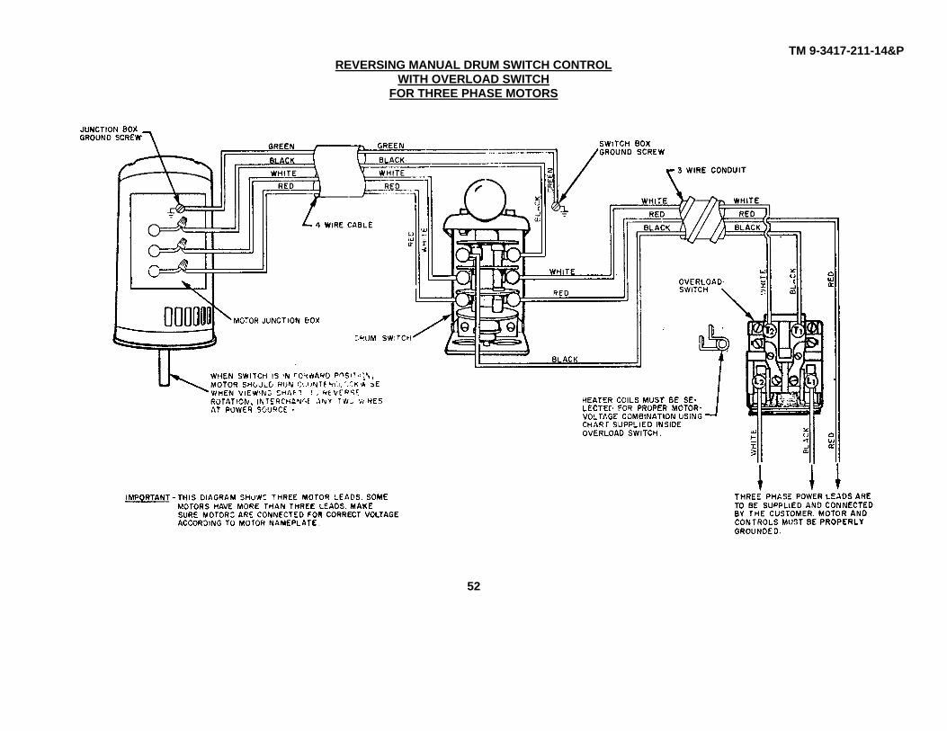
The wiring diagram shown on page 52 applies to all Vertical Mills wired for Cat. Nos. 49-479 and 49-482 Reversing Manual Drum Switch Control with Overload Switch for ThreePhase Motors.
The wiring diagram shown on page 53 applies to all Vertical Mills wired for Cat. Nos. 49-475 and 49-477 Reversing Drum Switch and Magnetic Starter with Full Voltage Controlfor 115 Volt Single Phase Motors.
The wiring diagram shown on page 54 applies to all Vertical Mills wired for Cat. Nos. 49-475 and 49-477 Reversing Drum Switch and Magnetic Starter with Full Voltage Controlfor 230 Volt Single Phase Motors.
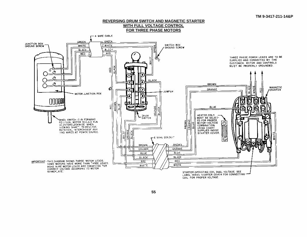
The wiring diagram shown on page 55 applies to all Vertical Mills wired for Cat. Nos. 49-481 and 49-483 Reversing Drum Switch and Magnetic Starter with Full Voltage Controlfor Three Phase Motors.
The wiring diagram shown on page 56 applies to all Vertical Mills wired for Cat. Nos. 49-679 and 49-680 Reversing Drum Switch and Magnetic Starter with Low Voltage Controlfor Three Phase Motors.
46

TM 9-3417-211-14&P
REVERSING MANUAL DRUM SWITCH CONTROLFOR 115 VOLT SINGLE PHASE MOTORS
47

TM 9-3417-211-14&PREVERSING MANUAL DRUM SWITCH CONTROL
FOR 230 VOLT SINGLE PHASE MOTORS
48

TM 9-3417-211-14&PREVERSING MANUAL DRUM SWITCH CONTROL
FOR THREE PHASE MOTORS
49

TM 9-3417-211-14&PREVERSING MANUAL DRUM SWITCH CONTROL
WITH OVERLOAD SWITCHFOR 115 VOLT SINGLE PHASE MOTORS
50

TM 9-3417-211-14&PREVERSING MANUAL DRUM SWITCH CONTROL
WITH OVERLOAD SWITCHFOR 230 VOLT SINGLE PHASE MOTORS
51
TM 9-3417-211-14&PREVERSING MANUAL DRUM SWITCH CONTROL
WITH OVERLOAD SWITCHFOR THREE PHASE MOTORS
52

TM 9-3417-211-14&PREVERSING DRUM SWITCH AND MAGNETIC STARTER
WITH FULL VOLTAGE CONTROLFOR 115 VOLT SINGLE PHASE MOTORS
53

TM 9-3417-211-14&PREVERSING DRUM SWITCH AND MAGNETIC STARTER
WITH FULL VOLTAGE CONTROLFOR 230 VOLT SINGLE PHASE MOTORS
54
TM 9-3417-211-14&PREVERSING DRUM SWITCH AND MAGNETIC STARTER
WITH FULL VOLTAGE CONTROLFOR THREE PHASE MOTORS
55

TM 9-3417-211-14&PREVERSING DRUM SWITCH AND MAGNETIC STARTER
WITH FULL VOLTAGE CONTROLFOR THREE PHASE MOTORS
56

TM 9-3417-211-14&P21-820 VARIABLE RATE POWER TABLE FEED
FORMILLING MACHINES
Fig. 1.
INTRODUCTION
The 21-820 Variable Rate Power Table Feed can be adapted to any Milling Machine. Ithas an extra wide feed range, from .5 to 22 inch/minute, which means that you canhandle an exceptionally wide range of materials. You can select a very slow feed forhardened alloy steels, or a very fast feed for soft non-ferrous metals.
The power feed fits in place of the right table handwheel. The left table handwheelremains on the mill and should be used to feed the table manually when the power’feedclutch lever is in the manual feed position.
The power table feed operates on regular 115V, 60 cycle, A.C., Single phase current only.
Cat. No. 21-838 Table Travel Limit Switch Kit is an excellent accessory to beused in conjunction with the Power Table Feed. It automatically shuts off the motor of theTable Feed if-the machine is left unattended.
57

TM 9-3417-211-14&P
INSTALLATION
1. Remove hex nut (A), right handwheel assembly(B), and woodruff key (C) Fig. 2.
2. Remove the two button head socket cap screws(D) Fig. 2. The end bracket (E), bearing holder withbearing (F), and spacer (G), may now be removed fromthe table.
Fig. 3.
5. Assemble the power feed unit to the adapter bracket(A) Fig. 4, using the two screws supplied. One of thescrews can be seen at (B) Fig. 4.
CAUTIONWhen assembling the power feed unit to the adapter,care should be taken so the key in the lead screwengages the keyway in the sleeve in the power feedunit.
Fig. 2.
3. Assemble the adapter bracket (A) Fig. 3, to thetable as shown using the two screws (B) which aresupplied with the power table feed.
4. Replace the key (C) Fig. 3, to the table lead screw.This key was removed in STEP 1.
Fig. 4.
58

TM 9-3417-211-14&P
OPERATION
The clutch lever (A) Fig. 5, is moved to the verticalposition for power feeding and to the horizontal positionfor manual operation. Select the desired table feed, byrotating the feed selector knob (D) Fig. 5. Place theclutch lever in the vertical position, and push the feedswitch (B) in the direction desired. At any time the rapidswitch (C) can override the selected feed in eitherdirection. To switch to manual feed, merely flip theclutch lever (A) to the horizontal position and feedmanually with the table handwheel.
ADJUSTING THE FEED SELECTOR KNOB
1. Operate the power feed.
2. Measure the distance the table travels in one minute.
3. Loosen set screw in the feed selector knob (D) Fig. 5,rotate the knob until it points to the corresponding feedon the chart, and tighten set screw.
Fig. 5.
OVERLOAD AND) SHIORT CIRCUIT PROTECTION
The motor used on your power table feed is equipped with an integral automatic reset thermaloverload protector. This device will cause the motor to shut off when overloaded. After the motor coolsthree to five minutes, it will automatically reset itself and the table will resume feeding.
The table feed is protected against short circuit by a Type 313-4 Amp. fuse. If short circuit occurs replacethe fuse ref. #63 on page 60.
CLUTCH ADJUSTMENTThe clutch used on the power table feed is adjustablefrom 0 to maximum feed pressure. It may be adjusted toslip under any predetermined load, e.g., to, slip at theend of the table travel to avoid damage to themechanism, to sense dull tools, and to protect motor andgears. If adjustment of the clutch is necessary, proceedas follows:
1. Remove the end cover plate from the power feed.2. Using the special wrench (A) Fig. 6, supplied with thepower feed, turn the clutch adjusting screw (B)counterclockwise to increase or clockwise to decreasethe clutch pressure. CA,UTION: Do not adjust the clutchtoo tight.
59

TM 9-3417-211-14&P
60
Replacement PartsRel.No.
Part. No. Description
60 SP-2480 Cable Clamp61 438-01-302-0168 Power Cord w/Terminals62 960-03-012-0410 Fuse Warning Decal63 438-01-027-0007 Fuse, Type 313-4 Amp - 1/4 x 1 1/264 438-01-007-0037 Fuse. Holder w/Lockwasher, Lock Nut,
and Knob65 438-01-011-0028 Insulator66 438-01-320-0065 12" Orange Wire Assembly, incl.:67 438-01-018-0032 Terminal68 SP-558 #8-32 x 1/4 Rd. Hd. Mach. Scr.69 438-01-307-0009 Circuit Board Assembly
* * 69 438-01-307-0010 Circuit Board Assembly w/Terminalsand Wire Nut
70 931-01-022-0476 Knob w/#8-32 x 1/4 Hex. Soc. Set Scr.
** Due to a recent improvement in the power feed circuit, the old circuit board andthe component parts are no longer available. The customer with the old stylepower feed circuit should order the 438-01-307-0010. Circuit Board Assembly,which includes all necessary parts for conversion to the new circuit See page67 for: information on installation of the new circuit.

TM 9-3417-211-14&P
Replacement PartsRef. Part No. Description Ref. Part No. DescriptionNo. No.
1 450-02-001-0006 Adapter 32 438-02-011-0007 Brush Holder (General Elec-2 SP-1615 13/32 x 13/16 x 1/16" Washer tric #625A679ABG1)3 SP-1704 3/8" Split Lockwasher 32 438-02-011-0014 Brush Holder Assembly (Rob-4 SP-775 3/8-16 x 1" Soc. Hd. Cap Scr. bins & Myers #7025285000)5 450-02-072-0003 Adapter Plate 33 438-02-011-0008 Brush Holder Cap (General Elec-6 SP-1604 5/16 x 3/4 x 1/16" Washer tric #8701254)7 SP-2086 5/16" Split Lockwasher 33 438-02-011-0015 Brush Holder Cap (Robbins &8 901-03-010-3315 5/16-18 x 1" Soc. Hd. Cap Scr. Myers #7025279001)9 450-02-013-0002 Gear Box 34 SP-S26 1/4-20 x 3/4" Hex. Hd. Scr.
10 SP-1604 5/16 x 3/4 x 1/16" Washer 35 SP-1702 1/4" Split Lockwasher11 SP-2086 5/16" Split Lockwasher 36 450-02-406-0001 Worm Shaft Assembly. incl:12 SP-757 5/16-18 x 3/4" Soc. Hd. Cap 37 901-04-150-9417 #10-32 x 3/16 Soc. Set Scr.
Screw 38 SP-6715 3/16 x 5/8" Roll Pin15 SP-286 #8-32 x 1/4" Soc Set Scr. 39 450-02-354-0002 Guard16 920-04-051-6667 Ball Bearing 40 SP-558 #8-32 x 1/4" Rd. Hd. Scr.17 450-02-105-0014 Sleeve 41 SP-2250 #4 - 3/16" Drive Screw18 SP-2605 #505 Hi-Pro Key 42 960-02-012-0032 Power Feed Plate19 450-02-028-0002 Clutch 43 450-02-406-0002 Clutch Shaft, including:20 920-45-001-6553 Needle Thrust Bearing 44 450-02-111-0001 Stud21 921-04-011-6556 Race 45 MK-5448 Knob22 928-01-041-5871 Spring 46 960-02-012-0033 Table Feed Dial Plate23 450-02-051-0007 Gear 47 920-23-012-0962 Needle Roller Bearing24 920-45-022-0961 Race 48 960-02-012-0034 Power Feed Switch Plate25 920-45-011-8061 Needle Thrust Bearing 49 450-02-331-0003 Gear Box Cover26 450-02-089-0003 Clutch Support Plate 50 SP-558 #8-32 x 1/4" Rd Hd Scr.27 901-04-021-6258 5/16-18 x 5/8" Adjustment Scr. 51 450-02-101-0001 Clutch Adjusting Wrench
with Nylok Insert * 450-02-061-0001 2 oz. Tube Grease (Esso30 438-02-314-0402 Motor Assembly, including: Nebula #2)31 438-02-007-0002 Brush Assembly (General Elec-
tric #625A619AHG5) Not shown31 438-02-007-0007 Brush Assembly (Robbins &
Myers #7025285000)
61

TM 9-3417-211-14&P
SCHEMATIC DIAGRAM
ASSEMBLING NEW CIRCUIT BOARD ASSEMBLYTO POWER FEEDS WITH THE OLD STYLE POWER FEED CIRCUIT
Remove old circuit board assembly, switches, relay and relay socket. Install the new terminals on the white power cordlead, the four motor leads and the red wire on the fuse holder. Use the wire nut to connect the black power cord lead tothe brown fuse lead. Plug in the terminals to the proper connections on the board1 (See printing on board and thediagram below.)The board is now ready for installation in the Gear Box. This is a simple matter of inserting the switches and potentiometerin the proper holes. The board is held in place by the nuts used on the three parts. Care must be taken to hold thepotentiometer by hand to keep it from turning as you tighten the nut to hold it in place.
62

TM 9-3417-211-14&P
NO. 2 24 VOLT SINGLE PHASE MAGNETIC STARTER MOTOR CONTROL SYSTEM
REPLACEMENT PARTS1 52-348 Control Station2 1225237 Contractor3 1086720 Transformer4 1225250 Overload Block5 Specify No. Heater
63

TM 9-3417-211-14&P
NO. 3 24 VOLT THREE PHASE MAGNETIC STARTER MOTOR CONTROL SYSTEM
REPLACEMENT PARTS1 52-348 Control Station2 1225237 Contractor3 1086753 Transformer4 1225235 Overload Block5 Specify No. Heater
64

TM 9-3417-211-14&P
NO. 4 24 VOLT SINGLE PHASE MAGNETIC STARTER MOTOR CONTROL SYSTEM
REPLACEMENT PARTS1 52-348 Control Station2 1225237 Contractor3 1086720 Transformer4 1225250 Overload Block5 Specify No. Heater
65

TM 9-3417-211-14&P
NO. 5 24 VOLT THREE PHASE MAGNETIC STARTER MOTOR CONTROL SYSTEM
REPLACEMENT PARTS1 52-348 Control Station2 1225237 Contractor3 1086720 Transformer4 1225235 Overload Block5 Specify No. Heater
66

TM 9-3417-211-14&P
NO. 6 24 VOLT SINGLE PHASE REVERSING MAGNETIC STARTER MOTOR CONTROL SYSTEM
REPLACEMENT PARTS1 49-420-for Lathes-49-673 for Mills2 1225278 Contractor3 1086720 Transformer4 1225250 Overload Block5 Specify No. Heater
67

TM 9-3417-211-14&PNO. 7 24 VOLT THREE PHASE REVERSING MAGNETIC STARTER MOTOR CONTROL SYSTEM
REPLACEMENT PARTS1 49-420-for Lathes-49-673 for Mills2 1225278 Contractor3 1086720 Transformer4 1225235 Overload Block5 Specify No. Heater
68

TM 9-3417-211-14&P
NO. 8 24 VOLT SINGLE PHASE MAGNETIC STARTER MOTOR CONTROL SYSTEM
REPLACEMENT PARTS1 52-348 Control Station2 1225237 Contractor3 1086720 Transformer4 1225250 Overload Block5 Specify No. Heater
69

TM 9-3417-211-14&P
NO. 9 24 VOLT SINGLE PHASE INTEGRAL MOTOR OVERLOAD PROTECTION MAGNETIC MOTOR CONTROLSYSTEM
REPLACEMENT PARTS1 52-348 Control Station2 1225237 Contractor3 1086720 Transformer4 1225234 Relay
70

TM 9-3417-211-14&P
NO. 10 24 VOLT THREE PHASE INTEGRAL MOTOR OVERLOAD PROTECTION MAGNETIC MOTOR CONTROLSYSTEM
71
REPLACEMENT PARTS1 52-348 Control Station2 1225237 Contractor3 1086720 Transformer4 1225234 Relay
71

TM 9-3417-211-14&P
NO. 11 24 VOLT SINGLE PHASE INTEGRAL MOTOR OVERLOAD PROTECTION MAGNETIC MOTOR CONTROLSYSTEM
REPLACEMENT PARTS1 438-01-017-0085 Control Station2 1225237 Contractor3 1086720 Transformer
72

TM 9-3417-211-14&P
NO. 12 24 VOLT THREE PHASE MAGNETIC STARTER MOTOR CONTROL SYSTEM
REPLACEMENT PARTS1 438-01-017-0085 Control Station2 1225237 Contractor3 1086753 Transformer4 1225235 Overload5 Specify No. Heater
73

TM 9-3417-211-14&P
NOTES ON TROUBLESHOOTING
Occasionally trouble may develop with your Power Tools. Usually, the trouble can be spotted immediately and corrected. Itis possible, however, a vibration, unusual noise, etc., may develop that would indicate a future malfunction of the machine.Naturally, immediate correction of this situation will, in most cases, prevent a costly breakdown. These trouble spots arenot always easy to find, but if the following steps are followed the trouble can usually be located and corrected.
1. Disconnect the motor from the belt, gearbox or cutter-head and turn it on. If the trouble is in the motor, it willbecome immediately evident (a bad bearing or line voltage loss).
2. Examine the condition of the belts and pulleys. If the pulley is cracked or broken, replace it. An out of balancepulley will soon create other problems. If the belt is frayed or excessively worn, replace it and find the cause.
3. Check the tightness of set screws. A loose set screw sounds like a bad bearing.
4. Check the alignment of the pulleys.
5. Check the arbor or the spindle. If the bearings are rough or the spindle is bent, replace same.
6. Examine the cutting tool or the blade. A dull blade will put undue strain on the machine.
If, after all these steps have been followed and the problem has not been corrected, contact your distributor for assistance.
74

TM 9-3417-211-14&P
HORIZONTAL/VERTICAL MILLING MACHINE
75

TM 9-3417-211-14&P
76

TM 9-3417-211-14&P
By Order of the Secretary of the Army:
E. C. MEYERGeneral, United States Army
Official: Chief of Staff
ROBERT M. JOYCEBrigadier General, United States Army
The Adjutant General
*U.S. GOVERNMENT PRINTING OFFICE: 1991-281-486-42115


PIN: 049923-000