tm 9-6920-461-35 department of the army technical …the clipper stage clips positive and negative...
TRANSCRIPT

TM 9-6920-461-35
DEPARTMENT OF THE ARMY TECHNICAL MANUAL
DIRECT AND GENERAL SUPPORT AND
DEPOT MAINTENANCE MANUAL:
GUIDED MISSILE FLIGHT CONTROL
TRAINING SETS DX-43 AND DX-44
(ENTAC ANTITANK GUIDED MISSILE
SYSTEM AND M22 GUIDED MISSILE
LAUNCHER HELICOPTER ARMAMENT
SUBSYSTEM)
This copy is a reprint which includes currentpages from Change 1.
HEADQUARTERS, DEPARTMENT OF THE ARMY
FEBRUARY 1965

TM 9-6920-461-35
TECHNICAL MANUAL HEADQUARTERS,DEPARTMENT OF THE ARMY
No. 9-6920-461-35 WASHINGTON, D.C., 3 February 1965
GUIDED MISSILE FLIGHT CONTROL TRAININGSETS DX-43 AND DX-4
-------------------
Paragraph Page
CHAPTER 1. INTRODUCTIONScope .................................................................................................... 1 3Errors, omissions, and corrections ......................................................... 2 3Maintenance responsibilities .................................................................. 3 3Forms, records, and reports ................................................................... 4 3Differences among models .................................................................... 5 3Nomenclature cross-reference ............................................................... 6 3
CHAPTER 2. THEORY OF OPERATION, DX-43 AND DX-44 SIMULATORSSection I. General Theory
Introduction............................................................................................ 7 5Method of simulation.............................................................................. 8 5Overall operation ................................................................................... 9 5
II. Detailed TheoryPower supplies....................................................................................... 10 6Input circuits .......................................................................................... 11 6Active P and Y channel circuits.............................................................. 12 20Dc amplifier ........................................................................................... 13 20Ac amplifier ........................................................................................... 14 22Gust generator....................................................................................... 15 22Time channel ......................................................................................... 16 22Regulated power supply......................................................................... 17 27DX-43 optical unit .................................................................................. 18 28DX-44 projector...................................................................................... 19 29
CHAPTER 3 MAINTENANCE INSTRUCTIONSSection I. General
Tools and equipment ............................................................................. 20 31Cleaning ................................................................................................ 21 31
II. TroubleshootingTesting AC amplifiers............................................................................. 22 31Testing DC amplifiers ............................................................................ 23 31Checking optical unit or projector potentiometer..................................... 24 31Computer checks ................................................................................... 25 32Troubleshooting tables........................................................................... 26 34
III. RepairGeneral.................................................................................................. 27 58Purging the DX-43 optical unit................................................................ 28 58
APPENDIX REFERENCES ...................................................................................... 61
1
}
TM 9-6920-461-35
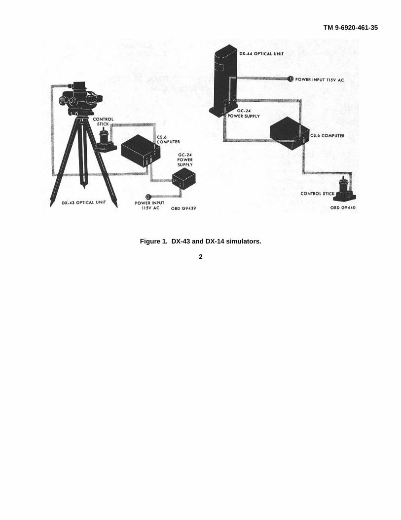
Figure 1. DX-43 and DX-14 simulators.
2

TM 9-6920-461-35
CHAPTER 1
INTRODUCTION
1. Scope
This manual contains instructions for maintainingDX-43 and DX-44 guided-missile flight-control trainers(fig. 1). These instructions are for direct support,general support, and depot maintenance technicians.For functional description, operating instructions, andbasic information on the trainers, see TM 9-6920-461-12.
2. Errors, Omissions, and Corrections
The direct reporting of errors, omissions, andrecommendations for improving this equipment manualis authorized and encouraged. DA Form 2028 will beused for reporting these improvements. This form maybe completed using pencil, pen, or typewriter. DA Form2028 will be completed in triplicate and forwarded directto: Commanding General, U. S. Army MissileCommand, ATTENTION: AMSMI-SMPT, RedstoneArsenal, Alabama 35809. One information copy will beprovided to the individual's immediate supervisor, (e. g.,officer, noncommissioned officer, superior, etc.).
3. Maintenance Responsibilities
Maintenance responsibilities are as indicated in themaintenance allocation chart in TM 9-6920-461-12, andreflected by the allocation of repair parts and tools listedin TM 9-6920-461-35P.
4. Forms, Records, and Reports
See TM 38-750 for instructions on the use andcompletion of all forms required for operating andmaintaining this equipment.
5. Differences Among Models
There is only one model of the DX43 simulator andone model of the DX-44 simulator in the field. Nomodification work orders have been incorporated.
6. Nomenclature Cross-Reference
Table 1 lists nomenclature used in this manualwhich differs from approved nomenclature.
Table 1. Nomenclature Cross-Reference
TM nomenclature Approved nomenclature Reference no.DX-43 simulator TRAINING SET, GUIDED MISSILE FLIGHT CONTROL (DX-43) 10173191
(ENTAC) (ground mounted)or
TRAINING SET, GUIDED MISSILE FLIGHT CONTROL (DX-43) 10173200(AGM-22)
DX44 simulator TRAINING SET, GUIDED MISSILE FLIGHT CONTROL (DX-44) 10173201(AGM-22)
Computer COMPUTER, CS6 10173161Regulated power POWER SUPPLY, REGULATED, GC24 10173181
supplyENTAC control stick ADAPTION KIT, GUIDED MISSILE FLIGHT CONTROL TRAIN- 10173190
adaption kit ING (DX-43) (ENTAC)AGM-22 control stick ADAPTION KIT, GUIDED MISSILE FLIGHT CONTROL TRAIN- 10173189adaption kit ING (AGM-22)DX-43 optical unit OPTICAL UNIT, DX-43 10173149DX-44 projector PROJECTOR UNIT, DX-44 10173193
3

TM 9-6920-461-35
Figure 2. Block diagram-DX-43 and DX-44.
4

TM 9-6920-461-35
CHAPTER 2
THEORY OF OPERATION, DX-43 AND DX-44 SIMULATORS
Section I. GENERAL THEORY7. Introduction
a. The DX43 simulator provides outdoor training infiring ENTAC or AGM-22 guided missiles. It consists ofan optical unit, a computer, and a regulated powersupply. Two control stick adaption kits are used with thesimulator, one for ENTAC training and another for AGM-22 training. These components, together withinterconnecting cables, make up the complete simulator.
b. The DX-44 simulator provides indoor training infiring the AGM-22 guided missile. It consists of aprojector set and a computer. The computer is identicalto the one used in the DX-43. A regulated power supply,identical with the one used with the DX-43 except forminor changes, is built into the projector set. Thecontrol stick adaption kit used with the DX-44 is thesame as the one used with the DX-43 for AGM-22training.
c. Operation of the DX-43 and DX-44 simulators issimilar. The difference between the two is that the DX-43 projects a light spot representing the missile directlyto the operator's eye, whereas the DX-44 projects thespot onto a screen. Since the two simulators havemuch in common, the following discussion of the DX-43theory of operation applies generally to the DX-44 also.The differences will be discussed later.
8. Method of Simulation
The adaption kit uses a modified control stick whichsimulates that used with the tactical missile system.Movements of the control stick control voltages in thecomputer which determine vertical and horizontalmovements of a light spot produced by the optical unit.The light spot, representing the flare of a missile inflight, is superimposed on the landscape that theoperator sees through the optical unit. The motions ofthe light spot, in response to movements of the controlstick, simulate motions of the actual missile.
9. Overall Operation (Fig. 2)a. The computer has three channels: yaw (Y), pitch
(P), and time (T). The control stick acts as a voltagedivider; some positive or negative voltage is picked offfor both Y and P control. In the computer and opticalunit, Y and P channels are similar in operation.
b. The signal from the control stick goes throughthe phase-lead network, which couples rapid changes involtage with less attenuation than slow changes. Thissimulates the quick react effect in the tactical system.The clipper stage clips positive and negative peaks ofthe signal, thus setting the voltage value for a 100%command. The missile-variables circuit, switched bythe front panel missile selection switch, simulatesnormal variations in missile performance.
c. The first control amplifier develops the signal forinitial Y and P velocity and, during missile time of flight,acts as the first integrator, computing drift velocity asaffected by the control signal. The second controlamplifier is the second integrator, computinginstantaneous elevation and azimuth positions. Theamplifier output is a varying ac voltage. This voltage isfed to the control winding of the servomoter, whichdrives the generator to produce an error signal. Themotor also controls, through a reduction gear, the angleof the mirror in elevation and azimuth and drives thepotentiometers which pick off the position voltage. Theposition voltage is fed back to the second controlamplifier while the computer is in the ready condition.These voltages, together with the voltages set on the Yand P initial position potentiometers, establish the angleof the mirror in elevation and azimuth at the beginningof a flight.
d. Missile velocity is assumed to be constant, sodistance traveled by the missile is directly proportionalto time. The time channel of the computer controlsmissile conditions that vary with distance. An acamplifier, supplied with a
5

TM 9-6920-461-35
constant voltage, drives a motor-generator. Thegenerator provides an error signal that is fed back to theamplifier input. The motor, through a reduction gear,drives three potentiometers and a commutator. Thecommutator controls the relay energizing sequence andthe potentiometers control a trigger for end-of-flightconditions, control the diminishing of light spot brilliancewith time, and supply to the timer amplifier an ac
voltage proportional to time. The timer amplifiersupplies the voltage for the reference windings of theoptical unit P and Y channel generators.
e. The gust generator, use of which is optional,supplies ac voltages varying at random in amplitude andphase to simulate the effect of atmospheric disturbanceson missile guidance.
Section II. DETAILED THEORY
10. Power Supplies
Note. Figure 3 is the computer main chassisschematic. Figures 4 through 7 are schematics of plug-in modules. Figure 8 is the M22 control stick schematic,and figure 9 is the ENTAC control stick schematic.
a. Power to operate the simulator is supplied eitherby a 24v battery or by the 24v regulated power supply(see paragraph 17 for detailed theory of the 24v supply).In the computer, the 24v is further regulated by atransistor regulator circuit which produces -22v and -16v. This circuit consists of Q-Y20, Q-Y21, and Q-Y22and associated parts. Two breakdown diodes connectedbetween ground and, through R80, the emitter of Q-Y20provide a 16v reference. Q-Y20 is controlled by Q-Y21and Q-Y22, so that Q-Y20 emitter is held at -22v. The -22v output, through the brilliance control and Q-Y15,supplies the spot light bulb in the optical unit.
b. The 400-cycle oscillator (400 cps pilot) (fig. 7)supplies 0-phase 400-cycle 48v for the time servomotorreference winding, 0-phase 400cycle 12v center tapped,and O0-degree-phase 400-cycle 3v center tapped tocontrol the power stage of the 400 cycle powergenerator. Q-Y4 is connected as a series Hartleyoscillator. Q-Y1 is a regulator. The Q-Y4 collector-to-base coupling coil is part of the transformer which drivesthe push-pull amplifier, Q-Y5 and Q-Y6. At the outputtransformer primary, a winding picks off part of thesignal, which is rectified by bridge CR-Y8. The rectifiedvoltage is applied to the voltage divider (R1, R2, R20)where part of it is picked off and applied to regulator Q-Y1 base. The difference between QY1 base voltageand the fixed emitter voltage determines the 6 collectorvoltage, which controls oscillator amplitude. An
increase in oscillation amplitude makes Q-Y1 base morenegative. Since the emitter voltage remains at a fixedvalue, collector voltage becomes more positive. As aresult, voltage supplying the oscillator becomes morepositive and oscillation amplitude decreases until itreaches the regulated amplitude.
c. Part of the 0 phase 400-cycle 12v signal isgiven a 90 degree phase rotation by R19-C11. This 90-degree-phase signal is amplified by Q-Y7. At the output3v center tapped is produced; this voltage controls the400-cycle power generator. Negative feedback from the83v output of the generator maintains a constant phasedifference between the 0-degree and the 90-degree-phase voltages.
d. The 400-cycle power generator (fig. 3) consistsof two transistors, Q-Y1 and Q-Y2, connected as a push-pull power amplifier, and an output transformer. Input is3v 400 cps from the oscillator. There are six outputvoltages: 68v 400 cps; and, after rectification andfiltering, +107.5v, -52.5v, 19 vdc, and 11 vdc. Theseare the voltage values during flight time.
11. Input Circuits (Fig. 3)
a. The control stick moves a potentiometer wiperarm in each axis, picking off a voltage between +107.5vand -52.5v. Since the stick may be moved slowly orquickly, the voltage picked off may change slowly orquickly. The waveform will vary, but for analysis oftheory can be treated as a square wave. We will followthe signal through the yaw channel; the operation in thepitch channel is identical. This voltage from the control-stick potentiometer is
6

TM 9-6920-461-35
Apparatus List for the Computer Chassis, Figure 3
Referencedesignator Description Reference no.
C1 CAPACITOR: electrolytic, 1500 uf 6920-960-8473C7 CAPACITOR: fixed, electrolytic, 40v, 64 uf 10022528.C8 CAPACITOR: fixed, electrolytic, 40v, 32 uf 10022523C9, C10 CAPACITOR: paper, 0.16 uf 10173167C10.1 Selected at testC11, C12 CAPACITOR: paper, 0.1 uf 10173168C11.1 Selected at testC13, C14 CAPACITOR: fixed, 0.47 ufC15, C16 CAPACITOR: fixed, metalized paper, 200v, 1 uf ± 56% 5910-833-5785C17, C18 CAPACITOR: fixed, metalized paper, 160v, 0.1 uf ± 6% 10022510C19 CAPACITOR: fixed, metalized paper, 200v, 0.47 uf ± 20% 5910-519-9738CR-Y12 DIODE: 10J2 10022270CR-Y16-CR-Y18 DIODE: 108Z4 (special) 10022277CR-Y19 DIODE: 108Z4 (special) 10022278DS1, DS2 LAMP: midget base, 28v, 0.04 amp 10173174DS3 COUNTER: 6 digits 10173245F1 FUZE 10134548L1, L2 COIL 10022509Q-Y1, Q-Y2 TRANSISTOR: ASZ18 (special) 10022261Q-Y1S TRANSISTOR: ASZ18 (special) 10173274Q-Y20 TRANSISTOR: ASZ18 (special) 10173273Q-Y21 TRANSISTOR: 2N527 10173175R1 RESISTOR: fixed, composition, 1/2 w, 820 ohms ± 5% 5905-171-1999R2, RS RESISTOR: fixed, 1 ohm 10022550RP5 RESISTOR: variable, lw, 1K ohms ± 10% 10173170RP6 RESISTOR: variable, lw, 5K ohms ± 10% 10173171RP7, RP8 RESISTOR: variable, lw, 5K ohms ± 10% 10173172R8 RESISTOR: fixed, composition, %w, 10K ohms ± 65% 5906-185-8610R9 RESISTOR: fixed, composition, %w, 1K ohms ± 65% 5905-195-6806RP9, RP10 Same as RP7R10 RESISTOR: fixed, composition, %w, 1OOK ohms ± 5% 5905-195-6761R11 RESISTOR: fixed, composition, %w, 5.6K ohms ± 5% 5905-195-6453R12 RESISTOR: fixed, composition, %w, 6.8K ohms ± 5% 5905-279-3503R13 RESISTOR: fixed, composition, %w, 2.2K ohms ± 5% 5905-279-1876R14 Selected at testR15 RESISTOR: fixed, composition, %w, 180 ohms ± 5% 5905-279-8514R16 RESISTOR: fixed, composition, %w, 150 ohms ± 5% 5905-299-1541R17 RESISTOR: fixed, composition, %w, 330 ohms ± 5% 5905-192-3971R18 Same as R10R19 Selected at testR20 RESISTOR: fixed, 68K ohms ± 1% 10022588R21 Selected at testR22 RESISTOR: fixed, 18K ohms ± 1% 10022585R23 RESISTOR: 47K ohms 10173272R24 Selected at testR25 RESISTOR: fixed, composition, %w, 270 ohms ± 5% 5905-171-2006R26 RESISTOR: fixed, composition, %w, 470 ohms ± 65% 5905-192-3973R27 RESISTOR: fixed, 82K ohms ± 10% 10022589R28 RESISTOR: fixed, 865K ohms ± 1% 10022603R29 RESISTOR: fixed, composition, %w, 470 ohms ± 5% 5905-192-8973R30 RESISTOR: fixed, 590K ohms ± 1% 10022601R31 RESISTOR: fixed, 330K ohms, ± 1% 10022593R32 RESISTOR: fixed, 1M ohmsR33 RESISTOR: fixed, film, 1.2M ohms :± 2% 10022570R34 RESISTOR: fixed, 390K ohmsR35 RESISTOR: fixed, 330K ohmsR36 RESISTOR: fixed, 470K ohms
9

TM 9-6920-461-35
Apparatus List for the Computer Chassis, Figure 3Referencedesignator Description Reference no.
R87 RESISTOR: fixed, 150K ohmsR38 RESISTOR: fixed, 270K ohmsR39 RESISTOR: fixed, 68K ohmsR40 Selected at testR41 Same as R29R42 RESISTOR: fixed, 590K ohms ± 1% 10022601R48 Same as R31R44 RESISTOR: fixed, 560K ohmsR45 RESISTOR: fixed, 120K ohmsR46 Same as R82R47 Same as R33R48 RESISTOR: fixed, 270K ohmsR49 RESISTOR: fixed, 220K ohmsR60 RESISTOR: fixed, 330K ohmsR61 RESISTOR: fixed, 130K ohmsR52 RESISTOR: fixed, 220K ohmsR53 RESISTOR: fixed, 56K ohmsR54 Selected at testR55 RESISTOR: fixed, composition, ½ w, 16K ohms ± 5% 5906-279-2616R56 RESISTOR: fixed, composition, ½ w, 47K ohms ± 5% 5906-254-9201R57 Same as R55R58 Same as R56R59 Same as R29R60 RESISTOR: fixed, 430K ohms ± 1% 10022594R61 RESISTOR: fixed, 535K ohms ± 5% 10022699R62 RESISTOR: fixed, 270 ohms ± 1% 10022592R68 RESISTOR: fixed, 255 ohms ± 1% 10022591R64 RESISTOR: fixed, 89K ohms ± 1% 10022587R65 Same as R29R66 Same as R60R67 RESISTOR: fixed, 535K ohms ± 1% 10022599R68 Same as R62R69 Same as R63R70 Same as R64R71 Selected at testR72 Selected at testR73 RESISTOR: fixed, 270 ohmsR74 RESISTOR: fixed, 10 ohmsR75 RESISTOR: fixed, 3w, 1.8 ohms 10022551R76, R77 RESISTOR: fixed, composition, ½ w, 1K ohms ± 5% 5905-19-6806R81 Selected at testR82 RESISTOR: fixed, 22K ohms ± 1% 10022586R88, R84 RESISTOR: fixed, composition, %w, 56 ohms ± 5% 5905-279-1897S1 SWITCH: toggle, double pole, waterproof 10022488S2 SWITCH: pushbutton 10022487S8 SWITCH: rotary 10022489S-P4 Part of RESISTOR ASSEMBLY 10178173S65 SWITCH: rotary 10022490TBJ1 TERMINAL STRIP 10173268TBJ2 TERMINAL STRIP 10173267TB-J TERMINAL STRIP 10178269TB-J4 TERMINAL STRIP 10173270TB-J6 TERMINAL STRIP 10173265TB-J7 TERMINAL STRIP 10173271TBJ8 TERMINAL STRIP 10173266TB-J9 TERMINAL STRIPTB-W TERMINAL STRIPK-A to K-E RELAY: 24V, 6K ohms coil resistance, 100mw 10173165
10

TM 9-6920-461-35
Figure 3. Computer chassis schematic.
7

Figure 4. A7-2 amplifier schematic.
TM 9-6920-461-35
Figure 5. A4-5 amplifier schematic.
11

TM 9-6920-461-35
Apparatus List for the Power, Supply 31.200, Figure 3
Referencedesignator Description Reference no.
C2 CAPACITOR: fixed, cartridge, 25v, 3000 uf 10022533C3 CAPACITOR: fixed, electrolytic, 250v, 32 uf 10022522C4 CAPACITOR: fixed, electrolytic, 64v, 32 uf 10022524C5, C6 CAPACITOR: fixed, electrolytic, 25v, 64 uf 10022527C20 CAPACITOR: paper, 0.1 uf 10173168CR-Y3, CR-Y23 DIODE GROUP: special, 108Z4 (special), 1075Z4 (special) 0022553CR-Y4, CR-Y5 DIODE: 1N647 5960-682-2699CR-Y6-CR-Y11 DIODE: 62J2 10022273Q-Y22 TRANSISTOR: 2N527 10173175R4, R5 RESISTOR: fixed, composition, ½ w, 1.5K ohms ± 5% 5905-279-1757R6 RESISTOR: fixed, composition, ½ w, 1K ohms ± 5% 5905-195-6806R7 RESISTOR: fixed, composition, ½ w, 470 ohms ± 5% 5906-192-3978R78 Same as R4R79 RESISTOR: fixed, composition, ½ w, 560 ohms ± 5% 5905-195-6800R80 RESISTOR: fixed, composition, ½ w, 120 ohms ± 5% 5905-252-5484T1 TRANSFORMER 10022501
Apparatus List for the Amplifier A1.2, Figure 4
Referencedesignator Description Reference no.
C1 CAPACITOR: fixed, metalized mylar, 200v,- 1 uf 10022514C2, C3 CAPACITOR: fixed, electrolytic, 10v, 64 uf 10172526C4 CAPACITOR: fixed, metalized paper, 200v, 5000 uuf 0172585C6 CAPACITOR: fixed, 40v, 3.2 uf 10172516C6, C7 CAPACITOR: fixed, electrolytic, 26v, 26 uf 10022520CR-Y10-CR-Y13 DIODE: 14P1 10022271MR1 MODULATOR: ring 10022497Q-Y6-Q-Y7 TRANSISTOR: 2N527 10173175Q-Y8, Q-Y9 TRANSISTOR: 2N1056 5960-806-8312Q-Y14-Q-Y17 TRANSISTOR: 2N527 10178175R5 RESISTOR: fixed, composition, ½ w, 2.7K ohms ± 5% 5905-279-1880R6 RESISTOR: fixed, composition, ½ w; 16K ohms ± 5% 5905-279-2616R7 RESISTOR: fixed, composition, ½ w, 1.6K ohms ± 5% 5905-279-1757R8 RESISTOR: fixed, composition, ½ w, 27K ohms ± 5% 5905-279-8499R9 RESISTOR: fixed, composition, ½ w, 4.7K ohms ± 5% 5905-279-3504R10 RESISTOR: fixed, composition, ½ w, 10K ohms ± 5% 5906-185-8510R11 RESISTOR: fixed, composition, ½ w, 1K ohms ± 5% 5905-195-6806R12 RESISTOR: fixed, composition, ½ w, 4.7K ohms ± 5% 5905-279-8504R13 RESISTOR: fixed, composition, ½ w, 10K ohms ± 5% 5905-185-8510R14 RESISTOR: fixed, composition, ½ w, 2.2K ohms ± 5% 5906-279-1876R15 RESISTOR: fixed, composition, ½ w, 3.9K ohms ± 5% 5905-279-8505R16 RESISTOR: fixed, composition, ½ w, 12K ohms ± 5% 5905-279-8502R17 RESISTOR: fixed, composition, ½ w, 27K ohms ± 5% 5906-279-8499R18 RESISTOR: fixed, composition, ½ w, 100K ohms ± 5% 5905-195-6761R19, R20 RESISTOR: fixed, composition, ½ w, 1K ohms ± 5% 5905-195-6806R21, R22 RESISTOR: fixed, composition, ½ w, 220 ohms ± 5% 5905-279-3513R23 RESISTOR: fixed, composition, ½ w, 27K ohms ± 5% 5905-279-3499R24, R25 RESISTOR: fixed, composition, ½ w, 220 ohms ± 5% 5906-279-3513R26 RESISTOR: fixed, composition, ½ w, 27K ohms ± 5% 5905-279-3499R27, R28 RESISTOR: fixed, composition, ½ w, 47 ohms ± 5% 5905-262-4018R29 RESISTOR: fixed, composition, ½ w, 10K ohms ± 5% 5906-185-8610R30 RESISTOR: fixed, composition, ½ w, 470 ohms ± 5% 5905-192-3973R31 RESISTOR: fixed, composition, ½ w, 15K ohms ± 5% 5905-279-2616R32 RESISTOR: fixed, composition, ½ w, 470 ohms ± 5% 5905-192-3973T1 TRANSFORMER 10022504T2 TRANSFORMER 10022505T3 TRANSFORMER 10022506
13
TM 9-6920-461-35
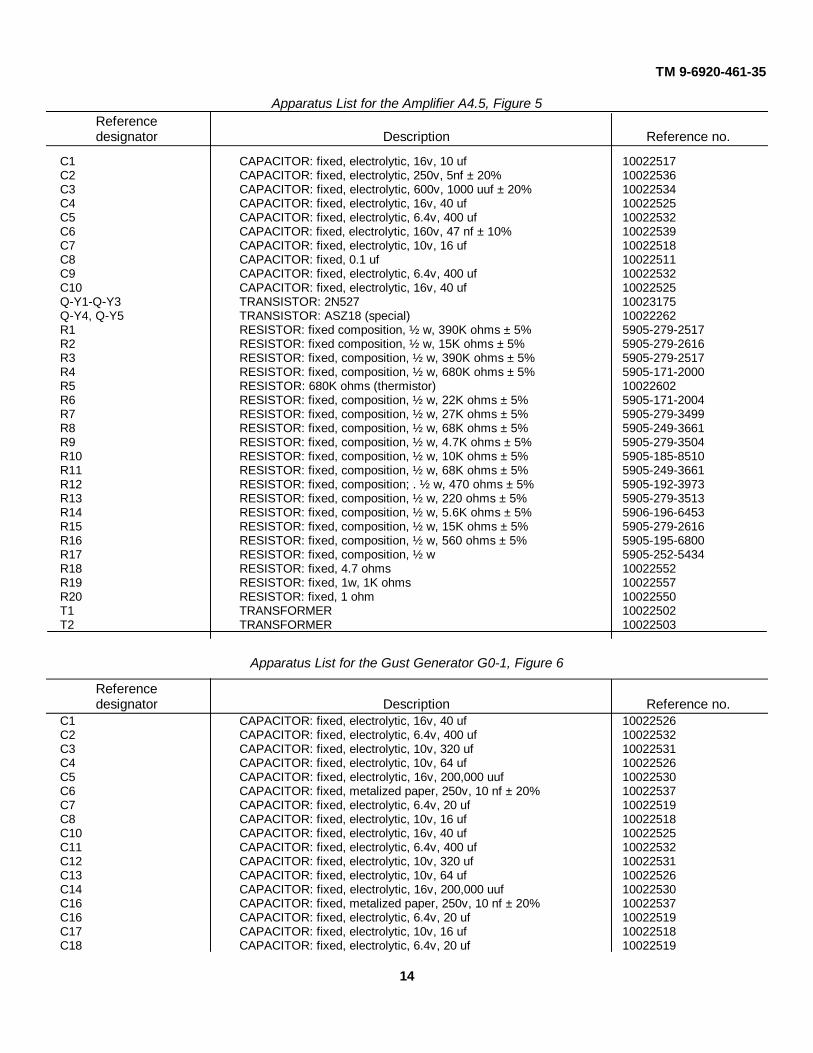
Apparatus List for the Amplifier A4.5, Figure 5Referencedesignator Description Reference no.
C1 CAPACITOR: fixed, electrolytic, 16v, 10 uf 10022517C2 CAPACITOR: fixed, electrolytic, 250v, 5nf ± 20% 10022536C3 CAPACITOR: fixed, electrolytic, 600v, 1000 uuf ± 20% 10022534C4 CAPACITOR: fixed, electrolytic, 16v, 40 uf 10022525C5 CAPACITOR: fixed, electrolytic, 6.4v, 400 uf 10022532C6 CAPACITOR: fixed, electrolytic, 160v, 47 nf ± 10% 10022539C7 CAPACITOR: fixed, electrolytic, 10v, 16 uf 10022518C8 CAPACITOR: fixed, 0.1 uf 10022511C9 CAPACITOR: fixed, electrolytic, 6.4v, 400 uf 10022532C10 CAPACITOR: fixed, electrolytic, 16v, 40 uf 10022525Q-Y1-Q-Y3 TRANSISTOR: 2N527 10023175Q-Y4, Q-Y5 TRANSISTOR: ASZ18 (special) 10022262R1 RESISTOR: fixed composition, ½ w, 390K ohms ± 5% 5905-279-2517R2 RESISTOR: fixed composition, ½ w, 15K ohms ± 5% 5905-279-2616R3 RESISTOR: fixed, composition, ½ w, 390K ohms ± 5% 5905-279-2517R4 RESISTOR: fixed, composition, ½ w, 680K ohms ± 5% 5905-171-2000R5 RESISTOR: 680K ohms (thermistor) 10022602R6 RESISTOR: fixed, composition, ½ w, 22K ohms ± 5% 5905-171-2004R7 RESISTOR: fixed, composition, ½ w, 27K ohms ± 5% 5905-279-3499R8 RESISTOR: fixed, composition, ½ w, 68K ohms ± 5% 5905-249-3661R9 RESISTOR: fixed, composition, ½ w, 4.7K ohms ± 5% 5905-279-3504R10 RESISTOR: fixed, composition, ½ w, 10K ohms ± 5% 5905-185-8510R11 RESISTOR: fixed, composition, ½ w, 68K ohms ± 5% 5905-249-3661R12 RESISTOR: fixed, composition; . ½ w, 470 ohms ± 5% 5905-192-3973R13 RESISTOR: fixed, composition, ½ w, 220 ohms ± 5% 5905-279-3513R14 RESISTOR: fixed, composition, ½ w, 5.6K ohms ± 5% 5906-196-6453R15 RESISTOR: fixed, composition, ½ w, 15K ohms ± 5% 5905-279-2616R16 RESISTOR: fixed, composition, ½ w, 560 ohms ± 5% 5905-195-6800R17 RESISTOR: fixed, composition, ½ w 5905-252-5434R18 RESISTOR: fixed, 4.7 ohms 10022552R19 RESISTOR: fixed, 1w, 1K ohms 10022557R20 RESISTOR: fixed, 1 ohm 10022550T1 TRANSFORMER 10022502T2 TRANSFORMER 10022503
Apparatus List for the Gust Generator G0-1, Figure 6
Referencedesignator Description Reference no.
C1 CAPACITOR: fixed, electrolytic, 16v, 40 uf 10022526C2 CAPACITOR: fixed, electrolytic, 6.4v, 400 uf 10022532C3 CAPACITOR: fixed, electrolytic, 10v, 320 uf 10022531C4 CAPACITOR: fixed, electrolytic, 10v, 64 uf 10022526C5 CAPACITOR: fixed, electrolytic, 16v, 200,000 uuf 10022530C6 CAPACITOR: fixed, metalized paper, 250v, 10 nf ± 20% 10022537C7 CAPACITOR: fixed, electrolytic, 6.4v, 20 uf 10022519C8 CAPACITOR: fixed, electrolytic, 10v, 16 uf 10022518C10 CAPACITOR: fixed, electrolytic, 16v, 40 uf 10022525C11 CAPACITOR: fixed, electrolytic, 6.4v, 400 uf 10022532C12 CAPACITOR: fixed, electrolytic, 10v, 320 uf 10022531C13 CAPACITOR: fixed, electrolytic, 10v, 64 uf 10022526C14 CAPACITOR: fixed, electrolytic, 16v, 200,000 uuf 10022530C16 CAPACITOR: fixed, metalized paper, 250v, 10 nf ± 20% 10022537C16 CAPACITOR: fixed, electrolytic, 6.4v, 20 uf 10022519C17 CAPACITOR: fixed, electrolytic, 10v, 16 uf 10022518C18 CAPACITOR: fixed, electrolytic, 6.4v, 20 uf 10022519
14

Figure 6. G0-1 generator schematic.
TM 9-6920-461-35
Figure 7. G4-2 oscillator schematic
15
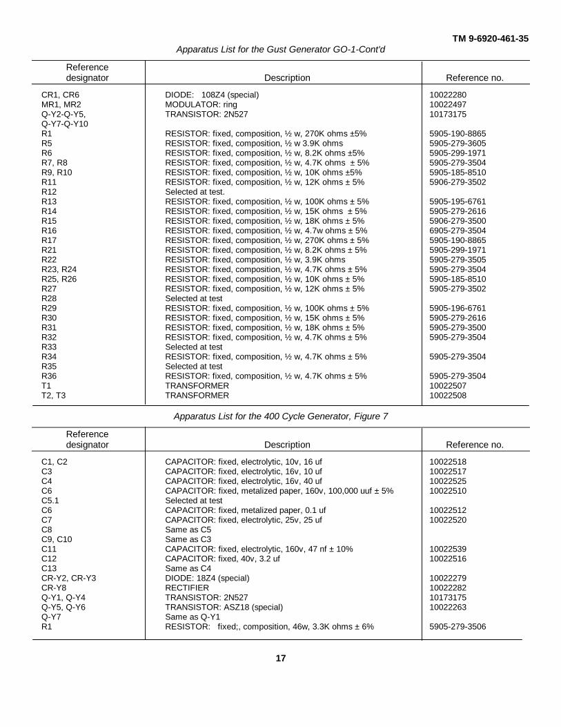
TM 9-6920-461-35Apparatus List for the Gust Generator GO-1-Cont'd
Referencedesignator Description Reference no.
CR1, CR6 DIODE: 108Z4 (special) 10022280MR1, MR2 MODULATOR: ring 10022497Q-Y2-Q-Y5, TRANSISTOR: 2N527 10173175Q-Y7-Q-Y10R1 RESISTOR: fixed, composition, ½ w, 270K ohms ±5% 5905-190-8865R5 RESISTOR: fixed, composition, ½ w 3.9K ohms 5905-279-3605R6 RESISTOR: fixed, composition, ½ w, 8.2K ohms ±5% 5905-299-1971R7, R8 RESISTOR: fixed, composition, ½ w, 4.7K ohms ± 5% 5905-279-3504R9, R10 RESISTOR: fixed, composition, ½ w, 10K ohms ±5% 5905-185-8510R11 RESISTOR: fixed, composition, ½ w, 12K ohms ± 5% 5906-279-3502R12 Selected at test.R13 RESISTOR: fixed, composition, ½ w, 100K ohms ± 5% 5905-195-6761R14 RESISTOR: fixed, composition, ½ w, 15K ohms ± 5% 5905-279-2616R15 RESISTOR: fixed, composition, ½ w, 18K ohms ± 5% 5906-279-3500R16 RESISTOR: fixed, composition, ½ w, 4.7w ohms ± 5% 6905-279-3504R17 RESISTOR: fixed, composition, ½ w, 270K ohms ± 5% 5905-190-8865R21 RESISTOR: fixed, composition, ½ w, 8.2K ohms ± 5% 5905-299-1971R22 RESISTOR: fixed, composition, ½ w, 3.9K ohms 5905-279-3505R23, R24 RESISTOR: fixed, composition, ½ w, 4.7K ohms ± 5% 5905-279-3504R25, R26 RESISTOR: fixed, composition, ½ w, 10K ohms ± 5% 5905-185-8510R27 RESISTOR: fixed, composition, ½ w, 12K ohms ± 5% 5905-279-3502R28 Selected at testR29 RESISTOR: fixed, composition, ½ w, 100K ohms ± 5% 5905-196-6761R30 RESISTOR: fixed, composition, ½ w, 15K ohms ± 5% 5905-279-2616R31 RESISTOR: fixed, composition, ½ w, 18K ohms ± 5% 5905-279-3500R32 RESISTOR: fixed, composition, ½ w, 4.7K ohms ± 5% 5905-279-3504R33 Selected at testR34 RESISTOR: fixed, composition, ½ w, 4.7K ohms ± 5% 5905-279-3504R35 Selected at testR36 RESISTOR: fixed, composition, ½ w, 4.7K ohms ± 5% 5905-279-3504T1 TRANSFORMER 10022507T2, T3 TRANSFORMER 10022508
Apparatus List for the 400 Cycle Generator, Figure 7
Referencedesignator Description Reference no.
C1, C2 CAPACITOR: fixed, electrolytic, 10v, 16 uf 10022518C3 CAPACITOR: fixed, electrolytic, 16v, 10 uf 10022517C4 CAPACITOR: fixed, electrolytic, 16v, 40 uf 10022525C6 CAPACITOR: fixed, metalized paper, 160v, 100,000 uuf ± 5% 10022510C5.1 Selected at testC6 CAPACITOR: fixed, metalized paper, 0.1 uf 10022512C7 CAPACITOR: fixed, electrolytic, 25v, 25 uf 10022520C8 Same as C5C9, C10 Same as C3C11 CAPACITOR: fixed, electrolytic, 160v, 47 nf ± 10% 10022539C12 CAPACITOR: fixed, 40v, 3.2 uf 10022516C13 Same as C4CR-Y2, CR-Y3 DIODE: 18Z4 (special) 10022279CR-Y8 RECTIFIER 10022282Q-Y1, Q-Y4 TRANSISTOR: 2N527 10173175Q-Y5, Q-Y6 TRANSISTOR: ASZ18 (special) 10022263Q-Y7 Same as Q-Y1R1 RESISTOR: fixed;, composition, 46w, 3.3K ohms ± 6% 5905-279-3506
17

TM 9-6920-461-35
Apparatus List for the 400 Cycle Generator— Cont'd
Referencedesignator Description Reference no.
R2 RESISTOR: fixed, composition, ½ w, 1.5K ohms ± 5% 5905-279-1757R3 RESISTOR: fixed, composition, ½ w, 4.7K ohms ± 5% 5906-279-3504R4 Same as R2R5 RESISTOR: fixed, composition, ½ w, 330 ohms ± 5% 6906-192-3971R6 Same as R1R7 RESISTOR: fixed, composition, ½ w, 1K ohms ± 5% 5906-195-6806R8 RESISTOR: fixed, composition, ½ w, 10K ohms ± 5% 5905-186-8510R9 RESISTOR: fixed, composition, ½ w, 15 ohms ± 5% 5905-279-3521R10 Same as R1R11 RESISTOR: fixed, composition, ½ w, 10 ohms ± 5% 5905-190-8888R12 Selected at testR13 RESISTOR: fixed, composition, ½ w, 470 ohms ± 5% 5905-192-3973R14 RESISTOR: fixed, composition, ½ w, 1.5K ohms ± 5% 5906-279-1767R15, R16 RESISTOR: fixed, composition, ½ w, 10K ohms ± 5% 5905-185-8510R17 Selected at testR18 RESISTOR: fixed, composition, ½ w, 22K ohms ± 5% 5905-171-2004R19 RESISTOR: fixed, composition, ½ w, 12K ohms ± 5% 5905-279-3502R20 RESISTOR: adjustable, 1K ohms 10022556R21 Same as R14T1 TRANSFORMER 1002250T2 TRANSFORMER 10022499T3 TRANSFORMER 10022498
Figure 8. M22 control stick schematic.
18

TM 9-6920-461-35
Figure 9. Modified ENTAC GCU schematic.
19

TM 9-6920-461-35
applied to the computer phase-lead circuit, C13, R32,and R33. Rapid voltage changes caused by rapidmovements of the control stick are coupled around R32-R33 and through C13. Thus a rapid change of stickposition will produce a quick reaction of the simulatedmissile. The phase-lead circuit is switched by the missilevariables control (par. 12c).
b. The clipper, consisting of breakdown diodesCR-Y16 and CR-Y17, establishes at +8v the maximumvoltage which can be applied in the Y channel. Thismaximum command in the simulator corresponds to themaximum command in the tactical control system.
12. Active P and Y Channel Circuits (Fig. 3)
a. The first control amplifier is a dc amplifier,the output of which is modulated 400cps signal, 0- or180-degree phase. Together with an RC circuit, R30-C15, it determines drift velocity of the light spot. Wheninitial velocity is applied, C15 is shunted by R31, and theamplifier acts as
Figure 10. Integrator waveforms.
a summing amplifier, charging C15 to a potentialdetermined by voltage applied by the initial velocitypotentiometer. Upon firing, R31 and the initial velocityvoltage are switched out of the circuit, and the amplifierthen acts as an integrator (fig. 10), computing driftvelocity as affected by the signals from the control stick.The output of the dc amplifier which goes, to the secondcontrol amplifier is modulated 400 cps act (See par. 13for theory of operation of the dc amplifier.)
b. The second control amplifier is an acamplifier which delivers a variable voltage to the controlwinding of the servo motor. The value of the voltagedepends on control signals from the stick and initialvelocity circuit. The motor drives a generator producinga voltage proportional to its speed. This voltage is fedback to the amplifier input. The motor also, through areduction gear, moves the mirror in yaw. Apotentiometer driven by the same shaft picks off avoltage indicating the mirror position. This voltage isapplied to the input of the second control amplifier untilfiring. (See par. 14 for theory of operation of the acamplifier.)
c. The missile-variables circuit is a front-panel-switched voltage divider which, together with theswitched phase-lead network, allows the simulation offour typical kinds of missile guidance characteristics:normal missile, sensitive missile, sluggish missile, andsensitive missile with poor phase lead.
13. DC Amplifier A1-2
The dc amplifier receives the control signal, whichis varying dc, modulates with it a 400cycle carrier, andamplifies the resulting 0-degree or 180-degree phasesignal. Both the signal from the control stick and theinitial velocity signal are fed into the dc amplifier. Themodulated ac output of the dc amplifier is fed to the acamplifier.
a. The dc amplifier (fig. 4) is a plug-in module,completely transistorized. It is composed of a modulator,an ac amplifier, and a demodulator.
b. The modulator circuit consists of T1, part ofT3, and a silicon diode ring. A reference 0-degree phase400cps ac voltage is supplied to the ring through T3.The modulator output at T1 secondary is ac, with thephase ((0-degree or 180-degree) determined by thepolarity of the dc
20

TM 9-6920-461-35
input signal and the amplitude determined by theamplitude of the dc input. (The output signal eventuallyarrives at the control winding of the optical unit motor,where phase determines direction, and amplitude speed,of rotation.) To understand how the modulator works,let's analyze current flow for two different polarity dcinputs during a positive alternation of the ac reference.
c. With the ac reference positive and apositive de input, current flow in the modulator circuit isas follows. (See figure 11, where diodes are numberedfor convenience in explaining operation.) Note that theratio between dc input and ac reference amplitudes atthe diode ring is at least 1: 40. Starting from the centertap of T3 secondary winding, current flows through thewinding, out T3 terminal 5, and through CR4. At thejunction of CR4 and CR3, current divides. Because thepositive potential at this point resulting from the dc inputsignal is low compared to the positive potential on theother side of CR3, CR3 is forward biased and a largepart of the current flows through CR3 and back throughT3 secondary. A second part of the current flowsthrough T1 primary, out the centertap, to ground throughthe power supply, and back into T3 secondary throughthe grounded centertap. This causes current flow in T1secondary in a direction so that the output at terminal 5is negative.
d. With the ac reference positive and anegative dc input, current flow is through the same twodiodes, but in the opposite direction in the same half ofT1 primary. Starting again at the center tap of T3secondary, current flows through the winding, out T3terminal 5, and through CR4. At the junction of CR4and CR3, this current is joined by one coming from thedc input through T1 center tap and T1 winding.The combined current flows through CR3 into T3secondary. Part of the current flows to ground at T3centertap, through the power supply, and back to the dcinput. The rest of the current flows on through T3secondary and out terminal 5. Current flow in half of T1primary is opposite in direction to that in c above, andthe output at terminal 5 is positive. Thus the change inpolarity of the input has reversed the phase of theoutput, which is ac because the input is in series with theac reference. And
Figure 11. Modulator current flow.
since T1 primary is in series with the input, outputamplitude depends on the dc input amplitude, with theac reference voltage remaining constant in amplitude,peak-to-peak.
e. When the ac reference becomes negative,current flow is similar except that it is through CR1 andCR2 and the other half of T1 primary.
The output phase relative to the ac reference stillis determined by dc input polarity, and the outputamplitude by dc input amplitude.
f. In T1 secondary circuit, current flowsthrough a voltage divider, R7, R8, R10, R6.
21
TM 9-6920 461-35
Voltage dropped across R7 is applied to Q-Y5 base.g. Q-Y5 and Q-Y6 are voltage amplifiers. Q-
Y7 is a phase splitter for the push-pull power amplifierstage, Q-Y8 and Q-Y9. From transformer T2, themodulated signal is fed to the demodulator, Q-Y14 - Q-Y17. The demodulator output, at connection 8, is dcvarying from— 15v to +15v, 180 degrees out of phasewith the input. This output is coupled to the inputthrough feedback capacitor C15 so that the amplifieracts as an integrator. The signal output, at connection 6or 7, is 0-degree or 180-degree ac, 400 cps, 0-15v. It iscoupled to the ac amplifier.
14. AC Amplifier A 4-5 (Fig. 5)
The ac power amplifier has five inputs, two orthree of which are combined to produce an outputcontrolling the instantaneous angle of the light spot inazimuth (or, in the P channel, elevation ). It consists ofan emitter-follower impedance-matching stage and threestages of amplification. Its output goes to theservomotor control winding.
a. Q-Y1 is an emitter follower used to matchinput impedance of Q-Y2 to output impedance of theprevious stage. Q-Y2 and Q-Y3 are power amplifierstages. Q-Y4 and Q-Y5 make up a push-pull poweramplifier.
b. C2 and R1, at the input, provide highfrequency compensation, as do C6 and R11 in thecoupling circuit between Q-Y2 and Q-Y3. These twonetworks compensate the amplifier for phase-advancesignals, which would otherwise be attenuated becauseof the amplifier's poor high frequency response.
c. Five signals feed into the ac amplifier. Twosignals are used only before firing time, and three (oneof which is optional) are used only during flight time (fig.3).
(1) The initial position signal is 400 cps,0-6v. The voltage level is adjustedby R9. This signal, used only beforefiring, establishes the startingposition of the mirror and, therefore,the light spot representing themissile.
(2) The initial-position feedback voltageindicates the position of the mirror.It is also 400 cps, 0-6v. The exactvoltage is determined by apotentiometer with the moveablearm connected to the mirror shaft.This signal is used only before
firing.(3) The main control signal is the output
of the dc amplifier (par. 13).(4) The error signal is a feedback from
the generator in the optical unit. It iscombined with the main controlsignal, and the amplified differencebetween the two tends to rotate themotor at the speed necessary toeliminate the difference.
(5) The gust signal may be used whendesired. It varies at randombetween 0 and 500 millivolts, 400cps, 0- or 180-degree phase, tosimulate the effect of atmosphericdisturbances. (See par. 15 fortheory of operation of the gustgenerator. )
15. Gust Generator GO-1 (Fig. 6)
a. The gust generator produces a voltagevarying between 0 and 500 millivolts, 400 cps, 0- or180-degree phase, which is fed to the second controlamplifier to simulate the effect of random wind gustsand air disturbances.
b. P and Y channels operate identically, so thefollowing discussion of the Y channel applies to both.The signal originates as background noise of breakdowndiode CR-Y1. The noise is amplified by low frequencyamplifier stages Q-Y2, Q-Y3, and Q-Y4. Q-Y4 output isthe modulating signal in the silicon-ring modulator. Thismodulator operates in the same way as the onediscussed in par. 13. After further amplification by Q-Y5,the signal is fed to the second control amplifier, where itcombines with the main control signal. When the signalis connected to the control amplifier, its effect is tointroduce random variations of about 3% maximum intothe control signal.
16. Time Channel (Fig. 3)
a. Timing is done by a servomotor driven byan ac amplifier (par. 14). When the computer is in theready condition, the amplifier input from the 400 cpsoscillator (par. 10) is a voltage which, amplified and fedto the servomotor control winding, applies a smallreverse torque to keep the potentiometers at zeroposition. Upon firing, a voltage from the oscillator,opposite in
22

TM 9-6920-461-35
Figure 12. Regulated power supply (24v) schematic.
23

TM 9-6920-461-35
Apparatus List for Regulated Power Supply Schematic (Fig. 12).
Note. Items marked are In supply &a used in DX-44 only.
Referencedesignator Description Reference no.
C1 CAPACITOR: fixed, 250V, 3uf + 10% 10022515C2 CAPACITOR: fixed, metalized, 200V, 1uf :+ 20% 100225645C3 CAPACITOR: fixed, electrolytic, 64V, 1.6uf 10022646C4, C6 CAPACITOR: fixed, electrolytic, 40V, 64uf 10022528C6 CAPACITOR: fixed, metalized mylar, 63V, 0.47 uf + 56% 10022513C7, C8 CAPACITOR: fixed, 40V, 3.2uf 10022516C9 CAPACITOR: fixed, electrolytic, 26-30V, 16000uf +50% --10% 10173196CR-Y1, CR-Y2 DIODE: 18J2 10022272CR-Y3-CR-Y6 DIODE: 62J2 10022273SCR-Y7 THYRATRON: TP2004 10022543CR-Y8, CR-Y9 DIODE: P2004 10022269SCR-Y10 THYRATRON: TP2004 10022543CR-Y11, CR-Y12 DIODE: 11524 10022281CR-Y14 DIODE: P2004 10022269CR-Y15 DIODE: 10524 10022276DS1* LAMP: 160V, 10W 10022728Fl FUSE: sloblo, 2 amps, 5 X 20 mm 10173169K1, K2 RELAY 10022702L1 COIL 10022697P1 CONNECTOR: receptacle, 3 contacts 10022686P2 CONNECTOR: receptacle, 3 female contacts 10022687Q-Y13 TRANSISTOR: 2N1671 5960-492-0822Q-Y16 TRANSISTOR: 2N338 5960-686-8578R1 Selected at testR2 RESISTOR: fixed, composition, ½ W, 12K ohms ± 5% 6905-279-3502RT3, RT4 RESISTOR: voltage dropping 10022604R6 RESISTOR: fixed, composition, ½ W, 5.6K ohms + 5% 5905-196-6463R6 RESISTOR: fixed, wire wound, 3.9K ohms 10022583R8 RESISTOR: fixed, wire wound, 4.7K ohms 10022584R8* RESISTOR: fixed, wire wound, 10W, 10 ohms 10022554R9 RESISTOR: fixed, composition, ½ W, 330 ohms ± 5% 5905-192-3971R10 RESISTOR: fixed, film, 4.7K ohms : 5% 10022567R11 RESISTOR: fixed, composition, ½ W, 47 ohms ± 5% 6906-252-4018R12 RESISTOR: fixed, composition, ½ W, 6.8K ohms ± 5% 5905-279-3503R13, R14 RESISTOR: fixed, composition, ½ W, 22 ohms ± 5% 5905-279-3519R16 RESISTOR: fixed, composition, ½ W, 1.8K ohms ± 5% 5906-190-8881R16 RESISTOR: fixed, composition, ½ W, 10K ohms ± 5% 5906-186-810R17 RESISTOR: fixed, film, 4.7K ohms ± 5% 10022567R18 Selected at testR19 RESISTOR: fixed, film, carbon, 2.2K ohms ± 5% 10022559R20 RESISTOR: fixed, wire wound, parcelanized, 390 ohms 1002255566S1* SWITCH: double pole 10022655S2* SWITCH: push button 10022487T1 TRANSFORMER 10022698
phase from the ready voltage, is applied to the amplifier.This voltage, which remains constant in amplitudeduring the time of flight, makes the amplifier andservomotor operate as a timer.The motor drives a generator which produces an errorsignal. The error signal, fed back to the amplifier input,keeps motor speed constant for a constant amplifierinput voltage.
b. The motor also drives, through a reductiongear, a group of three potentiometers and acommutator.
(1) R-P1 (fig. 3), connected to 10 vdc,supplies a voltage to the triggercircuit, consisting of transistors Q-Y13and Q-Y14. The trigger circuit iscontrolled by the difference inpotential
25

TM 9-6920-461-35
between R-P1 and the firing-timepotentiometer, R-P5. Until theselected time set by R-P5 isreached, Q-Y14 is cut off and Q-Y13 conducts through the holdingcontact of the energized A relay.When the selected time is reached,Q-Y14 conducts and Q-Y13 is cutoff, bypassing current to ground anddeenergizing the A relays.
(2) R-P2 (fig. 3), together with a parallelvoltage divider, is connected to-22vregulated. Voltage picked off by R-P2 controls Q-Y15 base potential,thus varying the voltage supplied tothe spot light in the optical unit.Adjusting R-P6, the spot brilliancecontrol, changes the voltagesupplied to R-P2 and therefore thespot brilliance throughout the timeof flight. At the end of flight, relaycontact K-A supplies maximumvoltage to Q-Y15 base, causing asudden brilliance of the spot.
(3) R-P3 (fig. 3), connected to 6v 400cps, supplies a time voltage to thedistance amplifier, which is an acamplifier like those used in the Yand P channels (par. 14). Theoutput of the distance amplifiersupplies the reference windings ofthe optical unit generators. Thisvoltage increases with time, so thatthe error signal in each channel alsoincreases with time, and thedeflections of the simulated missilein response to pitch and yawcommands decrease with time.
(4) Commutator S-P4 (fig. 3) controlsthe relay energizing sequence. Ithas two segments. Segment 1 isconnected to one side of relay Dcoil and to terminal 1 of the fireswitch. Segment 2 is connected toone side of relay B coils. The wiperis connected to ground (+). Thesequence of operation is as follows:When the computer is in the readycondition, the time servomotor isagainst its reverse stop. At this timethe commutator wiper is in segment1, so one side of relay D coil andterminal 1 of the fire switch areconnected to ground. Since the
other side of relay D coil isconnected to-24v through K-A, relayD is energized. All other relays aredeenergized. When the fire switch ispressed, one side of relay A coils isconnected to ground. Since theother side is connected to -24v, theA relays are energized by the pulsefrom the fire switch. They remainenergized through holding contactK-A (in series with the triggercircuit). When the A relaysenergize, the D relay is deenergizedby contact K-A. Now the timeservomotor is operating. At missiledeparture time, the commutatorwiper makes contact with segment2, thus grounding one side of relayB coils. Since the other side of relayB coils is connected to -24v throughcontact K-A, the B relays areenergized. Contact K-B thengrounds one side of the E relay coil,and, since the other side of the coilis connected to-24v, relay E isenergized. Contact K-E connects-24v to one side of the C relay coils.Since the other side of the coils isgrounded, the C relays areenergized. The time servometercontinues to run, the selected firingtime is reached, and the triggercircuit deenergizes the A relays.Contact K-A opens and deenergizesthe B relays. Contact K-B opensand deenergizes the E relay, after atime delay caused by capacitor C8.At the same time, contact K-Benergizes the number-of shotscounter. Contact K-E opens anddeenergizes the C relays and cutsoff the spot light, after a time delaycaused by capacitor C7. Contact K-E deenergizes the number-of-shotscounter. The counter has received apulse with a duration equal to thetime delay of the E relay, about 0.25second. When the A relays aredeenergized, contacts K-D and K-Aconnect to the time servomotor avoltage tending to rotate it inreverse, thus moving thepotentiometer wipers back to thezero position and holding themthere.
26

TM 9-6920-461-35
17. Regulated Power Supply (Fig. 12)
Note. Figure 12 is the power supplyschematic and parts locationdiagram; figure 25 shows explodedviews of the supply, and figure 33 isthe locator view.
The regulated power supply, operating on 110 or220v ac, supplies regulated 24v dc. It consists of aswitching circuit, a transformer, two full wave bridgerectifiers, a filter, and a regulator circuit.
a. The switching circuit automatically switchesthe transformer primary windings for operation on 110vor 220v. Note that K1 relay coil is in series with voltagedropping resistor (VDR) RT3 and K2 relay coil is inparallel with voltage dropping resistor RT4.
(1) When the power supply is connectedto 1 10v and the power switch isclosed, neither VDR conducts, sorelay K1 is deenergized and relay K2is energized. Current flows throughK2 contact 2, and branches throughtwo parallel paths. One path isthrough T1 primary winding 1-3,through K1 contact 2, and back to theline. The other path is through K1contact 1, through T1 winding 2-4,and back to the line.
(2) When the power supply is connectedto 220v and the power switch isclosed, RT3 conducts, so both relaysare energized. Current flows throughrelay K2 contact 1, through half theprimary winding, through relay K1contact 1, through the other half of theprimary winding, and back to the line.Thus the same voltages are producedin the transformer secondary for 110vand 220v input to the switching circuit.
(3) The power supply is protected againsthigh line voltage. If the input voltageshould much exceed 220v, VDR RT4,in parallel with K2 coil, will conduct.As a result, K2 will deenergize and cutoff power to the transformer primary.
b. The regulator circuit maintains the output ofthe supply at -24v. The circuit operates by phasecontrol in a rectifier bridge. The main output of thesupply is from T1 winding 5-6, through a bridge made upof two standard rectifier diodes, CR8 and CR9, and twosilicon TM 96920-461-35 control rectifiers (SCR's, called
"thyratrons" by the manufacturer of the supply), CR7and CR10. Unijunction transistor Q13, operating as arelaxation oscillator, supplies the positive trigger pulseswhich control the firing angle of the SCR's. -The SCRhaving positive anode voltage at the time of the triggerpulse fires and conducts for the remainder of the appliedac alternation. This SCR is turned off by reverse bias atthe beginning of the next alternation.
c. Let's follow the sequence of regulation whenthe voltage at the power supply output tries to increase(fig. 13). Voltage at Q16 emitter goes more negativewith respect to the base, increasing conduction of Q16.By shunting action, this decreases the current charging'C6, so that it takes longer for C6 to charge to the firingpoint of Q13. As a result the frequency of the triggerpulses at Q13 base 2 decreases.. Since the trigger islower in frequency, it will fire the SCR's later in eachalternation. The firing angle of the SCR's is reduced,lowering the average current through them andtherefore lowering the voltage at the bridge output.When the power supply output voltage tries to decrease,the opposite happens.
Figure 13. Regulator waveshapes.
27
TM 9-6920 461-35
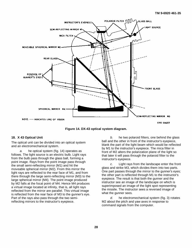
Figure 14. DX-43 optical system diagram.
18. X 43 Optical Unit
The optical unit can be divided into an optical systemand an electromechanical system.
a. he optical system (fig. 14) operates asfollows. The light source is an electric bulb. Light raysfrom the bulb pass through the glass ball, forming apoint image. Rays from the point image pass throughthe small semi-reflecting mirror (M1) and hit themoveable spherical mirror (M2). From this mirror thelight rays are reflected to the rear face of M1, and fromthere through the large semi-reflecting mirror (M3) to thelarge spherical mirror (M4). The point image producedby M2 falls at the focal point of M4. Hence M4 producesa virtual image located at infinity, that is, all light raysreflected from the mirror are parallel. This virtual imageis reflected from the rear face of M3 to the gunner's eye.Part of the rays also pass through the two semi-reflecting mirrors to the instructor's eyepiece.
b. he two polaroid filters, one behind the glassball and the other in front of the instructor's eyepiece,blank the part of the light beam which would be reflectedby M1 to the instructor's eyepiece. The mica filter infront of M2 alters the polarization plane of the light sothat later it will pass through the polaroid filter to theinstructor's eyepiece.
c. Light rays from the landscape enter the frontglass and strike M3, which divides them into two parts.One part passes through the mirror to the gunner's eyes;the other part is reflected through M1 to the instructor'seyepiece. The result is that both the gunner and theinstructor see an image of the landscape on which issuperimposed an image of the light spot representingthe missile. The instructor sees a reversed image ofwhat the gunner sees.
d. he electromechanical system (fig. 3) rotatesM2 about the pitch and yaw axes in response tocommand signals from the computer.
28

TM 9-6920-461-35
The yaw and pitch servomotors, through reductiongears, move the mirror and the two position pickoffs.The fixed voltage windings of the servomotors aresupplied with a constant 400 cps voltage. The controlwindings are supplied with a variable 400 cps voltage, 0-or 180-degree phase. The reference windings of thegenerators are connected in parallel and supplied with a400 cps voltage proportional to time. The outputs of themeasuring windings are fed back to the computersecond control amplifier. The measuring windingsproduce a voltage proportional to the reference windingvoltage (time) and to the motor speed (angularmovement of the spot), and therefore proportional to theangular velocity of the spot. R1 and R2 are supplied atthe ends with 12v 400 cps, and the center taps aregrounded. The voltage between the wiper and ground isproportional to the position of the light spot, and thephase indicates direction with respect to center position.Before firing, this voltage, in parallel with a TM 96920-461-35 voltage set by the initial position control, is
applied to the second control amplifier. The differencebetween the two represents position error. Whenamplified, it causes the servomotor to move the mirrorso as to cancel the error.
19. DX-44 Projector
The DX-44 projector, used for indoor training,projects on a screen a spot of light representing themissile. The projector can ble divided into an opticalsystem and an electromechanical system.a. The optical system of the DX-44 projector (fig. 15) issimpler than that of the DX-43 optical unit. The lightsource is an electric bulb.Light rays from the bulb pass through the diaphragm tothe fixed mirror and are reflected through the lens to themovable mirror. The image is reflected by the movablemirror out of the projector to the screen, which may befrom 10 to 30 feet away. The system is focused byadjusting the distance between the light source
Figure 15. DX-44 projector optical diagram.
29

TM 9-6920-461-35
and the fixed mirror. This is the same as varying thedistance between the source and the lens. Thediaphragm, which varies the size of the projected spot,is actuated by a galvanometer-type motor which isconnected in parallel with the lamp. Since the voltagesupplied to the lamp decreases with time (par. 16), thediaphragm gradually closes as time passes, and opensagain upon simulated missile explosion.
b. Electromechanical components of thecontrol channels are like those in DX-43 optical unit
(par. 18), except that the reduction gear ratios aredifferent. The principle of operation is exactly the same.
c. he regulated power supply (par. 17), ratherthan being a separate unit, is installed in the base of theprojector. For DX-44 use, there are two minor changesin the power supply. A power indicator lamp is added inparallel with one of the transformer windings, and aconnection is made from the power supply output aheadof the filter. These changes are shown on figure 12.
30

C 1 TM 96920-461-35
CHAPTER 3
MAINTENANCE INSTRUCTIONS
Section I. GENERAL
20. Tools and Equipment
Common tools and equipment used in maintainingthe simulators are authorized by tables of organizationand equipment or tables of distribution. No special toolsare authorized.
21. Cleaning
a. Clean rubber parts with soap and water.Apply a coating of powdered technical talcum topreserve the rubber.
b. Remove dust and lint from meter glass witha soft cloth or brush. Clean dust and lint fromcomponent boards, heat sinks, and electroniccomponents with a brush.
c. Wash meter glass with lens tissue paperlightly moistened with alcohol.
Section II. TROUBLESHOOTING
Note. Figures 16 through 25 areexploded views of the equipment,and figures 26 through 33 arecomponent locator views.
22. Testing AC Amplifiers (A4.5) (fig. 5)
Four identical ac amplifier modules - two secondcontrol amplifiers, one time channel servo amplifier, andone distance amplifier are used in the computer. Todetermine whether any ac amplifier is operatingcorrectly, measure with a VTVM the following voltages.The computer may be in either the ready or the firingcondition.
a. The 400 cps input voltage, measured acrossterminals l and 2, should vary from 0 to 100 millivolts.
b. The 400 cps output voltage, measuredacross terminals 6 and 9, should also vary from 0 to 100millivolts.
c. The dc supply voltages should be -16v atterminal 3 and -24v at terminal 5, both with respect toterminal 2.
23. Testing DC Amplifiers (A1.2) (fig. 4)
Two identical dc amplifier modules, the firstcontrol amplifiers, are used in the computer. Todetermine whether dc amplifier is operating correctly,measure with a VTVM the following voltages. Thecomputer should be in the ready condition.
a. The dc input voltage, measured at terminal1 with respect to terminal 2, should vary from 0 to +100millivolts.
b. The output voltages should vary from 0 to ±15V at terminal 8 with respect to terminal 2, and from 0to 15v 400 cps across terminals 6 or 7 and 2.
c. The dc supply voltage should be -22v atterminal 5 with respect to terminal 2.
d. The ac voltage should be 12v 400 cpsacross terminals 9 and 10.
24. Checking optical Unit or ProjectorPotentiometers
Check the optical unit or projector position pickoffpotentiometers as follows:
Caution: Never check these twopotentiometers with an ohmmeter,Never connect any measuring devicedirectly to the wiper contact ofpotentiometers. Always include thewiper protection resistor (470 ohms)in the circuit to be measured.
a. Deenergize the optical unit and disconnectfrom the cable which goes to the computer.
b. Set up AN/USM-117 oscilloscope foroperation. Set oscilloscope calibrate voltage to .4V.
c. Connect the oscilloscope .4 volt calibrateoutput to J-K1 pin U and W.
d. Connect the vertical input of theoscilloscope between J-K1 pin W and, for the yawpotentiometers, J-K1 pin P; for the pitch potentiometer,J-K1 pin T. Vary the potentiometer setting and observethe oscilloscope presentation. The potential should varyin amplitude from 0 to .4V as the potentiometer isrotated from minimum to maximum.
25. Computer Checks
a. If the computer fuze blows when power isapplied, disconnect the power supply at the computer,replace the fuze, and with the multimeter set to rangeRX1, check the resistance of
31

C 1 TM 9-6920-461-35
the computer 24v supply line. This check may be madefrom J-K1 pin 2 to J-K1 pin 1, with the power switch on.The resistance should be, with all plug-in modules inplace, 1.8 ohms or 60 ohms, depending on the polarityof the ohmmeter connection. If the resistance is zero,remove the modules one at a time and replace anydefective module. Resistance with all modules removedis 200 ohms. If this procedure does not localize thetrouble, check the insulation to chassis ground oftransistors Q-Y1, Q-Y2, Q-Y15 and Q-Y20. If there is noshort to ground, remove the transistors one at a time,test them, and replace any defective ones.
b. If the power lamp and circuit and the powersupply are good, but the lamp does not
glow when power is applied and the fuze does notblow, check the continuity of switch S1.
c. If the light spot remains stationary in eitherthe pitch or the yaw channel, make the following checks(indicated for the pitch channel ):
(1) If the spot responds to the initialposition control setting hut not to theinitial velocity control setting, checkvoltages of the velocity circuits and dcamplifiers (table 5). If the controlvoltage into the dc amplifier is zero,check switch S2 circuit to the controlstick. Check that relay B energizes.Check
Figure 16. Computer case exploded view.
32

TM 9-6920-461-35
Figure 17. Computer chassis partial exploded view.
the continuity of relay B, commutatorS-P4, and bus bar W. Check thecombined resistance of potentiometerR-P7 and its protective resistor andtheir 11v supply.
(2) If the spot responds to the initialvelocity control setting but not to the
initial position control setting, checkinput and output voltages of thesecond control (ac) amplifiers (table5). Check the position setting voltageand the position return voltage (table5).
33

TM 9-6920-461-35
Figure 18. Computer front panel exploded view
If the position return voltage isincorrect, check the cable and opticalunit circuit (table 3 or 4).
26. Troubleshooting Tables
a. Tables 2, 3, and 4 provide operationalchecks and troubleshooting procedures for the
computer, DX-43 optical unit, and DX-44 projector.b. Table 5 lists computer voltages at various
check points, with the computer in the ready and thefiring condition. Figures 3-7 are the computerschematics, and figures 19-25 are the parts locatordiagrams.
34

TM 9-6920-461-35
1--Screw 100223012--Cap 100224933--Connector 100224664--Gasket 100224275--Mounting plate6--Washer 100223857--Nut 100223688--Part of 39--Part of 3
10--Part of 311--Part of 312--Lock nut 1002236213--Transistor (Q--Y15) 1017327414--Screw 1002233815--Transistor support 1002323316--Insulator 1002243817--Screw 1002229418--Terminal board (TB--J7) 1017327119--Spacer 1002244920--Lock washer 1002237021--Nut 1002235222--Nut 10022355623--Washer 1002238624--Nut 1002235925--Transistor clip 1017324026--Screw 1002233527--Part of 4928--Part of 4929--Part of 4530--Part of 4531--Mounting plate32--Toggle switch 1002248833--Part of 3834--Gasket 1002240735--Part of 3736--Part of 3737--Indicator 10173249 and lamp 1017317438--Fuseholder 10173244 and gasket 1002240839--Fuse (2.5A) 1013454840--Part of 3841--Part of 3242--Part of 3243--Screw 1002230344--Cap 1002249245--Connector (J--K2) 1002246546--Gasket 1002243347--Screw 1002230348--Cap 1002249149--Connector (J--K1) 1002246450--Gasket 1002243251— Plate
Figure 18. Legend.
35
TM 9-6920-461-35
1--Part of 2, 29, 31, 32, 332--Dial w/knob 101732423--Part of 84--Part of 85--Index marker 100227386--Part of 57--Part of 58--Variable resistor 101731729--Switch
10--Switch11--Mounting bracket12--Part of 3013--Part of 3014--Terminal strip (TB-J8)15--Screw 1002229516--Lock washer 1002237117--Nut 1002235318--Variable resistor 1017317119--Variable resistor 1017317020--Counter 1017324521--Nut 1002235422--Lock washer 1002237223--Switch 1002248724--Part of 2325--Boot 1017324626--Gasket 1002241727--Cover 1017324728--Screw 1002230029--Knob 1002273730--Indicator 10173248 and lamp 1017317431--Knob 1017324132--Dial w/knob 1002273933--Dial w/knob 10173243
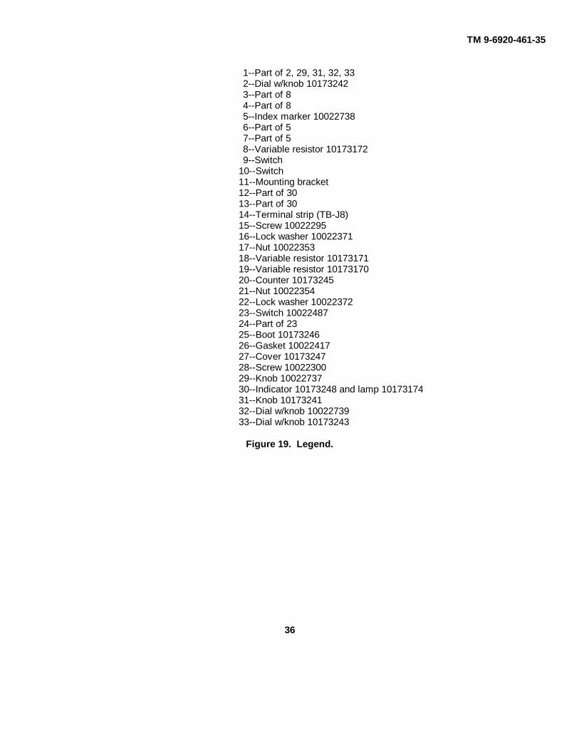
Figure 19. Legend.
36

TM 9-6920-461-35
Figure 19. Computer front panel exploded view.
37

TM 9-6920-461-35
Figure 20. Computer chassis partial exploded view.
38

TM 9-6920-461-35
1---Side panel 34--Parts group2--Relay 10178165 Terminal strip (TB--J4) 101732903--Screw 10022311 Insulator 100224344--Screw 10022302 Insulator 10224855--Screw 10022310 35--Parts group6--Screw 10022309 Screw 100223097--Screw 10022311 Nut 102235638--Spacer 10022452 Washer 10228849--Insulator 10022439 36--Nut 10022353
10--Lead support 101723 37--Washer 100223 7711--Transistor (Q--Y2) 10022261 38--Receptacle (J--K4) 1002246212--Screw 10022338 39--Spacer 1017325813--Receptacle 10022461 and spacer 10173259 40--Power supply 1017317614--Terminal strip (TB--J3) 10178269 A--Screw 1002228515--Nut 1002235316--Washer 1002271 B--Hold down plate17--Same as 13 C--Transformer 1002250118--Screw 10022296 D--Support19--Terminal strip (TB--J2 w/o components) 10173267 E--Connector 1002246020--Terminal strip (TB--J1 w/o components) 10173268 F--Washer 1002237721--Same as 13 G--Screw 1002229622--Same as 13 H--Capacitor (C2) 1002253323--Coil 10022509 J--Support24--Same as 13 K--Screw 1002229725--Same as 13 L--Terminal strip (TB--J6 w/o components)26--Receptacle 10022641-- and spacer 10173260 1017326527--Same as 26 M--Screw 1002229928--Washer 10022386 N--Spacer 1002244529--Sleeve 10022439 P--Collar30--Buss bar Q--Screw 1002229731--Spacer 10022453 R--Screw 1002228732--Nut, part of 2 41--Screw 1002229733--Washer, part of 2 42--Screw 10022299
Figure 20. Legend.
1--Screw 10022295 5--Screw 10022295 10--Screw 100223382--Printed circuit board 10173250 6--Cover 10173230 11--Connector 100224593--Spacer 10022446 7--Handle 10173232 12--Screw 100223264--Printed circuit board 10173251 8--Screw 10022324 13--Screw 10022824
9--BaseFigure 21. G0-1 generator exploded view.
39

TM 9-6920-461-35
1--Screw 10022295 8--Screw 100223242--Spacer 10022446 9--Base3--Screw 10022295 10--Screw 100223334--Printed circuit board 10173265 11--Connector 100224595--Screw 10022324 12--Screw 100223266--Cover 10173280 13--Printed circuit board 101732547--Handle 10173232
Figure 22. A1-2 amplifier exploded view.
40

TM 9-6920-461-35
1--Screw 10022319 14--Nut 100228582--Part of 4 15--Part of 163--Part of 4 16--Transistor (Q--Y6) 100222634--Transformer (T3) 17--Lug 100224675--Spacer 10022447 18--Screw 100223216--Part of 4 19--Screw 100222267--Printed circuit board 10173252 20--Connector 100224598--Screw 10022295 21--Screw 1002233339--Spacer 10022446 22--Base
10--Resistor (R20) 10022556 23--Screw 1002232411--Screw 10022295 24--Handle 1017323212--Screw 10022324 25--Cover 1017323013--Printed circuit board 10173253
Figure 23. G4-2 oscillator exploded view.
41

TM 9-6920-461-35
1--Cover 10178231 12--Screw 100223252--Screw 10022323 13--Insulating sleeve 100224403--Screw 10022295 14--Lug 100224714--Printed circuit board 10173257 15--Transistor 100222625--Spacer 10022448 16--Insulator 100224386--Plate 17--Transformer (T1) 100225027--Screw 10022304 18--Screw 100223048--Transformer (T2) 10022503 19--Case9--Printed circuit board 20--Handle 10173232
10--Screw 10022318 21--Lug 1002246811--Spacer key 10173262
Connector 10022458Spacer 10022736
Figure 14. A4-5 amplifier exploded view.
Figure 25. Legend.1--Handle 10022695 22--Screw 100226262--Screw 10022680 2B--Case bottom3--Case top 24--Lockwasher 100224684--Identification plate 25--Nut 100226675--Screw 10022622 26--Lug 100226246--Gasket 10022652 27--Lock washer 100224687--Choke (L1) 10022687 28--Nut 100226678--Washer 10022697 29--Fuseholder 101732449--Gasket 10022407 30--Transformer (T1) 1002269810--Nut 31--Rubber foot 1002269611--Fuse (F1) 10173169 32--Screw 1002262112--Gasket 10022408 3S--Screw 1002262618--Fuseholder cap 34--Screw 1002262514--Gasket 86--Screw 1002264215--Connector (J--K2) 10022687 86--Washer 1002267216--Screw 10022624 37--Nut 1002266817--Connector cap 10022667 88--Capacitor (C9) 1017819618--Connector cap 10022656 39--Cover19--Screw 10022624 40--Screw 1002262720--Connector 10022686 41--Relay 1002270221--Gasket 42--Screw 10022627
42

TM 9-6920-461-35
43--Printed circuit board 10022700 53--Washer 1002267744--Junction 54--Nut45--Screw 10022628 55--Diode 1002254346--Screw 10022635 56--Regulator 1002269947--Spacer 10022648 57--Diode 1002254348--Washer 58--Insulator 1002264949--Nut 59--Insulator 1002265050--Diode 10022269 60--Lug 1002262451--Sleeve 10022650 61--Washer 1002267752--Lug 10022689 62--Nut
Figure 25. Regulated power supply exploded view.
43

TM 9-6920-461-35
Figure 26. Computer chassis--locator view.
44

TM 9-6920-461-35
Figure 27. Front panel and switches--locator views.
45

TM 9-6920-461-35
Figure 28. Terminal strips--locator views.
46

TM 9-6920-461-35
Figure 29. G0-1 generator--locator view.
47

TM 9-6920-461-35
Figure 30. G4-2 oscillator--locator view.
48
TM 9-6920-461-35
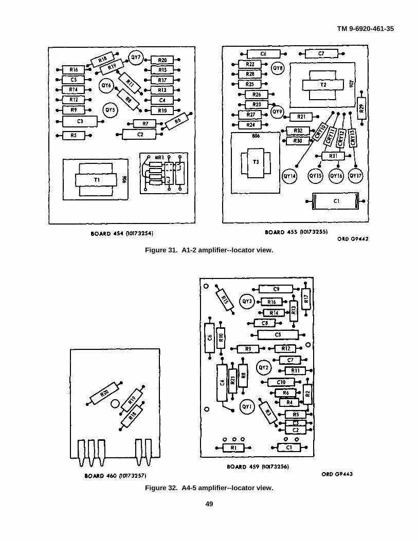
Figure 31. A1-2 amplifier--locator view.
Figure 32. A4-5 amplifier--locator view.
49
TM 9-6920-461-35
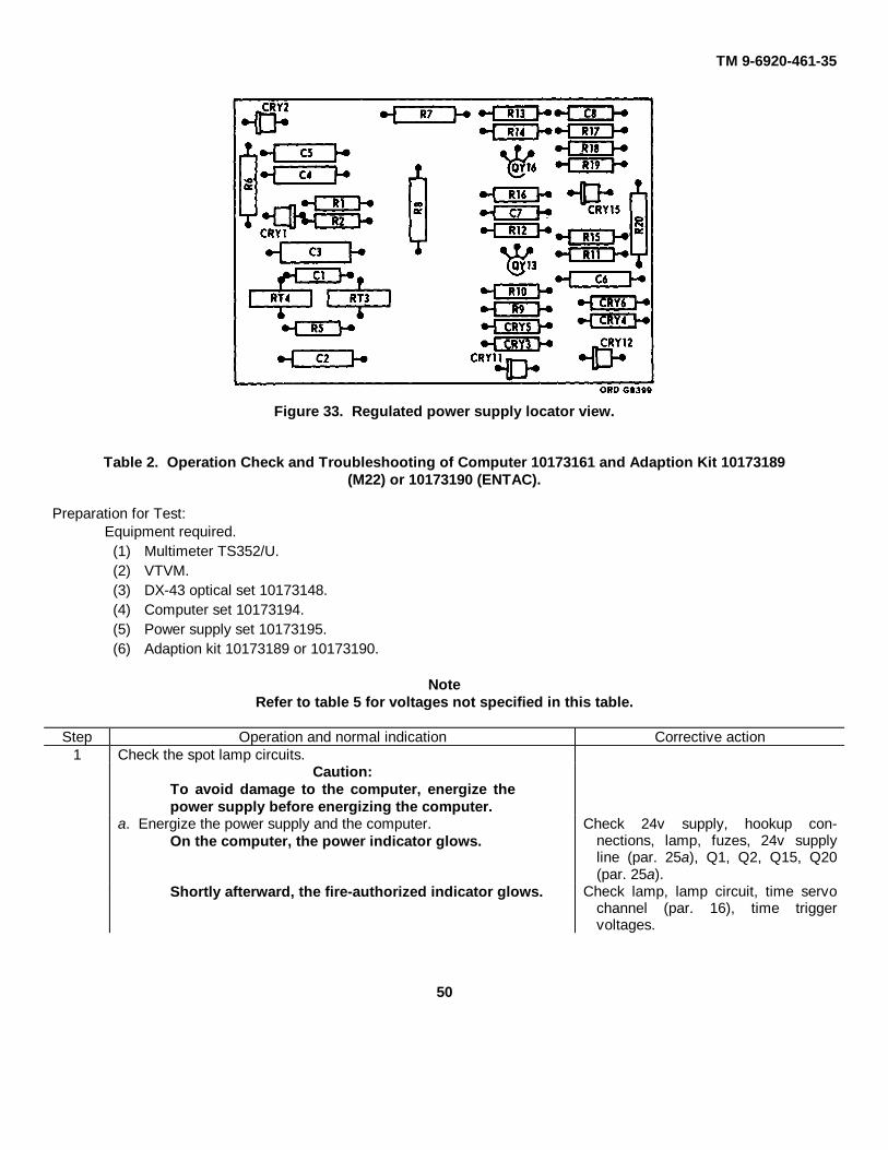
Figure 33. Regulated power supply locator view.
Table 2. Operation Check and Troubleshooting of Computer 10173161 and Adaption Kit 10173189(M22) or 10173190 (ENTAC).
Preparation for Test:Equipment required.
(1) Multimeter TS352/U.(2) VTVM.(3) DX-43 optical set 10173148.(4) Computer set 10173194.(5) Power supply set 10173195.(6) Adaption kit 10173189 or 10173190.
NoteRefer to table 5 for voltages not specified in this table.
Step Operation and normal indication Corrective action1 Check the spot lamp circuits.
Caution:To avoid damage to the computer, energize thepower supply before energizing the computer.
a. Energize the power supply and the computer.On the computer, the power indicator glows.
Check 24v supply, hookup con-nections, lamp, fuzes, 24v supplyline (par. 25a), Q1, Q2, Q15, Q20(par. 25a).
Shortly afterward, the fire-authorized indicator glows. Check lamp, lamp circuit, time servochannel (par. 16), time triggervoltages.
50

TM 9-6920-461-35C 1
Table 2. Operation Check and Troubleshooting of Computer 10173161 and Adaption Kit 10173189(M22) or 10173190 (ENTAC)--Continued.
Step Operation and normal indication Corrective action1 b. Set all four initial condition controls to zero and
Cont'd the spot brilliance control to midrange. Push thefire button.
The light spot is visible at instructor's and Check cable hookup, time servogunner's eyepieces. channel, time trigger, spot
brilliance control circuit voltages.Check relay E. Troubleshootoptical unit.
2 Check control of light spot movement.a. With controls set in 1b, observe the spot and
operate the control stick in pitch and yaw.The spot moves according to direction of Orient the stick correctly.stick movement.Light spot is controllable in both pitch Check continuity of computer-and yaw. optical unit cable. Check
alinement of connectors. Goto step 2c.
b. Move the stick first in pitch, then in yaw, whileobserving the spot for sensitivity of response.
Spot response is quick and overshoot Check timer amplifier inputminimum. and output voltages. Check
R-P3 resistance (5K) andsupply voltage (6v, 400 cps).
c. Initiate and observe several flights, varying theinitial position and initial velocity control settingsfor each flight, and operating the control stick.
Light spot conforms to initial position and Check continuity of computer-initial velocity control settings. optical unit cable.Light spot is controlled by the control Check stick supply voltages; ifstick. Ov, change power supply unit
31.200. Check control stickpotentiometers and circuitcontinuity.
d. Set the atmospheric condition control for gusts,initiate a flight, and observe the spot.
The spot shows the effect of crosswinds Check gust generator voltages.and turbulence in both pitch and yaw.
3 Check firing time, brilliance, and counter circuits.a. Set the firing time control to 20 seconds, initiate a
flight, and time the flight.Actual flight time is approximately 20 Check time channel measuringseconds. phase and error signal volt-
ages. Check that R23, on thetime channel servomotor, isnot shorted to ground.
51

TM 9-6920-461-35C 1
Table 2. Operation Check and Troubleshooting of Computer 10173161 and Adaption Kit 10173189 (M22)or 10173190 (ENTAC) – Continued
Step Operation and normal indication Corrective action3 b. Initiate a flight and observe the variation in brilliance
Cont'd of the light spot throughout the flight.The spot decreases in brilliance with time. Check light intensity control circuit
voltages (control signal max. Andmin. and Q-Y15 emitter max. Andmin.). If only the emitter voltageis incorrect, check relay contactA5 before replacing Q-Y15.
At the end of the flight the spot flashes Check relay contact K-A and relaymore brilliant E time delay circuit (R17-C8).At the end of the flight, the number-of- Check relay contacts K-B and K-Efirings counter advances by one number. and counter coil continuity (300
ohms).
Table 3. Operation Check and Troubleshooting of DX--43 Optical Unit 10173149
Preparation for Test:a. Equipment required.
(1) Multimeter TS352/U(2) Oscilloscope(3) DX-43 optical set 10173148(4) Computer set 10173194(5) Power supply set 10173195(6) Adaption kit 10173189
b. Connect the simulator as for normal operation.
Step Operation and normal indication Corrective action1 Check the spot-lamp circuit.
CAUTION:To avoid damage to the computer, energize thepower supply before energizing the computer.
a. Energize the power supply and the computer.The computer power indicator glows, and Replace indicator bulbs. Checkthen the fire-authorized indicator glows. power supply voltage. Check cable
hookup. Troubleshoot computer(table 2).
b. Set all four initial condition controls to zero and the spotbrilliance control to midrange. Push the fire button.
The light spot is visible at both instructor's Replace spot lamp bulb. Checkand gunner's eyepieces. continuity of bulb circuit. Check
continuity of optical unit-to-computercable. Troubleshoot computer.
52

TM 9-6920-461-35C 1
Table 3. Operation Check and Troubleshooting of DX-43 Optical Unit 10173149 -- Continued.
Step Operation and normal indication Corrective action2 Check the control circuits.
a. While observing the spot during flight time, operatethe control stick in pitch and yaw.
Control stick movement causes movement Check continuity of opticalof the spot in pitch and yaw. unit-to-computer cable, fixed
phase circuit, and controlwinding circuit of servo-motor in the faulty channel.
b. Operating the control stick in pitch, observe thespot. Check for correct connector
Spot movements are controlled by stick alinement at computer.movements. Spot response is quick and Check continuity of cable,overshoot minimum. motor control winding, and
generator reference windingin the pitch channel. Trouble-shoot computer.
c. Operating the control stick in yaw, observe the spot.Same as b above.
3 Check the initial position circuit. Same as b above, yaw channel.a. Set the yaw initial position control to zero; initiate
and observe several flights, setting the pitchinitial position control to a different position foreach flight.
The spot position conforms to the pitch Check continuity of cable.initial position control setting. Check position pickoff po-
tentiometer in pitch channel(Par. 24). Troubleshootcomputer.
b. Set the pitch initial position control to zero; initiateand observe several flights, setting the yaw initialposition control to a different position foreach flight.
The spot position conforms to the yaw Same as a above, yaw channel.initial position control setting.
53

TM 9-6920-461-35C 1
Table 4. Operation Check and Troubleshooting of DX-44 Projector 10173193 (excluding integral power supply)
Preparation for Test:a. Equipment required:
(1) Multimeter TS352/U(2) Oscilloscope(3) DX-44 projector set 10173188(4) Computer set 10173194(5) Adaption kit 10173189
b. Connect the simulator as for normal operation.
Step Operation and normal indication Corrective action1 Check the spot-lamp circuit.
CAUTION:To avoid damage to the computer, energize thepower supply before energizing the computer.
a. Energize the power supply and the computer.The computer power indicator glows, and Replace indicator bulbs. Checkthen the fire-authorized indicator glows. power supply voltage. Check cable
hookup. Troubleshoot computer(table 2).
The projector control panel light glows. Replace bulb. Check fuse, connectorsat computer, 24v or line cableshort, bulb circuit or C10 openor short. Check for open supplycable.
b. Set all four initial condition controls to zero and the spotbrilliance control to midrange. Push the fire button.
The light spot is visible on the projection Position lamp correctly. Replacescreen. bulb. Check continuity of bulb
circuit and projector-computercable. Troubleshoot computer.
2 Check the control circuits.a. While observing the spot during flight time, operate the
control stick in pitch and yaw.Control stick movement causes movement Check continuity of projector-computerof the spot in pitch and yaw. cable, fixed phase circuit
and control winding circuit ofservomotor in the faulty channel.
b. Operating the control stick in pitch, observe the spot.
Spot movements are controlled by stick Check for correct connector alinementmovements. Spot response is quick and at computer. Check continuityovershoot minimum. of cable, motor generator
reference winging in the pitchchannel. Troubleshoot computer.
54

TM 9-6920-461-35C 1
Table 4. Operation Check and Troubleshooting of DX-44 Projector 10173193 (excluding integral potter supply) -- Continued
Step Operation and normal indication Corrective action2 c. Operating the control stick in yaw, observe the spot.
Cont'dSame as b above. Same as b above, yaw channel.
3 Check the initial position circuit.a. Set the yaw initial position control to zero; initiate and
observe several flights, setting the pitch initial positioncontrol to a different position for each flight.
The spot position conforms to the pitch Check continuity of cable. Checkinitial position control setting. position pickoff potentiometer in
pitch channel (par. 24). Trouble-shoot computer.
b. Set the pitch initial position control to zero; initiate andobserve flights, setting the yaw initial position controlto a different position for each flight.
The spot position conforms to the pitch Same as a above, yaw channel.initial position control setting.
55

TM 9-6920-461-35C 1
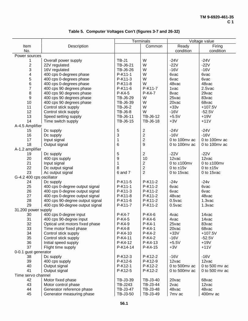
Table 5. Computer Voltages (figures 3-7 and 26-32)
Table 5 contains a list of normal voltages in the computer circuits with the computer in the ready and firingconditions. Tolerance on all voltages is ± 100%.
Preparation for test:a. Equipment required.
(1) Power supply set 10173195.(2) VTVM.(3) Control stick 10173179 or 10173184.
b. Remove the computer as shown in figure 34.c. Connect the equipment as shown in figure 34.
Figure 34. Test hookup -- computer voltages.
d. When measuring voltages in the firing condition, let the control stick stand at zero pitch and yaw commands. Set theTIME OF FLIGHT control to 29 seconds, and fire the computer as required. The computer is in the firing condition whenthe FIRE OFF indicator is out.
NoteAll ac voltages are 400 cycles per second.
56
TM 9-6920-461-35C 1
Table 5. Computer Voltages Con't (figures 3-7 and 26-32)
Terminals Voltage valueItem Description Common Ready FiringNo. condition condition
Power sources1 Overall power supply TB-J1 W -24V -24V2 22V regulated TB-J6-21 W -22V -22V3 16V regulated TB-J6-26 W -16V -16V4 400 cps 0-degrees phase P-K11-1 W 6vac 6vac5 400 cps 0-degrees phase P-K11-3 W 6vac 6vac6 400 cps 0-degrees phase P-K11-8 W 48vac 48vac7 400 cps 90 degrees phase P-K11-6 P-K11-7 1vac 2.Svac8 400 cps 90 degrees phase P-K4-5 P-K4-7 8vac 29vac9 400 cps 90 degrees phase TB-J6-29 W 25vac 83vac
10 400 cps 90 degrees phase TB-J6-39 W 20vac 68vac11 Control stick supply TB-J6-2 W +33v +107.5V12 Control stick supply TB-J6-8 W -16V -52.5V13 Speed setting supply TB-J6-11 TB-J6-12 +5.5V +19V14 Time switch supply TB-J6-15 TB-J6-18 +3V +11V
A-4.5 Amplifier15 Dc supply 5 2 -24V -24V16 Dc supply 3 2 -16V -16V17 Input signal 1 2 0 to 100mv ac 0 to 100mv ac18 Output signal 6 9 0 to 100mv ac 0 to 100mv ac
A-1.2 amplifier19 Dc supply 5 2 -22V -22V20 400 cps supply 9 10 12vac 12vac21 Input signal 1 2 0 to ±100mv 0 to ±100mv22 Dc output signal 8 2 0 to ±15v 0 to ±15v23 Ac output signal 6 and 7 2 0 to 15vac 0 to 15vac
G-4.2 400 cps oscillator24 Dc supply P-K11-5 P-K11-2 -24v -24v25 400 cps 0-degree output signal P-K11-1 P-K11-2 6vac 6vac26 400 cps 0-degree output signal P-K11-3 P-K11-2 6vac 6vac27 400 cps 0-degree output signal P-K11-8 P-K11-2 48vac 48vac28 400 cps 90-degree output signal P-K11-6 P-K11-2 0.5vac 1.3vac29 400 cps 90-degree output signal P-K11-7 P-K11-2 0.5vac 1.3vac
31.200 power supply30 400 cps 0-degree input P-K4-7 P-K4-6 4vac 14vac31 400 cps 90-degree input P-K4-5 P-K4-6 4vac 14vac32 Optical unit motors fixed phase P-K4-9 P-K4-1 25vac 83vac33 Time motor fixed phase P-K4-8 P-K4-1 20vac 68vac34 Control stick supply P-K4-10 P-K4-2 +33V +107.5V35 Control stick supply P-K4-11 P-K4-2 -16V -52.5V36 Initial speed supply P-K4-12 P-K4-13 +5.5V +19V37 Flight time supply P-K14-14 P-K4-15 +3V +11V
0-0.1 gust generator38 Dc supply P-K12-3 P-K12-2 -16V -16V39 400 cps supply P-K12-6 P-K12-9 12vac 12vac40 Output signal P-K12-1 P-K12-2 0 to 500mv ac 0 to 500 mv ac41 Output signal P-K12-5 P-K12-2 0 to 500mv ac 0 to 500 mv ac
Time servo channel42 Motor fixed phase TB-J3-39 TB-J3-40 20vac 68vac43 Motor control phase TB-J243 TB-J3-44 2vac 12vac44 Generator reference phase TB-J3-47 TB-J3-48 48vac 48vac45 Generator measuring phase TB-J3-50 TB-J3-49 7mv ac 400mv ac
56.1

TM 9-6920-461-35C 1
Table 5. Computer Voltages -- Cont’d
Terminals Voltage valueItem Description Common Ready FiringNo. condition condition
46 Reverse control voltage TB-J3-15 W 60mv ac 6vac*47 Direct control voltage TB-J3-17 W 0 6vac48 Generator return TB-J3-19 W 10mv ac 240mv ac49 Time amplifier input TB-J3-16 W 2.5mv ac 25mv acTime trigger50 R-P1 supply TB-J3-36 TB-J3-38 -3V -11V51 R-P5 supply TB-J3-35 TB-J3-7 -3V -11V52 Q-Y13, Q-Y14 emitters TB-J1-42 W -0.35V -2.1V53 Q-Y14 emitter-collector TB-J1-38 TB-J1-42 -14.5V -12.5V54 Q-Y13 emitter-collector TB-J1-37 TB-J1-41 0 055 Control signal TB-J1-40 TB-J-42 -2.3V to 0 -9V to +0.2VDistance amplifier56 Control signal TB-J3-5 W 0.3vac 0.3 to 5.8vac57 Output signal TB-J3-3 W 3.3vac 3.3 to 6.8vac(These two signals vary linearly with time when the computer is in the firing condition.)
Spot brilliance circuit58 Control signal:
Max. brilliance TB-J3-30 W 0 -22V to -15.5VMin. brilliance TB-J3-30 W 0 -22V to -5V
59 Q-Y15 emitter:Max. brilliance Q-Y15-E W 0 -21V to -15VMin. brilliance Q-Y15-E W 0 -21V to -5V
Yaw speed channel60 Stick signal TB-J1-19 W 0 to ±0.65V 0 to ± 1.7V61 Speed setting signal TB-J1-21 W 0 to ±2.7V 0 to ± 9.6V62 Output signal TB-J1-25 W 0 to ±1.5V 0 to ± 15V63 Output signal P-K8-7 W 0 to 1.7vac 0 to 17vac64 Input signal TB-J1-28 W 0 to ± 5mv 0 to ±100mvPitch speed channel65 Stick signal TB-J2-19 W 0 to ± 0.4V 0 to ± 1.2V66 Speed setting signal TB-J2-21 W 0 to ± 2.7V 0 to ± 9.5V67 Output signal TB-J2-25 W 0 to ± 1.5V 0 to ± 15V68 Output signal P-K9-6 W 0 to 1.7vac 0 to 17vac69 Input signal TB-J2-28 W 0 to ± 5mv 0 to ± 100mvYaw position channel70 Gust signal TB-J1-3 W 0 0 to 500mv ac71 Speed input signal TB-J1-5 W 0 0 to 17vac72 Position setting signal TB-J1-7 W 0 to 6vac 073 Position return signal TB-J1-9 W 0 to 6vac 074 Generator return signal TB-J1-11 W 0 0 to 1vac75 Output signal P-K5-6 P-K6-9 0 0 to 100vac76 Input signal TB-J1-12 W 0 0 to 100mv acPitch position channel77 Gust signal TB-J2-3 W 0 0 to 500mv ac78 Speed input signal TB-J2-5 W 0 0 to 17vac79 Position setting signal TB-J2-7 W 0 to 6vac 080 Position return signal TB-J2-9 W 0 to 6vac 081 Generator return signal TB-J2-11 W 0 0 to 1vac82 Output signal P-K6-6 P-K6-9 0 0 to 100vac83 Input signal TB-J2-12 W 0 0 to 100mv ac*During return to zero only. Voltage is zero during firing.
57

TM 9-6920-461-35
Section III. REPAIR
27. GeneralThis section contains special instructions for
disassembly and assembly and other repair procedures.Most repair requires no special procedures, but iscompleted by following good general practices. Figures16-25 show disassembled views.
28. Purging the DX-43 Optical UnitFollowing any repair during which the sealed
DX-43 optical head has been opened, purge the unit asfollows.
a. Make sure there are no water droplets on anyinside surfaces of the unit.
b. Seal the unit, but leave the screws securing thecover loose, and insert a wooden spacer block about 1/4inch thick at one side of the cover.
c. Assemble the purging equipment as shown infigures 35 and 36, but do not connect it to the opticalhead yet.
d. Flush the purging equipment with nitrogen for afew seconds.
e. Remove the screw sealing the purging inlet portand connect the purging equipment to the optical head(fig. 36).
f. Set the regulator for a flow gage reading of 15-1/2 liters per minute, and maintain this flow for one hour.
Figure 35. DX-43 nitrogen purge system.
g. At the end of one hour, close the cylinder valveand the regulator.
h. Disconnect the purging equipment from theoptical head.
i. Replace the purging inlet screw, remove thespacer block, and tighten the cover on the optical head.
Figure 36. DX-43 nitrogen purge hookup to optical unit.
58

TM 9-6920-461-35
1--Cylinder assembly 101728032--Regulator 101728043--Preformed packing 5330-580-17264--Brass tube fitting 101728056--Brass tee 101728066--Pressure relief valve 101728077--Brass hose connection 10172808 (3)8--Hose clamp 10172811 (4)9--Rubber hose 10172809 (2)10--Flow gage 1017281011--Inlet fitting 10172812
Figure 36. Legend.
59

TM 9-6920-461-35
APPENDIX
REFERENCES
1. Publications IndexesConsult the following indexes frequently for latest changes or revisions of references given in this appendix and for
new publications relating to materiel covered in this technical manual.
Index of Administrative Publications ..................................................................................... DA Pam 310-1Index of Army Motion Pictures, Film Strips, Slides, and Phono-Recordings .......................... DA Pam 108-1Index of Blank Forms ........................................................................................................... DA Pam 310-2Index of Graphic Training Aids and Devices . ........................................................................ DA Pam 310-5Index of Tables of Organization and Equipment, Tables of Organization, Type Tables of
Distribution, and Tables of Distribution, and Tables of Allowances ..................................... DA Pam 310-7Index of Technical Manuals, Technical Bulletins, Supply Bulletins, Lubrication Orders, and
Modification Work Orders .................................................................................................. DA Pam 310-4Index of Training Publications ............................................................................................... DA Pam 310-3Index of Supply Manuals, Ordnance Corps ........................................................................... DA Pam 310-29
2. Related ENTAC and M22 PublicationsOperator's and Organizational Maintenance Manual: Guided Missile Training Sets DX-43
and DX-44 (ENTAC Antitank Guided Missile System and M-22 Guided Missile LauncherHelicopter Armament Subsystem) ........................................................................................ TM 9-6920-461-12
Direct Support, General Support, and Depot Maintenance, Repair Parts and Special ToolLists: Guided Missile Training Sets DX-43 and DX-44 .......................................................... TM 9-6920-461-35P
3. Forms and RecordsIn addition to the forms required by the Department of the Army Equipment Record System (TM 38-750), the following
forms pertain to this materiel:
Recommended Changes to DA Technical Manual, Parts Lists, or Supply Manual 7, 8, or 9 ....... DA Form 2028Report of Damaged or Improper Shipment ................................................................................ DD Form 6Request for Issue or Turn-In ...................................................................................................... DD Form 1546Requisition for Initial Distribution of Distribution of Publications and Blank Forms ..................... DA Form 12-32Requisition for Publications and Blank Forms............................................................................. DA Form 17
4. Miscellaneous PublicationsArmy Equipment Record System and Procedures: Operation TAPER ....................................... TM 38-750Army Safety Program ................................................................................................................ AR 385-10Authorized Abbreviations and Brevity Codes ............................................................................. AR 320-50Cleaning of Ordnance Materiel .................................................................................................. TM 9-208-1First Aid for Soldiers .................................................................................................................. FM 21-11Introduction ............................................................................................................................... ORD 1Ordnance Direct Support Service .............................................................................................. FM 9-3Ordnance General and Depot Support Service .......................................................................... FM 9-4Safety: Accident Reporting and Records ................................................................................... AR 385-40Solder and Soldering ................................................................................................................. TB SIG 222
61

TM 9-6920-461-35
By Order of the Secretary of the Army:
HAROLD K. JOHNSONGeneral, United States Army,
Chief of Staff.
Official:J. C. LAMBERT
Major General, United States Army,The Adjutant General.
Distribution:To be distributed in accordance with DA Form 1231, requirements for Field Maintenance instruction for G.M.L.-M22
Helicopter and DA Form 1242, Section II (Unclas) requirements for ENTAC, TM, Test Equipment (Ord).
U. S. GOVERNMENT PRINTING OFFICE: 1966__754442/80


The Metric System and Equivalents
Linear Measure Liquid Measure
1 centiliter = 10 milliters = .34 fl. ounce1 centimeter = 10 millimeters = .39 inch 1 deciliter = 10 centiliters = 3.38 fl. ounces1 decimeter = 10 centimeters = 3.94 inches 1 liter = 10 deciliters = 33.81 fl. ounces1 meter = 10 decimeters = 39.37 inches 1 dekaliter = 10 liters = 2.64 gallons1 dekameter = 10 meters = 32.8 feet 1 hectoliter = 10 dekaliters = 26.42 gallons1 hectometer = 10 dekameters = 328.08 feet 1 kiloliter = 10 hectoliters = 264.18 gallons1 kilometer = 10 hectometers = 3,280.8 feet
Square MeasureWeights
1 sq. centimeter = 100 sq. millimeters = .155 sq. inch1 centigram = 10 milligrams = .15 grain 1 sq. decimeter = 100 sq. centimeters = 15.5 sq. inches1 decigram = 10 centigrams = 1.54 grains 1 sq. meter (centare) = 100 sq. decimeters = 10.76 sq. feet1 gram = 10 decigram = .035 ounce 1 sq. dekameter (are) = 100 sq. meters = 1,076.4 sq. feet1 decagram = 10 grams = .35 ounce 1 sq. hectometer (hectare) = 100 sq. dekameters = 2.47 acres1 hectogram = 10 decagrams = 3.52 ounces 1 sq. kilometer = 100 sq. hectometers = .386 sq. mile1 kilogram = 10 hectograms = 2.2 pounds1 quintal = 100 kilograms = 220.46 pounds Cubic Measure1 metric ton = 10 quintals = 1.1 short tons
1 cu. centimeter = 1000 cu. millimeters = .06 cu. inch1 cu. decimeter = 1000 cu. centimeters = 61.02 cu. inches1 cu. meter = 1000 cu. decimeters = 35.31 cu. feet
Approximate Conversion Factors
To change To Multiply by To change To Multiply by
inches centimeters 2.540 ounce-inches Newton-meters .007062feet meters .305 centimeters inches .394yards meters .914 meters feet 3.280miles kilometers 1.609 meters yards 1.094square inches square centimeters 6.451 kilometers miles .621square feet square meters .093 square centimeters square inches .155square yards square meters .836 square meters square feet 10.764square miles square kilometers 2.590 square meters square yards 1.196acres square hectometers .405 square kilometers square miles .386cubic feet cubic meters .028 square hectometers acres 2.471cubic yards cubic meters .765 cubic meters cubic feet 35.315fluid ounces milliliters 29,573 cubic meters cubic yards 1.308pints liters .473 milliliters fluid ounces .034quarts liters .946 liters pints 2.113gallons liters 3.785 liters quarts 1.057ounces grams 28.349 liters gallons .264pounds kilograms .454 grams ounces .035short tons metric tons .907 kilograms pounds 2.205pound-feet Newton-meters 1.356 metric tons short tons 1.102pound-inches Newton-meters .11296
Temperature (Exact)
°F Fahrenheit 5/9 (after Celsius °Ctemperature subtracting 32) temperature

PIN: 010387-000

This fine document...
Was brought to you by me:
Liberated Manuals -- free army and government manuals
Why do I do it? I am tired of sleazy CD-ROM sellers, who take publicly available information, slap “watermarks” and other junk on it, and sell it. Those masters of search engine manipulation make sure that their sites that sell free information, come up first in search engines. They did not create it... They did not even scan it... Why should they get your money? Why are not letting you give those free manuals to your friends?
I am setting this document FREE. This document was made by the US Government and is NOT protected by Copyright. Feel free to share, republish, sell and so on.
I am not asking you for donations, fees or handouts. If you can, please provide a link to liberatedmanuals.com, so that free manuals come up first in search engines:
<A HREF=http://www.liberatedmanuals.com/>Free Military and Government Manuals</A>
– SincerelyIgor Chudovhttp://igor.chudov.com/
– Chicago Machinery Movers