tm manual key to program icons overview …€¦ · key to program icons overview overview...
TRANSCRIPT

CALCOMMSTM Manual
CAL ControlsTemperature Controllers
CAL ControlsTemperature Controllers
CAL 3300 and 9300Autotune Temperature
Controllers
CAL Controls LtdBury Mead Road, Hitchin, Herts, SG5 1RT. UK
Tel: + 44 (0)1462-436161 Fax: + 44 (0)1462-451801email: [email protected]
http://www.cal-controls.com
CAL Controls Inc1580 S.Milwaukee Avenue, Libertyville, IL 60048. USA
Tel: (847) 680-7080 Fax: (847) 816-6852
33011/1/1297
INDEX
KEY TO PROGRAM ICONSOVERVIEW (inside front cover)INSTALLATION/CABLING
RS232 1RS485 2Termination resistors 3Bias resistors 4RS232/RS485 features 5
INSTRUMENT COMMS SETTINGS 6CONFIGURING INSTRUMENT COMMS SETTINGS 7-8INSTALLING CALCOMMSTM SOFTWARE 9-10GETTING STARTED 11CALCOMMSTM INSTRUMENT SCREENS 12PC COM PORT SETTINGS 13-14INSTRUMENT PARAMETER CONFIGURATIONSOFTWARE ALARMS 15SETPOINT ADJUSTMENT 16INSTRUMENT CLONING 17SAVING SETTINGS TO FILE 18SECURITY LOCKOUTS 19-20LOGGING AND CHARTING 21-24LOG ON CHANGE 25-26EXPORTING LOG FILES 27TROUBLE SHOOTING 28GLOSSARY OF TERMS 29-30NOTES 31-32
In
de
x

CALCOMMSTM Manual
CAL ControlsTemperature Controllers
CAL ControlsTemperature Controllers
CAL 3300 and 9300Autotune Temperature
Controllers
CAL Controls LtdBury Mead Road, Hitchin, Herts, SG5 1RT. UK
Tel: + 44 (0)1462-436161 Fax: + 44 (0)1462-451801email: [email protected]
http://www.cal-controls.com
CAL Controls Inc1580 S.Milwaukee Avenue, Libertyville, IL 60048. USA
Tel: (847) 680-7080 Fax: (847) 816-6852
33011/1/1297
INDEX
KEY TO PROGRAM ICONSOVERVIEW (inside front cover)INSTALLATION/CABLING
RS232 1RS485 2Termination resistors 3Bias resistors 4RS232/RS485 features 5
INSTRUMENT COMMS SETTINGS 6CONFIGURING INSTRUMENT COMMS SETTINGS 7-8INSTALLING CALCOMMSTM SOFTWARE 9-10GETTING STARTED 11CALCOMMSTM INSTRUMENT SCREENS 12PC COM PORT SETTINGS 13-14INSTRUMENT PARAMETER CONFIGURATIONSOFTWARE ALARMS 15SETPOINT ADJUSTMENT 16INSTRUMENT CLONING 17SAVING SETTINGS TO FILE 18SECURITY LOCKOUTS 19-20LOGGING AND CHARTING 21-24LOG ON CHANGE 25-26EXPORTING LOG FILES 27TROUBLE SHOOTING 28GLOSSARY OF TERMS 29-30CAL CONTACT INFORMATION 32
In
de
x

OVERVIEWKey to Program Icons
Ov
er
vi
ew
CALCOMMSTM is a graphic WINDOWSTM based softwarepackage designed for PC supervision of CAL Model 3300and Model 9300 controllers. It offers the capability ofremote adjustment, instrument configuration, cloning, savingand retrieving instrument settings to files together withlogging and charting in real time.
Communication uses the MODBUS® protocol via either afully isolated RS232 or RS485 link depending on the numberof instruments and the transmission distances involved in theapplication.
PC Requirements
To gain the full benefit of CALCOMMS software, it isrecommend that the PC is fitted with a Pentium processorand is running WINDOWS 95 or Windows NT programs. Aminimum of 16 Mb RAM is recommended to run theprogram, together with enough free hard disc space tomeet logging requirements.
This manual assumes that a mouse or other pointing devicewill be employed, but alternatively or in an emergency thestandard WINDOWS key convention can be used to operateor close the program.
Because the controllers are “stand alone” they do not needPC supervision for their normal function, and will continue tocontrol the process unaffected by failure of any part of thecommunications loop.
Ke
y
to
P
ro
gr
am
I
co
ns
Change comms settings &start monitoring
Toggle Modbus commsde-bug window
Add new instrument 3300
Add new instrument 9300
Arrange instruments in grid
Make instruments larger
Make instruments smaller
Set security locks
Add new chart recorder
Close program
Create new file Print chart recorder
Scroll chart up 100%
Scroll chart up 10%
Find chart zero
Scroll chart down 10%
Scroll chart down 100%
Expand verticle scaling range
Decrease verticle scaling range
Increase time/division
Decrease time/division
Open existing file
Export file in text format
Select units to record
Toggle grid density
Select background colour
Select primary grid colour
Select grid colour
Make chart bigger
Make chart smaller
Copyright CAL Controls Ltd. 1997
Not to be reproduced without prior written permission fromCAL Controls Ltd. Whilst every effort has been made to ensurethe accuracy of the specifications contained in this manual,due to our policy of continuous development, CAL Control Ltd.reserves the right to make changes without prior notice.

OVERVIEWKey to Program IconsO
ve
rv
ie
w
CALCOMMSTM is a graphic WINDOWSTM based softwarepackage designed for PC supervision of CAL Model 3300and Model 9300 controllers. It offers the capability ofremote adjustment, instrument configuration, cloning, savingand retrieving instrument settings to files together withlogging and charting in real time.
Communication uses the MODBUS® protocol via either afully isolated RS232 or RS485 link depending on the numberof instruments and the transmission distances involved in theapplication.
PC Requirements
To gain the full benefit of CALCOMMS software, it isrecommend that the PC is fitted with a Pentium processorand is running WINDOWS 95 or Windows NT programs. Aminimum of 16 Mb RAM is recommended to run theprogram, together with enough free hard disc space tomeet logging requirements.
This manual assumes that a mouse or other pointing devicewill be employed, but alternatively or in an emergency thestandard WINDOWS key convention can be used to operateor close the program.
Because the controllers are “stand alone” they do not needPC supervision for their normal function, and will continue tocontrol the process unaffected by failure of any part of thecommunications loop.
Ke
y
to
P
ro
gr
am
I
co
ns
Change comms settings &start monitoring
Toggle Modbus commsde-bug window
Add new instrument 3300
Add new instrument 9300
Arrange instruments in grid
Make instruments larger
Make instruments smaller
Set security locks
Add new chart recorder
Close program
Create new file Print chart recorder
Scroll chart up 100%
Scroll chart up 10%
Find chart zero
Scroll chart down 10%
Scroll chart down 100%
Expand verticle scaling range
Decrease verticle scaling range
Increase time/division
Decrease time/division
Open existing file
Export file in text format
Select units to record
Toggle grid density
Select background colour
Select primary grid colour
Select grid colour
Make chart bigger
Make chart smaller
Copyright CAL Controls Ltd. 1997
Not to be reproduced without prior written permission fromCAL Controls Ltd. Whilst every effort has been made to ensurethe accuracy of the specifications contained in this manual,due to our policy of continuous development, CAL Control Ltd.reserves the right to make changes without prior notice.

1 2 3 4 5 6 7 8
9 10 11 12 13 14 15 16
3300/9300rear terminal
1 5
6 9
PC Com 1DB-9 Pin
Tx
Rx
Gnd
COM port
CAL 9300
In
st
al
la
ti
on
/C
ab
li
ng
Installation/Cabling
1
RS-232 Is the standard most widely used for interfacingperipherals to PC's and is designed for serialcommunications with single instrument up to a distancesof 15 metres, in a low electrical noise environment.Connection is via a screened two core cable where thevoltage signal on each line is referenced to the screenwhich is grounded. Most PC's have one or two RS-232compatible ports fitted as standard.
RS232 Connections
Port

In
st
al
la
ti
on
/C
ab
li
ng
Installation/Cabling
2
Tx Rx (+)
1 2 3 4 5 6 7 8
9 10 11 12 13 14 15 16
Toadditional
units
1 2 3 4 5 6 7 8
9 10 11 12 13 14 15 16
3300/9300unit 2
Tx Rx (-)
3300/9300unit 1
Gnd
Tx Rx (+)
Tx Rx (-)
Gnd
Daisy chained connections
Connections if PC 485 card used
To RS 485 InterfaceEither plug in board or
separate converter
Note:Where separate RS 485interface is used, refer tomanufacturers instructions forconnection details
ToRS 485
interface
CAL 3300CAL 3300
CAL 3300CAL 3300
COM port
RS485 Connections
RS-485 Is a half duplex serial communications link and is thestandard most commonly used for industrial applications dueto it's high noise immunity and multi-drop capability. Itenables a PC to communicate with up to 32 instrumentsover distances up to 1200 metres, and requires the additionof an RS-485 interface card, or a separate RS-232/485converter.

In
st
al
la
ti
on
/C
ab
li
ng
Installation/Cabling
3
Termination resistors
–
120Ω
Tx
Rx
+
+
–
+–+–
TxRx +–
+–
TxRx +–
+–
TxRx
120Ω
Instrument 1 Instrument 2 Instrument ‘N’
Each RS485 interface has specific connection andtermination biasing requirements which will be detailed intheir installation instructions. The general principles are asfollows.
Terminations Because each wire is a transmission line, itmust be properly terminated to prevent reflections. Wheremultiple instruments are daisy-chained together, a 120 ohmterminating resistor should be fitted at the connection tothe PC and to the last instrument in the chain.

In
st
al
la
ti
on
/C
ab
li
ng
Installation/Cabling
4
Bias resistors
–
Tx
Rx
+
+
–
+–+–
TxRx +–
+–
TxRx +–
+–
TxRx
Instrument 1 Instrument 2 Instrument ‘N’
+5V620Ω
-5V620Ω
Bias resistors When transmission lines are not transmitting,they remain in an indeterminate state which can allowreceivers to receive invalid data bits due to electrical noiseon the cable. To prevent this, the the lines should be forced
into a known state by fitting two 620 ohm bias resistors toone point (node).
If an RS-485 interface card is being fitted to the PC,separate bias resistors may not be needed because theymay already be fitted to the card. Check the manufacturersspecification.

In
st
al
la
ti
on
/C
ab
li
ng
Installation/Cabling
5
For a continually updated list of recommended RS-485interface cards, contact CAL.
FeatureType of transmission lines Unbalanced
1 32
321
15M
19.2Kb/sec 19.2Kb/sec
+/- 25V + 12 to - 7V
1200M
Differential
Maximum number of drivers
Maximum number of receivers
Maximum cable length
Maximum data rate
Maximum CMV
RS232 RS485
Table lists the features of both RS-232 and RS-485standards.Cable To ensure data integrity over long transmissiondistances, it is recommended that good quality RS-485 cableis used.
Recommended: RS485: Belden 9841, RS232: Belden 9501available from most leading distributors, and stocked byCAL.

In
st
ru
me
nt
C
om
ms
S
et
ti
ng
sInstrument Comms Settings
6
Immediately after power-up, both instrument, and PC commssettings need to be made compatible before communicationbetween them is possible. Instrument defaults are shownbelow together with the available options.
ADDR (Address) This is a uniqueidentification number that must be allocated to each instrument connected to the network.Default =0. Options; 1 to 247
BAUD (Baud rate) The setting determines the serial communication data transmission rate in bits/sec, and must match the PC settingsDefault = 9600.Options;1200;2400;4800;9600 and 19200
DATA (Data) Sets the transmission format, and must match the PC settings.
Data Format Table
Settings Start bits
1
1
1
Data bits
8
8
8
Parity
n (none)
e (even)
o (odd)
Stop bits
1
1
1
Default
Option 1
Option 2
DBUG (Debug). Commissioning and troubleshooting aid. Display shows when the instrument is transmitting or receiving data by rapidly flashing the three horizontal segments of the first and last digit of the display. First digit = Tx; last digit = RxDefault = Off. Options off; on
Only use dbuG during commissioning or trouble-shootingbecause it shares display segments and thereforecorrupts the normal display.
!

In
st
ru
me
nt
C
om
ms
A
dd
re
ss
Configuring Instrument Comms Settings
7
This should also be done immediately after power-up, andis only possible from the instrument front panel.
On power-up the controller will display the self testsequence followed by Alternating INPT and nonE
INPTCAL 3300
INPTCAL 3300
INPTCAL 3300
NONECAL 3300
NONECAL 3300
NONECAL 3300
INPTCAL 3300
NONECAL 3300
Note: During the following procedure the display will revertto alternating INPT and nonE after 60 seconds ofkeying inactivity, but will retain any settings alreadycompleted. Should this occur, or in the event of becoming"lost" in the program, please start again from the alternatingINPT and nonE display
To select Level C (communications settings)Press once display alternates LEVL and 5Press and hold and press five times to reach level Cdisplay alternates LEVL and C
!
Note: Level C is only visible when the comms interfaceboard is fitted to the unit
To set up Instrument comms addressPress once display alternates ADDR and 0Press and hold and press to index to chosen addressnumber (1 to 247)
Note: In the absence of any conflicting information thefollowing comms settings should be left as the defaultvalues. (see details on page 6).
To read or adjust comms settingsBaud ratePress once display alternates BAUD and 9600(Default setting)Press and hold and use or keys to select preferredvalue
Data formatPress once display alternates DATA and 18n1 (Default setting)Press and hold and use or keys to select preferredsetting (see table page 6)
Debug settingPress once display alternates DBUG and oFF (Default setting)Press and hold and use key to select on

In
st
ru
me
nt
C
om
ms
S
et
ti
ng
sConfiguring Instrument Comms Settings
8
To enter settings into memoryPress and hold and for 3 seconds display alternatesINPT and nonE
To check settings; repeat the above procedure
The unit is now ready to be configured from the PC.
Note: Where more than one instrument is connected to thesystem, it is useful at this point to list them by location, titleand comms address. The list can then be used as a referenceto ensure that the the instruments are given the same identitywhen configuring the comms link from the PC.
In
st
al
li
ng
C
om
ms
S
of
tw
ar
eInstalling CALCOMMSTM Software
9
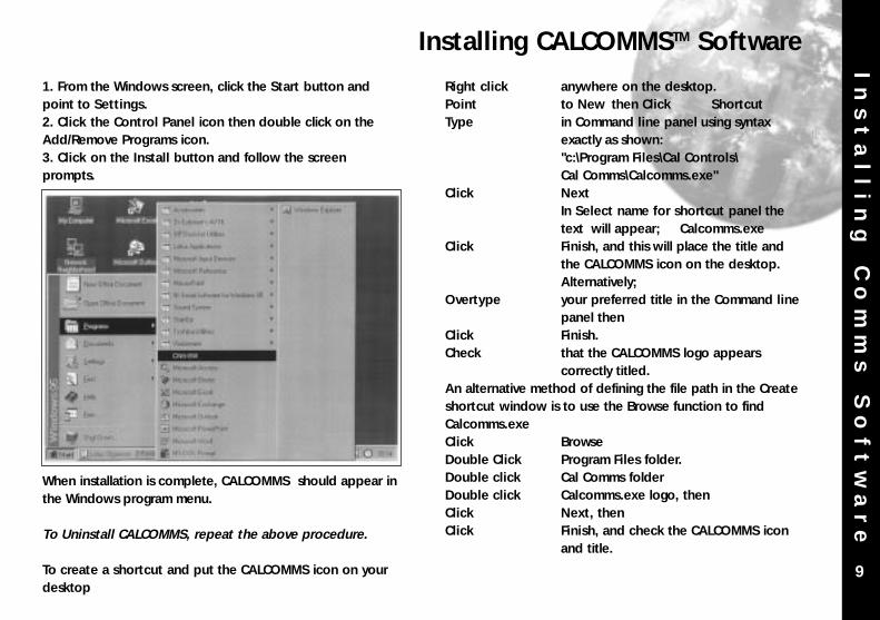
1. From the Windows screen, click the Start button andpoint to Settings.2. Click the Control Panel icon then double click on theAdd/Remove Programs icon.3. Click on the Install button and follow the screenprompts.
When installation is complete, CALCOMMS should appear inthe Windows program menu.
To Uninstall CALCOMMS, repeat the above procedure.
To create a shortcut and put the CALCOMMS icon on yourdesktop
Right click anywhere on the desktop.Point to New then Click ShortcutType in Command line panel using syntax
exactly as shown: "c:\Program Files\Cal Controls\Cal Comms\Calcomms.exe"
Click NextIn Select name for shortcut panel the text will appear; Calcomms.exe
Click Finish, and this will place the title and the CALCOMMS icon on the desktop. Alternatively;
Overtype your preferred title in the Command linepanel then
Click Finish.Check that the CALCOMMS logo appears
correctly titled.An alternative method of defining the file path in the Createshortcut window is to use the Browse function to findCalcomms.exeClick BrowseDouble Click Program Files folder.Double click Cal Comms folderDouble click Calcomms.exe logo, thenClick Next, thenClick Finish, and check the CALCOMMS icon
and title.

In
st
al
li
ng
C
om
ms
S
of
tw
ar
e Installing Comms Software (continued)
10
To delete a shortcut,Click on the desktop icon then press the delete key

Ge
tt
in
g
St
ar
te
dGetting Started
11
Start the program running from either;a. Windows Start menub. Shortcut icon (if created during CALCOMMS installation)This will open the CALCOMMS window. The screen can be sized using standard Windows controls.
Note; As CALCOMMS is a supervisory program it is notdesigned to be minimised!
ADDING INSTRUMENTSClick the appropriate Add New Instrument icon to call up the type and number of instruments that are to be shown on the screen. Each click produces a new instrument which can also be deleted by using the Close button in the instrument title bar immediately above the instrument screen. Mixed instrument types can be displayed on the same screen.
Click the Arrange Instruments in a grid icon and use the screen prompt to arrange them in the preferred layout.
Click the Make Instruments Larger icon or;
Click the Make Instruments Smaller icon to size them as required.
See screen illustrations overleaf.

CALCOMMS Instrument ScreensG
et
ti
ng
S
ta
rt
ed
12
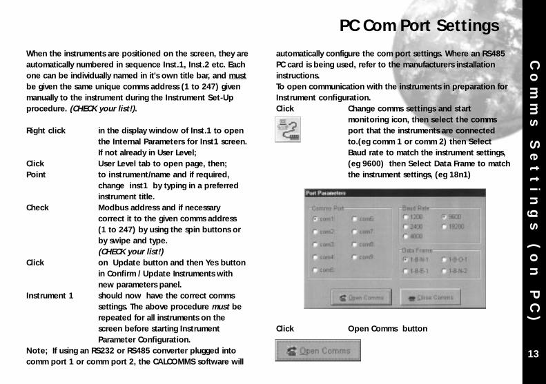
automatically configure the com port settings. Where an RS485PC card is being used, refer to the manufacturers installationinstructions.To open communication with the instruments in preparation forInstrument configuration.Click Change comms settings and start
monitoring icon, then select the comms port that the instruments are connected to.(eg comm 1 or comm 2) then Select Baud rate to match the instrument settings, (eg 9600) then Select Data Frame to matchthe instrument settings, (eg 18n1)
Click Open Comms button
Co
mm
s
Se
tt
in
gs
(
on
P
C)
PC Com Port Settings
13
When the instruments are positioned on the screen, they areautomatically numbered in sequence Inst.1, Inst.2 etc. Eachone can be individually named in it's own title bar, and mustbe given the same unique comms address (1 to 247) givenmanually to the instrument during the Instrument Set-Upprocedure. (CHECK your list!).
Right click in the display window of Inst.1 to open the Internal Parameters for Inst1 screen. If not already in User Level;
Click User Level tab to open page, then;Point to instrument/name and if required,
change inst1 by typing in a preferred instrument title.
Check Modbus address and if necessary correct it to the given comms address(1 to 247) by using the spin buttons or by swipe and type.(CHECK your list!)
Click on Update button and then Yes button in Confirm / Update Instruments with new parameters panel.
Instrument 1 should now have the correct comms settings. The above procedure must be repeated for all instruments on the screen before starting Instrument Parameter Configuration.
Note; If using an RS232 or RS485 converter plugged intocomm port 1 or comm port 2, the CALCOMMS software will

Co
mm
s
Se
tt
in
gs
(
on
P
C)
14
PC Com Port Settings (continued)
Wait!! For update to be fully completed by observing the Uploading bar turning from red to green in the CALCOMMSInstrument screen.This may take several seconds.
Check Virtual instrument display readings against real instrument readings.
If the check is satisfactory, proceed with Instrument Parameter Configuration

Pa
ra
me
te
r
Co
nf
ig
ur
at
io
nInstrument Parameter Configuration
15
The instrument(s) will not be operational until configuredwith the following basic settings.* Sensor type* Units of measurement* Allocation of output devices to the main output SP1 and
second output SP2
To configure the basic settings to Instrument 1
Right Click in the display window of Inst.1 (or new given name) to open the Internal Parameter screen
Click Level 2 tab to open page, thenClick Input sensor box, and select required
sensor from the drop down menu (eg K)Click Process unit box, and select required
unit from the drop down menu (eg oC)Click Level 3 tab to open page, thenClick SP1 output device box, and select
choice of output device from drop down menu (eg rLy)
Note: That SP2 output device box registers thealternative output device (eg SSd) and ifOK, Click the Yes button to confirm selection.
Click User Level tab to open page, and enter a setpoint value in Set Point 1/SP1 Valuebox using spin buttons or swipe and type.
Check The Enable Display Mimics box if you want the virtual instrument to mimic all actual instrument displays as well as reading setpoint and process values.
NB This may slow down communications and should only be used if it serves a useful purpose.
SOFTWARE ALARMS
This feature provides a screen alarm indication if themeasured value falls below the low alarm and/or rises abovethe high alarm settings. The alarm appears as a red band across the lower fascia ofthe instrument.

Pa
ra
me
te
r
Co
nf
ig
ur
at
io
n
16
Instrument Parameter Configuration (continued)
To set Software Alarms (in User Level)Adjust Spin buttons in Low Alarm/ High Alarm
boxes to set the required high/low levelCheck The Enabled boxes.
TO ENTER THE ABOVE INSTRUMENT PARAMETER SETTINGS
Click on Update button and then Yes button in Confirm/Update Instruments with newparameter panel.
Wait For update to be fully completed as indicated by the Uploading bar turning from red to green after it temporarily appears in the CALCOMMS Instrumentscreen.This may take several seconds.After a few seconds more the Heat-On LED in the top left hand corner of the Inst.1 screen will light indicating that thepower is applied to the output. Instrument 1 will control with factory PID settings and pre-set proportional cycle times. For optimum performance the instrument may require Tuning to match the characteristics of the application. For full instruction in setting the controller functions, please consult
the main manual.Autotune routines can be found on page 7.
SETPOINT ADJUSTMENT
During normal use, instrument setpoints can be adjustedfrom the CALCOMMS instrument screen, by using the threebuttons shown on the virtual instrument lower fascia.
button highlighted with red circle in program
Click The button, and while the red circle shows around it, click either the or button to increase or decrease the setpoint value. This setting will be implemented when the red circle disappears after a few seconds.
Note: When more than one instrument is being configured,the outputs of the other instruments can be temporarilyturned off using the ParK option of the TUNE function inlevel 1.

In
st
ru
me
nt
C
lo
ni
ng
Instrument Cloning
17
When a satisfactory instrument configuration has beenachieved, either from the initial configuration with the basicparameter settings, following Autotune or other furtheradjustments, these settings can be cloned to otherinstruments on the network or saved in a file for later use.Suites of settings of all the instruments in an application cansimilarly be saved to a file making it possible to re-configureall of the instruments on a machine or process in a matter ofseconds, to optimise them to different task.
Cloning Settings to another instrument on the bus.
Right Click in the display window of the instrument that settings are to be cloned from.
Click the clone button in any of the pages of the Internal Parameters for instrument (n) screen to call up the Clone datapage. The Instruments on line panel will list all of the instruments on line by it's Modbus address and either the default instrument number or name/location given during Instrument Comms Settingprocedure. To transfer an instrument or group of instruments to the Instruments to Clonepanel;
Click anywhere on instrument title, to highlight, or
Click/hold a group of instrument titles, thenClick the button to transfer the highlighted
instruments to the Instruments to clone panel, then
Click the OK button to clone them with the settings from the original instrument.

Saving/Retrieving Instrument/Application SettingsS
av
in
g
Se
tt
in
gs
t
o
Fi
le
18
Saving the settings of a single instrumentClick Save in the menu bar of the Internal
Parameters for Inst.n screenType Your filename in the File name boxClick the Save boxThis will save the instrument settings to an instrument filewith the extension .ins
Opening an existing instrument fileClick Load in the menu bar of the Internal
Parameters for Inst.n screenClick the Yes button in the Confirm panel to
Load inst.n from file?This will load instrument n settings to the new instrument.
Saving an Application FileIn the CALCOMMS Instruments screenClick File in the menu bar, then Save
Application from the menu. Type Your new filename in the File name box. Click SaveThis will save the settings of all the instruments on thescreen to an application file with the extension .app. Checkthat the file is correctly named Yourtitle.app.
Opening an Existing Application FileClick File in the menu bar, then Open
Application from menuClick File name to select application from the
list then click OpenThis will automatically configure the instruments to thesettings saved in the selected file
Starting a New Application FileClick File in the menu bar and select New
Application from menuClick Yes to confirm Start a new application
Note: When instrument settings are loaded from anapplication file, remember to re-start comms

Se
cu
ri
ty
L
oc
ko
ut
sSecurity Lockouts
19
When the instrument parameters have been established you may wish to password protect the settings against accidental orunauthorised adjustment. It is possible to make individual protection for each instrument function at each level, and for eachinstrument on the network
Please study the lock hierarchy diagram below before implementing your security strategy.When correcting errors, start again from supervisor level, lock none, and clear the locked settings in the correct hierarchicalsequence
SupervisorAll of the controller functions are available to the supervisorwho can deny adjustment of any number of them to lowerlevels in the hierarchy. These settings will be protected bythe supervisor’s password.
OperatorThe operator can adjust all controller functions not lockedby the supervisor, and can in turn lock any of these to denyadjustment to a user, and then protect them with theoperator’s password.
UserAny remaining functions are available for adjustment by theend user. These functions can be locked and unlockedwithout the use of a password.
All Controller Functions
Supervisor
Controller Functions Available to Operator
Operator
Controller Functions Availablefor User Adjustment
Lock Hierarchy
!

parameters you want to lock, or the Allbox or the None box.
Click OK thenClick the tab for the next level, and repeat the
procedure until all levels of Inst.1 have been protected.Repeat for all of the remaininginstruments on the network, then return to CALCOMMS instrument screen.
Click double lock icon in the menu bar to bring up the Password panel, then
Click the arrow in the User type box and select Locked from the drop down menu.
Type your password in the Password box and click OK. The selected levels of the selected instruments are now locked and protected by your password which can be changed at any time using the Change feature.
NB: Once communication has been established and routinefunction adjustments under PC control, it is highlyrecommended that the instrument controls are manuallylocked to prevent unauthorised local adjustment. Whenlocked, it will still be possible to make adjustments fromthe PC.If you forget your password, please contact CAL
Se
cu
ri
ty
L
oc
ko
ut
s
20
Lock Hierarchy
Right click in the display window of Inst.1 to openthe Internal Parameters for
Click the tab for a level that contains any settings that you wish to protect, and
Click the Lock button, and in the Lock User Level Parameter window,
Check either the individual boxes of all the
To implement your security lockout strategy, begin from the CALCOMMS instrument screen, supervisor mode.
Lo
gg
in
g
an
d
Ch
ar
ti
ng
21
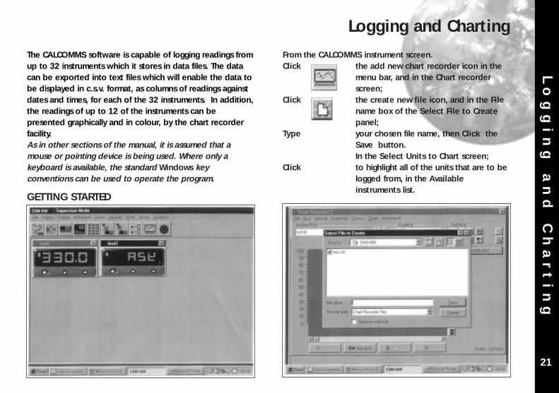
The CALCOMMS software is capable of logging readings fromup to 32 instruments which it stores in data files. The datacan be exported into text files which will enable the data tobe displayed in c.s.v. format, as columns of readings againstdates and times, for each of the 32 instruments. In addition,the readings of up to 12 of the instruments can bepresented graphically and in colour, by the chart recorderfacility.As in other sections of the manual, it is assumed that amouse or pointing device is being used. Where only akeyboard is available, the standard Windows keyconventions can be used to operate the program.
GETTING STARTED
From the CALCOMMS instrument screen.Click the add new chart recorder icon in the
menu bar, and in the Chart recorderscreen;
Click the create new file icon, and in the File name box of the Select File to Createpanel;
Type your chosen file name, then Click the Save button. In the Select Units to Chart screen;
Click to highlight all of the units that are to be logged from, in the Available instruments list.
Logging and Charting

Lo
gg
in
g
an
d
Ch
ar
ti
ng
22
using the Add to Custom Colour feature.Click the OK box in the colour screen.
In the Sample Frequency panel,Click the spin buttons to set the log reading
frequency.Click the OK button to open the Chart
Recorder screen.In the Chart Recorder screen, check that the Active File panel shows the correct file name, then make the following chart recorder settings to suit your application, starting with the Scaling panel;
Logging and Charting (continued)
Click the transfer button to list them in the Instruments to record table. For each instrument to be charted from, double click in the Plot? column to change the No to Yes.
Double click in each instrument colour panel, and from the standard WindowsTM colour chart, select contrasting colours that will effectively display all of the instruments listed. Additional shades can be added

Lo
gg
in
g
an
d
Ch
ar
ti
ng
23
Click the buttons in the deg C/F box to set up a suitable temperature scale in the chart Y axis.
Click the buttons in the time/div box to set
chart speed in the time interval per minordivision of the X axis.
Click the Start button to commence logging and run the chart recorder with default chart settings.
Note: Chart scale settings are determined by the settingschosen for the first instrument (or instrument 1)Traces can be vertically positioned on the chart by usingthe chart scroll buttons.
Click the buttons to move the chart up or down by 10%
Click the buttons to move the chart up or down by 100%
Click the button to zero the chart
The appearance and colours of the chart can be changedas follows;Click select background colour icon, and
chose another colour from the colour chart.
Click the toggle grid intensity icon to add minor divisions to the Y axis.
Click the select primary grid colour icon to change the colour of the grid major divisions.
Click the select grid colour icon to change the colour of the grid minor divisions.
Note: Because the chart is re-drawn after each plot, asetting of less than 5 minutes/div is recommended, to avoidextravagant use of system resources while logging. Longersettings can be used to review the full chart history in viewplot mode.
!

Lo
gg
in
g
an
d
Ch
ar
ti
ng
24
Click the make chart bigger or make chart smaller icons to adjust the size of the chart on your screen.
Click in the chart recorder blue title band, anddrag to adjust the position of the chart recorder on your screen. Repeat this for the CALCOMMS instrument screen, and trim both adjustments so that both
are visible.If you prefer using full screens for both chart and instruments, toggle between screens using the instruments menu bar
option in the chart screen and the chartoption in the instruments screen.
Click the pause button to stop logging and stop the chart recorder.
Click the Resume button to re-start logging and charting.Note that a grey vertical band appears on the right of the chart tosignify the break in readings.
Click the auto plot button to pause the chart and allow the chart history to be viewed using the horizontal scroll bar controls. (normal logging continues meanwhile)
Click the view plot button to return to automatic chart update state and normalcharting is resumed.During charting, the current value is displayed to the right of the chart, in the trace colour. When in view plot mode
Point and Click to any point on the trace. A dashed vertical line will appear and cut the trace at this point, and the value will appear to the right of the chart in place of the current value.If used in auto plot mode the reading willbe set to current value at the next plot.

Lo
g
on
C
ha
ng
e
25
LOG-ON-CHANGE (ONLY LOG/CHART OUT OF LIMITSREADINGS)This feature reduces the size of log and chart files byignoring readings that are within adjustable specified limits.To specify the limits;
Double click in the inst.1 Min column and enter the value below which readings are to be logged. Repeat in the Max column, and enter the value above which readings are to be logged.
Check the radio button record when out of tolerance, and Click the OK button.
The chart will now only register out of limits readings which will be separated by grey vertical bands signifying periods of in limit readings. It will still be necessary to set the Sample Frequencybuttons.
Check the radio button record all readings to return to normal logging/charting.
Factor and Offset adjustmentsA factor adjustment can be made to enable readings ofdiffering orders of magnitude to be charted on the samescale. For example, a X10 factor applied to ambienttemperature readings would enable them to be chartedalongside process temperatures of 200o/400oC -400o/1470oF. Factor adjustments can be greater or less thanone.Offset adjustments can be applied to any trace to adjust itsposition with respect to the scale. For example, the readingsfrom a particular instrument may be known to be 4o lowdue to poor siting of the sensor. An adjustment of +4 in theOffset column will remove this error.
Sizing and positioning your chartClick to make the chart smaller or larger.
If required, it is possible to super-imposea small chart screen on top of or beside the CALCOMMS screen so that both are visible.
Other Logging and Charting Options

Lo
g
on
C
ha
ng
e
26
Saving ChartsTo stop recordingClick Either the close button or from the
menubar chose File then Exit. The file will automatically be saved with the name given earlier as Givenname.cht
Files can be recalled to view, or to add additional data usingthe Append feature.Click the Open existing file icon, and select
the name of the file to be opened from the list in the file box.
Click Open button.
The chart recorder screen will open withthe chart settings returned to default. Ifpreferred, reset the chart to your original settings, then;
Click Append button to add the new readingsto the chart. The new readings will be separated by a vertical grey bar.
Multiple ChartsIt is possible to open a number of charts simultaneously. Themenu will register the number of charts open under thechart heading. These can be arranged on the screen, in orout of view, and moved or sized as required.

Ex
po
rt
in
g
Lo
g
Fi
le
s
27
Exporting Log Files as Text Files
Log files can be exported as "Comma Separated Variable"(csv) text files, which appears as column of loggedinstrument readings, set against its time, date and linenumber.In this form the data can be exported into otherapplications such as spreadsheets or data bases for use inthe preparation of reports or other managementdocuments.
To export data to a text file, in the Chart Recorder screen,
Click the export file in text format icon, and in the Export Text File screen, type your file name in the File name box.
Click the Save button to save your file as a Filename.txt file
To check that your file has been correctly saved, openWindows Explorer
And from the C:\ directory click Program Files then CALControls then CAL Comms
From the list contained under the filepath
C:\Program Files\CALControls\CAL Comms\
Double click Select Filename.txt
Depending on the size of the file, it will be opened in eitherNotepad or WordPad
Printing ChartsCharts can be printed in full colour, depending on thespecification of the printer.From the Chart recorder screen use either the print icon orthe print chart command from Options in the menu bar. Thiswill open the WindowsTM print screen. Click the propertiesbutton to select landscape setting. If changes in appearanceare required, review the logging and charting section.

Tr
ou
bl
e
Sh
oo
ti
ng
28
Trouble Shooting
Error Message Fault Suggested remedy
ASK Comms error Check that the comms address setting of the real and the virtualinstruments are the same.
_ _ _ _ Comms inactive Make sure that comms isopen. Click Change comms
settings and startmonitoring icon.

Gl
os
sa
ry
o
f
Te
rm
s
29
Glossary of Terms
The following definitions apply to terms as they are use inthis manual, and have been worded for ease ofunderstanding. They may differ in detail to definitionsfound elsewhere.
Address The unique number given to each instrument on the network that enables the PC to transmit individual instructions, and receive individual data from it.
Application In this manual it defines the application ofan instrument or group of instruments to control temperatures or other variables on a machine or process.
Application file The stored settings of all of the instruments on a machine or process.
Baud Serial communication consists of a streamof on/off signals called bits. Baud rate is ameasure of the speed of communicationsin bits/second.
Bus The electrical connection linking togetherthe instruments and the PC.
Charting Placing logged readings on a graph format to form a continuous trace of readings where the vertical or Y axis measures the magnitude of the reading and the horizontal or X axis measures elapsed time.
Cloning Copying settings or groups of settings from one instrument to another.
Comms Abbreviation of serial communications.Daisy chain The method of connecting instruments
together.Data format Defines the structure of the message.Functions The main features available in the
controller.Icon Small picture on a PC screen that
describes a CALCOMMS function that can be clicked on to open or close the function.
Level The instruments' functions are grouped on five levels of adjustments for ease of use and protection.
Logging Datalogging; Recording readings against time and or date, into a file.
Modbus Generic name given to the format (protocol) that defines the structure of the coherent groups of signals in serial communications.
Multi drop When several instruments are connectedtogether on a network using RS 485 standard.
Options The choice of settings for the Functions.Password protect The arrangement that enables the user
to lock the system settings against unauthorised adjustment with the use ofa word or code.
Continued over the page

Gl
os
sa
ry
o
f
Te
rm
s
30
Glossary of Terms
Glossary of Terms (continued)
P.C. Personal computer, desktop or laptop.Protocol See Modbus.Radio button A PC "screen" switch shaped like a push
button that can be clicked on and off
RS232/RS485 Sometimes EIA232/EIA485 defines the two standards for serial communication. More detail can be found under Installation/Cabling.
Serial Link Another name for the wiring between two communicating devices.
Virtual Instrument Image of the instrument on the PC screen.

OVERVIEWKey to Program Icons
Ov
er
vi
ew
CALCOMMSTM is a graphic WINDOWSTM based softwarepackage designed for PC supervision of CAL Model 3300and Model 9300 controllers. It offers the capability ofremote adjustment, instrument configuration, cloning, savingand retrieving instrument settings to files together withlogging and charting in real time.
Communication uses the MODBUS® protocol via either afully isolated RS232 or RS485 link depending on the numberof instruments and the transmission distances involved in theapplication.
PC Requirements
To gain the full benefit of CALCOMMS software, it isrecommend that the PC is fitted with a Pentium processorand is running WINDOWS 95 or Windows NT programs. Aminimum of 16 Mb RAM is recommended to run theprogram, together with enough free hard disc space tomeet logging requirements.
This manual assumes that a mouse or other pointing devicewill be employed, but alternatively or in an emergency thestandard WINDOWS key convention can be used to operateor close the program.
Because the controllers are “stand alone” they do not needPC supervision for their normal function, and will continue tocontrol the process unaffected by failure of any part of thecommunications loop.
Ke
y
to
P
ro
gr
am
I
co
ns
Change comms settings &start monitoring
Toggle Modbus commsde-bug window
Add new instrument 3300
Add new instrument 9300
Arrange instruments in grid
Make instruments larger
Make instruments smaller
Set security locks
Add new chart recorder
Close program
Create new file Print chart recorder
Scroll chart up 100%
Scroll chart up 10%
Find chart zero
Scroll chart down 10%
Scroll chart down 100%
Expand verticle scaling range
Decrease verticle scaling range
Increase time/division
Decrease time/division
Open existing file
Export file in text format
Select units to record
Toggle grid density
Select background colour
Select primary grid colour
Select grid colour
Make chart bigger
Make chart smaller
Copyright CAL Controls Ltd. 1997
Not to be reproduced without prior written permission fromCAL Controls Ltd. Whilst every effort has been made to ensurethe accuracy of the specifications contained in this manual,due to our policy of continuous development, CAL Control Ltd.reserves the right to make changes without prior notice.

CALCOMMSTM Manual
CAL ControlsTemperature Controllers
CAL ControlsTemperature Controllers
CAL 3300 and 9300Autotune Temperature
Controllers
CAL Controls LtdBury Mead Road, Hitchin, Herts, SG5 1RT. UK
Tel: + 44 (0)1462-436161 Fax: + 44 (0)1462-451801email: [email protected]
http://www.cal-controls.com
CAL Controls Inc1580 S.Milwaukee Avenue, Libertyville, IL 60048. USA
Tel: (847) 680-7080 Fax: (847) 816-6852
33011/1/1297
INDEX
KEY TO PROGRAM ICONSOVERVIEW (inside front cover)INSTALLATION/CABLING
RS232 1RS485 2Termination resistors 3Bias resistors 4RS232/RS485 features 5
INSTRUMENT COMMS SETTINGS 6CONFIGURING INSTRUMENT COMMS SETTINGS 7-8INSTALLING CALCOMMSTM SOFTWARE 9-10GETTING STARTED 11CALCOMMSTM INSTRUMENT SCREENS 12PC COM PORT SETTINGS 13-14INSTRUMENT PARAMETER CONFIGURATIONSOFTWARE ALARMS 15SETPOINT ADJUSTMENT 16INSTRUMENT CLONING 17SAVING SETTINGS TO FILE 18SECURITY LOCKOUTS 19-20LOGGING AND CHARTING 21-24LOG ON CHANGE 25-26EXPORTING LOG FILES 27TROUBLE SHOOTING 28GLOSSARY OF TERMS 29-30NOTES 31-32
In
de
x