tm010-o&m-001-03 abs class i...
TRANSCRIPT

© BIOQUELL UK LTD52 Royce CloseWest Portway, AndoverHampshire SP10 3TSUnited Kingdom
TM010-O&M-001Revision 3
Tele +44 (0) 1264 835835Fax +44 (0) 1264 835836Email [email protected] www.bioquell.comPage 1 of 61
ADVANCED BIO SAFETY CABINET(ABS)
CLASS I
USER MANUAL
© BIOQUELL UK LTD52 Royce CloseWest Portway, AndoverHampshire SP10 3TSUnited Kingdom
TM010-O&M-001Revision 3
Tele +44 (0) 1264 835835Fax +44 (0) 1264 835836Email [email protected] www.bioquell.comPage 3 of 61
CONTENTS
1 FOREWARD....................................................................................................................................51.1 Safety EnvIronmental Conditions .............................................................................................5
2 INTRODUCTION AND PRINCIPLE OF OPERATION ....................................................................62.1 Responsibility of the User .........................................................................................................7
3 SPECIFICATION .............................................................................................................................73.1 Operating Environment.............................................................................................................73.2 Construction..............................................................................................................................73.3 Dimensions/Weight...................................................................................................................73.4 Electrical ...................................................................................................................................73.5 Working Area ............................................................................................................................83.6 Non Return Valves (Ducted).....................................................................................................83.7 Alarms.......................................................................................................................................83.8 Lighting .....................................................................................................................................93.9 Filtration ....................................................................................................................................93.10 Configurations .......................................................................................................................9
4 INSTALLATION .............................................................................................................................104.1 Position of the cabinet ............................................................................................................104.2 Position of the Fan for Ducted Cabinets.................................................................................104.3 Preparation For Use ...............................................................................................................11
5 OPERATION..................................................................................................................................135.1 Control Panel ..........................................................................................................................13
5.1.1 Mains Power Indicator.....................................................................................................135.1.2 Alarm indicator.................................................................................................................135.1.3 Fan Control......................................................................................................................135.1.4 Fan Off Delay ..................................................................................................................135.1.5 Fan 100% ........................................................................................................................145.1.6 Alarm Mute ......................................................................................................................145.1.7 Test..................................................................................................................................145.1.8 Fluorescent Lights ...........................................................................................................145.1.9 UV Lamp..........................................................................................................................145.1.10 Vaporisation Cycle ..........................................................................................................155.1.11 Gas Supply ......................................................................................................................155.1.12 Keylock and PIN Number Change ..................................................................................15
5.2 Sliding window And Fan Operation ........................................................................................155.2.1 Integral Bypass Operation...............................................................................................17
5.3 Work Surface ..........................................................................................................................185.4 Cabinet Mains Power Connection ..........................................................................................185.5 Safety Control Features..........................................................................................................19
5.5.1 Automatic Air Velocity Control.........................................................................................195.5.2 Automatic Fan Start After Power Failure.........................................................................195.5.3 Hour Meter and Service Date Due ..................................................................................19
6 OPTIONAL EXTRAS .....................................................................................................................206.1 Solenoid Operated Gas Inlet ..................................................................................................206.2 Mains Socket ..........................................................................................................................206.3 Services Tap...........................................................................................................................206.4 Hydrogen Peroxide Connections............................................................................................206.5 Formalin Vaporiser .................................................................................................................206.6 Fireboy Gas Burner ................................................................................................................216.7 Touch-o-matic Gas Burner .....................................................................................................216.8 Stand ......................................................................................................................................216.9 Volt Free Contact....................................................................................................................216.10 Internal Socket Residual Current Device............................................................................226.11 U.V. Light ............................................................................................................................22
6.11.1 High Level U.V. Light.......................................................................................................236.11.2 Portable U.V. Light ..........................................................................................................236.11.3 Remote Start / Stop Switch .............................................................................................23
© BIOQUELL UK LTD52 Royce CloseWest Portway, AndoverHampshire SP10 3TSUnited Kingdom
TM010-O&M-001Revision 3
Tele +44 (0) 1264 835835Fax +44 (0) 1264 835836Email [email protected] www.bioquell.comPage 4 of 61
7 DECONTAMINATION OF THE CABINET.....................................................................................247.1 Sealing of Re-Circulatory Cabinets Prior to Decontamination ...............................................247.2 Decontamination with Hydrogen Peroxide .............................................................................257.3 Decontamination with Formalin ..............................................................................................28
7.3.1 Fumigation with an Integral or Separate Fumigation Unit ...............................................287.3.2 Automatic Fumigation (Option K) ....................................................................................31
7.3.2.1 Running an Automatic Cycle....................................................................................317.3.2.2 Carbon Filter Changing ............................................................................................33
7.4 Gassing the Laboratory ..........................................................................................................338 MAINTENANCE.............................................................................................................................35
8.1 Daily/Frequently......................................................................................................................358.2 Weekly/Monthly ......................................................................................................................358.3 Annual Maintenance, Testing and Re-Calibrations ................................................................358.4 Filter Servicing ........................................................................................................................36
8.4.1 Exhaust filter(s)................................................................................................................368.5 Fluorescent Tube Replacement .............................................................................................368.6 UV Tube Replacement ...........................................................................................................378.7 Circuit Protection ....................................................................................................................37
9 CARE AND CLEANING.................................................................................................................389.1 Bio Organism Removal Cleaning ...........................................................................................389.2 Stainless Steel Components ..................................................................................................389.3 Plastic Components................................................................................................................389.4 Painted and Other Components .............................................................................................39
10 CONTROL SYSTEM: CUSTOMISATION AND CALIBRATION................................................4010.1 Introduction .........................................................................................................................4010.2 Computer and Cable requirements.....................................................................................4010.3 Installing The Set-up Program ............................................................................................4110.4 Customisation of Controls...................................................................................................4210.5 Menu Bar.............................................................................................................................45
10.5.1 File ...................................................................................................................................4510.5.1.1 Load .........................................................................................................................4610.5.1.2 Save .........................................................................................................................4610.5.1.3 Exit ...........................................................................................................................46
10.5.2 PIN Nos. ..........................................................................................................................4610.5.2.1 Read.........................................................................................................................4610.5.2.2 Reset ........................................................................................................................47
10.5.3 Comm Port ......................................................................................................................4710.5.4 Options ............................................................................................................................47
10.5.4.1 Direct Control ...........................................................................................................4710.5.4.2 Show Sensors ..........................................................................................................47
10.6 Miscellaneous functions......................................................................................................4810.6.1 (Dis)Connect....................................................................................................................4810.6.2 Read ................................................................................................................................4810.6.3 Calibrate ..........................................................................................................................4810.6.4 Clear all ...........................................................................................................................4810.6.5 Write ................................................................................................................................48
11 CALIBRATION OF AIRFLOW AND ALARMS ...........................................................................4911.1 Introduction .........................................................................................................................4911.2 Equipment Required ...........................................................................................................4911.3 Airflow Requirements..........................................................................................................4911.4 Calibration Procedure .........................................................................................................49
11.4.1 Initial Set-up and measurement of inflow ........................................................................5011.4.2 Low Inflow........................................................................................................................50
12 TROUBLE SHOOTING ..............................................................................................................5413 SPARES.....................................................................................................................................5514 SERVICING RECORD...............................................................................................................5615 EC DECLARATION OF CONFORMITY ....................................................................................5716 APPROVED SERVICE COMPANY ...........................................................................................5817 SAFETY SYMBOLS...................................................................................................................5918 WARRANTY...............................................................................................................................60

© BIOQUELL UK LTD52 Royce CloseWest Portway, AndoverHampshire SP10 3TSUnited Kingdom
TM010-O&M-001Revision 3
Tele +44 (0) 1264 835835Fax +44 (0) 1264 835836Email [email protected] www.bioquell.comPage 5 of 61
1 FOREWARD
This manual has been specially prepared to give guidance in the use andmaintenance of the:
MMIICCRROOFFLLOOWWCCLLAASSSS II
AADDVVAANNCCEEDD BBIIOO SSAAFFEETTYY CCAABBIINNEETT ((AABBSS)) MMkk IIII
WWAARRNNIINNGGSS::((11)) UUSSEE OOFF TTHHEE CCAABBIINNEETT IINN AA WWAAYY OOTTHHEERR TTHHAANN DDEESSCCRRIIBBEEDD IINN TTHHIISS
MMAANNUUAALL CCOOUULLDD PPRROOVVEE TTOO BBEE VVEERRYY DDAANNGGEERROOUUSS..
((22)) GGEERRMMIICCIIDDAALL LLAAMMPP.. EEMMIITTSS UUVV RRAADDIIAATTIIOONN 225533..77 nnmm.. EEXXPPOOSSUURREEWWIILLLL CCAAUUSSEE DDAAMMAAGGEE TTOO SSKKIINN AANNDD EEYYEESS.. VVAACCAATTEE AARREEAA WWHHEENN IINNUUSSEE..
A list of Safety Symbols used on the Cabinet labels is provided in Section 17.
In order to utilise the full operator protection factors given by the cabinet, itis essential that the operator is fully familiar with the cabinet and all of itsfunctions and controls. This manual should be thoroughly studied beforethe cabinet is used.
This manual contains the operational and first line maintenance instructions.Service and maintenance operations other than those covered by this manualshould only be undertaken by BIOQUELL’s recommended service agent, seeSection 16.
Care should be taken to follow the instructions in this manual to ensure safeoperation. However, if further clarification is required contact your supplier.
1.1 SAFETY ENVIRONMENTAL CONDITIONS
The cabinet is for indoor use only.
The unit is safe to run electrically between 5C and 40C at 10 to 80%humidity, however the unit ought not to be operated outside a temperaturerange of 10 to 35C for it to give the designed operator protection.
Installation category (overvoltage category) II (BS 7671).
Microflow is a registered trademark of BIOQUELL plc.
Windows™ is a trademark of Microsoft Corporation
© BIOQUELL UK LTD52 Royce CloseWest Portway, AndoverHampshire SP10 3TSUnited Kingdom
TM010-O&M-001Revision 3
Tele +44 (0) 1264 835835Fax +44 (0) 1264 835836Email [email protected] www.bioquell.comPage 6 of 61
2 INTRODUCTION AND PRINCIPLE OF OPERATION
The Microflow Cabinet is the result of many years of experience in thedevelopment and use of Safety Cabinets and should give long and trouble-free service provided these simple instructions are followed.
The Microflow ABS Class I Cabinet (Mk II) has been designed to EN12469:2000, which provides operator protection for handling organismsThis is achieved by constantly taking air from the room into the cabinet andthen exhausting it out through a HEPA filter.
The mean inflow must be between 0.7 and 1.0 m/s to ensure operatorprotection is maintained. If the airflow should fall outside these limits thecabinet will alarm
The cabinet can be either a ducted version, where all the air is exhausted outof the cabinet up a duct at the end of which the fan is located. The cabinetcan control the fan to maintain the correct airflow rate if supplied byBIOQUELL. The alternative version re-circulates the air back into thelaboratory after passing through two exhaust filters, note this configurationis not covered by EN12469:2000.
This Cabinet is suitable for working with Category 1, 2 and 3 pathogens
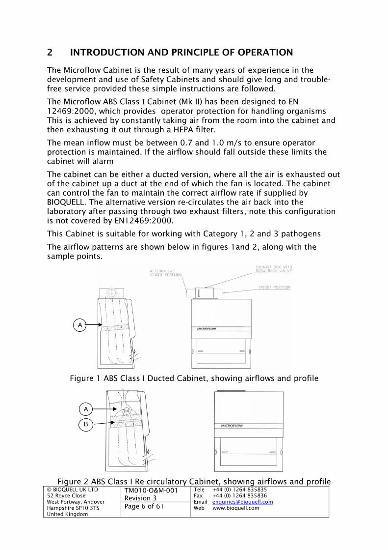
The airflow patterns are shown below in figures 1and 2, along with thesample points.
Figure 1 ABS Class I Ducted Cabinet, showing airflows and profile
Figure 2 ABS Class I Re-circulatory Cabinet, showing airflows and profile
A
A
B
© BIOQUELL UK LTD52 Royce CloseWest Portway, AndoverHampshire SP10 3TSUnited Kingdom
TM010-O&M-001Revision 3
Tele +44 (0) 1264 835835Fax +44 (0) 1264 835836Email [email protected] www.bioquell.comPage 7 of 61
2.1 RESPONSIBILITY OF THE USER
It is not possible to detail all the Safety requirements for every procedureundertaken inside a Safety Cabinet. It is the responsibility of the user toensure safe and proper techniques. Contact BIOQUELL for advice if required.
3 SPECIFICATION
3.1 OPERATING ENVIRONMENT
The cabinet will operate satisfactorily in environments where the ambienttemperature lies between 10 and 35°C. Condensation of moisture on thecabinet must be avoided at all times, as this will affect filter efficiency.
3.2 CONSTRUCTION
The outer shell is of mild steel sheet finished in white powder coating. Thework area is made from 316 stainless steel, with the sides and rear powdercoated.
3.3 DIMENSIONS/WEIGHT
1.0 mCABINET
1.2 mCABINET
1.5 mCABINET
Height (mm) Ducted(including top box)
1580 1580 1580
Height (mm) Re-Circ.(no top box)
1380 1380 1380
Depth (mm) 748 748 748Width (mm) 1190 1390 1690Weight (kg)DuctedRe-circulatory
180190
210220
230240
The maximum load of 25kg which can be placed on the cabinet floor with afoot print of 300mm by 300mm. Large point loads must be avoided.
3.4 ELECTRICAL
Always disconnect the mains supply before removing any cover displayingthe following label:
The ABS cabinet requires:
WARNINGDisconnect the
mains supply beforeremoving this cover
© BIOQUELL UK LTD52 Royce CloseWest Portway, AndoverHampshire SP10 3TSUnited Kingdom
TM010-O&M-001Revision 3
Tele +44 (0) 1264 835835Fax +44 (0) 1264 835836Email [email protected] www.bioquell.comPage 8 of 61
(a) 230 V ±10%, 50 Hz single phase supply.
Power (W) 1.0 mCABINET
1.2 mCABINET
1.5 mCABINET
Ducted* 0.78kW 0.80kW 0.81kWRe-Circulatory 0.78kW 0.80kW 0.81kW
* Includes standard external fan at end of duct run
The internal control system operates at 5 V.
3.5 WORKING AREA
The working area is made of high grade (316L) stainless steel. The tablebelow gives the working area for the different cabinet sizes:
Height(mm)
Width(mm)
Depth(mm)
1.0m Cabinet 635 1000 5301.2m Cabinet 635 1200 5301.5m Cabinet 635 1500 530
The safe working area is shown on the label on the front of the unit, and isall the internal working area.
3.6 NON RETURN VALVES (DUCTED)
A Non Return Valve is located after the HEPA exhaust HEPA filter(s) in the‘top box’ plenum. This is to stop ‘blow-back’ and may not be 100% gas tight,but there will be no leakage of vapour if operated at negative pressure whenbeing de-contaminated. The ‘top box’ may be turned so that the exhaustductwork may be taken either from the right or left hand side.
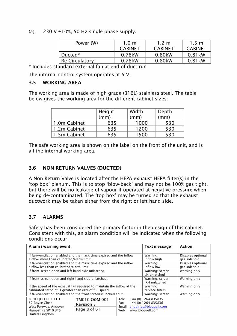
3.7 ALARMS
Safety has been considered the primary factor in the design of this cabinet.Consistent with this, an alarm condition will be indicated when the followingconditions occur:
Alarm / warning event Text message Action
If fan/ventilation enabled and the mask time expired and the inflowairflow more than calibrated/alarm limit.
Warning:Inflow high
Disables optionalgas solenoid.
If fan/ventilation enabled and the mask time expired and the inflowairflow less than calibrated/alarm limit.
Warning:Inflow low
Disables optionalgas solenoid.
If front screen open and left hand side unlatched. Warning: screenLH unlatched
Warning only
If front screen open and right hand side unlatched. Warning: screenRH unlatched
Warning only
If the speed of the exhaust fan required to maintain the inflow at thecalibrated setpoint is greater than 80% of full speed.
Warning:replace filters
Warning only
If fan/ventilation enabled and the front screen is locked shut. Warning: screen Warning only

© BIOQUELL UK LTD52 Royce CloseWest Portway, AndoverHampshire SP10 3TSUnited Kingdom
TM010-O&M-001Revision 3
Tele +44 (0) 1264 835835Fax +44 (0) 1264 835836Email [email protected] www.bioquell.comPage 9 of 61
Alarm / warning event Text message Action
locked shutIf fumigation cycle aborted. Fumigation cycle
ABORTEDWarning only
If fan/ventilation enabled and the mask time expired and exhaustairflow sensor not connected or greater than maximum limit.
Warning: Flowsensor failure
Disables optionalgas solenoid.
If screen right hand side latched in lower position and the left handside unlatched.
Warning: Screenshut LH unlocked
Warning only
If fan/ventilation not enabled and the front screen (window) not shutand latched in the lower position.
Fan off,Window open
Warning only
If service due date exceeded. Service overdue Warning only
If battery backed data not retained after power failure. Note this woulddenote a loss of all calibration setpoints.
Fan 100%Battery Fail
Fan runs at fullspeed
All alarm/warning events will be displayed on the LCD as a text message.The red alarm indicator will flash and unless muted by pressing the Mute button the buzzer will emit a two-tonesound.
3.8 LIGHTING
Fluorescent tubes provide a lighting level in excess of 750 Lux over theworking area.
3.9 FILTRATION
High efficiency filtration is provided by narrow pleated HEPA filters meetingthe requirements of class H14 or higher of EN 1822-1.
3.10 CONFIGURATIONS
Description ‘Top Box’Plenum
IntegralExhaustFan
DoubleExhaustHEPAFilter
FlapValve
RemoteExhaustFanRequired
Ducted X X X
Re-Circulation X X
Integral Bypass X X X
Integral Bypass – Cabinet as Ducted version but with room air intake whencabinet not operating, the room air can be either HEPA filteredor straight from the room
© BIOQUELL UK LTD52 Royce CloseWest Portway, AndoverHampshire SP10 3TSUnited Kingdom
TM010-O&M-001Revision 3
Tele +44 (0) 1264 835835Fax +44 (0) 1264 835836Email [email protected] www.bioquell.comPage 10 of 61
4 INSTALLATION
WWAARRNNIINNGG::IINNSSTTAALLLLAATTIIOONN SSHHOOUULLDD OONNLLYY BBEE CCAARRRRIIEEDD OOUUTT BBYY TTRRAAIINNEEDD AANNDDAAPPPPRROOVVEEDD EENNGGIINNEEEERRSS OORR AAGGEENNTTSS..
BBIIOOQQUUEELLLL OORR IITTSS AAGGEENNTTSS CCAANNNNOOTT AACCCCEEPPTT RREESSPPOONNSSIIBBIILLIITTYY FFOORRDDAAMMAAGGEE,, LLOOSSSS OORR IINNJJUURRYY CCAAUUSSEEDD BBYY,, OORR RREESSUULLTTIINNGG FFRROOMM,,IINNCCOORRRREECCTTLLYY IINNSSTTAALLLLEEDD EEQQUUIIPPMMEENNTT..
WWAARRNNIINNGG::DDOO NNOOTT UUSSEE TTHHEE PPEERROOXXIIDDEE BBLLOOCCKK OORR PPIIPPEESS FFOORR LLIIFFTTIINNGG..
4.1 POSITION OF THE CABINET
The correct functioning of a Safety Cabinet can only be achieved if theCabinet is properly installed. The position of the Cabinet in the Laboratory isimportant. Advice on the correct location of Cabinets is given in ‘The Codeof Practice for Prevention of Infections in Clinical Laboratories and PostMortem Rooms’ published by HMSO and BS EN 12469:2000 andBS5726:2000. The following points should be observed in selecting theposition for the Cabinet:
(a) Is the room of adequate size? About 25 cubic meters (900cubic feet) is generally considered to be the minimum forducted cabinets unless special provision is made for make-upair.
(b) Is the make-up air adequate?
(c) Will the Cabinet be subject to cross movements of airgenerated either by open windows, the ventilation system,exhausts from re-circulation cabinets, or doors being openedand closed near the Cabinet?
(d) Is there space behind the operator movement of other staffwithout disturbing the air flow patterns?
It is recommended that a smoke test be performed in the laboratory where aCabinet is to be sited to ensure that there are no adverse movements of air.A smoke test should also be conducted after the Cabinet has been installedto check the air movements and room pressure while this Cabinet is running.
4.2 POSITION OF THE FAN FOR DUCTED CABINETS
The Fan should be positioned at the exhaust end of the ductwork whichshould terminate outside, thus ensuring that internal ductwork is kept undernegative pressure. Should it be necessary to install the Fan inside thebuilding then the ductwork from the Fan to the outside of the building must
© BIOQUELL UK LTD52 Royce CloseWest Portway, AndoverHampshire SP10 3TSUnited Kingdom
TM010-O&M-001Revision 3
Tele +44 (0) 1264 835835Fax +44 (0) 1264 835836Email [email protected] www.bioquell.comPage 11 of 61
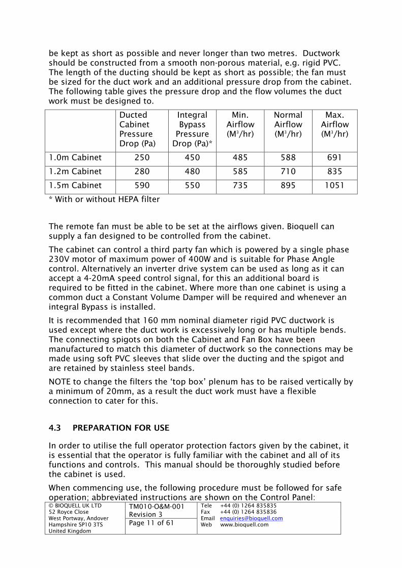
be kept as short as possible and never longer than two metres. Ductworkshould be constructed from a smooth non-porous material, e.g. rigid PVC.The length of the ducting should be kept as short as possible; the fan mustbe sized for the duct work and an additional pressure drop from the cabinet.The following table gives the pressure drop and the flow volumes the ductwork must be designed to.
DuctedCabinetPressureDrop (Pa)
IntegralBypass
PressureDrop (Pa)*
Min.Airflow(M3/hr)
NormalAirflow(M3/hr)
Max.Airflow(M3/hr)
1.0m Cabinet 250 450 485 588 691
1.2m Cabinet 280 480 585 710 835
1.5m Cabinet 590 550 735 895 1051
* With or without HEPA filter
The remote fan must be able to be set at the airflows given. Bioquell cansupply a fan designed to be controlled from the cabinet.
The cabinet can control a third party fan which is powered by a single phase230V motor of maximum power of 400W and is suitable for Phase Anglecontrol. Alternatively an inverter drive system can be used as long as it canaccept a 4-20mA speed control signal, for this an additional board isrequired to be fitted in the cabinet. Where more than one cabinet is using acommon duct a Constant Volume Damper will be required and whenever anintegral Bypass is installed.
It is recommended that 160 mm nominal diameter rigid PVC ductwork isused except where the duct work is excessively long or has multiple bends.The connecting spigots on both the Cabinet and Fan Box have beenmanufactured to match this diameter of ductwork so the connections may bemade using soft PVC sleeves that slide over the ducting and the spigot andare retained by stainless steel bands.
NOTE to change the filters the ‘top box’ plenum has to be raised vertically bya minimum of 20mm, as a result the duct work must have a flexibleconnection to cater for this.
4.3 PREPARATION FOR USE
In order to utilise the full operator protection factors given by the cabinet, itis essential that the operator is fully familiar with the cabinet and all of itsfunctions and controls. This manual should be thoroughly studied beforethe cabinet is used.
When commencing use, the following procedure must be followed for safeoperation; abbreviated instructions are shown on the Control Panel:

© BIOQUELL UK LTD52 Royce CloseWest Portway, AndoverHampshire SP10 3TSUnited Kingdom
TM010-O&M-001Revision 3
Tele +44 (0) 1264 835835Fax +44 (0) 1264 835836Email [email protected] www.bioquell.comPage 12 of 61
(a) Plug in the power lead, if applicable. Switch on power at theswitch located at the power entry point.
(b) Confirm that the blue LED on the control panel is lit,indicating that mains power is applied to the cabinet.
(c) Press and hold down the ‘TEST’ button. All LEDs on thekeypad should light and the buzzer should sound. If not, thecabinet should not be used and maintenance advice sought.
(d) Open the window to operating position (see section 5.2) andpress the ‘FAN’ button, if prompted enter PIN number. The fanwill take about 1 minute to stabilize, during this period thealarms are muted.
(e) It is possible that after the stabilising process, the buzzersounds and the display advises of an airflow alarm. Thepossible causes are as follows:
(i) The first time the cabinet is switched on following amaintenance operation involving use of the set upsoftware.
(ii) The environment of the cabinet is at the extremes of itsoperating temperature (10 - 35°C).
(iii) If the cabinets airflow pattern has been recentlydisturbed.
In any of these cases, the alarm can be expected to clear andafter waiting a few extra seconds.
(f) If an airflow alarm is still displayed after 3 minutes fromswitching on the cabinet, the unit should not be used andadvice sought from your Safety Officer or Supplier.

© BIOQUELL UK LTD52 Royce CloseWest Portway, AndoverHampshire SP10 3TSUnited Kingdom
TM010-O&M-001Revision 3
Tele +44 (0) 1264 835835Fax +44 (0) 1264 835836Email [email protected] www.bioquell.comPage 13 of 61
5 OPERATION
5.1 CONTROL PANEL
The touch controls are located on the Control Panel (Fig. 3) and aredescribed in the following paragraphs.
Figure 3 Control Panel (for illustration purposes only)
5.1.1 Mains Power Indicator
The blue indicator is lit when the mains supply has beenconnected to the cabinet. The indicator remains lit at all times.
5.1.2 Alarm indicator
The alarm indicator flashes whenever an alarm condition occurs.Additionally, unless muted by pressing the MUTE button, thebuzzer emits an alternating two tone signal to give warning of an
alarm condition.
5.1.3 Fan Control
Operation of this switch causes the cabinets internal or externalfan together with the airflow control system to operate. Alarms aremuted for a period of about 1 minute during which time the
display will show the message ‘STABILISING FLOW’. If after this time noalarms are active the correct airflow will have been established and thedisplay will show an appropriate message, for example ‘CABINET SAFE’.
A second press of the fan button causes the fan(s) to be switched off.Alternatively, one of the other fan controls, or the vaporisation cycle can beselected to provide the desired action.
5.1.4 Fan Off Delay
Pressing this button when the fan has been running (LEDs ofbuttons with numbers (1) or (3) lit) will cause the fan to beswitched off after expiry of a timed period.
The delay period is configurable from the set-up software. See Section 10‘Control System: Customisation and Calibration’.
Pressing this button a second time cancels the remaining delay time andswitches off the fan(s).

© BIOQUELL UK LTD52 Royce CloseWest Portway, AndoverHampshire SP10 3TSUnited Kingdom
TM010-O&M-001Revision 3
Tele +44 (0) 1264 835835Fax +44 (0) 1264 835836Email [email protected] www.bioquell.comPage 14 of 61
Once the fan delay is activated, it can alternatively be cancelled by pressingeither of the other two fan functions: buttons (1) or (3). This will initiate therelevant function
5.1.5 Fan 100%
Pressing this button will cause the cabinet’s internal or externalfan to operate at full speed. This facility is intended for emergencyuse after a spillage or other inadvertent activity
A second press of this button will switch the cabinet’s internal or exhaustfan off. Alternatively, either of the other two fan buttons can be pressed inorder to select the desired action.
5.1.6 Alarm Mute
When an alarm condition occurs, the buzzer will sound. Pressingthis button will cause the buzzer to be muted for a configurabletime period of between 0 and 255 minutes. See Section 10
‘Control System: Customisation and Calibration’. The default setting is 4minutes. Cabinets to BS EN 12469 require the default setting at 0 minutes.
The intermittent beeping that accompanies: ‘FLOW STABILISATION’, ‘EXPIREDSERVICE DATE’ messages, or attempts to select incompatible conditions arenot muted.
5.1.7 Test
Correct operation of button indicators and the audible alarm maybe checked by pressing the ‘TEST’ button; all indicators shouldlight and the buzzer should sound with a continuous tone.
The ‘TEST’ function serves the secondary purpose of allowing the ‘HOURSRUN’ and ‘SERVICE DATE DUE’ information to be displayed. This data isuseful in the planning of maintenance operations.
5.1.8 Fluorescent Lights
Pressing this button turns on the cabinet’s fluorescent lighting.With power connected to the cabinet, the lights can be switched onat any time.
If UV lamp is in use or the UV lamp switch has been pressed (UV lamp switchLED lit), it will automatically be switched off when the fluorescent light isselected.
5.1.9 UV Lamp
WWAARRNNIINNGG::DDUUEE TTOO IITTSS HHAAZZAARRDDOOUUSS EEFFFFEECCTTSS,, TTHHEE CCAABBIINNEETT OOPPEERRAATTOORRSSHHOOUULLDD AAVVOOIIDD AANNYY EEXXPPOOSSUURREE TTOO UUVV RRAADDIIAATTIIOONN..
© BIOQUELL UK LTD52 Royce CloseWest Portway, AndoverHampshire SP10 3TSUnited Kingdom
TM010-O&M-001Revision 3
Tele +44 (0) 1264 835835Fax +44 (0) 1264 835836Email [email protected] www.bioquell.comPage 15 of 61
When selected, the UV lamp will remain on for a configurable time periodafter which it will automatically switch off. The default setting is 15 minutes.
The time period for which the UV lamp remains on can be changed, seeSection 10 ‘Control System: Customisation and Calibration’.
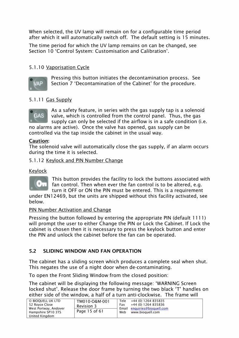
5.1.10 Vaporisation Cycle
Pressing this button initiates the decontamination process. SeeSection 7 ‘Decontamination of the Cabinet’ for the procedure.
5.1.11 Gas Supply
As a safety feature, in series with the gas supply tap is a solenoidvalve, which is controlled from the control panel. Thus, the gassupply can only be selected if the airflow is in a safe condition (i.e.
no alarms are active). Once the valve has opened, gas supply can becontrolled via the tap inside the cabinet in the usual way.
Caution:The solenoid valve will automatically close the gas supply, if an alarm occursduring the time it is selected.
5.1.12 Keylock and PIN Number Change
Keylock
This button provides the facility to lock the buttons associated withfan control. Then when ever the fan control is to be altered, e.g.turn it OFF or ON the PIN must be entered. This is a requirement
under EN12469, but the units are shipped without this facility activated, seebelow.
PIN Number Activation and Change
Pressing the button followed by entering the appropriate PIN (default 1111)will prompt the user to either Change the PIN or Lock the Cabinet. If Lock thecabinet is chosen then it is necessary to press the keylock button and enterthe PIN and unlock the cabinet before the fan can be operated.
5.2 SLIDING WINDOW AND FAN OPERATION
The cabinet has a sliding screen which produces a complete seal when shut.This negates the use of a night door when de-contaminating.
To open the Front Sliding Window from the closed position:
The cabinet will be displaying the following message: ‘WARNING Screenlocked shut’. Release the door frame by turning the two black ‘T’ handles oneither side of the window, a half of a turn anti-clockwise. The frame will
© BIOQUELL UK LTD52 Royce CloseWest Portway, AndoverHampshire SP10 3TSUnited Kingdom
TM010-O&M-001Revision 3
Tele +44 (0) 1264 835835Fax +44 (0) 1264 835836Email [email protected] www.bioquell.comPage 16 of 61
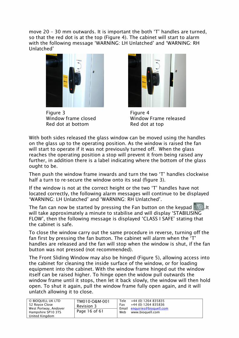
move 20 – 30 mm outwards. It is important the both ‘T’ handles are turned,so that the red dot is at the top (Figure 4). The cabinet will start to alarmwith the following message ‘WARNING: LH Unlatched’ and ‘WARNING: RHUnlatched’
Figure 3 Figure 4Window frame closed Window Frame releasedRed dot at bottom Red dot at top
With both sides released the glass window can be moved using the handleson the glass up to the operating position. As the window is raised the fanwill start to operate if it was not previously turned off. When the glassreaches the operating position a stop will prevent it from being raised anyfurther, in addition there is a label indicating where the bottom of the glassought to be.
Then push the window frame inwards and turn the two ‘T’ handles clockwisehalf a turn to re-secure the window onto its seal (figure 3).
If the window is not at the correct height or the two ‘T’ handles have notlocated correctly, the following alarm messages will continue to be displayed‘WARNING: LH Unlatched’ and ‘WARNING: RH Unlatched’.
The fan can now be started by pressing the Fan button on the keypad .Itwill take approximately a minute to stabilise and will display ‘STABILISINGFLOW’, then the following message is displayed ‘CLASS I SAFE’ stating thatthe cabinet is safe.
To close the window carry out the same procedure in reverse, turning off thefan first by pressing the fan button. The cabinet will alarm when the ‘T’handles are released and the fan will stop when the window is shut, if the fanbutton was not pressed (not recommended).
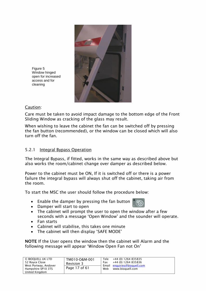
The Front Sliding Window may also be hinged (Figure 5), allowing access intothe cabinet for cleaning the inside surface of the window, or for loadingequipment into the cabinet. With the window frame hinged out the windowitself can be raised higher. To hinge open the widow pull outwards thewindow frame until it stops, then let it back slowly, the window will then holdopen. To shut it again, pull the window frame fully open again, and it willunlatch allowing it to close.
© BIOQUELL UK LTD52 Royce CloseWest Portway, AndoverHampshire SP10 3TSUnited Kingdom
TM010-O&M-001Revision 3
Tele +44 (0) 1264 835835Fax +44 (0) 1264 835836Email [email protected] www.bioquell.comPage 17 of 61
Caution:
Care must be taken to avoid impact damage to the bottom edge of the FrontSliding Window as cracking of the glass may result.
When wishing to leave the cabinet the fan can be switched off by pressingthe fan button (recommended), or the window can be closed which will alsoturn off the fan.
5.2.1 Integral Bypass Operation
The Integral Bypass, if fitted, works in the same way as described above butalso works the room/cabinet change over damper as described below.
Power to the cabinet must be ON, If it is switched off or there is a powerfailure the integral bypass will always shut off the cabinet, taking air fromthe room.
To start the MSC the user should follow the procedure below:
Enable the damper by pressing the fan button Damper will start to open The cabinet will prompt the user to open the window after a few
seconds with a message ‘Open Window’ and the sounder will operate. Fan starts Cabinet will stabilise, this takes one minute The cabinet will then display ‘SAFE MODE’
NOTE If the User opens the window then the cabinet will Alarm and thefollowing message will appear ‘Window Open Fan not On’
Figure 5Window hingedopen for increasedaccess and forcleaning

© BIOQUELL UK LTD52 Royce CloseWest Portway, AndoverHampshire SP10 3TSUnited Kingdom
TM010-O&M-001Revision 3
Tele +44 (0) 1264 835835Fax +44 (0) 1264 835836Email [email protected] www.bioquell.comPage 18 of 61
To switch off the Cabinet and extract air from the room
EITHER (recommended): Fan button can be pressed Cabinet will alarm, prompting the user to shut the window Damper will close off cabinet
OR: The window is shut Damper will close off cabinet
If the fan requires switching off and the window is required to remainopen then this can be achieved without the Cabinet alarming with thefollowing procedure:
Fan Time delay button is pressed Cabinet continues to run for a pre-set time The damper will close off the cabinet
5.3 WORK SURFACE
The actual working surface is lower than its edges so that minor spillageswill be contained.
5.4 CABINET MAINS POWER CONNECTION
Mains power connection to the cabinet is made by the use of a standard IEC3 pin connector assembly incorporating dual pole fusing and an isolatorswitch (Fig. 6).
Figure 6 Mains Connector and Switch

© BIOQUELL UK LTD52 Royce CloseWest Portway, AndoverHampshire SP10 3TSUnited Kingdom
TM010-O&M-001Revision 3
Tele +44 (0) 1264 835835Fax +44 (0) 1264 835836Email [email protected] www.bioquell.comPage 19 of 61
5.5 SAFETY CONTROL FEATURES
5.5.1 Automatic Air Velocity Control
The control system automatically compensates the airflow for the dirtying offilters and variations in the mains power supply. Whenever the airflow iswithin safe operating conditions, the display reports the message ‘CABINETSAFE’.
If an alarm condition is detected, the buzzer will sound and the alarm LEDwill flash; the cause of the alarm will be reported on the display.
After switching on the cabinet from cold, an airflow alarm may occur for ashort period. This is due to the stabilisation of flow sensors and airflows.During stabilisation, the display shows the message ‘STABILISING FLOW’.
5.5.2 Automatic Fan Start After Power Failure
In the event of power disconnection from the cabinet while the fan isoperating, reconnection of the power will cause the fan to start. However, allother functions will be automatically set to off and, if required, they must bereselected. If Fumigating with Formalin the cycle will re-start automaticallyfrom the beginning of the phase it was in when the power disconnectionoccurred
5.5.3 Hour Meter and Service Date Due
These parameters can be viewed on the display by pressing the ‘TEST’button.
© BIOQUELL UK LTD52 Royce CloseWest Portway, AndoverHampshire SP10 3TSUnited Kingdom
TM010-O&M-001Revision 3
Tele +44 (0) 1264 835835Fax +44 (0) 1264 835836Email [email protected] www.bioquell.comPage 20 of 61
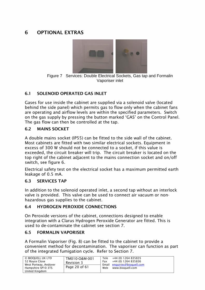
6 OPTIONAL EXTRAS
Figure 7 Services: Double Electrical Sockets, Gas tap and FormalinVaporiser inlet
6.1 SOLENOID OPERATED GAS INLET
Gases for use inside the cabinet are supplied via a solenoid valve (locatedbehind the side panel) which permits gas to flow only when the cabinet fansare operating and airflow levels are within the specified parameters. Switchon the gas supply by pressing the button marked ‘GAS’ on the Control Panel.The gas flow can then be controlled at the tap.
6.2 MAINS SOCKET
A double mains socket (IP55) can be fitted to the side wall of the cabinet.Most cabinets are fitted with two similar electrical sockets. Equipment inexcess of 300 W should not be connected to a socket, if this value isexceeded, the circuit breaker will trip. The circuit breaker is located on thetop right of the cabinet adjacent to the mains connection socket and on/offswitch, see figure 6.
Electrical safety test on the electrical socket has a maximum permitted earthleakage of 0.5 mA.
6.3 SERVICES TAP
In addition to the solenoid operated inlet, a second tap without an interlockvalve is provided. This valve can be used to connect air vacuum or non-hazardous gas supplies to the cabinet.
6.4 HYDROGEN PEROXIDE CONNECTIONS
On Peroxide versions of the cabinet, connections designed to enableintegration with a Clarus Hydrogen Peroxide Generator are fitted. This isused to de-contaminate the cabinet see section 7.
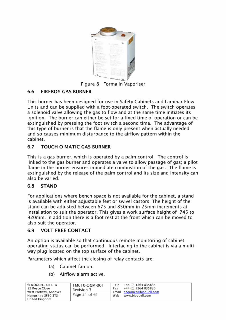
6.5 FORMALIN VAPORISER
A Formalin Vaporiser (Fig. 8) can be fitted to the cabinet to provide aconvenient method for decontamination. The vaporiser can function as partof the integrated fumigation cycle. Refer to Section 7.
© BIOQUELL UK LTD52 Royce CloseWest Portway, AndoverHampshire SP10 3TSUnited Kingdom
TM010-O&M-001Revision 3
Tele +44 (0) 1264 835835Fax +44 (0) 1264 835836Email [email protected] www.bioquell.comPage 21 of 61
Figure 8 Formalin Vaporiser
6.6 FIREBOY GAS BURNER
This burner has been designed for use in Safety Cabinets and Laminar FlowUnits and can be supplied with a foot-operated switch. The switch operatesa solenoid valve allowing the gas to flow and at the same time initiates itsignition. The burner can either be set for a fixed time of operation or can beextinguished by pressing the foot switch a second time. The advantage ofthis type of burner is that the flame is only present when actually neededand so causes minimum disturbance to the airflow pattern within thecabinet.
6.7 TOUCH-O-MATIC GAS BURNER
This is a gas burner, which is operated by a palm control. The control islinked to the gas burner and operates a valve to allow passage of gas; a pilotflame in the burner ensures immediate combustion of the gas. The flame isextinguished by the release of the palm control and its size and intensity canalso be varied.
6.8 STAND
For applications where bench space is not available for the cabinet, a standis available with either adjustable feet or swivel castors. The height of thestand can be adjusted between 675 and 850mm in 25mm increments atinstallation to suit the operator. This gives a work surface height of 745 to920mm. In addition there is a foot rest at the front which can be moved toalso suit the operator.
6.9 VOLT FREE CONTACT
An option is available so that continuous remote monitoring of cabinetoperating status can be performed. Interfacing to the cabinet is via a multi-way plug located on the top surface of the cabinet.
Parameters which affect the closing of relay contacts are:
(a) Cabinet fan on.
(b) Airflow alarm active.
© BIOQUELL UK LTD52 Royce CloseWest Portway, AndoverHampshire SP10 3TSUnited Kingdom
TM010-O&M-001Revision 3
Tele +44 (0) 1264 835835Fax +44 (0) 1264 835836Email [email protected] www.bioquell.comPage 22 of 61
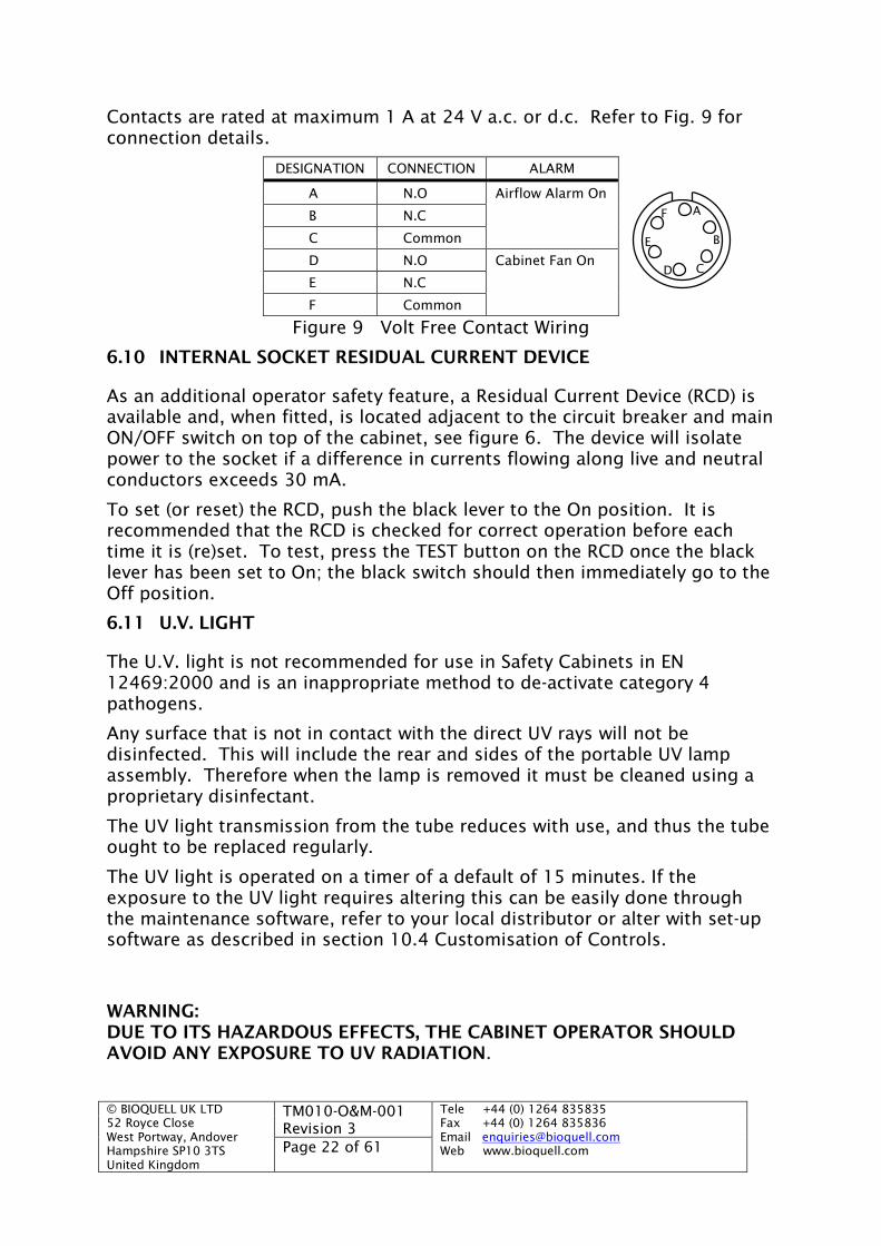
Contacts are rated at maximum 1 A at 24 V a.c. or d.c. Refer to Fig. 9 forconnection details.
DESIGNATION CONNECTION ALARM
A N.O Airflow Alarm On
B N.C
C Common
D N.O Cabinet Fan On
E N.C
F Common
Figure 9 Volt Free Contact Wiring
6.10 INTERNAL SOCKET RESIDUAL CURRENT DEVICE
As an additional operator safety feature, a Residual Current Device (RCD) isavailable and, when fitted, is located adjacent to the circuit breaker and mainON/OFF switch on top of the cabinet, see figure 6. The device will isolatepower to the socket if a difference in currents flowing along live and neutralconductors exceeds 30 mA.
To set (or reset) the RCD, push the black lever to the On position. It isrecommended that the RCD is checked for correct operation before eachtime it is (re)set. To test, press the TEST button on the RCD once the blacklever has been set to On; the black switch should then immediately go to theOff position.
6.11 U.V. LIGHT
The U.V. light is not recommended for use in Safety Cabinets in EN12469:2000 and is an inappropriate method to de-activate category 4pathogens.
Any surface that is not in contact with the direct UV rays will not bedisinfected. This will include the rear and sides of the portable UV lampassembly. Therefore when the lamp is removed it must be cleaned using aproprietary disinfectant.
The UV light transmission from the tube reduces with use, and thus the tubeought to be replaced regularly.
The UV light is operated on a timer of a default of 15 minutes. If theexposure to the UV light requires altering this can be easily done throughthe maintenance software, refer to your local distributor or alter with set-upsoftware as described in section 10.4 Customisation of Controls.
WARNING:DUE TO ITS HAZARDOUS EFFECTS, THE CABINET OPERATOR SHOULDAVOID ANY EXPOSURE TO UV RADIATION.
A
B
CD
F
E

© BIOQUELL UK LTD52 Royce CloseWest Portway, AndoverHampshire SP10 3TSUnited Kingdom
TM010-O&M-001Revision 3
Tele +44 (0) 1264 835835Fax +44 (0) 1264 835836Email [email protected] www.bioquell.comPage 23 of 61
6.11.1 High Level U.V. Light
The high level U.V. light is permanently fitted and is operated by use of theU.V. light switch (see section 5.1.9). As a safety feature the internalfluorescent lighting must be switched off and the window shut, prior toswitching on the U.V. light, otherwise it will not operate.
6.11.2 Portable U.V. Light
Place the Portable U.V. light at the front of the cabinet positioned centrallyalong its length. The power lead can then be connected to the socket(labelled ‘UV’) on the internal wall of the cabinet. Two safety relatedinterlocks are incorporated into the circuit powering the UV lamp:
The front viewing panel must be fully closed, thereby achieving thealignment of a magnet on the window with a reed switch in the rear of thelamp casing. If alignment of the two components is not achieved, the lampwill not function. A series of holes on the rear of the lamp casing indicatethe position of the switch; if the UV light does not work when expected,adjust its position slightly.
The fluorescent lights must be switched off. Unless these lamps are off, itwill not be possible to switch on the UV lamp.
The U.V. light is operated by use of the U.V. light switch (see section 5.1.9).
6.11.3 Remote Start / Stop Switch
A remote start/ stop switch can be supplied to be fitted outside the roomwhere the cabinet is fitted. This key switch requires turning momentarily toinitiate the stopping of the fan and starting it, replicating the fan button.Note that the window on the cabinet must be in operating position otherwisethe cabinet will alarm and not operate.
Note if an Integral Bypass is fitted the Fan time delay button must be used toswitch to the room air, as this allows the window to be left open without thealarm sounding. If turned off at the remote keyswitch the alarm will notsound either.
© BIOQUELL UK LTD52 Royce CloseWest Portway, AndoverHampshire SP10 3TSUnited Kingdom
TM010-O&M-001Revision 3
Tele +44 (0) 1264 835835Fax +44 (0) 1264 835836Email [email protected] www.bioquell.comPage 24 of 61
7 DECONTAMINATION OF THE CABINET
It is recommended that the cabinet be kept clean and free of dust byswabbing down or washing down with a suitable disinfectant. Disposablegloves should be worn for this task. Do not use any Chlorine based cleaningagents.
The cabinet should be kept clean and free of unnecessary equipment.
Decomtamination would be necessary at the following times:
(a) Before carrying out any maintenance work.
(b) Before changing high efficiency filters.
(c) Before performance testing is carried out.
(d) Before moving, relocating or in any way disturbing thecabinet.
(e) Before instituting a change in the work program.
(f) After a gross spillage - as defined by your Safety Officer.
(g) To decontaminate any equipment or materials before theirremoval from the cabinet.
(h) Periodically as required by your Safety Officer.
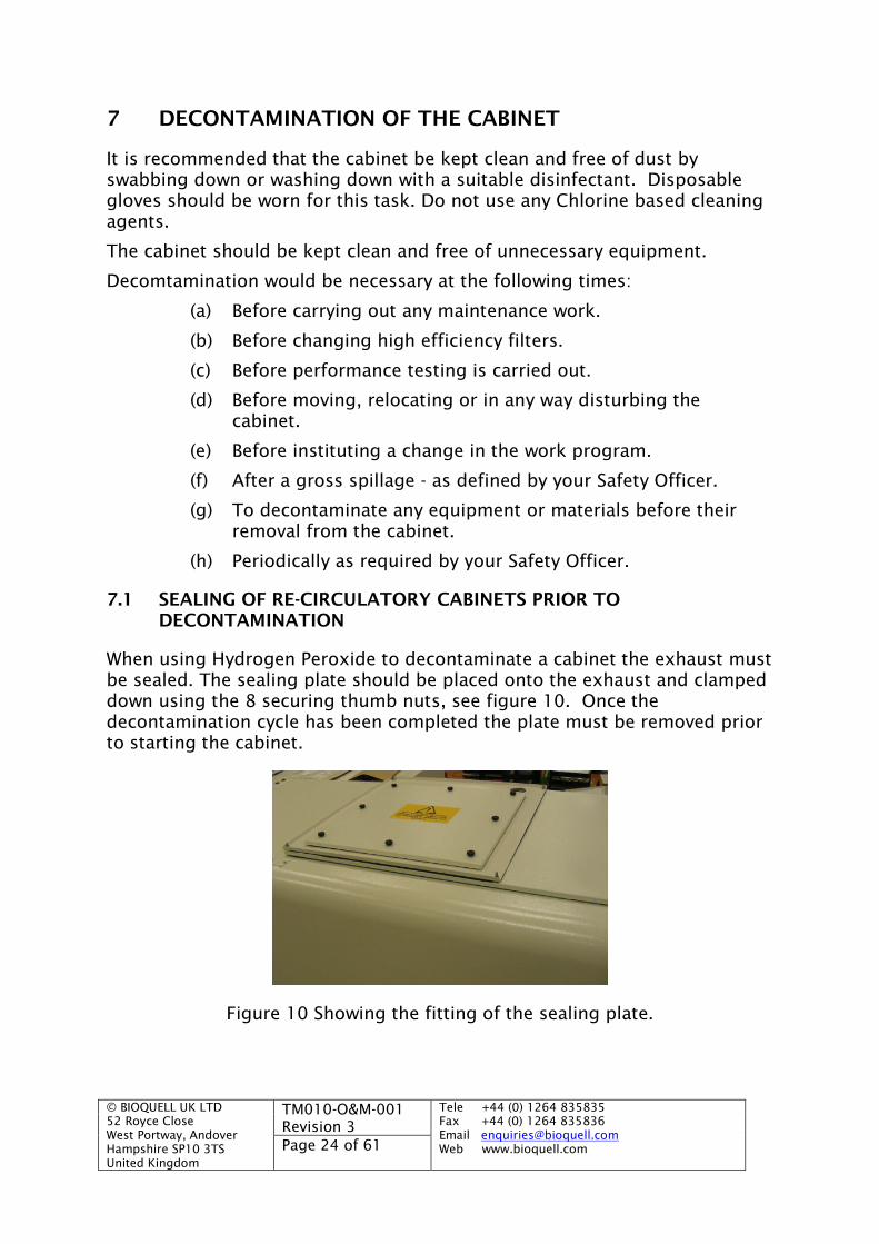
7.1 SEALING OF RE-CIRCULATORY CABINETS PRIOR TODECONTAMINATION
When using Hydrogen Peroxide to decontaminate a cabinet the exhaust mustbe sealed. The sealing plate should be placed onto the exhaust and clampeddown using the 8 securing thumb nuts, see figure 10. Once thedecontamination cycle has been completed the plate must be removed priorto starting the cabinet.
Figure 10 Showing the fitting of the sealing plate.

© BIOQUELL UK LTD52 Royce CloseWest Portway, AndoverHampshire SP10 3TSUnited Kingdom
TM010-O&M-001Revision 3
Tele +44 (0) 1264 835835Fax +44 (0) 1264 835836Email [email protected] www.bioquell.comPage 25 of 61
7.2 DECONTAMINATION WITH HYDROGEN PEROXIDE
This method of bio-decontamination requires a BIOQUELL Clarus HydrogenPeroxide Gas Generator, alternatively the Bioquell EBDS Hydrogen PeroxideBio-decontamination service.
The following instructions relate to the use of a ‘Peroxide’ Cabinet and aClarus L2. A Clarus C can be used, refer to Bioquell for details. If the unit isnot a Peroxide Cabinet the Bioquell EBDS service can still bio-decontaminateit with a simple site modification.
(a) Check that the cabinet is running in SAFE MODE.
(b) Release the window locks and pull the window down, the fans will stopworking, then lock the window shut by use of the two ‘T’ handles oneither side of the window.
(c) If the unit is Ducted ensure that it is safe to vent Hydrogen Peroxidethrough the duct work. If the unit is a re-circulatory cabinet then blankoff the exhaust into the room, or attach a vent pipe to the outside forsafe external ventilation or otherwise the Clarus can Aerate on its own,although this may take a long time.
(d) Connect the hoses, large diameter is supply and blue is return, and thepressure tube to the connectors on the rear of the Clarus L 2.
Connect the other end of the hoses and the pressure tube to thecorresponding connectors on the right-hand side of the Cabinet asshown in Figure 11. The blue hose connects into the top connectionand the large diameter hose in the bottom, with the pressure tubeconnected in the centre. Note for the Clarus L2 these connections arerequired to be 1.5”. The cabinet is, as standard, supplied with 1”connections for decontamination using the BIOQUELL EBDS service.
Figure 11 Cabinet Hose and Pressure Tube Connection
There are two different types of cycles which are available, either a filterdecontamination cycle which ought to be used if the filters are going to bechanged or the filter integrity is to be broken for any other reason. Or there

© BIOQUELL UK LTD52 Royce CloseWest Portway, AndoverHampshire SP10 3TSUnited Kingdom
TM010-O&M-001Revision 3
Tele +44 (0) 1264 835835Fax +44 (0) 1264 835836Email [email protected] www.bioquell.comPage 26 of 61
is a workspace decontamination cycle which can be used to decontaminatethe working area. This is a suitable procedure when general servicing of thecabinet is to be done, or a bio-decontamination is required betweenexperiments to stop cross-contamination. The advantage of the workspaceonly decontamination is that it is significantly shorter.
Running a Filter Decontamination Cycle
a) Run a decontamination cycle with the Clarus according to the Clarusmanual.
The following cycle parameters ought to be set for bio-decontamination of the filters.
Remote Start OFFPressure Test Only OFFTest Pressure, Test Time, Test decay, can be ignoredAeration Only OFFPressure Control ONAeration Pressure Control OFF*Pressure Setpoint -10PaPressure Low Alarm -80PaPressure High Alarm 0PaAirflow setpoint 20 m3/hrDelivery Temperature 60°CConditioning Parametric OFFConditioning Time 10 minutesGassing Time 25 mins for 1.0 &1.2m and 35mins for
1.5 & 1.8mGassing Injection rate 4 g/minH2O2 Alert level 100ppmDwell Time 15 minutesInjection in Dwell NoDwell Injection Rate Can be ignoredTotal Injection Limit 5%Aeration VFC Delay Can be ignoredAeration Parametric OFFAeration time 100 minutesH2O2 Concentration 30%Nozzle Alarm Enable OFF
* If it is not possible to purge using the duct or vent pipe set to ON
When Aeration starts it is highly desirable to exhaust the peroxidethrough the duct work or temporary vent to atmosphere as the timetaken to purge will be dramatically reduced.
CHECK WITH THE HEALTH AND SAFETY OFFICER FIRST. THEREWILL BE HIGH LEVELS OF HYDROGEN PEROXIDE IMMIDIATELYLOCAL TO THE EXHAUST OUTLET
© BIOQUELL UK LTD52 Royce CloseWest Portway, AndoverHampshire SP10 3TSUnited Kingdom
TM010-O&M-001Revision 3
Tele +44 (0) 1264 835835Fax +44 (0) 1264 835836Email [email protected] www.bioquell.comPage 27 of 61
If it is not possible to purge externally the Clarus L2 can carry out theAeration. When it has been deemed safe through independentsampling of the cabinet’s air the Aeration phase on the Clarus L2 canbe completed and the cabinet returned to normal. Check the level ofHydrogen Peroxide in the cabinet by independent means, if below1ppm the cabinet is safe to use.
Running a Workspace Decontamination Cycle
a) Run a decontamination cycle with the Clarus according to the Clarusmanual.
The following cycle parameters ought to be set for bio-decontamination of the workspace.
Remote Start OFFPressure Test Only OFFTest Pressure, Test Time, Test decay, can be ignoredAeration Only OFFPressure Control ONAeration Pressure Control OFF*Pressure Setpoint -10PaPressure Low Alarm -80PaPressure High Alarm 0PaAirflow setpoint 20 m3/hrDelivery Temperature 60°CConditioning Parametric OFFConditioning Time 10 minutesGassing Time 8 minsGassing Injection rate 4 g/minH2O2 Alert level 100ppmDwell Time 10 minutesInjection in Dwell NoDwell Injection Rate Can be ignoredTotal Injection Limit 5%Aeration VFC Delay Can be ignoredAeration Parametric OFFAeration time 60 minutesH2O2 Concentration 30%Nozzle Alarm Enable OFF
* If it is not possible to purge using the duct or vent pipe set to ON
b) With the window locked down start the Clarus L2 cycle.
c) After 28 minutes the Clarus L2 will be starting Aeration, it is highlydesirable to exhaust the peroxide through the duct work or temporaryvent to atmosphere by use of an Option B or C as the time taken topurge will be dramatically reduced.
© BIOQUELL UK LTD52 Royce CloseWest Portway, AndoverHampshire SP10 3TSUnited Kingdom
TM010-O&M-001Revision 3
Tele +44 (0) 1264 835835Fax +44 (0) 1264 835836Email [email protected] www.bioquell.comPage 28 of 61
CHECK WITH THE HEALTH AND SAFETY OFFICER FIRST. THEREWILL BE HIGH LEVELS OF HYDROGEN PEROXIDE IMMIDIATELYLOCAL TO THE EXHAUST OUTLET
To purge up the ductwork or temporary vent:
Open the cabinet’s window to its normal working height slowly and lock inposition. When the window is opened the fan will come on immediately.
WARNING THERE WILL BE HIGH LEVELS OF HYDROGEN PEROXIDE IN THECABINET, CARE MUST BE TAKEN WHILE THE FAN IS STARTING AS SOMEPEROXIDE MAY EXIT THE WORKSPACE. DO NOT FULLY OPEN THEWINDOW OR INHALE AIR FROM THE WORKSPACE UNTIL SAFE LEVELS OFPEROXIDE HAVE BEEN ESTABLISHED.
When the cycle on the Clarus L 2 has completed check the level of HydrogenPeroxide in the cabinet by independent means, if below 1ppm the cabinet issafe to use.
No external Purge
If it is not possible to purge externally the Clarus L2 can carry out theAeration, then the cabinet ought to be left in the same state as for gassing.
At the end of Aeration by the Clarus L2 the operator ought to check the levelof Hydrogen Peroxide in the cabinet by independent means, if below 1ppmthe cabinet is safe to use.
7.3 DECONTAMINATION WITH FORMALIN
Formaldehyde and Formalin are hazardous: observe handling procedures.
Ensure that the cabinet is free of Hydrochloric acid and other Chlorocompounds. This will avoid the production of the carcinogenic product thatresults from the mixing of formaldehyde and HCl or Chloride gas.
The following procedure is provided for guidance purposes only; your SafetyOfficer should be consulted for definitive guidance.
Formaldehyde penetrates poorly and its effectiveness is dependendent ontemperature and humidity. It is most effective above a temperature of 20Cand a relative humidity of 65%. Use of excessive amounts can result inpolymer deposition within the cabinet and may contribute to filter blockage.
7.3.1 Fumigation with an Integral or Separate Fumigation Unit
If a stand alone separate fumigation unit is used, which is then plugged intothe internal socket, the same procedure can be followed as described below,but the vaporiser unit will have to be turned on manually.
© BIOQUELL UK LTD52 Royce CloseWest Portway, AndoverHampshire SP10 3TSUnited Kingdom
TM010-O&M-001Revision 3
Tele +44 (0) 1264 835835Fax +44 (0) 1264 835836Email [email protected] www.bioquell.comPage 29 of 61
A safe manner to exhaust the fumigant is required, the following are a list ofcommon methods:
Use the existing Ducting for permanently ducted cabinets Fit temporary ducting to a central duct or other exhaust system Fit a Formalin Evacuation unit to the exhaust, a small portable
unit designed specifically for this purpose, available fromBIOQUELL.
Use an in-built filter for removing the vapor, only fitted to OptionK versions of the cabinet, refer to section 7.2.2
The cabinet display prompts the user throughout the fumigation cycle.
A safety feature built into the control system is that if the Window isdisturbed during the evaporation or fumigating processes, the fan willautomatically be switched on in order to safely expel the fumigant up theduct work. It is therefore most important the extract duct work is fitted priorto the start of the cycle. In such a situation the fan will continue to run untilthe Keylock button is pressed and the fumigation PIN number has beenentered for a second time.
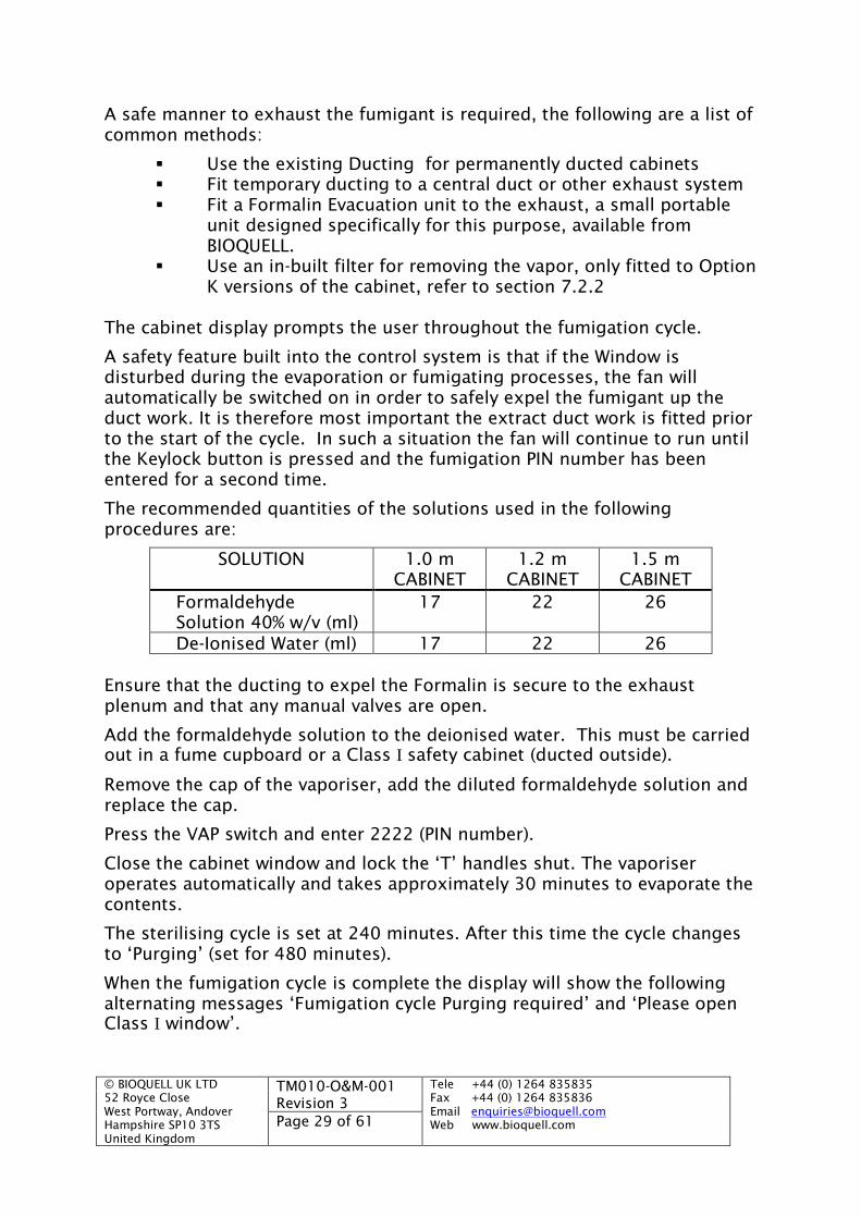
The recommended quantities of the solutions used in the followingprocedures are:
SOLUTION 1.0 mCABINET
1.2 mCABINET
1.5 mCABINET
FormaldehydeSolution 40% w/v (ml)
17 22 26
De-Ionised Water (ml) 17 22 26
Ensure that the ducting to expel the Formalin is secure to the exhaustplenum and that any manual valves are open.
Add the formaldehyde solution to the deionised water. This must be carriedout in a fume cupboard or a Class I safety cabinet (ducted outside).
Remove the cap of the vaporiser, add the diluted formaldehyde solution andreplace the cap.
Press the VAP switch and enter 2222 (PIN number).
Close the cabinet window and lock the ‘T’ handles shut. The vaporiseroperates automatically and takes approximately 30 minutes to evaporate thecontents.
The sterilising cycle is set at 240 minutes. After this time the cycle changesto ‘Purging’ (set for 480 minutes).
When the fumigation cycle is complete the display will show the followingalternating messages ‘Fumigation cycle Purging required’ and ‘Please openClass I window’.

© BIOQUELL UK LTD52 Royce CloseWest Portway, AndoverHampshire SP10 3TSUnited Kingdom
TM010-O&M-001Revision 3
Tele +44 (0) 1264 835835Fax +44 (0) 1264 835836Email [email protected] www.bioquell.comPage 30 of 61
The operator ought to open the window, or if a Formaldehyde Extraction Unitis being used switch it on first for 10 to 15 seconds and allow the unit to runfor the purging time.
Periodically check the room with a formaldehyde meter (this should read lessthan 2 ppm formaldehyde).
Purging will continue until the purge time has expired. The cabinet will thenreturn to normal cabinet functions.
Remove the temporary duct/Evacuation unit (close the orange valve first) asappropriate and run the Cabinet as normal and check the room with aFormaldehyde Meter.
A description of the cycle is provided in Table 1.
© BIOQUELL UK LTD52 Royce CloseWest Portway, AndoverHampshire SP10 3TSUnited Kingdom
TM010-O&M-001Revision 3
Tele +44 (0) 1264 835835Fax +44 (0) 1264 835836Email [email protected] www.bioquell.comPage 31 of 61
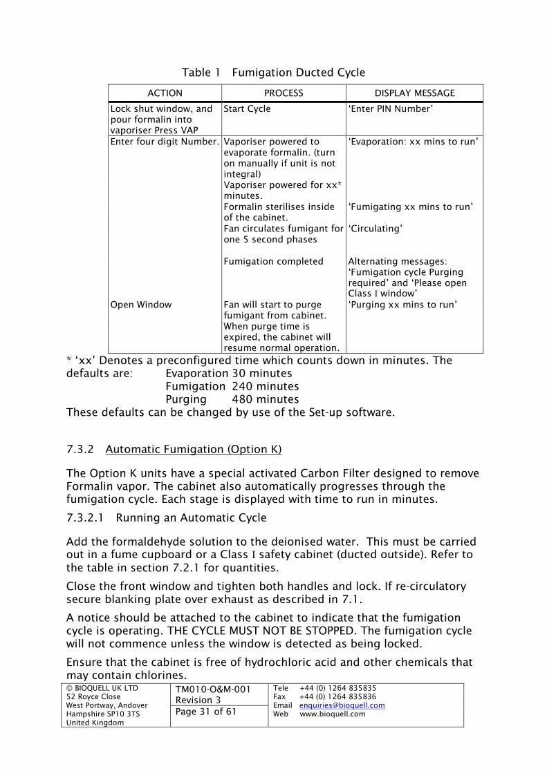
Table 1 Fumigation Ducted Cycle
ACTION PROCESS DISPLAY MESSAGE
Lock shut window, andpour formalin intovaporiser Press VAP
Start Cycle ‘Enter PIN Number’
Enter four digit Number. Vaporiser powered toevaporate formalin. (turnon manually if unit is notintegral)
‘Evaporation: xx mins to run’
Vaporiser powered for xx*minutes.Formalin sterilises insideof the cabinet.
‘Fumigating xx mins to run’
Fan circulates fumigant forone 5 second phases
‘Circulating’
Fumigation completed Alternating messages:‘Fumigation cycle Purgingrequired’ and ‘Please openClass I window’
Open Window Fan will start to purgefumigant from cabinet.
‘Purging xx mins to run’
When purge time isexpired, the cabinet willresume normal operation.
* ‘xx’ Denotes a preconfigured time which counts down in minutes. Thedefaults are: Evaporation 30 minutes
Fumigation 240 minutesPurging 480 minutes
These defaults can be changed by use of the Set-up software.
7.3.2 Automatic Fumigation (Option K)
The Option K units have a special activated Carbon Filter designed to removeFormalin vapor. The cabinet also automatically progresses through thefumigation cycle. Each stage is displayed with time to run in minutes.
7.3.2.1 Running an Automatic Cycle
Add the formaldehyde solution to the deionised water. This must be carriedout in a fume cupboard or a Class I safety cabinet (ducted outside). Refer tothe table in section 7.2.1 for quantities.
Close the front window and tighten both handles and lock. If re-circulatorysecure blanking plate over exhaust as described in 7.1.
A notice should be attached to the cabinet to indicate that the fumigationcycle is operating. THE CYCLE MUST NOT BE STOPPED. The fumigation cyclewill not commence unless the window is detected as being locked.
Ensure that the cabinet is free of hydrochloric acid and other chemicals thatmay contain chlorines.
© BIOQUELL UK LTD52 Royce CloseWest Portway, AndoverHampshire SP10 3TSUnited Kingdom
TM010-O&M-001Revision 3
Tele +44 (0) 1264 835835Fax +44 (0) 1264 835836Email [email protected] www.bioquell.comPage 32 of 61
Remove the cap of the vaporiser, add the diluted formaldehyde solution andreplace the cap.
Press the VAP switch and enter 2222 (PIN number).
The cabinet will then display ‘Fumigation Cycle No X’. X counts from 1 to 10.If run again after the 10th cycle the following message will be displayed,‘Maximum cycles for filter reached’, and the unit will not run any furthercycles until the filter has been changed and the counter reset, see section7.2.2.2.
‘Evaporating X minutes to run’ will be displayed. The vaporiser operatesautomatically and runs for the set time ‘X’ to evaporate the contents. Awarning is displayed not to open the window.
The unit will then progress into fumigating with displaying the time to runand repeating the warning not to open the window.
Finally the purging stage starts with a repeat not to open the window on thedisplay. This is where the vapor will be automatically circulated through thefilter where the formalin vapor is scrubbed out.
When the cabinet has finished the cycle it displays the following message‘Fumigation cycle No X complete’, where ‘X’ is the number of cycles run witha particular filter. The fumigation cycle should be stopped by using the VAPswitch and entering the PIN, and then the blanking plate ought to beremoved and replaced with the spigot. Only then the window ought to beunlocked and the cabinet set to normal operation.
To abort the cycle at any point press the VAP key then enter the PIN andpress the Fan button to start the cabinet.
A description of the cycle is provided in Table 2.
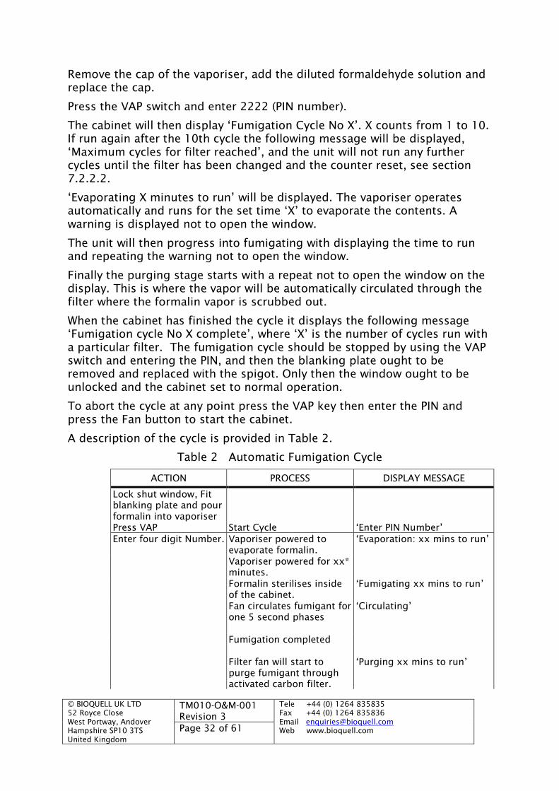
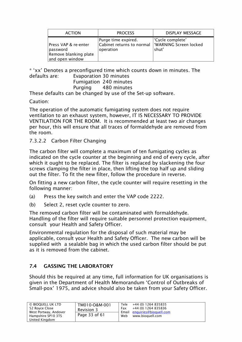
Table 2 Automatic Fumigation Cycle
ACTION PROCESS DISPLAY MESSAGE
Lock shut window, Fitblanking plate and pourformalin into vaporiserPress VAP Start Cycle ‘Enter PIN Number’Enter four digit Number. Vaporiser powered to
evaporate formalin.‘Evaporation: xx mins to run’
Vaporiser powered for xx*minutes.Formalin sterilises insideof the cabinet.
‘Fumigating xx mins to run’
Fan circulates fumigant forone 5 second phases
‘Circulating’
Fumigation completed
Filter fan will start topurge fumigant throughactivated carbon filter.
‘Purging xx mins to run’
© BIOQUELL UK LTD52 Royce CloseWest Portway, AndoverHampshire SP10 3TSUnited Kingdom
TM010-O&M-001Revision 3
Tele +44 (0) 1264 835835Fax +44 (0) 1264 835836Email [email protected] www.bioquell.comPage 33 of 61
ACTION PROCESS DISPLAY MESSAGE
Purge time expired. ‘Cycle complete’Press VAP & re-enterpassword
Cabinet returns to normaloperation
‘WARNING Screen lockedshut’
Remove blanking plateand open window
* ‘xx’ Denotes a preconfigured time which counts down in minutes. Thedefaults are: Evaporation 30 minutes
Fumigation 240 minutesPurging 480 minutes
These defaults can be changed by use of the Set-up software.
Caution:
The operation of the automatic fumigating system does not requireventilation to an exhaust system, however, IT IS NECESSARY TO PROVIDEVENTILATION FOR THE ROOM. It is recommended at least two air changesper hour, this will ensure that all traces of formaldehyde are removed fromthe room.
7.3.2.2 Carbon Filter Changing
The carbon filter will complete a maximum of ten fumigating cycles asindicated on the cycle counter at the beginning and end of every cycle, afterwhich it ought to be replaced. The filter is replaced by slackening the fourscrews clamping the filter in place, then lifting the top half up and slidingout the filter. To fit the new filter, follow the procedure in reverse.
On fitting a new carbon filter, the cycle counter will require resetting in thefollowing manner:
(a) Press the key switch and enter the VAP code 2222.
(b) Select 2, reset cycle counter to zero.
The removed carbon filter will be contaminated with formaldehyde.Handling of the filter will require suitable personnel protection equipment,consult your Health and Safety Officer.
Environmental regulation for the disposal of such material may beapplicable, consult your Health and Safety Officer. The new carbon will besupplied with a sealable bag in which the used carbon filter should be putas it is removed from the cabinet.
7.4 GASSING THE LABORATORY
Should this be required at any time, full information for UK organisations isgiven in the Department of Health Memorandum ‘Control of Outbreaks ofSmall-pox’ 1975, and advice should also be taken from your Safety Officer.
© BIOQUELL UK LTD52 Royce CloseWest Portway, AndoverHampshire SP10 3TSUnited Kingdom
TM010-O&M-001Revision 3
Tele +44 (0) 1264 835835Fax +44 (0) 1264 835836Email [email protected] www.bioquell.comPage 34 of 61
Laboratories can be decontaminated using Hydrogen Peroxide with a Clarusgenerator or using the BIOQUELL Room Bio-Decontamination Service (RBDS).Alternatively Formalin may be used, but this methods has a significantlylonger down time and associated additional hazards.
It should be noted that Formaldehyde vapour in normal dilutions will notaffect any part of the cabinet or its controls.
Note:
It is the responsibility of the user to ensure that whatever means of cabinetdecontamination is used, it is compatible with the material being handledand has been approved by the Safety Officer
© BIOQUELL UK LTD52 Royce CloseWest Portway, AndoverHampshire SP10 3TSUnited Kingdom
TM010-O&M-001Revision 3
Tele +44 (0) 1264 835835Fax +44 (0) 1264 835836Email [email protected] www.bioquell.comPage 35 of 61
8 MAINTENANCE
The Biological Safety Cabinets have been designed to give many years’trouble-free efficient service and to keep maintenance to a minimum.However, to ensure this, they must be regularly cleaned and checked.
A full maintenance service is offered by BIOQUELL. Overseas, this sameservice is offered by the BIOQUELL distributors.
In addition to this, however, operators should carry out the followingprocedures on a schedule agreed with the Safety Officer, so as to ensure thatthe cabinet is always in first-class working order.
8.1 DAILY/FREQUENTLY
(a) Keep the unit clean externally as well as internally. It shouldbe wiped over with a damp cloth using a proprietarybactericidal solution. The front viewing panel should be keptclean so that the operator always has a clear view of workbeing performed inside the cabinet.
(b) Ensure that the audible alarm and all indicators arefunctioning by pressing the ‘TEST’ button. Any faults shouldbe corrected before the cabinet is used.
8.2 WEEKLY/MONTHLY
In addition to the above the following checks should be carried out:
(a) Visually check for damage to the seal on the front of thecabinet which is compressed by the glass of the front window.
(b) Inspect all mains cables to the cabinet, or to any extras thatmay have been fitted, for damage or wear. In the event of anyfault being discovered, contact a BIOQUELL approved servicecompany.
8.3 ANNUAL MAINTENANCE, TESTING AND RE-CALIBRATIONS
It is recommended that the annual service visit is carried out by BIOQUELL orits local distributor. The service shall consist of the following:
a) Visually check the cabinet internally and externally for surfacedefects, cracks or other damage. Check the window and itsoperation and seals.
b) Extract duct work to be examined where practicable, fordefects, cracks or other damage, if fitted, and that it is clearlylabelled.
c) Check the anti-blow back, if fitted, is functioning and clearlyvisible.

© BIOQUELL UK LTD52 Royce CloseWest Portway, AndoverHampshire SP10 3TSUnited Kingdom
TM010-O&M-001Revision 3
Tele +44 (0) 1264 835835Fax +44 (0) 1264 835836Email [email protected] www.bioquell.comPage 36 of 61
d) All alarms to be checked and tested, and re-calibrate theexhaust airflow sensor if required.
e) Filter and seal integrity checked using DOP. If there are twoexhaust filters they ought to be checked independently.
f) Air inlet velocity
g) Pre-filter changed if fitted
h) Full function and keypad test
i) KI discuss test is recommended.
8.4 FILTER SERVICING
WARNING: FILTERS MUST BE DECONTAMINATED PRIOR TO REMOVAL.WHEN REMOVED THEY MUST BE BAGGED AND DISPOSED OF IN A SAFEMANNER.
It is recommended that this done by a trained service provided.
8.4.1 Exhaust filter(s)
WARNING: The CABINET MUST BE SWITCHED OFF AND DISCONNECTEDFROM THE POWER SUPPLY
The four nuts holding down the ‘top box’ or exhaust plate which is locatedon the top of the cabinet must be removed. Lift off or hold up the top box orexhaust plate.
Remove the screw at either side of the cabinet, which holds the front coverdown. Then lift the front cover, and two teleprops on either side will hold itopen. Lower the front sliding window to the closed position.
The exhaust filter(s) are large panel filters located just above the work area.
After replacing the filter put the top box back on and by clamping it downthe exhaust filter will be sealed in position.
Lower the front cover by pushing it up allowing the tele-prop to unlatch.Secure the front cover with the two side screws.
8.5 FLUORESCENT TUBE REPLACEMENT
WARNING: The CABINET MUST BE SWITCHED OFF AND DISCONNECTEDFROM THE POWER SUPPLY
Remove the screw at either side of the cabinet, which holds the front coverdown. Then lift the front cover, and two teleprops on either side will hold itopen.

© BIOQUELL UK LTD52 Royce CloseWest Portway, AndoverHampshire SP10 3TSUnited Kingdom
TM010-O&M-001Revision 3
Tele +44 (0) 1264 835835Fax +44 (0) 1264 835836Email [email protected] www.bioquell.comPage 37 of 61
Remove the ends off the tube by simply pulling away, and then unclip thetube from the holders. Place the new tube in the holders, place the end onand fit down and secure the front cover
8.6 UV TUBE REPLACEMENT
To change the tube pull off the end fittings unclip the the tube from the theholding clips. Place the new tube in the holder by doing the above in reverseorder.
8.7 CIRCUIT PROTECTION
There are two fuses located next to the power entry socket (Note the 120Vversion does not have any fuses but an overload trip instead). To gain accessto the fuses push the little tab in and pull the ‘drawer’ up and out. The twofuses are attached to the ‘drawer’. Replace always with T10 Amp fuses.
Changing of any fuses on the control board must be carried out by a trainedtechnician.
© BIOQUELL UK LTD52 Royce CloseWest Portway, AndoverHampshire SP10 3TSUnited Kingdom
TM010-O&M-001Revision 3
Tele +44 (0) 1264 835835Fax +44 (0) 1264 835836Email [email protected] www.bioquell.comPage 38 of 61
9 CARE AND CLEANING
9.1 BIO ORGANISM REMOVAL CLEANING
Special attention for cleaning must be given to the door seal. Thoroughlyclean with disinfectant, then rinse well with sterile water.
All MSCs should be kept clean and free of unnecessary equipment. Theinterior should be swabbed after use with a suitable disinfectant. Phenolics,quarternary ammonium compounds and aldehydes can be use fordisinfecting these surfaces. Users of chlorine compounds should be awareof their corrosive nature. The use of alcohols should be undertaken withcaution because of the risk of fire. Heavy duty polyvinyl chloride (PVC) orrubber gloves which provide suitable protection for the hands and wristswhich can be disinfected for re-use should be worn when cleaning MSCs.
At the selection of disinfectants occupational health aspects should beconsidered.
9.2 STAINLESS STEEL COMPONENTS
The internal work area’s sides, back and work tray are made of stainlesssteel.
Liquids or vapours containing Chlorine are known to cause gradual stainingof stainless steel. To avoid this, cleaning agents which containing Chlorineought to be avoided, however if this is not possible then all surfaces shouldbe thoroughly dried and all traces of the solution removed, the area shouldthen be treated with a neutralising agent. Open vessels left inside theequipment which are likely to cause Chlorine vapours may also result instaining of the metal surfaces.
Should the surface of the stainless steel become stained, it may be cleanedby mechanical polishing and special treatment of the affected area.
Note:
When cleaning to remove bio organisms the method we recommend is towash with 40% ethanol or equivalent in all poor access points, e.g. corner ofliners, fold and recesses in the tray. It is important to ensure that fullsurface contact is achieved and the use of cotton buds is recommended.
9.3 PLASTIC COMPONENTS
Cleaning of the plastic items should only be carried out with mild detergentor chlorine based cleaning solutions. Care must be taken not to applychlorine solutions to any stainless steel metalwork, as this will potentiallycause staining.

© BIOQUELL UK LTD52 Royce CloseWest Portway, AndoverHampshire SP10 3TSUnited Kingdom
TM010-O&M-001Revision 3
Tele +44 (0) 1264 835835Fax +44 (0) 1264 835836Email [email protected] www.bioquell.comPage 39 of 61
Do not apply heat, abrasive materials, solvents or solvent wipes to thesurface as this can cause irreparable damage.
9.4 PAINTED AND OTHER COMPONENTS
Caution:
Do not use water around electrical connections, switches etc.
To clean all painted and other components use a damp cloth and, whenrequired, a liquid detergent.
Note:
Do not use abrasive cleaners. Do not use Chlorine based cleaning agents onpainted surfaces.
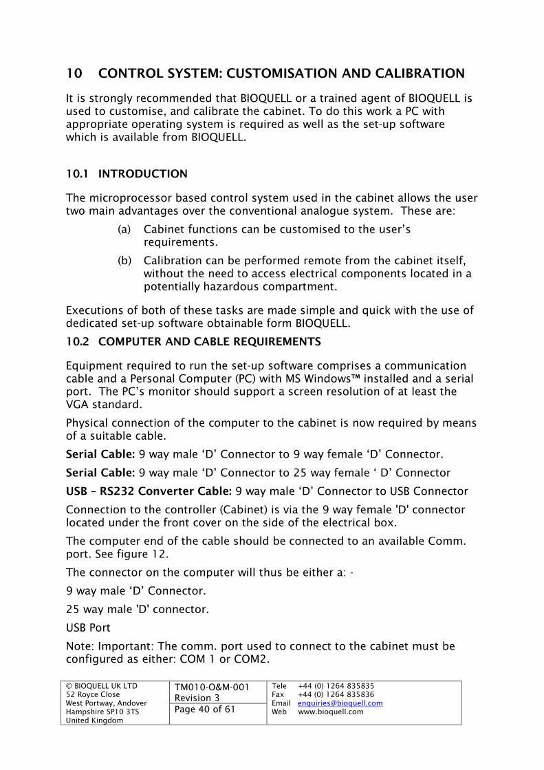
© BIOQUELL UK LTD52 Royce CloseWest Portway, AndoverHampshire SP10 3TSUnited Kingdom
TM010-O&M-001Revision 3
Tele +44 (0) 1264 835835Fax +44 (0) 1264 835836Email [email protected] www.bioquell.comPage 40 of 61
10 CONTROL SYSTEM: CUSTOMISATION AND CALIBRATION
It is strongly recommended that BIOQUELL or a trained agent of BIOQUELL isused to customise, and calibrate the cabinet. To do this work a PC withappropriate operating system is required as well as the set-up softwarewhich is available from BIOQUELL.
10.1 INTRODUCTION
The microprocessor based control system used in the cabinet allows the usertwo main advantages over the conventional analogue system. These are:
(a) Cabinet functions can be customised to the user’srequirements.
(b) Calibration can be performed remote from the cabinet itself,without the need to access electrical components located in apotentially hazardous compartment.
Executions of both of these tasks are made simple and quick with the use ofdedicated set-up software obtainable form BIOQUELL.
10.2 COMPUTER AND CABLE REQUIREMENTS
Equipment required to run the set-up software comprises a communicationcable and a Personal Computer (PC) with MS Windows™ installed and a serialport. The PC’s monitor should support a screen resolution of at least theVGA standard.
Physical connection of the computer to the cabinet is now required by meansof a suitable cable.
Serial Cable: 9 way male ‘D’ Connector to 9 way female ‘D’ Connector.
Serial Cable: 9 way male ‘D’ Connector to 25 way female ‘ D’ Connector
USB – RS232 Converter Cable: 9 way male ‘D’ Connector to USB Connector
Connection to the controller (Cabinet) is via the 9 way female 'D' connectorlocated under the front cover on the side of the electrical box.
The computer end of the cable should be connected to an available Comm.port. See figure 12.
The connector on the computer will thus be either a: -
9 way male ‘D’ Connector.
25 way male 'D' connector.
USB Port
Note: Important: The comm. port used to connect to the cabinet must beconfigured as either: COM 1 or COM2.
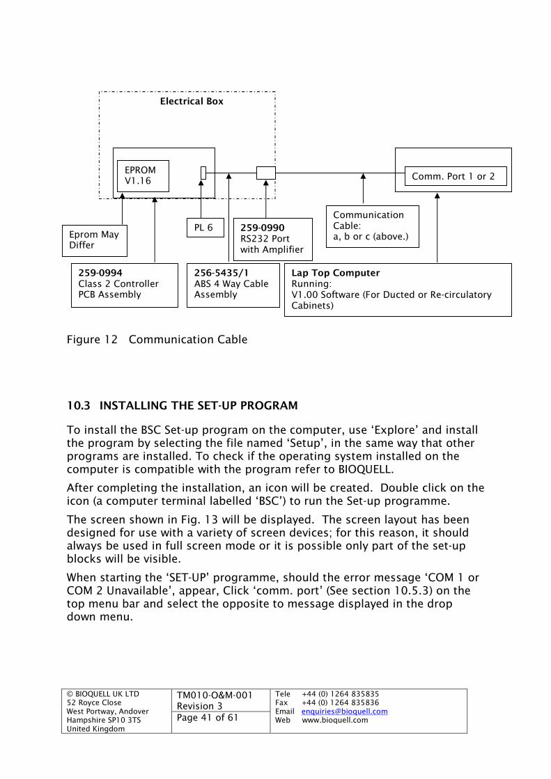
© BIOQUELL UK LTD52 Royce CloseWest Portway, AndoverHampshire SP10 3TSUnited Kingdom
TM010-O&M-001Revision 3
Tele +44 (0) 1264 835835Fax +44 (0) 1264 835836Email [email protected] www.bioquell.comPage 41 of 61
Figure 12 Communication Cable
10.3 INSTALLING THE SET-UP PROGRAM
To install the BSC Set-up program on the computer, use ‘Explore’ and installthe program by selecting the file named ‘Setup’, in the same way that otherprograms are installed. To check if the operating system installed on thecomputer is compatible with the program refer to BIOQUELL.
After completing the installation, an icon will be created. Double click on theicon (a computer terminal labelled ‘BSC’) to run the Set-up programme.
The screen shown in Fig. 13 will be displayed. The screen layout has beendesigned for use with a variety of screen devices; for this reason, it shouldalways be used in full screen mode or it is possible only part of the set-upblocks will be visible.
When starting the ‘SET-UP’ programme, should the error message ‘COM 1 orCOM 2 Unavailable’, appear, Click ‘comm. port’ (See section 10.5.3) on thetop menu bar and select the opposite to message displayed in the dropdown menu.
Lap Top ComputerRunning:V1.00 Software (For Ducted or Re-circulatoryCabinets)
CommunicationCable:a, b or c (above.)
259-0990RS232 Portwith Amplifier
256-5435/1ABS 4 Way CableAssembly
259-0994Class 2 ControllerPCB Assembly
PL 6
Comm. Port 1 or 2
Eprom MayDiffer
Electrical Box
EPROMV1.16
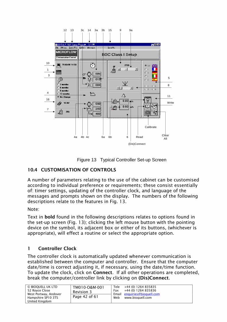
© BIOQUELL UK LTD52 Royce CloseWest Portway, AndoverHampshire SP10 3TSUnited Kingdom
TM010-O&M-001Revision 3
Tele +44 (0) 1264 835835Fax +44 (0) 1264 835836Email [email protected] www.bioquell.comPage 42 of 61
5
12 13 3c 14 3a 3b 15 9 9a
11
Write
66b4b4a
7
16
4
1
10
6a4c
(Dis)Connect
Calibrate
ClearAll
Read
8
3
Figure 13 Typical Controller Set-up Screen
10.4 CUSTOMISATION OF CONTROLS
A number of parameters relating to the use of the cabinet can be customisedaccording to individual preference or requirements; these consist essentiallyof: timer settings, updating of the controller clock, and language of themessages and prompts shown on the display. The numbers of the followingdescriptions relate to the features in Fig. 13.
Note:
Text in bold found in the following descriptions relates to options found inthe set-up screen (Fig. 13); clicking the left mouse button with the pointingdevice on the symbol, its adjacent box or either of its buttons, (whichever isappropriate), will effect a routine or select the appropriate option.
1 Controller Clock
The controller clock is automatically updated whenever communication isestablished between the computer and controller. Ensure that the computerdate/time is correct adjusting it, if necessary, using the date/time function.To update the clock, click on Connect. If all other operations are completed,break the computer/controller link by clicking on (Dis)Connect.
© BIOQUELL UK LTD52 Royce CloseWest Portway, AndoverHampshire SP10 3TSUnited Kingdom
TM010-O&M-001Revision 3
Tele +44 (0) 1264 835835Fax +44 (0) 1264 835836Email [email protected] www.bioquell.comPage 43 of 61
3 Timer Settings
The settings for the timers in 3a to 3c are changed by clicking in theappropriate box and then typing the required time. The time entered is inminutes for which the device is active. Values can range between 0 and 255minutes for the mute timer and 0 to 999 minutes for other parameters. Forfurther descriptions of the functions referenced, refer to Section 5.1 ‘ControlPanel’.
3a Overrun timer
Pressing the ‘FAN DELAY OFF’ button causes the fan to continue running forthe time period entered.
3b UV timer
Pressing the ‘UV’ button switches the UV lamp on for the time periodentered.
3c Mute timer
Pressing the ‘MUTE’ button mutes the buzzer for the time period entered.
4 Vaporiser Cycle
The vaporisation cycle consists of sequential phases, with configurabledurations of between 0 and 999 minutes. To change the settings, afterConnecting, click in the relevant box and edit as required.
If these are the only operations to be carried out, after amending the values,click on Write, followed by Disconnect.
4a On time
This is the time at the start of the cycle when the vaporiser heater ispowered. Choose a suitable time to achieve evaporation of all of thefumigant solution, but not to run the heater needlessly. A thermostat willbreak (and reset) power to the unit if the evaporation temperature isexceeded. As a guide, if 22 ml of approximately 40% solution with an equalvolume of water is being used, then 26 minutes should be an appropriatevalue for this timer.
4b Fumigation time
This is the time required for the fumigant to sterilise the cabinet internalsurfaces and all installed components. Thus, choice of an appropriate valuewill depend on the sterilising agent, its concentration, and the nature of thesource of contamination within the cabinet.
A figure of 240 minutes is suggested as a suitable value, assuming 40%solution Formaldehyde is being used.
4c Purge time
This is the time period following fumigation when the fan operates to extractthe sterilising agent out of the cabinet. Again, careful consideration needsto be given to the choice of this value since an adequate time needs to be

© BIOQUELL UK LTD52 Royce CloseWest Portway, AndoverHampshire SP10 3TSUnited Kingdom
TM010-O&M-001Revision 3
Tele +44 (0) 1264 835835Fax +44 (0) 1264 835836Email [email protected] www.bioquell.comPage 44 of 61
allowed to ensure that all traces of the material have been removed. Thefollowing points should be remembered:
(i) Although the OES (Occupational Exposure Standard) may besatisfied and the presence of the fumigant is not detected bysmell, the working area of the cabinet may still constitute ahazardous environment towards the material being processed.
(ii) Trials with the cabinet have found that concentration levels offumigant within the cabinet when subjected to purging action(exhaust ducted outside laboratory), drop rapidly initially, buta disproportionate time is required for final reductions to theacceptable level.
(iii) A value for this time of 240 minutes has been found to beappropriate to bring concentration level within the currentlypublished OES value (2 ppm). However, your Safety Officershould be consulted for definite guidance on this and othertimer settings suggested.
5 Language
The messages displayed on the controller screen are in English. The optionto select other languages is not available.
6 Alarms
The value at which alarm limits are to be calibrated are entered in the twofields 6a and 6b. On execution of a calibration process, it is the valuesentered or previously entered and stored, which the user is prompted to setin order that airflow alarms can be recorded by the controller.
The alarm values are stored as configuration files. How to Save and Loadconfiguration files is described in Section 10.5.1 ‘File’.
The fields labelled 6a and 6b refer to alarm values (in m/s) of high inflowand (low) inflow respectively. To create a configuration file click the pointerin the relevant field, press the Delete key as required and enter the desiredvalue. When all other desired parameters have been entered select Save asdescribed in Section 10.5.1.2 ‘Save’, to store the settings on the PC disk.
7 Sensor Output
Providing the Show sensors option has been selected from the Optionsmenu, the fields adjacent to the symbols will display a numericalrepresentation of the inflow sensor output values. The numbers displayed(between 0 and 255) proportionally relate, although not linearly, to theairflow over the respective sensor. Thus, observation of the values can be ofassistance during: calibration, diagnosis of faults, and commissioning.
Note:As a default, Show sensors is selected.
8 Setpoint Adjustment
© BIOQUELL UK LTD52 Royce CloseWest Portway, AndoverHampshire SP10 3TSUnited Kingdom
TM010-O&M-001Revision 3
Tele +44 (0) 1264 835835Fax +44 (0) 1264 835836Email [email protected] www.bioquell.comPage 45 of 61
This slider allows the controlled operating point of the cabinet fan’s speed tobe adjusted once calibration has been performed.
9 Fan Speed Adjustment
This control allows the speed of the main fan to be adjusted.
9a Main Fan Speed
Manual speed control of the cabinet’s main fan can be achieved by use of theslider labelled 9a in Fig. 13. Manual adjustments may be necessary when aspecific flow is required in the cabinet, but the use of this device is expectedto be limited to occasions of testing and evaluation. To use the manualspeed adjustment, the software should firstly be Connected, then manualcontrol can be enabled by clicking on Options followed by Direct Control.Note that as a default, this option is selected.
Whenever the controller and computer are (Dis)Connected, the fan willinitially operate at the speed that was previous set. The manual speedcontrol slider is a method of dictating the preliminary speed setting fromwhich achievement of the set point will be affected. Because controllingaction is necessarily quite slow, the alarms points may be checked byemploying suitable starting points for the fan and then enabling controlleraction by clicking on (Dis)Connect.
10 PC Clock
This field shows the time and date of the PC’s internal clock. It is importantthat the PC’s clock always reports the correct time and date as this is thereference used to (re)set the controller clock; whenever a connection is madebetween the two devices, the controller clock is automatically updated fromthe PC clock.
For security purposes, the controller has been programmed so that it will notaccept a time update grossly behind its current reference.
10.5 MENU BAR
Facilities available from the top menu (refer to Fig. 13) are described in thefollowing paragraphs. To display the possible options click with the pointeron the appropriate text. The available options will then be displayed in blacktext. Options not available will be shown in grey.
10.5.1 File
The Load and Save options allow sets of configurations to be stored oncomputer disc and retrieved for subsequent use. This therefore will savetime entering values each time a cabinet is set-up or a series of cabinets areto be set to operate in the same way. However, since controller sensorvalues are not stored in the configuration file, it is essential that each cabinetis calibrated using the facility described in Section 11.4 ‘CalibrationProcedure’.
© BIOQUELL UK LTD52 Royce CloseWest Portway, AndoverHampshire SP10 3TSUnited Kingdom
TM010-O&M-001Revision 3
Tele +44 (0) 1264 835835Fax +44 (0) 1264 835836Email [email protected] www.bioquell.comPage 46 of 61
10.5.1.1 Load
To load a configuration:
(a) Click on File, followed by Load.
(b) All files with extensions ‘.cfg’ will be displayed; select theappropriate by double clicking on it or type its name in the FileName box. Click on OK or alternatively double click on theappropriate directory in the Directories or Drives boxes if it isstored.
(c) All the set-up parameters will then be displayed on the screen
10.5.1.2 Save
To save a configuration:
(a) Enter all the data in the relevant fields on the set-up screen
(b) Click on File, followed by Save.
(c) Type a path and file name in the File Name box. For easymanagement, the choice of a file extension ‘.cfg’ isrecommended; this will store all files of this type together andwill display them each time a Load Settings selection is to bemade.
(d) Click on OK.
If a configuration file is to be used on more than one cabinet, it should besaved on the computer’s fixed disc. Thus the drive name and directory pathshould prefix the file name, e.g. C:\SETUPS\FILENAME.CFG. SETUPS is adirectory specifically created for the storage of configuration files andFILENAME is a name for the file which facilitates easy identification, e.g.BS_12.
10.5.1.3 Exit
The Exit option can be used as an alternative to the close window (‘-‘) buttonto terminate running of the set-up program.
10.5.2 PIN Nos.
Maintenance of the PIN numbers can be carried out by selecting PIN Nos.The PIN numbers are the four digit codes which allow the fan selections tobe locked and also allows use of the vapourisation cycle to those personswith knowledge of the applicable number. When the Connect operation hasbeen executed the following two options are available.
10.5.2.1 Read
Allows the stored codes to be interrogated and displayed in a box on thescreen.
© BIOQUELL UK LTD52 Royce CloseWest Portway, AndoverHampshire SP10 3TSUnited Kingdom
TM010-O&M-001Revision 3
Tele +44 (0) 1264 835835Fax +44 (0) 1264 835836Email [email protected] www.bioquell.comPage 47 of 61
10.5.2.2 Reset
Resets the two codes to default values.
The default values will be displayed, but for reference they are:
Fan functions locking code: 1111
Vapouriser function access code: 2222
The configuration of different codes must be carried out from the controllerkeypad once communication between controller and computer has beenbroken. To break the link, click on the (Dis)connect button.
Note:
The current status of the communication link between the PC and thecontroller is indicated by the graphic on the (Dis)Connect button. When thecommunication link is disconnected the two connectors are shownseparated; when connected they are together.
The status of the communication link should not be confused with physicalcondition of whether the cable is connected or not, e.g. the cable may beconnected but the communication link may not be made.
10.5.3 Comm Port
The Comm Port menu options allow the selection of either COM1 or COM2(serial) ports on the computer to be used for communication to thecontroller. By default, COM2 will be selected but the assignment can bechanged to COM1 by clicking on the appropriate text.
If a portable computer is used for setting up, the use of COM1 is likely to bethe only serial port available for external connections. Thus, it will benecessary to make this selection before connection to the controller can bemade.
10.5.4 Options
Selecting Options allows enabling of the following two facilities.
10.5.4.1 Direct Control
When selected, the fan speed slider (area 9 of Fig. 13) can be used to directlyadjust the Exhaust fan speed. This is useful primarily during the calibrationprocess described in the next section.
10.5.4.2 Show Sensors
When selected, numerically scaled sensor output values are displayed in area7 of Fig. 13.

© BIOQUELL UK LTD52 Royce CloseWest Portway, AndoverHampshire SP10 3TSUnited Kingdom
TM010-O&M-001Revision 3
Tele +44 (0) 1264 835835Fax +44 (0) 1264 835836Email [email protected] www.bioquell.comPage 48 of 61
10.6 MISCELLANEOUS FUNCTIONS
10.6.1 (Dis)Connect
This button serves both the functions of connecting and disconnecting thecommunication link between the PC and Controller. The current status ofthe communication link between the PC and the controller is indicated by thegraphic on the (Dis)connect button.
When the communication link is disconnected the two connectors are shownseparated, when connected they are together.
10.6.2 Read
Although all setup parameters are automatically (read from the controllerand) displayed on the screen whenever a Connection is made, Read willrepeat this function. Read is therefore used after a variable has beenchanged and written to controller memory for example, and it issubsequently required to check the controller’s current settings.
10.6.3 Calibrate
The calibrate button initiates the calibration cycle which is explained inSection 11 ‘Calibration of Airflow and Alarms’.
10.6.4 Clear all
Clicking on the Clear all button will reset all fields on the setup screen totheir default values. Commonly, default values are zero.
10.6.5 Write
The Write function will load all current screen parameters to the controllermemory.
© BIOQUELL UK LTD52 Royce CloseWest Portway, AndoverHampshire SP10 3TSUnited Kingdom
TM010-O&M-001Revision 3
Tele +44 (0) 1264 835835Fax +44 (0) 1264 835836Email [email protected] www.bioquell.comPage 49 of 61
11 CALIBRATION OF AIRFLOW AND ALARMS
11.1 INTRODUCTION
The setup software Calibrate facility allows calibration of the cabinet airflowsand alarms. This option will allow downflow and inflow alarms to be set,together with the operating speed for the cabinet. It is then this speed thatthe control system will use as a reference and always attempt to maintain.The cabinet airflow can be set up to comply with EN12469:2000 or anothercriteria and the requirements/procedures are described in the followingparagraphs. Note that re-circulatory cabinets are set-up accurately with acalibrated rig giving accurate inflow and downflow readings. Site calibrationswill always be less accurate, so it is important to double check beforealtering any settings.
11.2 EQUIPMENT REQUIRED
A hot wire anemometer or a 100mm Dia Paddle wheel anemometercan be used.
A Laboratory stand to hold the anemometer
Multimeter
Laptop Computer with V1.00 Calibration software Installed
Communication Cable see section 10.2
11.3 AIRFLOW REQUIREMENTS
The inward airflow velocity through the working aperture shall be between0.7 and 1.0 m/s.
11.4 CALIBRATION PROCEDURE
Calibration ought only to be carried out by a suitably trained Technician.The ‘Calibrate’ process will instruct the operator to set the airflow via a(virtual) slider on the screen to the two alarm velocities of: low and high InFlow. These values will then be used by the set-up software to derive anoperating condition for the cabinet such that no alarms will be activated.When the data is written to the controller, the values will be stored and useduntil the cabinet is next calibrated or adjusted. The operating condition ofthe cabinet can be manually adjusted if desired.
To calibrate the cabinet, proceed as follows:
If communication between the computer and controller is not made, click on(Dis)Connect (area 11, Fig. 13).
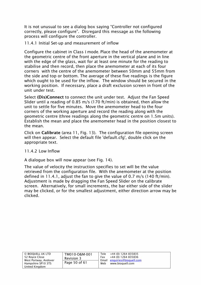
© BIOQUELL UK LTD52 Royce CloseWest Portway, AndoverHampshire SP10 3TSUnited Kingdom
TM010-O&M-001Revision 3
Tele +44 (0) 1264 835835Fax +44 (0) 1264 835836Email [email protected] www.bioquell.comPage 50 of 61
It is not unusual to see a dialog box saying “Controller not configuredcorrectly, please configure”. Disregard this message as the followingprocess will configure the controller.
11.4.1 Initial Set-up and measurement of inflow
Configure the cabinet in Class I mode. Place the head of the anemometer atthe geometric centre of the front aperture in the vertical plane and in linewith the edge of the glass, wait for at least one minute for the reading tostabilise and then record, then place the anemometer at each of its fourcorners with the centre of the anemometer between 50mm and 55mm fromthe side and top or bottom. The average of these five readings is the figurewhich ought to be used for the inflow. The window should be secured in theworking position. If necessary, place a draft exclusion screen in front of theunit under test.
Select (Dis)Connect to connect the unit under test. Adjust the Fan SpeedSlider until a reading of 0.85 m/s (170 ft/min) is obtained, then allow theunit to settle for five minutes. Move the anemometer head to the fourcorners of the working aperture and record the reading along with thegeometric centre (three readings along the geometric centre on 1.5m units).Establish the mean and place the anemometer head in the position closest tothe mean.
Click on Calibrate (area 11, Fig. 13). The configuration file opening screenwill then appear. Select the default file 'default.cfg', double click on theappropriate text.
11.4.2 Low Inflow
A dialogue box will now appear (see Fig. 14).
The value of velocity the instruction specifies to set will be the valueretrieved from the configuration file. With the anemometer at the positiondefined in 11.4.1, adjust the fan to give the value of 0.7 m/s (140 ft/min).Adjustment is made by dragging the Fan Speed Slider on the calibratescreen. Alternatively, for small increments, the bar either side of the slidermay be clicked, or for the smallest adjustment, either direction arrow may beclicked.

© BIOQUELL UK LTD52 Royce CloseWest Portway, AndoverHampshire SP10 3TSUnited Kingdom
TM010-O&M-001Revision 3
Tele +44 (0) 1264 835835Fax +44 (0) 1264 835836Email [email protected] www.bioquell.comPage 51 of 61
Figure 14 0.7 m/s, Low Inflow Alarm Setting
When the correct speed has been obtained as indicated on the anemometer,although the software waits until sensor values are stable, it is advisable toobserve the sensor values until the numbers are steady before clickingContinue.
Click on the Continue button. A new dialog box will appear, “Please wait forStabilisation” see Fig. 15. Wait until this clears, if this fails to clear within 10minutes, there is a problem with the flow sensor as it is not stabilising, seektechnical assistant.
Figure 15 “Please Wait for Stabilisation” Dialog Box
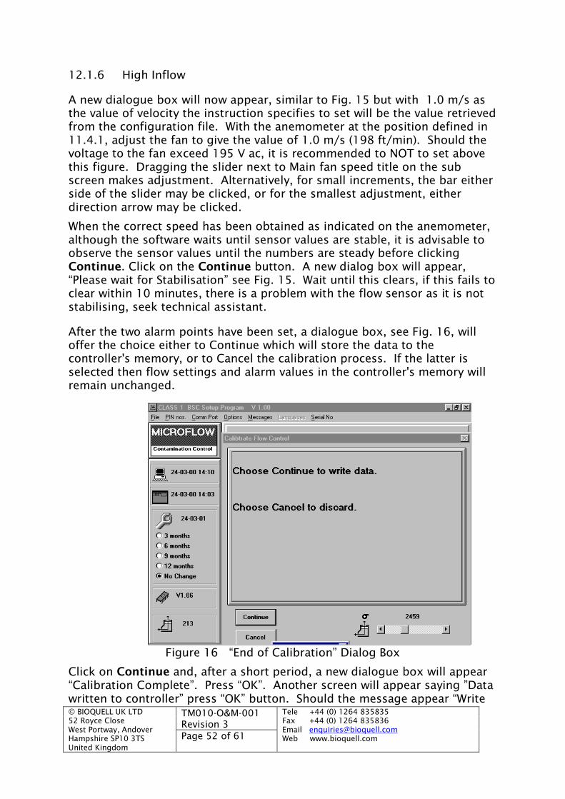
© BIOQUELL UK LTD52 Royce CloseWest Portway, AndoverHampshire SP10 3TSUnited Kingdom
TM010-O&M-001Revision 3
Tele +44 (0) 1264 835835Fax +44 (0) 1264 835836Email [email protected] www.bioquell.comPage 52 of 61
12.1.6 High Inflow
A new dialogue box will now appear, similar to Fig. 15 but with 1.0 m/s asthe value of velocity the instruction specifies to set will be the value retrievedfrom the configuration file. With the anemometer at the position defined in11.4.1, adjust the fan to give the value of 1.0 m/s (198 ft/min). Should thevoltage to the fan exceed 195 V ac, it is recommended to NOT to set abovethis figure. Dragging the slider next to Main fan speed title on the subscreen makes adjustment. Alternatively, for small increments, the bar eitherside of the slider may be clicked, or for the smallest adjustment, eitherdirection arrow may be clicked.
When the correct speed has been obtained as indicated on the anemometer,although the software waits until sensor values are stable, it is advisable toobserve the sensor values until the numbers are steady before clickingContinue. Click on the Continue button. A new dialog box will appear,“Please wait for Stabilisation” see Fig. 15. Wait until this clears, if this fails toclear within 10 minutes, there is a problem with the flow sensor as it is notstabilising, seek technical assistant.
After the two alarm points have been set, a dialogue box, see Fig. 16, willoffer the choice either to Continue which will store the data to thecontroller's memory, or to Cancel the calibration process. If the latter isselected then flow settings and alarm values in the controller's memory willremain unchanged.
Figure 16 “End of Calibration” Dialog Box
Click on Continue and, after a short period, a new dialogue box will appear“Calibration Complete”. Press “OK”. Another screen will appear saying ”Datawritten to controller” press “OK” button. Should the message appear “Write
© BIOQUELL UK LTD52 Royce CloseWest Portway, AndoverHampshire SP10 3TSUnited Kingdom
TM010-O&M-001Revision 3
Tele +44 (0) 1264 835835Fax +44 (0) 1264 835836Email [email protected] www.bioquell.comPage 53 of 61
failed, try again” with two buttons “Yes” and “No”. This message does notnecessarily mean that it has actually failed. Press “NO”
Calibration is now complete break the communication link between the PCand controller by clicking (Dis)Connect button.
Note:
If new setup parameters (different from configuration files already stored onthe PC’s disk) are required to be saved for future use, this operation shouldbe carried out before (Dis)Connecting. To save a configuration file, edit allvariables to the figures required on the screen then execute the fileinterface. Finally, click on Save. For further details see Section 10.5.1 ‘File’.
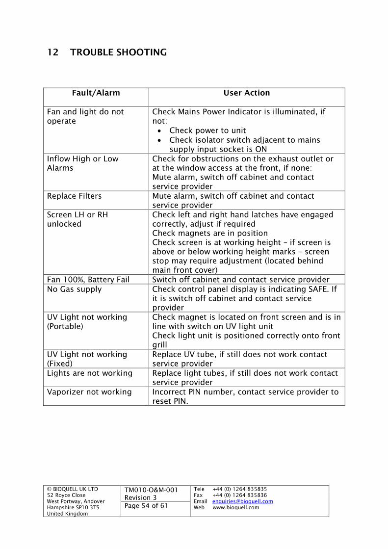
© BIOQUELL UK LTD52 Royce CloseWest Portway, AndoverHampshire SP10 3TSUnited Kingdom
TM010-O&M-001Revision 3
Tele +44 (0) 1264 835835Fax +44 (0) 1264 835836Email [email protected] www.bioquell.comPage 54 of 61
12 TROUBLE SHOOTING
Fault/Alarm User Action
Fan and light do notoperate
Check Mains Power Indicator is illuminated, ifnot: Check power to unit Check isolator switch adjacent to mains
supply input socket is ONInflow High or LowAlarms
Check for obstructions on the exhaust outlet orat the window access at the front, if none:Mute alarm, switch off cabinet and contactservice provider
Replace Filters Mute alarm, switch off cabinet and contactservice provider
Screen LH or RHunlocked
Check left and right hand latches have engagedcorrectly, adjust if requiredCheck magnets are in positionCheck screen is at working height – if screen isabove or below working height marks – screenstop may require adjustment (located behindmain front cover)
Fan 100%, Battery Fail Switch off cabinet and contact service providerNo Gas supply Check control panel display is indicating SAFE. If
it is switch off cabinet and contact serviceprovider
UV Light not working(Portable)
Check magnet is located on front screen and is inline with switch on UV light unitCheck light unit is positioned correctly onto frontgrill
UV Light not working(Fixed)
Replace UV tube, if still does not work contactservice provider
Lights are not working Replace light tubes, if still does not work contactservice provider
Vaporizer not working Incorrect PIN number, contact service provider toreset PIN.

© BIOQUELL UK LTD52 Royce CloseWest Portway, AndoverHampshire SP10 3TSUnited Kingdom
TM010-O&M-001Revision 3
Tele +44 (0) 1264 835835Fax +44 (0) 1264 835836Email [email protected] www.bioquell.comPage 55 of 61
13 SPARES
Refer to the Supplier or the Maintenance Provider for a comprehensive list ofspares. Below are the most common parts requested:
MODEL ABS 1000 ABS 1200 ABS 1500
Main Filter MSABS1000-031
MSABS1200-031
MSABS1500-031
Integral Bypass Filter MSABS1000-030
MSABS1200-030
MSABS1500-030
Electronic Ballast H12010020 H12010016 H12010021
Light Tubes H12010018 H12010015 H12010019
UV Tubes 262-5005 262-5004 262-5004
Gas Springs 754-1023 754-1026 754-1022
Door Seal TM021-0014 TM022-0014 TM025-0014
ITEM QTY. USED DESCRIPTION PART No.
Main Fan (230V) (Recirc) 1 Motor Fan Unit complete with Capacitors 450-2050
Exhaust Fan Unit 1 Fan at end of duct (standard version) AMM20663E/W
Starters for UV 1 Starter 257-0381
Fuses 2 10 A Antisurge 271-4719
Fuses 3 6.3 A Quick Blow EHB 10342 E
Fuses 1 2 A Antisurge EHB 10374 E
Fuses 2 1 A Quick Blow EHB 10437 E
Fuses 1 100 mA Antisurge EHB 10174 E
Fuses 1 1 A Antisurge EHB 10440 E
Circuit Breakers 1 Double Pole Circuit Breaker/Switch (2.5 A) 250-0010
ABS PCB 1 Main circuit board 259-0994
ABS Top Box Duct Spigot 1 Duct Spigot TM029-0003
SPARES LIST - AUTOMATIC FUMIGATION SYSTEM
ITEM QTY. USED DESCRIPTION PART No.
Filter 1 Carbon ABS 013
Fan 1 230 V 50 Hz 450-2053
Valve Flap 2 Rubber 550-9000
Valve Solenoid 2 230 V 50 Hz 3225-100001
© BIOQUELL UK LTD52 Royce CloseWest Portway, AndoverHampshire SP10 3TSUnited Kingdom
TM010-O&M-001Revision 3
Tele +44 (0) 1264 835835Fax +44 (0) 1264 835836Email [email protected] www.bioquell.comPage 56 of 61
14 SERVICING RECORD
DATE ACTION COMPLETED BY
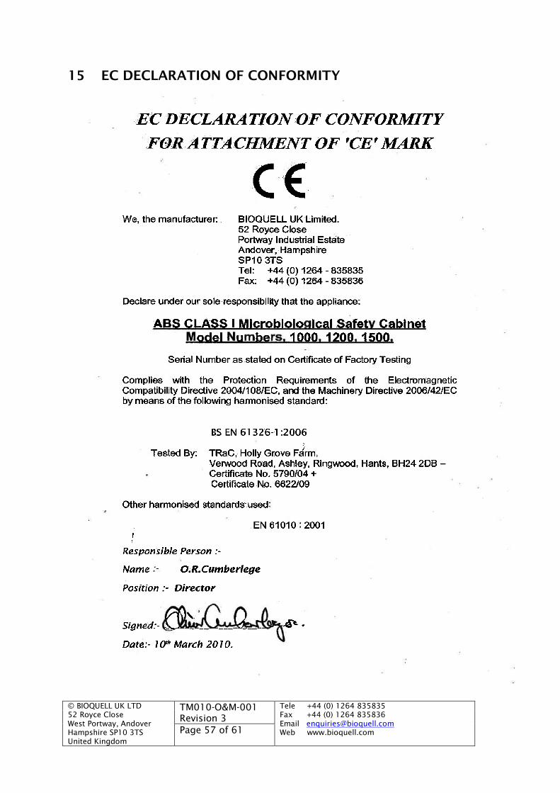
© BIOQUELL UK LTD52 Royce CloseWest Portway, AndoverHampshire SP10 3TSUnited Kingdom
TM010-O&M-001Revision 3
Tele +44 (0) 1264 835835Fax +44 (0) 1264 835836Email [email protected] www.bioquell.comPage 57 of 61
15 EC DECLARATION OF CONFORMITY

© BIOQUELL UK LTD52 Royce CloseWest Portway, AndoverHampshire SP10 3TSUnited Kingdom
TM010-O&M-001Revision 3
Tele +44 (0) 1264 835835Fax +44 (0) 1264 835836Email [email protected] www.bioquell.comPage 58 of 61
16 APPROVED SERVICE COMPANY
We only recommend BIOQUELL, in the UK or its local service provider to carryout service and repair work. These technicians have been fully trained on theproduct.
To contact BIOQUELL use one of the following methods:
Call the Service Desk on 01264 835 800 or 0800 527800
Fax to 01264 835 801
E-mail to [email protected]
For details of our local service providers outside the UK contact BIOQUELL on+44 1264 835 800
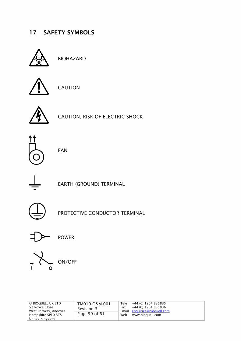
© BIOQUELL UK LTD52 Royce CloseWest Portway, AndoverHampshire SP10 3TSUnited Kingdom
TM010-O&M-001Revision 3
Tele +44 (0) 1264 835835Fax +44 (0) 1264 835836Email [email protected] www.bioquell.comPage 59 of 61
17 SAFETY SYMBOLS
BIOHAZARD
CAUTION
CAUTION, RISK OF ELECTRIC SHOCK
FAN
EARTH (GROUND) TERMINAL
PROTECTIVE CONDUCTOR TERMINAL
POWER
ON/OFF
OI
© BIOQUELL UK LTD52 Royce CloseWest Portway, AndoverHampshire SP10 3TSUnited Kingdom
TM010-O&M-001Revision 3
Tele +44 (0) 1264 835835Fax +44 (0) 1264 835836Email [email protected] www.bioquell.comPage 60 of 61
18 WARRANTY
BIOQUELL UK Ltd. produces products that are warranted under normal usageagainst defects in workmanship and materials for one-year parts and labourcosts, from the date of manufacture. The Warranty is stated in the StandardTerms and Conditions of sale.
Export and Agent retailed products are warranted directly by the Agent.Please confirm your warranty and liability status with the Agent.
In addition, the Warranty is void unless the following conditions are met:
(a) The product has been installed and used as stated within theInstruction Manual.
(b) TThhee wwaarrrraannttyy ddooeess NNOOTT iinncclluuddee sseerrvviicciinngg oorr mmaaiinntteennaannccee.. Anapproved service company who have attended our training courses foryour product must carry out maintenance of product. Failure tomaintain or service this product will invalidate the warranty.Maintenance must be carried out in accordance with the ServiceManual and include tasks within stated periods. Failure to useapproved service companies or BIOQUELL UK Ltd. trained personnel formaintenance also affects the CE Marking status of the product,removing BIOQUELL’s Duty of Care and responsibility
(c) Consumables such as: pre-filters, HEPA filters, light bulbs and tubes,not warranted.
(d) This Warranty is void if faults are caused by accidental damage,mishandling, adjustment by unauthorised personnel or failure tofollow the correct maintenance and safety precautions as stated in theInstruction Manual.
(e) The Warranty expressly provided for herein is the sole Warrantyprovided in connection with the product and no other Warranty,expressed or implied, is provided. BIOQUELL UK Ltd. assumes noresponsibility for any other claims, consequential (including lost timeor profit) or other damage, whether based in contract, tort orotherwise, not specifically stated in this Warranty.
(f) Except in respect of death or personal injury caused by Seller’snegligence, or as expressly provided in these Conditions, Seller shallnot be liable to Buyer by reason of any representation (unlessfraudulent), or any implied warranty, condition or other term, or anyduty at common law, or under the express terms of the Contract forany loss of profit or any indirect, special or consequential loss,damage, costs, expenses or other claims (whether caused by thenegligence of Seller, its servants or agents or otherwise) which ariseout of or in connection with the supply of the Goods or their use orresale by Buyer, and the entire liability of Seller under or in connectionwith the Contract shall not exceed the price of the Goods.
© BIOQUELL UK LTD52 Royce CloseWest Portway, AndoverHampshire SP10 3TSUnited Kingdom
TM010-O&M-001Revision 3
Tele +44 (0) 1264 835835Fax +44 (0) 1264 835836Email [email protected] www.bioquell.comPage 61 of 61
Note:When requesting a Warranty visit, please have the followinginformation available:
(i) Product model number and name.
(ii) Serial number.
(iii) Date of last service, and Service Company.
(iv) Nature of fault and any other comments likely to indicate cause offault.
(v) A Purchase Order number to cover costs incurred if visit is outsidethe scope of the Warranty.
BIOQUELL UK Ltd., or other nominated personnel will carry outwarranty visits.
(g) In the event of any health and safety incidents please advise us inwriting at the earliest opportunity.
(h) This warranty and all other contractual issues shall be governed byEnglish law and the parties agree to submit to the nonexclusivejurisdiction of the courts of England.