tnc-pi assembly instructions & operating tips · tnc-pi assembly instructions & operating...
TRANSCRIPT

TNC-Pi User Guide -1- 6/6/2018
TNC-Pi Assembly Instructions & Operating Tips
By John Hansen, W2FS
Portions by
John Wiseman, G8BPQ – Linux configuration
Jim Whiteside, M0HPJ – Xastir
Document editing support by
Ed Slingland, N2WD
Website
http://tnc-x.com/TNCPi.htm
TNC-Pi User Guide -2- 6/6/2018
Contents
Introduction ................................................................................................... 3
Assembly Instructions ..................................................................................... 4
Parts List ............................................................................................................... 4
Assembly ............................................................................................................... 6
Parts Layout ......................................................................................................... 11
Connecting the Radio .................................................................................... 12
Adjust transmit audio output .................................................................................. 13
Set the transmit delay ........................................................................................... 13
Configuring the Raspberry Pi .......................................................................... 13
Keyboard to Keyboard Connections ......................................................................... 14
Support ....................................................................................................... 16
Application Notes .......................................................................................... 16
Using Xastir ......................................................................................................... 16
Update the package list .................................................................................................. 16
Then install Xastir .......................................................................................................... 17
Kill kissattach ............................................................................................................. 17
Start Xastir ................................................................................................................... 17
Running Xastir ............................................................................................................... 18
More information ........................................................................................................... 18
Configuring TNC-Pi for Use with the I2C Protocol ...................................................... 18
Setup ........................................................................................................................... 18
Get and set parameters .................................................................................................. 19
Running Applications other than LinBPQ with TNC-Pi in I2C mode. .............................. 20

TNC-Pi User Guide -3- 6/6/2018
Introduction
Thank you for purchasing a TNC-Pi: TNC-X for Raspberry Pi or TNC-Pi 2.
Figure 1: Two TNC-Pi’s stacked on one Raspberry Pi
Figure 2: TNC-Pi mounted on a Raspberry Pi
Figure 3: TNC-Pi 2 mounted on a Raspberry Pi 2.
TNC-Pi User Guide -4- 6/6/2018
Assembly Instructions
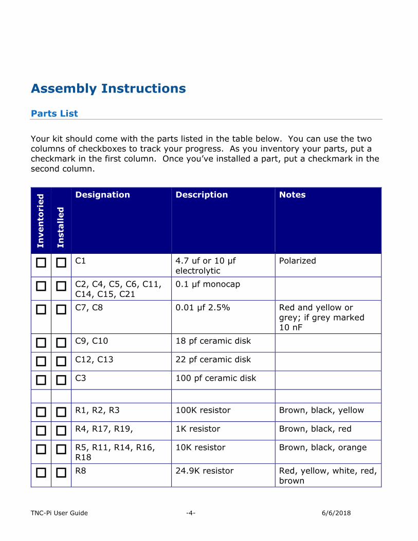
Parts List
Your kit should come with the parts listed in the table below. You can use the two columns of checkboxes to track your progress. As you inventory your parts, put a
checkmark in the first column. Once you’ve installed a part, put a checkmark in the
second column.
In
ven
torie
d
In
sta
lled
Designation Description Notes
C1 4.7 uf or 10 µf
electrolytic
Polarized
C2, C4, C5, C6, C11,
C14, C15, C21
0.1 µf monocap
C7, C8 0.01 µf 2.5% Red and yellow or
grey; if grey marked 10 nF
C9, C10 18 pf ceramic disk
C12, C13 22 pf ceramic disk
C3 100 pf ceramic disk
R1, R2, R3 100K resistor Brown, black, yellow
R4, R17, R19, 1K resistor Brown, black, red
R5, R11, R14, R16, R18
10K resistor Brown, black, orange
R8 24.9K resistor Red, yellow, white, red,
brown

TNC-Pi User Guide -5- 6/6/2018
R9 9.31K resistor White, orange, brown, brown, brown
R10 18.7K resistor Brown, grey, purple, red, brown
R6, R7 10K trimmer potentiometer
Orange or Blue
X1 3.57 MHz crystal
X2 20.00 MHz crystal
D4 Red LED (PTT) Polarized
D5 Yellow LED (DCD) Polarized
Q1 PN2222 transistor 3 pin, flat side (don’t
confuse with U1)
U1 MCP1700-33 or
MCP1700-30 Regulator
3 pin, flat side
U2 CML MX-614 Modem 16 pin IC
U3 PIC16F1847
microcontroller
18 pin IC
U4 MCP6023 Op Amp 8 pin IC
U5 23K640 Memory 8 pin IC
IC Sockets For U2, U3, U4, U5 One 16-pin, one 18-pin
and two 8-pin sockets
JP3, JP4 2-pin header Not included in newer kits
Combined into one 2x2 pin header
2 x 13 extra long
header 2 x 20 in TNC-Pi 2

TNC-Pi User Guide -6- 6/6/2018
9 Pin D-Sub connector
Printed Circuit Board
2 shorting jumpers Not included in newer kits
Assembly
Note: John McDonough has published a number of high quality photos of
various stages in the assembly process. See
http://www.qsl.net/wb8rcr/BuildingTheTNC-Pi.html
Start by installing the parts that lie flat on the board. This includes:
a. all of the 0.1uf monocaps and
b. all of the resistors except for R6 and R7.
R10 and R11 have pads that are rather close together. Be careful
that you do not accidently create a solder bridge between them. Note that all of the components except for the 26 ( or 40 in TNC-Pi 2) pin
header are installed on the side of the board with the silk screen.
Next install the two crystals.
Ensure that the 20 MHz crystal is the one nearest the 18 pin IC.
Next install the IC sockets. Ensure that the notch on the socket lines up with the notch on the IC outline
on the PC board.
Do not plug the chips into the sockets at this point.
Next install the rest of the capacitors.
With C1, make sure that the longer lead is placed in the hole marked with a
+.
Next install the two potentiometers (R6 and R7). You may find these to be a
bit of a tight fit. If so, take a pair of needle nose pliers and flatten the leads
before inserting them into the board.

TNC-Pi User Guide -7- 6/6/2018
Next install the two LEDs. Ensure the shorter leads on the LEDs go through the holes closest to the flat
side of the LED outline.
The LEDs can be installed with bent legs so the LEDs point toward the front
of the board. This makes them easier to see when TNC-Pis are stacked one
on top of the other.
Install the transistor.
Ensure you are installing the transistor rather than the voltage regulator…
they look a lot alike.
Now install the voltage regulator.
It goes in the three holes above C1. Install it so that the flat side of the
regulator faces away from U3.
Now install the 9 pin D-Sub connector. Ensure that you push it all the way in so that it is flush against the board. In
addition to soldering the pins, you’ll gain mechanical stability by soldering
the pins that go into the large round holes on the sides of the connector.
Note: The D-Sub connector is optional. You can install the Radio
header to connect your radio to the TNC-Pi instead. See the section,
Connecting the Radio, for more information.
Solder in the 2 x13 header. With the TNC-Pi 2 kit this is a 2 x 20 header. This part is somewhat tricky. It is the only part that is installed through the
bottom of the board.
a. Start by installing this jumper on your Raspberry Pi and then
b. Lower the TNC-Pi board onto the connector so that the body of the
connector is on the BOTTOM of the TNC-Pi board.
c. Now you’ll need to solder the board about a half millimeter from all the way down in order to prevent the board from bumping into the USB
connector on the Pi. It is not necessary to solder all of the pins. You should at least solder the 4 pins in the corners (for stability) and the
first five pins on each row (pins 1 – 10).
Your best bet is to carefully trim the solder leads on the part of the TNC-Pi board that will be on the USB connector side of the Pi to get as much
clearance as possible. You might also want to put a piece of insulating tape

TNC-Pi User Guide -8- 6/6/2018
on top of the USB connector just to be on the safe side. You can then solder
the pins that come through the top of the board.
These pins will allow you to stack a second TNC-Pi on top of the first one if
you choose to do so.
Now install the 2 x 2 jumper (JP3 and JP4). If your board has a JP7 location, also take a short piece of wire and solder it in here to make a
permanent jumper. Note: If you are building a TNC-Pi 2, none of these
jumpers are needed or included in the kit. If you are building a newer kit from the original version JP3 and JP4 will also be missing, but you may need
to put a wire across JP7.
I’ve included 2 4-40 screws and a 5/8” spacer. If you have one of the
Raspberry Pi Rev. B and the original TNC-Pi kit, or if you have the Rev. B+ or Pi 2 and the TNC-Pi 2 kit, you can use this to provide some additional
mechanical stability by putting it between the hole in the Pi and the hole in
the TNC-Pi. If you have a Pi B+ board and the original TNC-Pi kit, these parts are not needed. There will be plenty of mechanical support from the
extra USB jacks on the Pi board, but you will want to use insulating tape on
these jacks to keep them from shorting the TNC board.
If you are stacking 2 or more TNC’s you might also find it preferable to use a spacer that is a male to female, rather than female to female. These male to
female spacers are available on the TNC-Pi website.
Now install jumpers at JP4 and JP3.
They should be installed so they are parallel to the body of the 2x13 pin connector. If you are building a TNC-Pi 2 or newer original TNC-Pi, none of
these jumpers are needed or included in the kit.
Leave the board connected to the Raspberry Pi and power up the Pi. Check the voltage between pin 5 (negative) and pin 14 (positive) on
U3. It should read about 3.3 volts. With the notch at the top of the chip, these pins are the ones half way down the left side (negative)
and right side (positive) of the chip.
If the voltage check is not successful, find and fix the fault before
proceeding.
Power down the Pi and remove the TNC-Pi board from the Pi,
then install the 4 ICs.
You may wish to bend the pins of the four ICs slightly inward to facilitate
inserting them into their sockets.

TNC-Pi User Guide -9- 6/6/2018
Ensure the notch on the top of each chip lines up with the notch printed on the PC board. Also make absolutely certain that you do not mix up the two 8
pin chips and plug them into the wrong sockets.
Note: Nothing will be installed at the 6 pins marked ICSP or the pins
marked J.
Congratulations, you’re done assembling the TNC-Pi.

TNC-Pi User Guide -10- 6/6/2018
Schematic Diagram
(see next page for parts layout diagram)

TNC-Pi User Guide -11- 6/6/2018
Parts Layout (for TNC-Pi)

TNC-Pi User Guide -12- 6/6/2018
Parts Layout (for TNC-Pi 2)
Connecting the Radio
You can either wire up a 9 pin D-Sub plug to mate with the one on the TNC-Pi, or, if you’d prefer, you can use the four holes below R7 labeled Radio to hard wire a radio
connection. (No header is provided in the kit for this.)
If you use the 9 pin D-Sub connection, it should be wired as follows:
Pin 1 (the square pad): TX Audio Pin 3: Push to Talk (PTT)
Pin 5: Receive Audio Pin 6: Ground
If you are using the holes marked “Radio” the connections should be: Pin 1 (the square pad): Receive Audio
Pin 2: Ground

TNC-Pi User Guide -13- 6/6/2018
Pin 3: TX Audio
Pin 4: Push to Talk (PTT)
Adjust transmit audio output
Potentiometer R7 adjusts the level of the transmit audio output. Most people will
find that they need to set it fairly near the minimum setting.
One way to set this is to use two radios, one to monitor the transmitted signal and
the other connected to the TNC-Pi.
1. Key the radio connected to the TNC-Pi manually by pushing the PTT button on
it.
2. On the other radio you will hear a continuous tone (even though no data is being transmitted… you don’t need to be running any software on the
Raspberry Pi to do this).
3. Turn R7 all the way down and the tone will go away.
4. Then slowly turn it up until the volume doesn’t increase any further in the
monitor receiver.
5. When you reach this point, back it off just a little and you should have it about
right.
Set the transmit delay
The transmit delay (TXDelay) can be set either in software or using R6. The default is to set it in software. To change the TXDelay parameter, you'll need to use the
pitnc_setparams program as explained below in the section, Using Xastir.
If you set the value of TXDelay to 0 using the pitnc_setparams program, you can
then use R6 to set the TXDelay.
Most users will find the default setting for TXDelay to be just fine.
Configuring the Raspberry Pi
The following instructions were based on a downloaded image of the “Stretch” version of the operating system. I did this by downloading Raspbian, not NOOBs.
It might be a good idea to make sure your Pi operating system is up to date. You
can do this from the command line by entering the following (this assumes you
have either hard wired or wireless network connectivity):
TNC-Pi User Guide -14- 6/6/2018
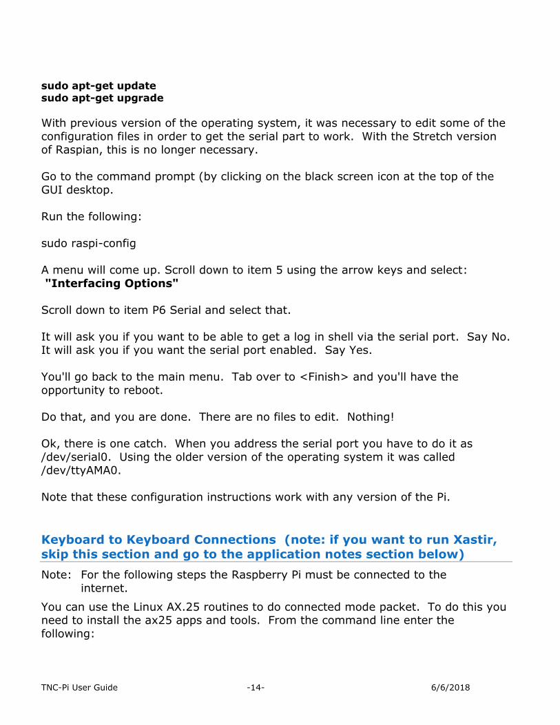
sudo apt-get update sudo apt-get upgrade
With previous version of the operating system, it was necessary to edit some of the
configuration files in order to get the serial part to work. With the Stretch version of Raspian, this is no longer necessary.
Go to the command prompt (by clicking on the black screen icon at the top of the
GUI desktop.
Run the following:
sudo raspi-config
A menu will come up. Scroll down to item 5 using the arrow keys and select:
"Interfacing Options"
Scroll down to item P6 Serial and select that.
It will ask you if you want to be able to get a log in shell via the serial port. Say No. It will ask you if you want the serial port enabled. Say Yes.
You'll go back to the main menu. Tab over to <Finish> and you'll have the
opportunity to reboot.
Do that, and you are done. There are no files to edit. Nothing!
Ok, there is one catch. When you address the serial port you have to do it as
/dev/serial0. Using the older version of the operating system it was called /dev/ttyAMA0.
Note that these configuration instructions work with any version of the Pi.
Keyboard to Keyboard Connections (note: if you want to run Xastir,
skip this section and go to the application notes section below)
Note: For the following steps the Raspberry Pi must be connected to the
internet.
You can use the Linux AX.25 routines to do connected mode packet. To do this you need to install the ax25 apps and tools. From the command line enter the
following:
TNC-Pi User Guide -15- 6/6/2018
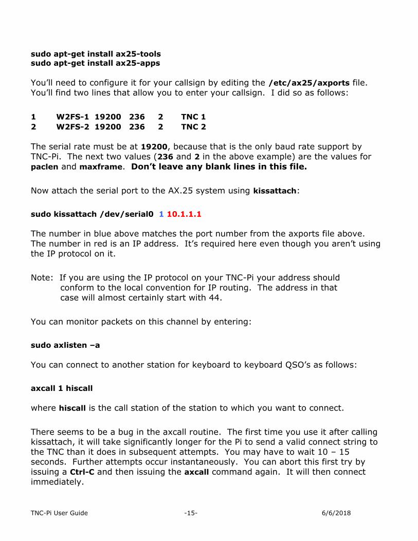
sudo apt-get install ax25-tools sudo apt-get install ax25-apps
You’ll need to configure it for your callsign by editing the /etc/ax25/axports file.
You’ll find two lines that allow you to enter your callsign. I did so as follows:
1 W2FS-1 19200 236 2 TNC 1
2 W2FS-2 19200 236 2 TNC 2
The serial rate must be at 19200, because that is the only baud rate support by
TNC-Pi. The next two values (236 and 2 in the above example) are the values for
paclen and maxframe. Don’t leave any blank lines in this file.
Now attach the serial port to the AX.25 system using kissattach:
sudo kissattach /dev/serial0 1 10.1.1.1
The number in blue above matches the port number from the axports file above.
The number in red is an IP address. It’s required here even though you aren’t using
the IP protocol on it.
Note: If you are using the IP protocol on your TNC-Pi your address should
conform to the local convention for IP routing. The address in that
case will almost certainly start with 44.
You can monitor packets on this channel by entering:
sudo axlisten –a
You can connect to another station for keyboard to keyboard QSO’s as follows:
axcall 1 hiscall
where hiscall is the call station of the station to which you want to connect.
There seems to be a bug in the axcall routine. The first time you use it after calling kissattach, it will take significantly longer for the Pi to send a valid connect string to
the TNC than it does in subsequent attempts. You may have to wait 10 – 15 seconds. Further attempts occur instantaneously. You can abort this first try by
issuing a Ctrl-C and then issuing the axcall command again. It will then connect
immediately.

TNC-Pi User Guide -16- 6/6/2018
If you are having trouble getting the TNC to respond to these commands from the serial port, you can check to see if it is working by using the pitnc_getparams
program. You can download this program from www.tnc-x.com/params.zip. If you have run KISSATTACH, make sure that it is not (rebooting is the easiest way to do
this). Unzip the file and change the permissions so that anyone can execute it (the is most easily done from the file manager in the GUI interface). Then go to the
command line, switch to the directory that the program is in and type:
./pitnc_getparams serial0 0
If a menu comes up you will know that the TNC-Pi is communicating with the Pi.
Support
If you have any questions about your TNC-Pi or are having hardware issues with it, please contact John Hansen, W2FS at [email protected]. Software issues,
particularly with regard to the Linux version of BPQ are best addressed to the
author, John Wiseman, G8BPQ.
Additional information can be found on the TNC-Pi website: http://tnc-
x.com/TNCPi.htm
The configuration programs setparams and getparams are available here:
www.tnc-x.com/pitnc.zip
Application Notes
Using Xastir
Thanks to M0HPJ for the following information
Another popular packet program that works well on the Pi is the APRS program
Xastir.
Note: For the following steps the Raspberry Pi must be connected to the
internet.
Update the package list
To install Xastir from the command line, first update the package list as follows:

TNC-Pi User Guide -17- 6/6/2018
sudo apt-get update
Then install Xastir sudo apt-get install xastir
Kill kissattach
If you have been using the AX25 apps, you’ll need to unload kissattach before
Xastir will work. You can do this by simply rebooting the Pi, or you can kill the kissattach process from the command line. To do the latter, first find out what
process number it is by using a ps command to list running processes:
ps –A|grep kissattach
Inspect the list to see the process number of the kissattach process, then kill the process using the kill command. For example, if the process number is 2335, issue
the command:
sudo kill 2335
At this point it may be a good idea to rerun the ps command to be certain that the
kissattach process was successfully killed.
Note: If you have not been using the AX25 apps, it is still necessary to edit
the cmdline.txt and inittab files as described in the section on
configuring the Pi.
Start Xastir
You can start Xastir simply by typing Xastir at the command line. The first time you
run Xastir you’ll be asked to put in your station parameters. Then you’ll need to specify the port that the TNC-Pi is on. Click on Interface and then Interface Control.
Click “Add” and pick “Serial KISS TNC” off the list. Push Add and it will bring up a
properties list. Under TNC Port enter:
/dev/serial0
TNC-Pi User Guide -18- 6/6/2018
Running Xastir Everything else is pretty self-explanatory. Do make sure you change the baud rate
to 19200. This is not the default. You can select “Maps” and the Map Chooser to select a better set of maps than the default. If you currently have internet
connectivity, one of the cloud map options is probably best. If you select a new map option, you should deselect the old one. I haven’t yet explored the option of
caching the maps to the local SD card so that I don’t need an Internet connection,
but I expect to look into that soon.
More information
A much more detailed discussion of running Xastir on the Pi in a mobile environment is contained in a paper presented at the 2013 ARRL/TAPR Digital Communications
Conference. It can be found at:
http://www.tnc-x.com/DCC2013.doc.
Note: In this paper I discussed using maps that were available from Cloudmade.
Since the time that this paper Cloudmade has discontinued free access to these maps. However, the same maps are available from the following source:
http://download.geofabrik.de
The procedure for obtaining and using the maps is the same as those referenced in the paper for Cloudmade.
Configuring TNC-Pi for Use with the I2C Protocol
The TNC-Pi can be configured to communicate with the Raspberry Pi using the I2C
protocol. To configure the TNC-Pi for I2C, you will need a configuration programs pi_tncsetparams and pi_tncgetparams. The getparams program reads the
parameters from the TNC-Pi while the setparams program allows you to set them.
These programs are available at:
www.tnc-x.com/pitnc.zip
Setup
Before using them, however, it will be necessary to make some additional configuration changes to the Pi. First, make the following changes to the following
files:
1. In the /etc/modprobe.d/raspi-blacklist.conf file,
remove the line: blacklist I2C-bcm2708
2. In the etc/modules file,
add the line: i2c-dev

TNC-Pi User Guide -19- 6/6/2018
Get and set parameters
Note: Before running the getparams and setparams programs, ensure that
kissattach is not running.
The pitnc_getparams program lists the values for all of the user-settable
parameters. Its syntax is:
pitnc_getparams b d
where:
b is the number of the I2C bus and
d is the number of the I2C device on that bus.
TNC-Pi is shipped with both of these parameters set to 0. An I2C device number of
0 means the TNC is using the serial port rather than the I2C port.
The pitnc_setparams program writes values to the TNC-Pi. Its syntax is:
pitnc_setparams b d p v
where
once again b and d are the bus and device,
p is the parameter number (1 – 7) and
v is the new parameter value.
The parameters that you are most like to use are:
Parameter
value
Description Notes
1 Sets the TXDelay
With TNC-Pi, you can set the TXDelay either in software using the pitnc_setparams program or in
hardware using R6. Setting this parameter to 0
causes the TNC-Pi R6 potentiometer to determine
the value.
7 Sets the I2C
address
Setting this to 0 causes data communication on the serial port (default), any other value up to 63 will
cause I2C to be used with the TNC using this address. This permits you to use multiple TNC’s
with the same Raspberry Pi.

TNC-Pi User Guide -20- 6/6/2018
The BPQ software for Raspberry Pi is currently in beta and can be found at:
http://www.tnc-x.com/InstallingLINBPQ.htm If you ever need to reset these parameters to their original factory values, this can be done by powering down, turning the TXDelay potentiometer all the way to
minimum and then powering back up. You should see the yellow LED flash once per second. When you see it flash, you’ll know that the parameters have all been
reset. The power the device back down, move the TXDelay off of minimum and power the device back up.
Running Applications other than LinBPQ with TNC-Pi in I2C mode.
John Wiseman, G8BPQ, sends along the following information about running other
applications using I2C:
The TNC-Pi can be used with applications that use the Linux ax.25 stack, or
applications that expect to see a KISS TNC on a serial port. Program I2ckiss
converts the I2C protocol to a standard KISS presentation on a virtual serial (pty)
port. It is available here:
www.tnc-x.com/i2ckiss.zip
One copy is run for each TNC-Pi. The first two parameters to I2ckiss are I2C bus,
I2C device. If using the kernel ax.25 code, then specify the port number (from
axports) and the ip address. To use with other software, specify symlink and a
symbolic name - I suggest com1 - com255
For example, to use with the Linux ax.25 stack:
sudo ./i2ckiss 0 16 1 10.1.1.1
i2ckiss will create a pty pair, and execute kissattach on the slave half, using the 3rd
and 4th parameters
To use with a KISS application
./i2ckiss 0 16 symlink com1
i2ckiss will create a pty pair, then create a symlink to com1. The application
would then be configured to use port com1.
Note: On Version 1 Pi boards (without mounting holes) the I2C bus number
is zero, for the Version 2 boards it is 1.