heidenhainwebsystem.gismo.se/gismo/files/859/859.heidenhain.pdf · heidenhain tnc programming notes...
TRANSCRIPT

Heidenhain
TNC410/426ConversationalProgramming
ArrowSabreLancer
TNC BASIC 01/01/2001

Index1.0
2.0
3.0
4.0
5.0
6.0
7.0
8.0
9.0
10.0
11.0
12.0
13.0
14.0
15.0
Keys……………………………………………………………….
Introduction & M codes…..……………………………………
Absolute & Incremental Scale………………………………..
Cutter Compensation (APPR & DEP).………………………
Program start ……………………………………………………Toolchange………………………………………Linear programming……………………………Blend Radius & Chamfers………………….…
Circular Programming……….…………………………………
Working Planes & Polar Programming…………………….
Hole canned cycles……………………………………………..
Milling canned cycles…………………………………………..
Co-ordinate Transformations…………………………………
Sub-Programming……...……………………………………….
Helical……………………………………………………………..
Tool Setting.……………………………………………………..
Datum Setting……………………………………………………
Flex K………………………..……………………………………

HEIDENHAIN TNC PROGRAMMING NOTESChapter 1
CHAPTER 1

HEIDENHAIN TNC PROGRAMMING NOTESChapter 1
(Operation Keys)
“Program & Editing” select keySelect this key to create new programs or edit existing programs. Afterselecting this key, a new program is created by selecting the “PGM MGT”
key, entering the new name and choosing metric or imperial from the on screenprompts.
“Program Run-Full Sequence” select keySelect this key with the appropriate program from the file manager to “Run”the program from the selected block (may require the use of the “Go To
Block” function) without single block.
“Program Run-Single Block” select keySelect this key with the appropriate program from the file manager to“Run” the program from the selected block (may require the use of the “Go
To Block” function) one block at a time.
“Test Run” select keySelect this key with the appropriate program from the file manager to “Testrun” the selected blocks or full program. May require the use of the “Go To
Block” function. Can be used as a background function but will not test a programbeing executed by the machine.
“Manual Data Input” (MDI)select key
“Manual” select keySelect this key for all types of manual machine executions i.e. any “M” or“S” program functions, PLC movements, Datum Setting.
“Electronic Handwheel” select keySelect this key to use the handwheel or jog keys and for all some types of
manual machine executions i.e. any “M” or “S” program functions &Datum Setting. Some Heidenhain controls will require a numerical number to be
entered for handwheel traverse speed (0 = fastest, 10 = slowest).

HEIDENHAIN TNC PROGRAMMING NOTESChapter 1
(Program Keys)
Linear (L)Creates straight lines where the X & Y end co-ordinates are known. Can be used with“(I)Incremental” and “(P)Polar”. Selecting this button in Program & Editing will promptthe user for absolute:
1) End co-ordinates, R?(compensation), F?(feed), M?(miscellaneous functions).Polar (Must be used in conjunction with “Circle Centre”)1) Polar Angle, Polar Radius, R?(compensation), F?(feed), M?(miscellaneous functions). Selecting “(I)Incremental” before the selected axis will define the movements inincremental.
Circle Centre (CC) NOTE: MODALUsed in conjunction with the “(C)Circular” or “(L)Linear” key . Selecting this button inProgram & Editing will prompt the user with circle centre or polar centre co-ordinates in
absolute. Selecting “(I)Incremental” before the selected axis will define the circle centre co-ordinates as incremental.
Circular (C) - (Must be used in conjunction with “Circle Centre”)Creates circular movements where the end co-ordinates are known. Can be used with“(I)Incremental” and “(P)Polar” and will create arc’s or full circular movements. Selecting
this button in Program & Editing will prompt the user for absolute:1) End co-ordinates, D?(direction),R?(compensation), F?(feed), M?(miscellaneous functions).Polar:1) PA?(polar angle), D?(direction),R?(compensation), F?(feed), M?(miscellaneous functions). Selecting “(I)Incremental” before the selected axis will define the movements inincremental.
Circular with a known radius(CR)Creates circular movements (without the “Circle Centre(CC)” being specified) where the endco-ordinates and radius are known. Can be used with “(I)Incremental” and will create arc’s
only. Selecting this button in Program & Editing will prompt the user for absolute:End co-ordinates, D?(direction), R?(radius), R?(compensation), F?(feed), M?(miscellaneousfunctions). Selecting “(I)Incremental” before the selected axis will define the movements inincremental.
Circular movement Tangent to a line(CT)Creates circular movements (without the “Circle Centre(CC)” being specified) tangent to the
last Linear(L) movement where the end co-ordinates are known. Can be used with“(I)Incremental” and will create arc’s only. Selecting this button in Program & Editing will promptthe user for absolute:End co-ordinates, R?(compensation), F?(feed), M?(miscellaneous functions). Selecting “(I)Incremental” before the selected axis will define the movements inincremental.
L
CC
C
CR
CT

HEIDENHAIN TNC PROGRAMMING NOTESChapter 1
Fillet Chamfer(CHF)Creates fillet chamfers between two straight lines where the intersection point is known.Selecting this button in Program & Editing will prompt the user for :
CHF?(chamfer length).
NOTE: Intersection point must be programmed as an X and Y co-ordinate before andafter the “CHF” prompt.
Blend Radius(RND)Creates blend radius between two straight lines where the intersection point is known.Selecting this button in Program & Editing will prompt the user for :
RND?(radius).
NOTE: Intersection point must be programmed as an X and Y co-ordinate before andafter the “RND” prompt.
Approach & DepartAllows the user to start and finish, using compensation(RL / RR) if required, at specifiedpoints when contouring.
Selecting this button in Program & Editing will prompt the user to select :Linear tangential to next movement, Linear perpendicular (90deg) to next movement, Circulartangential to next movement, or Linear circular tangential to the next movement.
APPR (Compensation(RL / RR) must be specified if required)a) APPR LT : Define the contour start point as X & Y and the length of approach to create atangential approach.b) APPR LN : Define the contour start point as X & Y and the length of approach to create aperpendicular approach.c) APPR CT : Define the contour start point as X & Y, the circular angle movement and the radius ofthe circle to create a circular tangent approach.d) APPR LCT : Define the contour start point as X & Y and the radius of circle to be the tangent arcto create a linear circular tangent approach.
DEP (Compensation cancel (R0) is not specified and will cancel automatically)a) DEP LT : Define the length of movement away from the end point to create a tangential departuremove.b) DEP LN : Define the length of movement away from the end point to create a perpendiculardeparture move.c) DEP CT : Define the circular angle movement and the radius of the circle to create a circulartangent departure move.d) DEP LCT : Define the X & Y position to finish away from the contour and the radius of circle tobe the tangent arc to create a linear circular tangent departure move.
CHF
RND
APPRDEP
HEIDENHAIN TNC PROGRAMMING NOTESChapter 1
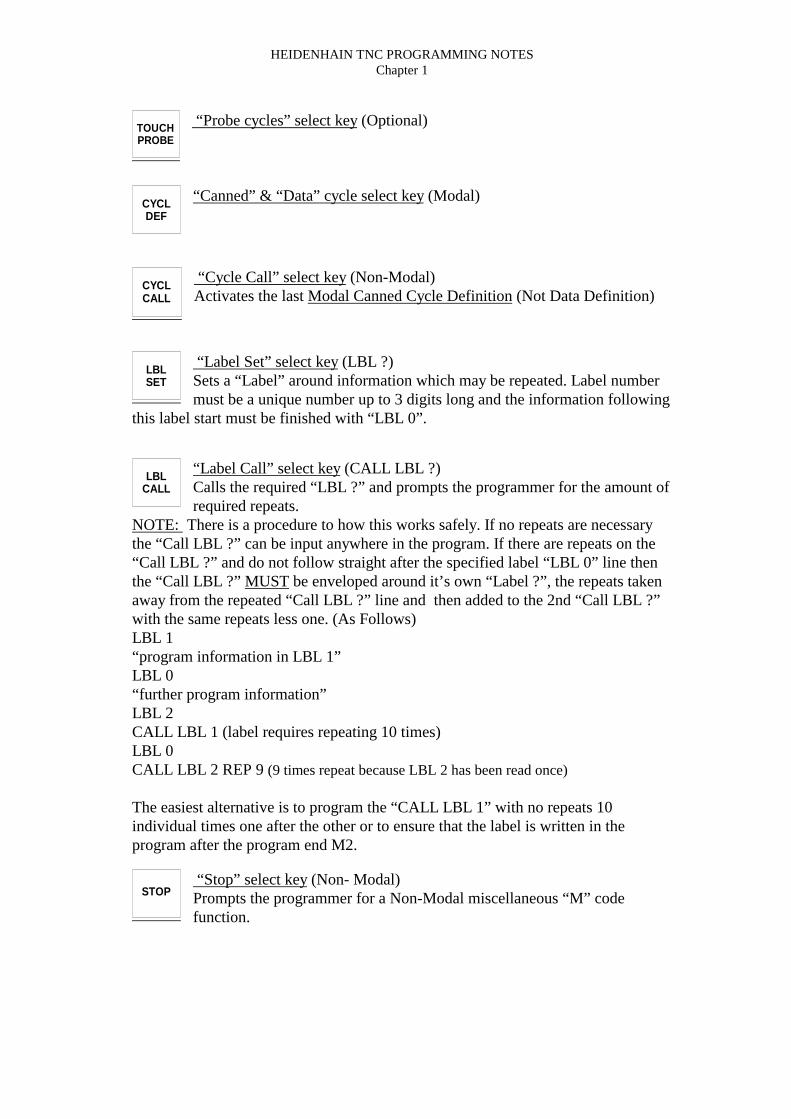
“Probe cycles” select key (Optional)
“Canned” & “Data” cycle select key (Modal)
“Cycle Call” select key (Non-Modal)Activates the last Modal Canned Cycle Definition (Not Data Definition)
“Label Set” select key (LBL ?)Sets a “Label” around information which may be repeated. Label numbermust be a unique number up to 3 digits long and the information following
this label start must be finished with “LBL 0”.
“Label Call” select key (CALL LBL ?)Calls the required “LBL ?” and prompts the programmer for the amount ofrequired repeats.
NOTE: There is a procedure to how this works safely. If no repeats are necessarythe “Call LBL ?” can be input anywhere in the program. If there are repeats on the“Call LBL ?” and do not follow straight after the specified label “LBL 0” line thenthe “Call LBL ?” MUST be enveloped around it’s own “Label ?”, the repeats takenaway from the repeated “Call LBL ?” line and then added to the 2nd “Call LBL ?”with the same repeats less one. (As Follows)LBL 1“program information in LBL 1”LBL 0“further program information”LBL 2CALL LBL 1 (label requires repeating 10 times)LBL 0CALL LBL 2 REP 9 (9 times repeat because LBL 2 has been read once)
The easiest alternative is to program the “CALL LBL 1” with no repeats 10individual times one after the other or to ensure that the label is written in theprogram after the program end M2.
“Stop” select key (Non- Modal)Prompts the programmer for a Non-Modal miscellaneous “M” codefunction.
TOUCHPROBE
CYCLDEF
CYCLCALL
LBLSET
LBLCALL
STOP

HEIDENHAIN TNC PROGRAMMING NOTESChapter 1
“Tool Definition ” select key (MODAL)If the tool library is not set by parameters the program must containinformation with regard the tool length and the “RADIUS”. If the radius is
not necessary for the program i.e. a drill then it will be required if the graphics areused.
“Tool Call” select keySelecting this key will prompt the programmer for the required tool changenumber, the spindle revolutions and the working spindle axis which would
be “Z” in X & Y axis programming.
“Alternative Program Call” select keySelecting this key will prompt the programmer for the required programnumber which exists in the program library.
“Switch Table” select keySelecting this key will switch the display back and forth between the lastscreen display and the current screen display.
“Graphic / Text Display” select keySelecting this key, and selecting one of the prompt switches below thescreen will allow the programmer to view the “Programmed Text”, “The
Graphics”,“Sections” or “Status”.
TOOLDEF
TOOLCALL
PGMCALL

HEIDENHAIN TNC PROGRAMMING NOTESChapter 1
(Other Program Keys)
Polar Key (P) NOTE: NON-MODALSelecting this key in conjunction with the other programming keys will transform theselected axis co-ordinates into “Polar” or angular co-ordinates.
Incremental Key (I) NOTE: NON-MODALSelecting this key in conjunction with the programmed axis (X, Y or Z)keys will transformthe selected axis co-ordinates into “Incremental” co-ordinates.
“X” axis select Key
“Y” axis select Key
“Z” axis select Key
“4th” axis select Key
“5th” axis select Key (TNC426 or TNC430 only)
“Clear” numerical entry key
“Delete Block” key
“Q Def.” key (Parametric Expressions or Macro Programming)
“Data Transfer” keyTransfer’s the highlighted axis information into the selected program block.
P
I
X
Y
Z
IV
V
CE
DEL
Q

HEIDENHAIN TNC PROGRAMMING NOTESChapter 1
“Data Skip” key
“End Of Block” key
“Enter Block Information” key
“Search Back” keyUsed in “Editing”, “Test Run”, “Program Run” & “MDI”.
“Search Forward” keyUsed in “Editing”, “Test Run”, “Program Run” & “MDI”.
“Search Right” keyUsed in “Editing” & “MDI”.
“Search Left” keyUsed in “Editing” & “MDI”.
“Search For Block Number” keyUsed in “Editing”, “Test Run”, “Program Run” & “MDI”. Must be used toselect the addressed block for program run.
“Program Library” select keySelect this key in program editing mode or program run mode to createnew programs or call existing programs. Only 1 directory exists in existing
Heidenhain controls except the TNC426 & TNC430 which has unlimiteddirectories. Highlighting the required program and depressing the “Enter” key willtransfer it to the appropriate menu (Run or Edit). Also data transfer and programdelete will be found here.
“Modification ” select keySelecting this key will allow the programmer or operator to change theposition display, change the data transfer parameters and also by using
special pass numbers allows the programmer to enter the main parameters table.
NOENT
END
ENT
GOTO
PGMMGT
MOD

HEIDENHAIN TNC PROGRAMMING NOTESChapter 2
11
CHAPTER 2CHAPTER 2CHAPTER 2CHAPTER 2

HEIDENHAIN TNC PROGRAMMING NOTESChapter 2
12
Process from Drawing to Product completion
1. Drawing
Examine drawing to determine fixturing,machining origin, process and tooling. .
..
.2. Program preparation
Prepare a program while considering cuttingconditions as R.P.M., depth of cuts and feedrates.
T1 M6
G0 G90 G40 G17 G94
X0 Y0 S1000 M3
3. Program creation
Write the program in the control or anotherediting source (P.C.) as per the programpreparation.
4. Test run
Test the mathematics of the program using the testrun facilities i.e. Graphics & program run. (TEST RUN)
5. Machining
Set tools, set offset values and then process a trialtest workpiece.
VMC 500
6. Product completion and Inspection

HEIDENHAIN TNC PROGRAMMING NOTESChapter 2
13
Cutting Condition Commands
Cutting conditions should be carefully examined when preparing a program, sincethese conditions greatly influence cutting efficiency and accuracy. The cutting
conditions that determine the rate of metal removal are the “Cutting Speed”, the“Feedrate”, the “Depth of Cut” & the “Width of Cut”. These cutting conditions andthe nature of the material to be cut determine the power required to take the cut. The
cutting conditions must be adjusted to stay within the power available on the machinetool to be used. These conditions also effect the tool life, which would need
consideration.
The following cutting conditions are required for all tooling used:
Spindle Speed – R.P.M. (Revolutions per Minute)Designated with an S command.
400 rpm ⇒ S400
Formula
R.P.M. = Constant Surface Speed (C.S.S.) x 1000π x Diameter
C.S.S. can be found in all manufacturers tooling guides.
Feedrate – mm/min. , inch/min. , feed/tooth, feed/rev.Designated with an F command.
400 mm/min. ⇒ F400
Formula
Feed = Number of teeth x feed/tooth (pitch) x R.P.M.
Feed/tooth can be found in all manufacturers tooling guides.

HEIDENHAIN TNC PROGRAMMING NOTESChapter 2
Table of Miscellaneous Codes (M Functions)a) There are two types of programming codes:
Non-Modal - The programmed action code is active only in the block in which it isspecified & is self-canceling.
Modal - The programmed action code remains active when programmed for everyline of program and until it is replaced by another action code of the same group type.
M Code FUNCTION ( * Option) STARTOF SPAN
END OFSPAN
M00 Program Stop •M01 Program Stop by switch •M02 End Of Program •M03 Spindle Clockwise •M04 Spindle Anti-Clockwise •M05 Spindle Stop •M06 Toolchange ••••M08 External Coolant On •M09 Coolant Off •M10 4th Axis Unclamp * •M11 4th Axis Clamp * •M13 Spindle Clockwise With External Coolant •M14 Spindle Anti-Clockwise With External Coolant •M19 Spindle Orientates To Toolchange Position •M26 Z Axis Full Retract ••••M23 Thro’ Spindle Coolant + Spindle Clockwise * •M24 Thro’ Spindle Coolant + Spindle Anti-Clockwise * •M28 Thro’ Spindle Coolant * •M30 End Of Program – Return Spindle tool to Drum ••••M89 Modal Cycle Call ••••M90 Constant Contour Speed at Corners ••••M91 Co-ordinates are referenced to machine co-ordinates •M94 Reduce rotary axis display to a value below 360 degrees •M97 Machine small contour steps •M99 Non-modal cycle call •
M103 Reduce the feedrate during plunging to factor f •M109 Constant contour feed at cutting tool edge (increase and decrease) •M110 Constant contour feed at cutting tool edge (decrease only) •M111 Reset M109/M110 •
M00 – Program Stop:After executing the block where the M00 is commanded, automatic operation stopsthe machine including the feed, spindle and coolant. Pressing the Cycle Start buttonresumes all operations.M01 – Optional Program Stop:M01 is identical to M00 but is actioned by a switch in the screen. When this switch is“ON” then the code acts as M00, but when the switch is “OFF” the code is ignoredand operation continues as programmed. Applications include: Checks on dimensions,Checks on tools and to remove chips during machining.

HEIDENHAIN TNC PROGRAMMING NOTESChapter 3
4
CHAPTER 3CHAPTER 3CHAPTER 3CHAPTER 3

HEIDENHAIN TNC PROGRAMMING NOTESChapter 3
5
“Absolute Scale”
Tool motion assumes now that the spindle moves and not the table
10 30 50 70 90-10-30-50-70-90
30
50
70
90
-10
-30
-50
-70
-90
X+X-
Y-
Y+
10
30
50
70
90
-10
-30
-50
-70
-90
Z-
Z+

HEIDENHAIN TNC PROGRAMMING NOTESChapter 3
6
“Absolute Programming”
Y
X
40
80
120
160
90
3050
80
X+X-
Y-
Y+
L X40 Y90L X80 Y30L X120 Y80L X160 Y50

HEIDENHAIN TNC PROGRAMMING NOTESChapter 3
7
“Incremental (I) Scale” Tool motion assumes now that the spindle moves and not the table
10 30 50 70 90-10-30-50-70-90
30
50
70
90
-10
-30
-50
-70
-90
X+X-
Y-
Y+
10
30
50
70
90
-10
-30
-50
-70
-90
Z-
Z+
0

HEIDENHAIN TNC PROGRAMMING NOTESChapter 3
6
Incremental (I) Programming
Y
X
40 40 40 40
6050
30
90
X+X-
Y-
Y+
L X40 Y90L IX40 IY-60L IX40 IY50L IX40 IY-30

HEIDENHAIN TNC PROGRAMMING NOTESChapter 4
CHAPTER 4

HEIDENHAIN TNC PROGRAMMING NOTESChapter 4
Cutter Compensation ApplicationClimb Milling (Radius Left - RL)
Conventional Milling (Radius Right - RR)
90° 90°
Rad
ius
Lef
t (R
L)
Rad
ius
Rig
ht (
RR
)
Rad
ius
Lef
t (R
L)
Rad
ius
Rig
ht (
RR
)
NoteAll Compensated program data is created from information contained in the “RadiusOffset” column in the “Tool” tables (if used) or, the “Radius Offset” on a Tool Def.
program line.
Using Right Hand cutters (as above)To leave material on the contour or pocket “ADD” the offset value to the value in the
Radius Offset data on the Tool Def program line or the radius column of the tooltable.
To remove material on the contour or pocket “SUBTRACT” the offset value to thevalue in the Radius Offset data on the Tool Def program line or the radius column of
the tool table.

HEIDENHAIN TNC PROGRAMMING NOTESChapter 4
Compensation types
Circle Tangent Line Tangent Line Normal
11 2 1RL R0
RL R0 RL R0
Circle Tangent LineTangent
1 RL
R0
LineNormal
1
RL R0
RLR0 1 1
RL
R0
Circle Tangent Line Tangent
Circle Tangent Line Normal
1
RL
R0
1
RL
R0
1
RL
R0
Line Normal
1
RL
R0

HEIDENHAIN TNC PROGRAMMING NOTESChapter 4
Approach Line Tangent
L X-10 Y+30 R0 FMAX M3APPR LT X+40 Y+30 LEN+15 RL F200L X+80 Y+80
APPR LT
40.00
10.00
30.00
15.00
30.00RL1
280.00
80.00

HEIDENHAIN TNC PROGRAMMING NOTESChapter 4
Approach Line Normal
L X-10 Y+30 R0 FMAX M3APPR LN X+40 Y+30 LEN+15 RL F200L X+80 Y+80
APPR LN
40.00
10.00
30.00 30.00
1
280.00
80.00
15
RL

HEIDENHAIN TNC PROGRAMMING NOTESChapter 4
Approach Circle Tangent
L X-10 Y+30 R0 FMAX M3APPR CT X+40 Y+30 CCA+90 R15 RL F200L X+80 Y+80
APPR CT
40.00
10.00
30.00 30.00
1
280.00
80.00
15
RL
90 Deg 15R
Rapid

HEIDENHAIN TNC PROGRAMMING NOTESChapter 4
Approach Line Circle Tangent
L X-10 Y+30 R0 FMAX M3APPR LCT X+40 Y+30 R15 RL F200L X+80 Y+80
APPR LCT
40.00
10.00
30.00 30.00
1
280.00
80.00
15
RL
90 Deg 15R
Feed

HEIDENHAIN TNC PROGRAMMING NOTESChapter 4
Depart Line Tangent
L Y+30 RL F100DEP LT LEN+15
DEP LT
2
3
15.00
80.00
30.00

HEIDENHAIN TNC PROGRAMMING NOTESChapter 4
Depart Line Tangent
L Y+30 RL F100DEP LN LEN+15
DEP LN
2
3
80.00
30.00
20.00

HEIDENHAIN TNC PROGRAMMING NOTESChapter 4
Depart Circle Tangent
L Y+30 RL F100DEP CT CCA+90 R+15
DEP CT
2
3
80.00
30.00
90 Deg 15R

HEIDENHAIN TNC PROGRAMMING NOTESChapter 4
Depart Line Circle Tangent
L Y+30 RL F100DEP LCT X+110 Y+30 CCA+90 R15
DEP LCT
2
3
80.00
30.00
90 Deg 15R
110.00
20.00

HEIDENHAIN TNC PROGRAMMING NOTESChapter 5
CHAPTER 5

HEIDENHAIN TNC PROGRAMMING NOTESChapter 5
Program Start:Selecting this key in the Program and Editing mode will ask the operator forthe “File Name” which can be a file name up to 8 characters. Use “SelectType” for choice of program (.H = Heidenhain, .I = ISO).
The total number of files is 64 or 128KB (410) or 1.5GB (426).The operator will then be prompted for the choice of either metric or imperialprogramming co-ordinates.At the program start the operator will be prompted with the “Blank Form Definition”or it can be searched for using the screen additional menu’s keys for the “Blank form”setting key.
Toolchange: (without tool table)
TOOL DEF? L? R? ; Tool information lineTOOL CALL? Z S? F? DL? DR? DR2? ; Toolcall lineL M6 ; Toolchange line
The Tool File can be activated by setting Parameter 7260.0 to the required numberof tool rows in a file.
The “Tool Def” program line requires no values in the LENGTH and RADIUSsections with the use of a tool table.
Tool information (Set by the programmer as required)TOOL DEF? - Tool offset numberL? - Tool Length information.R? - Tool Radius (Used for compensation & graphics).
Toolchange information (Set by the programmer as required)TOOL CALL? - Tool number - 2 Digit number (pocket)Z? - Axis the tool is aligned with.S? - Tool Spindle Speed.F? - Automatic feed selection. (Using material data base)DL? - Additional tool length offset. (Roughing purposes)DR? - Additional tool radius offset. (Roughing purposes)DR2? - Second additional tool radius offset. (426 3D tool compensation)
Text messages (Set by the programmer as required); - Program Text - 55 characters limit.
ToolchangeL - Select the “L” key and continuous “NO ENTER” until “M” is reached (Automaticload).M6 - Toolchange code.
For manual load use a tool number greater than the number of automatic toolpockets.
PGMMGT

HEIDENHAIN TNC PROGRAMMING NOTESChapter 5
Program CreationEdit Graphics
Selecting the GRAPHICS key as above will prompt the user with the following 3keys:
Selecting the PGM + GRAPHICS key as above will prompt the user with thefollowing keys:
The GRAPHIC keys are as follows:AUTO DRAW - Allows the pencil graphics to be used.
RESET + START - Will run the graphics in Full Run Mode.CLEAR GRAPHICS - Clears the graphic screen.
START SINGLE BLOCK - Runs the graphics block by block on pressing this key.SHOW/OMIT BLOCK NR. - Block number details shown on graphics.
<< >> - Graphic zoom.WINDOW DETAIL - Redraws zoom area.
START - Restarts graphics after a program stop.
Selecting the PGM + SECTS key as above will allow the programmer to TAGcertain information to a specific area of program using the INSERT SECTION key
as below.

HEIDENHAIN TNC PROGRAMMING NOTESChapter 5
(LINE Exercise PGM 10101)
80mm Square
100mm Square
Plan 20
40
Side

HEIDENHAIN TNC PROGRAMMING NOTESChapter 5
(LINE Exercise PGM 10101)
0 BEGIN PGM 10101 MM1 BLK FORM 0.1 Z X-50 Y-50 Z-402 BLK FORM 0.2 X+50 Y+50 Z+03 TOOL DEF 14 TOOL CALL 1 Z S10005 L M66 L X-70 Y-70 R0 FMAX M137 L Z-20 FMAX8 APPR ?9 L Y+4010 L X+4011 L Y-4012 L X-4013 DEP ?14 TOOL CALL 015 L M616 M3017 END PGM 10101 MM
80mm Square
100mm Square
Plan 20
40
Side

HEIDENHAIN TNC PROGRAMMING NOTESChapter 5
(LINE Exercise PGM 10102)
100mm Square
Plan
Side
20
40

HEIDENHAIN TNC PROGRAMMING NOTESChapter 5
(LINE Exercise PGM 10102)
0 BEGIN PGM 10102 MM1 BLK FORM 0.1 Z X-50 Y-50 Z-402 BLK FORM 0.2 X+50 Y+50 Z+03 TOOL DEF 14 TOOL CALL 1 Z S10005 L M66 L X-20 Y-20 R0 FMAX M137 L Z-20 FMAX8 APPR ?9 L X+0 Y+5010 L X+50 Y+011 L X-50 Y+012 L X-50 Y+013 DEP ?14 TOOL CALL 015 L M616 M3017 END PGM 10102 MM
100mm Square
Plan
Side
20
40

HEIDENHAIN TNC PROGRAMMING NOTESChapter 5
Chamfers & Blend RadiiBlend chamfers and Blend Radii can be created within a program with the aid of the CHF
& RND keys.The CHF & RND values are Non-Modal values and are inserted into the program line after
the end point has been programmed (the known intersection programmed point)
1
2
3
80 mm
CHF = chamfer length
(1 to 2) L X0 Y80CHF ? F?
(2 to 3) L X? Y0
1
2
3
80 mm
RND = Blend radiusRND
(1 to 2) L X0 Y80RND ? F?
(2 to 3) L X? Y0

HEIDENHAIN TNC PROGRAMMING NOTESChapter 5
(Chamfer Exercise PGM 10103)
100mm Square
Plan
Side40
15
15 20

HEIDENHAIN TNC PROGRAMMING NOTESChapter 5
(Chamfer Exercise PGM 10103)
0 BEGIN PGM 10103 MM1 BLK FORM 0.1 Z X-50 Y-50 Z-402 BLK FORM 0.2 X+50 Y+50 Z+03 TOOL DEF 1 L+0 R+104 TOOL CALL 1 Z S10005 L M66 L X-70 Y-20 R0 FMAX M137 L Z-20 FMAX8 APPR ?9 L X+0 Y+5010 CHF 1511 L X+50 Y+012 CHF 1513 L X+0 Y-5014 CHF 1515 L X-50 Y+016 DEP ?17 TOOL CALL 018 L M619 STOP M3020 END PGM 10103 MM
100mm Square
Plan
Side40
15
15 20

HEIDENHAIN TNC PROGRAMMING NOTESChapter 5
(Corner Rounding Exercise PGM 10104)
100mm Square
Plan
Side40
20
15 R

HEIDENHAIN TNC PROGRAMMING NOTESChapter 5
(Corner Rounding Exercise PGM 10104)
0 BEGIN PGM 10104 MM1 BLK FORM 0.1 Z X-50 Y-50 Z-402 BLK FORM 0.2 X+50 Y+50 Z+03 TOOL DEF 14 TOOL CALL 1 Z S10005 L M66 L X-70 Y-20 R0 FMAX M37 L Z-20 FMAX8 APPR ?9 L X+0 Y+5010 RND R1511 L X+50 Y+012 RND R1513 L X+0 Y-5014 RND R1515 L X-50 Y+016 DEP ?17 TOOL CALL 018 L M619 STOP M3020 END PGM 10104 MM
100mm Square
Plan
Side40
20
15 R

HEIDENHAIN TNC PROGRAMMING NOTESChapter 6
CHAPTER 6

HEIDENHAIN TNC PROGRAMMING NOTESChapter 6
(Circle Boss Exercise PGM 10105)
100mm Square
Plan
40
Side
20
35 R

HEIDENHAIN TNC PROGRAMMING NOTESChapter 6
(Circle Boss Exercise PGM 10105)
0 BEGIN PGM 10105 MM1 BLK FORM 0.1 Z X-50 Y-50 Z-402 BLK FORM 0.2 X+50 Y+50 Z+03 TOOL DEF 14 TOOL CALL 1 Z S10005 L M66 L X+70 Y+0 R0 FMAX M37 L Z-20 FMAX8 APPR ?9 CC X+0 Y+010 C X+35 Y+0 DR-11 DEP ?12 TOOL CALL 013 L M614 STOP M3015 END PGM 10105 MM
100mm Square
Plan
40
Side
20
35 R

HEIDENHAIN TNC PROGRAMMING NOTESChapter 6
(Circle Centre Arc (CC) Exercise PGM 10106)
100mm Square
Plan20
50
80
50
23.542
23.542
20
40
Side

HEIDENHAIN TNC PROGRAMMING NOTESChapter 6
(Circle Centre Arc (CC) Exercise PGM 10106)
0 BEGIN PGM 10106 MM1 BLK FORM 0.1 Z X+0 Y+0 Z-402 BLK FORM 0.2 X+100 Y+100 Z+03 TOOL DEF 14 TOOL CALL 1 Z S10005 L M66 L X-20 Y+50 R0 FMAX M37 L Z-20 FMAX8 APPR ? F? M89 L X+23.54210 CC X+50 Y+5011 C X+23.542 Y+80 DR+12 L X+013 DEP ?14 TOOL CALL 015 L M616 STOP M3017 END PGM 10106 MM
100mm Square
Plan20
50
80
50
23.542
23.542
20
40
Side

HEIDENHAIN TNC PROGRAMMING NOTESChapter 6
(Circle Arc (RAD) Exercise PGM 10107)
100mm Square
Plan20
80
23.542
23.542
20
40
Side
40 R

HEIDENHAIN TNC PROGRAMMING NOTESChapter 6
(Circle Arc (RAD) Exercise PGM 10107 text)
0 BEGIN PGM 10107 MM1 BLK FORM 0.1 Z X+0 Y+0 Z-402 BLK FORM 0.2 X+100 Y+100 Z+03 TOOL DEF 14 TOOL CALL 1 Z S10005 L M66 L X-20 Y+50 R0 FMAX M37 L Z-20 FMAX8 APPR ?9 L X+23.54210 CR X+23.542 Y+80 R-40 DR+11 L X+012 DEP ?13 TOOL CALL 014 L M615 STOP M3016 END PGM 10107 MM
100mm Square
Plan20
80
23.542
23.542
20
40
Side
40 R
HEIDENHAIN TNC PROGRAMMING NOTESChapter 6
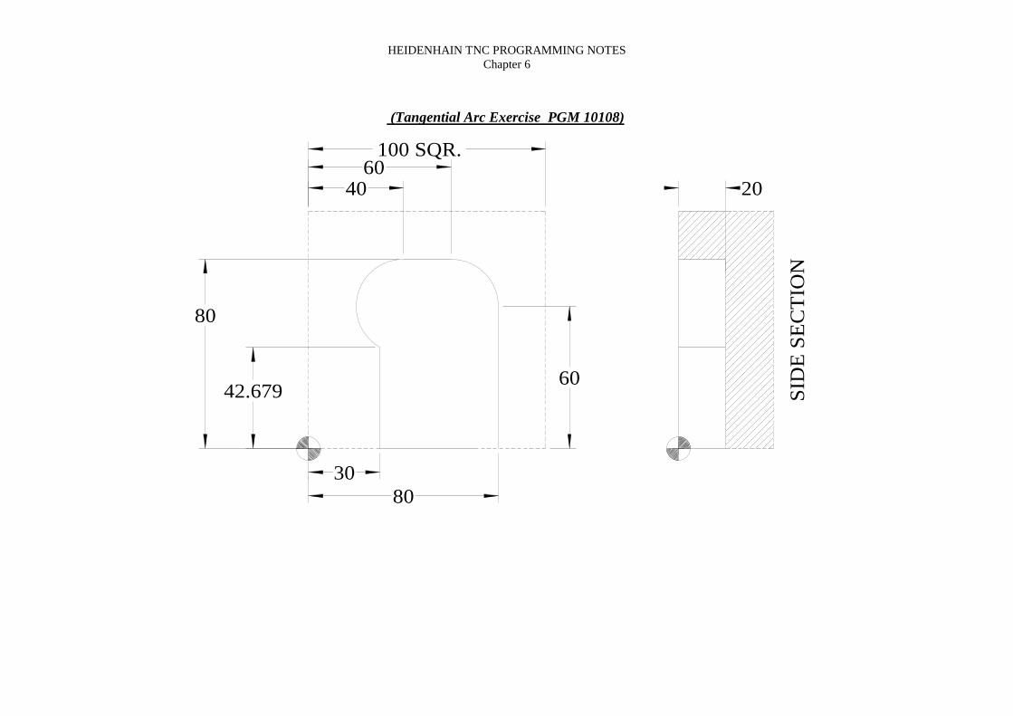
(Tangential Arc Exercise PGM 10108)
100 SQR.
SID
E S
EC
TIO
N
3080
60
42.679
80
60
2040

HEIDENHAIN TNC PROGRAMMING NOTESChapter 6
(Tangential Arc Exercise PGM 10108 text)
100 SQR.
SID
E S
EC
TIO
N
3080
60
42.679
80
60
2040
0 BEGIN PGM 10108 MM1 BLK FORM 0.1 Z X+0 Y+0 Z-402 BLK FORM 0.2 X+100 Y+100 Z+03 TOOL DEF 14 TOOL CALL 1 Z S10005 L M66 L X+60 Y-20 R0 FMAX M37 L Z-20 FMAX8 APPR ? F? M89 L Y+6010 CT X+60 Y+8011 L X+4012 CT X+30 Y+42.67913 L Y+014 DEP ?15 TOOL CALL 016 L M617 L M3018 END PGM 10108 MM

HEIDENHAIN TNC PROGRAMMING NOTESChapter 6
(Circular Arc Exercise PGM 10109)
100 SQR.
15
85
50
20
100 R

HEIDENHAIN TNC PROGRAMMING NOTESChapter 6
(Circular Arc Exercise PGM 10109)
100 SQR.
15
85
50
20
100 R
0 BEGIN PGM 10109 MM1 BLK FORM 0.1 Z X+0 Y+0 Z-402 BLK FORM 0.2 X+100 Y+100 Z+03 TOOL DEF 14 TOOL CALL 1 Z S10005 L M66 L X-20 Y-20 R0 FMAX M37 L Z-20 FMAX8 APPR?9 L Y+5010 CR X+85 Y+50 R+100 DR-11 L Y+012 DEP?13 TOOL CALL 014 L M615 L M3016 END PGM 10109 MM

HEIDENHAIN TNC PROGRAMMING NOTESChapter 6
(Circular Arc Exercise PGM 10110)
100
100
60
51.927
16.026
29.373
60.562
34.435
20.9
95
29.9
98
68.309
70
20 R
10 R
80 R
75 R

HEIDENHAIN TNC PROGRAMMING NOTESChapter 6
(Circular Arc Exercise PGM 10110 text)
0 BEGIN PGM 10110 MM1 BLK FORM 0.1 Z X+0 Y+0 Z-402 BLK FORM 0.2 X+100 Y+100 Z+03 TOOL DEF 14 TOOL CALL 1 Z S10005 L M66 L X+60 Y+120 R0 FMAX M37 L Z-20 FMAX8 APPR?9 CR X+60.562 Y+29.998 R+20 DR-10 CR X+29.373 Y+20.995 R+75 DR+11 CR X+16.026 Y+34.435 R+10 DR-12 CR X+51.927 Y+68.309 R+80 DR-13 CR X+60 Y+70 R+20 DR-14 DEP?15 TOOL CALL 016 L M617 L M3018 END PGM 10110 MM
100
100
60
51.927
16.026
29.373
60.562
34.43520
.995
29.9
9868.309
70
20 R
10 R
80 R
75 R

HEIDENHAIN TNC PROGRAMMING NOTESChapter 7
CHAPTER 7

HEIDENHAIN TNC PROGRAMMING NOTESChapter 7
44
Working Planes
XY Plane (Z)
Plan View Front View Side View
XZ Plane (Y) YZ Plane (X)
0
0
0
90-270
180-180
270-90
+
+
+
-
- -
DR-DR+
90-270
90-270
270-90
270-90
180-180
180-180

HEIDENHAIN TNC PROGRAMMING NOTESChapter 7
45
Polar Co-ordinate Command
The control has the ability to position itself to an endpoint in any plane using a “P”code with an “L” code giving only the information regarding the radius of the movefrom the PCD centre point with the angle of the line as that of a right angled triangle.
All angles are relative to the current plane.
LP PR? PA? R? F? M?
Where:LP = PCD Polar command – Line Polar
PR? = Radius of the PCD actionPA? = Angle of the move
R? = Radius compensationF? = Feedrate
It is possible to use incremental to control the angle.If the X & Y positions in the “CC” line of program to the PCD centre are omitted,
then the current tool position will become the pole PCD centre.
PA
PRRequired XY position
CC X?
CC Y?

HEIDENHAIN TNC PROGRAMMING NOTESChapter 7
46
(Linear Polar Exercise PGM 10111)
30
40
8090
30
27
5
640
20
100 SQR.

HEIDENHAIN TNC PROGRAMMING NOTESChapter 7
47
(Linear Polar Exercise PGM 10111)
30
40
8090
30
27
5
640
20
100 SQR.
0 BEGIN PGM 10111 MM1 BLK FORM 0.1 Z X+0 Y+0 Z-402 BLK FORM 0.2 X+100 Y+100 Z+03 TOOL DEF 14 TOOL CALL 1 Z S5005 L M66 L X-20 Y+0 R0 FMAX M37 L Z-20 FMAX8 L APPR ?9 L Y+4010 CC11 LP PR+30 PA+6012 CC13 LP PR+40 IPA-2714 CC15 LP PR+80 IPA-9016 L X+5 Y+617 DEP ?18 L Z100 FMAX19 TOOL CALL 020 L M621 L M222 END PGM 10110 MM

HEIDENHAIN TNC PROGRAMMING NOTESChapter 7
48
(Hexagon PGM 10111)
100 SQR.
R40
60 Deg.
20

HEIDENHAIN TNC PROGRAMMING NOTESChapter 7
49
(Hexagon PGM 10112)
100 SQR.
R40
60 Deg.
20
0 BEGIN PGM 10112 MM1 BLK FORM 0.1 Z X+0 Y+0 Z-402 BLK FORM 0.2 X+100 Y+100 Z+03 TOOL DEF 14 TOOL CALL 1 Z S10005 L M66 L X-20 Y-20 R0 FMAX M37 L Z-20 FMAX8 APPR ?9 CC X+50 Y+5010 LP PR+40 PA+18011 LP PA+12012 LP PA+6013 LP PA+014 LP PA-6015 LP PA-12016 LP PA-18017 L Y+12018 DEP ?19 TOOL CALL 020 L M621 L M3022 END PGM 10111 MM

HEIDENHAIN TNC PROGRAMMING NOTESChapter 7
50
Circular Polar Co-ordinate Command
The control has the ability to position itself to an endpoint in any plane using a “P”code with a “`C” code giving only the information regarding the angle that the circle
stops at relative to zero degrees and around a specified Circle Centre position.All angles are relative to the current plane.
CP PA? D? R? F? M?
Where:CP = Circular Polar command
PA? = Stopping angle of the moveD? = Direction of circular move
R? = Radius compensationF? = Feedrate
It is possible to use incremental to control the angle.Using CP IPA? would control the angle from the starting position.
PA
Required XY position
CC X?
CC Y?
Start Point
PR

HEIDENHAIN TNC PROGRAMMING NOTESChapter 7
51
(Circle Boss Exercise (polar) PGM 10114)
100 SQR.
SIDE
20
35 R

HEIDENHAIN TNC PROGRAMMING NOTESChapter 7
52
(Circle Boss Exercise (polar) PGM 10114)
100 SQR.
SIDE
20
35 R
0 BEGIN PGM 10114 MM1 BLK FORM 0.1 Z X-50 Y-50 Z-402 BLK FORM 0.2 X+50 Y+50 Z+03 TOOL DEF 14 TOOL CALL 1 Z S10005 L M66 L X+70 Y+0 R0 FMAX M37 L Z-20 FMAX8 APPR ?9 CC X+50 Y+5010 CP IPA+360 DR- (or CP PA+0 DR-)11 DEP ?12 TOOL CALL 013 L M614 L M3014 END PGM 10114 MM
HEIDENHAIN TNC PROGRAMMING NOTESChapter 7
53
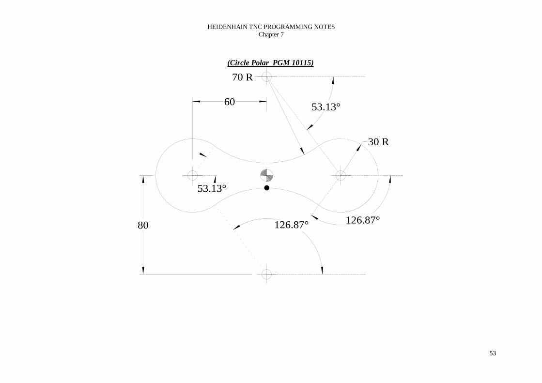
(Circle Polar PGM 10115)
60 53.13°
126.87°
53.13°
126.87°
30 R
70 R
80

HEIDENHAIN TNC PROGRAMMING NOTESChapter 7
54
(Circle Boss Exercise (polar) PGM 10115)
60 53.13°
126.87°
53.13°
126.87°
30 R
70 R
80
0 BEGIN PGM 10115 MM1 BLK FORM 0.1 Z X-90 Y-15 Z-402 BLK FORM 0.2 X+90 Y+15 Z+03 TOOL DEF 14 TOOL CALL 1 Z S10005 L M66 L X+0 Y-20 R0 FMAX M37 L Z-20 FMAX8 APPR ?9 CC X+0 Y-8010 CP PA+126.87 DR+11 CC X-60 Y+012 CP PA+53.13 DR-13 CC X+0 Y+8014 CP PA-53.13 DR+15 CC X+60 Y+016 CP PA-126.87 DR-17 CC X+0 Y-8018 CP PA+90 DR+19 DEP ?20 TOOL CALL 021 L M622 L M3023 END PGM 10115 MM

HEIDENHAIN TNC PROGRAMMING NOTESChapter 8
CHAPTER 8

HEIDENHAIN TNC PROGRAMMING NOTESChapter 8
Drilling cycles
The TNC offers machining cycles for all types of holeoperations.
Cycle Softkey
1 - Pecking without automatic pre-positioning.
200 - Drilling with automatic pre-positioning and2nd setup clearance.
201 - Reaming with automatic pre-positioning and2nd setup clearance.
202 - Boring with automatic pre-positioning and2nd setup clearance.
203 - Universal Drilling with automatic pre-positioning,2nd setup clearance, chip breaking and decrement.
204 - Back Boring with automatic pre-positioning and2nd setup clearance.
2 - Tapping with a floating tap holder.
17 - Rigid Tapping without a floating holder.
18 - Thread Cutting (426).
209 – Tapping with chip breaking.
1
200
201
202
203
204
2
17
18
209

HEIDENHAIN TNC PROGRAMMING NOTESChapter 8
Pecking (Cycle 1)1) The tool drills from the “Current Position” to the first PECKING DEPTH at theprogrammed FEED RATE F.2) When it reaches the first pecking depth, the tool retracts in rapid traverse FMAXto the starting position and advances again to the first PECKING DEPTH minusthe advanced stop distance t.3) The advance stop distance is automatically calculated by the control: At a total hole depth of up to 30mm :t = 0.6mm At a total hole depth exceeding 30mm :t = hole depth / 50.Maximum advanced stop distance = 7mm.4) The tool then advances with another infeed at the programmed FEED RATE F.5) The TNC repeats this process (1 - 4) until the programmed TOTAL HOLEDEPTH is reached.6) After a DWELL TIME at the bottom of the hole, the tool is returned to thestarting position in rapid traverse FMAX for chip breaking.
NOTE: Program a positioning block for the starting point (hole center) in theworking plane with RADIUS COMPENSATION RO.
Program a positioning block for the starting point in the tool axis (SET-UPCLEARANCE above the workpiece surface).
The sign (+ or -) for the cycle parameter TOTAL HOLE DEPTH determines theworking direction.
⇒ SETUP CLEARANCE - (Incremental) Distance between tool tip (at startposition) and workpiece surface.
⇒ TOTAL HOLE DEPTH - (Incremental) Distance between workpiece surfaceand bottom of the hole (tool tip).
⇒ PECKING DEPTH - (Incremental) Infeed per cut. The tool will drill to theDEPTH in one movement if :a) the PECKING DEPTH equals the TOTALHOLE DEPTH. b) the PECKING DEPTH is greater than the TOTAL HOLEDEPTH.
⇒ DWELL TIME IN SECONDS - Amount of time the tool remains at the totalhole depth for chip breaking.
⇒ FEED RATE F - Traversing speed of the tool during drilling.

HEIDENHAIN TNC PROGRAMMING NOTESChapter 8
Drilling (Cycle 200)1) The TNC positions the tool in the tool axis at rapid traverse FMAX to the SET-UP CLEARANCE above the WORKPIECE SURFACE COORDINATE.2) The tool drills to the first PLUNGING DEPTH at the programmed FEEDRATE F.3) The tool is retracted to SET-UP CLEARANCE in FMAX, remains there - ifprogrammed - for the entered dwell time, and advances again in FMAX to 0.2mmabove the first PLUNGING DEPTH.4) The tool then drills deeper by the PLUNGING DEPTH at the programmedFEED RATE F.5) The TNC repeats this process (2 - 4) until the programmed TOTAL HOLEDEPTH is reached.6) At the hole bottom, the tool is retracted to SET-UP CLEARANCE or - ifprogrammed - to the 2ND SET-UP CLEARANCE in rapid traverse FMAX.
NOTE: Program a positioning block for the starting point (hole center) in theworking plane with RADIUS COMPENSATION RO.
The sign (+ or -) for the cycle parameter DEPTH determines the working direction.
⇒ SETUP CLEARANCE Q200 - (Incremental) Distance between tool tip (atstart position) and workpiece surface.
⇒ DEPTH Q201 - (Incremental) Distance between workpiece surface and bottomof the hole (tool tip).
⇒ FEED RATE FOR PLUNGING Q206 - Traversing speed of the tool duringdrilling.
⇒ PLUNGING DEPTH Q202 - (Incremental) Infeed per cut. The tool will drill tothe DEPTH in one movement if :a) the PECKING DEPTH equals the TOTALHOLE DEPTH. b) the PECKING DEPTH is greater than the TOTAL HOLEDEPTH.
⇒ DWELL TIME AT TOP Q210 - Amount of time the tool remains at the SET-UP CLEARANCE after having been retracted from the hole for chip release.
⇒ WORKPIECE SURFACE COORDINATE Q203 - (Absolute) Co-ordinate ofworkpiece surface.
⇒ 2ND SET-UP CLEARANCE Q204 - (Incremental) Co-ordinate in the toolaxis at which no collision between tool and workpiece (clamping devices) canoccur.

HEIDENHAIN TNC PROGRAMMING NOTESChapter 8
Reaming (Cycle 201)1) The TNC positions the tool in the tool axis at rapid traverse FMAX to the SET-UP CLEARANCE above the WORKPIECE SURFACE COORDINATE.2) The tool reams to the entered DEPTH at the programmed FEED RATE F.3) If programmed, the tool remains at the hole bottom for the entered dwell time.4) The tool then retracts to SET-UP CLEARANCE at the FEED RATE F , andfrom there - if programmed - to the 2ND SET-UP CLEARANCE in FMAX.
NOTE: Program a positioning block for the starting point (hole center) in theworking plane with RADIUS COMPENSATION RO.
The sign (+ or -) for the cycle parameter DEPTH determines the working direction.
⇒ SETUP CLEARANCE Q200 - (Incremental) Distance between tool tip (atstart position) and workpiece surface.
⇒ DEPTH Q201 - (Incremental) Distance between workpiece surface and bottomof the hole (tool tip).
⇒ FEED RATE FOR PLUNGING Q206 - Traversing speed of the tool duringdrilling.
⇒ DWELL TIME AT DEPTH Q211 - Amount of time the tool remains at theDEPTH.
⇒ RETRACTION FEEDRATE Q208 - Traversing feedrate of tool whenretracting from the hole. If zero is entered the tool retracts at the reaming FEEDRATE FOR PLUNGING.
⇒ WORKPIECE SURFACE COORDINATE Q203 - (Absolute) Co-ordinate ofworkpiece surface.
⇒ 2ND SET-UP CLEARANCE Q204 - (Incremental) Co-ordinate in the toolaxis at which no collision between tool and workpiece (clamping devices) canoccur.

HEIDENHAIN TNC PROGRAMMING NOTESChapter 8
Boring (Cycle 202)1) The TNC positions the tool in the tool axis at rapid traverse FMAX to the SET-UP CLEARANCE above the WORKPIECE SURFACE COORDINATE.2) The tool bores to the entered DEPTH at the programmed FEED RATE F.3) If programmed, the tool remains at the hole bottom for the entered dwell time.4) The TNC then orientates the spindle to the zero degree position with anorientated stop.5) If retraction is selected, the tool retracts in the programmed direction by 0.2mm(fixed value).6) The tool then retracts to SET-UP CLEARANCE at the RETRACTION FEEDRATE , and from there - if programmed - to the 2ND SET-UP CLEARANCE inFMAX.
NOTE: Program a positioning block for the starting point (hole center) in theworking plane with RADIUS COMPENSATION RO.
The sign (+ or -) for the cycle parameter DEPTH determines the working direction.
⇒ SETUP CLEARANCE Q200 - (Incremental) Distance between tool tip (atstart position) and workpiece surface.
⇒ DEPTH Q201 - (Incremental) Distance between workpiece surface and bottomof the hole (tool tip).
⇒ FEED RATE FOR PLUNGING Q206 - Traversing speed of the tool duringdrilling.
⇒ DWELL TIME AT DEPTH Q211 - Amount of time the tool remains at theDEPTH.
⇒ RETRACTION FEEDRATE Q208 - Traversing feedrate of tool whenretracting from the hole. If zero is entered the tool retracts at the reaming FEEDRATE FOR PLUNGING.
⇒ WORKPIECE SURFACE COORDINATE Q203 - (Absolute) Co-ordinate ofworkpiece surface.
⇒ 2ND SET-UP CLEARANCE Q204 - (Incremental) Co-ordinate in the toolaxis at which no collision between tool and workpiece (clamping devices) canoccur.
⇒ DISENGAGING DIRECTION Q214 - Direction to clear bore.0 = Do not retract the tool1 = Retract the tool in the negative main axis direction.2 = Retract the tool in the negative secondary axis direction.3 = Retract the tool in the positive main axis direction.4 = Retract the tool in the positive secondary axis direction.
NOTE: Check the position of the tool tip when you program a spindle orientation tozero degrees. Align the tool tip so that it is parallel to a coordinate axis. Select aDISENGAGING DIRECTION in which the tool moves away from the edge of thehole.

HEIDENHAIN TNC PROGRAMMING NOTESChapter 8
Universal Drilling (Cycle 203)1) The TNC positions the tool in the tool axis at rapid traverse FMAX to the SET-UPCLEARANCE above the WORKPIECE SURFACE COORDINATE.2) The tool drills to the first PLUNGING DEPTH at the programmed FEED RATE.3) If you have programmed chip breaking, the tool then retracts by 0.2mm. If you areworking without chip breaking, the tool retracts at the RETRACTION FEED RATEto SET-UP CLEARANCE, remains there - if programmed - for the entered dwelltime, and advances again in FMAX to 0.2mm above the first PLUNGING DEPTH.4) The tool then advances with another peck at the programmed FEED RATE F. Ifprogrammed, the PLUNGING DEPTH is decreased after each peck by theDECREMENT.5) The TNC repeats this process (2 - 4) until the programmed TOTAL HOLE DEPTHis reached.6) The tool remains at the hole bottom - if programmed - for the entered DWELLTIME to cut free, and then retracts to the SET-UP CLEARANCE at theRETRACTION FEED RATE. If you have entered a 2ND SET-UP CLEARANCE,the tool subsequently moves to that position in FMAX.
NOTE: Program a positioning block for the starting point (hole center) in the workingplane with RADIUS COMPENSATION RO.The sign (+ or -) for the cycle parameter DEPTH determines the working direction.
⇒ SETUP CLEARANCE Q200 - (Incremental) Distance between tool tip (at startposition) and work piece surface.
⇒ DEPTH Q201 - (Incremental) Distance between work piece surface and bottom ofthe hole (tool tip).
⇒ FEED RATE FOR PLUNGING Q206 - Traversing speed of the tool duringdrilling.
⇒ PLUNGING DEPTH Q202 - (Incremental) Peck depth. The tool will drill to theDEPTH in one movement if :a) the PECKING DEPTH equals the TOTAL HOLEDEPTH. b) the PECKING DEPTH is greater than the TOTAL HOLE DEPTH.
⇒ DWELL TIME AT TOP Q210 - Amount of time the tool remains at the SET-UPCLEARANCE after having been retracted from the hole for chip release.
⇒ WORKPIECE SURFACE COORDINATE Q203 - (Absolute) Coordinate ofwork piece surface.
⇒ 2ND SET-UP CLEARANCE Q204 - (Incremental) Coordinate in the tool axis atwhich no collision between tool and work piece (clamping devices) can occur.
⇒ DECREMENT Q212 (Increment) - Value by which the TNC decreases thePLUNGING DEPTH after each peck.
⇒ NR OF BREAKS BEFORE RETRACTING Q213 - Number of chip breaks afterwhich the TNC is to withdraw the tool from the hole for chip release. For chipbreaking, the TNC retracts the tool each time by 0.2mm.
⇒ MINIMUM PLUNGING DEPTH Q208 (Incremental) - If a decrement wasentered, this limits the final plunging depth to this value.
⇒ DWELL TIME AT DEPTH Q211 - Amount of time the tool remains at theDEPTH.
⇒ RETRACTION FEEDRATE Q208 - Traversing feed rate of tool when retractingfrom the hole. If zero is entered the tool retracts at FMAX.

HEIDENHAIN TNC PROGRAMMING NOTESChapter 8
Back Boring (Cycle 204)1) The TNC positions the tool in the tool axis at rapid traverse FMAX to the SET-UP CLEARANCE above the WORKPIECE SURFACE COORDINATE.2) The TNC then orientates the spindle to the zero degree position with an
orientated spindle stop, and displaces the tool by the OFF CENTERDISTANCE.
3) The tool is then plunged into the already bored hole at the FEED RATE FORPRE-POSITIONING until the tooth has reached SET-UP CLEARANCE onthe underside of the work piece.
4) The TNC then centers the tool again over the bore hole, switches on the spindleand the coolant and moves at the FEED RATE FOR BORING to the DEPTHof bore.
5) If a DWELL TIME is entered, the tool will pause at the top of the bore hole andwill then be retracted from the hole again. The TNC carries out anotherorientated spindle stop and the tool is once again displaced by the OFFCENTER DISTANCE.
6) The TNC moves the tool at the FEED RATE FOR PRE-POSITIONING to theSET-UP CLEARANCE and then, if entered, to the 2ND SET-UPCLEARANCE with FMAX
NOTE: Program a positioning block for the starting point (hole center) in theworking plane with RADIUS COMPENSATION RO.The sign (+ or -) for the cycle parameter DEPTH determines the working direction.The entered tool length is the total length to the underside of the boring bar and notjust to the tooth.
⇒ SETUP CLEARANCE Q200 - (Incremental) Distance between tool tip (atstart position) and work piece surface.
⇒ DEPTH Q249 - (Incremental) Depth of counter-bore from underside of workpiece.
⇒ MATERIAL THICKNESS Q250 - (Incremental)⇒ OFF-CENTER DISTANCE Q251 - (Incremental) Off center shift distance.⇒ TOOL EDGE HEIGHT Q252 - (Incremental) Tool nose thickness.⇒ FEED RATE FOR PRE-POSITIONING Q253 - Feed for moving in and out
of bore (mm/min.).⇒ FEED RATE FOR COUNTERBORING Q254 - Traversing speed of the tool
during counter boring (mm/min.).⇒ DWELL TIME Q255 - Dwell time at counter bore finish depth.⇒ WORKPIECE SURFACE COORDINATE Q203 - (Absolute) Coordinate of
work piece surface.⇒ 2ND SET-UP CLEARANCE Q204 - (Incremental) Coordinate in the tool axis
at which no collision between tool and work piece (clamping devices) can occur.⇒ DISENGAGING DIRECTION Q214 - Direction to clear bore.0 = Do not retract the tool1 = Retract the tool in the negative main axis direction.2 = Retract the tool in the negative secondary axis direction.3 = Retract the tool in the positive main axis direction.4 = Retract the tool in the positive secondary axis direction.

HEIDENHAIN TNC PROGRAMMING NOTESChapter 8
Tapping (Cycle 2)1) The thread is cut in one pass.2) Once the tool has reached the TOTAL DEPTH, the direction of spindle rotation isreversed and the tool is retracted to the starting position at the end of the DWELLTIME.3) At the starting position, the direction of spindle rotation reverses once again.
NOTE: Program a positioning block for the starting point (hole center) in theworking plane with RADIUS COMPENSATION RO.
Program a positioning block for the starting point in the tool axis (SET-UPCLEARANCE above the work piece surface).
The sign (+ or -) for the cycle parameter DEPTH determines the working direction.
A floating tap holder is required for tapping. It must compensate the tolerancesbetween feed rate and spindle speed during tapping process.
When in cycle, the spindle speed override is disabled.
For tapping right hand threads activate the spindle with M3, for left hand threads useM4.
⇒ SETUP CLEARANCE - (Incremental) Distance between tool tip (at startposition) and work piece surface. Standard value = 4 times the thread pitch.
⇒ TOTAL HOLE DEPTH - (Incremental) Distance between work piece surfaceand bottom of the hole (tool tip).
⇒ DWELL TIME IN SECONDS - Enter a value between 0 and 0.5 seconds toavoid wedging of the tool during retraction.
⇒ FEED RATE F - Traversing speed of the tool during tapping.
The feed rate is calculated as follows: F = S x PWhere:F is the feed rate.S is the spindle speed in RPM.P is the thread pitch.

HEIDENHAIN TNC PROGRAMMING NOTESChapter 8
Rigid Tapping (Cycle 17)1) The thread is cut in one pass.2) Once the tool has reached the TOTAL DEPTH, the direction of spindle rotation isreversed and the tool is retracted to the starting position at the end of the DWELLTIME.3) At the starting position, the direction of spindle rotation reverses once again.
NOTE: Program a positioning block for the starting point (hole center) in theworking plane with RADIUS COMPENSATION RO.
Program a positioning block for the starting point in the tool axis (SET-UPCLEARANCE above the workpiece surface).
The sign (+ or -) for the cycle parameter DEPTH determines the working direction.
A floating tap holder is required for tapping. It must compensate the tolerancesbetween feedrate and spindle speed during tapping process.
When in cycle, the spindle speed override is disabled.
For tapping right hand threads activate the spindle with M3, for left hand threads useM4.
The TNC calculates the feedrate from the spindle speed and the entered pitch. If thefeed override is adjusted during tapping, the feedrate will be adjusted automaticallyto suit.
⇒ SETUP CLEARANCE - (Incremental) Distance between tool tip (at startposition) and workpiece surface. Standard value = 4 times the thread pitch.
⇒ TOTAL HOLE DEPTH - (Incremental) Distance between workpiece surfaceand bottom of the hole (tool tip).
⇒ PITCH - Thread pitch. Algebraic sign differentiates between right hand and lefthand threads.
+ = Right hand thread,- = Left hand threads.

HEIDENHAIN TNC PROGRAMMING NOTESChapter 8
Thread Cutting (Cycle 18)Cycle 18 THREAD CUTTING is performed by means of spindle control. The toolmoves with the active spindle speed from its current position to the entered DEPTH.As soon as it reaches the end of thread, spindle rotation is stopped. Tool approach tothe hole surface and departure from the hole bottom must be programmedseparately.
NOTE: The TNC automatically activates and deactivates spindle rotation.Do not program M3 or M4 before the cycle call.
When in cycle, the feed rate override is disabled.
The TNC calculates the feedrate from the spindle speed and the entered pitch. If thespindle speed override is adjusted during threading, the feedrate will be adjustedautomatically to suit.
⇒ TOTAL HOLE DEPTH - (Incremental) Distance between current toolposition and the end of the thread.
⇒ PITCH - Thread pitch. Algebraic sign differentiates between right hand and lefthand threads.
+ = Right hand thread (M3 with negative depth)- = Left hand threads (M4 with negative depth)

HEIDENHAIN TNC PROGRAMMING NOTESChapter 8
Tapping with chip breaking (Cycle 209)1) The TNC positions the tool in the tool axis at rapid traverse FMAX to the SET-UP CLEARANCE above the WORKPIECE SURFACE COORDINATE. Thereit carries out an orientated spindle stop.2) The tool moves to the programmed infeed depth, reverses the direction of thespindle rotation and retracts by a specific distance or completely for chip release,dependant on the definition.3) It then reverses the direction of spindle rotation again and advances to the next infeed depth.4) The TNC repeats this process (2 – 3) until the programmed thread depth isreached.5) The tool is then retracted to SET-UP CLEARANCE, and if programmed, to the2ND CLEARANCE with FMAX.6) The TNC stops the spindle turning at SET-UP CLEARANCE
NOTE: Program a positioning block for the starting point (hole center) in theworking plane with RADIUS COMPENSATION RO.
The sign (+ or -) for the cycle parameter THREAD DEPTH determines the workingdirection.
At the end of the cycle the spindle comes to a stop. Before the next operation, restartthe spindle with M3 (or M4).
⇒ SETUP CLEARANCE Q200 - (Incremental) Distance between tool tip (atstart position) and work piece surface.
⇒ DEPTH Q201 - (Incremental) Distance between work piece surface and bottomof the hole (tool tip).
⇒ THREAD PITCH Q239 – Pitch of the thread (+ = RH, - = LH)⇒ WORKPIECE SURFACE COORDINATE Q203 - (Absolute) Co-ordinate of
work piece surface.⇒ 2ND SET-UP CLEARANCE Q204 - (Incremental) Co-ordinate in the tool
axis at which no collision between tool and work piece (clamping devices) canoccur.
⇒ DEPTH FOR CHIP BRKNG Q257 - (Incremental) In feed per cut. The toolwill tap to the DEPTH in one movement if a) the PECKING DEPTH equals theTOTAL HOLE DEPTH. b) the PECKING DEPTH is greater than the TOTALHOLE DEPTH.
⇒ DIST FOR CHIP BRKNG Q256 – Retraction rate for chip breaking. The TNCmultiplies the pitch by this value to retract the tap by this new amount before thenext peck. If Q256 = 0 then the TNC retracts the tool fully for chip breakage.
⇒ ANGLE OF SPINDLE Q336 – (Absolute) Angle at which the TNC positionsthe tool before machining the thread.
** If the program is interrupted during cycle, the TNC will display the soft key“MANUAL OPERATION”. By pressing this key, retraction of the tool ispossible. Simply press the positive axis direction button of the active tool
axis.**

HEIDENHAIN TNC PROGRAMMING NOTESChapter 8
(Drilling Cycle Exercises PGM 10116)
20
3550
20
50
80
100
20
20
50
8mm Holes

HEIDENHAIN TNC PROGRAMMING NOTESChapter 8
(Drilling Cycle PGM 10116)
20
3550
20
50
80
100
20
20
50
8mm Holes0 BEGIN PGM 10116 MM1 BLK FORM 0.1 Z X+0 Y+0 Z-202 BLK FORM 0.2 X+100 Y+50 Z+203 TOOL DEF 14 TOOL CALL 1 Z S10005 L M66 CYCL DEF 1.0 PECKING7 CYCL DEF 1.1 SET UP 58 CYCL DEF 1.2 PLNGNG -209 CYCL DEF 1.3 DWELL 010 CYCL DEF 1.4 F???11 L X+20 Y+20 R0 FMAX M312 L Z+5 FMAX13 CYCL CALL M814 L Z+25 FMAX15 L X+80 FMAX16 L Z+5 FMAX17 CYCL CALL18 L Z+25 FMAX19 CYCL DEF 1.0 PECKING20 CYCL DEF 1.1 SET UP 521 CYCL DEF 1.2 PLNGNG -4022 CYCL DEF 1.3 DWELL 023 CYCL DEF 1.4 F???24 L X+50 Y+35 FMAX25 CYCL CALL26 TOOL CALL 027 L M628 L M3029 END PGM 10116 MM

HEIDENHAIN TNC PROGRAMMING NOTESChapter 8
(Drilling Cycle Exercises PGM 10116B)
20
3550
20
50
80
100
20
20
50
8mm Holes

HEIDENHAIN TNC PROGRAMMING NOTESChapter 8
(Drilling Cycle PGM 10116B)
20
3550
20
50
80
100
20
20
50
8mm Holes0 BEGIN PGM 10116B MM1 BLK FORM 0.1 Z X+0 Y+0 Z-202 BLK FORM 0.2 X+100 Y+50 Z+203 TOOL DEF 14 TOOL CALL 1 Z S10005 L M66 CYCL DEF 200 DRILLING
Q200 = 5 ;SET-UP CLEARANCEQ201 = -20 ;DEPTHQ206 = ??? ;FEED RATE FOR PLNGNGQ202 = 5 ;PLNGNG DEPTHQ210 = 0 ;DWELL TIME AT TOPQ203 = 0 ;SURFACE COORDINATEQ204 = 25 ;2ND SET-UP CLEARANCE
7 L X+20 Y+20 R0 FMAX M38 CYCL CALL M89 L X+80 FMAX10 CYCL CALL11 CYCL DEF 200 DRILLING
Q200 = 5 ;SET-UP CLEARANCEQ201 = -40 ;DEPTHQ206 = ??? ;FEED RATE FOR PLNGNGQ202 = 5 ;PLNGNG DEPTHQ210 = 0 ;DWELL TIME AT TOPQ203 = 20 ;SURFACE COORDINATEQ204 = 5 ;2ND SET-UP CLEARANCE
12 L X+50 Y+35 FMAX13 CYCL CALL14 TOOL CALL 015 L M616 L M3017 END PGM 10116B MM

HEIDENHAIN TNC PROGRAMMING NOTESChapter 8
(Tapping Cycle PGM 10116C)
20
3550
20
50
80
100
20
20
Centre hole tap 20mm deepOther holes 10mm deep
M10 x 1.5 Tap

HEIDENHAIN TNC PROGRAMMING NOTESChapter 8
(Tapping Cycle PGM 10116C)
20
3550
20
50
80
100
20
20
Centre hole tap 20mm deepOther holes 10mm deep
M10 x 1.5 Tap
0 BEGIN PGM 10116C MM1 BLK FORM 0.1 Z X+0 Y+0 Z-202 BLK FORM 0.2 X+100 Y+50 Z+203 TOOL DEF 24 TOOL CALL 2 Z S1005 L M66 CYCL DEF 2.0 TAPPING7 CYCL DEF 2.1 SET UP 58 CYCL DEF 2.2 DEPTH -109 CYCL DEF 2.3 DWELL 010 CYCL DEF 2.4 F?11 L X+20 Y+20 R0 FMAX M312 L Z+5 FMAX13 CYCL CALL M814 L Z+25 FMAX15 L X+80 FMAX16 L Z+5 FMAX17 CYCL CALL18 L Z+25 FMAX19 CYCL DEF 2.0 TAPPING20 CYCL DEF 2.1 SET UP 521 CYCL DEF 2.2 DEPTH -2022 CYCL DEF 2.3 DWELL 023 CYCL DEF 2.4 F?24 L X+50 Y+35 FMAX25 CYCL CALL26 TOOL CALL 027 L M628 L M3029 END PGM 10116C MM

HEIDENHAIN TNC PROGRAMMING NOTESChapter 8
(Rigid Tapping Cycle PGM 10116D)
20
3550
20
50
80
100
20
20
Centre hole tap 20mm deepOther holes 10mm deep
M10 x 1.5 Tap

HEIDENHAIN TNC PROGRAMMING NOTESChapter 8
(Rigid Tapping Cycle PGM 10116D)
20
3550
20
50
80
100
20
20
Centre hole tap 20mm deepOther holes 10mm deep
M10 x 1.5 Tap
0 BEGIN PGM 10116D MM1 BLK FORM 0.1 Z X+0 Y+0 Z-202 BLK FORM 0.2 X+100 Y+50 Z+203 TOOL DEF 24 TOOL CALL 2 Z S1005 L M66 CYCL DEF 17.0 RIGID TAPPING7 CYCL DEF 17.1 SET UP 58 CYCL DEF 17.2 PLNGNG -109 CYCL DEF 17.3 PITCH 1.510 L X+20 Y+20 R0 FMAX M311 L Z+5 FMAX12 CYCL CALL M813 L Z+25 FMAX14 L X+80 FMAX15 L Z+5 FMAX16 CYCL CALL17 L Z+25 FMAX18 CYCL DEF 17.0 RIGID TAPPING19 CYCL DEF 17.1 SET UP 520 CYCL DEF 17.2 PLNGNG -2021 CYCL DEF 17.3 PITCH 1.522 L X+50 Y+35 FMAX23 CYCL CALL24 TOOL CALL 025 L M626 L M3027 END PGM 10116D MM

HEIDENHAIN TNC PROGRAMMING NOTESChapter 9
CHAPTER 9
HEIDENHAIN TNC PROGRAMMING NOTESChapter 9
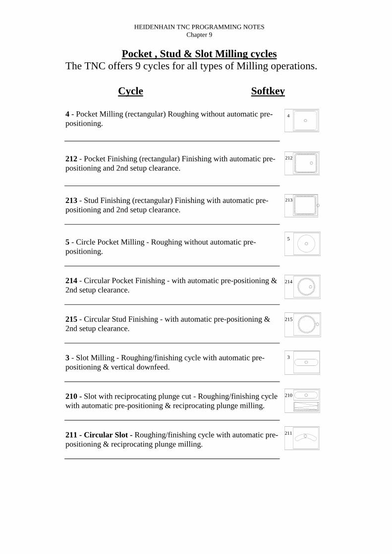
Pocket , Stud & Slot Milling cyclesThe TNC offers 9 cycles for all types of Milling operations.
Cycle Softkey
4 - Pocket Milling (rectangular) Roughing without automatic pre-positioning.
212 - Pocket Finishing (rectangular) Finishing with automatic pre-positioning and 2nd setup clearance.
213 - Stud Finishing (rectangular) Finishing with automatic pre-positioning and 2nd setup clearance.
5 - Circle Pocket Milling - Roughing without automatic pre-positioning.
214 - Circular Pocket Finishing - with automatic pre-positioning &2nd setup clearance.
215 - Circular Stud Finishing - with automatic pre-positioning &2nd setup clearance.
3 - Slot Milling - Roughing/finishing cycle with automatic pre-positioning & vertical downfeed.
210 - Slot with reciprocating plunge cut - Roughing/finishing cyclewith automatic pre-positioning & reciprocating plunge milling.
211 - Circular Slot - Roughing/finishing cycle with automatic pre-positioning & reciprocating plunge milling.
4
212
213
5
214
215
3
210
211

HEIDENHAIN TNC PROGRAMMING NOTESChapter 9
Linear Pocket Milling (Cycle 4)1) The tool penetrates the workpiece at the starting position (pocket center) andadvances to the first PECKING DEPTH.2) The cutter begins milling in the positive axis direction of the longer side (onsquare pockets, always starting in the positive Y axis) and then roughs out thepocket from the inside out.3) This process (1 - 3) is repeated until the DEPTH is reached.4) At the end of the cycle, the TNC retracts the tool to the starting position.
NOTE: Program a positioning block for the starting point (pocket center) in theworking plane with RADIUS COMPENSATION RO.
Program a positioning block for the starting point in the tool axis (SET-UPCLEARANCE above the workpiece surface).
The sign (+ or -) for the cycle parameter MILLING DEPTH determines the workingdirection.
This cycle requires a center cutting endmill or a pilot hole drilled prior to the Pocketmilling cycle.
⇒ SETUP CLEARANCE - (Incremental) Distance between tool tip (at startposition) and workpiece surface.
⇒ MILLING DEPTH - (Incremental) Distance between workpiece surface andbottom of the pocket.
⇒ PECKING DEPTH - (Incremental) Infeed per cut. The tool will advance tothe DEPTH in one movement if :a) the PECKING DEPTH equals the TOTALHOLE DEPTH. b) the PECKING DEPTH is greater than the MILLING DEPTH.
⇒ FEED RATE FOR PECKING - Pecking feedrate of the tool during penetration.⇒ FIRST SIDE LENGTH - Pocket length parallel to the main axis of the working
plane.⇒ SECOND SIDE LENGTH - Pocket width.⇒ FEED RATE F - Milling feedrate.⇒ DIRECTION OF THE MILLING PATH - DR+ = Climb milling with M3,
DR- = Conventional milling with M3.
The stepover factor is parameter (7430) and is preset by the machine manufacturers.

HEIDENHAIN TNC PROGRAMMING NOTESChapter 9
Linear Pocket Finishing (Cycle 212)1) The TNC automatically moves the tool in the tool axis to SET-UPCLEARANCE, or - if programmed - to the 2ND SET-UP CLEARANCE, andsubsequently to the center of the pocket.2) From the pocket center, the tool moves in the working plane to the starting pointfor machining. The TNC takes the ALLOWANCE and the tool radius into accountfor calculating the starting point. If necessary, the TNC plunge cuts into the pocketcenter.3) If the tool is at the 2ND SET-UP CLEARANCE, it moves in rapid traverseFMAX to SET-UP CLEARANCE, and from there advances to the first PLUNGINGDEPTH at the FEED RATE FOR PLUNGING.4) The tool then moves tangential to the contour of the finished part and, usingclimb milling, machines one revolution.5) After this, the tool departs the contour tangential and returns to the starting pointin the working plane.6) This process (3 - 5) is repeated until the programmed DEPTH is reached.7) At the end of the cycle, the TNC retracts the tool in rapid traverse to SET-UPCLEARANCE, or - if programmed - to the 2ND SET-UP CLEARANCE, andfinally to the center of the pocket (end position = starting position).
NOTE: The sign (+ or -) for the cycle parameter DEPTH determines the workingdirection.This cycle requires a center cutting endmill if it is being used to rough and finish (alow plunging feedrate will be required).Minimum size of pocket: 3 x tool radius.
⇒ SETUP CLEARANCE Q200 - (Incremental) Distance between tool tip (atstart position) and workpiece surface.
⇒ DEPTH Q201 - (Incremental) Distance between workpiece surface and bottomof the pocket.
⇒ FEED RATE FOR PLUNGING Q206 - Traversing speed of the tool whenmoving to DEPTH.
⇒ PLUNGING DEPTH Q202 - (Incremental) Infeed per cut.⇒ FEED RATE FOR MILLING Q207 - Pecking feedrate of the tool during
milling.⇒ WORKPIECE SURFACE COORDINATE Q203 - (Absolute) Coordinate of
workpiece surface.⇒ 2ND SET-UP CLEARANCE Q204 - (Incremental) Additional retract.⇒ CENTER IN FIRST AXIS Q216 - (Absolute) Center of the pocket in the main
axis of the working plane.⇒ CENTER IN SECOND AXIS Q217 - (Absolute) Center of the pocket in the
secondary axis of the working plane.⇒ FIRST SIDE LENGTH Q218 - Pocket length parallel to the main axis of the
working plane.⇒ SECOND SIDE LENGTH Q219 - Pocket width.⇒ CORNER RADIUS Q220 - Radius of the pocket corners. No value entered here
will use tool radius value.⇒ ALLOWANCE IN 1ST AXIS Q221 - (Incremental) Clearance value to allow
the tool diameter to rapid traverse close to the machined wall.

HEIDENHAIN TNC PROGRAMMING NOTESChapter 9
Linear Stud Finishing (Cycle 213)1) The TNC automatically moves the tool in the tool axis to SET-UPCLEARANCE, or - if programmed - to the 2ND SET-UP CLEARANCE, andsubsequently to the center of the stud.2) From the stud center, the tool moves in the working plane to the starting point formachining. The starting point lies to the right of the stud by a distance approx. 3.5times the tool radius.3) If the tool is at the 2ND SET-UP CLEARANCE, it moves in rapid traverseFMAX to SET-UP CLEARANCE, and from there advances to the first PLUNGINGDEPTH at the FEED RATE FOR PLUNGING.4) The tool then moves tangential to the contour of the finished part and, usingclimb milling, machines one revolution.5) After this, the tool departs the contour tangential and returns to the starting pointin the working plane.6) This process (3 - 5) is repeated until the programmed DEPTH is reached.7) At the end of the cycle, the TNC retracts the tool in rapid traverse to SET-UPCLEARANCE, or - if programmed - to the 2ND SET-UP CLEARANCE, andfinally to the center of the pocket (end position = starting position).
NOTE: The sign (+ or -) for the cycle parameter DEPTH determines the workingdirection.This cycle requires a center cutting endmill if it is being used to rough and finish (alow plunging feedrate will be required).
⇒ SETUP CLEARANCE Q200 - (Incremental) Distance between tool tip (atstart position) and workpiece surface.
⇒ DEPTH Q201 - (Incremental) Distance between workpiece surface and bottomof the stud.
⇒ FEED RATE FOR PLUNGING Q206 - Traversing speed of the tool whenmoving to DEPTH.
⇒ PLUNGING DEPTH Q202 - (Incremental) Infeed per cut.⇒ FEED RATE FOR MILLING Q207 - Feedrate of the tool during milling.⇒ WORKPIECE SURFACE COORDINATE Q203 - (Absolute) Coordinate of
workpiece surface.⇒ 2ND SET-UP CLEARANCE Q204 - (Incremental) Additional retract.⇒ CENTER IN FIRST AXIS Q216 - (Absolute) Center of the stud in the main
axis of the working plane.⇒ CENTER IN SECOND AXIS Q217 - (Absolute) Center of the stud in the
secondary axis of the working plane.⇒ FIRST SIDE LENGTH Q218 - Stud length parallel to the main axis of the
working plane.⇒ SECOND SIDE LENGTH Q219 - Stud width.⇒ CORNER RADIUS Q220 - Radius of the stud corners. No value entered here
will use tool radius value.⇒ ALLOWANCE IN 1ST AXIS Q221 - (Incremental) Clearance value to allow
the tool diameter to rapid traverse close to the machined wall.

HEIDENHAIN TNC PROGRAMMING NOTESChapter 9
Circular Pocket Milling (Cycle 5)1) The tool penetrates the workpiece at the starting position (pocket center) andadvances to the first PECKING DEPTH.2) The tool subsequently follows a spiral path at the FEED RATE F .3) This process is repeated until the DEPTH is reached.4) At the end of the cycle, the TNC retracts the tool to the starting position.
NOTE: Program a positioning block for the starting point (pocket center) in theworking plane with RADIUS COMPENSATION RO.
Program a positioning block for the starting point in the tool axis (SET-UPCLEARANCE above the workpiece surface).
The sign (+ or -) for the cycle parameter MILLING DEPTH determines the workingdirection.
This cycle requires a center cutting endmill or a pilot hole drilled prior to the Pocketmilling cycle.
⇒ SETUP CLEARANCE - (Incremental) Distance between tool tip (at startposition) and workpiece surface.
⇒ MILLING DEPTH - (Incremental) Distance between workpiece surface andbottom of the pocket.
⇒ PECKING DEPTH - (Incremental) Infeed per cut. The tool will advance tothe DEPTH in one movement if :a) the PECKING DEPTH equals the TOTALHOLE DEPTH. b) the PECKING DEPTH is greater than the MILLING DEPTH.
⇒ FEED RATE FOR PECKING - Pecking feedrate of the tool during penetration.⇒ CIRCULAR RADIUS - Radius of the required circular pocket.⇒ FEED RATE F - Milling feedrate.⇒ DIRECTION OF THE MILLING PATH - DR+ = Climb milling with M3,
DR- = Conventional milling with M3.
The stepover factor is parameter (7430) and is preset by the machine manufacturers.

HEIDENHAIN TNC PROGRAMMING NOTESChapter 9
Circular Pocket Finishing (Cycle 214)1) The TNC automatically moves the tool in the tool axis to SET-UPCLEARANCE, or - if programmed - to the 2ND SET-UP CLEARANCE, andsubsequently to the center of the pocket.2) From the pocket center, the tool moves in the working plane to the starting pointfor machining. The TNC takes the WORKPIECE BLANK DIAMETER and the toolradius into account for calculating the starting point. If a value of 0 is entered thenthe TNC plunge cuts into the pocket center.3) If the tool is at the 2ND SET-UP CLEARANCE, it moves in rapid traverseFMAX to SET-UP CLEARANCE, and from there advances to the first PLUNGINGDEPTH at the FEED RATE FOR PLUNGING.4) The tool then moves tangential to the contour of the finished part and, usingclimb milling, machines one revolution.5) After this, the tool departs the contour tangential and returns to the starting pointin the working plane.6) This process (4 - 5) is repeated until the programmed DEPTH is reached.7) At the end of the cycle, the TNC retracts the tool in rapid traverse to SET-UPCLEARANCE, or - if programmed - to the 2ND SET-UP CLEARANCE, andfinally to the center of the pocket (end position = starting position).
NOTE: The sign (+ or -) for the cycle parameter DEPTH determines the workingdirection.This cycle requires a center cutting endmill if it is being used to rough and finish (alow plunging feedrate will be required).
⇒ SETUP CLEARANCE Q200 - (Incremental) Distance between tool tip (atstart position) and workpiece surface.
⇒ DEPTH Q201 - (Incremental) Distance between workpiece surface and bottomof the pocket.
⇒ FEED RATE FOR PLUNGING Q206 - Traversing speed of the tool whenmoving to DEPTH.
⇒ PLUNGING DEPTH Q202 - (Incremental) Infeed per cut.⇒ FEED RATE FOR MILLING Q207 - Pecking feedrate of the tool during
milling.⇒ WORKPIECE SURFACE COORDINATE Q203 - (Absolute) Coordinate of
workpiece surface.⇒ 2ND SET-UP CLEARANCE Q204 - (Incremental) Additional retract.⇒ CENTER IN FIRST AXIS Q216 - (Absolute) Center of the pocket in the main
axis of the working plane.⇒ CENTER IN SECOND AXIS Q217 - (Absolute) Center of the pocket in the
secondary axis of the working plane.⇒ WORKPIECE BLANK DIAMETER Q222 - Diameter of the premachined
pocket. Enter the workpiece blank diameter to be less than the diameter of thefinished part. if a value of 0 is entered then the TNC plunge cuts in the pocketcenter.
⇒ FINISHED PART DIAMETER Q223 - Diameter of the finished pocket andmust be greater than the workpiece blank diameter.

HEIDENHAIN TNC PROGRAMMING NOTESChapter 9
Circular Stud Finishing (Cycle 215)1) The TNC automatically moves the tool in the tool axis to SET-UPCLEARANCE, or - if programmed - to the 2ND SET-UP CLEARANCE, andsubsequently to the center of the stud.2) From the stud center, the tool moves in the working plane to the starting point formachining. The starting point lies to the right of the stud by a distance approx. 3.5times the tool radius.3) If the tool is at the 2ND SET-UP CLEARANCE, it moves in rapid traverseFMAX to SET-UP CLEARANCE, and from there advances to the first PLUNGINGDEPTH at the FEED RATE FOR PLUNGING.4) The tool then moves tangential to the contour of the finished part and, usingclimb milling, machines one revolution.5) After this, the tool departs the contour tangential and returns to the starting pointin the working plane.6) This process (4 - 5) is repeated until the programmed DEPTH is reached.7) At the end of the cycle, the TNC retracts the tool in rapid traverse to SET-UPCLEARANCE, or - if programmed - to the 2ND SET-UP CLEARANCE, andfinally to the center of the pocket (end position = starting position).
NOTE: The sign (+ or -) for the cycle parameter DEPTH determines the workingdirection.This cycle requires a center cutting endmill if it is being used to rough and finish (alow plunging feedrate will be required).
⇒ SETUP CLEARANCE Q200 - (Incremental) Distance between tool tip (atstart position) and workpiece surface.
⇒ DEPTH Q201 - (Incremental) Distance between workpiece surface and bottomof the stud.
⇒ FEED RATE FOR PLUNGING Q206 - Traversing speed of the tool whenmoving to DEPTH.
⇒ PLUNGING DEPTH Q202 - (Incremental) Infeed per cut.⇒ FEED RATE FOR MILLING Q207 - Pecking feedrate of the tool during
milling.⇒ WORKPIECE SURFACE COORDINATE Q203 - (Absolute) Coordinate of
workpiece surface.⇒ 2ND SET-UP CLEARANCE Q204 - (Incremental) Additional retract.⇒ CENTER IN FIRST AXIS Q216 - (Absolute) Center of the stud in the main
axis of the working plane.⇒ CENTER IN SECOND AXIS Q217 - (Absolute) Center of the stud in the
secondary axis of the working plane.⇒ WORKPIECE BLANK DIAMETER Q222 - Diameter of the premachined
stud. Enter the workpiece blank diameter to be less than the diameter of thefinished part. if a value of 0 is entered then the TNC plunge cuts in the studcenter.
⇒ FINISHED PART DIAMETER Q223 - Diameter of the finished stud and mustbe greater than the workpiece blank diameter.

HEIDENHAIN TNC PROGRAMMING NOTESChapter 9
Slot Milling (Cycle 3)Roughing Process1) The TNC moves the tool inward by the milling allowance (half the differencebetween the slot width and the tool diameter). From there it plunge cuts into theworkpiece and mills in the longitudinal direction of the slot.2) After downfeed at the end of the slot, milling is performed in the oppositedirection. This process is repeated until the programmed MILLING DEPTH isreached.
Finishing process3) The TNC advances the tool at the slot bottom on a tangential arc to the outsidecontour. The tool climb mills the contour with M3.4) The tool is retracted in rapid traverse FMAX to SET-UP CLEARANCE.
NOTE: Program a positioning block for the starting point in the working plane - tothe center of the slot (second side length) and, within the slot, offset by the toolradius - with RADIUS COMPENSATION RO.
Program a positioning block for the starting point in the tool axis (SET-UPCLEARANCE above the workpiece surface).
The sign (+ or -) for the cycle parameter MILLING DEPTH determines the workingdirection.
This cycle requires a center cutting endmill or a pilot hole drilled prior to the Pocketmilling cycle.
The cutter diameter must not be larger than the SLOT WIDTH and not smaller thanhalf the SLOT WIDTH.
⇒ SETUP CLEARANCE - (Incremental) Distance between tool tip (at startposition) and workpiece surface.
⇒ MILLING DEPTH - (Incremental) Distance between workpiece surface andbottom of the pocket.
⇒ PECKING DEPTH - (Incremental) Infeed per cut. The tool will advance tothe DEPTH in one movement if :a) the PECKING DEPTH equals the TOTALHOLE DEPTH. b) the PECKING DEPTH is greater than the MILLING DEPTH.
⇒ FEED RATE FOR PECKING - Pecking feedrate of the tool during penetration.⇒ FIRST SIDE LENGTH - Pocket length parallel to the main axis of the working
plane.⇒ SECOND SIDE LENGTH - Pocket width.⇒ FEED RATE F - Milling feedrate.

HEIDENHAIN TNC PROGRAMMING NOTESChapter 9
Slot Milling with reciprocating plunge cut (Cycle 210)Roughing Process1) At rapid traverse, the TNC positions the tool in the tool axis to the 2ND SET-UPCLEARANCE and subsequently to the center of the left circle. From there, the TNCpositions the tool to SET-UP CLEARANCE above the workpiece surface.2) The tool moves at the FEEDRATE FOR MILLING to the workpiece surface.From there, the cutter advances in the longitudinal direction of the slot - plungecutting obliquely into the material - until it reaches the center of the right circle.3) The tool then moves back to the center of the left circle, again with obliqueplunge cutting. This process is repeated until the programmed MILLING DEPTH isreached.4) At the MILLING DEPTH, the TNC moves the tool for the purpose of facemillingto the other end of the slot and then back to the center of the slot.Finishing process5) The TNC advances the tool from the slot center tangential to the contour of thefinished part. The tool subsequently climb mills the contour (with M3).6) When the tool reaches the end of the contour, it departs the contour tangential andreturns to the center of the slot.7) At the end of the cycle, the tool is retracted in rapid traverse to the SET-UPCLEARANCE and - if programmed - to the 2ND SET-UP CLEARANCE.
NOTE: The sign (+ or -) for the cycle parameter MILLING DEPTH determines theworking direction.The cutter diameter must not be larger than the SLOT WIDTH and not smaller thana third of the SLOT WIDTH.The cutter diameter must also be at least half the slot length.
⇒ SETUP CLEARANCE Q200 - (Incremental) Distance between tool tip (atstart position) and workpiece surface.
⇒ DEPTH Q201 - (Incremental) Distance between workpiece surface and bottomof the stud.
⇒ FEED RATE FOR MILLING Q207 - Traversing speed of the tool whenmilling.
⇒ PLUNGING DEPTH Q202 - (Incremental) Infeed per cut (pecking).⇒ MACHINING OPERATION (0/1/2) Q215 - Define the type of operation: 0 =
Roughing and Finishing, 1 = Roughing only, 2 = Finishing only.⇒ WORKPIECE SURFACE COORDINATE Q203 - (Absolute) Coordinate of
workpiece surface.⇒ 2ND SET-UP CLEARANCE Q204 - (Incremental) Additional retract.⇒ CENTER IN FIRST AXIS Q216 - (Absolute) Center of the stud in the main
axis of the working plane.⇒ CENTER IN SECOND AXIS Q217 - (Absolute) Center of the stud in the
secondary axis of the working plane.⇒ FIRST SIDE LENGTH Q218 - Slot length parallel to the main axis of the
working plane.⇒ SECOND SIDE LENGTH Q219 - Slot width. If a value is entered that equals
the tool diameter, the TNC will perform a roughing out process only.⇒ ANGLE OF ROTATION Q224 - (Absolute ) Angle by which the entire slot is
rotated. The center of rotation lies in the center of the slot.

HEIDENHAIN TNC PROGRAMMING NOTESChapter 9
Circular Slot with reciprocating plunge cut (Cycle 210)Roughing Process1) At rapid traverse, the TNC positions the tool in the tool axis to the 2ND SET-UPCLEARANCE and subsequently to the center of the right circle. From there, theTNC positions the tool to SET-UP CLEARANCE above the workpiece surface.2) The tool moves at the FEEDRATE FOR MILLING to the workpiece surface.From there, the cutter advances in the longitudinal direction of the slot - plungecutting obliquely into the material - until it reaches the center of the left circle.3) The tool then moves at a downward angle back to the starting point. This processis repeated until the programmed MILLING DEPTH is reached.4) At the MILLING DEPTH, the TNC moves the tool for the purpose of facemillingto the other end of the slot.Finishing process5) The TNC advances the tool tangential to the contour of the finished part. The toolsubsequently climb mills the contour (with M3). The starting point being the righthand circle.6) When the tool reaches the end of the contour, it departs the contour tangential.7) At the end of the cycle, the tool is retracted in rapid traverse to the SET-UPCLEARANCE and - if programmed - to the 2ND SET-UP CLEARANCE.
NOTE: The sign (+ or -) for the cycle parameter MILLING DEPTH determines theworking direction.The cutter diameter must not be larger than the SLOT WIDTH and not smaller thana third of the SLOT WIDTH.The cutter diameter must also be at least half the slot length.
⇒ SETUP CLEARANCE Q200 - (Incremental) Distance between tool tip (atstart position) and workpiece surface.
⇒ DEPTH Q201 - (Incremental) Distance between workpiece surface and bottomof the stud.
⇒ FEED RATE FOR MILLING Q207 - Traversing speed of the tool whenmilling.
⇒ PLUNGING DEPTH Q202 - (Incremental) Infeed per cut (pecking).⇒ MACHINING OPERATION (0/1/2) Q215 - Define the type of operation: 0 =
Roughing and Finishing, 1 = Roughing only, 2 = Finishing only.⇒ WORKPIECE SURFACE COORDINATE Q203 - (Absolute) Coordinate of
workpiece surface.⇒ 2ND SET-UP CLEARANCE Q204 - (Incremental) Additional retract.⇒ CENTER IN FIRST AXIS Q216 - (Absolute) Center of the slot in the main
axis of the working plane.⇒ CENTER IN SECOND AXIS Q217 - (Absolute) Center of the slot in the
secondary axis of the working plane.⇒ PITCH CIRCLE DIAMETER Q244 - Diameter of the slot center PCD⇒ SECOND SIDE LENGTH Q219 - Slot width. If a value is entered that equals
the tool diameter, the TNC will perform a roughing out process only.⇒ STARTING ANGLE Q224 - (Absolute ) Polar angle starting point.⇒ ANGULAR LENGTH Q248 - (Incremental) Angular length of the slot.

HEIDENHAIN TNC PROGRAMMING NOTESChapter 9
(Slotting Cycle Exercise PGM 10117)
20
80
10
80
50
10
10
100 SQR.
20

HEIDENHAIN TNC PROGRAMMING NOTESChapter 9
(Slotting Cycle PGM 10117 text)
20
80
10
80
50
10
10
100 SQR.
20
0 BEGIN PGM 10117 MM1 BLK FORM 0.1 Z X+0 Y+0 Z-402 BLK FORM 0.2 X+100 Y+100 Z+03 TOOL DEF 14 TOOL CALL 1 Z S10005 L M66 CYCL DEF 3.0 SLOT MILLING7 CYCL DEF 3.1 SET UP 28 CYCLE DEF 3.2 DEPTH -209 CYCLE DEF 3.3 PECKG -10 F8010 CYCLE DEF 3.4 Y+8011 CYCLE DEF 3.5 X+1012 CYCL DEF 3.6 F50013 L X+20 Y+0 R0 FMAX M314 L Z+2 FMAX15 L Y+10 R+ FMAX16 CYCL CALL M817 CYCL DEF 3.0 SLOT MILLING18 CYCL DEF 3.1 SET UP 219 CYCLE DEF 3.2 DEPTH -2020 CYCLE DEF 3.3 PECKG -10 F8021 CYCLE DEF 3.4 X+5022 CYCLE DEF 3.5 Y+1023 CYCL DEF 3.6 F50024 L X+20 Y+15 FMAX25 L X+30 R+ FMAX M9926 TOOL CALL 027 L M628 L M3029 END PGM 10117 MM

HEIDENHAIN TNC PROGRAMMING NOTESChapter 9
(Pocket Exercise PGM 10118)
CORNER RADS 7.5mm
100 SQR.
40
20
50
50
80
50 30 DIA.

HEIDENHAIN TNC PROGRAMMING NOTESChapter 9
(Milling exercise PGM 10118)
CORNER RADS 7.5mm
100 SQR.
40
20
50
50
80
50 30 DIA.
0 BEGIN PGM 10118 MM1 BLK FORM 0.1 Z X+0 Y+0 Z-402 BLK FORM 0.2 X+100 Y+100 Z+03 TOOL DEF 14 TOOL CALL 1 Z S10005 L M66 CYCL DEF 4.0 POCKET MILLING7 CYCL DEF 4.1 SET UP 58 CYCL DEF 4.2 DEPTH -209 CYCL DEF 4.3 PECKG -10 F8010 CYCL DEF 4.4 X+8011 CYCL DEF 4.5 Y+5012 CYCL DEF 4.6 F500 DR+13 L X+50 Y+50 R0 FMAX M314 L Z+2 FMAX15 CYCL CALL M816 CYCL DEF 5.0 CIRCULAR POCKET17 CYCL DEF 5.1 SET UP -218 CYCLE DEF 5.2 DEPTH -2019 CYCLE DEF 5.3 PECKG -10 F20020 CYCLE DEF 5.4 RADIUS +1521 CYCLE DEF 5.5 F500 DR+22 L Z-18 FMAX M9923 CYCL CALL24 TOOL CALL 025 L M626 L M3027 END PGM 10118 MM

HE
IDE
NH
AIN
TN
C P
RO
GR
AM
MIN
G N
OT
ES
Cha
pter
9
(Poc
ket E
xerc
ise
PG
M 1
0119
)
100
SQ
R.
80 S
QR
.
50
45
90
40 Dia.
60 Dia.
20
50
10
30

HEIDENHAIN TNC PROGRAMMING NOTESChapter 9
(External Stud, Circular Pocket and Circular Slot exercise PGM 10119 text)
100 SQR.
80 SQR.
50
45
90
40 D
ia.
60 D
ia.
20
50
10
30
0 BEGIN PGM 10119 MM1 BLK FORM 0.1 Z X+0 Y+0 Z-402 BLK FORM 0.2 X+100 Y+100 Z+03 TOOL DEF 14 TOOL DEF 25 TOOL CALL 1 Z S10006 L M67 CYCL DEF 213 STUD FINISHING
Q200 = 2 ;SET-UP CLEARANCEQ201 = 30 ;DEPTHQ206 = 250 ;FEED RATE FOR PLNGNGQ202 = 5 ;PLUNGING DEPTHQ207 = 250 ;FEEDRATE FOR MILLINGQ203 = 0 ;SURFACE COORDINATEQ204 = 20 ;2ND SET-UP CLEARANCEQ216 = 50 ;CENTER IN 1ST AXISQ217 = 50 ;CENTER IN 2ND AXISQ218 = 80 ;FIRST SIDE LENGTHQ219 = 80 ;SECOND SIDE LENGTHQ220 = 0 ;CORNER RADIUSQ221 = 10 ;ALLOWANCE IN 1ST AXIS
8 L X+50 Y+50 R0 FMAX M39 L Z+5 FMAX10 CYCL CALL M8

HEIDENHAIN TNC PROGRAMMING NOTESChapter 9
11 CYCL DEF 5.0 CIRCULAR POCKET12 CYCL DEF 5.1 SET UP 213 CYCLE DEF 5.2 DEPTH -3014 CYCLE DEF 5.3 PECKG -10 F20015 CYCLE DEF 5.4 RADIUS +2016 CYCLE DEF 5.5 F500 DR+17 L X+0 Y+0 Z+2 R0 FMAX M9918 TOOL CALL 2 Z S100019 L M620 L X+0 Y+0 R0 FMAX M321 CYCL DEF 211 CIRCULAR SLOT
Q200 = 2 ;SET-UP CLEARANCEQ201 = -20 ;DEPTHQ207 = 250 ;FEEDRATE FOR MILLNGQ202 = 5 ;PLUNGING DEPTHQ215 = 0 ;MACHINING OPERATIONQ203 = 0 ;SURFACE COORDINATEQ204 = 100 ;2ND SET-UP CLEARANCEQ216 = 50 ;CENTER IN 1ST AXISQ217 = 50 ;CENTER IN 2ND AXISQ244 = 60 ;PITCH CIRCLE DIAMETRQ219 = 10 ;SECOND SIDE LENGTHQ245 = +45 ;STARTING ANGLEQ248 = 90 ;ANGULAR LENGTH
22 CYCLE CALL M823 CYCL DEF 211 CIRCULAR SLOT
Q200 = 2 ;SET-UP CLEARANCEQ201 = -20 ;DEPTHQ207 = 250 ;FEEDRATE FOR MILLNGQ202 = 5 ;PLUNGING DEPTHQ215 = 0 ;MACHINING OPERATIONQ203 = 0 ;SURFACE COORDINATEQ204 = 100 ;2ND SET-UP CLEARANCEQ216 = 50 ;CENTER IN 1ST AXISQ217 = 50 ;CENTER IN 2ND AXISQ244 = 70 ;PITCH CIRCLE DIAMETRQ219 = 8 ;SECOND SIDE LENGTHQ245 = +225 ;STARTING ANGLEQ248 = 90 ;ANGULAR LENGTH
24 CYCLE CALL M25 TOOL CALL 026 L M627 L M3028 END PGM 10119 MM

HEIDENHAIN TNC PROGRAMMING NOTESChapter 9
Area Clearance cycles SL1 & SL2The TNC offers 2 cycles for Area Clearance operations.
Cycle Softkey
14 (SLI & SLII) - Contour Geometry (Essential)
15 (SLI) - Pilot Drilling (Optional)
6 (SLI) - Rough Out (Essential)
16 (SLI) - Contour Milling (Optional)
20 (SLII) - Contour Data (Essential)
21 (SLII) - Pilot Drilling (Optional)
22 (SLII) - Rough-Out (Essential)
23 (SLII) - Floor Finishing (Optional)
24 (SLII) - Side Finishing (Optional)
14
LBL 1 . . . N
15
6
16
20CONTOUR
DATA
21
22
23
24

HEIDENHAIN TNC PROGRAMMING NOTESChapter 9
Area Clearance cycles SL
SL Cycles allows the machining of non-uniformed contours and can include islandsand pockets.
A machined pocket can be composed of a maximum of 12 sub-contours.
The subcontours are stored as label numbers entered into Cycle 14 CONTOURGEOMETRY. The TNC calculates all the machining areas to be cleared from theinformation stored in these labels.
The SL cycle has a memory capacity of 128 blocks of information.
Characteristics of the labels⇒ Coordinate transformations are allowed.⇒ The TNC ignores all feed rates and M functions.⇒ Compensation is applied directly on the first positioning line of the label.
Characteristics of the Fixed Cycles⇒ The actual positioning to the working plane must be done first. The TNC
automatically positions the tool to the starting position of the pocket.The TNC takes into account any finishing values contained in the Cycle 6 ROUGHOUT.
Contour Geometry (Cycle 14)
Note: Cycle 14 is DEF active which means that it becomes effective as soon as itis defined in the part program.
A maximum of 12 label numbers are permissible.
All labels must be assigned after the M2 program block
⇒ LABEL NUMBERS FOR THE CONTOUR:Enter all the label numbers for the individual subprograms that are to be superimposedto define the contour. Confirm every label number with the ENT key. When allnumbers are entered conclude with the END key.
14
LBL 1 . . . N

HEIDENHAIN TNC PROGRAMMING NOTESChapter 9
Pilot Drill (Cycle 15)
ProcessSame as Cycle 1 Pecking.ApplicationCycle 15 is for PILOT DRILLING of the cutter infeed points. It accounts for theALLOWANCE FOR SIDE and the ALLOWANCE FOR FLOOR. The cutter infeedpoints also serve as starting points for roughing.
Note: A positioning block to the machining surface is required.
⇒ SET-UP CLEARANCE - (Incremental) Distance between the tool tip and theworkpiece surface.
⇒ TOTAL HOLE DEPTH - (Incremental) Distance between the workpiece surfaceand the hole bottom.
⇒ PECKING DEPTH - (Incremental) Infeed per cut. The tool will cut in one depthif the value of the PECKING DEPTH is equal to the TOTAL HOLE DEPTH.
⇒ FEED RATE FOR PECKING - Traversing feed.⇒ FINISHING ALLOWANCE - (Incremental)
15

HEIDENHAIN TNC PROGRAMMING NOTESChapter 9
Rough-Out (Cycle 6)
Process1) The TNC positions the tool above the first cutter infeed point in the machiningplane, taking into account any FINISHING ALLOWANCE.2) The TNC then moves the tool to the first PECKING DEPTH at the FEED RATEFOR PECKING.
The contour is then fully roughed out by machining the external contours of all thelabels data first, then the remaining material. The machining takes place at thePECKING DEPTH. When an internal contour (island) is met by the tool, the tool willrapid traverse to SET-UP CLEARANCE, rapid traverse to the next milled contourspace and infeed to the pecking depth to continue. This process continues untilMILLING DEPTH is reached.
Note: A positioning block to the machining surface is required.
A center cutting endmill is required if the PILOT DRILLING cycle is not used.
⇒ SET-UP CLEARANCE - (Incremental) Distance between the tool tip and theworkpiece surface.
⇒ MILLING HOLE DEPTH - (Incremental) Distance between the workpiecesurface and the pocket floor.
⇒ PECKING DEPTH - (Incremental) Infeed per cut. The tool will cut in one depthif the value of the PECKING DEPTH is equal to the TOTAL HOLE DEPTH.
⇒ FEED RATE FOR PECKING - Traversing feed during penetration.⇒ FINISHING ALLOWANCE - (Incremental)⇒ ROUGH-OUT ANGLE - Direction of the roughing-out movement. Enter the
angle to allow the cutter to cut as long as possible.⇒ FEED RATE - Traversing feed during milling.
6

HEIDENHAIN TNC PROGRAMMING NOTESChapter 9
Contour Milling (Cycle 16)
ApplicationCycle 16 CONTOUR MILLING is used as the finishing cycle for the contour pocket.
Note: A positioning block to the machining surface is required.
A center cutting endmill is required if the MILLING DEPTH is not the sameMILLING DEPTH in the ROUGH-OUT cycle (cycle 6).
⇒ SET-UP CLEARANCE - (Incremental) Distance between the tool tip and theworkpiece surface.
⇒ MILLING DEPTH - (Incremental) Distance between the workpiece surface andthe pocket floor.
⇒ PECKING DEPTH - (Incremental) Infeed per cut. The tool will cut in one depthif the value of the PECKING DEPTH is equal to the TOTAL HOLE DEPTH.
⇒ FEED RATE FOR PECKING - Traversing feed during penetration.⇒ CLOCKWISE ROTATION DR+ Climb milling with M3 DR- Conventional Milling with M3⇒ FEED RATE - Traversing feed during milling.
16

HEIDENHAIN TNC PROGRAMMING NOTESChapter 9
SLII CYCLES - Contour Data (Cycle 20)Machining data for the stored labels.
Note: Cycle 20 is DEF active which means that it becomes effective as soon as itis defined in the part program.The machining data entered here is applicable only for cycles 14, & 21 to 24If Q parameters are to be used Q1 to Q19 cannot be used as programparameters.
⇒ MILLING DEPTH - (Incremental) Distance between workpiece surface andpocket bottom.
⇒ PATH OVERLAP FACTOR - Percentage value of cutter radius stepover whilstmilling.
⇒ FINISHING ALLOWANCE FOR SIDE - (Incremental)⇒ FINISHING ALLOWANCE FOR FLOOR - (Incremental)⇒ WORKPIECE SURFACE COORDINATE - (Absolute) Surface coordinates.⇒ SET-UP CLEARANCE - (Incremental) Distance between the tool tip and the
workpiece surface.⇒ CLEARANCE HEIGHT - (Absolute) Height at which the tool cannot collide
with the workpiece. when traversing to another position.⇒ INSIDE CORNER RADIUS - Arcing ON radius.⇒ DIRECTION OF ROTATION -1 = Conventional Milling +1 = Climb Milling
Pilot Drill (Cycle 21)ProcessSame as Cycle 1 Pecking.ApplicationCycle 15 is for PILOT DRILLING of the cutter infeed points. It accounts for theALLOWANCE FOR SIDE and the ALLOWANCE FOR FLOOR. The cutter infeedpoints also serve as starting points for roughing.
⇒ PECKING DEPTH - (Incremental) Infeed per cut. The tool will cut in one depthif the value of the PECKING DEPTH is equal to the TOTAL HOLE DEPTH.
⇒ FEED RATE FOR PECKING - Traversing feed.⇒ ROUGH-OUT TOOL NUMBER - Roughing out tool number
20CONTOUR
DATA
21

HEIDENHAIN TNC PROGRAMMING NOTESChapter 9
Rough-Out (Cycle 22)
Process1) The TNC positions the tool above the first cutter infeed point in the machiningplane, taking into account any FINISHING ALLOWANCE.2) The TNC then moves the tool to the first PECKING DEPTH at the FEED RATEFOR PECKING.
The contour is then fully roughed out by machining the external contours of all thelabels data first, then the remaining material. The machining takes place at thePECKING DEPTH. When an internal contour (island) is met by the tool, the tool willmachine around the island contour. This process continues until MILLING DEPTH isreached.
Note:
A center cutting endmill is required if the PILOT DRILLING cycle is not used.
⇒ PECKING DEPTH - (Incremental) Infeed per cut. The tool will cut in one depthif the value of the PECKING DEPTH is equal to the TOTAL HOLE DEPTH.
⇒ FEED RATE FOR PECKING - Traversing feed during penetration.⇒ FEED RATE FOR MILLING - Traversing feed during milling.⇒ COURSE ROUGHING TOOL NUMBER - The number of the tool with which
the TNC has already course roughed the contour. If the contour has not beencoursed roughed, enter zero. If you enter a value other than zero, the TNC will onlyrough out the portion that could not be machined with the course roughing tool. Ifthe portion that is to be fine-roughed cannot be approached from the side, the TNCwill mill in a reciprocating plunge cuts. F or this purpose, you must enter the toothlength LCUTS and the maximum plunge angle of the tool in the tool tableTOOL.T.. The TNC will otherwise generate a message.
⇒ RECIPROCATING FEED RATE - Traversing feed of the tool whilst plunge-cutting.
22

HEIDENHAIN TNC PROGRAMMING NOTESChapter 9
Floor Finishing (Cycle 23)
Note: The TNC automatically calculates the starting point for finishing.
⇒ FEED RATE FOR PECKING - Traversing feed during penetration.⇒ FEED RATE FOR MILLING - Traversing feed during milling.
Side Finishing (Cycle 24)The subcontours are approached and departed on a tangential arc. Each subcontouredis finished separately.
Note: The sum of the ALLOWANCE FOR SIDE and the radius of the finishmilling cutter must be smaller than the sum of ALLOWANCE FOR SIDE and
the radius of the roughing milling cutter.
The TNC automatically calculates the starting points.
⇒ DIRECTION OF ROTATION -1 = Conventional Milling +1 = Climb Milling⇒ PECKING DEPTH - (Incremental)⇒ FEED RATE FOR PECKING - Traversing feed during penetration.⇒ FEED RATE FOR MILLING - Traversing feed during milling.⇒ FINISHING ALLOWANCE - (Incremental) Enter the allowed material for
several finishing passes or zero for one finish pass to completion.
23
24

HEIDENHAIN TNC PROGRAMMING NOTESChapter 9
(Island Clearance Exercise PGM 10120)
100 SQR.
16
16
35
16
50
16
65
25 R (x2)
Pocket = 20mm Deep

HEIDENHAIN TNC PROGRAMMING NOTESChapter 9
(Island Clearance Exercise PGM 10120)0 BEGIN PGM 10120 MM1 BLK FORM 0.1 Z X+0 Y+0 Z-402 BLK FORM 0.2 X+100 Y+100 Z+03 TOOL DEF 14 TOOL DEF 25 TOOL DEF 36 CYCL DEF 14.0 CONTOUR GEOM.7 CYCL DEF 14.1 CONTOUR LABEL 1/2/3/4/ / /8 TOOL CALL 1 Z S5009 L M610 CYCL DEF 15.0 PILOT DRILL11 CYCL DEF 15.1 SET UP -2 DEPTH -2012 CYCL DEF 15.2 PECKG -10 F50 ALLOW +113 L X+0 Y+0 R0 FMAX M1314 L Z+2 FMAX M9915 TOOL CALL 2 Z S100016 L M617 CYCL DEF 6.0 ROUGH OUT18 CYCL DEF 6.1 SET UP -2 DEPTH -2019 CYCL DEF 6.2 PECKG -10 F50 ALLOW +120 CYCL DEF 6.3 ANGLE +45 F20021 L X+0 Y+0 R0 FMAX M1322 L Z+2 FMAX23 CYCL CALL M24 TOOL CALL 3 Z S100025 L M626 CYCL DEF 16.0 CONTOUR MILLG27 CYCL DEF 16.1 SET UP -2 DEPTH -2028 CYCL DEF 16.2 PECKG -20 F50 DR+ F20029 L X+0 Y+0 R0 FMAX M330 L Z+2 FMAX31 CYCL CALL M32 TOOL CALL 033 L M634 L M3035 LBL 136 L X+35 Y+25 RL F M37 CC X+35 Y+5038 C X+35 Y+25 DR+39 LBL 040 LBL 241 L X+65 Y+25 RL42 CC X+65 Y+5043 C X+65 Y+25 DR+44 LBL 045 LBL 346 L X+35 Y+42 RL47 L X+2748 L Y+5849 L X+4350 L Y+4251 L X+3552 LBL 053 LBL 454 L X+65 Y+42 RL55 L X+5756 L X+65 Y+5857 L X+73 Y+4258 L X+6559 LBL 060 END PGM 10120 MM

HEIDENHAIN TNC PROGRAMMING NOTESChapter 9
Enhanced SLII cyclesThe TNC offers 2 cycles for ease of face milling & milling
contours.
Cycle Softkey
25 - Contour Train
27 - Cylinder Surface (4th axis option)
230 - Multi-pass Milling
25
27
230
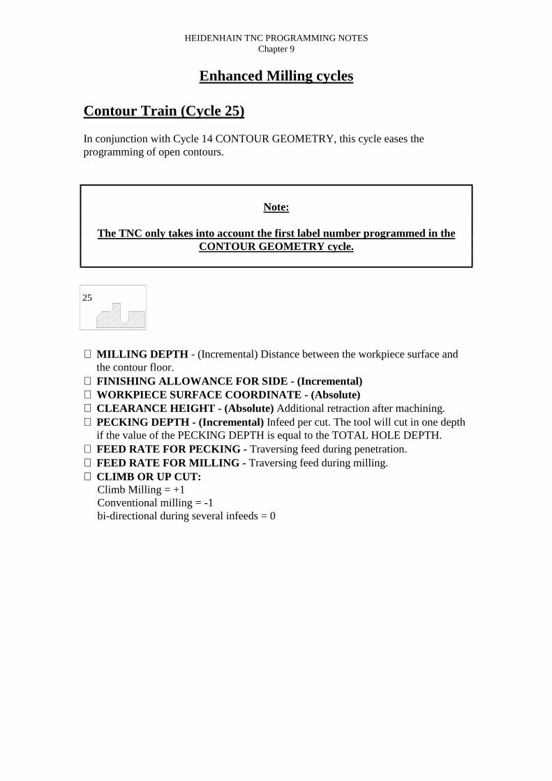
HEIDENHAIN TNC PROGRAMMING NOTESChapter 9
Enhanced Milling cycles
Contour Train (Cycle 25)
In conjunction with Cycle 14 CONTOUR GEOMETRY, this cycle eases theprogramming of open contours.
Note:
The TNC only takes into account the first label number programmed in theCONTOUR GEOMETRY cycle.
⇒ MILLING DEPTH - (Incremental) Distance between the workpiece surface andthe contour floor.
⇒ FINISHING ALLOWANCE FOR SIDE - (Incremental)⇒ WORKPIECE SURFACE COORDINATE - (Absolute)⇒ CLEARANCE HEIGHT - (Absolute) Additional retraction after machining.⇒ PECKING DEPTH - (Incremental) Infeed per cut. The tool will cut in one depth
if the value of the PECKING DEPTH is equal to the TOTAL HOLE DEPTH.⇒ FEED RATE FOR PECKING - Traversing feed during penetration.⇒ FEED RATE FOR MILLING - Traversing feed during milling.⇒ CLIMB OR UP CUT: Climb Milling = +1 Conventional milling = -1 bi-directional during several infeeds = 0
25

HEIDENHAIN TNC PROGRAMMING NOTESChapter 9
Cylinder Surface (Cycle 27) - 4th axis
This cycle enables you to program a contour in two dimensions and then roll it onto acylindrical surface for 3d machining.
In conjunction with Cycle 14 CONTOUR GEOMETRY, this cycle eases theprogramming of cylindrical contours.
The subprogram (label) contains coordinates in a rotary axis and in its parallel axis.The rotary axis C for example is parallel to the Z axis. The path functions L, CHF, CRand RND are available for programming.
The dimensions in the rotary axis can be entered as either degrees or in linearmeasurements MM / INCH selected in the cycle definition.
Note:
The TNC only takes into account the first label number programmed in theCONTOUR GEOMETRY cycle.
The initial positioning to the work piece surface must first be established.
⇒ MILLING DEPTH - (Incremental) Distance between the workpiece surface andthe contour floor.
⇒ FINISHING ALLOWANCE FOR SIDE - (Incremental)⇒ SET-UP CLEARANCE - (Incremental) Distance between the tool tip and the
cylinder surface.⇒ PECKING DEPTH - (Incremental) Infeed per cut. The tool will cut in one depth
if the value of the PECKING DEPTH is equal to the TOTAL HOLE DEPTH.⇒ FEED RATE FOR PECKING - Traversing feed during penetration.⇒ FEED RATE FOR MILLING - Traversing feed during milling.⇒ RADIUS - Radius of the cylinder.⇒ DIMENSION TYPE Degrees = 0 Linear Measurements = 1
27

HEIDENHAIN TNC PROGRAMMING NOTESChapter 9
Multi-pass Milling (Cycle 230)
1) From the current position, the TNC positions the tool in rapid traverse in theworking plane to the starting position. During this movement, the TNC also offsetsthe tool by its radius to the left and upwards.2) The tool then moves in FMAX in the tool axis to SET-UP CLEARANCE. Fromthere it approaches the programmed starting position in the tool axis at the FEEDRATE FOR PLUNGING.3) The tool then advances along the machining surface. The end point is calculatedtaking into account the starting point, the programmed length and the tool radius.4) The TNC offsets the tool to the next starting point for the next pass at theSTEPOVER FEED RATE. The offset is calculated from the programmed width andthe number of cuts.5) Multipass Milling is repeated until the programmed surface has been completed.6) At the end of the cycle, the tool is retracted in FMAX to SET-UP CLEARANCE.
⇒ STARTING POINT IN THE 1ST AXIS - (Absolute) MINIMUM pointcoordinate of the surface to be machined as the main axis.
⇒ STARTING POINT IN THE 2ND AXIS - (Absolute) MINIMUM pointcoordinate of the surface to be machined as the secondary axis
⇒ STARTING POINT IN THE 3RD AXIS - (Absolute) HEIGHT in the spindleaxis to be the finished value when machining has been completed.
⇒ FIRST SIDE LENGTH - (Incremental) Length of the surface to be machined inthe main axis, referenced to the STARTING POINT IN THE 1ST AXIS.
⇒ SECOND SIDE LENGTH - (Incremental) Length of the surface to be machinedin the secondary axis, referenced to the STARTING POINT IN THE 2ND AXIS.
⇒ NUMBER OF CUTS - Number of passes to be made over the width.⇒ PECKING DEPTH - (Incremental) Infeed per cut. The tool will cut in one depth
if the value of the PECKING DEPTH is equal to the TOTAL HOLE DEPTH.⇒ FEED RATE FOR PLUNGING - Traversing feed from SET-UP to the milling
depth.⇒ FEED RATE FOR MILLING - Traversing feed during milling.⇒ STEP OVER FEED RATE - Traversing feed of the tool when moving from one
pass to the next.⇒ SET-UP CLEARANCE - (Incremental) Distance between the tool tip and the
milling depth for positioning at the beginning and end of the cycle.
230

HEIDENHAIN TNC PROGRAMMING NOTESChapter 9
(Contour Train Exercise PGM 10121)
1520
75
95
7.5 RAD
550
100
0 BEGIN PGM 10121 MM1 BLK FORM 0.1 Z X0 Y0 Z-402 BLK FORM 0.2 X100 Y100 Z03 TOOL DEF 14 TOOL CALL 1 Z S10005 L M66 L Z250 R0 FMAX7 CYCL DEF 14.0 CONTOUR GEOMETRY8 CYCL DEF 14.1 CONTOUR LABEL 19 CYCL DEF 25.0 CONTOUR TRAIN Q1 = -20 ; MILLING DEPTH Q3 = 0 ; ALLOWANCE FOR SIDE Q5 = 0 ; SURFACE COORDINATE Q7 = 250; CLEARANCE HEIGHT Q10 = 5 ; PECKING DEPTH Q11 = 100 ; FEED RATE FOR PECKING Q12 = 200 ; FEED RATE FOR MILLING Q15 = 1 ; CLIMB OR UP-CUT10 CYCL CALL M311 L Z250 R0 FMAX M3012 LBL 113 L X0 Y15 RL14 L X5 Y2015 CT X5 Y7516 L Y9517 RND R7.518 L X5019 L X100 Y8020 LBL 021 END PGM 10121 MM

HEIDENHAIN TNC PROGRAMMING NOTESChapter 9
(Cylinder Surface Exercise PGM 10122)
20
60
5030
7.5 R
157
X
A
0 BEGIN PGM 10122 MM1 TOOL DEF 12 TOOL CALL 1 X S20003 L M64 L X250 R0 FMAX5 CYCL DEF 14.0 CONTOUR GEOMETRY6 CYCL DEF 14.1 CONTOUR LABEL 17 CYCL DEF 27.0 CYLINDER SURFACE Q1 = -7 ;MILLING DEPTH Q3 = 0 ;ALLOWANCE FOR SIDE Q6 = 2 ;SET-UP CLEARANCE Q10 = 4 ;PECKING DEPTH Q11 = 100 ;FEED RATE FOR PECKING Q12 = 250 ;FEED RATE FOR MILLING Q16 = 25 ;RADIUS Q17 = 1 DIMENSION TYPE (ANG/LIN)8 L A0 R0 FMAX M39 CYCL CALL10 L Z250 R0 FMAX M3011 LBL 112 L A40 X20 RL13 L A5014 RND R7.515 L X6016 RND R7.517 L IA-2018 RND R7.519 L X2020 RND R7.521 L A4022 LBL 023 END PGM 10122 MM

HEIDENHAIN TNC PROGRAMMING NOTESChapter 9
(Multipass Milling Exercise PGM 10123)
Y Y
ZX100
100
35
0 BEGIN PGM 10123 MM1 BLK FORM 0.1 Z X0 Y0 Z02 BLK FORM 0.2 X100 Y100 Z403 TOOL DEF 14 TOOL CALL 1 Z S20005 L M66 L Z250 R0 FMAX7 CYCL DEF 230 MULTIPASS MILLING Q225 = 0 ;STARTING POINT 1ST AXIS Q226 = 0 ;STARTING POINT 2ND AXIS Q227 = 35 ;STARTING POINT 3RD AXIS Q218 = 100 ;FIRST SIDE LENGTH Q219 = 100 ;SECOND SIDE LENGTH Q240 = 25 ;NUMBER OF CUTS Q206 = 250 ;FEED RATE FOR PLNGNG Q207 = 400 ;STEPOVER FEED RATE Q202 = 2 ;SET-UP CLEARANCE8 L X-25 Y0 R0 FMAX M39 CYCL CALL10 L Z250 R0 FMAX M3011 END PGM 10123 MM

HEIDENHAIN TNC PROGRAMMING NOTESChapter 10
CHAPTER 10

HEIDENHAIN TNC PROGRAMMING NOTESChapter 10
Pattern cyclesThe TNC offers 2 cycles for machining hole patterns.
Cycle Softkey
220 - Circular Pattern.
221 - Linear Pattern.
You can combine Cycle 220 and Cycle 221 with the following fixed cycles:Cycle 1 PeckingCycle 2 TappingCycle 3 Slot MillingCycle 4 Pocket MillingCycle 5 Circular Pocket MillingCycle 17 Rigid TappingCycle 200 DrillingCycle 201 ReamingCycle 202 BoringCycle 203 Universal DrillingCycle 209 Chip breaking tappingCycle 212 Pocket FinishingCycle 213 Stud FinishingCycle 214 Circular Pocket FinishingCycle 215 Circular Stud Finishing
220
221

HEIDENHAIN TNC PROGRAMMING NOTESChapter 10
Circular Pattern (Cycle 220)
1) At rapid traverse, the TNC positions the tool from its current position to thestarting point for the first machining operation.The tool is positioned in the following sequence:a) Move to 2ND SET-UP CLEARANCEb) Approach starting point in the working plane.c) Move to SET-UP CLEARANCE above the workpiece surface.2) From this position the TNC executes the last defined fixed cycle.3) The tool then approaches the starting point for the next machining operation on astraight line at SET-UP CLEARANCE (or 2ND SET-UP CLEARANCE).4) The process (1 - 3) is repeated until all maching operations have been executed.
NOTE: Cycle 220 is DEF active, which means that it automatically calls the lastdefined fixed cycle.
If Cycle220 is combined with one of the fixed cycles 200 - 215, the SET-UPCLEARANCE, workpiece surface and 2ND SET-UP CLEARANCE that youdefined in Cycle 220 will be effective for the selected fixed cycle.
⇒ CENTRE IN 1ST AXIS Q216 (Absolute) - Centre of the Pitch Circle in themain axis of the working plane.
⇒ CENTRE IN 2ND AXIS Q217 - (Absolute) Centre of the Pitch Circle in thesecondary axis of the working plane.
⇒ PITCH CIRCLE DIAMETER Q244 - Diameter of the PCD.⇒ STARTING ANGLE Q245 - (Absolute Polar) Angle between the main axis of
the working plane and the starting point for the first machining operation on thePCD.
⇒ STOPPING ANGLE Q246 (Absolute Polar) - Angle between the main axis ofthe working plane and the starting point for the last machining operation on thePCD. Do not enter the same value for the STOPPING ANGLE and STARTINGANGLE. If you enter the STOPPING ANGLE greater than the STARTINGANGLE machining will be carried out counterclockwise, otherwise machiningwill be clockwise.
⇒ STEPPING ANGLE Q247 - (Incremental) Angle between two machiningoperations on a PCD. If a zero value is entered, the TNC will calculate theSTEPPING ANGLE from the STARTING and STOPPING ANGLES. If a valueother than zero is entered, the TNC will not take into account the STOPPINGANGLE. The sign for the STEPPING ANGLE determines the working direction(- = clockwise).
⇒ NUMBER OF REPETITIONS Q241 - Number of machining operations on aPCD.
⇒ SETUP CLEARANCE Q200 - (Incremental) Distance between tool tip (atstart position) and workpiece surface.
⇒ WORKPIECE SURFACE COORDINATE Q203 - (Absolute) Coordinate ofworkpiece surface.
⇒ 2ND SET-UP CLEARANCE Q204 - (Incremental) Additional retraction.

HEIDENHAIN TNC PROGRAMMING NOTESChapter 10
Linear Pattern (Cycle 221)
1) At rapid traverse, the TNC positions the tool from its current position to thestarting point for the first machining operation.The tool is positioned in the following sequence:a) Move to 2ND SET-UP CLEARANCEb) Approach starting point in the working plane.c) Move to SET-UP CLEARANCE above the workpiece surface.2) From this position the TNC executes the last defined fixed cycle.3) The tool then approaches the starting point for the next machining operation on astraight line at SET-UP CLEARANCE (or 2ND SET-UP CLEARANCE).4) The process (1 - 3) is repeated until all maching operations have been executed.The tool is located above the last point on the first line.5) The tool subsequently moves to the last point on the second line where it carriesout the machining operation.6) From this position the tool approaches the starting point for the next machiningoperation in the negative main axis direction.7) This process (5 - 6) is repeated until all machining operations in the second linehave been completed.8) The tool then moves to the starting point of the next line.9) All subsequent lines are processed in a reciprocating movement.
NOTE: Cycle 220 is DEF active, which means that it automatically calls the lastdefined fixed cycle.
If Cycle220 is combined with one of the fixed cycles 200 - 215, the SET-UPCLEARANCE, workpiece surface and 2ND SET-UP CLEARANCE that youdefined in Cycle 220 will be effective for the selected fixed cycle.
⇒ STARTING POINT 1ST AXIS Q225 (Absolute) - Starting point coordinate inthe main axis of the working plane.
⇒ STARTING POINT 2ND AXIS Q226 - (Absolute) Starting point coordinate inthe secondary axis of the working plane.
⇒ SPACING IN 1ST AXIS Q237 - (Incremental) Pitch per column.⇒ SPACING IN 2ND AXIS Q238 - (Incremental) Pitch per row.⇒ NUMBER OF COLUMNS Q242 - Number of columns to be machined.⇒ NUMBER OF LINES Q243 - Number of rows to be machined.⇒ ANGLE OF ROTATION Q224 - (Absolute) Angle by which the entire pattern
is rotated. The centre of rotation lies at the pattern starting point.⇒ SETUP CLEARANCE Q200 - (Incremental) Distance between tool tip (at
start position) and workpiece surface.⇒ WORKPIECE SURFACE COORDINATE Q203 - (Absolute) Coordinate of
workpiece surface.⇒ 2ND SET-UP CLEARANCE Q204 - (Incremental) Additional retraction.

HEIDENHAIN TNC PROGRAMMING NOTESChapter 10
(Circular Pattern PGM 10124)
120 2045.00°
36
3085
35
M6
70

HEIDENHAIN TNC PROGRAMMING NOTESChapter 10
(Circular Pattern PGM 10124)
120 2045.00°
36
3085
35
M6
70
0 BEGIN PGM 10124 MM1 BLK FORM 0.1 Z X+0 Y+0 Z-202 BLK FORM 0.2 X+120 Y+70 Z+03 TOOL DEF 14 TOOL DEF 25 TOOL DEF 36 TOOL CALL 1 Z S5007 L M68 L M139 CYCL DEF 1.0 PECKING10 CYCL DEF 1.1 SET UP 211 CYCL DEF 1.2 DEPTH -212 CYCL DEF 1.3 PECKG -213 CYCL DEF 1.4 DWELL 014 CYCL DEF 1.5 F20015 CYCL DEF 220 POLAR PATTERN
Q216 = 30 ;CENTRE IN 1ST AXISQ217 = 35 ;CENTER IN 2ND AXISQ244 = 36 ;PITCH CIRCLE DIAMETRQ245 = 0 ;STARTING ANGLEQ246 = 360 ;STOPPING ANGLEQ247 = 0 ;STEPPING ANGLEQ241 = 8 ;NR OF REPETITIONSQ200 = 2 ;SET-UP CLEARANCEQ203 = 0 ;SURFACE COORDINATEQ204 = 100 ;2ND SET-UP CLEARANCE

HEIDENHAIN TNC PROGRAMMING NOTESChapter 10
16 CYCL DEF 220 POLAR PATTERNQ216 = 85 ;CENTRE IN 1ST AXISQ217 = 35 ;CENTER IN 2ND AXISQ244 = 36 ;PITCH CIRCLE DIAMETRQ245 = 0 ;STARTING ANGLEQ246 = 360 ;STOPPING ANGLEQ247 = 0 ;STEPPING ANGLEQ241 = 8 ;NR OF REPETITIONSQ200 = 2 ;SET-UP CLEARANCEQ203 = 0 ;SURFACE COORDINATEQ204 = 100 ;2ND SET-UP CLEARANCE
17 TOOL CALL 2 Z S100018 L M619 L M1320 CYCL DEF 1.0 PECKING21 CYCL DEF 1.1 SET UP 222 CYCL DEF 1.2 DEPTH -2023 CYCL DEF 1.3 PECKG 1024 CYCL DEF 1.4 DWELL 025 CYCL DEF 1.5 F20026 CYCL DEF 220 POLAR PATTERN
Q216 = 30 ;CENTRE IN 1ST AXISQ217 = 35 ;CENTER IN 2ND AXISQ244 = 36 ;PITCH CIRCLE DIAMETRQ245 = 0 ;STARTING ANGLEQ246 = 360 ;STOPPING ANGLEQ247 = 0 ;STEPPING ANGLEQ241 = 8 ;NR OF REPETITIONSQ200 = 2 ;SET-UP CLEARANCEQ203 = 0 ;SURFACE COORDINATEQ204 = 100 ;2ND SET-UP CLEARANCE
27 CYCL DEF 220 POLAR PATTERNQ216 = 85 ;CENTRE IN 1ST AXISQ217 = 35 ;CENTER IN 2ND AXISQ244 = 36 ;PITCH CIRCLE DIAMETRQ245 = 0 ;STARTING ANGLEQ246 = 360 ;STOPPING ANGLEQ247 = 0 ;STEPPING ANGLEQ241 = 8 ;NR OF REPETITIONSQ200 = 2 ;SET-UP CLEARANCEQ203 = 0 ;SURFACE COORDINATEQ204 = 100 ;2ND SET-UP CLEARANCE
28 TOOL CALL 3 Z S50029 L M630 L M13

HEIDENHAIN TNC PROGRAMMING NOTESChapter 10
33 CYCL DEF 2.0 TAPPING34 CYCL DEF 2.1 SET UP 235 CYCL DEF 2.2 DEPTH -2036 CYCL DEF 2.3 DWELL 037 CYCL DEF 2.4 F47532 CYCL DEF 220 POLAR PATTERN
Q216 = 30 ;CENTRE IN 1ST AXISQ217 = 35 ;CENTER IN 2ND AXISQ244 = 36 ;PITCH CIRCLE DIAMETRQ245 = 0 ;STARTING ANGLEQ246 = 360 ;STOPPING ANGLEQ247 = 0 ;STEPPING ANGLEQ241 = 8 ;NR OF REPETITIONSQ200 = 2 ;SET-UP CLEARANCEQ203 = 0 ;SURFACE COORDINATEQ204 = 100 ;2ND SET-UP CLEARANCE
33 CYCL DEF 220 POLAR PATTERNQ216 = 85 ;CENTRE IN 1ST AXISQ217 = 35 ;CENTER IN 2ND AXISQ244 = 36 ;PITCH CIRCLE DIAMETRQ245 = 0 ;STARTING ANGLEQ246 = 360 ;STOPPING ANGLEQ247 = 0 ;STEPPING ANGLEQ241 = 8 ;NR OF REPETITIONSQ200 = 2 ;SET-UP CLEARANCEQ203 = 0 ;SURFACE COORDINATEQ204 = 100 ;2ND SET-UP CLEARANCE
34 TOOL CALL 035 L M636 L M3037 END PGM 10124 MM

HEIDENHAIN TNC PROGRAMMING NOTESChapter 10
(Grid Pattern Exercise PGM 10125)
10mm Pitch
10m
m P
itch
100 SQR.
15
10
20
6mm Holes

HEIDENHAIN TNC PROGRAMMING NOTESChapter 10
(Linear Pattern Exercise PGM 10125)
10mm Pitch
10m
m P
itch
100 SQR.
15
10
20
6mm Holes
0 BEGIN PGM 10125 MM1 BLK FORM 0.1 Z X+0 Y+0 Z-202 BLK FORM 0.2 X+100 Y+100 Z+03 TOOL DEF 1 L+0 R+34 TOOL CALL 1 Z S5005 L M66 L X+15 Y+10 R0 FMAX M137 CYCL DEF 1.0 PECKING8 CYCL DEF 1.1 SET UP 29 CYCL DEF 1.2 DEPTH -2010 CYCL DEF 1.3 PECKG -2011 CYCL DEF 1.4 DWELL 012 CYCL DEF 1.5 F20013 CYCL DEF 221 CARTESIAN PATTERN
Q225 = 15 ;STARTNG PNT 1ST AXISQ226 = 10 ;STARTNG PNT 2ND AXISQ237 = 10 ;SPACING IN 1ST AXISQ238 = 10 ;SPACING IN 2ND AXISQ242 = 8 ;NUMBER OF COLUMNSQ243 = 9 ;NUMBER OF LINESQ224 = 0 ;ANGLE OF ROTATIONQ200 = 2 ;SET-UP CLEARANCEQ203 = 0 ;SURFACE COORDINATEQ204 = 100 ;2ND SET-UP CLEARANCE
14 TOOL CALL 015 L M616 L M3017 END PGM 10125 MM

HEIDENHAIN TNC PROGRAMMING NOTESChapter 10
Coordinate Transformations cyclesOnce a contour has been programmed, you can position it onthe workpiece at various locations and in different sizesthrough the use of coordinate transformations. The TNCprovides the following coordinate transformation cycles:
Cycle Softkey
7 - Datum Shift - For shifting contours directly within the programor from a Datum table.
8 - Mirror Image - For mirroring contours.
10 - Rotation - For rotating contours in the working plane.
11 - Scaling - For increasing or reducing the size of contours.
26 - Axis specific Scaling (TNC426 only) - For increasing orreducing specific axis on contours.
Effect of Coordinate Transformations:A coordinate transformation becomes effective as soon as it is defined. It remains ineffect until it is redefined or cancelled.
Coordinate Transformation CancellationCoordinate transformations are cancelled bya) redefining the default state i.e. Scaling = 1.0b) Execute a miscellaneous function M2, M30 or an End Of Program Block.c) Select a new program.
7
8
10
11
26

HEIDENHAIN TNC PROGRAMMING NOTESChapter 10
(Mirror Image Exercise PGM 10126)
60
5040
3020
2040
60 Holes 10mm x 20mm deep

HEIDENHAIN TNC PROGRAMMING NOTESChapter 10
(Mirror Image Exercise PGM 10126)
60
5040
3020
2040
60 Holes 10mm x 20mm deep
0 BEGIN PGM 10126 MM1 BLK FORM 0.1 Z X-65 Y-65 Z-202 BLK FORM 0.2 X+65 Y+65 Z+03 TOOL DEF 14 TOOL CALL 1 Z S10005 L M66 CYCL DEF 200 DRILLING
Q200 = 5 ;SET-UP CLEARANCEQ201 = -20 ;DEPTHQ206 = ??? ;FEED RATE FOR PLNGNGQ202 = 5 ;PLNGNG DEPTHQ210 = 0 ;DWELL TIME AT TOPQ203 = 0 ;SURFACE COORDINATEQ204 = 5 ;2ND SET-UP CLEARANCE
7 L X-20 Y+20 R0 FMAX M138 L Z+5 FMAX M899 L X-30 Y+40 FMAX10 L X-40 Y+60 FMAX11 L X-50 Y+40 FMAX12 L X-60 Y+20 FMAX13 CYCL DEF 8.0 MIRROR IMAGE14 CYCL DEF 8.1 X15 L X-20 Y+20 FMAX16 L X-30 Y+40 FMAX17 L X-40 Y+60 FMAX18 L X-50 Y+40 FMAX19 L X-60 Y+20 FMAX M9920 CYCL DEF 8.0 MIRROR IMAGE21 CYCL DEF 8.122 TOOL CALL 023 L M624 L M3025 END PGM 10126 MM

HEIDENHAIN TNC PROGRAMMING NOTESChapter 10
(Rotation Exercise PGM 10127)
100
100
Y
X
120
2010
15
All holes 20mm Deep

HEIDENHAIN TNC PROGRAMMING NOTESChapter 10
(Rotation Exercise PGM 10127 text)
100
100
Y
X
120
2010
15
All holes 20mm Deep
0 BEGIN PGM 10127 MM1 BLK FORM 0.1 Z X-50 Y-50 Z-402 BLK FORM 0.2 X+50 Y+50 Z+03 TOOL DEF 14 TOOL CALL 1 Z S10005 L M66 CYCL DEF 200 DRILLING
Q200 = 5 ;SET-UP CLEARANCEQ201 = -20 ;DEPTHQ206 = ??? ;FEED RATE FOR PLNGNGQ202 = 5 ;PLNGNG DEPTHQ210 = 0 ;DWELL TIME AT TOPQ203 = 0 ;SURFACE COORDINATEQ204 = 5 ;2ND SET-UP CLEARANCE
7 L X+20 Y+0 R0 FMAX M138 L Z+5 FMAX M899 L IX+10 FMAX10 L IX+15 FMAX11 CYCL DEF 10.0 ROTATION12 CYCL DEF 10.1 ROT+12013 L X+20 Y+0 FMAX14 L IX+10 FMAX15 L IX+15 FMAX16 CYCL DEF 10.0 ROTATION17 CYCL DEF 10.1 ROT+24018 L X+20 Y+0 FMAX19 L IX+10 FMAX20 L IX+15 FMAX M9921 CYCL DEF 10.0 ROTATION22 CYCL DEF 10.1 ROT+023 TOOL CALL 024 L M625 L M3026 END PGM 10127 MM

HEIDENHAIN TNC PROGRAMMING NOTESChapter 11
CHAPTER 11

HEIDENHAIN TNC PROGRAMMING NOTESChapter 11
(Sub-Programming)
Total number of labels = 254Total number of repeats = 9999Total number of nest levels = 8
BEGIN PGM
LBL 11
CALL LBL11 REP 2/2
END PGM
1 2 3
LBLSET
LBLCALL

HEIDENHAIN TNC PROGRAMMING NOTESChapter 11
(Sub-Programming)
LBL 0 = Sub-program end
Answer REP prompt with NO ENTER
BEGIN PGM
STOP M2
CALL LBL 27 REP
CALL LBL 27 REP
LBL 27
END PGM
1
3
5
2,4
LBL 0

HEIDENHAIN TNC PROGRAMMING NOTESChapter 11
(Sub-Programming)
BEGIN PGM
STOP M2
CALL LBL 19 REP
CALL LBL 20 REP
LBL 19
END PGM
1
3
5
2
LBL 0LBL 20
LBL 0
4

HEIDENHAIN TNC PROGRAMMING NOTESChapter 11
(Sub-Programming)
BEGIN PGM
CALL LBL 27 REP
LBL 27
LBL 0
1
2
4
END PGM
3

HEIDENHAIN TNC PROGRAMMING NOTESChapter 11
(Sub-Programming - REPEATS)
*THE WRONG METHOD*
BEGIN PGM
CALL LBL 27 REP 2/2
LBL 27
LBL 0
1
END PGM
3
2
This reads text between the LBL0 & LBL REP

HEIDENHAIN TNC PROGRAMMING NOTESChapter 11
(Sub-Programming - REPEATS)
*THE RIGHT METHOD*#1
BEGIN PGM
LBL 81 REP
LBL 27
LBL 0
1
CALL LBL 81 REP
32
CALL LBL 27 REPLBL 0
END PGM

HEIDENHAIN TNC PROGRAMMING NOTESChapter 11
(Sub-Programming - REPEATS)
*THE RIGHT METHOD*#2
BEGIN PGM
LBL 81 REP
LBL 27
LBL 0
1
CALL LBL 81 REP 5/5
2
CALL LBL 27 REPLBL 0
END PGM
3 4 5 6 7

HEIDENHAIN TNC PROGRAMMING NOTESChapter 11
(Sub-Programming - NESTING)
BEGIN PGM
CALL LBL 15 REP
LBL 15
LBL 17
END PGM
CALL LBL 17 REP 2/2
3 4
62
5
1
7 8
9

HEIDENHAIN TNC PROGRAMMING NOTESChapter 11
(Repeat Exercise PGM 10128)
8 Holes (6mm Dia.)10mm Pitch
30
50
15
100
10

HEIDENHAIN TNC PROGRAMMING NOTESChapter 11
(Repeat exercise PGM 10128)
8 Holes (6mm Dia.)10mm Pitch
30
50
15
100
10
0 BEGIN PGM 10128 MM1 BLK FORM 0.1 Z X+0 Y+0 Z-402 BLK FORM 0.2 X+100 Y+50 Z+03 TOOL DEF 14 TOOL CALL 1 Z S10005 L M66 CYCL DEF 1.0 PECKING7 CYCL DEF 1.1 SET UP -28 CYCL DEF 1.2 DEPTH -209 CYCL DEF 1.3 PECKG -1010 CYCL DEF 1.4 DWELL 011 CYCL DEF 1.5 F50012 L X+15 Y+30 R0 FMAX M1313 L Z+2 FMAX M9914 LBL 115 L IX+10 FMAX M9916 CALL LBL 1 REP 6/617 TOOL CALL 018 L M619 L M3020 END PGM 10128 MM

HEIDENHAIN TNC PROGRAMMING NOTESChapter 11
(Sub-Program Exercise PGM 10129)
100
15
20
63
12
70
10 15 42
42
Holes 2mm x 20mm Deep

HEIDENHAIN TNC PROGRAMMING NOTESChapter 11
(Sub-Program Exercise PGM 10129)
100
15
20
63
12
70
10 15 42
42
Holes 2mm x 20mm Deep
0 BEGIN PGM 10129 MM1 BLK FORM 0.1 Z X+0 Y-70 Z-202 BLK FORM 0.2 X+100 Y+0 Z+03 TOOL DEF 14 TOOL CALL 1 Z S10005 L M66 CYCL DEF 1.0 PECKING7 CYCL DEF 1.1 SET UP 28 CYCL DEF 1.2 DEPTH -219 CYCL DEF 1.3 PECKG -510 CYCL DEF 1.4 DWELL 011 CYCL DEF 1.5 F10012 L X+20 Y-10 R0 FMAX M1313 L Z+2 FMAX M8914 CALL LBL 115 L X+42 Y-42 FMAX M8916 CALL LBL 117 L X+63 Y-10 FMAX M8918 CALL LBL 119 TOOL CALL 020 L M621 L M3022 LBL 123 L IX+15 FMAX24 L IY-15 FMAX25 L IX-15 FMAX M9926 LBL 027 END PGM 10129 MM

HEIDENHAIN TNC PROGRAMMING NOTESChapter 11
(Nesting Labels Exercise PGM 10130)
120 2045.00°
36
3085
35
M6
70
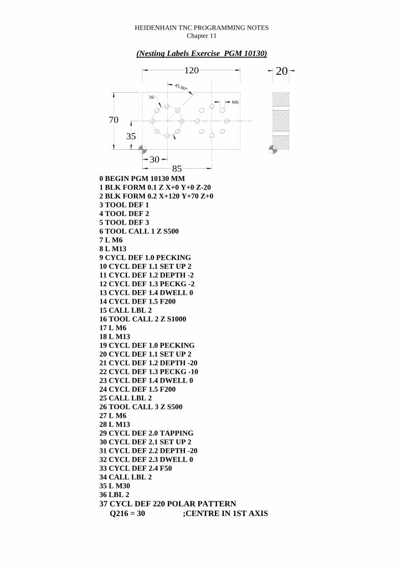
HEIDENHAIN TNC PROGRAMMING NOTESChapter 11
(Nesting Labels Exercise PGM 10130)
120 2045.00°
36
3085
35
M6
70
0 BEGIN PGM 10130 MM1 BLK FORM 0.1 Z X+0 Y+0 Z-202 BLK FORM 0.2 X+120 Y+70 Z+03 TOOL DEF 14 TOOL DEF 25 TOOL DEF 36 TOOL CALL 1 Z S5007 L M68 L M139 CYCL DEF 1.0 PECKING10 CYCL DEF 1.1 SET UP 211 CYCL DEF 1.2 DEPTH -212 CYCL DEF 1.3 PECKG -213 CYCL DEF 1.4 DWELL 014 CYCL DEF 1.5 F20015 CALL LBL 216 TOOL CALL 2 Z S100017 L M618 L M1319 CYCL DEF 1.0 PECKING20 CYCL DEF 1.1 SET UP 221 CYCL DEF 1.2 DEPTH -2022 CYCL DEF 1.3 PECKG -1023 CYCL DEF 1.4 DWELL 024 CYCL DEF 1.5 F20025 CALL LBL 226 TOOL CALL 3 Z S50027 L M628 L M1329 CYCL DEF 2.0 TAPPING30 CYCL DEF 2.1 SET UP 231 CYCL DEF 2.2 DEPTH -2032 CYCL DEF 2.3 DWELL 033 CYCL DEF 2.4 F5034 CALL LBL 235 L M3036 LBL 237 CYCL DEF 220 POLAR PATTERN
Q216 = 30 ;CENTRE IN 1ST AXIS

HEIDENHAIN TNC PROGRAMMING NOTESChapter 11
Q217 = 35 ;CENTER IN 2ND AXISQ244 = 36 ;PITCH CIRCLE DIAMETRQ245 = 0 ;STARTING ANGLEQ246 = 360 ;STOPPING ANGLEQ247 = 0 ;STEPPING ANGLEQ241 = 8 ;NR OF REPETITIONSQ200 = 2 ;SET-UP CLEARANCEQ203 = 0 ;SURFACE COORDINATEQ204 = 100 ;2ND SET-UP CLEARANCE
38 CYCL DEF 220 POLAR PATTERNQ216 = 85 ;CENTRE IN 1ST AXISQ217 = 35 ;CENTER IN 2ND AXISQ244 = 36 ;PITCH CIRCLE DIAMETRQ245 = 0 ;STARTING ANGLEQ246 = 360 ;STOPPING ANGLEQ247 = 0 ;STEPPING ANGLEQ241 = 8 ;NR OF REPETITIONSQ200 = 2 ;SET-UP CLEARANCEQ203 = 0 ;SURFACE COORDINATEQ204 = 100 ;2ND SET-UP CLEARANCE
39 LBL 040 END PGM 10130 MM

HEIDENHAIN TNC PROGRAMMING NOTESChapter 12
CHAPTER 12

HEIDENHAIN TNC PROGRAMMING NOTESChapter 12
Helical InterpolationA helix is a combination of a circular movement in a main plane and a linearmovement perpendicular to this plane.Applications1) Large-diameter internal and external threads.2) Lubrication grooves.
Programming a HelixAlways enter the same algebraic sign for the direction of rotation DR and theincremental total angle IPA. The tool may otherwise move in a wrong path anddamage the contour.
For the total angle IPA, you can enter a value from -5400 degrees to +5400degrees. If the thread has more than 15 revolutions, program the helix in aprogram section repeat.
⇒ POLAR COORDINATES-ANGLE - (Incremental) Enter the total angle oftool traversing along the helix. After entering the angle, identify the tool axiswith an axis selection key.
⇒ Enter the COORDINATE for the height of the helix in incremental dimensions.⇒ Direction of rotation DR- Counterclockwise, DR+ Clockwise⇒ RADIUS COMPENSATION R0/RL/RR according to the following table.
Internal ThreadRight-HandedLeft-Handed
Right-HandedLeft-Handed
External ThreadRight-HandedLeft-Handed
Right-HandedLeft-Handed
Work DirectionZ+Z+
Z-Z-
Work DirectionZ+Z+
Z-Z-
DirectionDR+DR-
DR-DR+
DirectionDR+DR-
DR-DR+
Radius Comp.RLRR
RRRL
Radius Comp.RRRL
RLRR
CC
C
P

HEIDENHAIN TNC PROGRAMMING NOTESChapter 12
(Helical Milling Exercise PGM 10125)
100
100
M68 x 3mm Pitch (42mm Deep)

HEIDENHAIN TNC PROGRAMMING NOTESChapter 12
(Helical Milling Exercise PGM 10125 text)
100
100
M68 x 3mm Pitch (42mm Deep)
0 BEGIN PGM 10131 MM1 BLK FORM 0.1 Z X+0 Y+0 Z-402 BLK FORM 0.2 X+100 Y+100 Z+03 TOOL DEF 14 TOOL DEF 25 TOOL CALL 1 Z S5006 L M67 CYCL DEF 1.0 PECKING8 CYCL DEF 1.1 SET UP 39 CYCL DEF 1.2 DEPTH -4010 CYCL DEF 1.3 PECKG -4011 CYCL DEF 1.4 DWELL 012 CYCL DEF 1.5 F10013 L X+0 Y+0 R0 FMAX M314 L Z+3 FMAX M2715 CYCL CALL16 TOOL CALL 2 Z S100017 L M618 X+0 Y+6.8 R0 FMAX M319 L Z-41.5 FMAX20 L IX+27.2 RL FMAX21 CC X+0 Y+022 CP IPA+90 IZ+1.5 DR+ F100 M823 CP IPA+5040 IZ+42 DR+24 CP IPA+90 IZ+1.5 DR+25 L IX+27.2 R0 FMAX26 L Z+100 FMAX M227 END PGM 10131 MM

HEIDENHAIN TNC PROGRAMMING NOTESChapter 13
CHAPTER 13

HEIDENHAIN TNC PROGRAMMING NOTESChapter 13
Tool Length Measurement methods
Methods of measuring the length of the tool from the gauge line (spindle nose) to thetool tip, for entry into the Tool Def. program line or into the length column of the tooltable.
1) Using the machine to measure the tool (with a setting block).a) traverse the spindle nose with no tool inserted and using a feeler block set thespindle nose to the top of the feeler block. Enter a datum set for the Z axis as Zero.
Setting Block
TABLE
SpindleFeeler Block
Z Datum set zero
b) Using MDI toolchange the appropriate tool requiring setting and traverse the tooltip to the feeler block. Using the “Program Editing” menu, highlight, using the left &right arrow keys, the L? part of the Tool Def. Line. Pressing the Data Transfer keywhile Z is highlighted in the position display will transfer the tool lengthautomatically.
Setting Block
TABLE

HEIDENHAIN TNC PROGRAMMING NOTESChapter 13
Tool Length Measurement methods
Methods of measuring the length of the tool from the gauge line (spindle nose) to thetool tip, for entry into the Tool Def. program line or into the length column of the tooltable.
2) Using the machine to measure the tool (using the component workpiece).
*NOTE: When using this method it is advisable that the longest tool is used to setthe Z axis zero (datum) position.
a) Using MDI toolchange the appropriate tool requiring setting and traverse the tooltip to the feeler block. Using the “Program Editing” menu, highlight, using the left &right arrow keys, the L? part of the Tool Def. Line. Pressing the Data Transfer keywhile Z is highlighted in the position display will transfer the tool lengthautomatically.When setting the datum using the longest tool, the L? value regarding this tool will bezero. All tools set after this to the workpiece will have a value which is relative to thesetting tool. If the setting tool has to be changed for any reason then all tools will have
to be reset.
Component
TABLE

HEIDENHAIN TNC PROGRAMMING NOTESChapter 13
Tool Length Measurement methods
Methods of measuring the length of the tool from the gauge line (spindle nose) to thetool tip, for entry into the Tool Def. program line or into the length column of the tooltable.
3) Using a tool height measuring system.
0.000
Gauge Height Length
The tool length and radius (if required) is now input into the Tool Def L? value of theappropriate program line.
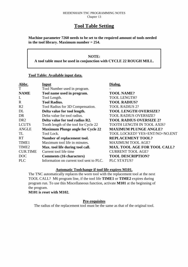
HEIDENHAIN TNC PROGRAMMING NOTESChapter 13
Tool Table Setting
Machine parameter 7260 needs to be set to the required amount of tools neededin the tool library. Maximum number = 254.
NOTE:A tool table must be used in conjunction with CYCLE 22 ROUGH MILL.
Tool Table: Available input data.
Abbr.TNAMELRR2DLDRDR2LCUTSANGLETLRTTIME1TIME2CUR.TIMEDOCPLC
InputTool Number used in program.Tool name used in program.Tool Length.Tool Radius.Tool Radius for 3D Compensation.Delta value for tool length.Delta value for tool radius.Delta value for tool radius R2.Tooth length of the tool for Cycle 22Maximum Plunge angle for Cycle 22Tool Lock.Number of replacement tool.Maximum tool life in minutes.Max. tool life during tool call.Current tool life timeComments (16 characters)Information on current tool sent to PLC.
Dialog.-TOOL NAME?TOOL LENGTH?TOOL RADIUS?TOOL RADIUS 2?TOOL LENGTH OVERSIZE?TOOL RADIUS OVERSIZE?TOOL RADIUS OVERSIZE 2?TOOTH LENGTH IN TOOL AXIS?MAXIMUM PLUNGE ANGLE?TOOL LOCKED? YES=ENT/NO=NO.ENTREPLACEMENT TOOL?MAXIMUM TOOL AGE?MAX. TOOL AGE FOR TOOL CALL?CURRENT TOOL AGE?TOOL DESCRIPTION?PLC STATUS?
Automatic Toolchange if tool life expires M101.The TNC automatically replaces the worn tool with the replacement tool at the nextTOOL CALL? M6 program line, if the tool life TIME1 or TIME2 expires duringprogram run. To use this Miscellaneous function, activate M101 at the beginning ofthe program.M101 is reset with M102.
Pre-requisitesThe radius of the replacement tool must be the same as that of the original tool.

HEIDENHAIN TNC PROGRAMMING NOTESChapter 17
CHAPTER 14

HEIDENHAIN TNC PROGRAMMING NOTESChapter 17
Datum Setting with Datum shiftsTo be set in “Manual” or “Handwheel” mode.
Maximum "X" Traverse
Max
imum
"Y
" T
rave
rse
DATUM SET
Machine Reference (G28)
DATUM SHIFT
To select Datum Shift via program:On selecting “Datum Shift” in the Co-ordinate Transfer cycle definitions “Enter” the
numeric value with the appropriate Axis.
Datum Shift “?” = Absolute distance from the “Current Datum to the part datum.
*Note:There is no limit to the amount of “Datum Shifts” which can be used in a program but
only one “Datum Set” can be used per program.
Cancelling a “Datum Shift”:On selecting “Datum Shift” in the Co-ordinate Transfer cycle definitions “Enter” the
numeric value of Zero in each of the Axis to be cancelled.

HEIDENHAIN TNC PROGRAMMING NOTESChapter 17
Datum Setting with Datum TablesTo be set in “Manual” or “Handwheel” mode.
Maximum "X" Traverse
Maximum "Y" Traverse
#1
Machine Reference (G28)
#2
To select Datum via program:
A “Datum Set” must be established at the “Machine Reference Position” beforeany part datum setting as L X0 Y0 M91
Values are transferred into the appropriate datum row in the correct axis using the“DATA TRANSFER” key.
On selecting “Datum Shift” in the Co-ordinate Transfer cycle definitions “Enter” the“ROW NUMBER”. The text would read as #??
The “Datum Table” must be activated via the “Test Run” mode by selecting theappropriate Datum Program and pressing “Enter”. The value “S” will be shown in the
STATUS column of the program library.

HEIDENHAIN TNC PROGRAMMING NOTESChapter 15
CHAPTER 15

HEIDENHAIN TNC PROGRAMMING NOTESChapter 15
(PGM FK1)
100 SQR.
R88
R25
R14
5050
R14

HEIDENHAIN TNC PROGRAMMING NOTESChapter 15
Heidenhain Flex K Programming
(PGM FK1)
100 SQR.
R88
R25
R14
5050
R14
0 BEGIN PGM FK1 MM1 BLK FORM 0.1 Z X-10 Y+0 Z-402 BLK FORM 0.2 X+110 Y+100 Z+03 TOOL DEF 1 L+0 R+54 TOOL CALL 1 Z S5005 L M66 L X+50 Y+50 R0 FMAX M37 L Z+2 FMAX8 L Z-10 F1009 L Y+75 RL F50010 FC DR+ R25 CCX+50 CCY+5011 FCT DR- R1412 FCT DR- R88 CCX+50 CCY013 FSELECT 114 FCT DR- R1415 FCT X+50 Y+75 DR+ R25 CCX+50 CCY+5016 FSELECT 217 L Y+50 R018 L Z+50 R0 FMAX M519 TOOL CALL 020 L M621 L M222 END PGM FK1 MM

HEIDENHAIN TNC PROGRAMMING NOTESChapter 15
Heidenhain Flex K Programming
(PGM FK1 Converted)
100 SQR.
R88
R25
R14
50
50
R14
0 BEGIN PGM FK1 MM1 BLK FORM 0.1 Z X-10 Y+0 Z-402 BLK FORM 0.2 X+110 Y+100 Z+03 TOOL DEF 1 L+0 R+54 TOOL CALL 1 Z S5005 L M66 L X+50 Y+50 R0 FMAX M37 L Z+2 FMAX8 L Z-10 F1009 L Y+75 RL F50010 CC X+50 Y+5011 C X+26.805 Y+59.327 DR+12 CC X+13.816 Y+64.5513 C X+6.97 Y+76.762 DR-14 CC X+50 Y+5015 C X+93.03 Y76.762 DR-16 CC X+86.184 Y+64.5517 C X+73.195 Y+59.327 DR-18 CC X+50 Y+5019 C X+50 Y+75 DR+20 L X+50 Y+50 R021 L Z+50 FMAX M522 TOOL CALL 0 Z S6023 L M624 L M225 END PGM FK1 MM

HEIDENHAIN TNC PROGRAMMING NOTESChapter 15
Heidenhain Flex K Programming
(PGM FK2)
75
50
20
2030
75
R15
R15
R18
100 SQR.
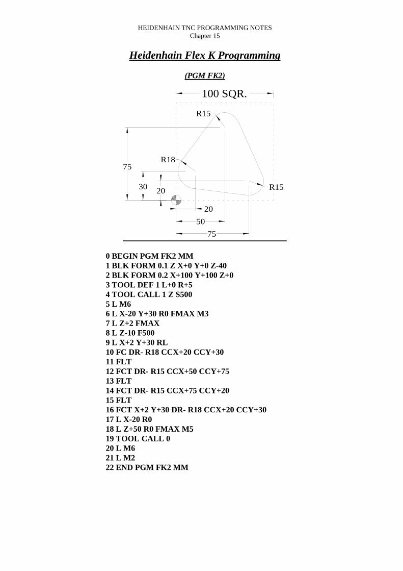
HEIDENHAIN TNC PROGRAMMING NOTESChapter 15
Heidenhain Flex K Programming
(PGM FK2)
75
50
20
2030
75
R15
R15
R18
100 SQR.
0 BEGIN PGM FK2 MM1 BLK FORM 0.1 Z X+0 Y+0 Z-402 BLK FORM 0.2 X+100 Y+100 Z+03 TOOL DEF 1 L+0 R+54 TOOL CALL 1 Z S5005 L M66 L X-20 Y+30 R0 FMAX M37 L Z+2 FMAX8 L Z-10 F5009 L X+2 Y+30 RL10 FC DR- R18 CCX+20 CCY+3011 FLT12 FCT DR- R15 CCX+50 CCY+7513 FLT14 FCT DR- R15 CCX+75 CCY+2015 FLT16 FCT X+2 Y+30 DR- R18 CCX+20 CCY+3017 L X-20 R018 L Z+50 R0 FMAX M519 TOOL CALL 020 L M621 L M222 END PGM FK2 MM

HEIDENHAIN TNC PROGRAMMING NOTESChapter 15
Heidenhain Flex K Programming
(PGM FK2 Converted)
75
50
20
2030
75
R15
R15
R18
100 SQR.
0 BEGIN PGM FK2 MM1 BLK FORM 0.1 Z X+0 Y+0 Z-402 BLK FORM 0.2 X+100 Y+100 Z+03 TOOL DEF 1 L+0 R+54 TOOL CALL 1 Z S5005 L M66 L X-20 Y+30 R0 FMAX M37 L Z+2 FMAX8 L Z-10 F5009 L X+2 Y+30 RL10 CC X+20 Y+3011 C X+5.6 Y+40.8 DR-12 L X+38 Y+8413 CC X+50 Y+7514 C X+63.656 Y+81.207 DR-15 L X+88.656 Y+26.20716 CC X+75 Y+2017 C X+73.113 Y+5.119 DR-18 L X+17.735 Y+12.14319 CC X+20 Y+3020 C X+2 Y+30 DR-21 L X-20 R022 L Z+50 R0 FMAX M523 TOOL CALL 0 Z S6024 L M625 L M226 END PGM FK2 MM

HEIDENHAIN TNC PROGRAMMING NOTESChapter 15
Heidenhain Flex K Programming
(PGM FK3)
12.7084.3
90.65
6.35
12.70 R
12.70
76.20
63.55
10.00 R
19.05
12.70 R
7.94 R
15.88
45.00
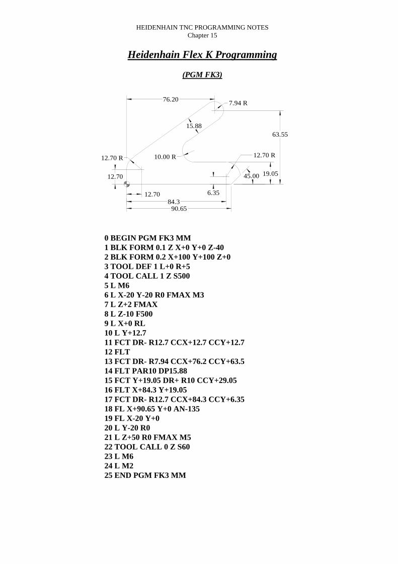
HEIDENHAIN TNC PROGRAMMING NOTESChapter 15
Heidenhain Flex K Programming
(PGM FK3)
0 BEGIN PGM FK3 MM1 BLK FORM 0.1 Z X+0 Y+0 Z-402 BLK FORM 0.2 X+100 Y+100 Z+03 TOOL DEF 1 L+0 R+54 TOOL CALL 1 Z S5005 L M66 L X-20 Y-20 R0 FMAX M37 L Z+2 FMAX8 L Z-10 F5009 L X+0 RL10 L Y+12.711 FCT DR- R12.7 CCX+12.7 CCY+12.712 FLT13 FCT DR- R7.94 CCX+76.2 CCY+63.514 FLT PAR10 DP15.8815 FCT Y+19.05 DR+ R10 CCY+29.0516 FLT X+84.3 Y+19.0517 FCT DR- R12.7 CCX+84.3 CCY+6.3518 FL X+90.65 Y+0 AN-13519 FL X-20 Y+020 L Y-20 R021 L Z+50 R0 FMAX M522 TOOL CALL 0 Z S6023 L M624 L M225 END PGM FK3 MM
12.7084.3
90.65
6.35
12.70 R
12.70
76.20
63.55
10.00 R
19.05
12.70 R
7.94 R
15.88
45.00

HEIDENHAIN TNC PROGRAMMING NOTESChapter 15
Heidenhain Flex K Programming
(PGM FK3 Converted)
0 BEGIN PGM FK3 MM1 BLK FORM 0.1 Z X+0 Y+0 Z-402 BLK FORM 0.2 X+100 Y+100 Z+03 TOOL DEF 1 L+0 R+54 TOOL CALL 1 Z S5005 L M66 L X-20 Y-20 R0 FMAX M37 L Z+2 FMAX8 L Z-10 F5009 L X+0 RL10 L Y+12.711 CC X+12.7 Y+12.712 C X+5.361 Y+23.064 DR-13 L X+71.611 Y+69.9814 CC X+76.2 Y+63.515 C X+80.789 Y+57.02 DR-16 L X+52.815 Y+37.21117 CC X+58.595 Y+29.0518 C X+58.595 Y+19.05 DR+19 L X+84.3 Y+19.0520 CC X+84.3 Y+6.3521 C X+97 Y+6.35 DR-22 L X+90.65 Y+023 L X-2024 L Y-20 R025 L Z+50 R0 FMAX M526 TOOL CALL 0 Z S6027 L M628 L M229 END PGM FK3 MM
12.7084.3
90.65
6.35
12.70 R
12.70
76.20
63.55
10.00 R
19.05
12.70 R
7.94 R
15.88
45.00