to - defense technical information center · document service center knott building, dayton, ......
TRANSCRIPT
UNCLASSIFIED
AD NUMBER
AD093135
NEW LIMITATION CHANGE
TOApproved for public release, distributionunlimited
FROMDistribution authorized to U.S. Gov't.agencies and their contractors;Administrative/Operational Use; DEC 1955.Other requests shall be referred to WrightAir Development Center, Wright-PattersonAFB, OH 45433.
AUTHORITY
AMRL ltr dtd 1 May 1987
THIS PAGE IS UNCLASSIFIED

UNCLASSIFIEDS ED
armed Servicei echnica nonml ion gencyReproduced by
DOCUMENT SERVICE CENTERKNOTT BUILDING, DAYTON, 2, OHIO
This document is the property of the United States Government. It is furnished for the du-ration of the contract and shall be returned when no longer required, or upon recall by ASTIAto the following address: Armed Services Technical Information Agency,Document Service Center, Knott Building, Dayton 2, Ohio.
NOTICE: WHEN GOVERNMENT OR OTHER DRAWINGS, SPECIFICATIONS OR OTHER DATA
IdUTD FOR ANY PURPOSE OTHER THAN IN CONNECTION WITH A DEFINITELY RELATED
GOVERNMENT PROCUREMENT OPERATION, THE U. S. GOVERNMENT THEREBY INCURSNO RESPONSIBILITY, NOR ANY OBLIGATION WHATSOEVER; AND THE FACT THAT THEGOVERNMENT MAY HAVE FORMULATED, FURNISHED, OR IN ANY WAY SUPPLIED THESAID DRAWINGS, SPECIFICATIONS, OR OTHER DATA IS NOT TO BE REGARDED BYIMPLICATION OR OTHERWISE AS IN ANY MANNER LICENSING THE HOLDER OR ANY OTHERPERSON OR CORPORATION, OR CONVEYING ANY RIGHTS OR PERMISSION TO MANUFACTURE,USE OR SELL ANY PATENTED INVENTION THAT MAY IN ANY WAY BE RELATED THERETO.
U NCLASSIFlED

WADC TECHNICAL REPORT 55-355
MINIMUM ALLOWABLE DIMENSIONS FOR CONTROLSMOUNTED ON CONCENTRIC SHAFTS
JAMES V BRADLEY
NoIBMAN F STUMP
AERO MEDICAL LABORATORY
DECEMBER 1955
WRIGHT AIR DEVELOPMENT CENTER

WVAIC TEChTNICAL 1ilPORT 554:35
MINIMUM ALLOWABLE DIMENSIONS FOR CONTROLSMOUNTED ON CONCENTRIC SHAFTS
XVHIGIIT AIRI DI-Al'L OIPM1NT CNE
AIR RE'SENBC1 AND) 1)FA'EIAMENT COMIMAND)
U N ITED STATES AIR FORCE
W~iGh1~ ATTCRS NAIR FORC(E KASFI, 01110

1hia report wa3 prepared by the P"ychology Branch of the Aero MedicalLibordtory, Directorht" of he€earch, Wright Air Ihevelopment Center under aproject idAntifieid by hese;rcl ant Developent ra3k No. 71514 "Control Designanti A.flnunt." Th, rj.eirch proer:u w:ts begun with Norman E. Stump actingI a:k Ocjtntist. Latt,r, Mr. Lt1=p accepted employment with private industry,tarning the revearch program over to James V. Bracley. The research effortw ... kret.ly facilitated by frequwnt consultation with the followine membersof the Controls section of the F-ycholog.y Branch: John ,. Senders (el-.-ctroniccirzuitry], 'A. Dean Ofhiies kstatistics) and John P, 1orn4eth (general eAperi-
The e~qvriaentL:d ati were collected at Antioch College under Contract,o. AF 3A(uuu)-%u u'iuer thoi airection of Dr. Vir rinia L. Senaer3. The authorsare inaebte to Dr. ocnaers for h critical review of the first draft of therer tr An nAny e~cellent suggestion which inproved the final form of thero.prt. i'ht.y ire indebted to the entire fumn Fnrlneering staff" at AntiochOolleg' for n i .ii.. reentltion of data, particulurly to to Alan Lapiner(gr..phi) iaa Gorle Norris kalyi of variance).
>./AD TR 55-355
ABSTRACT
A series of experiments was perforiei to uvtermint the minimum allowabledimensions of circular, nondetent knobs mounted upon concentric bhafts whenfrequent inadvertent operation of aujacent coaial knobs cannot b, tolerated.Both unhielued knobs an" knob who'se front face were jih lded against inad-vertent operation were invuetigated. A btandaru setting wa,4 ued, and measureswere taken of reach time, turning time and inadvertcnt touching of adjacentcoaxial knobs. Manipulated variablos were thlcknes-.o, i&:ater and differencein diameter between the operated knob anc tho aujacent knobs.
The conclusion was reached Lhht if three -nobs arc. to be concentricallyganged, and if the amiddle knob is about 2 in. in diawter (1) the uiazeter ofthe front knob should be at least 1 in. smaller, anU that of the back knob 1 1/4in. greater, than that of the middle knob, k2) the front and middle knobs shouldboth be 3/4 in. thick but the back knob may be as thin as 1/4 in. ATese state-ments apply to both unshielded and shimIded knobs. itatistically significantdecrements in performance between adjacent experimental conditions were foundwhen dimensions smaller than these were used.
Comparisons between the panel space consuea by nong.ngea knobs and byconcentrically ganged knobs indicated that panel op-ce will belaom be saved byconcentrically ganging knob4 when the following conLitions obtain: kl) theknobs can be operated by application of rmoaerate tor.ue, (2) the difference indiAmeter between concentrically mounted kiobs is large enough to insure thattheir inadve'tent operation will be infrequent, (3) s_;ill dimeter k1/2 in. to1 in.) nonganged knobs are acceptable substitutes for the larger diameter con-centrically ganged knobs.
PUBLICATIu.' !Vi rW
This report has been reviewed anu is ipproved.
FOR THE CONDR:
JACK POLLF RDColonel, USAY (YC)Chie_-f, Airco L.t.jlcl LabratoryDirectorate of Reearch
WADC TR 55-355 ii

TABLE OF CONTENTS
' A P P / ;W K ~t A N U W CO E D U R E . . . , . . , . . . , , . . . , . ... .. . , . 3
PI O DY u s o .. . .. .Re u t . . . . . . . . . . .. , . , . . . . . . . . .
CoISnlsions. , ftff tt.......ff.. ....... 12...... ,....... ,,....... 13
EXPERIME NT I-B..,,* ....... .t.... 13t. ......... f...... f .f.f .. ,ff.... f 3
E CPE f Q II-A,...,...,....... .,. ...,.....,..,.............. 15
EXPSHIMENT II-BA.... . f t tt.....f ,. . ,, , ,.ft .. •• ., , • 17ft
EXPERIMENT III-A .. t f....f..,, f,,.,, f., ft,.,f ,,f ,,f ,,,,..,,,,,f, 19
C bIlENT III-B..,....... . , . . ,..,.,,,,.. ....... ... .. , ... 2.2
Conclusions. ft.. tf tf tf tf tf tf f tf tf tf tf tf tf t.. .,,ft.ft.ft.ft.ftft .ft.ft.f.,ft..t.ft .... ft.. ...ft ,.. 24EXPERIMENT IV ......tft., .. ,.,. ,.., .. ... ................ 23
E X P E R I M E N V . . . . . . . . . . . . , . . , .... . . . . . .. ... . . . • . . • . . . . . , . 4
Conclusions ., . .o. . . . . , , . . ., . ,. . , .......... , 26
SUMMARY OF RESULTS..,.,,....... .,,,,. •, .•. ,,, ,•., • t •• • • • 27
GENERAL DISCUSSION. .. .,fffft ,. ........ f • • • • •, f • ft f • • f ft ft • f f • f f f 31
BIBLIOGRAPHY. . ..t... . f.. . . . . . ftt.t t.t ft.. ft•t • ft•t•f.. ft ft•f .. f • • • f 34
WAD -335
WADO TR 55-355 iv
LIST OF TABLES
I Apparatus and eroceaure Variations for Each of the heparate
IT Results of StatistIc4 Analysis for Pilot . 8
III Error Results for kilot Study .............................. 10
IV Statistical Analysis for Experiment I-A.....1.... ........... 3
V Statistical Analysis for Ex periment I-B... ........ ,...... 14
VI Statistical Analysis for Experiment Il-A ............ ,.....,, 15
VII Statistical Analysis for Experiment II-B..................... 17
VIII Statistical Analysis for Experiment III-A ................... 19
IX Statistical Analysis for Experiment III-B............,........ 21
X Statistical Analysis for Experiment I.. ............. 24
I Statistical Analysis for ExperimentV........................... 26
XII Summary Table of Results............. ....................... 28
XIII Frequency of Inadvertent Touching of Ajacent Knobs When theFront, Middle or Back Knob of Three Concentrically Mounted KnobsIs Operated............ ......4 . .. ... .. 9 • •........ .. 30
XIV Panel Area (Times 64/n ) Required for a Given Number of KnobsWhen They Are Concentrically Ganged Versus That Required WhenThey Are Completely Isolated from Each Other (Diameter of FrontGanged Knob: 1/2 Inch) .... 99.4.. ......... ,...,..9 ......... 31
LIST OF ILLUSTRATIONS
Flaure Page
1 Concentrically ganged knobs................................ • .
2 Hazard of inadvertent operation of adjacent knobs... ......... 3 1
3 Disadvantage of shielding knobs when shield is attached to thechassis. T **55-355* .,.,,....,0....,,,..,,...,.,,,..., 2
WADC 'T 55-355 V

LIST OF ILLUSTRATIONS (CONT'D)
4 Disadvantage of shielding knobs when shield is attached to theknob Shaft2 ,,.,.,....9,.9.9.. 999.. 9999., 9999.. .... ,.. 2
5 Apparatus.**............99 .....................,...,.....o....... 4
b Specific task conditions for pilot st7......................... 7
7 Error scores for the operation of the middle knob of a series ofunshielded, concentrically mounted knobs when thickness, diameterdifference and diameter of the operated knob are varied. .,..... 9
8 Specific task conditions for Experiment I-A..................,. 12
9 Results for Experiment I-A..... £. .... 99.9.9.....9... ........ 12
10 Specific task conditions and results for Experiment I-B.......... 14
11 Specific task conditions and results for Experiment II-A....... 16
12 Results for Experiment II-B............... ....................... 18
13 Specific task concitions for Experiment II-Bi.......,....., 18
14 Specific task conditions and results for Experiment III-A........ 20
15 Resalts for Experiment III-B................. 22
16 Specific task conlitions for Experiment III-B...................0 22
17 6pecific task conaitions for Experiment IV..................... 23
18 Results for Experiment IV 23
19 Specific task conditions and results for Experiment V............ 25
20 Minimum allowable dimensions for either shielded or unshieldedknobs when (a) knobs can be operated by application of moderatetorque, (b) frequent inadvertent operation of adjacent controlscannot be tolerated, (c) diameter of the middle knob is between1 1/2 and 2 1/2 inches......... ...... ... ,*......... ...... ..... 29
21 Number of separated knobs of various diameters which can beplaced 1 in. apart in the same panel area as is required forthree concentrically ganged knobs. Example 4 is a limiting case.The combination of diameters shown for the concentrically gangedknobs was not specifically investigated. It is probably thesmallest set of concentrically ganged knobs whose use is implic-itly acceptable on the basis of these expriments............... 32
WADC TR 55-355 vi
INTHODUC TION
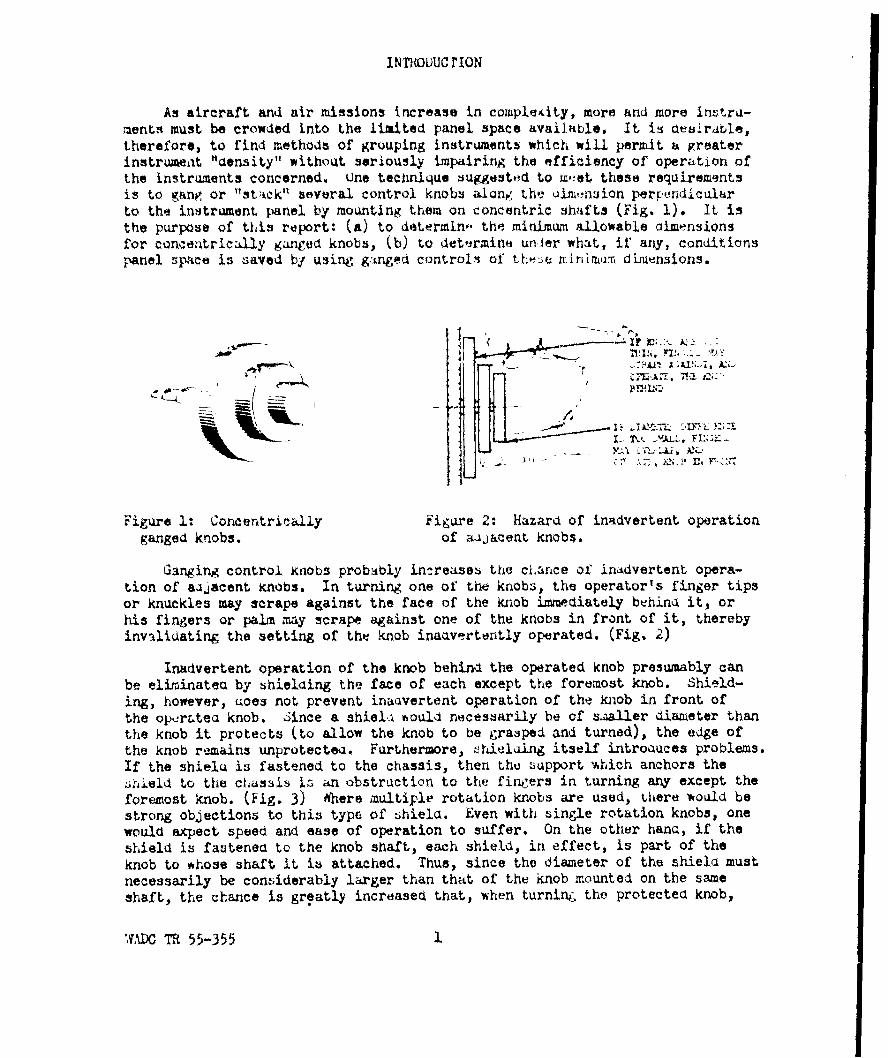
As aircraft and air missions increase in complekity, more and more in.tru-ments must be crowded into the limited panel space available. It is desirable,therefore, to find methods of grouping instruments which will permit a greaterinstrument "density" without seriously impairing the efficiency of operation ofthe instruments concerned. tne technique suggestod to w',et these requirementsis to gang or "stack" several control knobs alone the uim,-naion perpendicularto the instrument panel by mounting them on concentric shafts (Fig. 1). It isthe purpose of this report: (a) to determin- the minimum allowable dimensionsfor concentrically ganged knobs, (b) to determino unler what, if any, conditionspanel npace is saved by using gitnged controls of these zrtimirr, dimensions.
Figure 1: Concentrically Figure 2: Hazard of inadvertent operation
ganged knobs, of aujacent knobs.
Ganging control knobs probably in,:reases the clkance of inadvertent opera-
tion of aujacent Knobs. In turning one of the knobs, the operator's finger tipsor knuckles may scrape against the face of the knob immediately behina it, or
his fingers or palm may scrape against one of the knobs in front of it, thereby
invalidating the setting of the knob inaavertently operated. (Fig, 2)
Inadvertent operation of the knob behinri the operated knob presumably can
be eliminates by shielding the face of each except the foremost knob. Shield-
ing, however, aoes not prevent inauvertent operation of the knob in front of
the opejr&tea knob. jince a shieli *ould necessarily be of s&aller diameter than
the knob it protects (to allow the knob to be grasped and turned), the edge of
the knob remains unprotectea. Furthermore, hielaing itself introauces problems.
If the shielu is fastened to the chassis, then the support which anchors the
tileld to the chassis is an obstruction to the fingers in turning any except the
foremost knob. (Fig. 3) Where multiple rotation knobs are used, 0here would be
strong objections to this type of :hiela. Even with single rotation knobs, one
would expect speed and ease of operation to suffer. On the other hans, if the
shield is fastened to the knob shaft, each shield, in effect, is part of the
knob to whose shaft it is attached. Thus, since the diameter of the shield must
necessarily be considerably larger than that of the knob mounted on the same
shaft, the chance is greatly increased that, when turnin, the protected knob,
',D TR 55-355 1

4
the operator's fingers will overlap the shield and thereby inadvertently turnthe knob to whiich it is attached. (Fig. 4). Finally, there is a method ofshielaing which wola be free from the objections listed above, but which, inall probability, woulQ be unacceptable to design engineers because it wouldnearly double the number of concentric shafts required for a given number of6angea knobs. This would ba to fasten the shields to fixed concentric shaftsY"shield" shafts alternatini with "knob" shafts) which would not rotate andwhose sole purpo.;e would be to hnchor the shields.
LK
~P ~AN) TU 'f( ILlZ k20 TC
WAA \HM ITL rTC
Tt13ii wLti;
iieure 3: isadvantage of shielding Figure 4: Lisa"vantage of shieldingknobs when shield is attached to knobs when shield is attached tothe chassis, the kiob shaft.
In the series of experiments to be reported here, the situations in whichan operator makes settings with either the front, the riuale or the back knobof three concentrically ganged knobs were sL.ulatea or reproduced. Because thechance of inadvertent operation is inferred from the frequency of inadvertenttouching, the results will apply 2 to a series of concentrically ganged knobs
all of which are cap;,ble of being operated by the application of moderate tor-que. Specifically, the results will not apply to concentrically ganged detent
knobr.
Three variables associated with knob dimensions were investigated: thick-ness, cdaimeter ana uifference in diameter between the operated Knob anQ thea"Jacunt knobs. De ign engineur aay set thu.ir own criteria for minimum allow-able uimensionb. The authors took as minimum allowable dimension the largestvalue testea at which performance was significantly superior to performance atthe next smaller value. This was usually the point at which the time or errorcurve became nearly parallel to the A-axis. Another perfectly reasonable cri-terion woula be dimensions which give rise to an arbitrarily selected percentageof errors, such as errors on 5% of all trials. Designers %ishing to use such acriterion will find the necessary figures in the Appenix. Obviously such an
M"wC R 55-355 2

approach can be expected to rvi.dut in an entirely different set of "minimumallowable dimensionn;."t
APPARATU A?;) kROO:tUWL
The subject's task was to reach from a fL~ed poition, grasp one of threeganged controls and make a ztwoarc setting. Then the re ults were to apply tounshielded controls, le w.s instructed to avuil, touching Y of the other knobsin the series. ',hen :shielaed control were to be sitiul.ted, he was inzstructedonly to avoiu touching the knobs in front of the operated knob (since 4hielaingprotects the knobs behind the operated knob but not those in front of it). Ineither case he was instructed to regard the controls to be avoided as being setto an extremely delicate adjustment, the accuracy of which was just as importantas that of the adjustaent he was to make with the operated control. He was fur-ther instructed to consider that the blighteut touch of the hanu would invalidatethe setting of a control inadvert.ntly touched. With this orientation he wasinstructed to work both for speed ana for accuracy as defined by abbence of inad-vertent touching of the "prohibited" controls. Inadvertent touching, rather thaninadvertent operation, of t "wrong" control was selected a the criterion oferror because frequency of inadvertent operation woulu necessarily be a functionof the amount of torque required to move the inadvertently operated knob. It isnot intended that frequencies of inadvertent touching be interpreteu as absolutefrequencies of inauvertent operation. It is intended only that they serve as anindex of relative "task ;ifxiculty" or "error susceptibility" in comparing oneexperiental coniltion .ith another. 1inally, the iubject was askea always tograsp the operated control with the thuab A ia1,trically cppoite the finglers andin contact ith the knob.
The apparatus is shown in Figure 5. rhe c ieuence of o >.rations was asfollows. At the start of a trial the oporateu knob ws in either its extremecounterclockwise or its extreau clockwise poition (i.e. with the black rcacialline on its face pointing at 8 o'lock or at 4 o'clock), anx the sutject wasdepressing the telugraph key vith hii uo inint Lian. The e"perimenter thenthrew a switch to illwminate the iiber light. Thia wau. a -ignal to the ubjectthat, whenever he was ready, he :i.ht reach up, avoiaing the "pronibited" knobs,grasp the "operated" knob ana turn it until the black rauial line on its facew.s pointing straight up, at *khich point the lijht woult go out. .'hen he hadturned out the light, the subject was to return h riancn to the ttl-;graph keyuntil the experimenter threw a 3witch uisco-mectin#_ hiL tLe, clocks from thesubject's apparatus. The throwing of the s~itcb was a i~'naJ to the subject toreset the operated knob. lie was to alternate the startini position of the ,lackracial line between its extreae clockwise an itL extrtu counterclockwise posi-tions. There were five clockwise an_ five coutiterclockise settings for eachexferinental condition.
The experinenter's apparatus recoraed: (a) reach time - the time elapsedfrcm the release of the telfgraph key until the operated knob begins to turn,(b) turning time - the tize, after the operated knob startb to turn, that theknob bpenas outslue of the narrow "adjustment" zone in which the black radialline on its face is vertical dnu the amber light is extinguished, (c) back knob
*I'AX TR 55-355 3

jig*~
10LA
WAX TA55-35
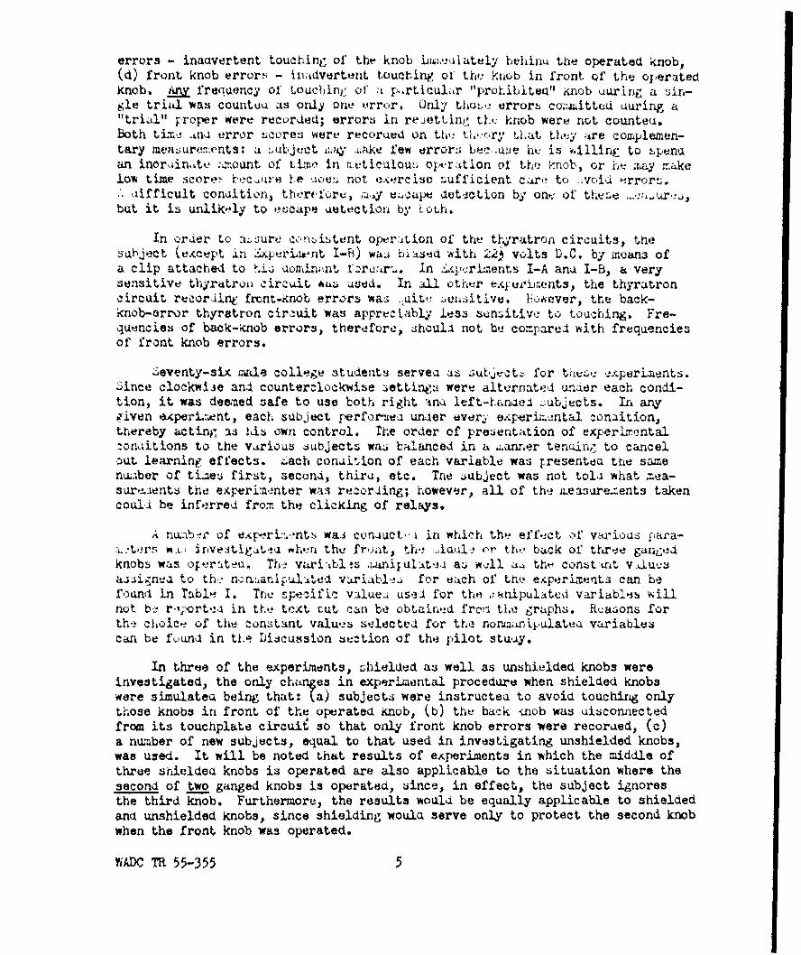
errors - inadvertent touching of tht- knob bioi.e.-iately behinu the operated knob,(d) front knob error- - in.tdvertent toucting of th. ?nob in front of the operatedknob, mv frequency of touchin: of' k p,rticulr "prohibiteu" knob uuring a sin-gle trial was counteu as only one "rror. Only tho e trror. co.4hittcd uuring a"trial" proper were recorded; errors in rejettimn t.#j knob were not counteu.both tmc ana error sicores were recorded on th'! thi':cry Uat thly are complemen-tary mea:uren.ents: a _ubjuct iy i"ake few error i bec.u3e hv is vliinr to :punaan inoriin,tv :%ount of tLtn in r,,ticuloun opuration of' the knob, or he. ;ry r.4kelow time score bcc~u s .heioes not eercisc sufficient care to I voii -rrorz.,, aifficult conaition, thereforv, ziy v cap detct.lon by on.. of thene ,but it is unlik-ly to eocape uetection by LoLh.
In order to aLure conAstent oper,-tion of the t- rtron circuits, thesUbject (exacept in Iperiu*int 1-B) wai biased with 22, volts D.C. by means ofa clip attached to aia omin4uit. rcr-.., In qcrlrnents I-A ana I-B, a verysensitive thyratro4 circuit *4a used. In all otir expurirents, the thyratroncircuit recordint front.-knob errors wa ,uit, :ensitive. bowever, the back-knob-error thyratron circ-uit was appreciably less sunAtiwv to touching. Fre-quencies of back-knob errors, therfore, shoull not be compared with frequenciesof front knob errors.
Seventy-six "ale college students servea as :ubjtctz for t .-,: *xperients.Ance clockwije and counterclockwise 3ettings were alternated unzier each condi-tion, it was deemed safe to use both right inQ left-hanael .:ubjects. In, anyi'iven experient, each subject performea unuer ever3 e.perin.cntal condition,thereby acting as Uti own control. The order of presentation of experizentalzoniitions to the various subJects was balanced in a Lanner ten.in, to cancelout learning effects. Z.ach conuition of each variable was rresentea the samenu;iber of ti2e* first, 3econl, thiru, etc. The subject was not tola what M.ea-sure ients the experimenter was recording; however, all of the neasure.-ents takencouli be inferred from the clicking of relays.
A nubir of e~p-rL:.'nt. was coniuct," in which the effect of various fara-:.,:ters wt irivestigateu ,h! r the froat, th,! ,iul • ,r thy' back of tre gangedknobs was oFerateu. Th vari:bls ,ianiiulat.-,i as wll a,4 tht- const-nrit. v.luusa.signva to th. n :,anil'±te- variabl, for each of the experiments can befound in Tabl-- I. The cific value-i used for the ihanipul~ted variables willnot be r.4;ortea in the text tut can be obtained frc,'" the graphs. Reasons forth choice of the constant values selected for the noaanipulatea variablescan be found in the Discussion section of the pilot stuy.
In three of the experiments, Lhielded as well as unshielded knobs wereinvestigated, the only changes in experimental procedure when shielded knobswere simulated being that: (a) subjects were instructea to avoid touching only
those knobs in front of the operated knob, (b) the back -nob was uisconnectedfrom its touchplate circuie so that only front knob errors were recorued, (c)a number of new subjects, equal to that used in investigating unshielded knobs,was used. It will be noted that results of ehperiments in which the middle ofthree shielded knobs is operated are also applicable to the 6ituation where thesecond of two ganged knobs is operated, since, in effect, the subject ignoresthe third knob. Furthermore, the results would be equally applicable to shieldedand unshielded knobs, since shielding would serve only to protect the second knobwhen the front knob was operated.
WADC TR 55-355 5

cl ' -- :.
' ~ ~ 4 A . t A 0 ~Iti A' t a 1ci 4 * % II C I 0
1- 5 0 j 0 4) A3 40 Cl 44 a ~ )~ _
* ~*- 45- ~ X. nA Is. A2*. 4-. .
ol .0 INaa0
o .0 1.' .4. . d 4
-0 0 qS- D -4 ZZ) - 4 )-
o~~ 44 Cl
.4U -0 1
* 0 T5 rl 2i A 0 0
Qa ci 00 00
A.. A O'o
V V
*0 430'15
,4 A4 '.
sAJC .125-3 5

There were occAsional variations in the general apparatus anu proceduredescribedi above. In &periment I-A, errors were recorded, not. by a lig;ht onthe experimenter's panel, but by a Veeder counter which operated every time theback knob was touched during a trial (an error, however, was still defined asone or more inadvertent touchings in a single trial), The operation of thecounter was far noisier than that of the holding relay used in the succeedingexperiments, and the association between its operation and the commission of anerror was far more compelling than was the association between errors and relayclicks in the experiments which followed. In !xperim-:nt I-B, the subject wasgiven no instructions whatever concerning the avoidance or nonavoidance ofadjacent knobs. The "back Knob" was a 9 in. uiar.eter m,tal plate, fastened tothe chassis by four screws. In Ji*perimtnt IV, the subject operated the backknob and a single touchplate circuit was used to record inadvertent touching ofeither the front or middle knob. i'nerefore it was impossible to determine whichknob ha been the cause of the error. In Experiment 7, the subject made set-tings with his eyes closea, anq reset the kiiob with his !.yet open. The overheadlights were extineuished and the subject "observed" tk# wiuber light through hisclosed eyelids, using the associated relay clicks as supplentntery cues. Thesubjects used for this experiment were the same subjects who had been used inExp-rijent IV. They were run Lm=eociately after the completion of ExperimentIV with no interval between experiments other than that necessary to read a newset of instructions. The reason for this procedure was to provide the subjectswith a foreperiod of practice (Experiment IV) in which to learn the location ofthe operated knob and acquire a kinaesthetic "fool" for the task.
PIWT &TUJY
rhis experient was an explora-tory one. It waz intenaed that itsresults should indicate the properdirection for more precise and spe- /c2fic experiments.
The task required was theoperation of the middle knob of Xtnree, unshielded, concentrically A.
mounted knobs. This was presumedto be the iost aifficult taskencountered in the operation ofthree cvncentrically mounted knobs.It was selected for investigationon the assumption that a variablefc"iri to be weak or in.>i_,nificantin this ituation would probably jX&c'4 ,be negligible in all others. It A:'AY:X, .was hoped in this fashion to reduce F Al:-'the number of variables requiring 'investigation in the experimentsto follow.
Figure 6: 6pecific task conditions forpilot study.
WI.C TR 55-355 7

The diameter of the operated knob, the ilameter uifference between theoperoted knob and both the front knob and the back knob, and the thickness ofall three knobs wore varied. In any given experimental condition, all threeknobs had the same thickness, and the same value was used for both diameterdifferences. There were four conditions of each variable, uiking 64 possiblecombinations. rsch of these combinations was tested. The experimental designis described by Lindquist (3). Each subject performed under one fourth of thepossible conditions in such a way that each subject performed uxroer all twovariable combinations but under only one fourth of the possible three variablecombinations.
TABLK II
Results of atistical Analy3is for Pilot .tcuay
si;nificance Levels from Analysis of Variance
Diameter TxI x.DType of Leasure Thickness £ifference Uiameter x.__ W xi (.ithin Groups)
oack itnob Errors .001 .001 NS .001 NS NZS .001
Front Knob irrors .W01 .01 .001 .001 N3 .01 .001
heach Time .W01 .001 .01 14S NS .01 .001
lurning rime .001 .001 .001 N5 .01 .001 .001
.jiscussion of nesults: r-3cause the experiment was intended only as a;uiue for further research, only those results which strongly influenced theiir!ction taken in rubseju-ent experiments All be disicussed, the discussionbeing basea :olely upon the traphs and t.e analysis of variance for errors.
iDiameter, as a .ain effect, influencea only front knob errors. Its only.ignificant interaction was oith uiameter oifference for front Knob errors.For both error -eaiurerents, thicknesL anA Qiaaeter difference were nighly sig-nificant, both as main effects and in interaction with each other. Diameter,then, is by, far the weakest ana leajt important variable of the three. Anexamination of the graphic data suggests that, when uimreter had a 5ignificanteffect, tht sig-nificance was probably aue to the 3 and 4 inch uiameter values,were perfor nce wa poor, rather than to the 1 or 2 inch values. In most ofthe exp-erirents to iollow, thereforo, th,! uiar,eter of the operated knob washel, constant at 2 in. since this iture seemj tu be about the optimum, sincesmall chfnges in uiameter arounu 2 inches apparently have little elfect uponperforance, an, Aice 2 inches reraits reasonable values for front and backknob aiameters when a uiameter uifference is usea which the graphic data seemto de;hand (i.e. about 14 in.).
; TA' l 55-355 8

F*004Y X
sGo
Ito.0
i t) 6
S PI Sl
t t
k- 5
30
I1O&-. K.
2i 3
I- k 4I 0 I_. I
Figure 7: Error cores f'or the opraion of the nddl~e kob of a eriesof unshielded, concentrically mounted kobL whn thicknvs, diameter
difference and diameter of the operated knb are varied.
Errors continue to aiminish rapiu!ly ith increasing, diameter diffv'rne upto the end of its range of values. One inch, then, is not a sufficiently large
difference in diameter to reduce errorb to a tolerable level. Therefore,, in the
expriments to follow, the range of diameter ifferences waj e-tended.
Diameter differee appears to have it5 greatst effect upon front knoberrors, although back knob errors are aliso affected. 3Aito back knob errors,
WAD 410 55-35 9~93 1
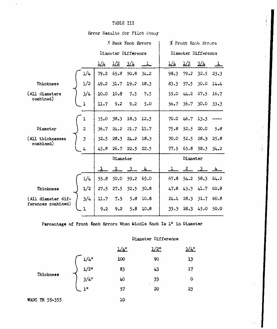
TABLE III
Error Results for Pilot 6tuay
% Back Knob Errors % Front Knob Srr rs
Diameter Difference Diameter Difference
!ZA 12 /A 1 IZA I_
1/4 79.2 65.8 50.8 34.2 98.3 79.2 32.5 23.3
Thickness 1/2 49.2 31.7 19.2 18.3 83.3 57.5 30.0 14.4
(All diameters 3/4 10.0 10.8 7"5 7.5 55.0 44.2 27.5 16.71 11.7 9.2 9.2 5.0 56.7 36.7 30.0 33.3
1 35.0 38.3 18.3 12.5 70.0 46.7 13.3 ----
Diameter 2 36.7 24.2 21.7 11.7 75.8 52.5 20.0 5.8
(All thicknesses 3 32.5 28.3 24.2 18.3 70.0 52.5 28.3 25.8combined)
4 45.8 26.7 22.5 22.5 77.5 65.8 58.3 34.2
Diameter Diameter
1 2 1 2 __ __
1/4 55.8 50.0 59.2 65.0 67.8 54.2 58.3 64.2
Thickness 1/2 27.5 27.5 32.5 30.8 47.8 43.3 41.7 60.8
(All diameter dif- 3/4 11.7 7.5 5.8 10.8 24.4 28.3 31.7 60.8ferences combined)
i 9.2 9.2 5.8 10.8 33.3 28.3 45.0 50.0
Percentage of Front Knob Errors When icdle Knob Is 1" in Diameter
Diameter Difference
1/41' 1/211tLL"
1/4" i.00 90 13
1/2" 83 43 17Thickness
3/4" 40 33 0
i" 57 20 23
WADC TR 55-355 10

diminish with increasing diameter difference (as more back knob area becomesexposed to the hazard of inadvertent touching) it seems obvious that it i notthe diameter difference between the middle and back knob, but rather the dia-meter difference between the middle and front knob, which influences back knoberrors. Presumably, at small diameter differences,the subject, in attemptingto avoid touching the front knob, reaches farther back on the middle knob ingrasping it, thereby increasing the chance of touching the back knob and record-ing a back knob error. If this be true, then back knob errors vary with diameterdifference only because the subject is trying to avoid touching the front knob.In any event the data suggest that the diameter difference between the middleand back knob is an irrelevant variable. In most of the experiments to follow,therefore, the back knob was assigned a large constant diameter, and only thediameter difference between the middle and front knobs was varied.
Since thickness was varied for all three knobs simultaneously, it is impos-sible to say with certainty which knob thickness is responsible for a certaineffect. It seems entirely reasonable to assume, however, that the influence ofthickness upon back knob errors is mainly attributable to the thickness of themiddle knob. The knob whose thickness affects front knob errors is more diffi-cult to identify on logical grounds. One might expect front knob errors toincrease as front knob thickness increases, since this brings the face of thefront knob closer to the palm of the hand. On the other hand, one might expectfront knob errors to increase as middle knob thickness decreases, since subjectsmay grasp the middle knob closer to its face when thickness is small in anattempt to avoid back knob errors. In the present experiment front knob errorsincreased with decreasing thickness. Therefore the evidence supports the secondhypothesis. However, both hypotheses may be true, the second effect beingstronger than, and obscuring, the first when thicknesses are varied simultan-eously. It would be aesirable, then, that these two hypotheses be testedseparately in the experiments to follow.
Table III shows that large diameter differences are necessary even withsmall diameter knobs. '.ilcoxon's nonparametric test for paired replicates (4)was applied to the data for front knob errors when the operated knob diameterwas 1 inch. Statistically significant improvements in performance were foundfor each increase in diameter difference from 1/4 in. to 3/4 in. (at which theerror frequency was 13.3%). Since at a diameter difference of 3/4 in. the frontknob is 1/4 in. in diameter, it is clear that using knobs of small diameter doesnot relieve one of the necessity to use large diameter differences.
VADC TR 55-355 11
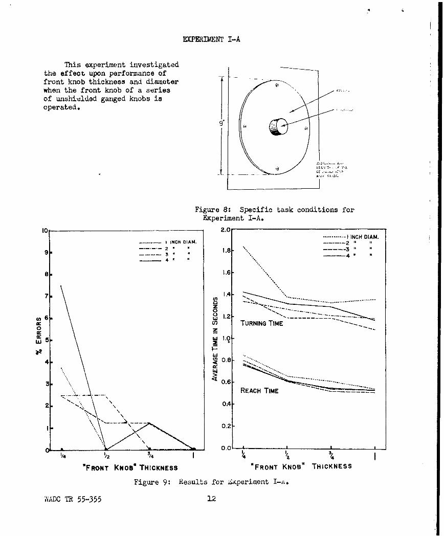
EXPERIMENT I-A
This experiment investigatedthe effect upon performance offront knob thickness and diameterfwhen the front knob of a seriesIof unshiolded ganged knobs isIoperated.
Figure 8: Specific task conditions forExperiment I-A.
10 2.0...... -I INCH DIAM.
S........ I INCH DIAM. ------- 293 34 444 3
8 1.6-
7a IA- 1
1~~~~~.2-U) TURNING TIME
w 5. w1.0-
w4 0.8 -..-.
3w . 0.6- REACH TIME--
22 04-
0.2-
'/ 12 /4 1/ 3/j4
"F RON T KNOB" THICKNESS "FRONT KNOB" THICKNESS
Figure 9: Results for Zxperiment I-i.
-AADC TR 55-355 22
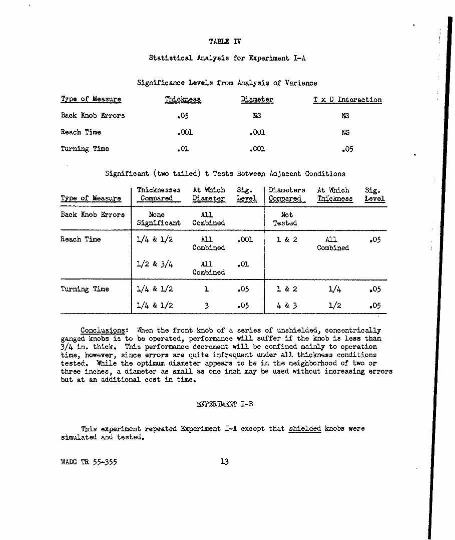
TAMAE IV
Statistical Analysis for Experiment I-A
Significance Levels from Analysis of Variance
Type of Measure Thickness Diameter T x D Interaction
Back Knob Errors .05 NS NS
Reach Time .001 .001 NS
Turning Time .01 .001 .05
Significant (two tailed) t Tests Between Adjacent Conditions
Thicknesses At Which Sig. Diameters At Which Sig.Type of Measure Compared Diameter Level Cormared Thickness Level
Back Knob Errors None All NotSignificant Combined Tested
Reach Time 1/4 & 1/2 All .001 1 & 2 All .05Combined Combined
1/2 & 3/4 All .01
Combined
Turning Time 1/4 & 1/2 1 .05 1 & 2 1/4 .05
1/4 & 1/2 3 .05 4 & 3 1/2 .05
Conclusions: When the front knob of a series of unshielded, concentricallyganged knobs is to be operated, performance will suffer if the knob is less than3/4 in. thick. This performance decrement will be confined mainly to operationtime, however, since errors are quite infrequent under all thickness conditionstested. While the optimum diameter appears to be in the neighborhood of two orthree inches, a diameter as small as one inch may be used without increasing errorsbut at an additional cost in time.
EXPERIMENT I-B
This experiment repeated Experiment I-A except that shielded knobs weresimulated and tested.
WADC TR 55-355 13
2.0.......... 4 INCH DIAM.
-- 4 k
1.4 - ... ......,....,.........................
0
9z 1.0 TURNING TIMEw
Z, I 0.4
_ __0 REACH TIME
0.2-
0.01
'FRONT KNOB" THICKNESS
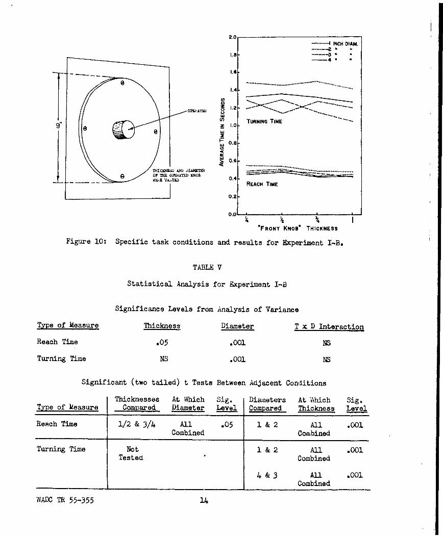
Figure 10: Specific task conditions and results for Experiment I-B.
TABLE V
Statistical Analysis for Experiment I-B
Significance Levels from Analysis of Variance
Type of Measure Thickness Diameter T x D Interaction
Reach Time .05 .001 NS
Turning Time NS .001 NS
Significant (two tailed) t Tests Between Adjacent Conditions
Thicknesses At Which Sig. Diameters At '4hich Sig.Type of Measure Compared Diameter Level Compared Thickness Level
Reach Time 1/2 & 3/4 All .05 1 & 2 All .001Combined Combined
Turning Time Not 1 & 2 All .001Tested Combined
4& 3 All .001Combined
WAO T 55-355 14

4
Conclusions: When the front knob of a series of bhielded concentricallyganged knobs is to be operated, a 1 in. diameter knob is too small for optimalperformance scores. However, since concentric ganging necessarily involves theuse of knobs of several different diameters, a diameter of 1 inch for the frontknob cannot be rejected simply because it is not the optimum.
EXPERIMENT II-A
This experiment investigated the effect of front knob thickness and thediameter difference between the middle and front knob when the middle of three,unshielded, ganged knobs is operated.
TABLE VI
Statistical Analysis for Experiment II-A
Significant (two tailed) tSignificance Levels Tests Between Adjacent
from Analysis of Variance Conditions
Front Knob Diameter T x DD Diam. Diffs. At Which Sig.Type of Measure Thickness Difference Interaction Compared Thickness Level
None AllBack Knob Errors NS .01 NS Significant Combined
AllFront Knob Errors NS .001 NS 1/4 & 1/2 Combined .01
All1/2 & 3/4 Combined .01
AllReach Time NS .001 NS 1/4 & 1/2 Combined .05
All1/2 & 3/4 Combined .001
AllTurning Time NS .01 %, 1/4 & 1/2 Combined .05
All1/2 & 3/4 Combined .01
WADC TR 55-355 15

50 - -.... . I00.. . NCNT KNOB THICK FRONT KNOBB'/,t THICK
45 NY X TH* 90 ." " I
4.0 80
0 35 - TO Io0'K 30- w 60.
00 0
Z 25. 50.
z20- w 40 ,
M\ L
/ 30.
10./ 20.
5~. 10 K5\f-ft-- -.-. I0~
'/ ' % I %I 1 14 I I I4DIAMETER DIFFERENCE DIAMETER DiFFERENCE
BETWEEN FRONT St MIDDLE KNOBS) (BETWEEN FRONT a MIDDLE KNOBS)
FRONT KNOBIV" THICK
U U 1.5"-. ..I ,
IAAF
E, TRACH TME
I , I ft I
hii
w 1.0-
0.5 *REACH TIME AVOIDED
THICiNESS, OF FRONTKNOB AND DIAMETER~DIFFERENCE BETWEEN
0.0_________________ FRONT AND MIDDLEo/4 ' /4 1I /4 1/2 KNOBS WERE VARIED
DIAMETER DIFFERENCE
(BETWEEN FRONT & MIDDLE KNOBS)
Figure 11: Specific task conditions and results for Experiment II-A.
WADC TR 55-355 16

Conclusions: When the (2 in. aiameter, 1/2 in. thick) middle of threeunshielded, concentrically ganged knobs is to be operated: (a) performance isindependent of the thickness of the front knob (within the range: 1/2 in. to1 in. front knob thickness), (b) performance in general suffers when a diameterdifference of less than 3/4 in. exists between the front and middle knob.
EXPERIMENT II-B
This experiment repeated Experiment II-A except that shielded knobs weresimulated and tested.
TABLE VII
Statistical Analysis for Experiment II-B
Significant (two tailed) tSignificance Levels Tests Between Adjacent
from Analysis of Variance Conditions
Front Knob Diameter T x DD Diam. Diffs. At Which Sig.Type of Measure Thickness Difference Interaction Compared Thickness Level
AllFront Knob Errors NS .001 NS 1/4 & 1/2 Combined .01
All
1/2 & 3/4 Combined .05
All1 & 1 1/4 Combined .05
AllReach Time NS .001 NS 3/4 & 1 Combined .05
None AllTurning Time NS .01 NS Significant Combined
WADOC TR 55-355 17

100FRONT KNOIDiVTHICK FRONT KNOB'aV THICK
90 """ I\ \.
so- 2.0
=: O %,.o co) TURNING TIME
cc 40\0 1.0
30 \-.
210.-REACH TIME '
20 -\ -- I 0.0
DIAMETER DIFFERENCE DIAMETER DIFFERENCE
(3ETWEEN FRONT a MIDDLE KNOBS) ( BETWEEN FRONT IN MIDDLE KNOBS)
Figure 12: Results for Experiment II-B.
Conclusions: When the (2 in. diam-
eter, V2 im. thck) middle of three,11 shielded concentrically ganged knobs is
Kr- 7~7~N:to be operated: (a) performance isLI independent of the thickness of thefront knob (within the range: 1/2 in.to 1 in. front knob thickness), (b)performance suffers when a differenceof diameter of less than 1 1/4 in.
I exists between the front and middleAk. knob.
Figure 13: Specific task conditions
for Experiment IU-B.
WADC TR 55-355 18

MPERIMENT III-A
This experiment investigated the effect of middle knob thickness, anddiwacter difference between the middle and front knob, when the middle of three,unshielded, concentrically ganged knobs is operated. One of the "thicknesses"investigated was a 1/2 in. thick knob separated by a 1/2 in. space gap from theface of the knob behind it, so that the distance between middle knob face andback knob face was one inch.
TABLE VIII
Statistical Analysis for Experiment I1-A
Significance Levels from Analysis of Variance
Type of Measure Middle Knob Thickness Diameter Difference T x DD Interaction
Back Knob Errors .001 .05 .05
Front Knob Errors .001 .001 .001
Reach Time .001 .001 NS
Turning Time NS .001 .05
Significant (two tailed) t Tests Between Adjacent Conditions
Thicknesses At Which Sig. Diam. Diff. At Which Sig.Type of Measure Compared Diam. Diff. Level Compared Thickness Level
NoneBack Knob Errors 1/2 & 3/4 1/2 .05 Significant
1/2 & 1/2spaced 1/2 1/2 .01
1/2 & 1/2
spaced 1/2 1 1/4 .05
Front Knob Errors 1/2 & 3/4 1/2 .05 1/2 & 3/4 1/2 .01
1/2 & 3/4 3/4 .01 1/2 & 3/4 3/4 .001
1/2 & 3/4 1 .05 1/2 & 3/4 1 .05
1/2 & 1/2spaced 1/2 1/2 .001 3/4 & 1 1/2 .05
1 & 1 1/4 1/2 .001
All AllReach Time 1/2 & 3/4 Combined .01 1/2 & 3/4 Combined .001
1/2 & 1/2 All Allspaced 1/2 Combined .001 3/4 & 1 Combined .001
Turning Time Not Tested 1/2 & 3/4 3/4 .01
1/2 & 3/4 1 .001
1,_ 11/4 1/2 .05
WADC TR 55-355 19

100
MIDDLE KNO O"THICK . MIDDLE KNOE/THICK
90 -
W SIACE'- QAP WITH Y IN SPACE-AP
so-
IK0
Co \Go.T
o Wz \ \
10 040 N
30-
N 20.,-.. \ -
10
DIAMETER DIFFERENCE DIAMETER DIFFERENCE
(BETWEEN FRONT a MIDDLE KNOBS) (BETWEEN FRONT a MIDDLE KNOBS)
2.0
-- MIDDLE KNOB'/,'THICK
L. --- In
WITHf III, SPACE-GAP
01
z -
Ct) 1.2 '- - -
1,0 TURNING TIME
l-
> 0.6
04 REACH TIME AOD
o,2 AVOIDED
oI },/4 MIDDLE KNOB TH1ICMSAND DIAMETER DIFFERENCE
DIAMETER DIFFERENCEBETWEEN FRONT a MIDDLE KNOBS) BETWN FRONT AND MDDLE
KNOBS WERE VARIED
Figure 14: Specific task conditions and results for Eiperiment Ill-A.
Conclusions: When the (2 in. diameter) middle of three, unshielded, con-
centrically ganged knobs is to be operated: (a) performance improves with
increasing middle knob thickness up to a thickness of 3/4 in., (b) under certain
conditions, spacing between middle and back knobs is equivalent to and inter-
changeable with middle knob thickness (because perforaiance with the 1/2 in. thick
WADC TR 55-355 20

middle knob separated by a 1/2 in. space gap from the back knob was statisti-cally indistinguishable from performance with a 1 in. thick middle knob withno space gap, but was frequently superior to performance with a 1/2 in. thickmiddle knob with no space gap), (c) performance improves with increasing diam-eter difference between front and middle knobs up to a diameter difference of1 in. for performance in general and up to 1 1/4 in. in certain cases.
EXPERIMENT III-B
This experiment repeated Experiment III-A except that shielded knobs weresimulated and tested.
TABLE IX
Statistical Analysis for Experiment III-B
Significance Levels from Analysis of Variance
Type of Measure Middle Knob Thickness Diameter Difference T x DD Interaction
Front Knob Errors NS .001 .05
Reach Time .01 .001 NS
Turning Time NS .05 1S
Significant (two tailed) t Tests Between Adjacent Conaitions
Thicknesses At Which Sig. Diam. Diffs. At Which Sig.Type of Measure Compared Diam. Diff. Level Compared Thickness Level
Front Knob Errors Not Tested 1/2 & 3/4 1/2 .05
1/2 & 3/4 3/4 .001
1/2 & 3/4 1 .05
1/21/2 & 3/4 spaced .001
1/2
3/4 & 1 1/2 .01
3/4 & 1 3/4 .05
All AllReach Tije 1/2 & 3/4 Combined .05 1/2 & 3/4 Combined .001
1/2 & 1/2 Allspaced 1/2 Combined .01
All
Turning Time Not Tested 1/2 & 3/4 Combined .05
WAO TR 55-355 21

2.0MIDDLE KNOID~i"THICK --- --- MIDDLE KNOB " THICK
MIDDL KNOB~'THI3/4/30 0 .... I * ".8N
,, 4 4 wiTh Vfl I. 3PAC|-gAp
WITH 1, IN. SPACE-GAP WA
\1 .6 "N.
2 5 .A
0, 20 1.2
,, \TURNING TIMEW z
S- 1.00 Wo \\,,
• w 0.8.
0.40.2
0 0.40 RAH IM
1,2 /4 1 I14 1 '44 /DIAMETER DIFFERENCE DIAMETER DIFFERENCE
(BETWEEN FRONT 0 MIDDLE KNOBS) (BETWEEN FRONT & MIDDLE KNOBS)
Figure 15. Results for Experiment III-B
Conclusions: ,ihen the (2in. diameter) iadle of three,
AYOXDIDshielded, concentrically gangedknobs is to be operated: (a)
under certain conditions spacing
between middle and back knobs isequivalent to and interchangeable
with middle knob thickness, (b)
performance in general improves
as diameter cifference betweenfront and middle knobs increases
up to 3/4 in. difference in diam-
eter, an in certain cases as
aWzz 0oB mciz far as I in.MW DIAMEWM DrIR IZIDEUEO"Mn1. N T AM4I Ml
Figure 16: Specific task conditions
for Experiment III-B.
WADC TR 55-355 22

EXPERIM4ENT IV
This experiment inves- ,VO.itigated the effect of backknob thickness and the aif-fertence in diameter betweenthe back and middle knobswhen the back knob of threeconcentrically ganged knobsis operated.
Since shielding pro-tects only the knobs behindthe operated knob, shield-ing has no effect when thebackmost of a series ofknobs is operated as in thepresent experiment. Resultsof this experiment are there- ,fore applicable to both Ti
shielded and unshielded knobs.
Figure 17; Specific task conaitionsfor Experiment IV.
BACK KNOB THICK . . ACK KNO8 '" THICK
30. 18
I16
z 25 , .%
0f14 --N %-..zzO 1.4
, TURNING TIME
o \ \o
0 0~
" W 0.8
0o I \0.6
0 0.4 REACH TIME: .'04
te A 0.2
"I 3/4 112 j\ 1 1 '4 1,, 11DIAMETER DIFFERENCE DIAMETER DIFFERENCE
BETWEEN BACK & MIDDLE KNOBS) (BETWEEN BACK & MIDDLE KNOBS)
Figure 18: Results for Experiment IV.
WADC TR 55-355 23
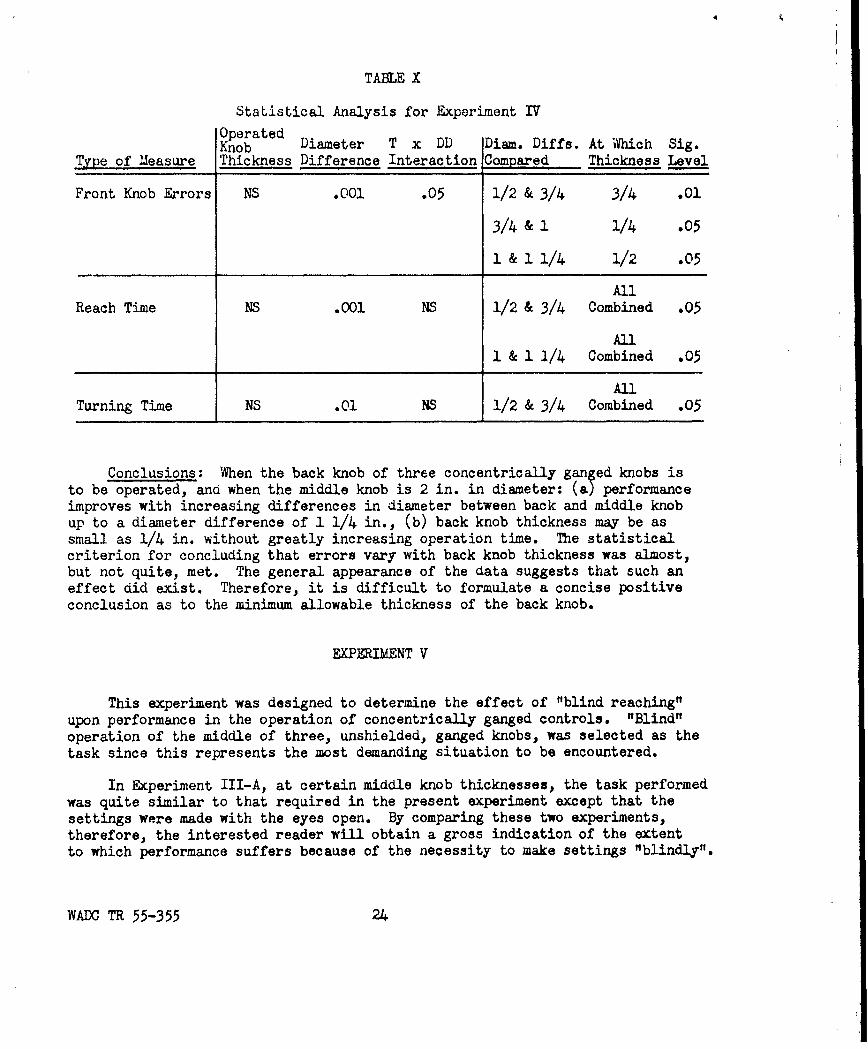
TABLE X
Statistical Analysis for Experiment IV
OperatedKnob Diameter T x DD Diam. Diffs. At Which Sig.
Type of Measure Thickness Difference Interaction Compared Thickness Level
Front Knob Errors NS .001 .05 1/2 & 3/4 3/4 .01
3/4 & 1 1/4 .05
& 1 1/4 1/2 .05
All
Reach Time NS .001 NS 1/2 & 3/4 Combined .05
All1 & 1 1/4 Combined .05
AllTurning Time NS .01 NS 1/2 & 3/4 Combined .05
Conclusions: When the back knob of three concentrically ganged knobs isto be operated, and when the middle knob is 2 in. in diameter: (a) performanceimproves with increasing differences in diameter between back and middle knobup to a diameter difference of 1 1/4 in., (b) back knob thickness may be assmall as 1/4 in. without greatly increasing operation time. The statisticalcriterion for concluding that errors vary with back knob thickness was almost,but not quite, met. The general appearance of the data suggests that such aneffect did exist. Therefore, it is difficult to formulate a concise positiveconclusion as to the minimum allowable thickness of the back knob.
EXPERIMENT V
This experiment was designed to determine the effect of "blind reaching"upon performance in the operation of concentrically ganged controls. "Blind"operation of the middle of three, unshielded, ganged knobs, was selected as thetask since this represents the most demanding situation to be encountered.
In Experiment III-A, at certain middle knob thicknesses, the task performedwas quite similar to that required in the present experiment except that thesettings were made with the eyes open. By comparing these two experiments,therefore, the interested reader will obtain a gross indication of the extentto which performance suffers because of the necessity to make settings "blindly".
WADOC TR 55-355 24
50 t00 - - M D
-MIDDLE XNOB THICK MIDDLE XN0'1/,THICK
90
40 -0
=: \ , 70o)To0 cc
at 0
X \ aw30. a: 60.
%w
~50.Nz
o1 \ ,z \ .
0 0 401N IX
"" \ \
30 \, \30.'
0 0-.
DIAMETER DIFFERENCE DIAMETER DIFFERENCE
---- 0-- MIDLE K 2/0 NICK AVOIDED
3.0. OPERATED
F2. TURNING TIME
F- L a.
"~--- " ......... -AVOIDED
REACH TIME
o. " THICKNESS OF ALLTHREE KNOBS AND
/DIAMETER DIFFERENCE0BETWEEN MIDDLE
P,' KNO AM ADJACFMDIAMETER DIFFERENCE KNOB D WME VARIED
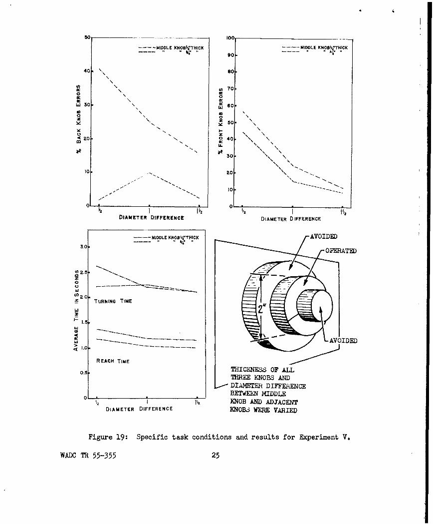
Figure 19: Specific task conditions and results for Experiment V.
WAXC T 55-355 25

TABLE XI
Statistical Analysis for Experiment V
Significance Levels from Analysis of Variance
Type of Measure Thickness Diameter Difference T x DD Interaction
Back Knob Errors .01 .01 .05
Front Knob Errors .05 .001 NS
Reach Time .01 .01 NS
Turning Time NS .05 .05
Significant (two tailed) t Tests Between Adjacent Conditions
Thicknesses At Which Sig. Diam. Diffs. At Which Sig.Type of Measure Compared Diameter Diff. Level Compared Thickness Level
Back Knob Errors 1/2 & 3/4 1/2" .01 1/2 & 1 1/2" .05
S/2 & 3/4 1" .05AUl
Front Knob Errors 1/2 & 3/4 All Combined .05 1/2 & 1 Combined .001
All1 & i 1/2 Combined .01
AllReach Time 1/2 & 3/4 All Combined .01 1/2 & 1 Combined .01
Turning Time Not Tested 1/2 & 1 1/2" .01
Conclusions: When the (2 in. diameter) middle of three, unshielded, con-centrically ganged knobs is to be operated "blindly": (a) errors can be markedlyreduced by using a middle knob thickness of at least 3/4 in., (b) even with a3/4 in. thick middle knob, a diameter cifference at which errors would be neg-ligible would probably be prohibitively large. At "reasonable" knob dimensions(i.e. middle knob 2 in. in diameter, 3/4 in. thick, diameter difference 1 1/4in.) the number of trials resulting in an error, though appreciable, is fairlylow, probably being somewhere around 10 percent.
WADC TR 55-355 26

SUMARY OF RESULTS
Of the four measures of performance taken, back knob errors appeared tobe sensitive primarily to operated knob thickness. Front knob errors respondedmost dramatically to diameter differences. Reach time was sensitive to allreal effects, although not always so sensitive to diameter differences as werefront knob errors. Turning time was virtually insensitive to knob thicknessand was generally somewhat inferior to reach time in reflecting changes in thesecond manipalated variable. Reach time, in a sense, was the best measure oferror hazard. The nonoccurrence of an error can in no way reflect the diffi-culty with which its occurrence was prevented by the operator. A time score,however, can reflect the cost of accurate performance and can do so on everytrial. Reach time was particularly well suited to be such an index of error-conduciveness, including as it did, the time necessary to assume a manual,grasping posture which would permit taking hold of the proper knob withouttouching the adjacent knobs.
A number of logical criteria can be used to arrive at "Minimum allowabledimensions". All, however, involve some arbitrary decision as to what degreeof performance decrement is intolerable. The authors used a statistical cri-terion. The largest dimension at which performance was significantly superiorto that at the next smaller one was regarded as the minimum dimension allowable.Here, of course, the size of the sample, the level of probability chosen for11significance", and the "distance" between adjacent dimensions teste all implyarbitrary decisions of the type just mentioned. Those who prefer to defineminimum dimensions as those resulting in a specified percentage of errors willfind Table XIII useful.
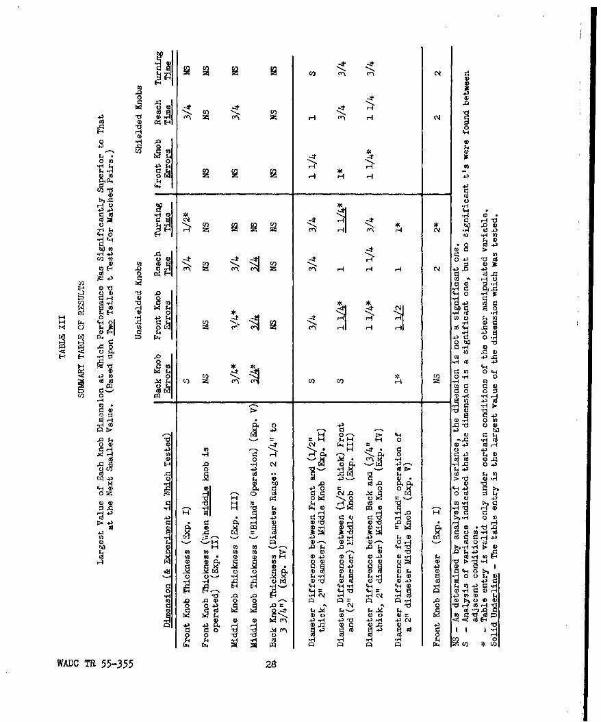
Table XII presents minimum dimensions as defined by the statistical cri-terion. The reader is strongly urged to give due weight to the following con-siderations in interpreting this summary table of results: (1) Only statis-tically significant differences between adjacent experimental values of adimension are reported. Therefore some larger nonadjacent value may be signi-ficantly superior to the value entered in the table. (2) Probably because ofthe small N used, the largest value of a cimension which is significantlysuperior to the next smaller value is frequently itself appreciably smallerthan the value at which the "curve" for the dimension levels off. (3) Thevalue entered in the table is sometimes the largest value tested in the experi-ment. This is particularly true of the "blind operation" experiment. In suchcases, much larger values might have qualified for entry into the table hadonly they been tested. (4) Statistical significance is based upon the .05level of significance for a two tailed t-test for matched pairs. This is byfar the safest procedure when the possibility of a nonnormal distribution exists.
Referring now to the summary table of results, the thickness data arefairly clear cut. Whether shielded or not, the front and second ganged knobs(of a series of either two or three ganged knobs) should be 3/4 in. thick forgood performance. The third knob may be as thin as 1/4 in. if it is the lastknob and if its diameter is in the neighborhood of 3 in. Under certain condi-tions the space between a knob and the knob behind it may have the same effectas knob thickness.
WADC Th 55-355 27
4)
00
0 -0
ho . 1 -)
4- 00 0) -4 M
42)>
0 4 aCS4*U) 4 (DN 44
0 ) 0 J3 NH0 --
W~~ * H 4b j.H4 0 H H3 HU
H2 -i -) t.
"$l (40 00 C*r4 0.(
HI co -CU4) *40 )
cdO0 -, A4 N) U) :14 W ca
0 -H H 4
o U0 4)0 H43 0 -
4-) 401-4 0'- 43 F4
(D 0 d 4 .0~~~l 40(4t:.)4
0d Ct) * 54 m.4ci ci3 V! H 3> D
0~~0 OCI04 4
0~~~~) 00)0N.0 - o(1) 0 V__ _ _ _ _ 43f
43 -f-4 -00 0-(1CI r-4. 0D0 ) 01 )
14H 0
00) U0 4) C4 or, a4)~V 0)- N) H 4 0 o .a.0 1~. 4
0 4) '0'-)~~4)4 0 0)rq OfO 4) >'d 0' 44 ) 4 0 4 t 0).rH
Oi ~ - 0 10 4, :)40- -4 ~ .00H- ;: .4 0- -4 . C)3 ( 4) o000) H0 A£0C4 al al 1: - . 0 t.0C3. H 'aI 04 £100 - rd r_ c -4 H0r. H" 14)
~ 0 4) 0.4 0 $4'
0N) 0) () 0)
0 0)0
r=44 P CI co14 :
0)D TR 55-35 0 2- 0

Since the evidence so clearly indicates that a 3/4 in. thick middle knobshould be used only the data on diameter difference for a middle knob 3/4 in.thick or more or data for all middle knob thicknesses combined, when there isno significant diameter difference by thickness interaction) will be discussed.Diameter difference data, then, inaicate that for good performance the aiameterdifference between a 2 in. diameter, 3/4 in. thick iiudlt knob &nd the frontknob should be at least 1 in. The diameter differunce between the same middleknob and the back knob shoulQ be at least 1 1/4 in. (and probably should not begreater than 1 1/2 in. - See variation of front knob errors with increasingoperated knob aiumeter in the Pilot Study.). At smaller diameter differencesthan these, performance will suffer whether shielded or unshielded knobs areused.
Data on knob diameter suggest that the optimum knob Qiameter is somewherein the neighborhood of 2 or 3 inches, that both speed and accuracy suffer at adiameter of 4 in. and that speed is reduced at a 1 in. diameter. A front knobdiameter as small as 1 in., then, can be used without increase in errors butat an additional cost in operation time.
In general, the minimum allowable dimensions for shielaed knobs have beenno smaller than those for unshielded knobs, It would appear, therefore, thatwhile shielding is of definite advantage in eliminating back knob errors and inproviuing a stationary surface upon which to print graduation marks, numbers andlabels, it contributes very little, if at all, to the saving of panel space whenthe statistical criterion for minimum allowable dimension is used.
THICKNESS CAN BE AS DISTANCE BETWEEN KNOB94ALL AS 1/4 IF FACES SHOULD BE NO
DIAMETR IS ABOUT 3 LXSS THAN 3/41AND 17 THIS IS THE
BACKHT KNOB
SHOULD BE NO LESSTHAN 1/26
SHOULD BE NO LZSSTHAN 5/8's
Figure 20: Minimum allowable dimensions for either shielded or unshieldedknobs when (a) knobs can be operated by application of moderate torque,(b) frequent inadvertent operation of adjacent controls cannot be toler-ated, (c) diameter of the middle knob is between 1 1/2 and 2 1/2 inches.
WADOC T 55-355 29

TABLE XIII
Frequency of Inadvertent Touching of Adjacent Knobs When the Front, Middle orBack Knob of Three Concentrically Mounted Knobs is Operated
Number of Times in 100 Knob Operations that an AdjacentKnob Could Have Been Thrown Off Its Proper Setting (i.e.Sum of Percentages for Back and Front Knob Errors)
Diameter Difference Unshielded Knobs Shielded KnobsBetween Operated
Operated Knob and Knob Operated Knob Thickness Operated Knob ThicknessKnob In Front of It 1/4 1/2 3/4 1 !/4 1/2 1
Front -- 4.1 .9 (.9) 0 - (-)* _ -
1/2 78.3 40.0 26.7 30.0 31.7 18.3
3/4 35.8 8.3* 8.3 15.0 11.7* 10.0Middle
1 17.5 5.8 5.8 3.3 .1 8.3
1 1/4 10.8 4.2 (o) (2.5) 0 1.7
1/2 33.3 20.8 25.0 33.3 20.8 25.0
3/4 32.5 20.8 10.0* 32.5 20.8 10.0*
1 17.5 15.8 9.2 17.5 15.8 9.2Back
3 1/4 10.8 2.5 5.0 10.8 2.5 5.0
1 1/2 3. 5.8 (.8) 3.3 5.8 (.8)
1 3/4 9.2 5.8 2.5 9.2 5.8 2.5
Minimum Allowable Dimensions CorrespondCriterion for Minimum Allowable Dimension To Table Entries Which Are:
Statistical Underlined
An adjacent knob inadvertently touched about once in100 operations. Bracketed(Three knobs operated with equal frequencies)
An adjacent knob inadvertently touched less than 10times in 100 knob operations. Starred(Three knobs operated with equal frequencies)
The 1/4 in. thickness is not recommended for the front knob since operation time was much longer at 1/4in. than at the 1/2 in. thickness.
WADC TR 55-355 30

GENERAL DISCUSSION
The large diameter differences which are necessary to prevent front knoberrors strongly suggest that (when the avoidance of inadvertent operation ofadjacent, nondatent, concentrically mounted controls is a critical consideration),panel space will seldom be saved by mounting knobs on concentric shafts. TableXIV permits a comparison of the amorunt of panel area consumed by concentricallyganged knobs versus that consumed by the same number of nonganged knobs. Itwill be seen that if a 1 in. diameter difference be used (the smallest diameterdifference that would be used if errors were an important consideration) con-centrically ganged controls, with one trivial exception, actually require morepanel space than the same number of 1/2 in. diameter isolated knobs.
TABLE XIV
Panel Area (Times 64/7r) Required for a Given Number of Knobs WhenThey Are Concentrically Ganged Versus That Required When They are Completely
Isolated from Each Other (Diameter of Front Ganged Knob: 1/2 Inch)
"Clear Space"Margin To BeLeft Around
No. of Knobs for Diameter Difference Between Diameter ofKnobs Finger Clearance Ganged Knobs Isolated Knobs
_____ ______A_ I/ I./ iza I/ i
2 None 16 25 36 49 8 18 32
2 1/2" 64 81 100 121 72 98 128
2 3/4" 100 121 144 169 128 162 200
2 lIt 14 169 196 225 200 242 288
3 None 36 64 100 14 12 27 48
3 1/2" 100 14 196 256 108 147 192
3 3/4" 14 196 256 324 192 243 300
3 1" 196 256 324 400 300 363 432
The comparison becomes more unfavorable to the concentrically ganged knobswith greater front knob diameter, greater diameter difference, and with largernumbers of knobs to be ganged. Even with large margins for finger clearance(around the backmost ganged knob and around all of the isolated knobs with which
WADC TR 55-355 31
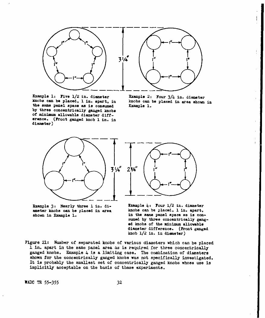
Example 1: Five 1/2 in. diameter Example 2: Four 3/4 in. diameterknobs can be placed, 1 in. apart, in knobs can be placed in area shown inthe same panel space an is consumed Example 1.by three concentrically ganged knobsof minimum allowable diameter diff-erence. (Front ganged knob 1 in. indiameter)
Example 3: Nearly three 1 in. di- Example 4t Four 1/2 in. diameterameter knobs can be placed in area knobs can be placed, 1 in. apart.shown in Example 1. in the same panel space as is con-
sumed by three concentrically gang-ed knobs of the miniwmu allowablediameter difference. (Front gangedknob 1/2 in. in diameter)
Figure 21: Number of separated knobs of various diameters which can be placed1 in. apart in the same panel area as is required for three concentricallyganged knobs. Example 4 is a limiting case. The combination of diametersshown for the concentrically ganged knobs was not specifically investigated.It is probably the smallest set of concentrically ganged knobs whose use isimplicitly acceptable on the basis of these experiments.
WADC TR 55-355 32

the comparison is made) no appreciable amount of panel space is saved by concen-trically ganging two knobs unless the isolated knobs with which the comparisonis made are of large diameter. The table used completely isolated knobs as thecomparison. If the nonconcentrically ganged knobs, however, are arranged in amatrix so that the same "margin" can serve for adjacent knobs, the comparisonbecomes still more unfavorable to the concentrically ganged knobs. (Fig. 21)The allowable spacing of separated knobs arranged in matrices has been investi-gated under very nearly the same task conditions, measurements, etc., as in thepresent series of experiments (2). The results of this research indicate that,generally speaking, three small diameter knobs arranged in a matrix result inconsiderably fewer errors than do three concentrically ganged knobs consumingthe same amount of panel space. The data comparisons leading to this conclusionare extensive and complicated and do not lend themselves to concise presentation.The interested reader, therefore, is invited to consult the original dataincluded in both this report and that concerning knob crowding for substantia-tion of the contention that "crowding" small diameter knobs is a more efficientmeans of economizing on panel space than is mounting a series of knobs on con-centric shafts.
It should be emphasized that the foregoing reasoning is specific to thefollowing conditions: (a) the knobs in question are continuous rotation (i.e.low friction) knobs, (b) frequent inadvertent operation of adjacent coaxialknobs cannot be tolerated, (c) the primary purpose of mounting the knobs onconcentric shafts is to save panel space. Where these conditions obtain, itwould usually be undesirable concentrically to gang more than two knobs andwould frequently be undesirable even for two.
Concentrically ganged controls may still be desirable, however, under thefollowing conditions: (a) when the knob operations involved are sequentiallyor functionally related, particularly when it is necessary or desirable to pro-ceed from one knob to another without visual reference, (b) when neither inad-vertent operation of adjacent knobs nor small delays are critical (e.g. If oneknob of a television set controls "focus", the other "volume", the operator willreceive immediate visual or auditory feedback of inadvertent operation of anadjacent control which he can then correct with negligible delay.) Here smalldifferences in diameter can be used, and panel space can therefore be saved.(c) when large diameter knobs must be used whether the knobs are ganged orisolated, (d) when it is necessary to save space behind the panel, (e) whendetent knobs are to be used, or when certain combinations of detent and con-tinuous rotation knobs are to be used. Detent knobs necessarily consume con-siderable panel area since a large lever arm is necessary to exert the requiredtorque. A very slightly larger continuous-rotation knob could be placed behindthe detent knob at a very small additional cost of panel space. "Front knoberrors", when the continuous rotation knob is operated, would be irrelevantsince a detent knob cannot be thrown off its setting by a mere touch. Backknob errors, when the detent is operated, could be eliminated by shielding, orcould be reduced by increasing the thickness of the detent or by spacing itfarther in front of the continuous rotation knob. Panel space would have beensaved. Finally, subjects in these experiments were instructed to work forboth speed and accuracy. Where speed is not a consideration, accuracy mayincrease accordingly and smaller diameter differences may be tolerable, at theexpense, however, of additional "strain" upon the conscientious operator inmaking an accurate setting.
WADC TR 55-355 33
BIBLIOGRAPHY
1. Bradley, J. V. Control-ciisplay association preferences for ganged controls.WADC Technical Report 54-379, August 1954.
2. Bradley, J. V. & Stump, N. E. Minimum allowable knob crowaing. WADC Tech-nical Report 55-455, December 1955.
3. Lindquist, E. F. Design and Analysis of Experiments in Psychology andEducation. New York: Houghton Mifflin Co., 1953, 237-238 and 301.
4. Wilcoxon, F. Some Rapid Approximate Statistical Procedures. AmericanCyanamid Co., 1949, 5-6 and 13.
WADOC TR 55-355 34

APPENDIX
NUMBER AND PERCENT OF ERRORS AND AVERAGED REACH ANDTURNING TIME SCORES FOR EACH OF THE SEPARATE EXPERIMENTS
wADC TR 55-355 35

'j r--4t~ r'- o t-
Q'4 0 tC-H( ('q.O fl, 0-1
-4H( OVH
0), 0 4-\ 0 *l C) 4(1 0 (D C.
(n 0'4 (N o, f,2 (, E,' toJ c- H- Lrf0 n~~' C(r-c
C-A 0\V r-AVV ~ " ' (N(H0* H T-4 .LIC~
tCl\ r'' C~tO-z ~ C-4 (1 (, co HHCH
Qv Hl (n 0- 0 0o 4- '0 DC' - -Vl- a,0 D .*0)- c",c CV He(N H*H - H
Ho (' -4 -4'ON-4 -4 H(O Ot u~CN -t
(2' UN~H HH- (N * (-% HH'
rHuC~' H &0-4 H
N (Ni 0'00 -4.0~- 0~~' *r r- () 0- n H
E-' 0) H C -0 0 o I t'\ OH- H 't ~ . .' H .
H ( -4 O c' \ 1-4 r-. -4 r-I- C' O -q
(N n 044N~ 0O V m* IN rIY)L\'
t0 C- 0 l% )C
0) *A *) mNH O C - -t\ ' (O *tm0
0 t-' OCV0C El-zC"( *o *I *r (NHto Ct'
C;~ Z *; U'00\~ 'or- 0i o o4m
0) C S.. M 00 ' -q-4W 'c\ wo r-It0(v- -O0 C'00'O CYN m C, C, -ri m V-t
'(t 0\i( OH vJ H *.. 0 ' ,-C- ..
r-4 0- 00l mo CI 00 0'.X"' (Do- " a, -,out
C, C't~ HYI 02NH- H . . NHHHqc
H 0 ( ll V "~~~CV~~~G 0'0' 0\OC' * 00 N (N ml
$4 V0OH C! C- ;A' -* m (NHH(N\ o10
olC%10,( 0 NAol0H - Nc~' NVf -A oOc",00.0 ~~ C')-'C VV1~0 *
c0 H H *R *Y ' y -Ct H EHH11
rx I 0'Y - 01) 0)
A- . C; C;-4. 4-V r-4 l 0- S.. U- r " -
0 M~D UA'\ mo0 El- ~ 0 S40NO00. s.0 t- 00- LA0o- N) El .d.lN r -
cu' (NrI- - A C,8 c -An, L\r c 7
4AD Th 5535 36- o- j\ I -0 l

TA1L, I IT
','';, -,?T PrI TV: AND AV''AG"fD TTI. CoR FOR E7TZPRI.'NTS I-A and I-B
EYJ 'RIIENT I-A EXPEtIhENT I-B
Front Front Knob Thickness Front Knob ThicknessKnob
Measure Diameter 1/4 1/2 3/4 1 All 1/4 1/2 3/4 1 All
1 3 0 1 0 4
Total 2 2 2 0 0 4Number Iof 3 2 1 1 0 4 No Data Taken
Errors4 6 0 1 0 7
All 13 3 3 0 19
1 3.75 0 1.25 0 1.25
2 2.50 2.50 0 0 1.25Percen
3 2.50 1.25 1.25 0 1.25 No Data TakenErrors
4 7.50 0 1.25 0 2.19
All 4.06 .94 .94 0 1.49
1 .8531 .6605 .6153 .5459 .6687 .5556 .5470 .4943 .4820 .5197
2 .8055 .6224 .5426 .5289 .6249 .4888 .5100 .4389 .4564 .4735AveragvReach 3 .7731 .6170 .5228 .5096 .6056 .4736 .4901 .4670 .4205 .4628Time
4 .7608 .6155 .5510 .5276 ,6137 .4534 .4989 .4268 .4384 .4544
All .7981 .6289 .5579 .5280 .6282 .4929 .5115 .4568 .4493 .4776
1 1.845 1.387 1.337 1.366 1.484 1.494 1.460 1.510 1.418 1.470
2 1.346 1.279 1.212 1.186 1.256 1.291 1.148 1.278 1.208 1.231Averagerning 3 1.392 1.191 1.190 1.083 1.214 1.199 1.298 1.156 1.050 1.176
Time 4 1.433 1.327 1.297 1.179 1.309 1.338 1.363 1.320 1.266 1.322
All 1.504 1.296 1.259 1.204 1.316 1.330 1.717 1.316 1.236 1.300
WAMC TR 55-35r 37
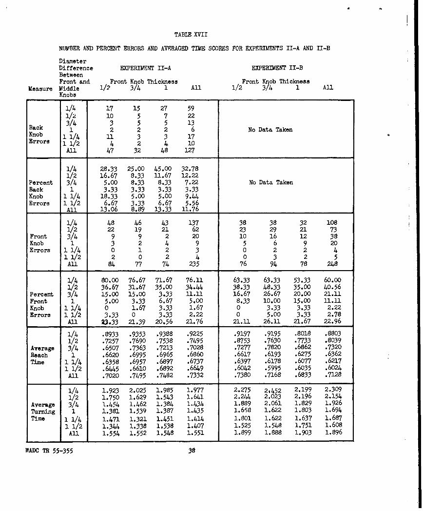
TABLE XVII
NUMBER AND PERCENT ERRORS AND AVERAGED TIME SCORES FOR EXPERIMENTS II-A AND II-B
DiameterDifference EXPERIMENT II-A EXPERIMENT II-BBetweenFront and Front K ob Thickness Front Knob Thickness
Measure Middle 1/2 3/24 1 All 1/2 3/4 1 AllKnobs
1/4 17 15 27 591/2 10 5 7 223/4 3 5 5 13
Back 1 2 2 2 6 No Data TakenKnob 11/4 11 3 3 17Errors 1 1/2 4 2 4 10
All 47 32 48 127
1/4 28.33 25.00 45.00 32.781/2 16.67 8.33 11.67 12.22
Percent 3/4 5.00 8.33 8.33 7.22 No Data TakenBack 1 3.33 3.33 3.33 3.33Knob 1 1/4 18.33 5.00 5.00 9.44Errors 1 1/2 6.67 3.33 6.67 5.56
All 13.06 8.89 13.33 11.76
1/4 48 46 43 137 38 38 32 1081/2 22 19 21 62 23 29 21 73
Front 3/4 9 9 2 20 10 16 12 38Knob 1 3 2 4 9 5 6 9 20Errors 1 1/4 0 1 2 3 0 2 2 4
1 1/2 2 0 2 4 0 3 2 5All 84 77 74 235 76 94 78 248
1/4 80.00 76.67 71.67 76.11 63.33 63.33 53.33 60.001/2 36.67 31.67 35.00 34.44 38.33 48.33 35.00 40.56
Percent 3/4 15.00 15.00 3.33 11.1 16.67 26.67 20.00 21.11Front 1 5.00 3.33 6.67 5.00 8.33 10.00 15.00 11.llKnob 1 14 0 1.67 3.33 1.67 0 3.33 3.33 2.22Errors 1 1/2 3.33 0 3.33 2.22 0 5.00 3.33 2.78
All 23.33 21.39 20.56 21.76 21.11 26.11 21.67 22.96
1/4 .8933 .9353 .9388 .9225 .9197 .9195 .8018 .88031/2 .7257 .7690 .7538 .7495 .8753 .7630 .7733 .8039
Average 3/4 .6507 .7363 .7213 .7028 .7277 .7820 .6862 .7320Reach 1 .6620 .6995 .6965 .6860 .6617 .6193 .6275 .6362Time 1 1/4 .6358 .6957 .6897 .6737 .6397 .6178 .6077 .6217
1 1/2 .6445 .6610 .6892 .6649 .6042 .5995 .6035 .6024All .7020 .7495 .7482 .7332 .7380 .7168 .6833 .7128
1/4 1.923 2.025 1.985 1.977 2.275 2t452 2.199 2.3091/2 1.750 1.629 1.543 1.641 2.244 2.023 2.196 2.154
Average 3/4 1.454 1.462 1.384 1.434 1.889 2.061 1.829 1.926Turning 1 1.381 1.539 1.387 1.435 1.658 1.622 1.803 1.694
Time 1 1/4 1.471 1.321 1.451 1.414 1.801 1.622 1.637 1.6871 1/2 1.344 1.338 1.538 1.407 1.525 1.548 1.751 1.608
All 1.554 1.552 1.548 1.551 1.899 1.888 1.903 1.896
WADC TR 55-355 38

TABLE XVIII
NUMBER AND PERCENT ERRORS AND AVERAGED TIME SCORES FOR EXPERIMENTS III-A AND III-B
Diameter EXPERIMENT III-A EXPERIMENT III-BDifferenceBetween Middle Knob Thickness Middle Knob ThicknessFront and
Measure Middle Knobs. 1/2 3/4 1 1/2 with All 1/2 3/4 1 1/2 with Alli/"1 gap 1/2" gap
1/2 30 9 6 2 473/4 15 4 0 3 22
Back 1 10 3 2 2 17
Knob 1 1/4 13 3 0 0 16 No Data TakenErrors All 68 19 8 7 102
1/2 25.00 7.50 5.00 1.67 9.793/4 12.50 3.33 0 2.50 4.58
Percent 1 8.33 2.50 1.67 1.67 3.54Back 1 1/4 10.83 2.50 0 0 3.33 No Data TakenKnobErrors All 14.17 3.96 1.67 1.46 5.31
1/2 64 39 26 22 151 36 38 22 29 125
Front 3/4 28 6 10 17 61 18 14 12 8 52
Knob 1 11 4 5 8 28 4 4 10 3 21
Errors 1 1/4 0 2 0 0 2 3 0 2 1 6
An 103 51 41 47 242 61 56 46 41 204
Percent 1/2 53.33 32.50 21.67 18.33 31.46 30.00 31.67 18.33 24.17 26.04
Front 3/4 23.33 5.00 8.33 14.17 12.71 15.00 11.67 10.OO 6.67 10.83
Knob 1 9.17 3.33 4.17 6.67 5.83 3.33 3.33 8.33 2.50 4.37
Errors 1 1/4 0 1.67 0 0 .42 2.50 0 1.67 .83 1.25
All 21.46 10.62 8.54 9.79 12.60 12.71 11.67 9.58 8.54 10.62
1/2 .7342 .6712 .6239 .6388 .6670 .7558 .6706 .6582 .6618 .68663/4 .7039 .6222 .5737 .5800 .6200 .6860 .6243 .6148 .5938 .6297
Average 1 .6476 .5858 .5501 .5511 .5836 .6632 .6336 .5882 .5980 .6208Reach 1/14 .6398 .5740 .5550 .5504 .5798 .6757 .6140 .5915 .5889 .6175Time
All .6814 .6133 .5757 .5801 .6126 .6952 .6356 .6132 .6106 .6386
1/2 1.498 1.445 1.352 1.296 1.398 1.693 1.465 1.472 1.424 1.5143/4 1.443 1.206 1.198 1.287 1.283 1.417 1.403 1.388 1.300 1.377
Average 1 1.363 1.147 1.230 1.258 1.249 1.346 1.372 1.371 1.327 1.354TurninE 1 1/4 1.242 1.221 1.199 1.208 1.218 1.328 1.382 1.398 1.281 1.347Time
All 1.387 1.255 1.245 1.262 1.287 1.446 1.405 1.407 1.333 1.398
WADC TR 55-355 39

TABLE XIX
NUMBER AND PERCENT ERRORS AND AVERAGED TIME SCORES FOR EXPERIMENT IV
Diameter Difference Back Knob Thickness
Between
Measure Back and Middle Knobs 1/4 1/2 3/4 All
1/2 40 25 30 953/4 39 25 12 761 21 19 11 51
Errors 1 1/4 13 3 6 2211/2 4 7 1 12
1 3/4 11 7 3 21
All 128 86 63 277
1/2 33.33 20.83 25.00 26.393/4 32.50 20.83 10.00 21.111 17.50 15.83 9.17 14.17
Percent 1 1/4 10.83 2.50 5.00 6.11Errors 1 1/2 3.33 5.83 .83 3.33
1 3/4 9.17 5.83 2.50 5.83
All 17.78 11.94 8.75 12.82
1/2 .7524 .6933 .7230 .7229
3/4 .6776 .6669 .6581 .6675Average 1 .6667 .6494 .6326 .6496
Reach 1 1/4 .6400 .6289 .6108 .6266
Time 1 1/2 .6339 .6014 .6335 .6229
1 3/4 .6230 .6442 .5981 .6218
All .6656 .6474 .6427 .6519
1/2 1.560 1.417 1.575 1.5173/4 1.435 1.322 1.355 1.371
Average 1 1.325 1.378 1.320 1.341Turning 1 1/4 1.298 1.352 1.272 1.307Time 1 1/2 1.326 1.272 1.329 1.309
1 3/4 1.259 1.349 1.268 1.292
All 1.367 1.348 1.353 1.356
WADC TR 55-355 40

TABLE XX
NMVBER AND PERCENT ERRORS AND AVERAGED TIE SCORES FOR EXPERIMENT V
Diameter Difference Thickness of All Three KnobsBetween Viddle and
Measure Front and Back Knobs 1/2 3/4 All
/2 49 2 51
1 30 12 42BackKnob 1 1/2 19 3 22Errors
All 98 17 115
1/2 40.83 1.67 21.25
Percent 1 25.00 10.00 17.50BackKnob 1 1/2 15.83 2.50 9.17Errors
All 27.22 4.72 15.97
1/2 68 53 121
Front 1 30 19 49KnobErrors 1 1/2 14 10 2h
All 112 82 194
1/2 56.67 44.17 50.42
Percent 1 25.00 15.83 20.42FrontKnob 1 1/2 11.67 8.33 10.00Errors
All 31.11 22.78 26.95
1/2 1.365 1.165 1.265
Average 1 1.199 1.045 1.122ReachTime 1 1/2 1.160 1.000 1.080
All 1.241 1.070 1.156
1/2 2.601 2.221 2.411
Average 1 2.196 2.256 2.226
TurningTime 1 1/2 2.121 2.108 2.114
All 2.306 2.195 2.251
WADOC TR 55-355 41

UNCLASSFIE
tot
rme derviceJ c Infl 1'Reproduced by
DOCUMENT SERVICE CENTERKNOTT BUILDING, DAYTON, 2, OHIO
This document is the property of the United States Government. It is furnished for the du-ration of the contract and shall be returned when no longer required, or upon recall by ASTIAto the following address: Armed Services Technical Information Agency,Document Service Center, Knott Building, Dayton 2, Ohio.
NOTICE: WHEN GOVERNMENT OR OTHER DRAWINGS, SPECIFICATIONS OR OTHER DATAAREUSD FOR ANY PURPOSE OTHER THAN IN CONNECTION WITH A DEFINITELY RELATEDGOVERNMENT PROCUREMENT OPERATION, THE U. S. GOVERNMENT THEREBY INCURSNO RESPONSIBILITY, NOR ANY OBLIGATION WHATSOEVER; AND THE FACT THAT THEGOVERNMENT MAY HAVE FORMULATED, FURNISHED, OR IN ANY WAY SUPPLIED THESAID DRAWINGS, SPECIFICATIONS, OR OTHER DATA IS NOT TO BE REGARDED BYIMPLICATION OR OTHERWISE AS IN ANY MANNER LICENSING THE HOLDER OR ANY OTHERPERSON OR CORPORATION, OR CONVEYING ANY RIGHTS OR PERMISSION TO MANUFACTURE,USE OR SELL ANY PATENTED INVENTION THAT MAY IN ANY WAY BE RELATED THERETO.
UNCLASSIFIEDi