to - defense technical information center · -p organization da-44-188-ard-2 i 9- performing...
TRANSCRIPT

UNCLASSIFIED
AD NUMBER
ADB951717
NEW LIMITATION CHANGE
TOApproved for public release, distributionunlimited
FROMDistribution authorized to U.S. Gov't.agencies and their contractors;Administrative/Operational Use; DEC 1968.Other requests shall be referred toDepartment of the Army, Attn: PublicAffairs Office, Washington, DC 20310.
AUTHORITY
HUMRRO D/A ltr 8 Jul 1980
THIS PAGE IS UNCLASSIFIED

THIS REPORT HAS BEEN DELIMITED
AND CLEARED FOR PUBLIC RELEASE
UNDER DOD DIRECTIVE 5200,20 AND
NO RE RICTIONS ARE IMPOSED UPON
ITS USE AND DI8CLOSUREo
Di STRiBUTION STATEMENT A
APPROVED FOR PUBLIC RELIA$EJ
DISTRIBUTION UNLIMITED$
* UNANNOUNCED "--75
! HumnlifO
T DTIC7 ft ELECTE
-_, JUN 4 1980
B
I~ ~&- The George Washington UniversityHUMAN RESOURCES RESEARCH OFFICE
operating iuder contract withTHlE DEPARTMENT OF THlE ARMY
80 5 "23 014Approved for public release;
distribution unlimited
"lip*
This material has been prepared for review by appropriateresearch or military agencies, or to record research informationon an interim basis. J
The contents do not necessarily reflect the official opinionor policy of either the luman Resources Research Office or theDepartment of the Army. IML
]3
; Ii
It
The Human Resources Research Office is a nongovernmentalagency of The George Washington University, operating under -
contract with the Department of the Army. flumRRO's missionndis to conduct research in the fields of training, motivation,
and leadership.
__j
.1'

03 3 '3 " ,
UNCLASSIFIEDSECURITY CLASSIFICATION OF THIS PAGE (When Date Entered)
REPORT DOCUAEATI0N PAGE READ rNSTRUCNM'1____________________ , P EEFORE COMPLETING FORM
1. REPORT NUMBER 12. GOVT ACCESSION NO. 3. RECIPIENTVS CATALOG NUMBER
4. TITLE (and Subtitle) S. TYPE OF REPORT & PERIOD COVERED
,EVALUATION OF THEaURATION OFLY THROUGH Staff PaperMTAINED ENTRAC NG WITH THE SPEED RING SIGHT G. PERFORMING ORG. REPORT NUMBERON THE -5 W ON .5 1-- 1
L -AU-THOR(° )...-- - 0. CONTRACT OR GRANT NUMBER(s)' Albert L T.Kubai Harold E. Chtistensen .
- P ORGANIZATION DA-44-188-ARd-2 I
9- PERFORMING ORGANIZATION NAME AND ADDRESS .O. PROGRAMTE1AR T, 17GfEW
Human Resources Research Organization (HumRRO) AREA & WORK UNIT NUMBERS
300 N. Washington StreetAlexandria, VA 22314
11. CONTROLLING OFFICE NAME AND ADDRESS -- . REPORT DATF
Department of the Army / e&O 6 &-
1714. MONITORING AGENCY NAME & ADDRESS(If dlfferent from Controlling Office) IS. sf.CURITY CLASS. (of this report)
Unclassified/)t5a ISA. DECLASSIFICATIOIi/DOWNGRADINGSCHEDULE
Z :16. DISTRIBUTION STATEMENT (of thie Report)
Approved for public release; distribution unlimited.
17. DISTRIBUTION STATEMENT (of the abstract entered In Block 20, If different from Report)-
I8. SUPPLEMENTARY NOTES
Research performed under HumRRO Project SKYFIRE.
C,-
13. KEY WORDS (Coninue on reverse aide If necessary and Identify by block lumbor)
firing techniqueslead firing techniqueantiaircraft weaponsgun sightstracking
20. ABSTRACT (Continue on reverse idae if necoseary end Identitfy by block number)In studying the various firing techniques or strategies that might be used iroperating conventional antiaircraft weapons, several strategies might be en-umerated. One of the more commonly used is the constant lead firing tech--nique. This report presents an evaluation of the effectiveness of the con-stant lead technique on the basis of the weapon speed ring characteristicsof the M-18 Reflex sight mounted on the quad .50 caliber M-55 weapon, assuming optimum tracking performance.
DD I jJN73 1473 EoiTION OF I NOV 65 IS OBSOLETE
SECURITY CLASSIFICAYION OF TillS PAGE (RThen Date Entered)
. ...... _ _._i... .. .. .. 4 2)...;3 - .
~i
~I
.Staff Paper
I EVALUATION OF THE DURATION OF FLY THROUGH
OBTAINED WHEN TRACKING WITH THE SPEED RING SIGHT
ION THE M-55 WEAPON
by.. Albert L. Kubala
-" and
Harold E. Christensen
This Staff Paper has been prepared for disseminationwithin HumRRO for purposes of information or coordinationinternal to the organization. It does not necessarilyrepresent official opinion or policy of either the Human
low Resources Research Office or the Department of the Army.
:'' - , December 1968 D|
SHumRRO Division No. 5 (Air Defense) ELECTEF The George Washington University JUN 4 1980D
HUMAN IESOURCES RESEARCH OFFICEoperating under contract with
THE DEPARWNT OF TIE ARMY B
Approved for public release;distribution unlimited

IPREFACE
The data presented in the paper were collected in connectionSwith research being conducted under HumRRO Work Unit SKYFIRE.
In studying the various firing techniques or strategies whichi 'might be employed in the operation of conventional anti-aircraft
weapons, several strategies might be enumerated. One of the morecommonly used is the constant lead firing technique. This report
U presents an evaluation of the effectiveness of the constant leadI technique on the basis of the weapon speed ring characteristics
of the M-18 Reflex sight mounted on the quad .50 caliber M-55weapon, assuming optimum tracking performance.
I
I
ACCESSION for
o[NTIS White Section r0
DDC Buff Section [
-'V UNA NNOUCED
Dist. AVAIL and/or S EIi
iiie
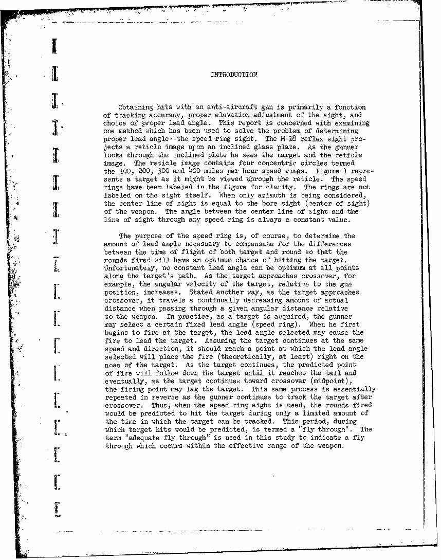
V -1. IN~TRODUCTION
Obtaining hits with an anti-aircraft gun is primarily a functionof tracking accuracy., proper elevation adjustment of the sight, and
Q choice of proper lead angle. This report is concerned with examiningone method which has been used to solve the problem of determiningproper lead angle--the speed ring sight. The M-18 reflex sight pro-jects a reticle image uron an inclined glass plate. As the gunner
i looks through the inclined plate he sees the target and the reticleimage. The reticle image contains four concentric circles termedthe 100, 200, 300 and 400 miles per hour speed rings. Figure I repre-
ii sents a target as it might be viewed through the reticle. The speed...." rings have been labeled in the f;gure for clarity. The rings are not
labeled on the sight itself. When only azimuth is being considered,the center line of sight is equal to the bore sight (2enter of sight)of the weapon. The angle between the center line of -ighr and theline of sight through any speed ring is always a constant value.
T The purpose of the speed ring is, of course, to determine the
bL amount of lead angle necessary to compensate for the differences
between the time of flight of both target and round so that therounds fired will have an optimum chance of hitting the target.Unfortunateiy, no constant lead angle can be optimxm at all pointsalong the target's path. As the target approaches crossover, forexample, the angular velocity of the target, relative to the gunposition, increases. Stated another way. as the target approachescrossover, it travels a continually decreasing amount of actualdistance when passing through a given angular distance relative
I to the weapon. In practice, as a target is acquired. the gunnermay select a certain fixed lead angle (speed ring). When he firstbegins to fire at the target, the lead angle selected may cause thefire to lead the target. Assuming the target continues at the samespeed and direction, it should reach a point at which the lead angleselected will place the fire (theoretically, at least) right on thenose of the target. As the target continues, the predicted point
L of fire will follow down the target until it reaches the tail andeventually, as the target continueo toward crossover (midpoint),the firing point may lag the target. This same process is essentiallyrrepeated in reverse as the gunner continues to track the target aftercrossover. Thus, when the speed ring sight is used, the rounds firedwould be predicted to hit the target during only a limited amount of
r the time in which the target can be tracked. This period, duringwhich target hits would be predicted, is termed a "fly through". Theterm "adequate fly through" is used in this study to indicate a fly
through which occurs within the effective range of the weapon.

77 7" --, ' 7- -- Iz
7 -
At 100 200 300 400
Iq " Figure 1. Schematic Representation of Target as Viewed ThroughSpeed Ring Sight
[ 2
i If an inappropriate speed ring is selected, the lead angle maybe either too large or too small, so that fire will lead or lag thetarget at all times and no fly through will be obtained. Target
. -speed obviously has a very great effect on the selection of an cpti-mum speed ring. However, since range of target, as well as speed,affects the lead angle required, it cannot be categorically statedbhat an aircraft travi-uing at a given speed should always be trackedusing the same sT'-ed ring.
On +'.e M-18 sight, the miles per hour values of the speed ringsare ,ot to be interpreted directly. Firing doctrine states thattargets should be tracked with a speed ring equal to 3/4 of the targetspeed.l/ There is, however, some question as to whether an adequate
J. fly through can be obtained at all ranges following this doctrine.
-i The question as to how much latitude is allowable in the estima-tion of target speed also further complicates the firing problem.If, for example, there are some situations in which only a relatively
small error in target speed estimation would result in not obtaininga fly through, this would impose serious limitations.
To evaluate effec7tveness of a speed ring sight, it was considerednecessary to compute the location on the target path where fly through
J would occur unde' various conditions of crossover range, target speed,and choice of speed ring. Three questions were of primary concern:(1) Under what conditions will fly through be obtained? (2) What isthe duration of fly through? (3) Where along the tracking course,with respect to crossover, does the fly through occur?
Ii METHOD
, IThe kind of information needed was obtained by plotting the angular
distance at which a fly through will occur under various combinations
of target speeds, crossover ranges and speed rings.
L Conditions of fly through were predicted by the formula
R(Tan 4)Tan @) = V )
VDepatmen of the Army, Field Manual 44h-57, Service of the Piece-Multiple Caliber .50 Machine Gun, 7 September 1951, p. 100.
3I"
L
where R = Crossover :range.
4) = angle between crossover and line of sight usingthe chosen speed ring (when tracking the nose ofthe target).
9 = angle between crossover and bore sight (center ofsight).
Vt= velocity of target#
TR= time required for round fired to reach predicted
intercept.
The first half of the equation--R(Tan 4 - Tan g)--represents thev distance which the target must travel from fire to intercept asL determined by the lead angle of the speed ring sight. The second
half of the equation--V (TR)- -represents the distance which thetarget will travel based on target speed and weapon ballistic data.Using assumed values of target speed, crossover range and speedring, the value for angle 9 was obtained. The value of 9 was usedto determine the distance from crossover at which the fly through
I iwould be predicted to commence. To predict the end of the flythrough, the quantity of 16 yds. (representing the target length)was added to the product on the left side of the equation. Thevalue 16 yds. is, of course, arbitrary and is not intended to implyany actual aircraft length. It should be noted that computationswere based on tracking the nose of the target, while weapon doctrineadvocates tracking center of mass. This was done because center ofmass is not an easily measurable quantity, differing as it does from
- one aircraft type to another. Angular areas of fly through usingcenter mass tracking will differ slightly from those reported in
- this study.
T;.e angles between speed rings and the center line of sight were
determined empirically by two different observers. The speed ring1 I values used in this study were as follows:
Speed Rir:E Angle from Center Line of Sight
1 100 3.6550
200 7.5160
300 11.920'
Wo0 16.918 °
~4

Crossover ranges were selected (within the effective range ofthe weapon) and fly through paths computed for a sample of speedring-target speed combinations.
RESULTS
C Figure 2 presents an example of three tracking plots using the
300 speed ring to track targets at a crossover range of 500 meters.Assuming perfect tracking, the figure shows where rounds fired atvarious angular distances prior to crossover would be predicted to
4 Ilead, lag, or hit the target. For instance, assume a weapon is track-
ing a 404 mph target at this range with the 300 speed ring; at 250
before crossover the round would be redicted to lead the targetby approximately 9-1/2 meters, at 20 the round should just hitthe nose of the target, at crossover (00) the round should hit thetail of the target. (The target was assumed to be 16 meters longin computations.) Again, using the same speed ring to track a 624mph target flying at the same range, a round fired at 430 prior toc-rossover would be predicted to lag the nose of the target by approxi-mately 27 meters. It can be noted that if a target slower than 355mph w-2- tracked, using this speed ring, the fire would always leadthe target. If targets at speeds greater than 624 mph are tracked,the range to Lhe aircraft at the time of fly through will be beyond
L !weapon effecti. range. The three tracking plots in Figure 2 (355mph, 404 mph, and '?4 mph) illustrate respectively a minimum, optimum,and maximum target ,peed. The minimum speed for fly through was definedhere as the slowes target speed (at a given crossover range) at whichthe speed ring used will obtain a hit. Under this condition, the pro-jectiles would be predicted to just hit the nose of the target atcrossover (assuming perfect tracking). The optimum speed for flythrough was defined as that target speed which yields a complete flythrough surrounding crossover. This is the longest fly through ob-
tainable in terms of both time duration and angular distance. Themaximum speed for fly through was the maximum target speed at whicha fly through can be obtained within the weapon's effective rangewhich, for the computations performed. was assumed to be 800 meters.Figure 2 illustrates the minimum, optimum, and maximum target speedsfor obtaining fly through under only one set of range-speed ringconditions. Since variation in range of target had an effect onfly through, it was felt that fly through data should be examinedacross several target crossover ranges.
Minimum, optimum, and maximum target speeds for obtaining flythrough at several target ranges are presented in Table 1. In
Figures 3: 4, and 5, the minimum and maximum target speeds which
5

AREA OF PREDICTED FLY THROUGHI. r.L
a).4-' )U
0)Q
S. if 0J0)A4-' r- 1)
.cli >S-
C,.)
- -' e U-
0 --
APPROXIMATE LIMif OF THE EFF-ECTVERAtqGE-DFTHE WEAPON i
4C.uj. u4-) S-
I 0 0
I a:
0 0 t7
rz ! 4!
LL .
wo S.
1CL 4)LL0)
0-~
0 00> f
+ +' I
DIFFERENCE (in meters) BETWEEN THE PREDICTED POSITIONS OF ROUND AND TARGET
F 6

TABLE 1
Characteristics of Fly Throughas Determined by
Range and Aircraft Speeds
Crossing Range Minimum Optimum Maximum Target Speed Whichand Target Target Allows a Fly ThroughL Speed Ring Speed Speed Within an 800 yd Slant Ranged 4 700M - 2 209 mph 242 mpha 226 mph
3 334 mph 368 mph 371 mph4 482 mph 515 mph 551 mph
J 500M - 2 222 mph 271 mph 358 mph3 355 mph 404 mph 624 mph4 511 mph 560 mph 1041 mph
V 300M -2 235 mph 322 mph 716 mph3 376 mph 463 mph 1525 mph4 542 mph 629 mph 3537 mph
_ 200M - 2 243 mph 378 mph 1373 mph3 390 mph 541 mph 3500 +mph4 561 mph ' 697 mph 3500 +mph
100M - 2 245 mph 517 mph 3500 +mph" 3 393 mph 665 mph 3500 +mphL 4 566 mph 838 mph 3500 +mph
a/Computed optimum target speed produces a fly through which isL beyond effective range of the weapon.
7

CD000
(a
0-)
Lii 0 4-
.... ....X- 02
' LL- 4-))n
C:) ( L(O
a- V) l j
r<-4 .. .:t$... 4 V.l.~%. %\...
i.. .....
C ES
*V.Vfl..% W.......... ..................i~i ... .v.+4 x CL
~~~~..... ...V4*...<...,..k::s::: .a.a.&Ms ~ ~ n n ; & .. Li. f
-0 C)
..... C: CaC)K. 0c) En 4-)
CROSSOVER RANGE.. OF TARET.inmetrs
.....a -
a IC-
mrCD
L.L0
-LJ A-- 4 ~ ~CDa
U Co
5L - a)4~4 0
-L A;6~?4 .- 9o 40
* Li '~~ , .- 04 -)
. .. ~ 04-
o .~4' S. 0
LI410 _r_ .04,'
0L 444,-' Z -
0L
o ~ ~ ~ ~ ~ ~ ~ ~ 1 LL. .:~;4~~~4~~~4U
L)o e, -400-4a
4.>,'4- (A.. -
CM Q§ (0CL~c-
-C)V 5', - 0
4...'-
-, . V)X4
4 ' -'. 6 % Y 4 J
,... s.a. a-~IDEAL TARGET SPEED (according to weapon doctrine)' 4
n-.-
LINE OF MINIMUM FLY THROUGH SPEED ~L
FIRE LEADS TARGET0
'4'(. ~ La)C) C)J C)
CROSSOVER RANGE OF TARGET (in meters)

W 0
cC)
LiiLLJ
~04)
CDt
LL-c 0
2C -CNl 4-)
C0a) Li..
CD.C) 4-) 4A
IL *J
*~~C V,,<*~~~C' E
C) X
MMUM FLY THROUGH SPE gS
.0
0
FIRE LEADS TARGET
tigiM U 0
C) CI) C' N'
CROSSOVER RANGE OF TARGET (in meters)
10

are predicted to produce a fly through are plotted as a function oftarget crossover range. These three figures present the informationseparately for the 200, 300, and 400 speed rings.
An examination of Figure 3, for example, will indicate that ifthe 200 speed ring is selected for tracking a target which is travel-ling at 300 mph, an adequate fly through will occur at the closer
midpoint ranges. However, if the target is beyond 600 meters at-- crossover the fly through will occur during a portion of the targets
- 4 path which is beyond effective range. In Figure 5, it should benoted that, if the 400 speed ring is selected for tracking a targettravelling at 500 mph (an apparently reasonable choice), no flythrough would be predicted to occur.
During an actual engagement of a target by the weapon a situation
exists in which the gunner is required to select a speed ring basedon his estimation of target speed. Figure 6 presents such a situationto allow comparison of the results obtained from the various speedring choices which might be made. The target represented in Figure 6
j is travelling at 460 mph with a midpoint range of 500 meters from theweaponts position. The figure illustrates the results which would bepredicted for each of three possible speed ring choices. If the 400speed ring is chosen for tracking, no fly through would be predicted
I. to occur. Predicted fire would always lead the target by at least16 meters. If the 300 speed ring is se.ected, a fly through would bepredicted to occur between 310 and 220 before crossover. If the 200
1speed ring-is selected, a fly through should occur between 580 and 560before crossover. However, this would place the fly through at appro-ximately 1000 meters, which is beyond the effective range limit assumedin this study. At the 1000 meter range, while target hits would cer-tainly be possible, the likelihood of hits would be substantiallyreduced.
I: It should be noted that all computations were made using onlythe portion of the target path prior to crossover. A comparable fly
^ through pattern will also occur after crossover, but the angle andduration will not be precisely the same as for the fly through which
L occurred before crossover.
DISCUSSION
V The information derived is summarized as follows:
1. Under what conditions will no fly through be obtained?
'CC
AREA OF PREDICTED FLY THROUGH
CD N
4j4
a. wtn c
to t
CL tV)1±5
____ ____ ____ ____ ~. ~toL. -APPRXIMTE LMITOF TE EFECTVE ANGEOF HE WAPO
CD~S.0n t La= V
ii:j::. ,ZC
V)0I:D
CD 0
cr
c'J-4 .4 - c'j++ + I I
DIFFERENCE (in meters) BETWEEN THE PREDICTED POSITIONS OF ROUND AND TARGET.
12
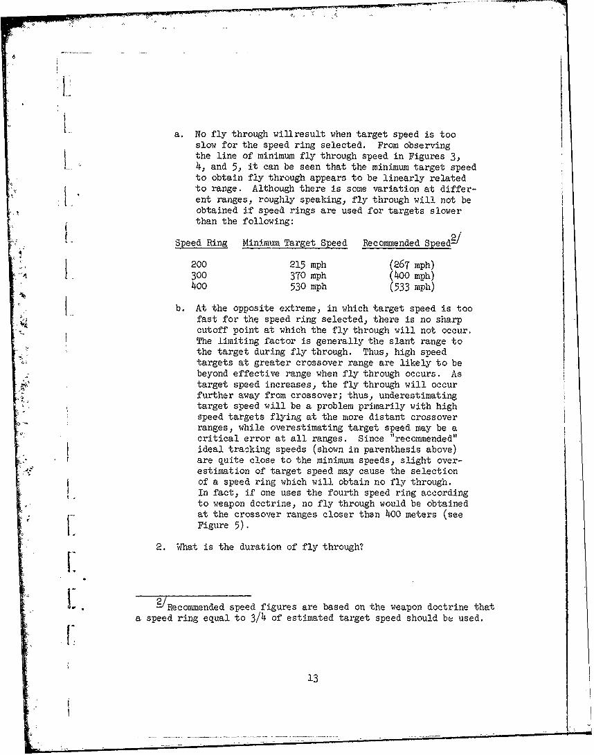
a. No fly through willresult when target speed is too
slow for the speed ring selected. From observingthe line of minimum fly through speed in Figures 3,
L. 4, and 5, it can be seen that the minimum target speedto obtain fly through appears to be linearly relatedto range. Although there is some variation at differ-ent ranges, roughly speaking, fly through will not beobtained if speed rings are used for targets slower
-than the following:
Speed Ring Minimum Target Speed Recommended Speed - /
200 215 mph (267 mph)4 300 370 mph (400 mph)
400 530 mph (533 mph)
C b. At the opposite extreme, in which target speed is too
fast for thq speed ring selected, there is no sharpcutoff point at which the fly through will not occur.The limiting factor is generally the slant range tothe target during fly through. Thus, high speedtargets at greater crossover range are likely to bebeyond effective range when fly through occurs. Astarget speed increases, the fly through will occurfurther away from crossover; thus, underestimatingtarget speed will be a problem primarily with highspeed targets flying at the more distant crossoverranges, while overestimating target speed may be acritical error at all ranges. Since "recommended"ideal trackin& speeds (shown in parenthesis above)are quite close to the minimum speeds, slight over-estimation of target speed may cause the selectionof a speed ring which will obtain no fly through.In fact, if one uses the fourth speed ring accordingto weapon doctrine, no fly through would be obtainedat the crossover ranges closer then 400 meters (see
I Figure 5).
2. What is the duration of fly through?
sa speed ring equal to 3/4 of estimated target speed should be used.
13
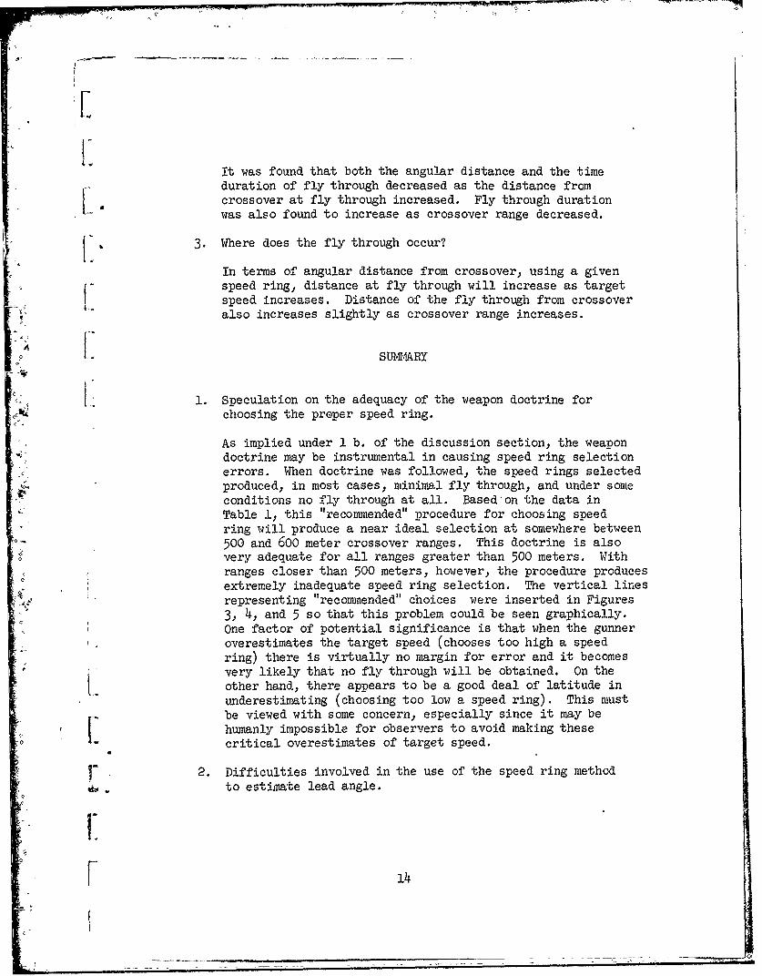
It was found that both the angular distance and the timeduration of fly through decreased as the distance from
ocrossover at fly through increased. Fly through durationwas also found to increase as crossover range decreased.
V, 3. Where does the fly through occur?
In terms of angular distance from crossover, using a givenspeed ring, distance at fly through will increase as targetspeed increases. Distance of the fly through from crossover
also increases slightly as crossover range increases.
4 , SUMARY
V 1. Speculation on the adequacy of the weapon doctrine forchoosing the proper speed ring.
As implied under 1 b. of the discussion section, the weapondoctrine may be instrumental in causing speed ring selectionerrors. When doctrine was followed, the speed rings selected
produced, in most cases, minimal fly through, and under someconditions no fly through at all. Based on the data inTable 1, this "recommended" procedure for choosing speedring will produce a near ideal selection at somewhere between500 and 600 meter crossover ranges. This doctrine is alsovery adequate for all ranges greater than 500 meters. Withranges closer than 500 meters, however. the procedure produces
- .extremely inadequate speed ring selection. The vertical linesrepresenting "recommended" choices were inserted in Figures3, 4, and 5 so that this problem could be seen graphically.One factor of potential significance is that when the gunneroverestimates the target speed (chooses too high a speedring) there is virtually no margin for error and it becomesvery likely that no fly through will be obtained. On theother hand, there appears to be a good deal of latitude in
underestimating (choosing too low a speed ring). This mustbe viewed with some concern, especially since it may be
1| humanly impossible for observers to avoid making thesecritical overestimates of target speed.
r 2. Difficulties involved in the use of the speed ring method
to estiirmte lead angle.
F 14
! xi
The findings suggest that at least two general problems
exist in using the speed ring sight, First, since anr. inter-action between target speed and target range affects
1 selection of the proper speed ring, it may not be possible toformulate a rule for speed ring selection which is simpleenough to be usable, yet at the same time comprehensiveenough to apply to the wide variety of potential engagementconditions. Second, the prediczed duration of fly through
S will be relatively small under most conditions, and thegunner will have no way of knowing where along the targetpath the predicted fly through is supposed to occur. Thegunner will not be able to coordinate his tracking and
Sfiring with the fly through pattern which controls his hitprobability. A consideration of the problems involved inusing the speed ring sight would suggest that alternativemethods of adjusting lead angle should be sought and
L implemented whenever possible.
[1VV
' 15
fI