tombarra inspection report dated 23/3/2011€¦ · · 2014-12-01the winch wire broke and the...
TRANSCRIPT

Annex A
Tombarra inspection report dated 23/3/2011


Page 1 of 8
Norsafe Watercraft Hellas S.A.
7th Kilometre of the Old National RoadThebes to Chalkis
32200, Thebes, GREECE
Tel.: +30 2262 022 441 /Fax.: +30 2262 029 075
www.norsafe.com
INSPECTION REPORT
Vessel: M/V Tombara
Yard: N/a Supplier/Subcontractor: USH Product/Service: Rescue boat inspection Owner: Wilhelmsen Lines Date: 23rd of March 2011 Location: Bristol Royal Docks
Norsafe WCH rep: , Other persons attending:
, Inspector of MAIB
, C-F Spencer & Co
,Vessel Manager, Wilhelmsen Lines
, MCGA, Surveyor in charge
Boat Type: WHFRB 650 outboard rubber fender version Serial Number: 124 Build date: 06/06 Hook type: N/A lifting frame only
Introduction:
A fatal accident took place on board MV Tombara. The winch wire broke and the rescue boat fell to the sea with 3 persons. One of them died. We were asked from MAIB accident investigator to attend Royal Portbury Docks, Bristol, in order provide technical guidance on aspects of the investigation concerning the rescue boat. Inspection:
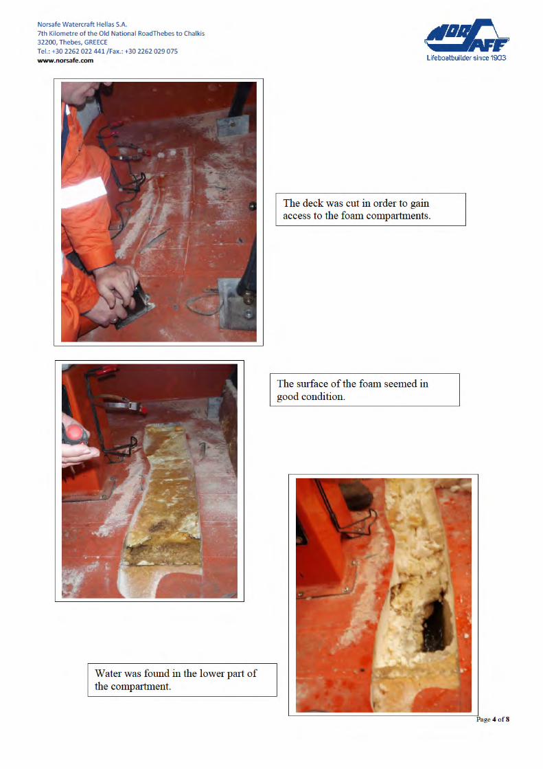
The boat was weighted with full equipment and fuel and the weight was found to be 1450 Kgs. The deck GRP was cut in a vertical axis in the fore, middle and aft in order to see the condition of the foam compartmets. The upper surface of the foam was in good condition but when we cut deeper we found water and the foam had shrunk and had a dark color. This observation was mainly in the middle and aft sections. Then we drilled holes underneath the hull to access all compartments. From 15 compartments drilled, water was found in 14 of them. Most of the water was found in the aft sections. Pieces of foam and samples of water was collected for examination. The water seemed to be salty sea water. Several areas of possible water ingress were found.
- Water could have penetrated after the boat fell in the sea from the damaged area in the bow. - The starboard side of the hull was found repaired in a bad manner and osmosis had appeared. This
could also be a possible area of water penetration in all compartments. - The inspection hatches of the crew seating bench were destroyed. - The screws around the helmsman’s console could also allow water to penetrate under the deck.
Silicone was found on top of the manufacturer’s sikaflex used to protect water penetration. - Foaming application holes on the deck floor were found to be needing service. Water can penetrate
through these holes if remains for a long time on the deck. - Water can also penetrate from the lifting frame both from the deck or from the hull.
Conclusion:
We were informed that the root cause of the accident might be a limit switch on the davit that failed to work properly and thus damaged the wire rope. Apart from that, the boat was weighed after the accident

Page 2 of 8
Norsafe Watercraft Hellas S.A.
7th Kilometre of the Old National RoadThebes to Chalkis
32200, Thebes, GREECE
Tel.: +30 2262 022 441 /Fax.: +30 2262 029 075
www.norsafe.com
and found overweighed. MAIB and the vessel owners are concerned that the weight of the boat is higher than it should be when initially supplied. The boat weight before dispatch from the factory was 980Kgs without full equipment and fuel. That means the boat at the present time is approximately 400 Kgs overweight. No Norsafe Watercraft personnel have performed annual or other kind of service onboard. The reason of the extra weight seems to be the sea water trapped inside the foam compartments. In order to determine the reason that water penetrated to these compartments, destroying the foam and when this happened we need to weigh and inspect other similar boats on board vessels of the same fleet. Pictures follow.


Annex B
Fast rescue boat trials and analysis report


DOCUMENT CONTROL SHEET
FAST RESCUE BOAT TRIALS AND ANALYSIS
FOR
MARINE ACCIDENT INVESTIGATION BRANCH
REPORT
02 2 Dec 2011 Incorporating MAIB comments CC BC
01 8 Nov 2011 Incorporating MAIB comments CC BC
Rev. Date Reason for Issue Author Check Client
LG Doc. Title Fast Rescue Boat Trials Report
LG Ref No. S101
Client Doc Title
Client Ref No. MAIB4/3/97
LG pro-forma Technical Report

Our ref: S101 MAIB FAST RESCUE BOAT TRIALS AND ANALYSIS
EXECUTIVE SUMMARY
Longitude Engineering was appointed by the Marine Accident Investigation Branch (MAIB) to undertake a series of trials on a SOLAS Fast Rescue Boat (FRB) as part of an on-going investigation into the Tombarra Rescue Boat (RB) accident. During the investigation it was found that the FRB was significantly overweight due to water ingress. A second FRB sister craft to the Tombarra RB was donated for trials to the MAIB by a ro-ro ferry operator, which on receipt was also found to be overweight due to water ingress. The aims of the FRB trials work were to determine the effect of additional boat weight on compliance with SOLAS Type Approval requirements, and to analyse the structural integrity of the craft. The impact of trials findings on the craft’s ability to carry out its role as a Fast Rescue Craft was assessed. Although commonality of results with other craft in the fleet could not be directly appraised, potentially generic issues were investigated alongside specific findings. A series of trials were carried out on the craft. On the water the vessel was subjected to standard SOLAS Type Approval tests such as Freeboard, Towing, Operation, Self-bailing and Righting. The vessel was then cut apart in a logical manner to assess the structural integrity. Type Approval tests showed that the additional weight due to water ingress into the hull had a significant effect on operability of the craft. Speed was heavily reduced from the required 20 knots to less than 8 knots, albeit with the original engine provided with the vessel. If swamped it was shown that the vessel would not self-drain, and due to reduced freeboard swamping was increasingly likely. Although freeboard was reduced it was still above the SOLAS minimum, however this puts the engine very low in the water, potentially compromising its reliability. Other small details also combined with reduced freeboard to produce potentially hazardous conditions. The vessel’s ability to self-right, tow and be towed was not affected by the additional weight and she still appeared to handle safely when being operated. The structural integrity of the hull shell and deck appeared to be good externally however there were signs of gel coat cracking in the topsides on the starboard side. The internal grillage of stiffeners was showing significant damage, considered likely to have been caused by side impact during launch and recovery. Side impact damage was also found elsewhere on the craft. It was likely that the damage may have been exacerbated by lifting operations with the boat in an overweight condition as there was evidence of cracking in the longitudinal stiffeners in way of the aft lifting points. This damage potentially compromised the vessel’s ability to accept lifting loads. Lifting factors of safety were further reduced through the vessel being overweight and due to the nature of the design such a failure was hidden from any maintenance activity. The buoyant foam was on the whole in good condition, with only a small amount of water retention in the boundary layer. The remainder of the foam was dry. Due to the manufacturing process, voids have been formed at the edges of each space that may constitute approximately 10% of calculated buoyant volume. It is suggested that in future some permeability factor be applied to designers’ buoyant volume calculations. The deck has been shown to leak gradually and the design allows significant amounts of water to accumulate both in the aft void and in voids formed on the edge of foam filled spaces. There was a gap under the deck that allows water to move freely in the boat. In addition, the damage to the open stiffener grillage in this craft allowed further flooding to take place. Water retained by the craft in the open stiffener structure and foam edge voids could not be drained. In this case the craft was found to be 80% overweight (800 litres trapped in a 1000kg craft). The key issues were water ingress and the ability to drain the water from the hull during its service life. The vessel was removed from its ship in the condition in which it was tested and as such the MAIB trials have been highly representative of an overweight in-service craft. It was considered that the assessed craft in this condition was not suitable for safe use as a Fast Rescue Boat.

Our ref: S101 MAIB FAST RESCUE BOAT TRIALS AND ANALYSIS
REVISION HISTORY
Revision Number
Revision Purpose Description of Changes Pages Affected
01 Including MAIB comments Multiple All
02 Including MAIB comments See MAIB list 28-11-11 3, 5, 39, 40, 42

Our ref: S101 MAIB FAST RESCUE BOAT TRIALS AND ANALYSIS
TABLE OF CONTENTS
1 INTRODUCTION
2 VESSEL DETAILS
3 TRIALS INTENT
4 TRIALS METHODOLOGY
5 PREPARATORY WORK 5.1 Determine trials location 5.2 Preliminary Test vessel survey 5.3 Vessel weight on receipt 5.4 Vessel weight for trials 5.5 Vessel preparation for trials 5.6 SOLAS trials risk assessment
6 SOLAS TRIALS RESULTS 6.1 Vessel weight 6.2 Freeboard test 6.3 Towed test 6.4 Bollard pull test 6.5 Operation tests – speed and manoeuvring 6.6 Self bailing test 6.7 Righting test
7 SOLAS TRIALS INTERPRETATION 7.1 Rescue Boat Trials (as opposed to Fast Rescue Boat)
8 STRUCTURAL ASSESSMENT TRIALS 8.1 Determine construction method 8.2 Deck water tightness test 8.3 Drain and measure water 8.4 Hull to deck joint assessment 8.5 Remove foredeck, inspect deck fixings and top layer of buoyant foam 8.6 Full transverse cut in way of console 8.7 Aft hull section cuts 8.8 Mid section examination 8.9 Side damage investigation 8.10 Lift point investigation
9 TOMBARRA RESCUE BOAT 9.1 Preliminary Tombarra survey 9.2 Secondary Tombarra survey
10 STRUCTURAL ASSESSMENT RESULTS 10.1 Structural integrity 10.2 Buoyancy foam 10.3 Water ingress and weight growth
11 CONCLUSIONS
12 RECOMMENDATIONS APPENDICES A WHFRB6.5 Drawings B WHFRB6.5 Specification C Trials Locations D SOLAS Trials Risk Assessment E IMO MSC Circ 980 Add2 F Original WHFRB6.5 SOLAS approval documents G Photographic Record of Trials - Disk

Our ref: S101 MAIB FAST RESCUE BOAT TRIALS AND ANALYSIS
LIST OF FIGURES
Figure 1. WHFRB 6.5 Figure 2. General Arrangement Figure 3. Deck bungs for water introduction Figure 4. Vessel being weighed on load cell Figure 5. Controls conduit allows flooding Figure 6. Freeboard trial Figure 7. Engine immersion during freeboard trial Figure 8. Towed test Figure 9. Bollard pull test Figure 10. Vessel under way fully loaded Figure 11. Vessel doing turning circle trial Figure 12. Self draining test Figure 13. Righting test Figure 14. Water drained from void spaces Figure 15. Water drained from stiffener grillage Figure 16. Draining of trapped water Figure 17. Hull to deck joint Figure 18. Foredeck removal Figure 19. Deck plug Figure 20. Transverse cut in way of console and stiffener detail Figure 21. Foam voids in sides of spaces Figure 22. Foam boundary condition Figure 23. Stiffener to hull over-bonded joints Figure 24. Aft hull section cut Figure 25. Aft hull stiffener inspection cut Figure 26. Representative damage to stiffener structure in aft transverse stiffener Figure 27. Mid section deck removed Figure 28. Representative gap between deck and foam Figure 29. Mid section primary structure Figure 30. Mid section showing crack in way of the transverse and the longitudinal stiffener Figure 31. Damage to side stiffener – example failure Figure 32. Hull gel coat crazing Figure 33. Side shell damage repair Figure 34. Summary of damage locations

Our ref: S101 MAIB FAST RESCUE BOAT TRIALS AND ANALYSIS
1. INTRODUCTION Longitude Engineering was appointed by the Marine Accident Investigation Branch (MAIB) to undertake a series of trials on a SOLAS Fast Rescue Boat (FRB) as part of an on-going investigation into the Tombarra RB accident. During the investigation it was found that the FRB was significantly overweight due to water ingress. A second FRB sister craft to the Tombarra RB was donated to the MAIB by a ro-ro ferry operator, who had discovered the FRB to be substantially overweight and had removed it from service. Trials were to be carried out on the vessel in this representative condition. 2. VESSEL DETAILS The vessel being assessed was as follows:
• Watercraft Hellas 6.5m Fast Rescue Boat (WHFRB6.50) • FRB No5 • Previously approved as a Rigid Fast Rescue Boat under SOLAS by Bureau Veritas • Approval TAC/10241/AO/EC, Date 15-9-00, Wheel mark NB0062/00
Figure 1. WHFRB 6.5

Our ref: S101 MAIB FAST RESCUE BOAT TRIALS AND ANALYSIS
Figure 2. General Arrangement See Appendix A – WHFRB6.5 Drawings and Appendix B – WHFRB6.5 Specification for further details. 3. TRIALS INTENT The primary aims of the FRB trials work were to assess the following:
• Determine the effect of additional boat weight resulting from water ingress on compliance with SOLAS Type Approval requirements
• Determine primary structural integrity of craft • Assess integrity of buoyant volumes • Assess foam condition and permeability • Assess impact of findings on the craft’s ability to carry out its roles as a both a Fast
Rescue Boat and to an extent as a Rescue Boat. • Provide documented record of the structure of a vessel of this age.

Our ref: S101 MAIB FAST RESCUE BOAT TRIALS AND ANALYSIS
4. TRIALS METHODOLOGY In order to address the trials intent, the following trials methodology was determined in collaboration with the MAIB:
• Preparatory work o Determine trials location for Trial FRB o Preliminary Trial FRB survey o Determine vessel trials weight o Prepare vessel for trials o SOLAS trials risk assessment
• SOLAS trials o Weigh craft (repeated at intervals) o Freeboard test o Towed test o Bollard pull test o Operation tests - speed and manoeuvring o Self bailing test o Righting test
• Structural assessment trials o Determine construction method o Deck water tightness test o Drain and measure trapped water in void spaces o Hull to deck joint assessment o Remove foredeck, inspect deck fixings and buoyancy foam o Full transverse cut in way of console o Aft hull section cuts o Mid section examination o Side damage investigation o Lift point investigation
• Survey Tombarra Rescue Boat and compare findings 5. PREPARATORY WORK 5.1 Determine trials location An assessment was carried out possible locations for carrying out the Trial FRB trials. It was decided that the work be carried out in partnership with a boat yard in County Antrim, Northern Ireland. On the water trials were conducted at a local slipway and quay. Further details are provided in Appendix C. 5.2 Preliminary Test vessel survey A preliminary survey was carried out of the Trial FRB, with the following observations:
• Vessel appeared watertight and structurally sound enough to carry out trials • Engine supplied was original to the vessel. Engine operated but was suspected not to be
achieving equivalent power to a new engine. • Steering system was missing, and it was decided that employing the emergency steering
tiller would suffice for the trials. • Batteries were on board and were functioning • Righting frame was intact • Transom joint showed cracking but was considered adequate for trials purposes • 3 of the 4 hull lift point connections were slowly but persistently leaking, indicating trapped
water
Our ref: S101 MAIB FAST RESCUE BOAT TRIALS AND ANALYSIS
5.3 Vessel weight on receipt The following information was received from the MAIB with the vessel:
• Vessel weight was recorded as 1800kg, including 110kg engine, 39kg fuel and 27kg SOLAS kit, but not including crew.
• Approximately 550 litres was drained from the hull through the aft bung At build the vessel weighed 1000kg, including engine, fuel and SOLAS kit, but not including crew. Therefore the vessel was 800kg or 80% overweight when taken out of service. The first aim of the MAIB trial was to bring the boat back to the weight recorded on removal from service, such that it was being tested in a realistic condition. The vessel was weighed (using a calibrated weigh bridge) on arrival at the trials location:
• Vessel weight = 1040kg, but with no engine, fuel or SOLAS kit
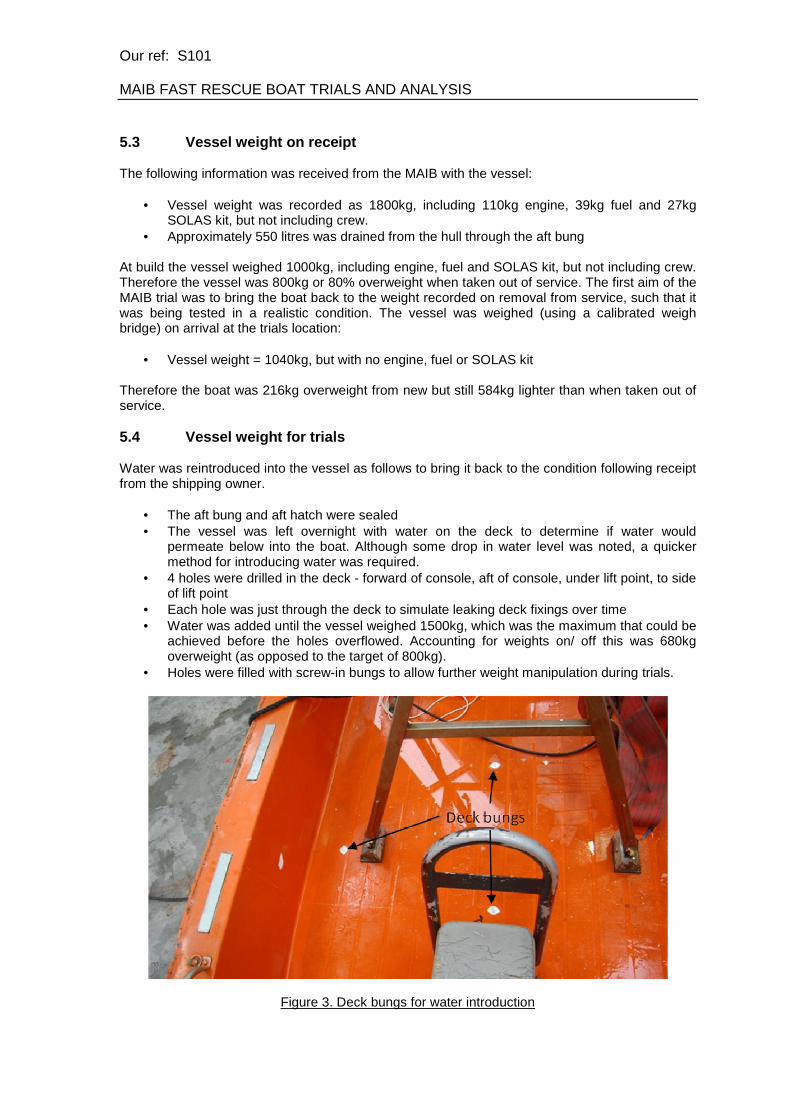
Therefore the boat was 216kg overweight from new but still 584kg lighter than when taken out of service. 5.4 Vessel weight for trials Water was reintroduced into the vessel as follows to bring it back to the condition following receipt from the shipping owner.
• The aft bung and aft hatch were sealed • The vessel was left overnight with water on the deck to determine if water would
permeate below into the boat. Although some drop in water level was noted, a quicker method for introducing water was required.
• 4 holes were drilled in the deck - forward of console, aft of console, under lift point, to side of lift point
• Each hole was just through the deck to simulate leaking deck fixings over time • Water was added until the vessel weighed 1500kg, which was the maximum that could be
achieved before the holes overflowed. Accounting for weights on/ off this was 680kg overweight (as opposed to the target of 800kg).
• Holes were filled with screw-in bungs to allow further weight manipulation during trials.
Figure 3. Deck bungs for water introduction

Our ref: S101 MAIB FAST RESCUE BOAT TRIALS AND ANALYSIS
This exercise demonstrated the following:
• If water was able to penetrate the deck it could move throughout the vessel in the gap between the deck and foam underneath
• The aft hatch needed to be closed to maximise the amount of water in the aft void space and therefore in the boat as a whole. As the aft void floods, dependant on the trim angle, this allows significant water retention in the open side gunwale void spaces.
• Trials would be able to be carried out at a weight that was similar to that recorded when the FRB was taken out of service.
5.5 Vessel preparation for trials In other respects the vessel was prepared for trials:
• Engine was fitted after being brought up to an operational condition. • Throttle fitted • Lifeline fixing holes sealed up • Ballast organised to simulate full fuel load and SOLAS kit
5.6 SOLAS trials risk assessment In advance of the trials a risk assessment was carried out, attended by the MAIB, Longitude Engineering, Red Bay Boats and other trials personnel. Further details are provided in Appendix D. 6. SOLAS TRIALS RESULTS SOLAS trials results are detailed in the following sections. In each case the following information was determined, producing in totality the SOLAS compliance matrix for the craft:
• Trial activities • Type approval rule requirement • Previous result • Current result • Additional relevant information
Trial requirements were taken from:
• IMO MSC Circ 980 Add2 Standardised Life-Saving Appliance Evaluation and Test Report Forms, 13th February 2001. This is attached to this report as Appendix E.
Original results were taken from:
• Water Craft Hellas SA WHFRB6.50 Fast Rescue Boat (Rigid) Evaluation and Test Report. This is attached to this report as Appendix F
• Carried out by Bureau Veritas, 19-10-2000 • Stated as WHFRB 6.50 Rubber Fender Version • Supplemented by further Righting and Operational tests on GRP Righting Frame
Version. Carried out by Bureau Veritas, 27-12-2004. This is attached to this report included in Appendix F.
Weather conditions for all trials were calm (Force 0-1) and were carried out in sheltered conditions. Trials were witnessed by the MAIB and were carried out on the following dates:

Our ref: S101 MAIB FAST RESCUE BOAT TRIALS AND ANALYSIS
• 10th October 2011 – Weighing, Towed test, Bollard Pull, Speed, Manoeuvrability • 11th October 2011 – Weighing, Freeboard; Self-draining, Righting
Operational trials were carried out using the emergency steering, and as such the forward crewman was in a position where the throttle could be used and visual contact maintained with the helmsman. He was not seated in the coxswain’s normal seat. Longitudinal centres of gravity were considered representative of the design fully loaded condition.

Our ref: S101 MAIB FAST RESCUE BOAT TRIALS AND ANALYSIS
6.1 Vessel weight A critical component of the SOLAS trials was to clearly understand the weight of the vessel at key points in the trials programme. As such the vessel was weighed throughout, as detailed in the following report. SOLAS requirement – Test 5.5.0.1, LSA Code 4.4, 5.1, MSC.81(70) 1/7.1.9
Result – Weight at different stages in the trials 1. Weight fully fitted but ex-crew, prior to Towed test/ Bollard pull/ Operational tests, 1797kg 2. Weight fully fitted but ex-crew, following Towed test/ Bollard pull/ Operational tests, 1667kg 3. Weight fully fitted but ex-crew, prior to Freeboard test/ Self-draining/ Righting, 1740kg 4. Weight prior to 3rd Righting trial, engine and fuel off, 1650kg. 5. Weight prior to 4th Righting trial, engine and fuel off, aft compartment drained of water, 1400kg 6. Weight following full drill and drain, prior to deconstruction, 925kg
Previous result Design weight, unloaded boat with outboard engine = 935kg Design weight, loose equipment = 26.5kg Design weight, fuel = 38.5kg Calculated weight fully fitted but ex-crew = 1000kg Persons = 450kg Calculated load weight, fully equipped with 6 persons = 1450kg No comments or observations
Additional information
• All weighed values generated by calibrated load cell o AST Equipment 5 tonne Accuway TM Loadcell o S/N TM848 o Cert. No. M13610 o Calibration device AJT01, Cert no. T7629, 29-11-2010
• Some stated weights have been corrected into like-for-like comparison through simple weights on/off calculations for fuel and SOLAS kit.
• Although weights varied throughout the trials due to gaining or losing trapped water, the intent of testing a representative overweight boat was maintained within a reasonable weight margin.

Our ref: S101 MAIB FAST RESCUE BOAT TRIALS AND ANALYSIS
Figure 4. Vessel being weighed on load cell

Our ref: S101 MAIB FAST RESCUE BOAT TRIALS AND ANALYSIS
6.2 Freeboard test SOLAS requirement – Test 5.5.2.2, LSA Code 4. 4.5, MSC.81(70) 1/6.8.4-.5
• The rescue boat with its engine should be loaded with a mass equal to that of all the equipment.
• One half of the number of persons for which the rescue boat is to be approved should be seated in a proper seating position on one side of the centreline. The freeboard should then be measured on the low side. The freeboard of the boat should be taken in the loading condition with all equipment, engine and fuel, or equivalent mass positioned to represent engine and fuel.
• This test should be considered successful, if the measured freeboard, on the low side, is not less than 1.5% of the rescue boat's length or 100 mm, whichever is greater.
Result Measured freeboard = 150mm 1.5% of boats length = 102mm Passed with conduit blocked – see note below
Previous result Measured freeboard = 300mm 1.5% of boats length = 102mm Passed
Additional information
• Trial was initially carried out with an open conduit for control cables. This resulted in flooding into the boat that did not show signs of stopping, and precluded a stable freeboard reading. Trial was terminated for safety reasons and the conduit was blocked up to prevent flooding into boat. This was the case for the remainder of the trials.
• The boat weighed 1740kg prior to trial, including engine and compensating ballast for fuel/ SOLAS kit. Crew not included in 1740kg. Craft was therefore 740kg heavier than that reported in the original BV evaluation and test report.
• Freeboard was measured at the aft transom corner, which was the lowest point. Corresponding freeboard in line with the lift point was 260mm and at the stem was 620mm
• In a heeled condition the transom in way of the engine was 60mm below water. • Crew weights for the trial were in excess of historic requirement of 75kg each and on
average were closer to current SOLAS figure of 82.5kg. • Crew seated positions were on the deck, with the stretcher position also on the deck. • Freeboard trials were carried out twice. Results were taken from the more accurate trial
on 12-10-11. • In a static fully loaded condition with crew in normal seated positions, freeboard was:
o Transom P 300mm o Transom S 340mm o Transom i.w.o. engine 40mm under water o Stem 670mm

Our ref: S101 MAIB FAST RESCUE BOAT TRIALS AND ANALYSIS
Figure 5. Controls conduit allowed flooding
Figure 6. Freeboard trial

Our ref: S101 MAIB FAST RESCUE BOAT TRIALS AND ANALYSIS
Figure 7. Engine immersion during freeboard trial

Our ref: S101 MAIB FAST RESCUE BOAT TRIALS AND ANALYSIS
6.3 Towed test SOLAS requirement – Test 5.5.6.1, LSA Code 4.4.1.3.2, 4.4.7.7, MSC.81(70) 1/6.11.1
• It should be demonstrated that the fully equipped rescue boat, loaded with a properly distributed mass equal to the mass of the number of persons for which it is to be approved, can be towed at a speed of not less than 5 knots in calm water and on an even keel using the rescue boat's painter securing device.
• The rescue boat should not exhibit unsafe or unstable characteristics. • There should be no damage to the rescue boat or its equipment as a result of this test.
Result Passed
Previous result Passed Comment: Test was carried out with a high speed pleasure boat
Additional informat ion
• Trial was carried out in a fully loaded condition with 2 crew, and ballast for 4 remaining crew, fuel and SOLAS kit.
• Weight fully loaded but ex-crew, prior to Towed test = 1797kg • Tow was carried out at 5.1 knots • Dynamic stability when on tow was tested through progressive movement of crew. • Boat was found to be stable at all times. • Original painter and securing device were not fitted and as such could not be tested.
Figure 8. Towed test

Our ref: S101 MAIB FAST RESCUE BOAT TRIALS AND ANALYSIS
6.4 Bollard pull test SOLAS requirement – Test 5.5.5.1, LSA Code 4.4. 6.8, 5.1.1.7, MSC.81(70) 1/7.1.2
• The rescue boat should be loaded with weights equal to the mass of its equipment and the number of persons for which the rescue boat is to be approved. It should be demonstrated that the rescue boat can tow a 25 person life raft, as a minimum, loaded with the number of persons for which it is to be approved and its equipment at speed of 2 knots in calm water.
• The largest size of fully loaded life raft which the rescue boat can tow at a speed of at least 2 knots should be determined. Alternatively, determine the maximum towing force of the rescue boat by securing the fitting designated for towing other craft to a stationary object by a tow rope fitted with a means to measure bollard pull. The engine should be operated ahead at full speed for a period of at least 2 min. and the maximum force recorded. (For rescue boats equipped with outboard motor, raft towing or bollard pull trials may be carried out with engines of various powers to assess the rescue boat’s performance.)
• There should be no damage to the towing fitting or its supporting structure.
Result Fitted with Yamaha 60 engine Propeller Pitch Not recorded Propeller Diameter Approx.11.5” Bollard pull 265kg (2.60kN) No obvious damage Passed
Previous result Fitted with Yamaha 60 engine Propeller Pitch 17” Propeller Diameter 13.25” Bollard pull 350kg (3.43kN) No obvious damage Passed
Additional information
• Trial was carried out in a fully loaded condition with 2 crew, and ballast for 4 remaining crew, fuel and SOLAS kit.
• Weight fully loaded but ex-crew, prior to Bollard Pull test = 1797kg • The engine immersion during tow was a concern, although the engine did not fail. • The engine was fitted with a propeller guard during the trials. • Although standard to the boat, the engine was not considered to be operating optimally,
estimated at ¾ power capacity. • The propeller appears to be different to that originally fitted, with a smaller diameter and
possibly different pitch. The propeller was also showing signs of damage. • The boat was found to be stable during trial. • RFD Beaufort has stated that in a calm sea state a Surviva Mk4 25DL life raft, with
2119kg total load in raft, and sea anchor streamed, has a drag of 1.81kN at 2 knots and 1.64kN at 3 knots.

Our ref: S101 MAIB FAST RESCUE BOAT TRIALS AND ANALYSIS
Figure 9. Bollard pull test

Our ref: S101 MAIB FAST RESCUE BOAT TRIALS AND ANALYSIS
6.5 Operation tests – speed and manoeuvring SOLAS requirement – Test 5.5.5.2, LSA Code MSC/ Circ 809, Annex 4.1.4 MSC.81(70) 1/7.1.6, 7.4.2.1-.2
• The rescue boat should be loaded with weights equal to the mass of its equipment and the number of persons for which the rescue boat is to be approved.
• The engine should be started and the boat manoeuvred to demonstrate satisfactory operation.
• The rescue boat should be run at a speed of not less than 8 knots with a full complement of persons and equipment and 20 knots with a crew of 3 persons.
• The boat should operate satisfactorily throughout the operation.
Result Fitted with Yamaha 60 engine Propeller Pitch Not recorded Propeller Diameter Approx.11.5” Boat speed fully loaded = 7.34 knots Boat speed with 3 crew = 7.73 knots Failed
Previous result (2004) Fitted with Yamaha 60 engine Propeller Pitch 17” Propeller Diameter 13.25” Boat speed fully loaded = 8 knots @ 3000rpm Boat speed with 3 crew = 20 knots @ 4600rpm Passed
Additional information
• Fuel consumption trials normally associated with test 5.5.5.2 were not carried out. • Tests on different engines were not carried out. • Trials were not run for the standard 4 hours. • Trial was first carried out in a fully loaded condition with 2 crew, and ballast for 4
remaining crew, fuel and SOLAS kit. Ballast was then removed for 3-man operations. • Weight fully loaded but ex-crew, prior to Operational test = 1797kg • Speed results were achieved over a minimum of two 500m runs (with and against tide)
using GPS speed measurement. • Engine immersion during operation was a concern, although the engine did not fail. • Engine was fitted with a propeller guard during the trials although this was found to be
damaged part way through the trials. • Speed results were taken with the repaired propeller guard • Although standard to the boat, the engine was not considered to be operating optimally,
estimated at ¾ power capacity. • Propeller appears to be different to that originally fitted, with a smaller diameter and
possibly different pitch. The propeller was also showing signs of damage. • Progressive handling trials were carried out • Turning circles were carried out with the FRB found to be stable during the manoeuvres. • Trials were carried out in the 1-2ft wake of the 11m safety boat. The FRB appeared to be
dynamically stable during this test. • Steering remained positive during trials • Emergency steering was used successfully

Our ref: S101 MAIB FAST RESCUE BOAT TRIALS AND ANALYSIS
Figure 10. Vessel under way fully loaded (using emergency steering)
Figure 11. Vessel doing turning circle trial (using emergency steering)

Our ref: S101 MAIB FAST RESCUE BOAT TRIALS AND ANALYSIS
6.6 Self bailing test SOLAS requirement – Test 5.5.1.2, LSA Code 5.1.4.6
• Automatically self-bailing or capable of rapidly clearing water
Result 10 minutes to drain to an average 167mm depth of water on the deck in the aft area. Draining did not appear to be continuing. Failed
Previous result Passed No comment
Additional information
• Trial was carried out in a fully loaded condition with ballast for 6 crew, fuel and SOLAS kit. • A dummy engine was fitted, with added weights fitted to match the 110kg original
outboard engine weight. • Boat weighed at 1740kg prior to trial, including engine and compensating ballast for fuel/
SOLAS kit. Crew not included in 1740kg. Craft was therefore 740kg heavier than that reported in the original BV evaluation and test report.
• Trouser drains were tied up • Boat was filled up with water using a fire pump • Trouser drains were released and the time taken to drain was measured • At 10 minutes:
o Freeboard aft S = 240mm o Freeboard aft P = 300mm o Water depth inside boat at aft end S = 205mm o Water depth inside boat at aft end P = 130mm o Draining slowed to imperceptible
• Water surged to the Starboard side during swamping • The boat appeared to remain stable when swamped, but for safety reasons this was not
further tested by personnel moving in boat
Figure 12. Self draining test

Our ref: S101 MAIB FAST RESCUE BOAT TRIALS AND ANALYSIS
6.7 Righting test SOLAS requirement – Test 5.5.2.3, MSC.81(70) 1/7.1.7
• It should be demonstrated that both with and without engine and fuel or an equivalent mass in place of the engine and fuel tank, the rescue boat is capable of being righted by not more than two persons if it is inverted on the water.
Result Vessel self-righted without intervention both with and without engine/fuel Passed
Previous result Passed with engine and fuel Passed without engine and fuel No comment
Additional information
• Four righting trials were carried out: o 1) Boat complete with engine and fuel, 1st o 2) Boat complete with engine and fuel, 2nd o 3) Boat without engine or fuel o 4) Boat without engine and fuel, and after draining the hull of 250 litres
• Boat weighed at 1740kg prior to Trial 1 (and assumed the same for Trial 2), including engine and compensating ballast for fuel/ SOLAS kit. Crew not included in 1740kg. Crew weights were not added to boat for righting trials. Craft was therefore 740kg heavier than that reported in the original BV evaluation and test report.
• Boat weighed at 1650kg prior to Trial 3, without engine or fuel but with compensating ballast for SOLAS kit.
• Boat weighed at 1400kg prior to Trial 4, without engine or fuel but with compensating ballast for SOLAS kit. 250 litres had been drained out of the hull prior to weighing.
• In all cases the vessel righted without intervention. • A short period of inverted stability was noted, however this may have been due to the
calm conditions. It was considered that should this have occurred, then a small amount of intervention would have righted the vessel.
• The trial was carried out using the RNLI method of a crane with a strop led under the boat and attached to the lift point.
• Load was logged on the crane at all points in the capsize cycle up to approximately 170 degrees, implying a positive GZ curve. Crane load reached a maximum of 700kg during the inversion.
• Time to right from 180 degrees was approximately 12 seconds. • Following righting the vessel was full of water and required forced drainage. • Self-righting boxes were dry following trials. • No deformation or damage was noted on the lift frame (from the inversion) or on the
righting frame (from the recovery).

Our ref: S101 MAIB FAST RESCUE BOAT TRIALS AND ANALYSIS
Figure 13. Righting test 7. SOLAS TRIALS INTERPRETATION Through carrying out the listed Type Approval tests the effect of additional boat weight on compliance with SOLAS requirements has been determined. Trials results are summarised in the following compliance table: Test Result Comment Freeboard Fail - conduit open
Pass - conduit shut
Freeboard in a heeled condition was halved from 300mm to 150mm Although the vessel still passed the 102mm heeled freeboard criteria, the engine was too close to the water, with the transom mount immersed. Engine failure due to immersion was a real possibility. The standard controls conduit design compromised freeboard to a potentially dangerous extent, allowing the vessel to flood and also possibly endangering the engine operability. Blocking the conduit for the trials may therefore have been considered unrealistic, but it was considered unsafe to do otherwise.
Towed test Pass The vessel could be safely towed. Bollard pull Pass Although bollard pull was reduced it was still considered
acceptable Operation Fail The additional trapped weight prevented the vessel from
achieving its necessary 20 knots speed. The significant shortfall down to under 8 knots heavily compromises its functionality as a FRB. It was possible that a new engine or propeller may have improved this to an extent. Changes through life may have a pronounced effect on functionality.
Self bailing Fail If flooded (either by the conduit tube or by a wave), the vessel drained only slowly and even then only up to a point.
Righting Pass The ability to right did not appear to be affected by the additional weight.

Our ref: S101 MAIB FAST RESCUE BOAT TRIALS AND ANALYSIS
7.1 Rescue Boat trials (as opposed to Fast Rescue Boat) The SOLAS trials have been carried out against the Fast Rescue Boat (Rigid) test requirements, as this reflects the original approval for the vessel. However the vessel’s suitability for operation as a Rescue Boat (Rigid) was also checked, as the Tombarra vessel was operated as such. Differences between the two sets of test requirements (as applied to the tests carried out for this assessment) are as follows: Trial Fast Rescue Boat (Rigid) Rescue Boat (Rigid) Operation The fuel tank should have
sufficient capacity to operate at a speed of 8 knots for a period of 4 hours with its full complement of persons and equipment. The fuel tank should have sufficient capacity to operate at a speed of 20 knots for a period of 4 hours with a crew of 3 persons.
The fuel tank should have sufficient capacity to operate at a speed of 6 knots for a period of 4 hours in calm water.
Self bailing Automatically self-bailing or capable of rapidly clearing water.
Provided with effective means of bailing or be automatically self-bailing.
It can be seen that the vessel as tested would pass the 6 knot speed requirement, but not necessarily the bailing requirement.

Our ref: S101 MAIB FAST RESCUE BOAT TRIALS AND ANALYSIS
8. STRUCTURAL ASSESSMENT TRIALS 8.1 Determine construction method The construction method can be summarised as follows:
• Hull produced from chopped strand mat single skin laminate • Open stiffener grillage moulded over male plug • Grillage removed from plug, without edge flanges, trimmed and bonded into hull using
woven roving mat. • Voids filled with 1st stage 2-part poured PU buoyancy foam. It can be noted that different
foam batches can end up being different colours. • Deck laminated as balsa core/ chopped strand mat sandwich structure • Aluminium inserts added in way of console and lifting frame • Hull to deck joined around perimeter using rivets, joint filled with pre-gel filler • 2nd stage buoyancy foam injected through holes in the deck to fill void between 1st stage
foam and deck. Stiffener grillage does not extend full height up to deck, and is not attached to deck.
• Deck plugs fitted where foam has been injected. 8.2 Deck water tightness test The following areas were identified as possible water ingress routes through the deck and into the hull space:
• Aft void hatch • Console to deck fixings • Battery box/ seat fixings to deck • Deck plugs (used by manufacturer to foam fill under deck) • Fuel tank hold down fixings • Controls conduit passing through gunwale • Lift point fixings • Gunwale fixings (bollards, righting frame, life lines) although possible, were unlikely as
they are above the waterline both when the boat is at sea and if stowed on deck with water in the boat.
A test was carried out with the aim of identifying and quantifying the leak paths:
• All blank bolt holes were sealed (bollards, lifeline points, old righting frame fixings etc.) • The boat was filled with 50mm of water. • High pressure air lines were fixed to the bung points in the deck previously used to
introduce water into the boat. • The vessel was observed for air leaks.
The following was observed:
• The through deck fixings for the console did not appear to leak • The through deck fixings for the lift frame did not appear to leak • The through deck fixings for the battery box/ seat did not appear to leak • Leaks were felt at a number of locations around the hull to deck joint • Leaks were felt at cracks around the transom in way of the engine attachment

Our ref: S101 MAIB FAST RESCUE BOAT TRIALS AND ANALYSIS
8.3 Drain and measure water Prior to cutting into the boat to investigate the structure, an investigation was carried out to determine the extent and location of trapped water. The following test was carried out:
• Vessel weighed prior to draining of trapped water. All water had been drained from the aft void before the weighing, and as such remaining water could only be sitting within the rest of the structure.
• Vessel weight at start of test = 1323kg. This compared to a bare boat (i.e. no engine, fuel or kit) figure at new build of 825kg. As such vessel could have up to approximately 498kg trapped water prior to draining test.
• Water drained from foam filled spaces. • Water drained from open stiffener grillage.
8.3.1 Drainage of Foam Filled Spaces • Holes were drilled through the hull into the foam filled spaces as shown (view from
above), and drained water was measured:
Figure 114. Water drained from void spaces
• It was subsequently discovered that the void spaces were predominantly against
bulkheads at either end of and on the sides of each space. As such the drilled locations would be unlikely to pick up the trapped water.
• The three compartments not drained were missed only because the drilled hole just hit the stiffener cavity rather than the foam filled space.
8.3.2 Drainage of Open Stiffener Grillage
• Figure 15 shows the positions of the holes drilled in the open grillage structure. Due to the interconnection of this open structure, the total drained water added up to 333 litres.

Our ref: S101 MAIB FAST RESCUE BOAT TRIALS AND ANALYSIS
• The amounts of water measured are only different due to the order in which holes were drilled.
Figure 15. Water drained from stiffener grillage 8.3.2 Trapped water summary
• All measured drained water added up to 345.5 litres. Due to the nature of the trials, some water was lost and was not able to be accurately measured. This was estimated by the trials team to be as much as 50 litres.
• Following draining, the vessel was weighed again and found to be 925kg, against a new build figure of 825kg. This weight corresponded (within experimental error boundaries) to the amount of water drained.
• As such it could be seen that even following draining the boat was approximately 100 kg heavier than at new build.
Figure 16. Draining of trapped water

Our ref: S101 MAIB FAST RESCUE BOAT TRIALS AND ANALYSIS
8.4 Hull to deck joint assessment An investigation was carried out into the hull to deck joint:
• The joint had been made using rivets, with a compound between the flanges. • The compound appeared to be pre-gel, and had become brittle. • The joining compound was not an adhesive. • The rivets were in mostly reasonable condition. • On removing the rivets the hull to deck joint became detached with relative ease.
Figure 17. Hull to deck joint
8.5 Remove foredeck, inspect deck fixings and top layer of buoyant foam The self-righting gantry and bow dodger were removed to allow continued investigation. The hull was then marked up for further proposed cuts. The first primary structural cut was made across the deck, under the console. The deck was then removed, allowing an inspection beneath. The following was observed:
• Deck plugs (used by the manufacturer for 2nd stage foam filling) were intact • Console fixings were intact and did not show signs of significant leakage • A clear gap could be seen between the deck and the top of the 2nd stage foam. There was
evidence of the presence and movement of water in this space.

Our ref: S101 MAIB FAST RESCUE BOAT TRIALS AND ANALYSIS
Figure 18. Foredeck removal
Figure 19. Deck plug

Our ref: S101 MAIB FAST RESCUE BOAT TRIALS AND ANALYSIS
8.6 Full transverse cut in way of console A full transverse cut was carried out in way of the console. This allowed a detailed investigation of the foam and the integrity of the primary structure. The following was observed:
• Voids in the buoyant foam were found against the sides of each space, as shown in Figures 20 and 21.
• Cracks were found in the top of the transverse of the grillage structure in way of the connection between the longitudinal/ transverse joints on the Starboard side
• The inboard web of the longitudinal stiffener shows signs of bowing as shown in Figure 20.
• Foam was in generally good condition, and was homogeneous with few voids in each formed block. Small local voids were present in the boundary with the hull and the outer 5-10mm of the foam was wet particularly in way of the hull shell, as shown in Figure 22. Otherwise the foam was dry and intact. The foam showed little signs of degradation or blackening.
• Foam colour was shown to vary between poured and injected, and between batches, as shown in Figure 21.
• Damage was found to the side stiffener in the bow area (and further aft) as detailed in Section 8.9.
• Over-bonded joints between hull and stiffeners seem in generally very good condition, albeit with small areas of initial de-lamination in some joints, as shown in Figure 22.
• Over-bonded stiffener joints appear to have been made using a cloth made up of woven rovings (as opposed to the chopped strand mat used elsewhere). Although still intact, this laminate choice could present a slow leak path through the joint.
Bowed
girder edge
Figure 20. Transverse cut in way of console and stiffener detail

Our ref: S101 MAIB FAST RESCUE BOAT TRIALS AND ANALYSIS
Figure 21. Foam voids in sides of spaces
Small local
boundary voids
Outer 5-10mm
layer wet
Hull
Figure 22. Foam boundary condition
Our ref: S101 MAIB FAST RESCUE BOAT TRIALS AND ANALYSIS
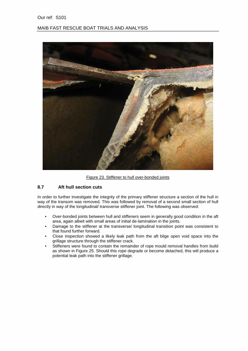
Figure 23. Stiffener to hull over-bonded joints 8.7 Aft hull section cuts In order to further investigate the integrity of the primary stiffener structure a section of the hull in way of the transom was removed. This was followed by removal of a second small section of hull directly in way of the longitudinal/ transverse stiffener joint. The following was observed:
• Over-bonded joints between hull and stiffeners seem in generally good condition in the aft area, again albeit with small areas of initial de-lamination in the joints.
• Damage to the stiffener at the transverse/ longitudinal transition point was consistent to that found further forward.
• Close inspection showed a likely leak path from the aft bilge open void space into the grillage structure through the stiffener crack.
• Stiffeners were found to contain the remainder of rope mould removal handles from build as shown in Figure 25. Should this rope degrade or become detached, this will produce a potential leak path into the stiffener grillage.

Our ref: S101 MAIB FAST RESCUE BOAT TRIALS AND ANALYSIS
Figure 24. Aft hull section cut
Crack in transition
between longitudinal
and transverse
girders
Rope mould
removal handles
Figure 25. Aft hull stiffener inspection cut

Our ref: S101 MAIB FAST RESCUE BOAT TRIALS AND ANALYSIS
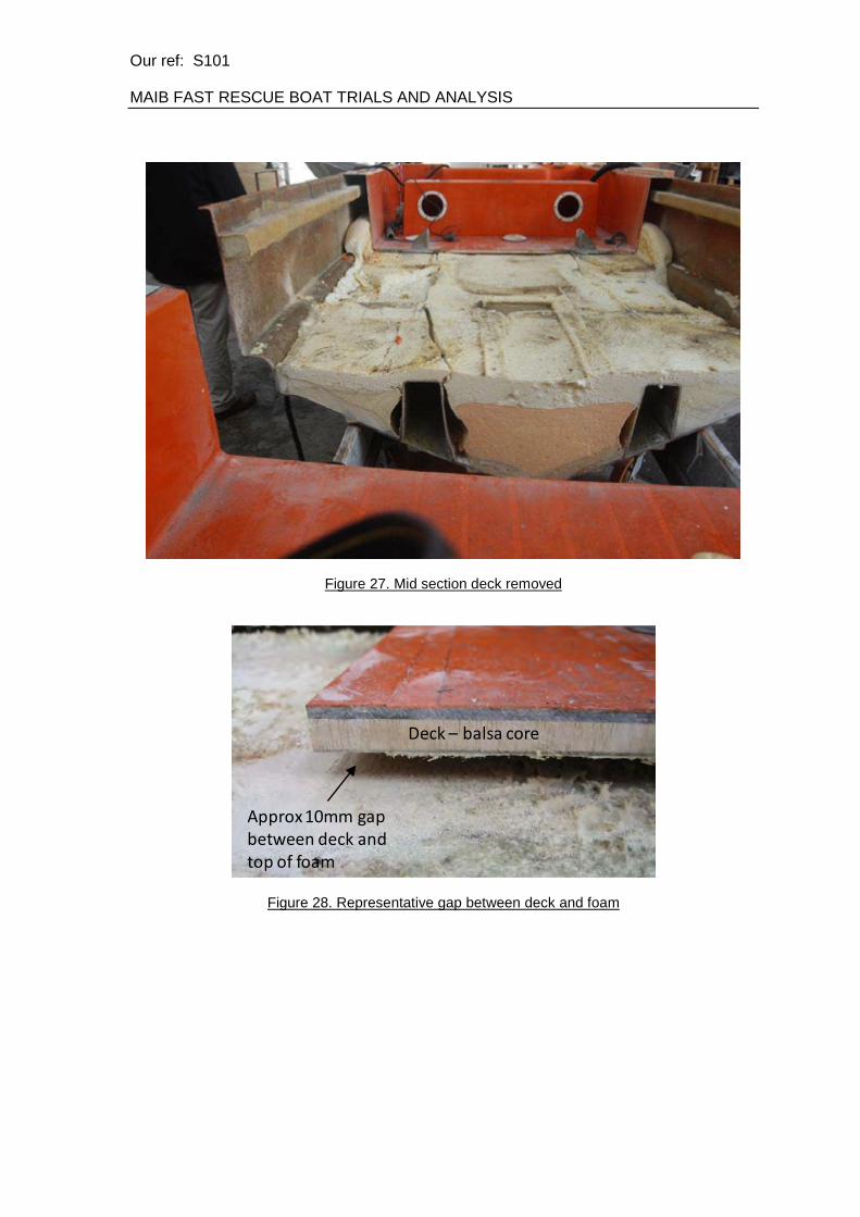
Figure 26. Representative damage to stiffener structure in aft transverse stiffener 8.8 Mid section examination An examination was carried out into the mid-section of the craft. In order to do this, the deck was removed in that area, and foam removed to show primary structure. It was decided that a full transverse cut was not required. The following was observed:
• Foam condition was consistent with that found at the front of the boat • Foam was wet for the outer 5-10mm, and then dry • A level of granularity was found in the outer 15-25mm of the foam, again at the boundary
with the hull. • Voids against sides of foam filled spaces were again present and consistent in size with
that found at the front • Second stage foam was in good condition. A longitudinal crack in the 2nd stage foam was
found, although it was inconclusive as to whether this was associated with the possible side impact damage. See Figure 27.
• A clear gap was again shown between the deck and the top of the 2nd stage foam as shown in Figure 28.
• Over-bonded joints between hull and stiffeners again seem in generally good condition in the mid area as shown in Figure 29.
• Starboard side stiffener damage was consistent to that found both forward and aft. • A small amount of additional stiffener damage (of a form consistent with that on the
Starboard side) was also found on the Port side. • The worst stiffener damage was investigated, with all foam removed. The crack was
found to span the stiffener crown, both across the transverse stiffener and the longitudinal stiffener as shown in Figure 30. The crack did not propagate down the stiffener webs.
Our ref: S101 MAIB FAST RESCUE BOAT TRIALS AND ANALYSIS
Figure 27. Mid section deck removed
Approx 10mm gap
between deck and
top of foam
Deck – balsa core
Figure 28. Representative gap between deck and foam

Our ref: S101 MAIB FAST RESCUE BOAT TRIALS AND ANALYSIS
Figure 29. Mid section primary structure
Figure 30. Mid section showing crack in way of the transverse and the longitudinal stiffener

Our ref: S101 MAIB FAST RESCUE BOAT TRIALS AND ANALYSIS
8.9 Side damage investigation An investigation was carried out into the apparent side damage experienced by this particular craft, with the following observations:
• The side shell stiffener was damaged in multiple places indicating a series of side impacts. This is likely to be consistent with launch and recovery operations.
• The side shell itself has been damaged and repaired. External gel coat crazing could be seen on close inspection.
• The stiffener cracking was mostly on the same side as the impact damage. This damage may or may not be linked.
Figure 31. Damage to side stiffener – example failure

Our ref: S101 MAIB FAST RESCUE BOAT TRIALS AND ANALYSIS
Figure 32. Hull Gel Coat crazing
Figure 33. Side shell damage repair

Our ref: S101 MAIB FAST RESCUE BOAT TRIALS AND ANALYSIS
8.10 Lift point investigation An investigation was made into the lift points, with the following observations:
• Three lift points were removed in their entirety. • Lifting fabrications appeared to be in good order. • Lifting fabrications were not bedded in effectively. • Lifting points did not line up with primary vessel structure. Position of aft lift point bolt was
very close to the transverse web, potentially nipping the web and causing a leakage path. • Lifting points passed through aluminium plates in the deck sandwich, although these were
unlikely to fulfil an effective structural purpose. • A visual survey was carried out of the above deck lifting frame and supplied lift ring. The
frame showed no signs of deformation, however the lift ring was deformed, indicating repeated lifting in an overweight condition.
9. TOMBARRA RESCUE BOAT 9.1 Preliminary Tombarra RB survey A preliminary survey was carried out (19-10-11) of the Tombarra RB, with the following observations:
• The Tombarra RB was in all critical respects a sister craft of the Trial FRB • Investigation into the structure carried out to date was extremely limited, and had not
included an assessment of the primary structure. • Investigation into the foam has been restricted to three areas only. • Figures for vessel weight post-accident were not available.
9.2 Secondary Tombarra RB survey A secondary survey was carried out on the Tombarra boat following the SOLAS and deconstruction work on the Trials boat. The following activities were carried out:
• Two holes (P+S) drilled in the transom for longitudinal girder inspection • Flexible borescope used to assess longitudinal and transverse stiffeners for cracking.
Inspect stiffeners from above using holes in deck as required • Non-invasive check for gel crazing externally to indicate any lateral impact damage • Check side shell girder for any evidence of lateral damage. • Measure locations of holes drilled already by the manufacturer in the presence of the
MAIB and determine positions relative to internal structure. • General assessment of vessel
The following was observed:
• No conclusive damage was found to the primary stiffeners, although only small areas could be inspected. The aft transverse was inspected Port and Starboard, as well as two additional locations on the transverse stiffeners just forward and just aft of the lift frame, one to Port and one to Starboard.
• 2nd stage injected foam had penetrated the aft section of the longitudinal stiffeners. This prevented further inspection forward (using the transom holes) but also indicated a leak path into the grillage.
• No evidence of lateral impact damage was found. • Drainage holes drilled by the manufacturer following the accident had almost exclusively
been located into the stiffener grillage. Those that were not were blind into foam and in some cases appeared to have been re-drilled to ensure access to the open grillage. Any

Our ref: S101 MAIB FAST RESCUE BOAT TRIALS AND ANALYSIS
water recorded by the manufacturer as drained from the vessel is therefore likely to have been trapped in the stiffener grillage space.
• Given that the FRB tested was FRB No.5 and Tombarra’s Rescue Boat was FRB No.124, the overall design of the vessel had improved. This could be seen in detailed areas such as the cable routing, which on the later boat is under the deck in a conduit with ‘witches hat’ seals at either end. Similarly trouser drains were more substantial and a recess Port and Starboard was provided for water to collect on deck.
10. STRUCTURAL ASSESSMENT RESULTS Having carried out the deconstruction work, the information gained was consolidated to address key areas of concern with the vessel. The structural damage described in this report is summarised in Figure 34. This figure shows observed damage only.
Side stiffener damage
Foam voids
(throughout boat)
Gel coat crazing
Transverse girder
cracking (stbd side)
Transverse and
longitudinal
cracking (stbd shown,
but port side also found)
Figure 34. Summary of damage locations

Our ref: S101 MAIB FAST RESCUE BOAT TRIALS AND ANALYSIS
10.1 Structural integrity The structural integrity of the hull shell and deck appeared good externally and was on the whole without signs of degradation, although there were areas with signs of gel coat cracking. Deck plugs were intact and were in good condition. The hull to deck joint was effective although presented a potential leakage path. The side shell showed significant damage on the Starboard side, with a fracture in every transverse stiffener crown where it meets the longitudinal stiffener. This was likely to compromise the vessels ability to attenuate side impacts during launch and recovery and was likely to have been caused by side impact during these operations. However it was also likely that the damage may be exacerbated by lifting operations with the boat in an overweight condition. There was also cracking damage on both the Port and Starboard side longitudinal stiffeners (in way of the aft lift points) that indicated a failure of longitudinal structure due to sagging on lifting. This hypothesis was potentially reinforced through the evidence of the bowed longitudinal stiffener web. A compound failure may be occurring whereby if the stiffener structure was not strong enough to survive through life, it may crack and flood, in turn adding weight to the boat and putting further strain on the stiffeners when lifting. 10.2 Buoyancy foam The buoyancy foam was on the whole in good condition, with only a small amount of water retention in the 5-10mm boundary layer. This was particularly the case not only in way of the hull shell, but also extending somewhat up the stiffener sides. The outer 25mm of the foam in the centre sections of the craft showed some signs of granularity in places, probably due to poor mixing and process control, or due to the cure state of the hull laminate, but this was not endemic. The remainder of the foam was dry and sound. Due to the manufacturing process, voids had been formed at the edges of each space into which the 1st stage foam was poured. Voids were likely to have been produced as the foam cured and contracted away from the sides, possibly contributed to by details in manufacturing process such as mix ratios. A rough estimate showed that edge voids may have constituted up to approximately 150kg of volume, representing approximately 10% of calculated buoyant volume. However, drain tests did not bear out such a strong presence of water in these spaces. Injected 2nd stage foam did not show the same level of void spaces. 10.3 Water ingress and weight growth It was accepted that water was retained in the various void spaces in the hull. It was similarly accepted that a number of leak paths were present, with some more obvious than others. Leak paths will vary from boat to boat. Despite local variations, it was proposed that the following was the most common scenario:
• Vessel fills with water when stored on ship due to defective or closed trouser drains. • Water leaks through deck gradually over time, through deck fixings or failed deck plugs • Water leaks through the aft void deck hatch. Depending on how well this hatch is fitted, it
may cause a greater accumulation of water if sealed better, as this allows water leaking from other locations to accumulate in the open side volumes at the aft end of the boat..
• Water runs under deck in gap over top of 2nd stage foam into large intentional void space at aft end of boat, filling boat to over top of second stage foam.
• Water was not drained from aft compartment and gradually works into open stiffener grillage, either through cracks or joints.
• Water works its way down from above into foam edge voids • Stiffener flooding and foam edge voids are not drained due to lack of limbering
arrangement.

Our ref: S101 MAIB FAST RESCUE BOAT TRIALS AND ANALYSIS
11. CONCLUSIONS The aims of the FRB trials work were to determine the effect of additional boat weight on compliance with SOLAS Type Approval requirements, and to analyse the structural integrity of the craft. The impact of trials findings on the craft’s ability to carry out its role as a Fast Rescue Craft was assessed. Although commonality of results with other craft in the fleet could not be directly appraised, potentially generic issues were investigated alongside specific findings. On the water the vessel was subjected to standard SOLAS Type Approval tests and was then cut apart in a logical manner to assess the structural integrity. Key issues in this investigation were:
• Water ingress and retention • The impact of weight growth on other vessel aspects such as operation and lifting • Structural fitness for purpose and design criteria
Having carried out the range of tests, it was possible to comment on the ability of the vessel to carry out it FRB role. The vessel was removed as tested from its ship and as such the MAIB tests have been representative of a trial of an overweight in-service craft. It was considered that the craft when in an overweight condition was not suitable for safe use as an FRB for the following reasons:
• Primary vessel structure was fundamentally damaged, potentially compromising the vessel’s ability to accept lifting loads. Lifting factors of safety are further reduced through the vessel being overweight. Failure of the lifting arrangement will have catastrophic consequences. Due to the nature of the design such a failure would be hidden from any maintenance activity.
• The deck has been shown to leak gradually and the design allows significant amounts of water to accumulate in the aft void (and open spaces at the aft end and gunwales of the boat), accounting for approximately 300kg of water in the case of this craft.
• Water retained by the craft in the open stiffener structure and foam edge voids cannot be drained. This can account for up to a further 500kg of water.
• The vessel would flood through the standard control cable transom conduit route, potentially causing stability problems and inadequate vessel freeboard in operation.
• If swamped, the vessel would not self-drain adequately. Due to reduced freeboard, swamping would be increasingly likely.
• The engine was very low in the water, which would potentially compromise its reliability, in particular in higher sea states.
• Vessel speed was heavily reduced, cutting down response times and therefore not fulfilling its role as a Fast Rescue Boat.
The above Fast Rescue Boat conclusions could similarly be applied to the vessel’s suitability for use as a standard Rescue Boat. Although the lower Rescue Boat speed criteria were met, the other issues relating to an overweight craft were still relevant, in particular the structural aspects and self-draining characteristics. It was proposed that the craft when in an overweight condition was not suitable for safe use as a Rescue Boat. 12. RECOMMENDATIONS SOLAS does not explicitly require structural calculations or Classification Society Plan Approval for the primary vessel structure, merely a first of class swing and drop proving test. It is recommended that this approach be discussed, and possibly added to through the application of side impact load design criteria and structural plan approval as part of the Type Approval process. The nature of the construction of the WHFRB 6.5 vessel means that it is impossible to ascertain whether the structure has been damaged during any first of class tests. Therefore unless the first of class is fully deconstructed following its Type Approval tests no damage would be visible. As

Our ref: S101 MAIB FAST RESCUE BOAT TRIALS AND ANALYSIS
such it is difficult to ascertain structural fitness for purpose using this test method. Similarly any routine maintenance would not identify any internal damage. Only external damage would be identified and repaired without understanding what latent damage may be elsewhere in the vessel. The consequences of stiffener damage may include the water retention shown on the trial boat but more importantly may also affect the boats structural ability to accept lifting frame loads. The consequences of this, in particular in a potentially already overweight boat, are severe. Due to the likely presence of voids in foam filled spaces it is suggested that some permeability factor is applied to designer’s buoyant volume calculations used in the Type Approval process. Permeability can be defined as the percentage of a foam filled space that is open space (as opposed to filled with foam). It is however proposed that permeability figures require more tests in isolation before representative figures are possible. It is considered that any further work on the foam be focussed on the effects of its use in a boat building context. With regard to improving the safety of new or existing craft it is proposed that the issues highlighted in this report can only be avoided by carrying out a specific formal safety assessment of any design that recognises that the following will inevitably occur:
• Water will be on the deck for long periods of time • Water will leak through the deck • Buoyant foam cannot be guaranteed to fill the hull void or remain so throughout the life of
the boat. In doing so the associated water retention hazards for any particular design could be assessed. It is proposed that locally on existing WHFRB6.5 craft the following are addressed as part of any formal safety assessment:
• Assess fleet urgently for extent of primary stiffener damage • Assessment of longitudinal and transverse strength to attenuate in-service loads, both
intact and following damage • Weight management and monitoring through life to be ensured • Block up controls conduit • Stiffener grillage drainage provision • Regular borescope inspection of the stiffener grillage through life • Regular inspection and repair of deck plugs and deck fixings • Inform operators in detail of the potential safety hazards (causes and effects) associated
with over-weight craft It is similarly proposed that on FRB new build areas such as the following could be addressed as part of any design formal safety assessment:
• Structural design criteria developed for side impact loads • Vessel designed to allow for through life inspection of void spaces • In-built drainage provision in all spaces • Foam materials and installation methods to avoid void spaces • Testing of foam installation to avoid spaces • Hand over and training documentation to include weight growth related issues

Annex C
Torrens rescue boat inspection report dated 29/3/2011


Norsafe Watercraft Hellas S.A.
7th Kilometre of the Old National RoadThebes to Chalkis
32200, Thebes, GREECE
Tel.: +30 2262 022 441 /Fax.: +30 2262 029 075
www.norsafe.com
INSPECTION REPORT
Vessel: M/V Torrens
Yard: N/A
Supplier/Subcontractor: USH
Product/Service: Rescue boat inspection
Owner: Wilhelmsen Lines
Date: 29/03/2011
Location: Piraeus , Greece
Norsafe WCH rep: ,
Boat Type: WHFRB 6.50 OUTBORD, RUBBER VERSION
Serial Number: 110
Build date: 02/07/2004
Hook type: N/A (LIFTING FRAME)
Introduction:
After vessel’s manager, , Wilhelmsen Lines and MAIB investigator request, we
inspected and checked the weight of the rescue boat.
Inspection:
The boat was weighted with full equipment and its weight and was found to be 1495kg. Moreover the engine found
on the rescue was not the one originally type approved engine supplied by the manufacturer and the weight of the
engine was about 40kg more then the weight of the original engine. Then we drilled holes underneath the hull to
access all compartments. From 15 compartments drilled, water was found in 5 of them. Most water was found in the
middle - aft sections. All other compartments were wet but no water was found inside. The water seemed to be salty
sea water.
Several areas of possible water ingress were found.
- The cables hole under the console was found completely unsealed. Water can easily penetrate from there.
- The inspection hatches of the crew seating bench were destroyed
- Many areas around the hull and deck were found repaired in a bad manner
- The screws around the helmsman’s console could also allow water to penetrate under the deck.
- Foaming application holes on the deck floor were found to be needing repair. Water can penetrate through
these holes if remains for a long time on the deck.
- Water can also penetrate from the lifting frame both from the deck and from the hull if not sealed with
sikaflex.
Conclusion:
MAIB and the vessel owners are concerned that the weight of the boat is higher than it should be when initially
supplied. The boat weight before dispatch from the factory was 1020Kgs with full equipment and without fuel. That
means the boat at the present time is approximately 500Kgs overweight. No Norsafe Watercraft personnel have
performed any annual inspections or any other kind of service onboard since the boat was delivered to Umoe Schat
Harding. The reason of the extra weight seems to be the sea water trapped inside the foam compartments.
Pictures follow.
Date: 11-07-2009 Norsafe Watercraft Hellas sign:

Norsafe Watercraft Hellas S.A.
7th Kilometre of the Old National RoadThebes to Chalkis
32200, Thebes, GREECE
Tel.: +30 2262 022 441 /Fax.: +30 2262 029 075
www.norsafe.com
Pictures taken during inspection
Weight of rescue boat before drain
General condition of rescue boat
Many places around the boat appeared
to have damages. Some have been
repaired.

Norsafe Watercraft Hellas S.A.
7th Kilometre of the Old National RoadThebes to Chalkis
32200, Thebes, GREECE
Tel.: +30 2262 022 441 /Fax.: +30 2262 029 075
www.norsafe.com
In many areas the gelcoat was missing
Osmosis can appear in these areas and
water can penetrate.
A big damage was found on aft port
side

Norsafe Watercraft Hellas S.A.
7th Kilometre of the Old National RoadThebes to Chalkis
32200, Thebes, GREECE
Tel.: +30 2262 022 441 /Fax.: +30 2262 029 075
www.norsafe.com
Protection rubber for cables found
damaged. Water can penetrate from this
area.
Inspection hatches are broken. Water
can penetrate in this compartment.
Open hole under the console foam is
exposed to water.

Norsafe Watercraft Hellas S.A.
7th Kilometre of the Old National RoadThebes to Chalkis
32200, Thebes, GREECE
Tel.: +30 2262 022 441 /Fax.: +30 2262 029 075
www.norsafe.com
Water drained form the middle
compartment
New engine on rescue boat
Hole not sealed under the console.
Water can penetrate from this area. The
hole was probably not sealed after the
new engine was fitted.

Norsafe Watercraft Hellas S.A.
7th Kilometre of the Old National RoadThebes to Chalkis
32200, Thebes, GREECE
Tel.: +30 2262 022 441 /Fax.: +30 2262 029 075
www.norsafe.com
Rescue boat weighted after the water
was drained

Annex D
Topeka rescue boat inspection report dated 28/3/2011


Page 1 of 5
Norsafe Watercraft Hellas S.A.
7th Kilometre of the Old National RoadThebes to Chalkis
32200, Thebes, GREECE
Tel.: +30 2262 022 441 /Fax.: +30 2262 029 075
www.norsafe.com
INSPECTION REPORT
Vessel: M/V TOPEKA
Yard: N/A
Supplier/Subcontractor: USH
Product/Service: Rescue boat inspection
Owner: Wilhelmsen Lines
Date: 28th of March 2011
Location: Baltimore, Washington, USA
Norsafe WCH rep:
Other persons attending: Vessel representative and
crew
Boat Type: WHFRB 6.50 outboard rubber fender version
Hook type: N/A lifting frame only
Introduction:
After vessel’s manager of Wilhelmsen Lines and MAIB investigator request, we inspected and
checked the weight of the rescue boat.
Inspection:
The boat was weighted with full equipment and fuel and after the drain the weight was found to be 1560kg. Holes
were drilled underneath the hull to access all compartments. From 15 compartments drilled, water was drained from
most of them. Most water was found in the aft compartments. The water seemed to be salty sea water. Drilled holes
were then closed with bolts and sikaflex.
Several areas of possible water ingress were found.
- One hole of 8mm was found under the hull for unknown reason. Water can penetrate from this hole.
- 10 different open holes were found on various places on the deck. Water can penetrate through these holes
if remains for a long time on the deck. The foam inside them was wet.
- The screws around the helmsman’s console were not watertight and could also allow water to penetrate
under the deck.
- Water can also penetrate from the lifting frame both from the deck and from the hull. Silicone was applied.
Conclusion:
No Norsafe Watercraft personnel have performed any annual inspections or any other kind of service onboard since
the boat was delivered to Umoe Schat Harding. The reason of the extra weight seems to be the sea water trapped
inside the foam compartments.
Pictures follow.

Page 2 of 5
Norsafe Watercraft Hellas S.A.
7th Kilometre of the Old National RoadThebes to Chalkis
32200, Thebes, GREECE
Tel.: +30 2262 022 441 /Fax.: +30 2262 029 075
www.norsafe.com
An 8mm hole was found during
inspection under the hull for unknown
reason.
General condition of the boat

Page 3 of 5
Norsafe Watercraft Hellas S.A.
7th Kilometre of the Old National RoadThebes to Chalkis
32200, Thebes, GREECE
Tel.: +30 2262 022 441 /Fax.: +30 2262 029 075
www.norsafe.com
Water pouring out of the holes drilled
Water pouring out of the holes below
the hull starboard side.
Water pouring out of the holes

Page 4 of 5
Norsafe Watercraft Hellas S.A.
7th Kilometre of the Old National RoadThebes to Chalkis
32200, Thebes, GREECE
Tel.: +30 2262 022 441 /Fax.: +30 2262 029 075
www.norsafe.com
Foam filling holes on deck floor found
open and destroyed.
Foam filling holes on deck floor found
open
Foam filling holes on deck floor found
open and destroyed.

Page 5 of 5
Norsafe Watercraft Hellas S.A.
7th Kilometre of the Old National RoadThebes to Chalkis
32200, Thebes, GREECE
Tel.: +30 2262 022 441 /Fax.: +30 2262 029 075
www.norsafe.com
After the drain, the boat was weighted
and found 1660-100(engineer’s weight)
=1560kg
Water was leaking from the lifting frame
I sealed the lifting frame with sikaflex


Annex E
Topeka rescue boat inspection report 2 dated 15/7/2011


Page 1 of 6
Norsafe Watercraft Hellas S.A.
7th Kilometre of the Old National RoadThebes to Chalkis
32200, Thebes, GREECE
Tel.: +30 2262 022 441 /Fax.: +30 2262 029 075
www.norsafe.com
INSPECTION REPORT 2
Vessel: M/V TOPEKA
Yard: N/A
Supplier/Subcontractor: USH
Product/Service: Rescue boat inspection
Owner: Wilhelmsen Lines
Date: 15th of July 2011
Location: Norsafe Watercraft Hellas, Thebes, Greece
Persons attending:
, Production manager
, Quality Controller
, GRP foreman
, General Manager
Boat Type: WHFRB 6.50 outboard rubber fender version s/n 128
Hook type: N/A lifting frame only
Introduction:
Following up the findings on the rescue boat on board M/V Topeka as stated on inspection report dated 28/3/2011,
the boat was send to the factory in order to evaluate possibility of repair. Practical tests were also performed in order
to verify the reasons of water penetration to the foam compartments.
Inspection:
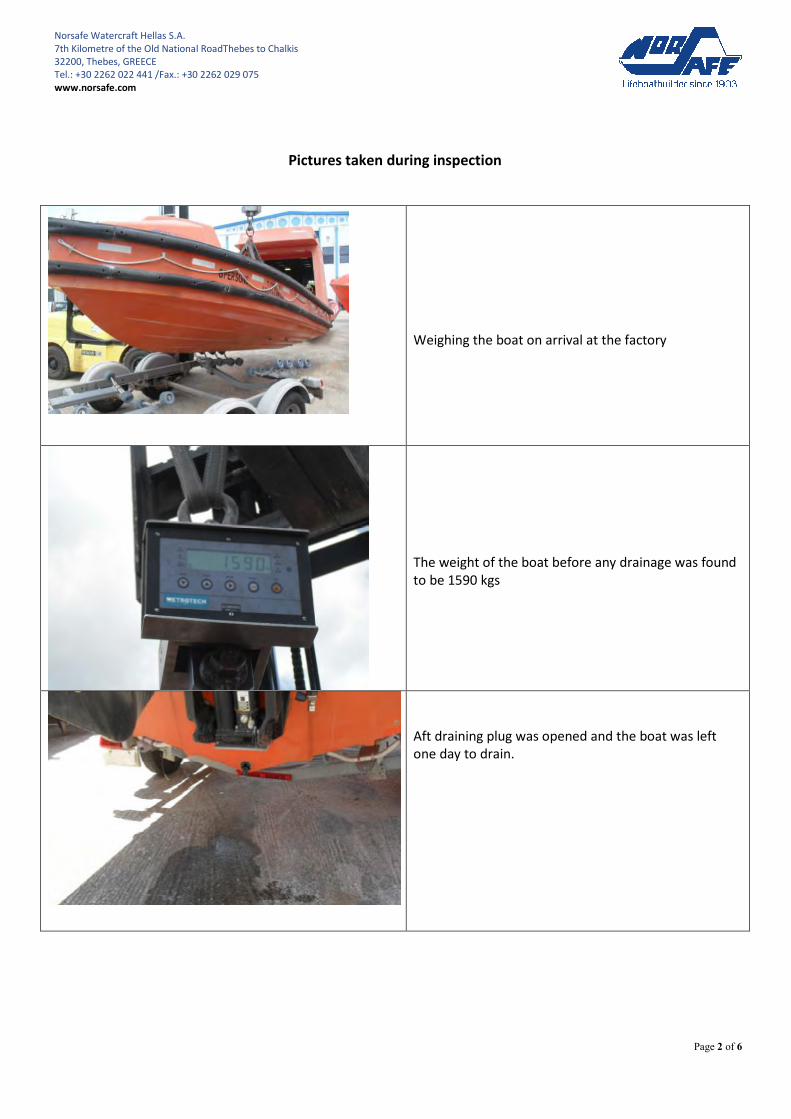
The boat when came to the factory was weighted with full equipment and fuel and found to be 1590 Kgs. The aft
draining valve was opened and some water came out. The boat was weighted again after draining and found to be
1530 Kgs. All openings sealed with sikaflex by Norsafe Watercraft service engineer during his visit on board the vessel
on the 28th
of March were inspected and found in good condition.
The boat deck was then filled with water up to a level of 25 mm. Air was blown from the aft draining valve in order to
check possible openings. No air bubbles appeared anywhere on the deck or hull. Some air was coming out from a
damaged area in the GRP in the fore part of the boat.
We opened the areas where our service engineer had sealed during inspection. Air was coming out from these
openings.
Then the deck was cut and removed from the boat. Water was found in almost all foam compartments. The foam
was destroyed and water had penetrated to every opening. Foam and water were removed from the boat. All
equipment and GRP deck was put back in place and the boat was weighted again. The weight of the boat with full
extra equipment and fuel, without the foam and water was 1078 Kgs.
Conclusion:
The reason of the extra weight was water trapped inside the foam compartments. Water has penetrated in these
compartments from damaged and unsealed areas on the deck and the hull.
Repair to its original condition is possible.
Pictures follow.
Page 2 of 6
Norsafe Watercraft Hellas S.A.
7th Kilometre of the Old National RoadThebes to Chalkis
32200, Thebes, GREECE
Tel.: +30 2262 022 441 /Fax.: +30 2262 029 075
www.norsafe.com
Pictures taken during inspection
Weighing the boat on arrival at the factory
The weight of the boat before any drainage was found
to be 1590 kgs
Aft draining plug was opened and the boat was left
one day to drain.

Page 3 of 6
Norsafe Watercraft Hellas S.A.
7th Kilometre of the Old National RoadThebes to Chalkis
32200, Thebes, GREECE
Tel.: +30 2262 022 441 /Fax.: +30 2262 029 075
www.norsafe.com
The boat weight after draining was 1530 Kgs
The deck was filled with water and air was inserted
from the aft draining plug. No air leakage was
observed.
Same comment as above.

Page 4 of 6
Norsafe Watercraft Hellas S.A.
7th Kilometre of the Old National RoadThebes to Chalkis
32200, Thebes, GREECE
Tel.: +30 2262 022 441 /Fax.: +30 2262 029 075
www.norsafe.com
When the sealed holes or damages where opened, air
was flowing with pressure.
Same comment as above.
Same comment as above.

Page 5 of 6
Norsafe Watercraft Hellas S.A.
7th Kilometre of the Old National RoadThebes to Chalkis
32200, Thebes, GREECE
Tel.: +30 2262 022 441 /Fax.: +30 2262 029 075
www.norsafe.com
Same comment as above.
A lot of air was getting out of this damaged area
between the hull and deck.
The deck was cut and removed from the boat.

Page 6 of 6
Norsafe Watercraft Hellas S.A.
7th Kilometre of the Old National RoadThebes to Chalkis
32200, Thebes, GREECE
Tel.: +30 2262 022 441 /Fax.: +30 2262 029 075
www.norsafe.com
The foam compartments were filled with water. White
areas: foam is dry, Yellow areas: foam is wet but there
is no water, dark areas: foam is filled with water.
The foam and water was removed and the boat was
weighted. The weight was found to be 1078.
End of report

Annex F
Tecfoam technical data sheet


tecfoam
2-component polyurethane systems
Notice: All Statements, information and data given herein are believed to be accurate and reliable but are presented without guarantee, warranty or responsibility of any kind expressed or implied. Statements or suggestions concerning possible use of the products are made without representation or warranty that any such use is free of patent infringement, and are not recommendations to infringe any patent. The user should not assume that all safety measures are indicated or that other measures may not be required.
TECTRADE A/S KRONBORGVEJ 24 DK-5450 OTTERUP TLF.: +45 63 93 93 93 FAX.: +45 63 93 93 99
WEB-SITE: www.tectrade.dk E-MAIL: [email protected]
TECHNICAL DATASHEET
Polyol-system:
TECFOAM CIVIOL 1642
Isocyanate to the system: DESMODUR 44 V 20 L Specific gravity at 22 [C]: 1,23-1,24 [g/ml]
Product characteristic: 2-component low density rigid polyurethane foam.
Application: Foaming of rescue boats where no preheating is possible.
Special properties: The system is 100% HCFC free, as water (CO2) and 134a are used as the only blowing agents. A mixture of sorbitol polyether polyols and triols gives an excel-lent cell structure, and secures good mechanical properties and good density distribution is achieved. The use of special surface active additives gives the best possible adhesion on all usual construction materials.
Typical properties: Specific gravity at 22 [C]: 1,07 +/- 0,01
Viscosity at 24 [C]: 700 +/- 50 Ratio: -in weight: ISO/POL = 120/100 Reaction profile: hand mix HP machine -cream time: 55 +/- 9 -fiber time: 260 +/- 20 -tack free time: 600 +/- 35 -free rise density: 41,0 +/- 2,0
[g/ml] [mPas] [cP] [g/g] [sec] [sec] [sec] [g/l]
Typical processing data: Temperature on polyol and isocyanate: 18-22 Recommended moulding temperature: 18-22
[C] [C]
Note: This system is approved according to Registro Italiano Navale (R.I.N.A.) and The Norwegian Veritas (D.N.V.) for cavity filling of rescue boats.

tecfoam
Polyol-system: TECFOAM CIVIOL 1642
Notice: All Statements, information and data given herein are believed to be accurate and reliable but are presented without guarantee, warranty or responsibility of any kind expressed or implied. Statements or suggestions concerning possible use of the products are made without representa-tion or warranty that any such use is free of patent infringement, and are not recommendations to infringe any patent. The user should not assume that all safety measures are indicated or that other measures may not be required.
TECTRADE A/S KRONBORGVEJ 24 DK-5450 OTTERUP TLF.: +45 63 93 93 93 FAX.: +45 63 93 93 99
WEB-SITE: www.tectrade.dk E-MAIL: [email protected]
Delivery: Drum, IBC or truckloads.
Use before: 6 months.
Handling and storage: Polyol can absorb moisture from the air. Keep the container tightly closed in a cool, well-ventilated place. Store between 15 and 30°C and keep away from food and other feeding stuff. The material is not included by the regulation of storing of flammable liquids.
Regulatory information: Classification: R52/53 R-phrases: R52/53: Harmful to aquatic organisms, may cause long-
term adverse effects in the aquatic environment. S-phrases: S35: This material and its container must be disposed of in a safe way.
Exposure controls/
personal protection: Handle with adequate ventilation. Mechanical ventilation, local ventilation or alike may be necessary. Normally rules about cleanliness working with chemicals has to be considered. Suitable respiratory equipment should be used in cases of insuffi-cient ventilation or where operational procedures demand it. Use suitable gloves (neoprene, nitrile butadiene rubber, butyl rubber, PVC) and working cloths if there is a risk for contact with skin. Thin disposable gloves should be avoided for re-peated or long term use. Use chemical safety glasses/goggles or full face shield if there is a risk of splashing. There has to be an easy way to get eyewash or running water.
Accidental release: Avoid contact with eyes and skin. In case of waste or leak trap the liquid with barricades. Waste is not allowed to enter drains. If there is a risk for pollution of lakes, streams and drains the authori-ties must be informed. Stop small leaks, if it can happen without risks. Liquids may be soaked up with sand or soil, shovelled up and kept in a closed container or tank. Rinse with plenty of water with liquid detergent.
Fire-fighting measures: Foam, CO2 dry powder or water spray. Do not use solid water stream – may spread
fire. Use water and water spray for cooling down storeroom, which is not on fire. Avoid inhalation of vapours and gases. Suitable respiratory protection with full face piece and positive air supply. PVC boots, gloves and protective clothing should be worn.
Date: 30.07.03/el & 16.08.2004/jaj

Annex G
Tecphen technical data sheet

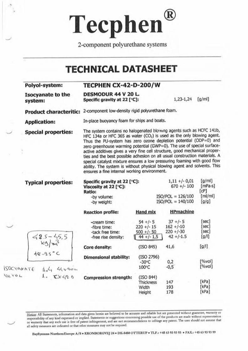


Annex H
MAIB Safety Bulletin 1/2011


MAIB SAFETY BULLETIN 1/2011
Overweight rescue boat identified during the investigation into the failure of a fall wire with the loss of one life
on the car carrier Tombarra
Marine Accident Investigation BranchMountbatten House
Grosvenor SquareSouthampton
SO15 2JU

MAIB SAFETY BULLETIN 1/2011
This document, containing safety lessons, has been produced for marine safety purposes only, on the basis of information available to date.
The Merchant Shipping (Accident Reporting and Investigation) Regulations 2005 provide for the Chief Inspector of Marine Accidents to make recommendations at any time during the course of an investigation if, in his opinion, it is necessary or desirable to do so.
Steve ClinchChief Inspector of Marine Accidents
NOTE
This bulletin is not written with litigation in mind and, pursuant to Regulation 13(9) of the Merchant Shipping (Accident Reporting and Investigation) Regulations 2005, shall not be admissible in any judicial proceedings whose purpose, or one of whose purposes, is to apportion liability or blame.
This bulletin is also available on our website: www.maib.gov.ukPress Enquiries: 020 7944 6433/3387; Out of hours: 020 7944 4292
Public Enquiries: 0300 330 3000

BACKGROUNDAt approximately 1550 (UTC) on 7 February 2011, the fall wire attached to the rescue boat of the UK registered car carrier Tombarra parted during a routine drill which was being conducted in the sheltered waters of the Royal Portbury Docks, Bristol, UK. The accident occurred at the point when the rescue boat had been hoisted to its stowed position. The rescue boat and its four crew fell nearly 29m into the water below. One of the boat’s crew died and two were hospitalised.
The rescue boat, a Watercraft WHFRB 6.50 had a certified weight of 980kg, but was 1450kg when weighed after the accident (Figure 1). Subsequently, several rescue boats of the same model carried on board Tombarra’s sister vessels were also inspected and weighed, and they too were found to be significantly heavier than when supplied.
In all cases, in an unladen state, the boats’ weights were close to or exceeded the safe working load (SWL) of their davits. With crew, fuel and equipment on board, the SWLs of the davits were exceeded.
However, the weight of Tombarra’s rescue boat by itself should not have resulted in the failure of its fall wire due to the safety margins in place. Investigation into the failure of the wire remains ongoing and it is anticipated that a further safety bulletin will be published shortly.
Weighing of the rescue boat
Figure 1

INITIAL FINDINGSThe rescue boat was manufactured by Watercraft Hellas SA and delivered to Tombarra in 2006. The Watercraft WHFRB 6.50 was certified to meet the requirements of SOLAS, the Life Saving Appliance (LSA) Code and the Marine Equipment Directive (MED).
The WHFRB 6.50 was constructed with an inner and outer hull. The void below deck was divided into 16 compartments, 15 of which were filled with rigid polyurethane foam to provide a watertight, buoyant volume.
Investigation has identified that 14 of the 15 foam-filled compartments in Tombarra’s rescue boat had been penetrated by water. In addition, the foam in the lower sections of the hull contained cavities and there were voids between the foam and the hull. In these areas the foam appeared to be of varying consistency and colour (Figures 2 & 3).
Below deck inspection
Figure 2
Foam sample from cavity
Figure 3
Free water Cavity

Although the boat was fitted with a drain plug on the transom, the internal compartments were not interconnected. The removal of the plug therefore allowed the water to drain only from the aftermost compartment. The water in the remaining compartments was trapped and had to be drained by separately drilling into each compartment through the hull (Figure 4).
Investigation into how water entered the buoyancy compartments of the boats inspected has identified a number of different types of penetrations in their hulls and decks. Investigation into the properties of the foam used is ongoing.
SAFETY ISSUESWater ingress and retention within the foam-filled internal compartments of the Watercraft WHFRB 6.50 is a serious cause for concern. It is apparent that, without warning, it can result in a boat’s weight increasing considerably over time, with the following consequences:• the SWL of the davit and fall could be exceeded
• the rescue boat’s performance and manoeuvrability could be adversely affected in relation to:• the ability to self-right (or be righted) after capsize• the ability to tow survival craft, and
• safety of the 5-yearly dynamic test where the boat is included in the test weight could be compromised.
Water draining from foam-filled compartments
Figure 4
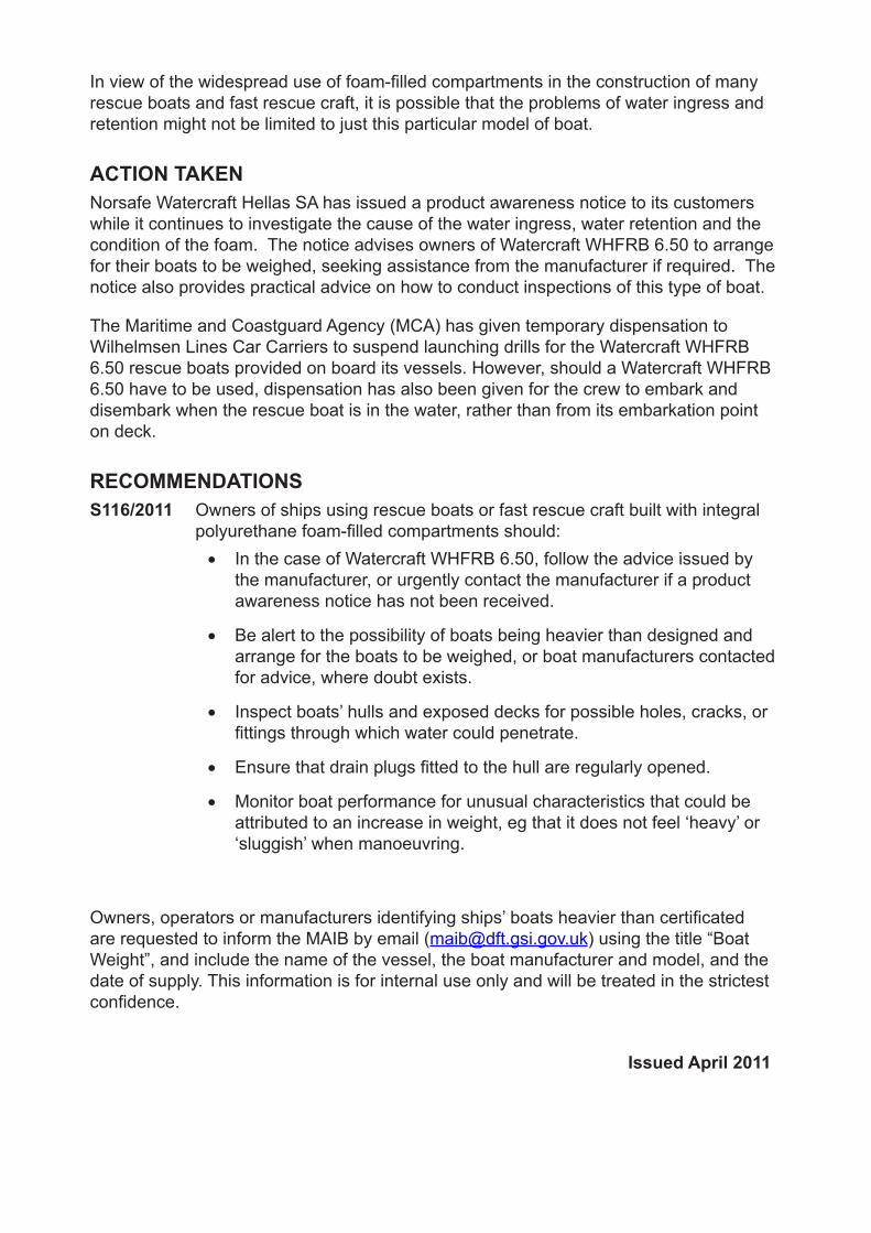
In view of the widespread use of foam-filled compartments in the construction of many rescue boats and fast rescue craft, it is possible that the problems of water ingress and retention might not be limited to just this particular model of boat.
ACTION TAKENNorsafe Watercraft Hellas SA has issued a product awareness notice to its customers while it continues to investigate the cause of the water ingress, water retention and the condition of the foam. The notice advises owners of Watercraft WHFRB 6.50 to arrange for their boats to be weighed, seeking assistance from the manufacturer if required. The notice also provides practical advice on how to conduct inspections of this type of boat.
The Maritime and Coastguard Agency (MCA) has given temporary dispensation to Wilhelmsen Lines Car Carriers to suspend launching drills for the Watercraft WHFRB 6.50 rescue boats provided on board its vessels. However, should a Watercraft WHFRB 6.50 have to be used, dispensation has also been given for the crew to embark and disembark when the rescue boat is in the water, rather than from its embarkation point on deck.
RECOMMENDATIONSS116/2011 Owners of ships using rescue boats or fast rescue craft built with integral polyurethane foam-filled compartments should:
• In the case of Watercraft WHFRB 6.50, follow the advice issued by the manufacturer, or urgently contact the manufacturer if a product awareness notice has not been received.
• Be alert to the possibility of boats being heavier than designed and arrange for the boats to be weighed, or boat manufacturers contacted for advice, where doubt exists.
• Inspect boats’ hulls and exposed decks for possible holes, cracks, or fittings through which water could penetrate.
• Ensure that drain plugs fitted to the hull are regularly opened.
• Monitor boat performance for unusual characteristics that could be attributed to an increase in weight, eg that it does not feel ‘heavy’ or ‘sluggish’ when manoeuvring.
Owners, operators or manufacturers identifying ships’ boats heavier than certificated are requested to inform the MAIB by email ([email protected]) using the title “Boat Weight”, and include the name of the vessel, the boat manufacturer and model, and the date of supply. This information is for internal use only and will be treated in the strictest confidence.
Issued April 2011

Annex I
Norsafe Watercraft Hellas - Product Awareness Notice


Page 1
PAN Subject: PAN-ident PAN2011-01
Distribute to customer:
Description of the background for this PAN:
Recommended activity:
Comments:
ALL CUSTOMERS, END USERS
Approved by SVP Techinical Dept:
Document referenceWATERCRAFT HELLAS WHFRB 6.50 FAST
RESCUE BOAT
This PAN
applies to type of
Life Saving Appliance :
PANPRODUCT AWARNESS NOTICE
OVERWEIGHT POSSIBILITY
We recommend that in the first convenient port you weigh the boat after you have made sure that the aft
compartment is drained by opening the aft drain plug. Check / inspect for cracks and holes in the deck and
on the outside hull.
If the weight is over 10% of the weight stated on the manufacturer's plate, please inform Watercraft Hellas
s.a. in order our specialized service engineers to advise you for further actions. Use of a calibrated scale is
neccessary.
Issue Date: 8/4/2011Authorised by Technical manager:
It has come to our knowledge that a Fast rescue boat model manufactured by Watercraft Hellas s.a., a
brand recently acquired by Norsafe Group, may under lack of proper maintenance become overweighted.
As a result of weighing this type of boat on at least two vessels it was found that the boats were overweight
by at least 40% of their original total weight including fuel and equipment. The reason of overweight was
water (both sea water and rain water) that had penetrated below the deck area and had been trapped in
the buoyancy foam compartments. Eventually the foam was destroyed after prolonged exposure to water
and temperature fluctuations. It should be noted that no draining possibility is provided for these
compartments as they are designed as closed compartments and should also be maintained as closed and
sealed compartments to prevent water penetration and keeping this area watertight is the only way to
prevent water penetration. Lack of maintenance, minor or major cracks on the GRP, unsealed openings or
holes both in the hull or deck of the boat can result in water penetration and consequently adding of weight
to the boat itself. This however does not mean that your boat is overweighted but that there can be a
potential risk for water ingress, in case there has not been any special attention to this by regular
maintenance and control.
For further information, please contact our company by telephone or e.mail
telephone: +30 2262022441 e.mail: [email protected]

Page 2
PAN Subject: PAN-ident PAN2011-01
Supplying information
OVERWEIGHT POSSIBILITY
PANPRODUCT AWARNESS NOTICE
This PAN
applies to type of
Life Saving Appliance :
WATERCRAFT HELLAS WHFRB 6.50 FAST
RESCUE BOAT
Document reference
Aft drain plug
For further information, please contact our company by telephone or e.mail
telephone: +30 2262022441 e.mail: [email protected]