tooth-form optimisations and modifications specifically for plastic
TRANSCRIPT

KISSsoft 03/2013 – Tutorial 11
Tooth Form Optimizations, Tooth Form Modifications specifically for Plastic, Sintered, Wire-eroded and Form-forged Gears
KISSsoft AG
Rosengartenstrasse 4
8608 Bubikon
Switzerland
Tel: +41 55 254 20 50
Fax: +41 55 254 20 51
www.KISSsoft.AG

05.03.2013 2 / 36
Contents
1 Introduction .............................................................................................................................................. 3 1.1 Summary of the design strategy ..................................................................................................... 3 1.2 Introduction ..................................................................................................................................... 3
2 Defining Tooth Geometry ......................................................................................................................... 4 2.1 Introduction ..................................................................................................................................... 4 2.2 Tip-rounding ................................................................................................................................... 4 2.3 Minimum tooth thickness at the tip ................................................................................................. 9 2.4 Geometry changes for a predefined reference profile .................................................................. 10 2.5 Changing geometry by varying the reference profile .................................................................... 11 2.6 Eliminating contact shock by correcting the tooth form ................................................................ 12 2.7 Optimizing the tooth root .............................................................................................................. 15 2.8 Checking the meshing .................................................................................................................. 16 2.9 Checking for seizure in the gears ................................................................................................. 18
3 Strength calculation................................................................................................................................ 19 3.1 Introduction ................................................................................................................................... 19 3.2 Input your own data for plastics .................................................................................................... 19 3.3 Strength calculation with consideration of effective tooth form ..................................................... 22
4 Defining the Tooth Thickness Deviation ................................................................................................ 25 4.1 Introduction ................................................................................................................................... 25 4.2 Calculating operating backlash ..................................................................................................... 25 4.3 Increasing operating backlash ...................................................................................................... 27
5 Calculating the injection mould .............................................................................................................. 28 5.1 Introduction ................................................................................................................................... 28 5.2 Modifying the injection mold to compensate for shrinkage ........................................................... 29 5.3 Display the eroding wire / spark gap ............................................................................................ 32 5.4 Monitoring the wire diameter during erosion ................................................................................ 35 5.5 Calculating a 3D mold .................................................................................................................. 36
05.03.2013 3 / 36
1 Introduction
1.1 Summary of the design strategy
These instructions describe a strategy for optimizing the design of gears that are manufactured using
molding methods (injection molding, sintering, forging etc.). These special methods for sizing and optimizing
gears manufactured using these methods are integrated in the KISSsoft calculation software.
The sizing process involves these steps:
Define the approximate sizes (module, face width, etc) using the strength calculation
Define allowances
Optimize tooth depth (aim: achieve effective transverse contact ratio 2.0 whilst taking into account
tip rounding, running-in curve for noise reduction)
Tip-rounding
Optimize running-in curve/profile modification (aim: noise reduction, improve wear safety)
Optimize root fillet (increase the root safety factor)
Determine a mould for the manufacturing process
1.2 Introduction
Nowadays, gears are increasingly manufactured from plastics because the development of new materials
has made them able to achieve increasingly higher load capacities. The special properties of plastics allow
them to be used in many more areas than steel. A designer can therefore select the best possible plastic
material for their particular application. Some of the most important properties to be taken into consideration
when designing a gear pair are therefore its load capacity, resistance to wear, damping characteristics,
stiffness and also noise development.
Metallic gears are usually manufactured in a hobbing process. In contrast, plastic gears are usually injection
molded. If the mold is produced by a wire erosion process, the tooth form can be optimized at no additional
cost. In a hobbing process, this is only possible with expensive, specialist tools. However, the injection
molding process does not achieve a particularly good accuracy grade and, once again, this is a problem
that can only be solved by implementing specific measures. Gears that have been modified in this way are
referred to as hybrid tooth forms in the technical literature.
The KISSsoft calculation software includes a large number of special methods for sizing and optimizing
plastic gears. These procedures are fully integrated into a comprehensive, modern software system that
enables you to develop and monitor both standard and hybrid toothing.

05.03.2013 4 / 36
2 Defining Tooth Geometry
2.1 Introduction
You can change tooth geometry in many different ways to achieve the optimum ratio of meshing.
Depending on the importance of the targets to be achieved, such as low noise emission, low vibration,
strength, slip, stiffness and balance, you must prioritize the measures to be taken.
When you start this optimization process, we recommend you set the following defaults:
2.2 Tip-rounding
For tooth forms produced using a molding process, the tooth tip edges must be rounded, because corners
can never be created accurately in injection molding. It is a good idea to input this data in the main screen
for gear 1 and gear 2. This ensures that all the most important data (such as contact ratio, etc.) can be
calculated whilst taking the tip rounding into account.
The is illustrated in the following example: KISSsoft provides an example file for this specific calculation.
Open this file in the helical gear calculation module:
Figure 1. Opening the helical gear calculation module and then the CylGearPair 1 (spur gear) example file
05.03.2013 5 / 36
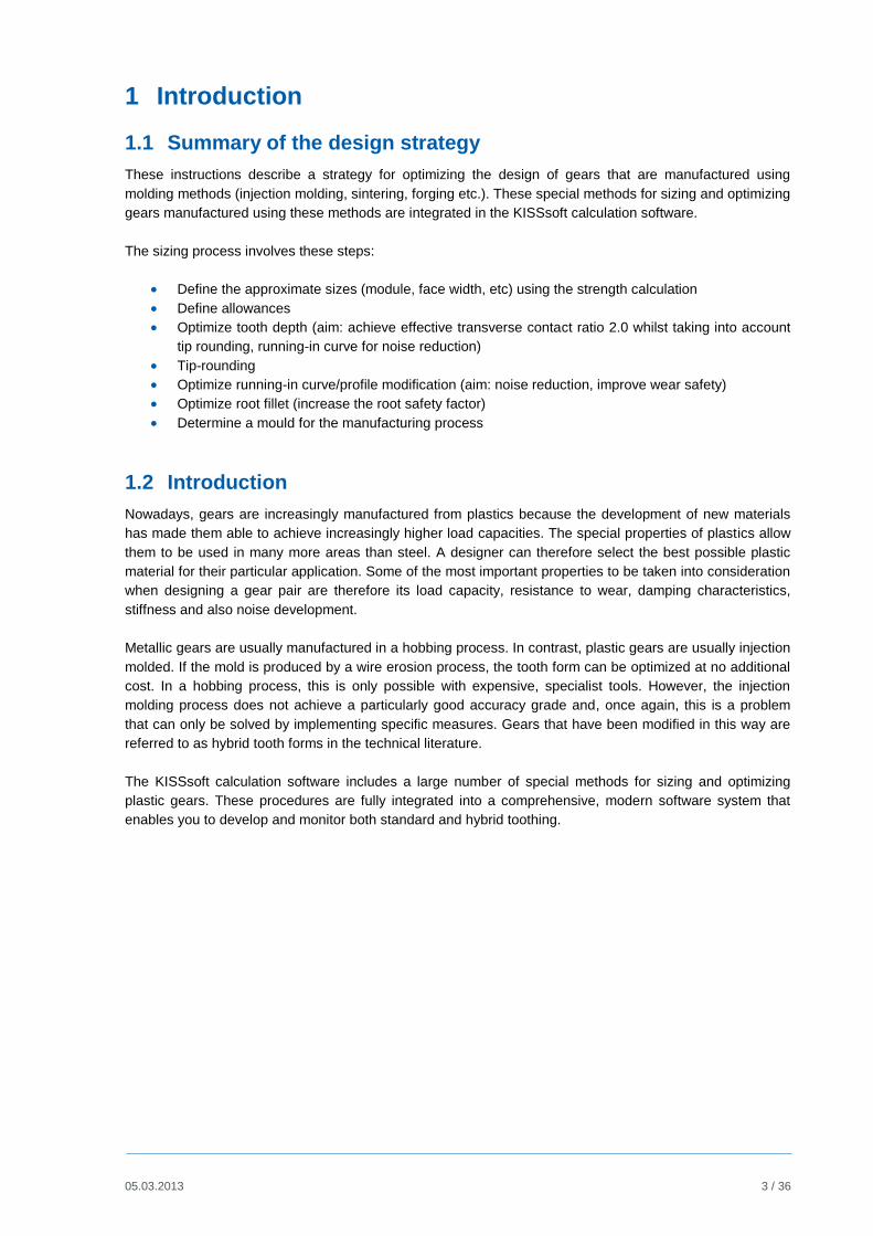
Figure 2. Example file for plastic gears, after running "Σ"
Either click on the icon in the Tool bar or press "F5" to calculate the toothing shown in this example.
Without tip-rounding the contact ratio would be 1.6686. You can see the tooth form as a graphic in the lower
part of the window. You can also view the tooth form here and move it to the required position (see the
marking on the lower right in Figure 2).
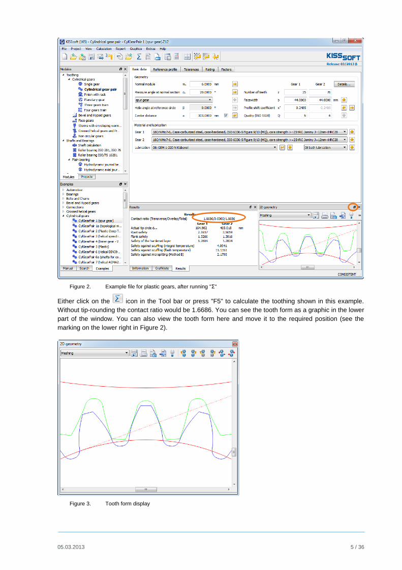
Figure 3. Tooth form display
05.03.2013 6 / 36
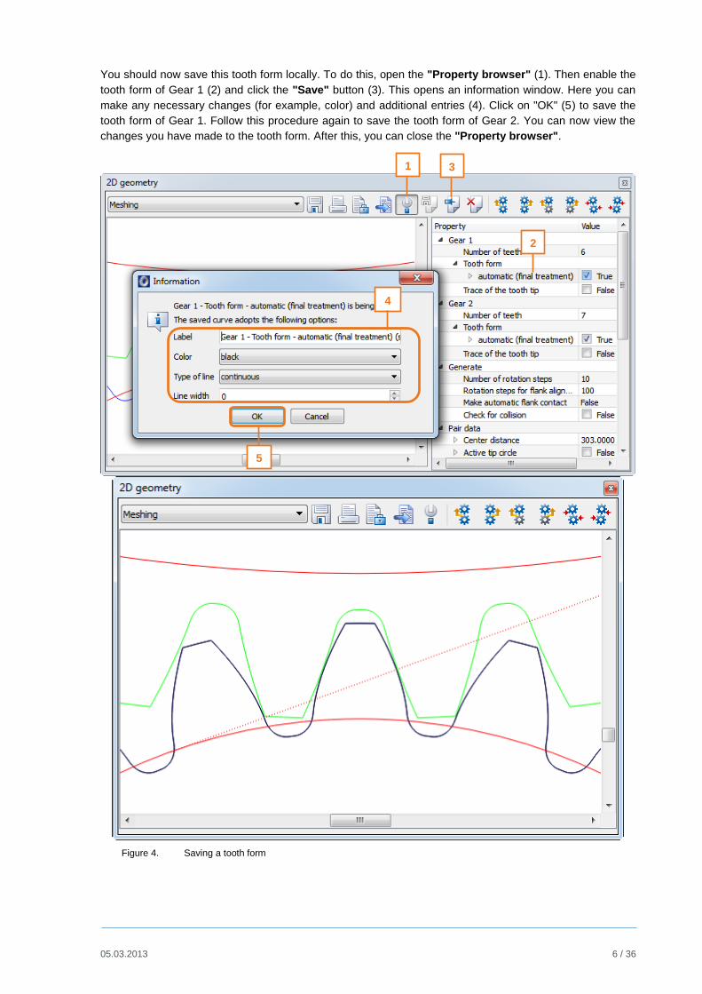
You should now save this tooth form locally. To do this, open the "Property browser" (1). Then enable the
tooth form of Gear 1 (2) and click the "Save" button (3). This opens an information window. Here you can
make any necessary changes (for example, color) and additional entries (4). Click on "OK" (5) to save the
tooth form of Gear 1. Follow this procedure again to save the tooth form of Gear 2. You can now view the
changes you have made to the tooth form. After this, you can close the "Property browser".
Figure 4. Saving a tooth form
1 3
2
4
5

05.03.2013 7 / 36
The tip rounding is defined as follows in the "Modifications" tab (add the tab via "Calculation"
"Modifications") for Gear 1 and Gear 2 (see figure 5):
Figure 5. Definition of tip rounding, in this case 2mm radius
Then click on to repeat the calculation and accept the rounding. If you look carefully at the graphic, you
will see the rounding on the teeth. The original tooth form is also displayed (in black/green or blue).
Figure 6. Rounded tooth tip
Important note:
When you save the tooth form, all previous calculation operations are also active.
In some cases, it may be better to monitor the changes you have made by activating and deactivating each
individual step of the calculation.

05.03.2013 8 / 36
You can also reset the graphic properties. This happens automatically when you change the display in the
geometry window. Alternatively, you can select "Extras" "Configuration tool" in the "Settings" tab and
click on "Graphics" "Reset".
Figure 7. Resetting "Graphic properties"
Figure 8. Activating all calculation operations

05.03.2013 9 / 36
In the main screen, the value calculated for the contact ratio has dropped to 1.3712:
Figure 9. Reduction of contact ratio as the result of tip rounding
2.3 Minimum tooth thickness at the tip
In the KISSsoft system, the default value for the necessary minimum tooth thickness is 0.2*module.
However, for plastic gears (with tip rounding) this value is rather low. You should set it to 0.4*module
instead. Do this in "Module specific settings" in the "General" tab:
Figure 10. Specifying the necessary minimum tooth thickness at the tip in the module specific settings

05.03.2013 10 / 36
Essential and effective measures for optimizing geometry are:
2.4 Geometry changes for a predefined reference profile
You can significantly alter the tooth geometry by varying the module, pressure angles, helix angle and
profile shift of a specific reference profile. In particular, for helically toothed cylindrical gears, you can
usually find an optimum solution with this approach. Here, the KISSsoft software programs provide a
especially effective tool for optimizing the design. The fine sizing functions generate all the possible
solutions for a particular problem and then classify the results according to the relevant operating criteria.
To call the Fine Sizing module, click on "Calculation Fine Sizing". KISSsoft Tutorial 009 contains more
detailed information about this.
The Fine Sizing screen:
Figure 11. Cylindrical gear Fine Sizing

05.03.2013 11 / 36
2.5 Changing geometry by varying the reference profile
If you change the reference profile (usually by increasing the tooth depth) you will also change the profile
contact ratio. To ensure the tooth forms produce as little noise as possible and run smoothly, you should try
to achieve a profile contact ratio of 2.0 (or even higher). This minimizes the stiffness jump caused by
changing from single to double contact. Although you can achieve the required contact ratio by generating a
suitable reference profile, interference is usually caused when the gears are actually manufactured. For this
reason, only a limited number of solutions are possible. To enable you to work on this problem more
effectively, the KISSsoft Fine sizing design functions allow you to select all the possible solutions for a
required transverse contact ratio and then display these options.
To select this method, go to the "Cylindrical gear Fine Sizing" screen and select the "Conditions II" tab
to open the appropriate screen:
Figure 12. Sizing of deep tooth forms
Here, select "Sizing of deep tooth form".
You can either specify the required transverse contact ratio directly or use a predefined value. This
predefined value is set in the main menu under "Calculation Settings" in the "Sizings" tab.

05.03.2013 12 / 36
2.6 Eliminating contact shock by correcting the tooth form
When a gear pair is rotating, the impact of two pairs of teeth in the meshing is referred to as "contact
shock". The more inaccurate the meshing and the greater the deformation of the teeth under load, the
greater the levels of noise produced by this impact. For this reason, if you are working with plastic gears,
the involute at the tip is modified by a relief curve (profile modification). If you are working with metallic
gears, this process is called profile modification at the tip, although in this case the correction is usually
much smaller due to the greater stiffness of these materials. The curve is usually applied to the tip of both
gears. However, as an alternative (for example, in rack drives), it can also be applied to only one gear, but
then both in the tip and the root. The relief curve consists of three increasingly narrower arcs, which are
calculated automatically in the KISSsoft system and then integrated in the tooth form.
In the KISSsoft system, you can input profile modifications in two different ways:
A) In the "Modifications" tab
This new option is available from version 03-2008 onwards.
In the "Modifications" tab you can specify different types of modifications to the tip and/or the root.
The advantage is that any modifications you make here are documented in the main report. This means
the data is easier to input and to view.
We recommend you use this variant from version 03-2008 onwards. The instructions are given in
another tutorial. Variant B) is described here.
B) In the "Tooth form" tab (as previously)
You input tip reliefs and relieve curves as part of the tooth form calculation. To do this, open the "Tooth
form" tab:
Figure 13. Calculating the tooth form
The default setting for the calculation here is "automatic". This means the cutter data used to generate the
tooth form is taken automatically from the reference profile defined in the main screen.
Click the right-hand mouse button on "automatic" to open a selection menu of possible calculation
operations. Then click the left-hand mouse button to insert the operation you require.
05.03.2013 13 / 36
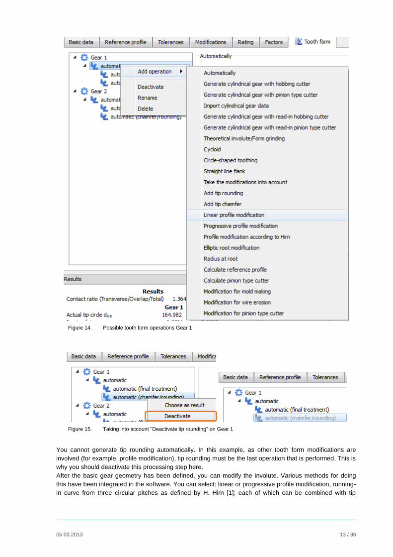
Figure 14. Possible tooth form operations Gear 1
Figure 15. Taking into account "Deactivate tip rounding" on Gear 1
You cannot generate tip rounding automatically. In this example, as other tooth form modifications are
involved (for example, profile modification), tip rounding must be the last operation that is performed. This is
why you should deactivate this processing step here.
After the basic gear geometry has been defined, you can modify the involute. Various methods for doing
this have been integrated in the software. You can select: linear or progressive profile modification, running-
in curve from three circular pitches as defined by H. Hirn [1]; each of which can be combined with tip

05.03.2013 14 / 36
chamfer or tip rounding. In this case, you must specify the correction height (diameter at which the
correction begins) and the tip relief. Each value has a sizing function which proposes optimum values based
on the profile contact ratio, accuracy grade, material type (plastic or metal), stiffness and load. By modifying
the "Factors for tip rounding" you can even specify the shape of the curve (in the "Progressive profile
modification" option)!
In a progressive profile modification, you can improve the length of contact and the local lubrication
properties compared to those achieved by a linear profile modification. The formulae for these profile
modifications are defined as follows:
Linear correction: s(r) = Ca * r /rK
Progressive correction: s(r) = Ca * (r / rK)Exp
s Profile relief (tooth thickness modification)
r Radius of any point on the tooth form
Ca Profile relief at the tip circle
r ra – r
rK ra – raK
ra Tip circle radius
raK Radius, at which the correction begins
Exp = Factor/5
Factor: Range 1-20, usually in the range 5-10
(you can input your own value here)
Figure 16. Types of profile modification
Click the sizing button to the right of the "Modification starting at diameter" input field to obtain a
reasonable suggestion for the beginning and size of the tip relief.
Figure 17. Suggested tip relief
If the gear is to be manufactured by molding processes (injection molding or sintering), it is essential that all
the corners are rounded. You can input the rounding radius at the tip independently of which profile

05.03.2013 15 / 36
modification you select. You can also select the "Add tip rounding" option for the rounding radius at the
tip.
Figure 18. Add tip rounding
You will find the best factor by trial and error. You can view the tooth contact and tooth form in greater detail
by opening the "Meshing" window in the screen (marking in the bottom right of the window).
To compare the different settings you make when modifying the tooth form, save the last tooth form you
calculated as shown in Figure 4.
Figure 19. Comparing tooth form modifications
First, go to the main screen and click on the "Tooth form" tab. In the saved, active calculation, the
"Progressive profile modification" calculation step had 10 as its "Factor for tip rounding". In the "Add
tip rounding" calculation step it had a "Tip rounding" of r=2mm. The calculation is run again, but this time
the "Factor for tip rounding" is 18 and the "Tip rounding" is r=1mm.
2.7 Optimizing the tooth root
The fatigue safety factor can be significantly improved by using a large radius at the transition from the
involute in the root filet. If gears are manufactured by a hobbing process, it is sometimes difficult to achieve
optimum rounding even when using tools with well rounded tips. However, by making a suitable
modification (below the usable root diameter) you can greatly improve the safety factor.
This modification can be VERY useful if you want to eliminate undercut from the tooth form (see next
figure).

05.03.2013 16 / 36
The KISSsoft system can also perform this modification automatically.
You input und calculate optimized tooth root rounding as part of the tooth root calculation by clicking "Elliptic
root modification" and then entering data exactly as you do for tip reliefs as described in 2.6.
Figure 20. Root form without (light turquoise [cyan], with undercut) and with (dark blue) optimization
Important: If used in combination with a running-in curve or tip rounding on the counter gear, the start of
root rounding can also be applied above the arithmetic root form circle. If this happens, it is essential you
check the meshing (see next section).
2.8 Checking the meshing
After you have optimized the tooth form, we strongly recommend you check the precision of the gear
meshing. The contact between the gears should always be in the area of the actual involute. A crash
between the teeth, especially from the tip of the driving gear to the foot of the driven gear, can cause a
great deal of damage. You should perform the check using the minimum center distance value (and, for
safety reasons, also with the maximum center distance). You can input the center distance directly in the
screen.
The "Check for collisions" function is very useful if you need to check if the meshing is correct. Click this
checkbox to activate the collision check. Then position the flank to the right or to the left by clicking the
appropriate icon "Flank to the left or right". A black square shows you if the flanks touch each
other. If a collision occurs, this square is red.

05.03.2013 17 / 36
Figure 21. Activating collision check
Click the "Properties" icon to display the Settings graphic on the right so you can enable the collision
check.
Figure 22. Collision check
"Crash" Correct contact
05.03.2013 18 / 36
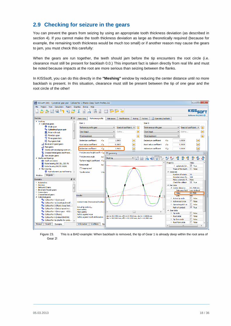
2.9 Checking for seizure in the gears
You can prevent the gears from seizing by using an appropriate tooth thickness deviation (as described in
section 4). If you cannot make the tooth thickness deviation as large as theoretically required (because for
example, the remaining tooth thickness would be much too small) or if another reason may cause the gears
to jam, you must check this carefully:
When the gears are run together, the teeth should jam before the tip encounters the root circle (i.e.
clearance must still be present for backlash 0.0.) This important fact is taken directly from real life and must
be noted because impacts at the root are more serious than seizing between the flanks.
In KISSsoft, you can do this directly in the "Meshing" window by reducing the center distance until no more
backlash is present. In this situation, clearance must still be present between the tip of one gear and the
root circle of the other!
Figure 23. This is a BAD example: When backlash is removed, the tip of Gear 1 is already deep within the root area of
Gear 2!

05.03.2013 19 / 36
3 Strength calculation
3.1 Introduction
When designing and optimizing gears, it is especially important that you calculate the root, flank and wear
safety factors for the projected service life of the gear.
Just like steel gears, the material property values for plastic gears (root resistance and flank strength)
depend greatly on the number of cycles. They are also greatly influenced by temperature and the type of
lubrication (oil, grease or dry).
Whereas only a single value is needed to calculate the tooth root strength of a steel gear (for example,
tooth root fatigue strength [Flim] for 17 CrNiMo6: 525 N/mm2), you need several diagrams for plastic gears.
This data is stored in the KISSsoft system in separate diagrams for oil, grease lubrication or dry run. This
data is processed automatically in the calculation. This means you can easily modify material data yourself.
You will find more detailed information in our manual, especially in the "Materials for gears", "Plastic as
specified in VDI 2545 …", "Plastics" sections.
3.2 Input your own data for plastics
The KISSsoft materials database already contains data about a few plastics. If you already know the
plastics data, you can save it to the KISSsoft database using the method described below. The example
here uses the "POM" material that is already present:
To open the database tool, click on "Extras“ -> "Data base tool", open the materials database, and
enable data for gear calculation:
Figure 24. Opening the example analysis

05.03.2013 20 / 36
Before you can generate a new material, it must be made available to the materials database. Click
"Material basic data" to define this basic data. Then click [Edit] to open the appropriate database tool.
Click "+" to generate a new data record so you can edit it. If you have already selected a material, this data
is transferred to the new data record and a new material description is created. You can then modify any of
the fields as required.
Figure 25. Generating a new data record
Click [OK] to confirm your entries and close the "Edit entry" menu to return to the database tool. Then click
[Save] to save the data. A message then appears to tell you that you have successfully modified the
database.
Figure 26. Database with a new data record that has been successfully changed and saved
The next sections use the material POM (already present in KISSsoft ), to show you which entries are
required. These are the "Material basic data" and the module-specific data, in this case, for "Material
Gears"
Figure 27. "Material basic data" - Module-specific data "Material Gears" for plastic

05.03.2013 21 / 36
The most important information is the entry under "File for Woehler line", shown by the marking in Figure
27. This is where you input the name of the file in which the temperature and lubricant dependent data is
stored. You should store this file in the installation folder (usually C:\Programs\KISSsoft-03-2012\ext\dat):
Figure 28. Storing your own plastics data
You can now store the material data you are about to input in its own file (you can give this file any name
you like). The best way to do this is to copy an existing plastic file (for example, the Z014-100.DAT file for
POM), rename it and then edit it as required.
Extract from Z014-100.DAT (for POM): Young's modulus
(One-dimensional table with Young's modulus, dependent on temperature)
:TABLE FUNCTION Young's modulus INPUT X ToothTempRoot TREAT LINEARDATA -20 0
20 40 60 80 100 120 4400 3950 3500 2950 2400 1800 1400
950
END
Extract from Z014-100.DAT (for POM): Flank strength with oil lubrication
(Two-dimensional table with sig.Hlim dependent on temperature: Columns and load cycles: lines)
-- Data for flank strength with oil lubrication
-- From Niemann, diagram 22.4/4, for PA66, oil lubrication
:TABLE FUNCTION FlankenSigHNOel
INPUT X ToothTempFlank TREAT LINEAR
INPUT Y Load change TREAT LOG
DATA
20 40 60 80 100 120
0 120 115 108 99 91 76
1E5 120 115 108 99 91 76
1E6 95 90 85 78 68 57
1E7 70 67 63 58 50 40
1E8 52 50 47 44 37 28
1E9 45 42 40 38 32 25
1E10 43 41 38 36 30 24
1E11 43 41 38 36 30 23
1E99 43 41 38 36 30 23
END

05.03.2013 22 / 36
3.3 Strength calculation with consideration of effective tooth form
The calculations of the root strength according to the methods in the VDI 2545, DIN 3990, ISO 6336 or
AGMA 2001 standards use a simplified model for calculating the root stress, in which the stress is
calculated for a nominally defined cross section (at a point of the 30 degree tangent on the root filet in DIN
or ISO). However, for gears with a pressure angle that varies greatly from 20 degrees or with verified root
rounding (see below), this cross section can be a long way from the cross section that is subject to the
greatest load. The "Graphical method" used in KISSsoft (according to the procedure described by Obsieger
in "Die Konstruktion") therefore performs the calculation, exactly in accordance with the corresponding
formulae used in the selected calculation method (YF and YS as specified in DIN, ISO, AGMA), in
approximately 50 cross-sections in the entire root area from the mid tooth depth to the root, and can
therefore determine which cross-section has the greatest bending stress. This data is then used in the
calculation. This gives a much more accurate calculation procedure which can also be used to calculate
non-involute tooth forms. For more information, refer to the relevant section in this manual.
To activate this "Graphical method" in KISSsoft: Go to the "Rating" tab and click the [Details] button on the
far right of the screen. This opens a drop down list under "Form factors YF, YS" in which you select "Using
graphical method".
Figure 29. Activating strength calculation using the graphical method
Now, each calculation will first automatically calculate the tooth form and derive YS and YF from it.
You can also display tooth root strain at the tooth root in the KISSsoft system. To do this, enter the required
settings in the "Contact analysis" tab and then run the calculation.

05.03.2013 23 / 36
Figure 30. Calculating the contact analysis
The current status of the calculations is displayed whilst the calculation is actually running.
Figure 31. Progress of the contact analysis calculation
You can then select the graphic you require from "Graphics" "Contact analysis", as in our example, the
normal force curve and normal force distribution as well as the tooth root stress curve.

05.03.2013 24 / 36
Figure 32. Normal force curve of a meshing using the example given in the "CylGearPair 2" file

05.03.2013 25 / 36
Figure 33. ´Tooth root stresses, progression in the root area of Gear 1
4 Defining the Tooth Thickness Deviation
4.1 Introduction
In the precision engineering industry, the relative deviations (allowance/tooth thickness) are usually much
higher for gears with module 1.0 or greater. If the relative center distance tolerance is large, and the
accuracy grade is low, you must select a deviation that is large enough to prevent the gears from seizing
during operation. In addition, many plastics have a tendency to absorb water over time and to swell up.
Experience has shown that it is a good idea to determine the necessary deviation first when you start
designing the gear. There is no point in optimizing a tooth form in great detail (as described below) and then
finding out later on that the excessively large deviation will "devour" the carefully optimized tooth thickness
at the tip!
Use the method specified in DIN3967 to define the deviation. To do this, you must already know the
operating temperatures and the thermal expansion coefficients of the gears and their housing. You must
also take the swelling into consideration. Here, polyamide is the most critical plastic (swells up to 2% due to
water absorption).
4.2 Calculating operating backlash
KISSsoft provides an example file of a plastic gear calculation called "CylGearPair 5". Open this file in the
helical gear calculation module:
Here you must note the selected tolerances for Gear 1, Gear 2 and the Center distance:
Figure 34. Preselected tolerances for Gear 1, Gear 2 and Center distance
Before you then run the operating backlash calculation, you must click "Σ" (calculate) to calculate the
intermeshing. Then click on the "Operating backlash" tab to calculate the operating backlash:
Influence of manufacturing accuracy
(axis alignment)
Influence of temperature on
expansion of the housing and gear
bodies
Select material for housing

05.03.2013 26 / 36
Figure 35. Settings for calculating operating backlash.
This example "CylGearPair 5", is defined so that the gears will seize during operation. When you calculate
the operating backlash, these warning messages will appear:
Figure 36. Error messages: "Gears jam" warning message: Tooth tips collide
Click the button to the right of (create report ) to display this report:
Results:
Center distance change by:
Warming (mm) [DaC] 0.026 Casing
(mm) [DaW] -0.247 Gears
Change to backlash due to:
Center distance tolerance (mm) [Dja.e/i] 0.012/-0.012
Swelling due to water absorption (mm) [DjQ] 0.000
Warming (mm) [Djtheta] -0.170
Axes not parallel (mm) [DjSigmabeta] -0.006
Individual intermeshing variations (mm) [DjF] -0.015
Theoretical backlash (reference circle)
- Circumferential backlash
(min.) (mm) [jt.i] 0.112
(max.) (mm) [jt.e] 0.206
Theoretical backlash (pitch circle)
- Circumferential backlash
(min.) (mm) [jtw.i] 0.113
(max.) (mm) [jtw.e] 0.207
Backlash reduction
- Circumferential backlash
(min.) (mm) [jtwa.i] 0.100
(max.) (mm) [jtwa.e] 0.200
Lowest operating backlash
- Temperature combination
Gear body temperature (°C) [TR] 50.00
Case body temperature (°C) [TC] 50.00
- Circumferential backlash
(min.) (mm) [jtwop.i] -0.070
(max.) (mm) [jtwop.e] 0.030
- Normal backlash
(min.) (mm) [jnwop.i] -0.066
(max.) (mm) [jnwop.e] 0.028

05.03.2013 27 / 36
- Radial backlash
(min.) (mm) [jrwop.i] -0.086
(max.) (mm) [jrwop.e] 0.037
- Angle of rotation for fixed Gear 1
(min.) (°) [Dphit.i] 0.0000
(max.) (°) [Dphit.e] 0.0294
Figure 37. Extract from the operating backlash calculation report
The negative values for circumferential backlash show that the gear pair will jam.
4.3 Increasing operating backlash
In the worst case, the circumferential backlash may be -0.070 mm (see the yellow text marked above). To
prevent the gears from seizing, this value must be greater than zero. The software issues a message telling
you the minimum amount by which you should modify the tooth thickness allowance.
Proposed value for the smallest possible tooth thickness allowance (jtw.i = 0):
Tooth thickness allowance (up.) (mm) [Asn.e] -0.090 -0.106
(lower) (mm) [Asn.i] -0.120 -0.146
Figure 38. Suggestion made by the software
To do this, change the tooth thickness deviation (make the teeth thinner). Both gears are reduced by
0.04mm (to increase the circumferential backlash by 0.08mm to ensure it remains positive). To do this, go
to the "Tolerances" tab, set tooth thickness deviation to "Own input“ and increase each circumferential
backlash by 0.04mm (for the lower and the upper allowance of both gears):
Figure 39. Original state (tolerance cd25 as specified in DIN3967)

05.03.2013 28 / 36
Figure 40. Increase to the circumferential backlash for both gears, each by 0.04mm
After this, click (Calculate) to run the meshing again and recalculate the operating backlash – as
described above. This time, no warning appears (because the gears do not jam) and you see a positive
operating backlash in the report:
Smallest operating backlash
- Temperature combination
Gear body temperature (°C) [TR] 50.00
Case body temperature (°C) [TC] 50.00
- Circumferential backlash
(min.) (mm) [jtwop.i] 0.010
(max.) (mm) [jtwop.e] 0.111
- Normal backlash
(min.) (mm) [jnwop.i] 0.010
(max.) (mm) [jnwop.e] 0.104
- Radial clearance
(min.) (mm) [jrwop.i] 0.013
(max.) (mm) [jrwop.e] 0.136
...
Figure 41. Extract from the operating backlash calculation report. The operating backlash is now positive
5 Calculating the injection mould
5.1 Introduction
The theoretical tooth form which has been optimized as described above is calculated by the KISSsoft
system, using the mid-value of the tooth thickness deviations. The results in the required tooth form, which
can then be transferred to a CAD program via the DXF or IGES interface. You can, for example, use this
contour to monitor gears manufactured using a projection process.
You can also mathematically define the injection mould. When plastic gears are manufactured using an
injection process, a certain amount of shrinkage occurs as the plastic solidifies. The injection mould is
therefore designed to be slightly larger in order to compensate for this shrinkage. To achieve this, the tooth
form is expanded both radially and tangentially. Radial expansion gives an aspect ratio change in the radial
direction (i.e. each point on the tooth outer contour is shifted in a straight line from the center point).
Tangential expansion causes a thickening of the tooth and a corresponding reduction in the tooth gap. To
calculate the injection mold in the KISSsoft system, you can predefine the required radial expansion at the
tooth tip and at the root as well as the tangential expansion as a percentage.

05.03.2013 29 / 36
5.2 Modifying the injection mold to compensate for shrinkage
To enable these modifications, click the "Tooth form" tab to open the tooth form calculation. Then add the
other operations to the operation already enabled in that tab "automatic (Rack)".
Figure 42. Tooth form calculation with modifications for molding
You can now input the radial and tangential expansion. The resulting tooth form is now calculated with
and can be displayed with "2D":

05.03.2013 30 / 36
Figure 43. Calling the display of the gear pair
Note: Before you can display the modified tooth form, you must enable "Modification for mold
making" ("Choose as result").
The icon color yellow shows that this operation is used for the display!

05.03.2013 31 / 36
Figure 44. Display of the gears, increased by the pre-defined shrinkage
If you want to use these tooth forms to manufacture molds, it is a good idea to export them individually.
Under "Permissible deviation" you can input a value * to specify the maximum deviation permitted for the
tooth form and also which type of approximation you want to achieve. You can then open the "2D
geometry" graphics window directly below to display the tooth forms of Gear 1 and Gear 2.
Figure 45. Permissible deviation; Open graphics window

05.03.2013 32 / 36
Figure 46. Calling the display of the tooth form for a single gear and exporting the tooth form in DXF or IGES format
It is essential you check the title of the graphic: The left-hand screen shows the expanded tooth form
(shown with a mold modification). In the right-hand screen you also see the UN-modified tooth form shown
in "black". You use this procedure to display the tooth form expanded by the specified shrinkage as
specified in Figure 46.
5.3 Display the eroding wire / spark gap
In addition, when you calculate the injection mold you can also take the spark gap into account when you
define the eroding wire. During the eroding process, the spark gap is the clearance between the eroding
wire and the material that will form the mold. The eroding wire must therefore be thinner than the spark gap.
For eroding wires used to form teeth, the tooth will be correspondingly thinner. If the mold is formed by wire
erosion, you can use the same procedure (spark gap plus wire radius) to also define the feed path of the
wire.
Add the "Modification for wire erosion" option to ensure that the spark gap can be taken into consideration.
Note: To display the modified tooth form, you still need to enable the "Modification for wire erosion" option
("Choose as result")
05.03.2013 33 / 36
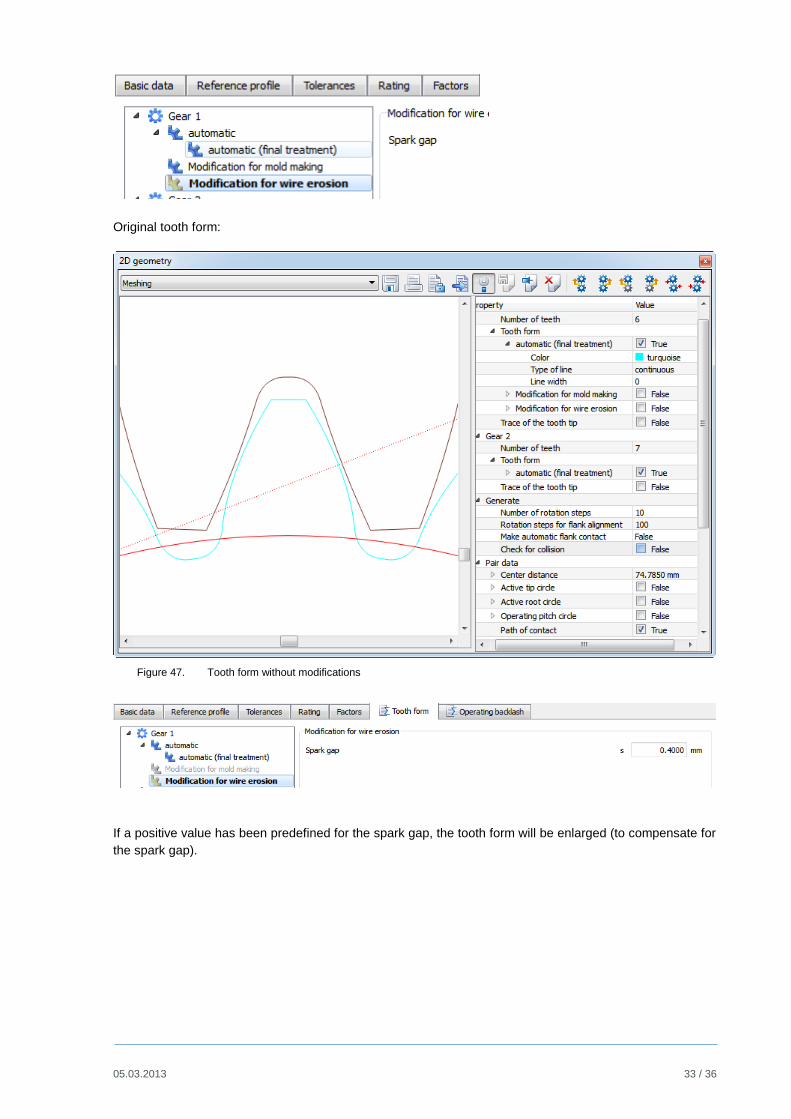
Original tooth form:
Figure 47. Tooth form without modifications
If a positive value has been predefined for the spark gap, the tooth form will be enlarged (to compensate for
the spark gap).

05.03.2013 34 / 36
Figure 48. Tooth form shown with a 0.4 mm spark gap
If a negative value has been specified for the spark gap, the tooth form is displayed as if an eroding wire
had been passed under the displayed mould.
Figure 49. Tooth form shown with a -0.4 mm spark gap
05.03.2013 35 / 36
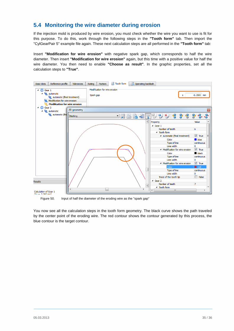
5.4 Monitoring the wire diameter during erosion
If the injection mold is produced by wire erosion, you must check whether the wire you want to use is fit for
this purpose. To do this, work through the following steps in the "Tooth form" tab. Then import the
"CylGearPair 5" example file again. These next calculation steps are all performed in the "Tooth form" tab:
Insert "Modification for wire erosion" with negative spark gap, which corresponds to half the wire
diameter. Then insert "Modification for wire erosion" again, but this time with a positive value for half the
wire diameter. You then need to enable "Choose as result". In the graphic properties, set all the
calculation steps to "True".
Figure 50. Input of half the diameter of the eroding wire as the "spark gap"
You now see all the calculation steps in the tooth form geometry. The black curve shows the path traveled
by the center point of the eroding wire. The red contour shows the contour generated by this process, the
blue contour is the target contour.
05.03.2013 36 / 36
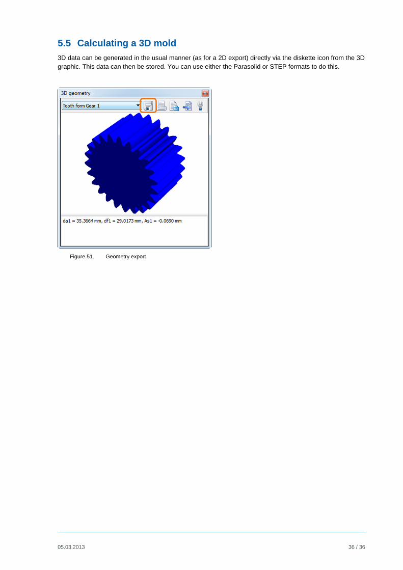
5.5 Calculating a 3D mold
3D data can be generated in the usual manner (as for a 2D export) directly via the diskette icon from the 3D
graphic. This data can then be stored. You can use either the Parasolid or STEP formats to do this.
Figure 51. Geometry export