topo 3-dimensional system brochure ic438
TRANSCRIPT

Make Waves
Topo™
3-Dimensional System

Topo panels are offered in translucent and opaque to work with existing lighting and complement any color palette. Optional pre-engineered utility circles accommodate additional lighting and pro-vide utility access.
1 Topo 3-Dimensional System
User’s Guide
Pages
Understand Your System 3 Overview
Components
Accessories
Design Your System 9 Design Rules
Design Tools
Specify Your System 12 Application Guide Specifications
For More Information Technical Service 800 USG.4YOU
Web Site www.usg.com
1 Topo 3-Dimensional System

System Profile The Topo 3-Dimensional System is available in 8" total depth.
System Components Infill Panels
The 2 x 2 pre-formed polycarbonate panels fit easily into the narrow-profile Donn Brand Topo Suspension
System. The panels are installed in a series of four-panel modules to create rolling 3-dimensional ceiling
topographies. The smooth-surfaced panels are available in translucent white and opaque white.
Donn Brand Topo Suspension System
The narrow-profile (9/16 wide) Donn Brand Topo Suspension System is offered in flat white to complement
panel finishes. The extruded aluminum suspension system can also be custom-painted. It features an
integral clip on each cross-tee end, providing plug-in, positive-lock insertion for quick and easy
installation without tools.
Topo Edge Trim
The Topo 3-Dimensional System can be finished with 2-1/4-high trim in flat white or custom colors.
Utility Circles
Panels can be ordered with optional utility circles to integrate independently supported lighting and utilities.
The 4 diameter utility circles can be positioned either at the high or low points of suspension system
intersections, or centered on specific panels. (See Design Rules, p. 9.)
2 Topo 3-Dimensional System
Topo™
3-Dimensional System
2 Topo 3-Dimensional System
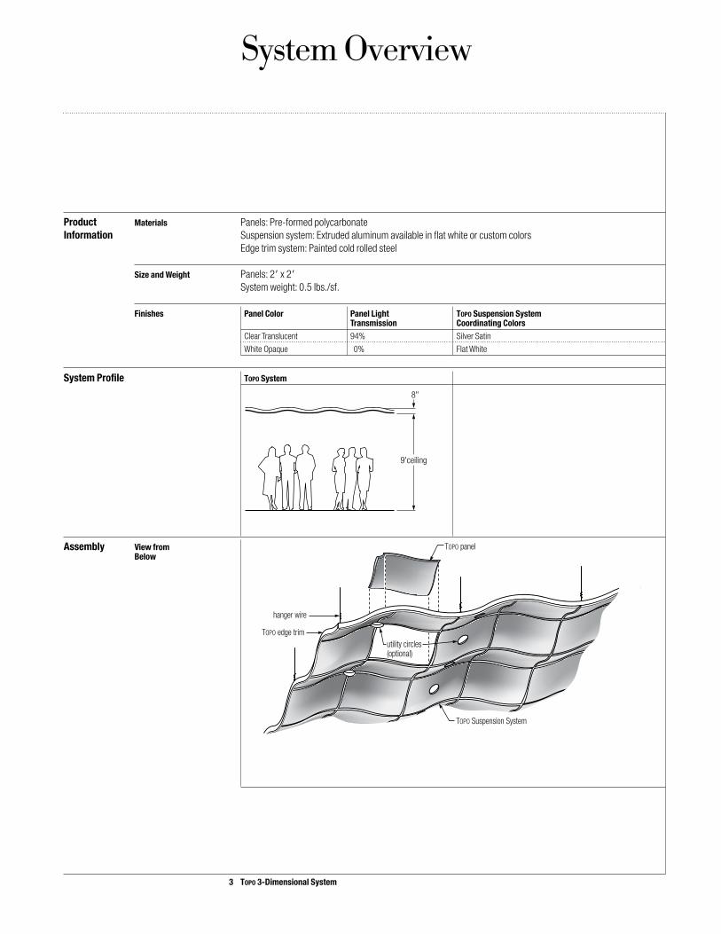
System Overview
ProductInformation
System Profile Topo System
Assembly View from Below
Materials Panels: Pre-formed polycarbonate Suspension system: Extruded aluminum available in flat white or custom colors Edge trim system: Painted cold rolled steel
Size and Weight Panels: 2 x 2 System weight: 0.5 lbs./sf.
Finishes Panel Color Panel Light Topo Suspension System Transmission Coordinating Colors Clear Translucent 94% Silver Satin
White Opaque 0% Flat White
9'ceiling
8"
TOPO panel
hanger wire
TOPO Suspension System
TOPO edge trimutility circles(optional)
3 Topo 3-Dimensional System

4 Topo 3-Dimensional System
System Components
Infill Panels Field Panel CAD Block Isometric View from Below (or Standard Panel)
Panel with Utility Circle Formed at High Point
Panel with Utility Circle Formed at Low Point
Panel with Utility Circle Formed in Center with a 3/4 High Upward Return Leg
L
H
8
L
H
8EHL
L
H
8EHH
L
H
8CH
3/4"

5 Topo 3-Dimensional System
Donn Brand Topo The narrow profile (9/16 wide) Donn Brand Topo Suspension System is offered in flat white.Suspension System The extruded aluminum suspension system can be custom painted. The system features an integral clip on each
cross-tee end, providing plug-in, positive-lock insertion for quick and easy installation without tools.
Grid Panel Profile High Low
Cross Tee 2 Cross Tee
4 Cross Tee (Up) 4 Cross Tee (Down)
Main Tee 8 Main Tee
Main Tee Splice Plate
9/16"
11/4"

6 Topo 3-Dimensional System
System Accessories
Edge Trim Topo System ceilings can be finished with optional 2-1/4-high edge trim, laser cut to match each main tee segment. The trim system consists of integral attachment clips, corner caps and fascia clips.
Detail
Utility Circles Optional 4 diameter panel utility circles can be positioned either at the high points or low points of the suspension system intersections, or centered on panels. (For more details, see Design Rules, p. 9.)
4 Diameter Utility Circle at Center of Panel 4 Diameter Utility Circle at High Point with Cross Tee Attached
Utility Circle Cross Tee for Utility Circle at Low Point Cross Tee for Utility Circle at High PointCross Tees
3/4"

7 Topo 3-Dimensional System
System Profiles
The Topo 3-Dimensional System is 5 inches from the top-most point to the bottom-most point. The system consists of pre-formed polycarbonate infill panels installed in a series of four-panel modules to create a rolling 3-dimensional ceiling topography.
Topo System Topo System creates a smooth, gently rolling ceiling with clearly defined dimension and form. It is ideal for environments where subtle ceiling undulation is desired.
Plan View Using Topo CAD Blocks
L
H8E
HH
L
H
8EHH
L
H
8EHH
L
H
8EHH
L
H
8EHH
L
H
8EHH
L
H
8EHH
L
H
8EHH
L
H
8EHH
L
H
8EHH
L
H
8EHHL
H
8EHH
L
H
8EHH
L
H
8EHH
L
H
8EHH
L
H
8EHH
L
H
8EHH
L
H
8EHH
L
H
8EHHL
H
8EHH
L
H
8
L
H
8
L
H
8
L
H8
L
H
8
L
H
8
L
H
8
L
H8
L
H
8
L
H8
L
H
8
L
H8
L
H
8
L
H
8
H H
L
H
8
L
H
8
H H
L
H
8
L
H8
H H
L
H
8
L
H
8
9'ceiling
8"
L
H
8EHH
L
H
8EHH
L
H
8EHH
L
H
8EHH
L
H
8EHH
L
H
8EHH
L
H
8EHH
L
H
8EHH
L
H
8EHH
L
H
8EHH
L
H8EHH
L
H
8EHH
L
H
8EHH
L
H
8EHH
L
H
8EHH
L
H
8EHH
L
H
8EHH
L
H
8EHH
L
H8EHH
L
H
8EHH
L
H
8
L
H
8L
H8
L
H
8
L
H
8
L
H
8
L
H
8
L
H
8
L
H
8
L
H
8
L
H
8
L
H
8L
H
8
L
H
8
H H
L
H
8
L
H
8
H H
L
H
8
L
H
8
H H
L
H
8
L
H
8
9'ceiling
8"
Elevation

8 Topo 3-Dimensional System
Lighting and The Topo 3-D System is not designed to carry ceiling utilities. All lighting and utilities must be independently Utilities supported.
Utility Circles The 4-diameter Topo utility circles may be positioned in three locations: – At the intersection of two down cross tees. – At the intersection of two up cross tees. – In the center of Topo infill panels.
Utility Circle Locations Low Points(Viewed from Above)
High Points
Design Rules
Following are basic design rules covering the selection of Topo 3-Dimensional System panels and the positioning of utility circles within the ceiling system.
main tee
main tee
main tee
main tee
main tee
main tee
Option 1 - All Low Holes
main tee
main tee
main tee
main tee
main tee
main tee
Option 2 - All High Holes

9 Topo 3-Dimensional System
Design Rules
Utility Circle Locations Panel Center(Viewed from Above)
Adding Rows Additional rows of main tees may be specified to shift cross tee intersections as neededof Main Tees Shifting Cross Tee Intersections
main tee
main tee
main tee
main tee
main tee
main tee
main tee cross tee row
cross tee rows
cross tee rows
cross tee rows
Option 3 - Low and High Hole Combination
main tee
main tee
main tee
main tee
main tee
main tee
Option 4 - Panel CenterNote: Utility circles on individual panels can be located only at panel centers.

10 Topo 3-Dimensional System
Restrictions Utility circles may not be placed: – At the intersection of a main tee and a cross tee. – In the center of any tee. – At more than one location on a single panel. – At the perimeter of the Topo assembly.
Not Allowed
main tee
main tee
main tee
main tee
main tee
main tee
main tee
Rules for design of light holes
intersection of main tee and cross tee
center of a teemore than one location on a single panel
perimeter ofTOPO assembly

11 Topo 3-Dimensional System
Design Tools
The Topo 3-Dimensional System can be designed using three interactive design tools: Topo CAD Blocks, the Topo Online Designer or the USG Design Wizard.
Topo CAD Topo DXF Blocks offers designers a simple, time-saving means for creating Topo 3-Dimensional System designs Blocks in most CAD systems. The blocks, which can be downloaded for free from the Online Tools section of the USG web site (www.usg.com), are compatible with nearly all CAD systems.
Topo System
L
H
8
L
H
8EHL
L
H
8EHH
L
H
8CH

12 Topo 3-Dimensional System
Application Guide SpecificationsSection 09550 – 3-Dimensional Ceiling Systems
Part 1: 1.1 A. Drawings and general provisions of the Contract, including General and Supplementary Conditions and Division 1 General Related Documents Specification Sections, apply to this Section.
1.2 A. This Section includes 3-dimensional ceiling panels and extruded aluminum suspension systems. Summary B. Related Sections include the following: 1. Division 9 – Section 09250 – Gypsum Board 2. Division 9 – Section 09511 – Acoustical Panel Ceilings 3. Division 15 Sections – Mechanical 4. Division 16 Sections – Electrical
1.3 A. Samples for Initial Selection: Manufacturer’s color charts showing the full range of colors available for units. Submittals B. Samples for Verification: For each type of exposed finish required, prepared on Samples of size indicated below
and of same thickness and material indicated for the Work. 1. 3-Dimensional Ceiling Panels: Set of Samples of each type, finish, and color. Exposed Suspension System Members, Moldings, and Trim: Set of 12 inch long Samples of each type, finish, and color. C. Qualification Data: For firms and persons specified in “Quality Assurance” Article to demonstrate their capabilities
and experience. Include lists of completed projects with project names and addresses, names and addresses of architects and owners, and other information specified.
1.4 A. Installer Qualifications: An experienced installer who has completed 3-dimensional ceiling systems similar in Quality Assurance material, design, and extent to those indicated for this Project and whose work has resulted in construction with
a record of successful in-service performance. B. Source Limitations for 3-Dimensional Ceiling Systems: Obtain 3-dimensional ceiling systems from one source
with resources to provide products of consistent quality in appearance and physical properties. C. Preinstallation Conference: Conduct conference at Project site to comply with requirements in Division 1 Section
“Project Meetings.”
1.5 A. Environmental Limitations: Do not install 3-dimensional ceiling systems until spaces are enclosed and weather Project Conditions proof, wet-work in spaces is complete and dry, work above ceilings is complete, and ambient temperature and
humidity conditions are maintained at the levels indicated for Project when occupied for its intended use.
1.6 A. Furnish extra materials described below that match products installed and that are packaged with protective Extra materials covering for storage and identified with labels describing contents. 1. 3-Dimensional Ceiling Panels: Furnish quantity of full-size units equal to [%] percent of amount installed.

13 Topo 3-Dimensional System 13 Topo 3-Dimensional System
Part 2: 2.1 A. Products: Subject to compliance with requirements, provide one of the products indicated for each designation Products Products and in the 3-Dimensional Ceiling System Schedule at the end of Part 3.
Manufacturers
2.2 A. Panel Type: Lay-in pan. 3-Dimensional B. Panel Material: pre-formed polycarbonate.
Ceiling Panels C. Panel Thickness: Not less than 0.040 inches.
D. Panel Size: 24 by 24 inches. E. Panel Finish: Smooth-surfaced to match color indicated by product designation. F. 3-Dimensional Ceiling System Characteristics: Comply with requirements indicated in the 3-Dimensional Ceiling
System Schedule at the end of Part 3.
2.3 A. Metal Suspension System Standard: Provide ceiling manufacturer’s standard metal suspension systems of Metal Suspension materials and finishes indicated that comply with applicable ASTM C 635 requirements.
Systems B. Attachment Devices: Size for five times the design load indicated in ASTM C 635, Table 1, Direct Hung, unless
otherwise indicated. 1. Cast-in-Place and Postinstalled Anchors in Concrete: Anchors of type and material indicated below, with holes or
loops for attaching hangers of type indicated and with capability to sustain, without failure, a load equal to five times that imposed by ceiling construction, as determined by testing per ASTM E 488, conducted by a qualified testing agency.
a. Type: Cast-in-place anchors. b. Type: Postinstalled expansion anchors. c. Corrosion Protection: Carbon-steel components zinc plated to comply with ASTM B 633, Class Fe/Zn 5 (0.005
mm) for Class SC service condition (mild). 2. Postinstalled Powder-Actuated Fasteners in Concrete: Fastener system of type suitable for application indicated,
fabricated from corrosion-resistant materials, with clips or other accessory devices for attaching hangers of type indicated, and with capability to sustain, without failure, a load equal to 10 times that imposed by ceiling construc-tion, as determined by testing per ASTM E 1190, conducted by a qualified testing agency.
C. Wire Hangers, Braces, and Ties: Provide wires complying with the following requirements: 1. Zinc-Coated Carbon-Steel Wire: [ASTM A 641] [ASTM A 641M], Class 1 zinc coating, soft temper. 2. Size: Select wire diameter so its stress at three times hanger design load (ASTM C 635, Table 1, Direct Hung) will
be less than the yield stress of wire, but provide not less than 12 gauge wire. D. Hanger Rods: Mild steel, zinc coated or protected with rust-inhibitive paint.
2.4 A. Narrow-Face, Single-Web, Extruded-Aluminum Suspension System: Main and cross runners formed from Extruded-Aluminum extruded aluminum to produce structural members with 9/16-inch- wide faces.
Suspension Systems 1. Face Design: Flat, flush.
2. Face Finish: Painted to match panel finish.

14 Topo 3-Dimensional System
Part 3: 3.1 A. Examine substrates and structural framing to which 3-dimensional ceiling systems attach or abut, with Installer Execution Examination present, for compliance with requirements specified in this and other sections that affect ceiling installation and
anchorage, and other conditions affecting performance of 3-dimensional ceiling systems. 1. Proceed with installation only after unsatisfactory conditions have been corrected.
3.2 A. Coordination: Furnish layouts for cast-in-place anchors, clips, and other ceiling anchors whose installation is Preparation specified in other Sections. B. Measure each ceiling area and establish layout of 3-dimensional ceiling systems. Comply with layout shown on
reflected ceiling plans.
3.3 A. General: Install 3-dimensional ceiling systems to comply with publications referenced below per manufacturer’s Installation written instructions: 1. Standard for Ceiling Suspension System Installations: Comply with ASTM C 636. B. Suspend 3-dimensional ceiling system hangers from building’s structural members and as follows: 1. Install hangers plumb and free from contact with insulation or other objects within ceiling plenum that are not part
of supporting structural or 3-dimensional ceiling system. 2. Where width of ducts and other construction within ceiling plenum produces hanger spacings that interfere with
the location of hangers at spacings required to support decorative channel members, install supplemental suspen-sion members and hangers in form of trapezes or equivalent devices.
3. Secure hangers to structure, including intermediate framing members, by attaching to inserts, eye screws, or other devices that are secure and appropriate for structure to which hangers are attached and for type of hanger involved. Install hangers in a manner that will not cause them to deteriorate or fail due to age, corrosion, or elevated temperatures.
4. Do not support 3-dimensional ceiling system directly from permanent metal forms or floor deck. Fasten hangers to powder-actuated fasteners, or drilled-in anchors that extend through forms into concrete.
5. Do not attach hangers to steel deck tabs. 6. Do not attach hangers to steel roof deck. Attach hangers to structural members. 7. Space hangers not more than 48 inches o.c. along each member supported directly from hangers, unless other-
wise indicated.
3.4 Clean, exposed surfaces of 3-dimensional ceiling systems. Comply with manufacturer’s written instructions for Cleaning cleaning and touchup of minor finish damage. Remove and replace 3-dimensional ceiling system components that cannot be successfully cleaned and repaired to permanently eliminate evidence of damage, including dented
and deformed channels.
3.5 A. 3-Dimensional Ceiling System 3DSC-[#]: Where ceilings of this designation are indicated, provide components 3-Dimensional Ceiling
complying with the following:
System Schedule 1. Products: Topo 3-Dimensional Accent System and Donn Brand Topo Suspension System by USG Interiors, Inc.
2. Topo 3-Dimensional Accent Infill Panels: with panel profile [Ceiling Configuration], [Access Circle Cut at High Point], [Access Circle Cut at Low Point], [Access Circle Centered on Panel], available in [Translucent White], [Opaque White].
3. Donn Brand Topo Suspension System: Extruded-aluminum, narrow profile, 9/16-inch- wide face, offered in coordinated colors to match the panel finish.
4. Cross Tee: [24-inches], [48-inches–Up], [48-inches-Down]. 5. Main Tee: 96-inches. 6. Main Tee Splice Plate. 7. Panel Hold Down Clip: Quick-release clip on cross-tee ends. 8. Edge Trim Pieces: 2-1/4- inches high, painted to match panel finish.

Technical Service
800 USG.4YOUWeb Site
www.usg.comSamples/Literature
888 874.2450Samples/Literature E-mail
[email protected]/Literature/Fax
888 874.2348Customer Service
800 950.3839
Manufactured by USG Interiors, Inc.550 West AdamsChicago, IL 60661
IC438/rev. 3-15© 2015, USG Interiors, Inc.Printed in U.S.A.
NoticeWe shall not be liable for incidental and consequential damages, directly or indirectly sustained, nor for any loss caused by application of these goods not in accordance with current printed instructions or for other than the intended use. Our liability is expressly limited to replacement of defective goods. Any claim shall be deemed waived unless made in writing to us within thirty (30) days from date it was or reasonably should have been discovered. SAFETY FIRST!Follow good safety and industrial hygiene practices during handling and installation of all products and systems. Take necessary precautions and wear the appro - priate personal protective equip-ment as needed. Read material safety data sheets and related lit-erature on products before speci-fication and/or installation.
NoteAll products described here may not be available in all geographic markets. Consult your local sales office or representative for information. TrademarksThe following trademarks used herein are owned by USG Interiors, Inc.: Donn, Topo, USG. AUToCAD is a trademark of AutoDesk, Inc.PatentsPatents pending.