torque reaction systems and posi-control systems
TRANSCRIPT
Torque Reaction systems and Posi-Control systems
E R G O N O M I C S A N D W O R K S T A T I O N S
w w w . d o g a . f r

w w w . d o g a . f r
Pictograms
Com
pact
ness
Healt
h pr
otec
tion
Erro
r pro
ofing
Prod
uctio
n Qu
ality
Impr
oved
erg
onom
icsM
axim
um p
rodu
ctivi
tyHi
gh Q
ualit
y sta
ndar
ds
The rangeTORQUE REACTION ARMS(p.4 to 33)A comprehensive range of torque reaction systems to decrease employee injuries and boost your productivity.
POSI CONTROL SYSTEM(p.34 to 47)Error proofing and sequencing systems for zero fault assembly process.Automation devices management on your assembly line.
BA...C
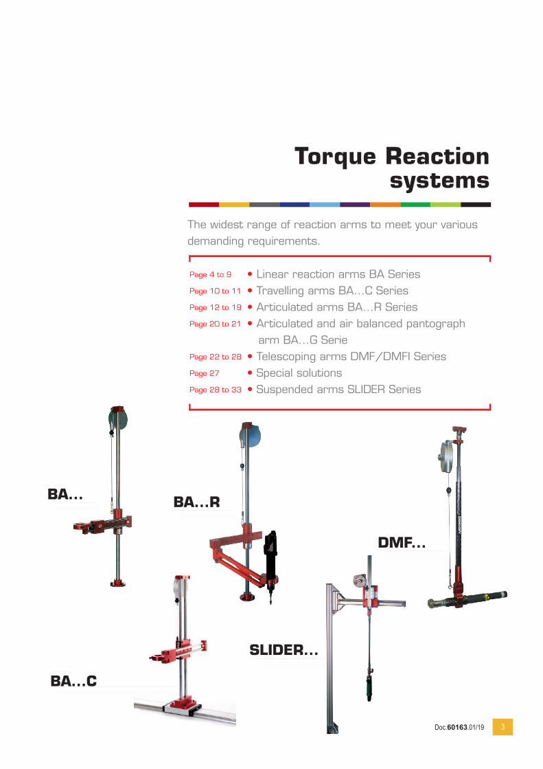
• Linear reaction arms BA Series• Travelling arms BA...C Series• Articulated arms BA...R Series• Articulated and air balanced pantograph arm BA...G Serie• Telescoping arms DMF/DMFI Series• Special solutions• Suspended arms SLIDER Series
Page 4 to 9
Page 10 to 11
Page 12 to 19
Page 20 to 21
Page 22 to 28
Page 27
Page 28 to 33
3
Torque Reaction systems
The widest range of reaction arms to meet your various demanding requirements.
BA... BA...R
SLIDER...
DMF...
Doc.60163.01/19
Linear Arms
BA Series
4
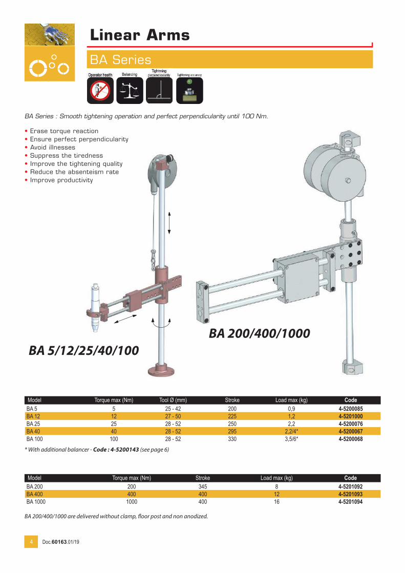
Model Torque max (Nm) Tool Ø (mm) Stroke Load max (kg) CodeBA 5 5 25 - 42 200 0,9 4-5200085BA 12 12 27 - 50 225 1,2 4-5201000BA 25 25 28 - 52 250 2,2 4-5200076BA 40 40 28 - 52 295 2,2/4* 4-5200067BA 100 100 28 - 52 330 3,5/6* 4-5200068
* With additional balancer - Code : 4-5200143 (see page 6)
BA 5/12/25/40/100BA 200/400/1000
BA Series : Smooth tightening operation and perfect perpendicularity until 100 Nm.
• Erase torque reaction• Ensure perfect perpendicularity• Avoid illnesses• Suppress the tiredness• Improve the tightening quality• Reduce the absenteism rate• Improve productivity
Model Torque max (Nm) Stroke Load max (kg) CodeBA 200 200 345 8 4-5201092BA 400 400 400 12 4-5201093BA 1000 1000 400 16 4-5201094
BA 200/400/1000 are delivered without clamp, floor post and non anodized.
Doc.60163.01/19
Linear Arms
BA...TWIN Series
5
BA... TWIN
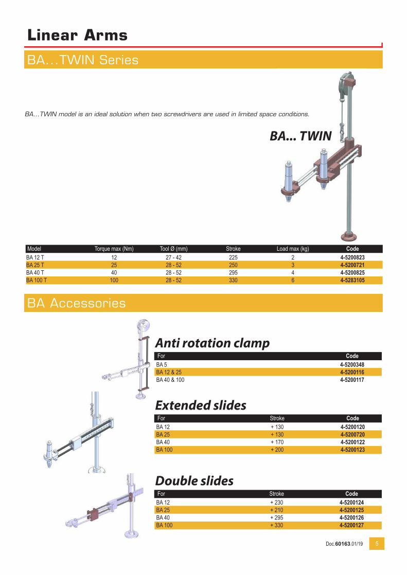
Model Torque max (Nm) Tool Ø (mm) Stroke Load max (kg) CodeBA 12 T 12 27 - 42 225 2 4-5200823BA 25 T 25 28 - 52 250 3 4-5200721BA 40 T 40 28 - 52 295 4 4-5200825BA 100 T 100 28 - 52 330 6 4-5283105
BA...TWIN model is an ideal solution when two screwdrivers are used in limited space conditions.
Anti rotation clampFor CodeBA 5 4-5200348BA 12 & 25 4-5200116BA 40 & 100 4-5200117
Extended slidesFor Stroke CodeBA 12 + 130 4-5200120BA 25 + 130 4-5200720BA 40 + 170 4-5200122BA 100 + 200 4-5200123
Double slidesFor Stroke CodeBA 12 + 230 4-5200124BA 25 + 210 4-5200125BA 40 + 295 4-5200126BA 100 + 330 4-5200127
BA Accessories
Doc.60163.01/19
Linear arms
BA Accessories
6
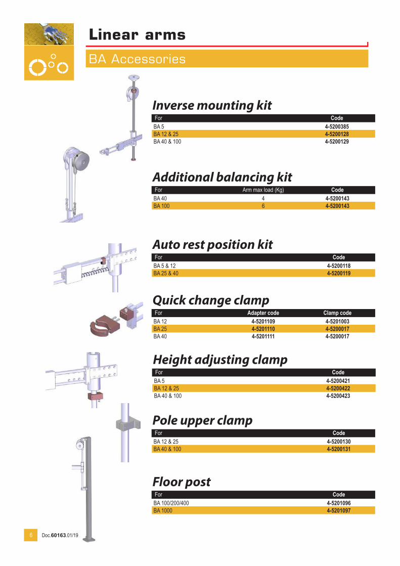
Inverse mounting kitFor CodeBA 5 4-5200385BA 12 & 25 4-5200128BA 40 & 100 4-5200129
Additional balancing kitFor Arm max load (Kg) CodeBA 40 4 4-5200143BA 100 6 4-5200143
Auto rest position kitFor CodeBA 5 & 12 4-5200118BA 25 & 40 4-5200119
Quick change clampFor Adapter code Clamp codeBA 12 4-5201109 4-5201003BA 25 4-5201110 4-5200017BA 40 4-5201111 4-5200017
Height adjusting clampFor CodeBA 5 4-5200421BA 12 & 25 4-5200422BA 40 & 100 4-5200423
Pole upper clampFor CodeBA 12 & 25 4-5200130BA 40 & 100 4-5200131
Floor postFor CodeBA 100/200/400 4-5201096BA 1000 4-5201097
Doc.60163.01/19

Linear arms
BA Accessories
7
Downward Assistance Kitsxxxx
EASY PUSHModel For Pushing force (Kg) Stroke (mm) Type CodeEASY PUSH BA 12 5 125 Pneumatic 4-5200099EASY PUSH BA 25 9 160 - 4-5200102EASY PUSH BA 40 & 100 9 200 - 4-5200103EASY PUSH BA 40 & 100 15 200 - 4-5200144EASY PUSH BA 100 25 200 - 4-5200145EASY PUSH BA 12 5 125 Electric 4-5200838EASY PUSH BA 25 9 160 - 4-5200839EASY PUSH BA 40 & 100 9 200 - 4-5200840EASY PUSH BA 40 & 100 15 200 - 4-5200841EASY PUSH BA 100 25 200 - 4-5200842Easy Push Cable/GX 4-5200843Easy Push Cable/DELVO 4-5200844Cable without connector (for 5/9 kg pushing force) 4-5200845Cable without connector (for 15/25 kg pushing force) 4-5200846U3-D Interface for GX screwdrivers 6-1041888
BAPERModel For Pushing force (Kg) Type CodeBAPER BA 12 5 Pneumatic 4-5200095BAPER BA 25 9 - 4-5200096BAPER BA 40 & 100 9 - 4-5200097BAPER BA 12 5 Electric 4-5200830BAPER BA 25 9 - 4-5200831BAPER BA 40 & 100 9 - 4-5200832BAPER Cable/GX 4-5200833BAPER Cable/DELVO 4-5200834Cable without connector 4-5200835U3-D Interface for GX screwdrivers 6-1041888
Safety kitFor CodeBA 12 & 25 4-5200134BA 40 & 100 4-5200135
The safety kit allows to avoid activation of downward assistance before powerbit gets in contact with the screw.
Electric BAPER kits are delivered without cable.
EASY PUSH kits are delivered without cable.
Downward Assistance Kits will provide you with Extreme Comfort and productivity increase. Ideal for self-tapping applications it requires no effort from the operator. BAPER system features a built-in collect chuck that allows the system to be used at any height. Easy Push system operates only at a preset height by using a mechanical stop that is set along.
Doc.60163.01/19

Linear arms
BA 5 to 100 Dimensions
8
BA DimensionsModel Stroke A B
Min Max C D E F
BA 5 200 222 302 705 65 8,5 78BA 12 225 186 336 805 65 8,5 78BA 25 250 221 396 908 65 8,5 78BA 40 295 260 460 1008 100 8,5 118BA 100 330 315 515 1008 126 10,5 148
stroke
at on
Doc.60163.01/19
Linear arms
BA 200 / 400 Dimensions
9
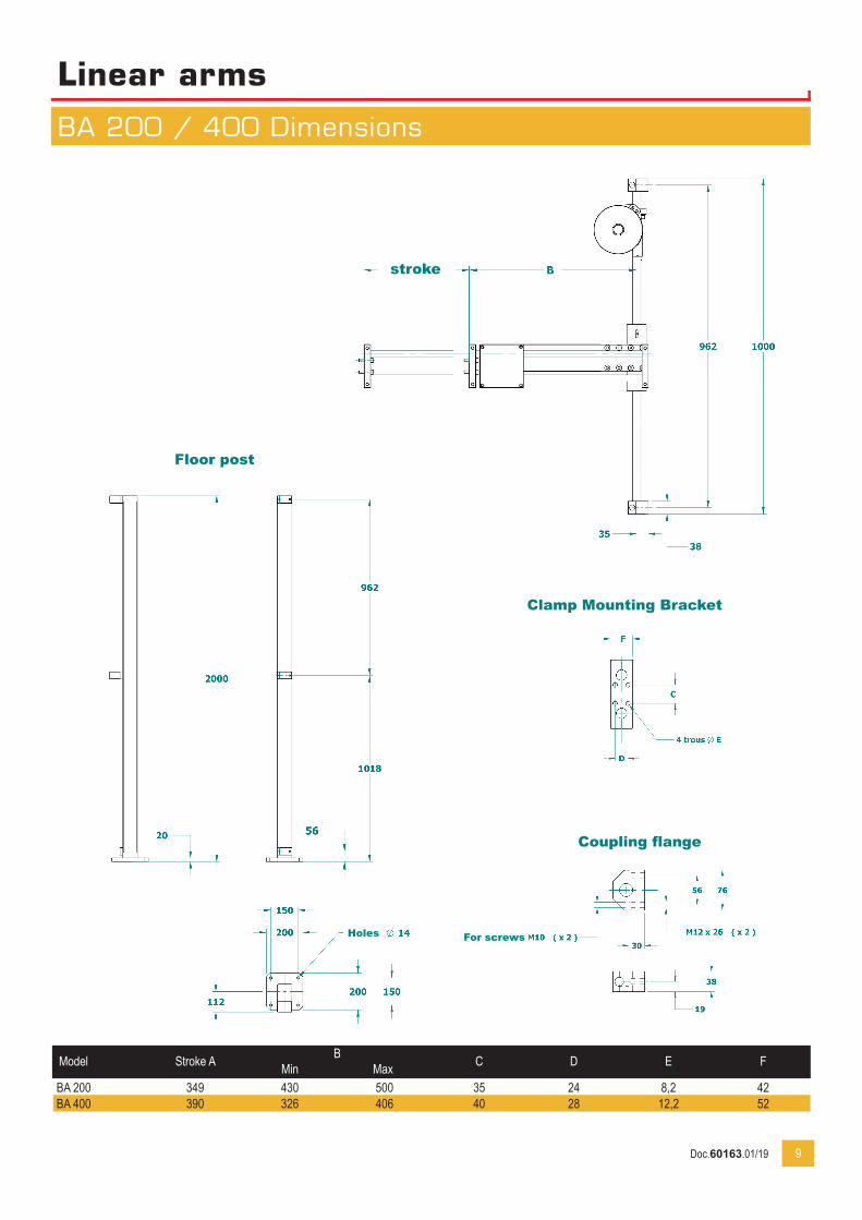
Model Stroke A BMin Max C D E F
BA 200 349 430 500 35 24 8,2 42BA 400 390 326 406 40 28 12,2 52
stroke
Floor post
Clamp Mounting Bracket
Coupling flange
For screwsHoles
Doc.60163.01/19
Travelling arms
BA...C Series
10
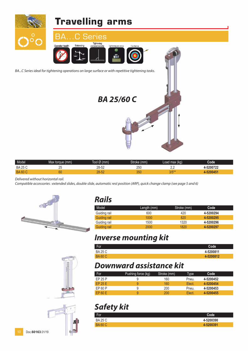
Model Max torque (mm) Tool Ø (mm) Stroke (mm) Load max (kg) CodeBA 25 C 25 28-52 250 2,2 4-5200722BA 60 C 60 28-52 350 3/5** 4-5200451
RailsModel Length (mm) Stroke (mm) CodeGuiding rail 600 420 4-5200294Guiding rail 1000 820 4-5200295Guiding rail 1500 1320 4-5200296Guiding rail 2000 1820 4-5200297
Downward assistance kitFor Pushing force (kg) Stroke (mm) Type CodeEP 25 P 9 160 Pneu. 4-5200452EP 25 E 9 160 Elect. 4-5200454EP 60 P 9 200 Pneu. 4-5200453EP 60 E 9 200 Elect. 4-5200455
For CodeBA 25 C 4-5200390BA 60 C 4-5200391
BA 25/60 C
Delivered without horizontal rail.Compatible accessories : extended slides, double slide, automatic rest position (ARP), quick change clamp (see page 5 and 6)
Safety kit
Inverse mounting kitFor CodeBA 25 C 4-5200811BA 60 C 4-5200812
BA...C Series ideal for tightening operations on large surface or with repetitive tightening tasks.
Doc.60163.01/19
Travelling arms
BA...C Dimensions
11
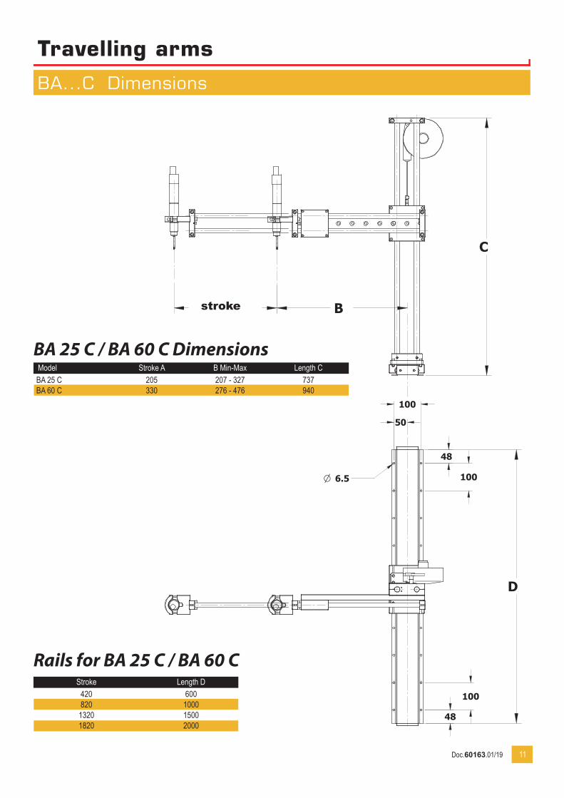
BA 25 C / BA 60 C DimensionsModel Stroke A B Min-Max Length CBA 25 C 205 207 - 327 737BA 60 C 330 276 - 476 940
Rails for BA 25 C / BA 60 CStroke Length D
420 600820 1000
1320 15001820 2000
stroke
Doc.60163.01/19
Articulated reaction arms
BA...R Series
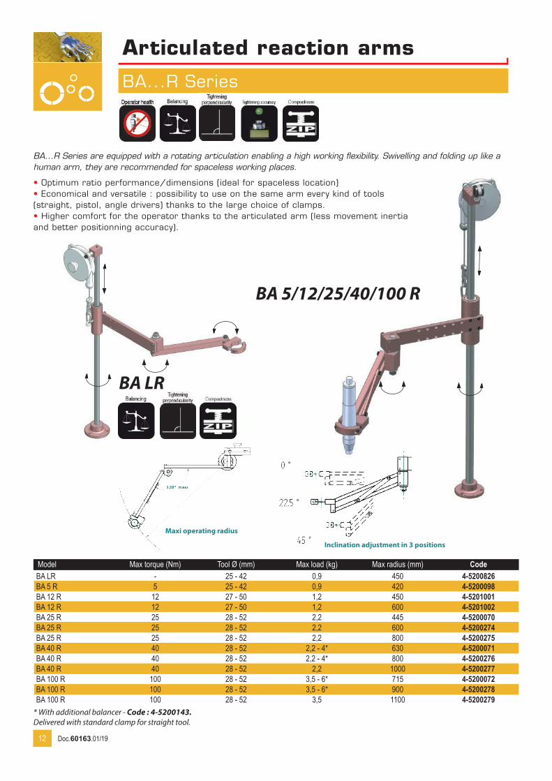
Model Max torque (Nm) Tool Ø (mm) Max load (kg) Max radius (mm) CodeBA LR - 25 - 42 0,9 450 4-5200826BA 5 R 5 25 - 42 0,9 420 4-5200098BA 12 R 12 27 - 50 1,2 450 4-5201001BA 12 R 12 27 - 50 1,2 600 4-5201002BA 25 R 25 28 - 52 2,2 445 4-5200070BA 25 R 25 28 - 52 2,2 600 4-5200274BA 25 R 25 28 - 52 2,2 800 4-5200275BA 40 R 40 28 - 52 2,2 - 4* 630 4-5200071BA 40 R 40 28 - 52 2,2 - 4* 800 4-5200276BA 40 R 40 28 - 52 2,2 1000 4-5200277BA 100 R 100 28 - 52 3,5 - 6* 715 4-5200072BA 100 R 100 28 - 52 3,5 - 6* 900 4-5200278BA 100 R 100 28 - 52 3,5 1100 4-5200279
* With additional balancer - Code : 4-5200143. Delivered with standard clamp for straight tool.
BA...R Series are equipped with a rotating articulation enabling a high working flexibility. Swivelling and folding up like a human arm, they are recommended for spaceless working places.
• Optimum ratio performance/dimensions (ideal for spaceless location)• Economical and versatile : possibility to use on the same arm every kind of tools (straight, pistol, angle drivers) thanks to the large choice of clamps.• Higher comfort for the operator thanks to the articulated arm (less movement inertia and better positionning accuracy).
BA 5/12/25/40/100 R
12
Inclination adjustment in 3 positions
Maxi operating radius
BA LR
Doc.60163.01/19
Articulated reaction arms
BA...R Accessories
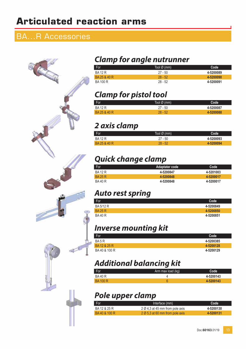
Clamp for angle nutrunnerFor Tool Ø (mm) CodeBA 12 R 27 - 50 4-5200089BA 25 & 40 R 28 - 52 4-5200090BA 100 R 28 - 52 4-5200091
Clamp for pistol toolFor Tool Ø (mm) CodeBA 12 R 27 - 50 4-5200087BA 25 & 40 R 28 - 52 4-5200088
2 axis clampFor Tool Ø (mm) CodeBA 12 R 27 - 50 4-5200093BA 25 & 40 R 28 - 52 4-5200094
Quick change clampFor Adaptater code CodeBA 12 R 4-5200847 4-5201003BA 25 R 4-5200848 4-5200017BA 40 R 4-5200848 4-5200017
Auto rest springFor CodeBA 5/12 R 4-5200849BA 25 R 4-5200850BA 40 R 4-5200851
Inverse mounting kitFor CodeBA 5 R 4-5200385BA 12 & 25 R 4-5200128BA 40 & 100 R 4-5200129
Additional balancing kitFor Arm max load (kg) CodeBA 40 R 4 4-5200143BA 100 R 6 4-5200143
Pole upper clampFor Interface (mm) CodeBA 12 & 25 R 2 Ø 4,3 at 45 mm from pole axis 4-5200130BA 40 & 100 R 2 Ø 5,3 at 60 mm from pole axis 4-5200131
13Doc.60163.01/19
Articulated reaction arms
BA...R Accessories
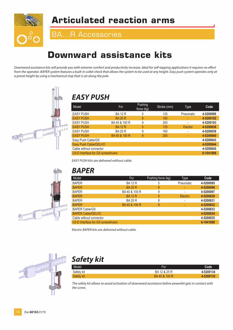
EASY PUSHModel For Pushing
force (kg) Stroke (mm) Type Code
EASY PUSH BA 12 R 5 125 Pneumatic 4-5200099EASY PUSH BA 25 R 9 160 - 4-5200102EASY PUSH BA 40 & 100 R 9 200 - 4-5200103EASY PUSH BA 12 R 5 125 Electric 4-5200838EASY PUSH BA 25 R 9 160 - 4-5200839EASY PUSH BA 40 & 100 R 9 200 - 4-5200840Easy Push Cable/GX 4-5200843Easy Push Cable/DELVO 4-5200844Cable without connector 4-5200845U3-D Interface for GX screwdrivers 6-1041888
BAPERModel For Pushing force (kg) Type CodeBAPER BA 12 R 5 Pneumatic 4-5200095BAPER BA 25 R 8 - 4-5200096BAPER BA 40 & 100 R 8 - 4-5200097BAPER BA 12 R 5 Electric 4-5200830BAPER BA 25 R 8 - 4-5200831BAPER BA 40 & 100 R 8 - 4-5200832BAPER Cable/GX 4-5200833BAPER Cable/DELVO 4-5200834Cable without connector 4-5200835U3-D Interface for GX screwdrivers 6-1041888
Safety kitModel For CodeSafety kit BA 12 & 25 R 4-5200134Safety kit BA 40 & 100 R 4-5200135
14
Downward assistance kitsxxxxDownward assistance kits will provide you with extreme comfort and productivity increase. Ideal for self-tapping applications it requires no effort from the operator. BAPER system features a built-in collet check that allows the system to be used at any height. Easy push system operates only at a preset height by using a mechanical stop that is set along the pole.
The safety kit allows to avoid activation of downward assistance before powerbit gets in contact with the screw.
Electric BAPER kits are delivered without cable.
EASY PUSH kits are delivered without cable.
Doc.60163.01/19
Articulated reaction arms
BA...R high torque
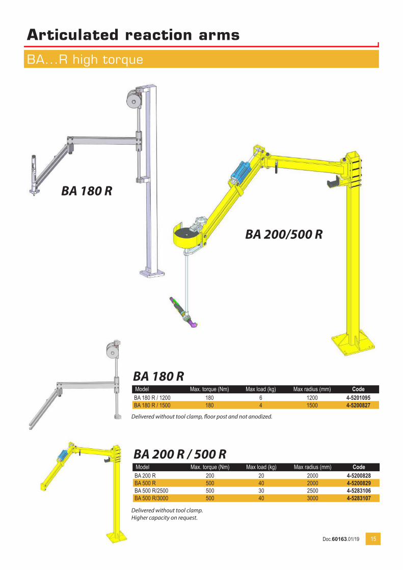
BA 180 RModel Max. torque (Nm) Max load (kg) Max radius (mm) CodeBA 180 R / 1200 180 6 1200 4-5201095BA 180 R / 1500 180 4 1500 4-5200827
BA 200 R / 500 RModel Max. torque (Nm) Max load (kg) Max radius (mm) CodeBA 200 R 200 20 2000 4-5200828BA 500 R 500 40 2000 4-5200829BA 500 R/2500 500 30 2500 4-5283106BA 500 R/3000 500 40 3000 4-5283107
15
BA 200/500 R
BA 180 R
Delivered without tool clamp, floor post and not anodized.
Delivered without tool clamp.Higher capacity on request.
Doc.60163.01/19
Articulated reaction arms
BA...R high torque accessories
16
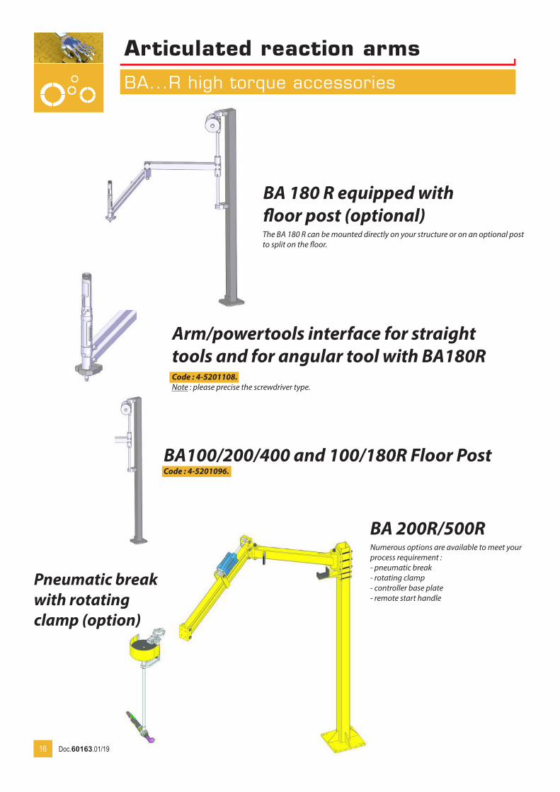
BA 180 R equipped with floor post (optional)
Arm/powertools interface for straight tools and for angular tool with BA180RCode : 4-5201108.Note : please precise the screwdriver type.
BA100/200/400 and 100/180R Floor PostCode : 4-5201096.
Pneumatic break with rotating clamp (option)
BA 200R/500R
The BA 180 R can be mounted directly on your structure or on an optional post to split on the floor.
Numerous options are available to meet your process requirement :- pneumatic break- rotating clamp- controller base plate- remote start handle
Doc.60163.01/19

Articulated reaction arms
BA...R 5 to 100 Dimensions
17
BA...R dimensionsModel A 0°
(mm)A 22,5°
(mm)A 45°(mm)
B
C(mm)
Operating radius at 22,5° (mm)
BA 5 R 259 243 192 132 212 705 420BA 12 R 279 261 209 102 252 808 450BA 12 R / 600 332 310 247 332 357 808 600BA 25 R 296 278 227 95 245 908 460BA 25 R / 600 358 336 271 305 330 908 600BA 25 R / 800 483 452 360 417 442 908 800BA 40 R 414 387,5 310,5 150 350 1008 650BA 40 R / 800 503 470 374 415 415 1008 800BA 40 R / 1000 640 597 471 520 520 1008 1000BA 100 R 462 433 351 205 405 1008 730BA 100 R / 900 564 528 425 470 520 1008 900BA 100 R / 1100 694 648 517 585 635 1008 1100
Stroke : A
at on
Max (mm)Min
Doc.60163.01/19
Articulated reaction arms
BA 180 R Dimensions
18
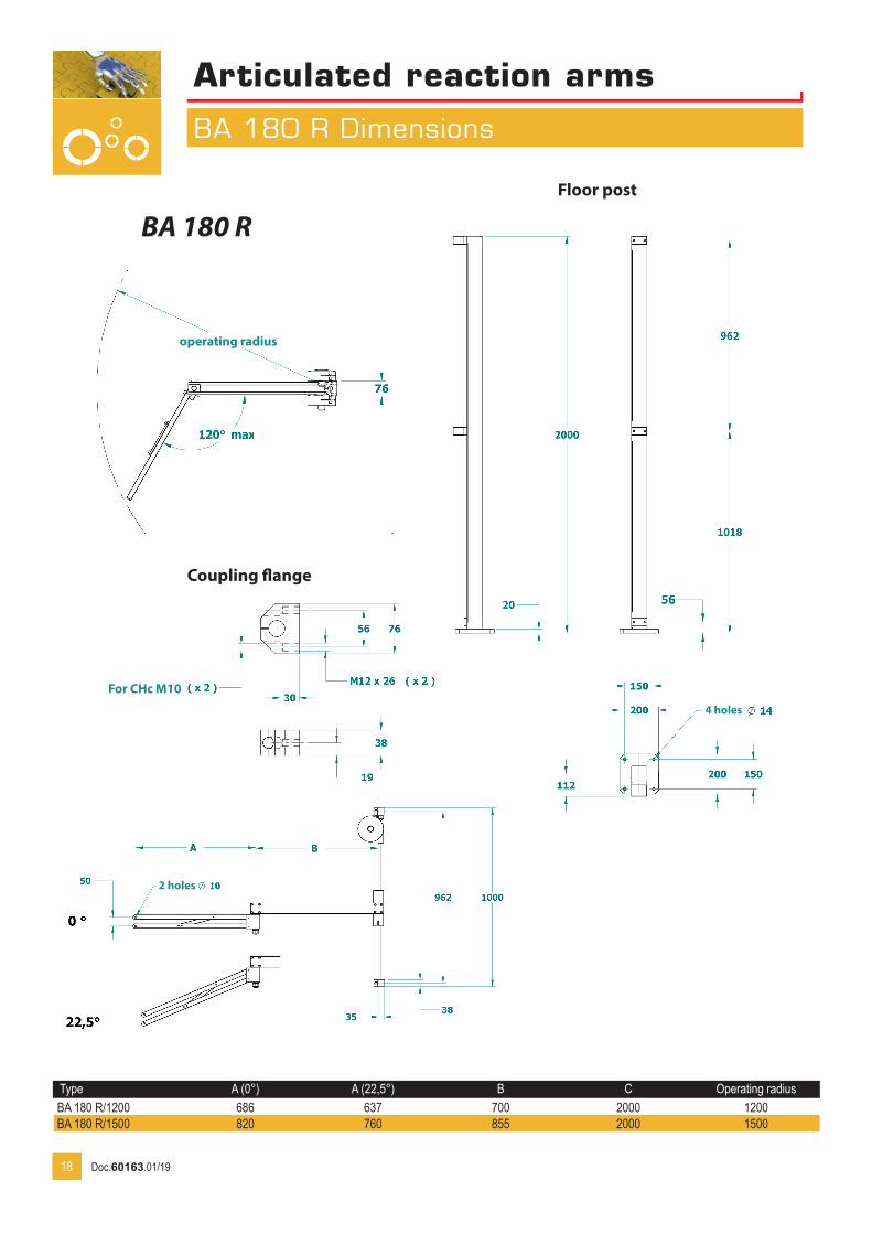
BA 180 R
Type A (0°) A (22,5°) B C Operating radiusBA 180 R/1200 686 637 700 2000 1200BA 180 R/1500 820 760 855 2000 1500
operating radius
For CHc M10
2 holes
4 holes
Coupling flange
Floor post
Doc.60163.01/19
Articulated reaction arms
BA 200 & 500 R Dimensions
19
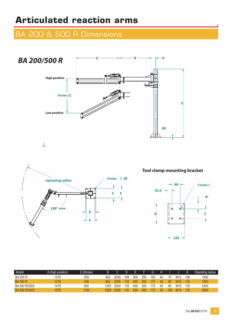
Model A (high position) Z (Stroke) B C D E F G H I J K Operating radiusBA 200 R 1278 559 943 2000 108 300 250 150 40 70 M12 108 1900BA 500 R 1278 559 943 2000 118 400 350 170 45 80 M16 118 1900BA 500 R/2500 1478 650 1293 2000 118 400 350 170 45 80 M16 118 2400BA 500 R/3000 1978 1100 1560 2000 118 500 450 170 45 100 M16 118 2900
BA 200/500 R
operating radius 4 holes
4 holes J
Tool clamp mounting bracket
High position
Low position
Stroke (Z)
Doc.60163.01/19

20
Model Torque Max (Nm) Tool Ø (mm) Vertical Stroke (mm) Maxi load (Kg) Max radius (mm) CodeBA10 G 10 27 - 50 170 1 470 4-5201013BA10 G/600 10 27 - 50 170 1 600 4-5201014BA30 G 30 28 - 52 220 2 670 4-5201015BA30 G/800 30 28 - 52 220 2 800 4-5201016
BA10 G
Inspired from the BA...R Series, the BA...G Series provides you even more flexibility and confort thanks to the air balanced design.
• Softly air balanced !• Quick and quiet !
BA30 G
-Date
-Vérifié par GP
Emision originaleNote de révision
AN° Rév
Tolérances générales: ±0.2 Ra 3.2Casser les angles vifs
Nom pièce
Nom ensemble
Plan N°: 15-14-4073Traitement:
Matière:
Client:Format: A3Ech: 1/1QtéRep Date:17-11-15Dessiné par
Max operating radius
Articulated and air balanced pantograph
BA...G Series
Doc.60163.01/19

-Date
-Vérifié par GP
Emision originaleNote de révision
AN° Rév
Tolérances générales: ±0.2 Ra 3.2Casser les angles vifs
Nom pièce
Nom ensemble
Plan N°: 15-14-4073Traitement:
Matière:
Client:Format: A3Ech: 1/1QtéRep Date:17-11-15Dessiné par
Model A (down position) B mini B maxi C Vertical
Stroke D Dim. E Dim. F Dim. G Max radius (mm)
BA10 G 260 202 252 170 600 8,5 78 65 470BA10 G/600 260 357 407 170 600 8,5 78 65 600BA30 G 391 250 350 218 800 8,5 118 100 670BA30 G/800 391 405 505 218 800 8,5 118 100 800
21
Max operating radius
3 holes Ø E at 120°
on Ø G
Articulated and air balanced pantograph
BA...G Series
Doc.60163.01/19
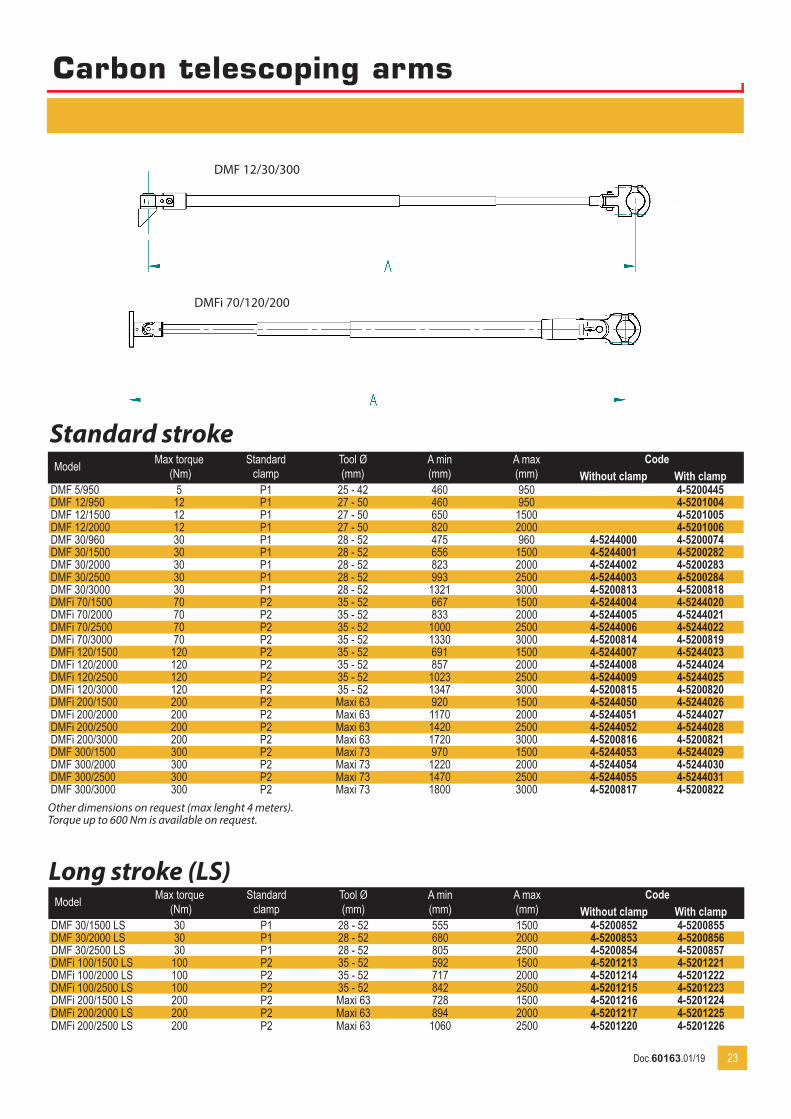
Carbon telescoping arms
DMF/DMFI Series
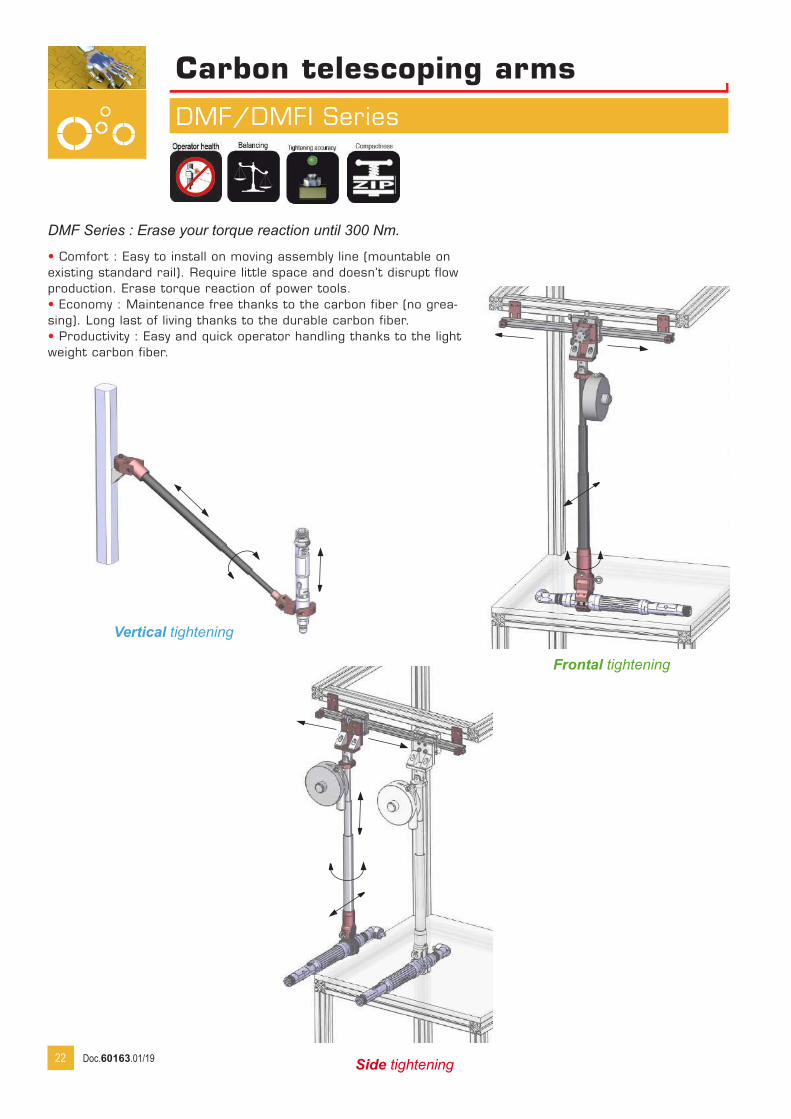
Side tightening
DMF Series : Erase your torque reaction until 300 Nm.
• Comfort : Easy to install on moving assembly line (mountable on existing standard rail). Require little space and doesn’t disrupt flow production. Erase torque reaction of power tools.• Economy : Maintenance free thanks to the carbon fiber (no grea-sing). Long last of living thanks to the durable carbon fiber.• Productivity : Easy and quick operator handling thanks to the light weight carbon fiber.
Vertical tightening
Frontal tightening
22 Doc.60163.01/19
23
Carbon telescoping arms
Model Max torque (Nm)
Standardclamp
Tool Ø(mm)
A min (mm)
A max(mm)
CodeWithout clamp With clamp
DMF 5/950 5 P1 25 - 42 460 950 4-5200445DMF 12/950 12 P1 27 - 50 460 950 4-5201004DMF 12/1500 12 P1 27 - 50 650 1500 4-5201005DMF 12/2000 12 P1 27 - 50 820 2000 4-5201006DMF 30/960 30 P1 28 - 52 475 960 4-5244000 4-5200074DMF 30/1500 30 P1 28 - 52 656 1500 4-5244001 4-5200282DMF 30/2000 30 P1 28 - 52 823 2000 4-5244002 4-5200283DMF 30/2500 30 P1 28 - 52 993 2500 4-5244003 4-5200284DMF 30/3000 30 P1 28 - 52 1321 3000 4-5200813 4-5200818DMFi 70/1500 70 P2 35 - 52 667 1500 4-5244004 4-5244020DMFi 70/2000 70 P2 35 - 52 833 2000 4-5244005 4-5244021DMFi 70/2500 70 P2 35 - 52 1000 2500 4-5244006 4-5244022DMFi 70/3000 70 P2 35 - 52 1330 3000 4-5200814 4-5200819DMFi 120/1500 120 P2 35 - 52 691 1500 4-5244007 4-5244023DMFi 120/2000 120 P2 35 - 52 857 2000 4-5244008 4-5244024DMFi 120/2500 120 P2 35 - 52 1023 2500 4-5244009 4-5244025DMFi 120/3000 120 P2 35 - 52 1347 3000 4-5200815 4-5200820DMFi 200/1500 200 P2 Maxi 63 920 1500 4-5244050 4-5244026DMFi 200/2000 200 P2 Maxi 63 1170 2000 4-5244051 4-5244027DMFi 200/2500 200 P2 Maxi 63 1420 2500 4-5244052 4-5244028DMFi 200/3000 200 P2 Maxi 63 1720 3000 4-5200816 4-5200821DMF 300/1500 300 P2 Maxi 73 970 1500 4-5244053 4-5244029DMF 300/2000 300 P2 Maxi 73 1220 2000 4-5244054 4-5244030DMF 300/2500 300 P2 Maxi 73 1470 2500 4-5244055 4-5244031DMF 300/3000 300 P2 Maxi 73 1800 3000 4-5200817 4-5200822
DMF 12/30/300
DMFi 70/120/200
Other dimensions on request (max lenght 4 meters).Torque up to 600 Nm is available on request.
Standard stroke
Model Max torque (Nm)
Standardclamp
Tool Ø(mm)
A min (mm)
A max(mm)
CodeWithout clamp With clamp
DMF 30/1500 LS 30 P1 28 - 52 555 1500 4-5200852 4-5200855DMF 30/2000 LS 30 P1 28 - 52 680 2000 4-5200853 4-5200856DMF 30/2500 LS 30 P1 28 - 52 805 2500 4-5200854 4-5200857DMFi 100/1500 LS 100 P2 35 - 52 592 1500 4-5201213 4-5201221DMFi 100/2000 LS 100 P2 35 - 52 717 2000 4-5201214 4-5201222DMFi 100/2500 LS 100 P2 35 - 52 842 2500 4-5201215 4-5201223DMFi 200/1500 LS 200 P2 Maxi 63 728 1500 4-5201216 4-5201224DMFi 200/2000 LS 200 P2 Maxi 63 894 2000 4-5201217 4-5201225DMFi 200/2500 LS 200 P2 Maxi 63 1060 2500 4-5201220 4-5201226
Long stroke (LS)
Doc.60163.01/19
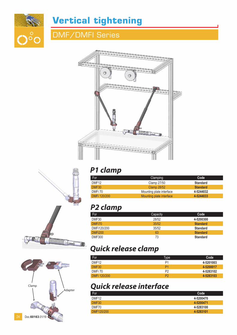
Vertical tightening
DMF/DMFI Series
P1 clamp
Quick release interfaceFor CodeDMF12 4-5200470DMF30 4-5200471DMF70 4-5283100DMF120/200 4-5283101
For Clamping CodeDMF12 Clamp 27/50 StandardDMF30 Clamp 28/52 StandardDMFi 70 Mounting plate interface 4-5244032DMFi 120/200 Mounting plate interface 4-5244033
24
ClampAdapter
P2 clampFor Capacity CodeDMF30 28/52 4-5200300DMFi70 35/52 StandardDMFi120/200 35/52 StandardDMFi200 63 StandardDMF300 73 Standard
Quick release clampFor Type CodeDMF12 P1 4-5201003DMF30 P1 4-5200017DMFi 70 P2 4-5283102DMFi 120/200 P2 4-5283103
Doc.60163.01/19
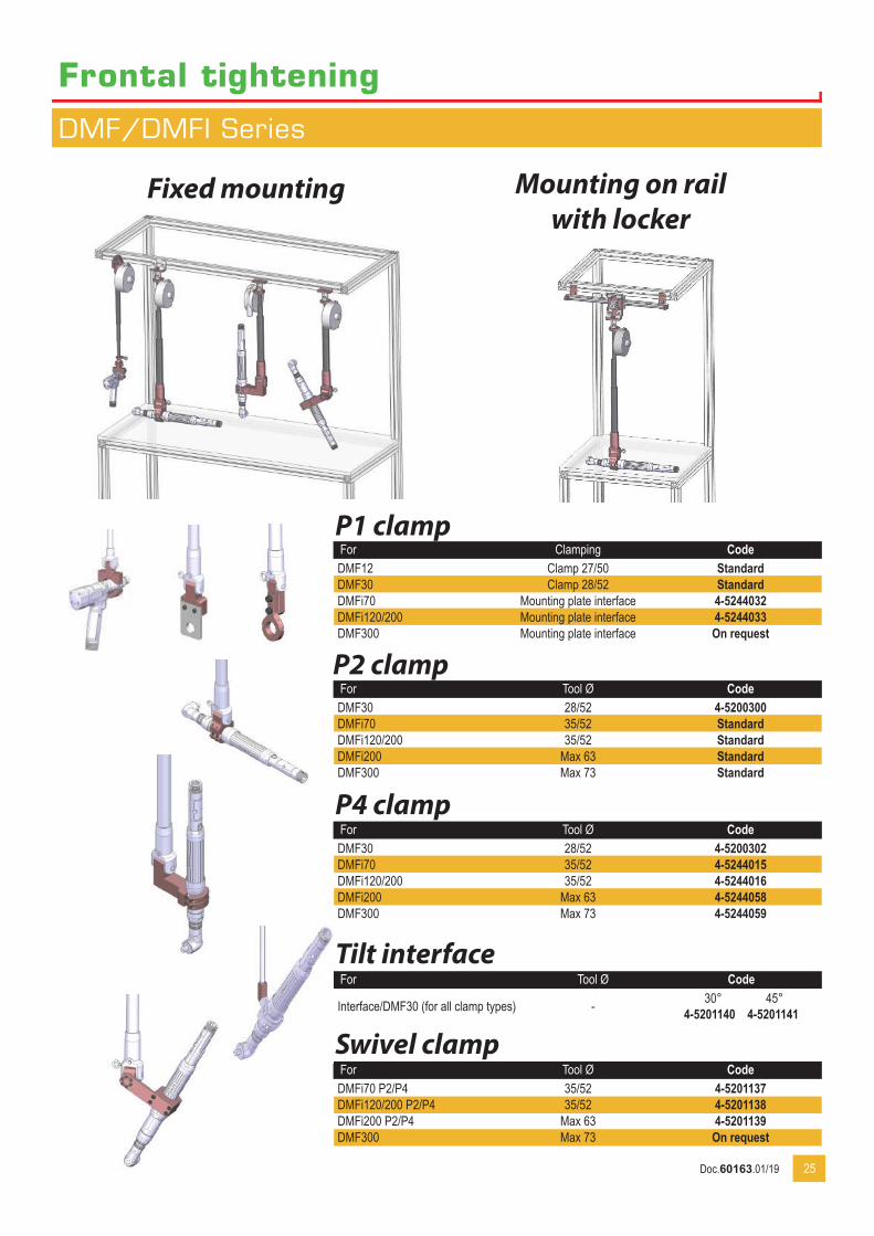
Frontal tightening
DMF/DMFI Series
P1 clamp
P2 clamp
P4 clamp
Swivel clamp
Fixed mounting Mounting on rail with locker
For Clamping CodeDMF12 Clamp 27/50 StandardDMF30 Clamp 28/52 StandardDMFi70 Mounting plate interface 4-5244032DMFi120/200 Mounting plate interface 4-5244033DMF300 Mounting plate interface On request
For Tool Ø CodeDMF30 28/52 4-5200300DMFi70 35/52 StandardDMFi120/200 35/52 StandardDMFi200 Max 63 StandardDMF300 Max 73 Standard
For Tool Ø CodeDMF30 28/52 4-5200302DMFi70 35/52 4-5244015DMFi120/200 35/52 4-5244016DMFi200 Max 63 4-5244058DMF300 Max 73 4-5244059
For Tool Ø CodeDMFi70 P2/P4 35/52 4-5201137DMFi120/200 P2/P4 35/52 4-5201138DMFi200 P2/P4 Max 63 4-5201139DMF300 Max 73 On request
25
Tilt interfaceFor Tool Ø Code
Interface/DMF30 (for all clamp types) - 4-5201140 4-520114145°30°
Doc.60163.01/19
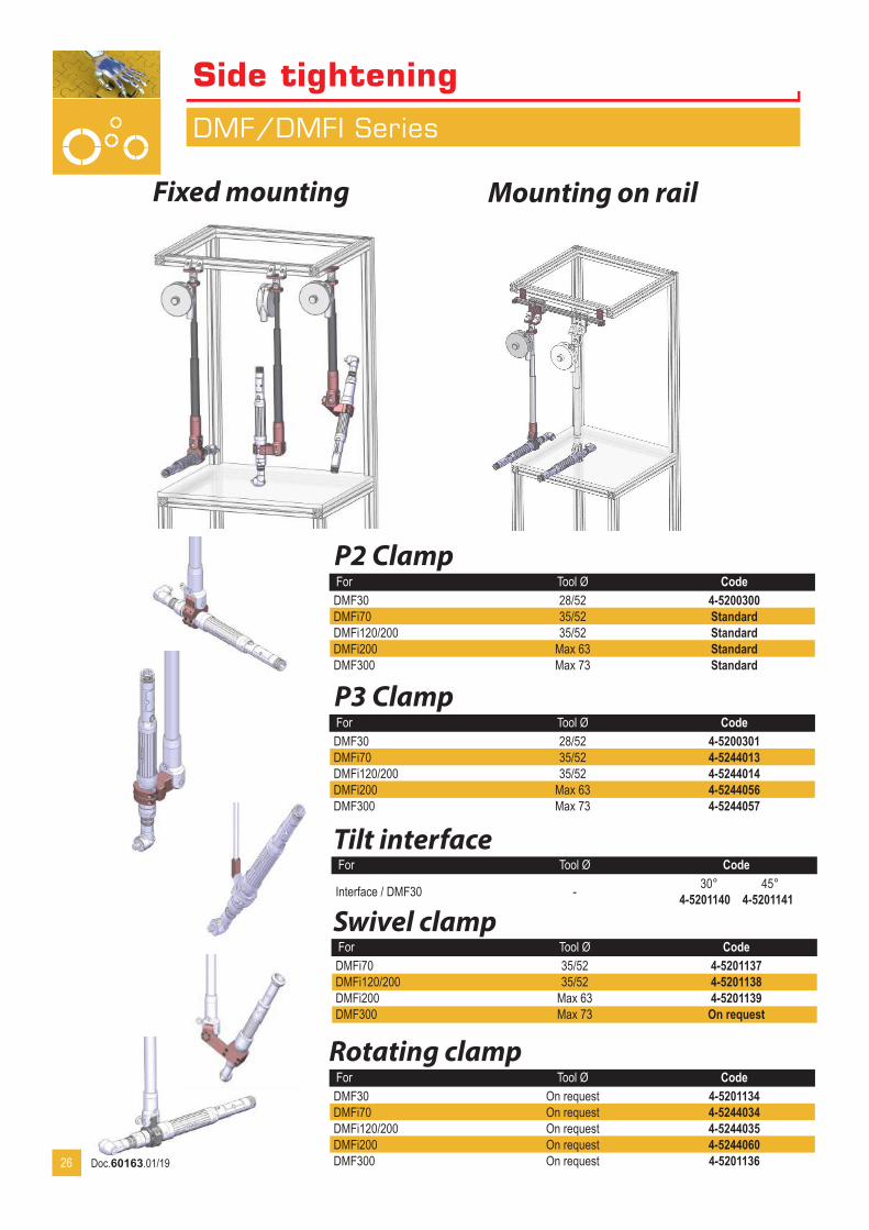
Side tightening
DMF/DMFI Series
Fixed mounting Mounting on rail
P2 ClampFor Tool Ø CodeDMF30 28/52 4-5200300DMFi70 35/52 StandardDMFi120/200 35/52 StandardDMFi200 Max 63 StandardDMF300 Max 73 Standard
P3 ClampFor Tool Ø CodeDMF30 28/52 4-5200301DMFi70 35/52 4-5244013DMFi120/200 35/52 4-5244014DMFi200 Max 63 4-5244056DMF300 Max 73 4-5244057
Rotating clampFor Tool Ø CodeDMF30 On request 4-5201134DMFi70 On request 4-5244034DMFi120/200 On request 4-5244035DMFi200 On request 4-5244060DMF300 On request 4-520113626
Swivel clampFor Tool Ø CodeDMFi70 35/52 4-5201137DMFi120/200 35/52 4-5201138DMFi200 Max 63 4-5201139DMF300 Max 73 On request
Tilt interfaceFor Tool Ø Code
Interface / DMF30 - 4-5201140 4-520114145°30°
Doc.60163.01/19

DMF/DMFi
Mounting on rail
Rails
Rail interface
Pneumatic locker
Absorbing stop
Adjustable stop
Additional flange
Length Stroke Number of flanges Code600 450 2 4-5200132800 650 2 4-52001601000 850 2 4-52001611200 1050 3 4-52001621500 1350 3 4-52001632000 1850 4 4-5200164
Allows installation of DMF on rail.For CodeDMF12/30 4-5200341DMFi70/120/200 4-5200708DMF300 4-5200342
NOTE : delivered without safety hook (Code 4-5200309)
For Type CodeDMF12/30 Pneumatic 4-5200442DMF12/30 Electric 4-5200869DMFi70/120 Pneumatic 4-5200706DMFi70/120 Electric 4-5200707DMFi200 Electric 4-5201150DMF300 Electric 4-5201142
Recommended in case of repeatable side shocks.Code 4-5201121 Set of 2
To limit the slide of the arm on the rail.Code 4-5200167
To reintorce the rail installation for high torque applications. Code 4-5200873
27
The powertool has to be equipped with a motor run signal.
Doc.60163.01/19
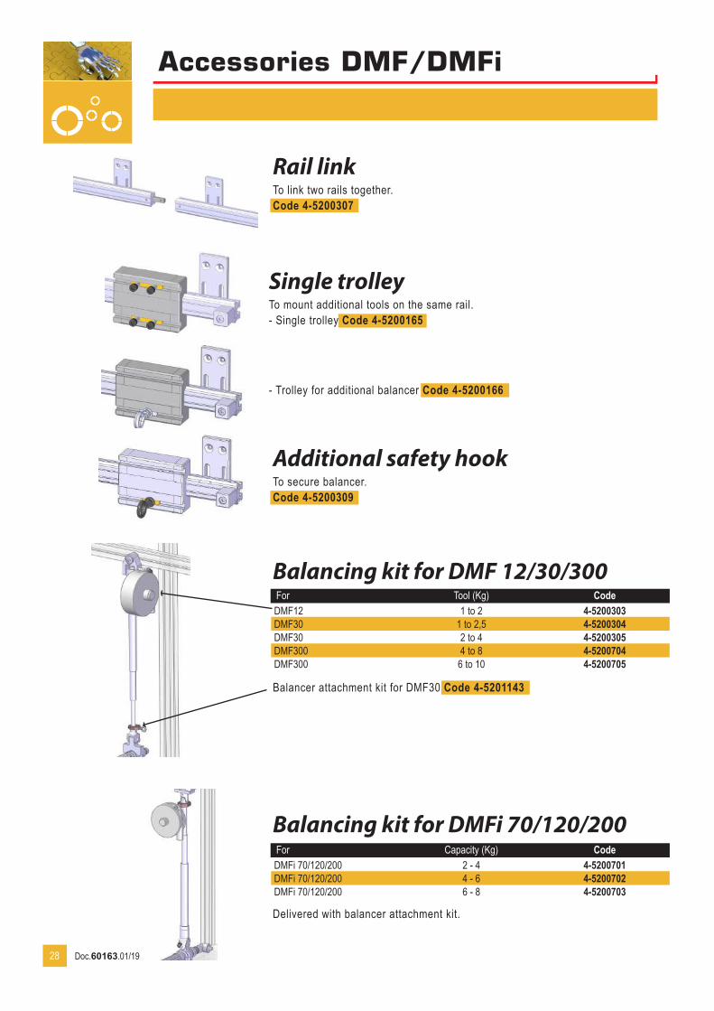
Accessories DMF/DMFi
Rail linkTo link two rails together. Code 4-5200307
Single trolleyTo mount additional tools on the same rail. - Single trolley Code 4-5200165
Additional safety hookTo secure balancer. Code 4-5200309
Balancing kit for DMF 12/30/300
Balancing kit for DMFi 70/120/200
For Tool (Kg) CodeDMF12 1 to 2 4-5200303DMF30 1 to 2,5 4-5200304DMF30 2 to 4 4-5200305DMF300 4 to 8 4-5200704DMF300 6 to 10 4-5200705
Balancer attachment kit for DMF30 Code 4-5201143
For Capacity (Kg) CodeDMFi 70/120/200 2 - 4 4-5200701DMFi 70/120/200 4 - 6 4-5200702DMFi 70/120/200 6 - 8 4-5200703
Delivered with balancer attachment kit.
28
- Trolley for additional balancer Code 4-5200166
Doc.60163.01/19
xxxxx
29
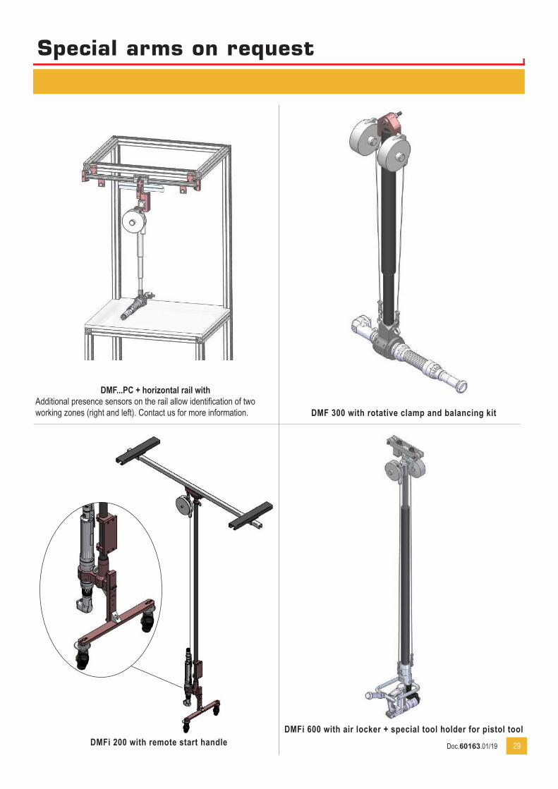
Special arms on request
DMF 300 with rotative clamp and balancing kit
DMFi 200 with remote start handleDMFi 600 with air locker + special tool holder for pistol tool
DMF...PC + horizontal rail withAdditional presence sensors on the rail allow identification of two working zones (right and left). Contact us for more information.
Doc.60163.01/19

Model Max torque (Nm) Clamping Ø (mm) Vertical stroke (mm) Working radius (mm) Load (kg) CodeSLIDER 08 8 1/4’’ G 450 100 1,2 4-5200077SLIDER 08 COMPACT 8 1/4’’ G 250 150 1,2 4-5200179SLIDER 20 20 1/4’’ G 450 100 2,2 4-5200457SLIDER 50 COMPACT 450 50 32 - 52 450 3 4-5283110SLIDER 50 COMPACT 650 50 32 - 52 650 3 4-5283111SLIDER 50 COMPACT 850 50 32 - 52 850 3 4-5283112SLIDER 150 COMPACT 600 150 Max 63 600 5 4-5283113SLIDER 150 COMPACT 800 150 Max 63 800 5 4-5283114SLIDER 150 COMPACT 1000 150 Max 63 1000 5 4-5283115SLIDER 300 COMPACT 300 On request On request On request On request On request
SLIDER 8compact
SLIDER 8/20 SLIDER 300 COMPACT
SLIDER 50/150 COMPACTTightening vertical/horizontal
Suspended arms
Slider
30
SLIDER Series : Erase your torque reaction until 300 Nm.
• IMPROVE YOUR COMFORT AND PRODUCTIVITYEasy to install and smart-sized the SLIDER arms improve the comfort of the operator and the productivity clearing the work area.• IMPROVE YOUR ERGONOMYMounted with horizontal stroke the SLIDER becomes the ideal ergonomical solution on conveyor line.
Doc.60163.01/19
Suspended arms
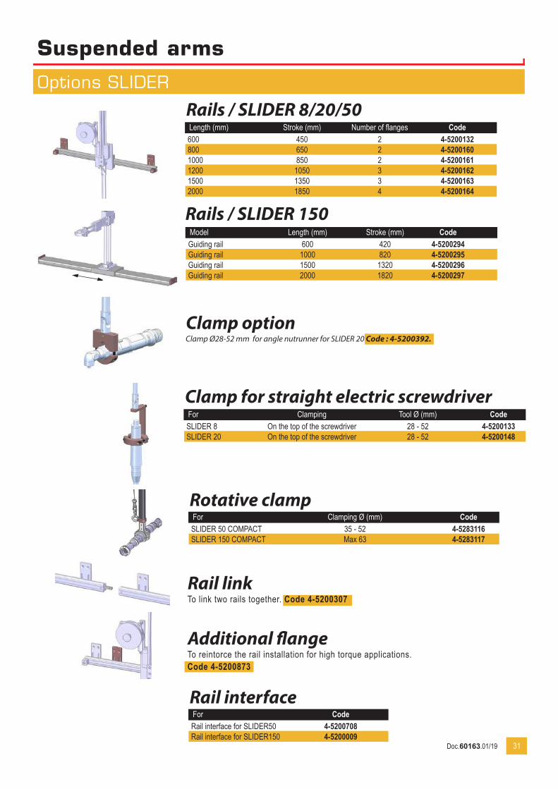
Options SLIDER
Clamp optionClamp Ø28-52 mm for angle nutrunner for SLIDER 20 Code : 4-5200392.
Clamp for straight electric screwdriverFor Clamping Tool Ø (mm) CodeSLIDER 8 On the top of the screwdriver 28 - 52 4-5200133SLIDER 20 On the top of the screwdriver 28 - 52 4-5200148
Rails / SLIDER 8/20/50Length (mm) Stroke (mm) Number of flanges Code600 450 2 4-5200132800 650 2 4-52001601000 850 2 4-52001611200 1050 3 4-52001621500 1350 3 4-52001632000 1850 4 4-5200164
Rail linkTo link two rails together. Code 4-5200307
Additional flangeTo reintorce the rail installation for high torque applications. Code 4-5200873
31
Rotative clampFor Clamping Ø (mm) CodeSLIDER 50 COMPACT 35 - 52 4-5283116SLIDER 150 COMPACT Max 63 4-5283117
Rails / SLIDER 150Model Length (mm) Stroke (mm) CodeGuiding rail 600 420 4-5200294Guiding rail 1000 820 4-5200295Guiding rail 1500 1320 4-5200296Guiding rail 2000 1820 4-5200297
Rail interfaceFor CodeRail interface for SLIDER50 4-5200708Rail interface for SLIDER150 4-5200009
Doc.60163.01/19
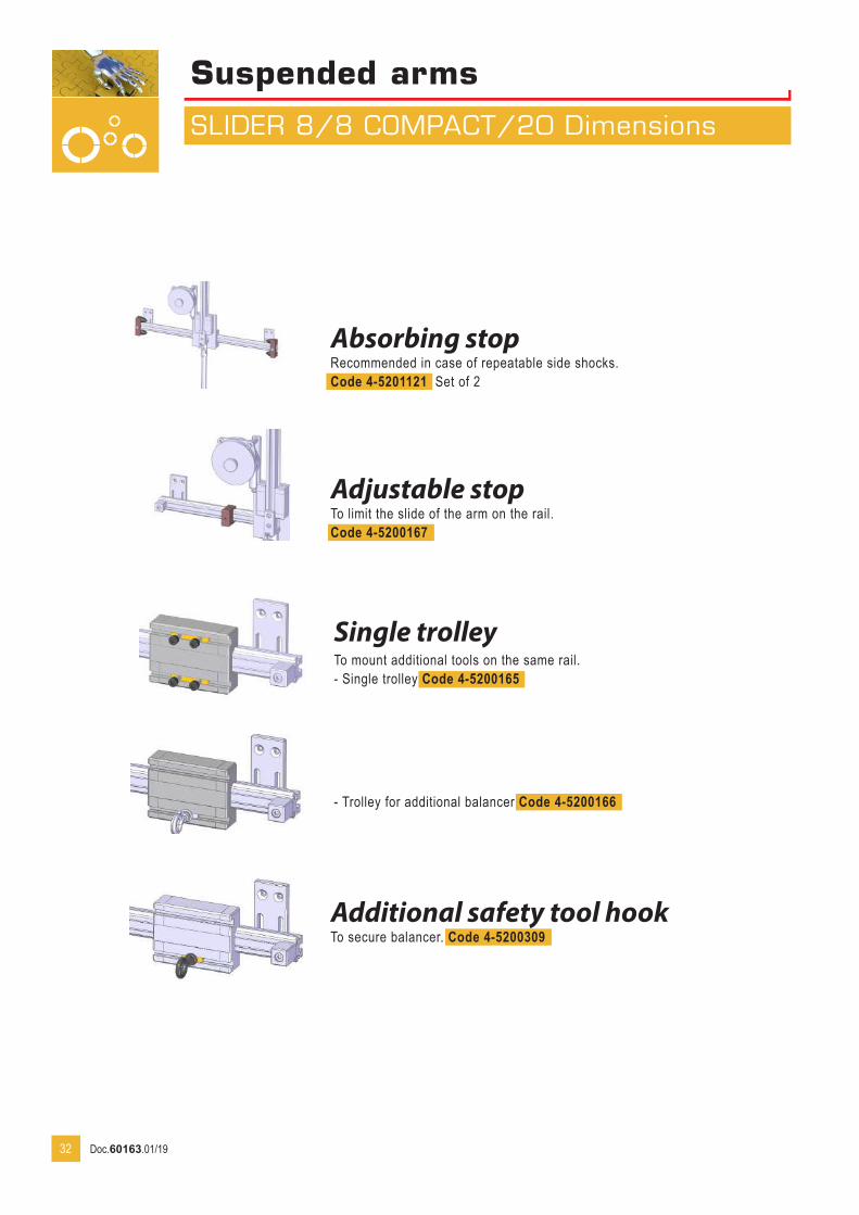
Suspended arms
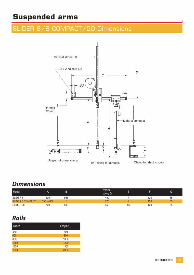
SLIDER 8/8 COMPACT/20 Dimensions
32
Absorbing stopRecommended in case of repeatable side shocks.Code 4-5201121 Set of 2
Adjustable stopTo limit the slide of the arm on the rail.Code 4-5200167
Additional safety tool hookTo secure balancer. Code 4-5200309
Single trolleyTo mount additional tools on the same rail. - Single trolley Code 4-5200165
- Trolley for additional balancer Code 4-5200166
Doc.60163.01/19
Suspended arms
SLIDER 8/8 COMPACT/20 Dimensions
DimensionsModel A B Vertical
stroke D E F G
SLIDER 8 500 565 450 / 120 35SLIDER 8 COMPACT 550 to 600 / 270 / 120 35SLIDER 20 500 599 450 56 120 35
Rails
33
Stroke Length : C
450 600650 800850 10001050 12001350 15001850 2000
Angle nutrunner clampClamp for electric tools1/4’’ sitting for air tools
Vertical stroke : D
Slider 8 compact
54 max27 min
2 x 2 holes Ø 6.2
Doc.60163.01/19

Suspended arms
SLIDER BA / SLIDER BA...R Series
SLIDER BA 100 R
SLIDER BA 12/25/40 R
Model Max torque (Nm)
Tool Ø (mm)
Vertical stroke(mm)
Stroke(mm)
Operating range (mm) Load (kg) Code
SLIDER BA 12 12 27/50 420 225 1,2 4-5201007SLIDER BA 25 25 28/52 420 250 2,2 4-5200726SLIDER BA 40 40 28/52 420 295 3 4-5201119SLIDER BA 100 100 28/52 420 330 5 4-5201120SLIDER BA 12 R 12 27/50 420 450 1,2 4-5201008SLIDER BA 25 R 25 28/52 420 460 2,2 4-5200872SLIDER BA 25 R/600 25 28/52 420 600 2,2 4-5201114SLIDER BA 40 R 40 28/52 420 650 3 4-5201115SLIDER BA 40 R/800 40 28/52 420 800 3 4-5201116SLIDER BA 100 R 100 28/52 420 730 5 4-5201117SLIDER BA 100 R/900 100 28/52 420 900 5 4-5201118
34
Inclination adjustment in 3 positions
Maxi operating radius
SLIDER BA 12/25/40
Mounted on the top, the working area remains free. The SLIDER Series can be installed on rail. Then a pneumatic locker is necessary to counter react.
Doc.60163.01/19

Suspended arms
SLIDER BA / BA...R Dimensions
Model A B mini B maxi Operating range at 120° C D
SLIDER BA 12 R 261 102 252 474 370 440SLIDER BA 25 R 278 95 245 485 394 425SLIDER BA 25 R/600 336 305 330 607 417 425SLIDER BA 40 R 387,5 150 350 667 482 419SLIDER BA 40 R/800 470 415 415 800 496 419SLIDER BA 100 R 433 205 405 730 597 358SLIDER BA 100 R/900 528 470 520 900 634 358
35
SLIDER BA100
DETAILS FIXATION BRAS SLIDER BA...
SLIDER BA12 / 25 / 40
Model Stroke A B mini B maxi C DSLIDER BA 12 225 186 336 246 436SLIDER BA 25 250 221 396 250 436SLIDER BA 40 295 260 460 314 419SLIDER BA 100 330 315 515 395 358
SLIDER BA100
DETAILS FIXATION BRAS SLIDER BA...
SLIDER BA12 / 25 / 40
SLIDER BA...R
SLIDER BA...
BA...R
Vertical stroke : 420
Vertical stroke : 420 mm
Stroke A
4 holes8 holes
Mounting dimensions SLIDER BA... BA...R
Doc.60163.01/19
36
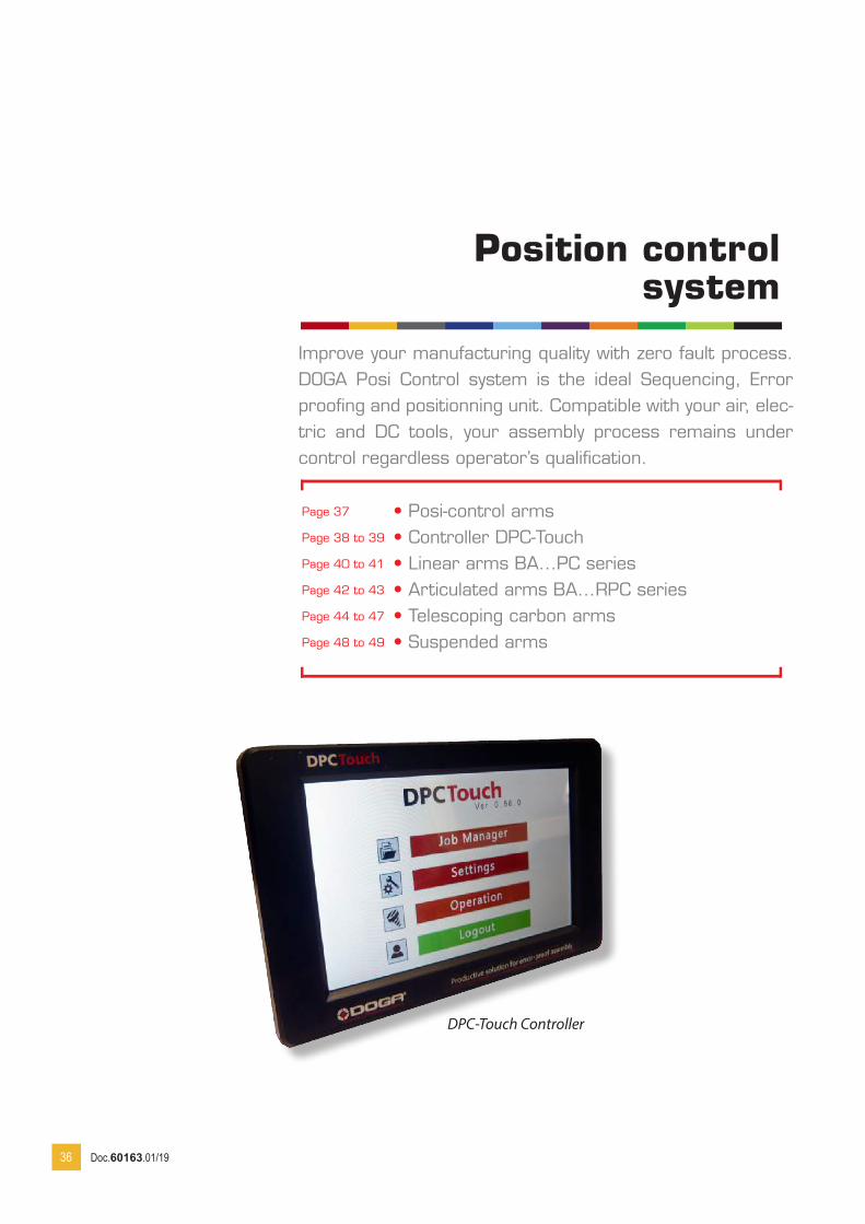
• Posi-control arms• Controller DPC-Touch• Linear arms BA...PC series• Articulated arms BA...RPC series• Telescoping carbon arms• Suspended arms
Page 37
Page 38 to 39
Page 40 to 41
Page 42 to 43
Page 44 to 47
Page 48 to 49
Position control system
Improve your manufacturing quality with zero fault process. DOGA Posi Control system is the ideal Sequencing, Error proofing and positionning unit. Compatible with your air, elec-tric and DC tools, your assembly process remains under control regardless operator’s qualification.
DPC-Touch Controller
Doc.60163.01/19
37
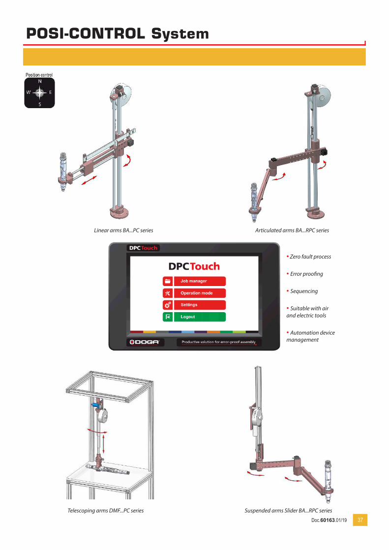
POSI-CONTROL System
Articulated arms BA...RPC seriesLinear arms BA...PC series
Telescoping arms DMF...PC series Suspended arms Slider BA...RPC series
• Zero fault process
• Error proofing
• Sequencing
• Suitable with air and electric tools
• Automation device management
Doc.60163.01/19
POSI-CONTROL System
38
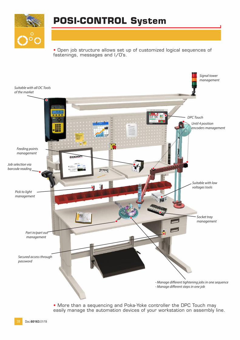
• Open job structure allows set up of customized logical sequences of fastenings, messages and I/O’s.
• More than a sequencing and Poka-Yoke controller the DPC Touch may easily manage the automation devices of your workstation on assembly line.
Socket tray management
Until 4 position encoders management
Signal tower management
Suitable with all DC Tools of the market
- Manage different tightening jobs in one sequence- Manage different steps in one job
Pick to light management
Part in/part out management
DPC Touch
Feeding points management
Suitable with low voltages tools
Secured access through password
Job selection via barcode reading
Doc.60163.01/19
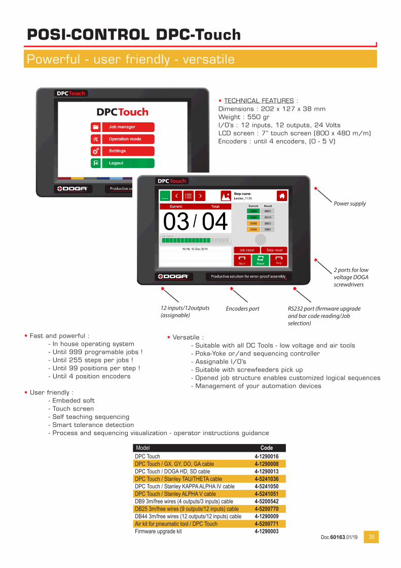
POSI-CONTROL DPC-Touch
Powerful - user friendly - versatile
39
• Fast and powerful : - In house operating system - Until 999 programable jobs ! - Until 255 steps per jobs ! - Until 99 positions per step ! - Until 4 position encoders
• User friendly : - Embeded soft - Touch screen - Self teaching sequencing - Smart tolerance detection - Process and sequencing visualization - operator instructions guidance
• TECHNICAL FEATURES :Dimensions : 202 x 127 x 38 mmWeight : 550 grI/O’s : 12 inputs, 12 outputs, 24 VoltsLCD screen : 7’’ touch screen (800 x 480 m/m)Encoders : until 4 encoders, (0 - 5 V)
RS232 port (firmware upgrade and bar code reading/Job selection)
Encoders port12 inputs/12outputs(assignable)
Power supply
2 ports for low voltage DOGA screwdrivers
• Versatile : - Suitable with all DC Tools - low voltage and air tools - Poka-Yoke or/and sequencing controller - Assignable I/O’s - Suitable with screwfeeders pick up - Opened job structure enables customized logical sequences - Management of your automation devices
Model CodeDPC Touch 4-1290016DPC Touch / GX, GY, DO, GA cable 4-1290008DPC Touch / DOGA HD, SD cable 4-1290013DPC Touch / Stanley TAU/THETA cable 4-5241036DPC Touch / Stanley KAPPA ALPHA IV cable 4-5241050DPC Touch / Stanley ALPHA V cable 4-5241051DB9 3m/free wires (4 outputs/3 inputs) cable 4-5200542DB25 3m/free wires (9 outputs/12 inputs) cable 4-5200770DB44 3m/free wires (12 outputs/12 inputs) cable 4-1290009Air kit for pneumatic tool / DPC Touch 4-5200771Firmware upgrade kit 4-1290003
Doc.60163.01/19
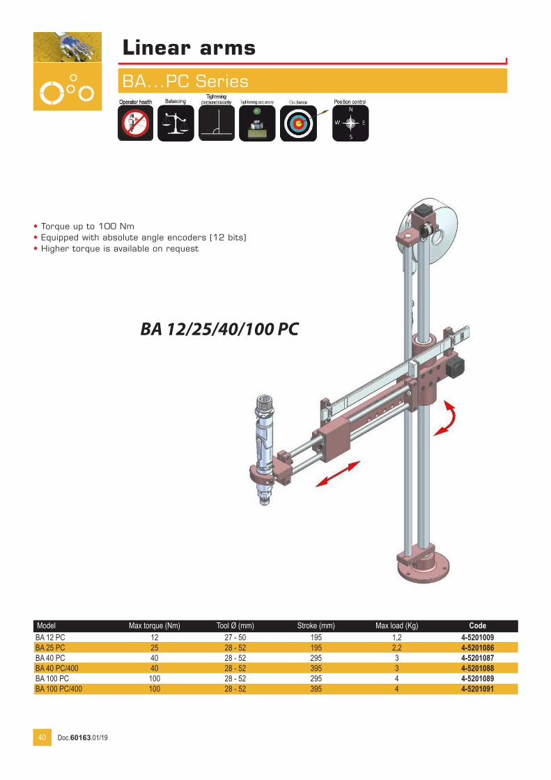
Linear armsBA
BA...PC Series
BA 12/25/40/100 PC
Model Max torque (Nm) Tool Ø (mm) Stroke (mm) Max load (Kg) CodeBA 12 PC 12 27 - 50 195 1,2 4-5201009BA 25 PC 25 28 - 52 195 2,2 4-5201086BA 40 PC 40 28 - 52 295 3 4-5201087BA 40 PC/400 40 28 - 52 395 3 4-5201088BA 100 PC 100 28 - 52 295 4 4-5201089BA 100 PC/400 100 28 - 52 395 4 4-5201091
40
• Torque up to 100 Nm• Equipped with absolute angle encoders (12 bits)• Higher torque is available on request
Doc.60163.01/19
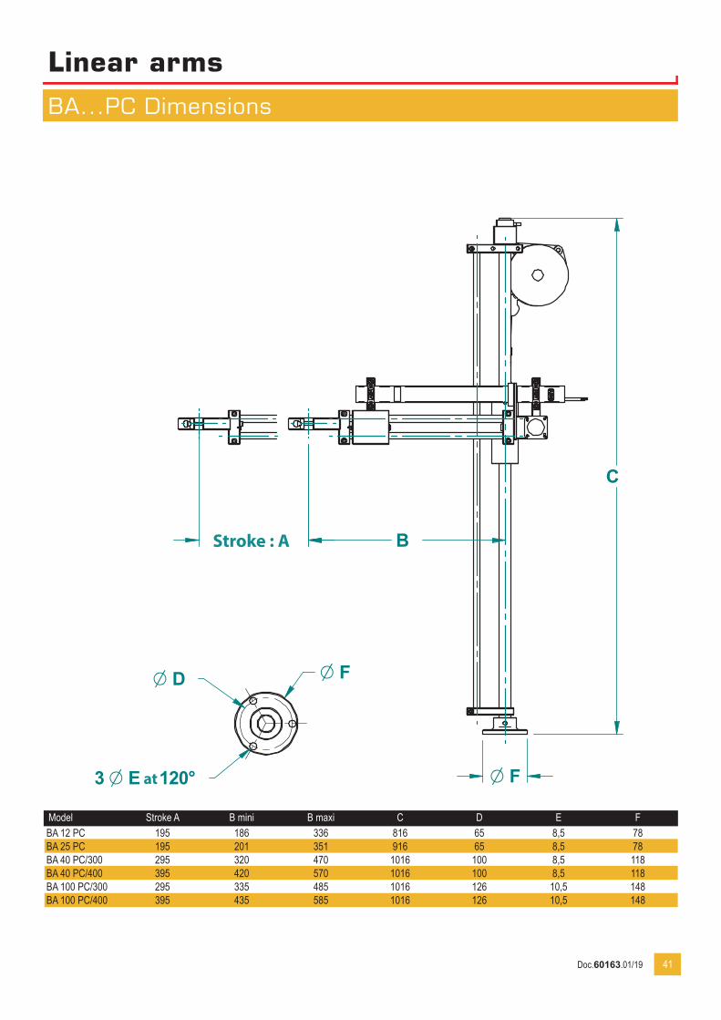
Linear armsBA
BA...PC Dimensions
Dessiné par Date:18-04-13Rep Qté Ech: 1/1 Format: A4 Client:
Matière:
Traitement:
Plan N°:12-50-3809
Nom ensemble
Nom pièce
Tolérances générales: ±0.2 Ra 3.2Casser les angles vifs
N° Rév
ANote de révision
Emission originaleVérifié par GP
-Date
-
C
B
F3 E à 120°
D F
Course : A
Model Stroke A B mini B maxi C D E FBA 12 PC 195 186 336 816 65 8,5 78BA 25 PC 195 201 351 916 65 8,5 78BA 40 PC/300 295 320 470 1016 100 8,5 118BA 40 PC/400 395 420 570 1016 100 8,5 118BA 100 PC/300 295 335 485 1016 126 10,5 148BA 100 PC/400 395 435 585 1016 126 10,5 148
41
Stroke : A
at
Doc.60163.01/19
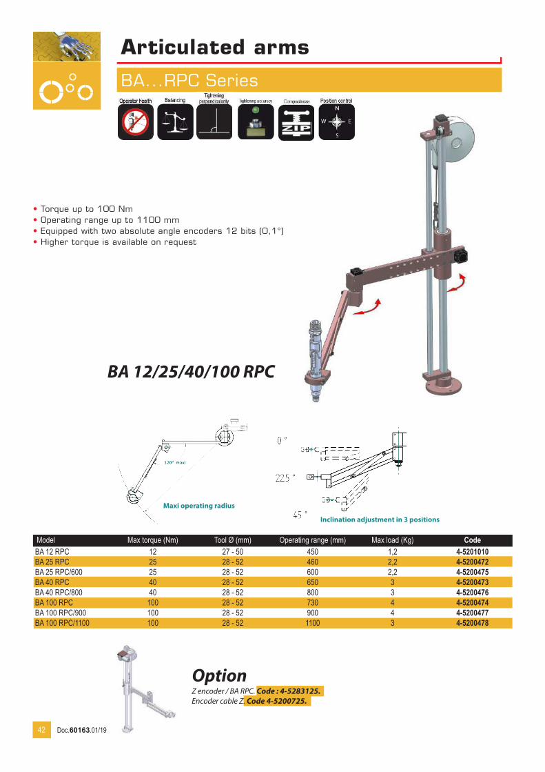
Articulated armsA
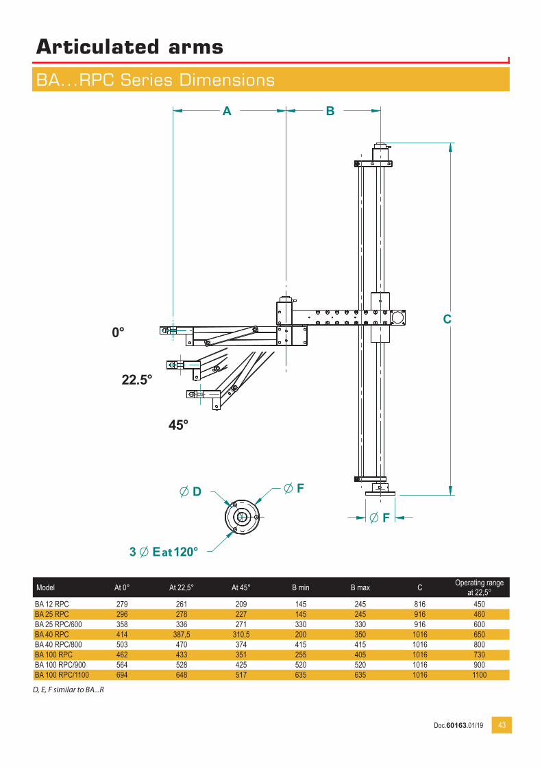
BA...RPC Series
BA 12/25/40/100 RPC
Model Max torque (Nm) Tool Ø (mm) Operating range (mm) Max load (Kg) CodeBA 12 RPC 12 27 - 50 450 1,2 4-5201010BA 25 RPC 25 28 - 52 460 2,2 4-5200472BA 25 RPC/600 25 28 - 52 600 2,2 4-5200475BA 40 RPC 40 28 - 52 650 3 4-5200473BA 40 RPC/800 40 28 - 52 800 3 4-5200476BA 100 RPC 100 28 - 52 730 4 4-5200474BA 100 RPC/900 100 28 - 52 900 4 4-5200477BA 100 RPC/1100 100 28 - 52 1100 3 4-5200478
42
• Torque up to 100 Nm• Operating range up to 1100 mm• Equipped with two absolute angle encoders 12 bits (0,1°)• Higher torque is available on request
Inclination adjustment in 3 positions
Maxi operating radius
OptionZ encoder / BA RPC. Code : 4-5283125.Encoder cable Z. Code 4-5200725.
Doc.60163.01/19
Articulated armsA
BA...RPC Series Dimensions
Dessiné par Date:17-04-13Rep Qté Ech: 1/1 Format: A4 Client:
Matière:
Traitement:
Plan N°:08-52-3387
Nom ensemble
Nom pièce
Tolérances générales: ±0.2 Ra 3.2Casser les angles vifs
N° Rév
ANote de révision
Emission originaleVérifié par GP
-Date
-
C
BA
F
3 E à 120°
D F
0°
22.5°
45°
Model At 0° At 22,5° At 45° B min B max C Operating range at 22,5°
BA 12 RPC 279 261 209 145 245 816 450BA 25 RPC 296 278 227 145 245 916 460BA 25 RPC/600 358 336 271 330 330 916 600BA 40 RPC 414 387,5 310,5 200 350 1016 650BA 40 RPC/800 503 470 374 415 415 1016 800BA 100 RPC 462 433 351 255 405 1016 730BA 100 RPC/900 564 528 425 520 520 1016 900BA 100 RPC/1100 694 648 517 635 635 1016 1100
D, E, F similar to BA...R
43
at
Doc.60163.01/19
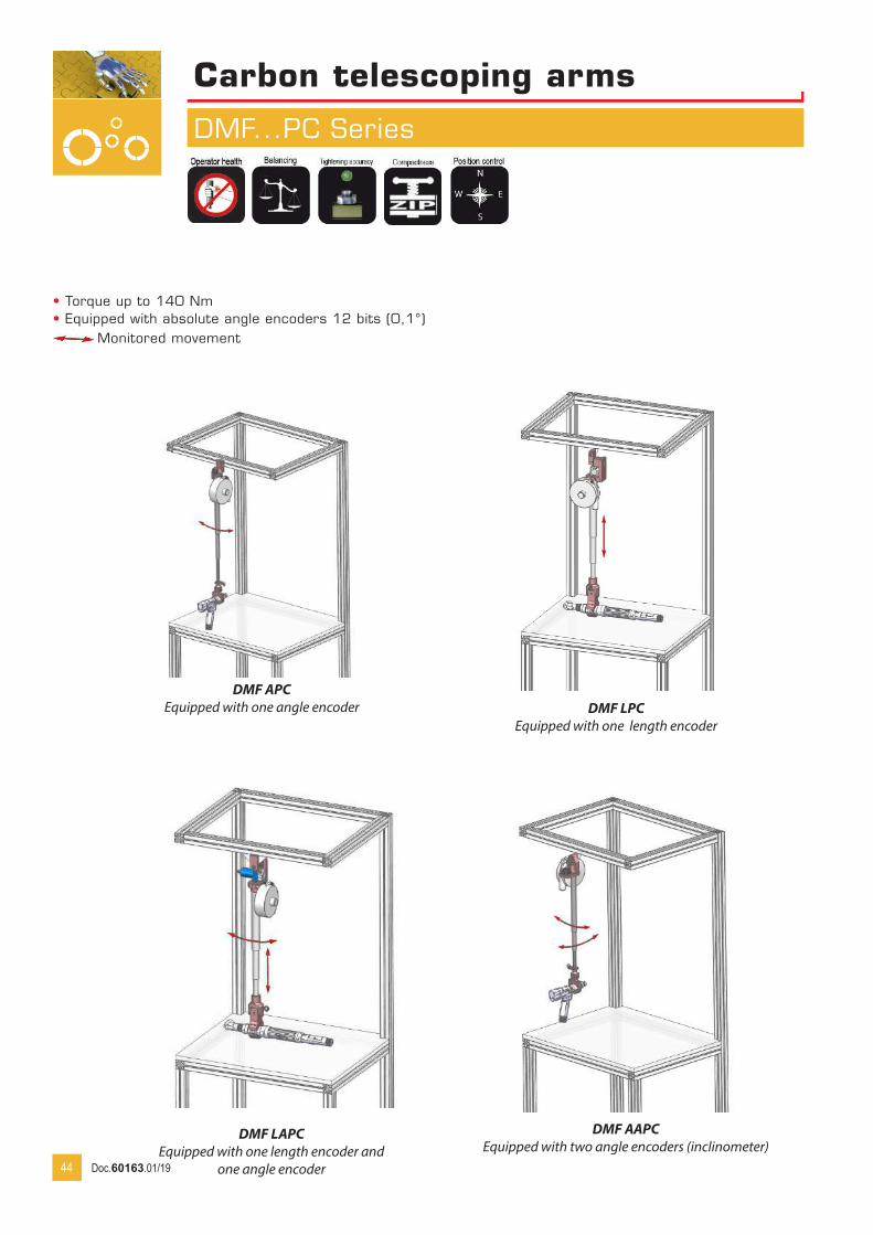
Monitored movement
Carbon telescoping arms
DMF...PC Series
DMF APCEquipped with one angle encoder DMF LPC
Equipped with one length encoder
DMF LAPCEquipped with one length encoder and
one angle encoder
DMF AAPCEquipped with two angle encoders (inclinometer)
44
• Torque up to 140 Nm• Equipped with absolute angle encoders 12 bits (0,1°)
Doc.60163.01/19

Carbon telescoping arms
DMF...PC Series
Model Torque Clamp Tool Ø Min Max Code without clamp Code with clampDMF 30 APC/960 30 P1 28-52 560 960 4-5200574 4-5200564DMF 30 APC/1500 30 P1 706 1500 4-5200575 4-5200565DMF 30 APC/2000 30 P1 873 2000 4-5200576 4-5200566DMF 80 APC/1500 80 P2/P3 35-52 764 1500 4-5200577 4-5200567DMF 80 APC/2000 80 P2/P3 930 2000 4-5200578 4-5200568DMF 140 APC/1500 140 P2/P3 978 1500 4-5200579 4-5200569DMF 140 APC/2000 140 P2/P3 1228 2000 4-5200580 4-5200572DMF 30 LPC/960 30 P1 28-52 560 960 4-5200588 4-5200581DMF 30 LPC/1500 30 P1 727 1500 4-5200589 4-5200582DMF 30 LPC/2000 30 P1 894 2000 4-5200590 4-5200583DMF 80 LPC/1500 80 P2/P3 35-52 780 1500 4-5200591 4-5200584DMF 80 LPC/2000 80 P2/P3 947 2000 4-5200592 4-5200585DMF 140 LPC/1500 140 P2/P3 991 1500 4-5200593 4-5200586DMF 140 LPC/2000 140 P2/P3 1241 2000 4-5200594 4-5200587DMF 30 LAPC/960 30 P1 28-52 560 960 4-5200662 4-5200595DMF 30 LAPC/1500 30 P1 727 1500 4-5200663 4-5200596DMF 30 LAPC/2000 30 P1 894 2000 4-5200664 4-5200597DMF 80 LAPC/1500 80 P2/P3 35-52 780 1500 4-5200665 4-5200598DMF 80 LAPC/2000 80 P2/P3 947 2000 4-5200666 4-5200599DMF 140 LAPC/1500 140 P2/P3 991 1500 4-5200667 4-5200660DMF 140 LAPC/2000 140 P2/P3 1241 2000 4-5200668 4-5200661
AAPC Option
DMF APC DMF LPC/LAPC
45
Inclinometer may be installed on standard DMF arms (DMF30, DMFi 70/120/200) to monitor angular position.
For CodeDMF 30 4-5200809DMFi 70/120/200 4-5200810
Doc.60163.01/19
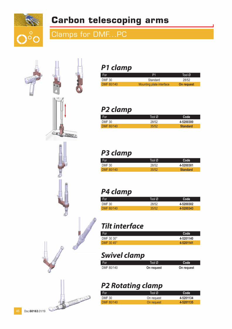
Carbon telescoping arms
Clamps for DMF...PC
P1 clampFor P1 Tool ØDMF 30 Standard 28/52DMF 80/140 Mounting plate interface On request
P2 clampFor Tool Ø CodeDMF 30 28/52 4-5200300DMF 80/140 35/52 Standard
P3 clampFor Tool Ø CodeDMF 30 28/52 4-5200301DMF 80/140 35/52 Standard
P4 clampFor Tool Ø CodeDMF 30 28/52 4-5200302DMF 80/140 35/52 4-5200343
Swivel clampFor Tool Ø CodeDMF 80/140 On request On request
P2 Rotating clampFor Tool Ø CodeDMF 30 On request 4-5201134DMF 80/140 On request 4-5201135
46
Tilt interfaceFor CodeDMF 30 30° 4-5201140DMF 30 45° 4-5201141
Doc.60163.01/19

Carbon telescoping arms
DMF...PC Accessories
Absorbing stop
Adjustable stop
Additional flange
Recommended in case of repeatable side shocks.Code 4-5201121 Set of 2
To limit the slide of the arm on the rail.Code 4-5200167
To reinforce the rail installation for high torque applications. Code 4-5200873
Rail linkTo link two rails together. Code 4-5200307
47
Rails
Rail interface
Length Stroke Number of flanges Code600 450 2 4-5200132800 650 2 4-5200160
1000 850 2 4-52001611200 1050 3 4-52001621500 1350 3 4-52001632000 1850 4 4-5200164
Allows installation of DMF on rail.For CodeDMF 30/80/140 4-5200341DMF 300 4-5200342NOTE : delivered without safety hook (Code 4-5200309)
Balancing kit for DMF...PCMax load tool (kg) For Code1/2,5 DMF 30 4-52003042/4 DMF 30/80 4-52003054/6 DMF 80/140 4-5200306
Balancer attachment kit for DMF30 Code 4-5201143.
Doc.60163.01/19

Monitored movement
Suspended arms
SLIDER BA...PC/RPC
SLIDER BA 12/25/40/100 RPC
48
Inclination adjustment in 3 positions
Maxi operating radius
• Torque up to 100 Nm• Operating range up to 900 mm• Equipped with 2 absolute encoders 12 bits (0,1°)• Higher torque available on request
Model Max torque (Nm) Tool Ø (mm)
Operating range (mm)
Stroke (mm)
Operating range (mm)
Max load (Kg)) Code
SLIDER BA 12 PC 12 27/50 420 195 1,2 4-5283120SLIDER BA 25 PC 25 28/52 420 195 2,2 4-5283121SLIDER BA 40 PC 40 28/52 420 295 3 4-5283122SLIDER BA 12 RPC 12 27/50 420 450 1,2 4-5201078SLIDER BA 25 RPC 25 28/52 420 460 2,2 4-5201079SLIDER BA 25 RPC/600 25 28/52 420 600 2,2 4-5201080SLIDER BA 40 RPC 40 28/52 420 650 3 4-5201081SLIDER BA 40 RPC/800 40 28/52 420 800 3 4-5201082SLIDER BA 100 RPC 100 28/52 420 730 4 4-5201083SLIDER BA 100 RPC/900 100 28/52 420 900 4 4-5201084
SLIDER BA 12/25/40 PC
Doc.60163.01/19

Suspended arms
SLIDER BA...RPC Dimensions
SLIDER BA 12/25/40/100 RPC
Dessiné par Date:17-04-13Rep Qté Ech: 1/1 Format: A4 Client:
Matière:
Traitement:
Plan N°:12-33-3765
Nom ensemble
Nom pièce
Tolérances générales: ±0.2 Ra 3.2Casser les angles vifs
N° Rév
ANote de révision
Emission originaleVérifié par GP
-Date
-
D
C
AB
Course verticale : 420
22.5°
A B min B max Operating range at 22,5° C D
SLIDER BA 12 RPC 261 102 252 474 380 440SLIDER BA 25 RPC 278 95 245 485 424 425SLIDER BA 25 RPC/600 336 305 330 607 447 425SLIDER BA 40 RPC 387,5 150 350 667 482 419SLIDER BA 40 RPC/800 470 415 415 801 496 419SLIDER BA 100 RPC 433 205 405 758 597 358SLIDER BA 100 RPC/900 528 470 520 908 634 358
49
Vertical stroke : 420
Doc.60163.01/19
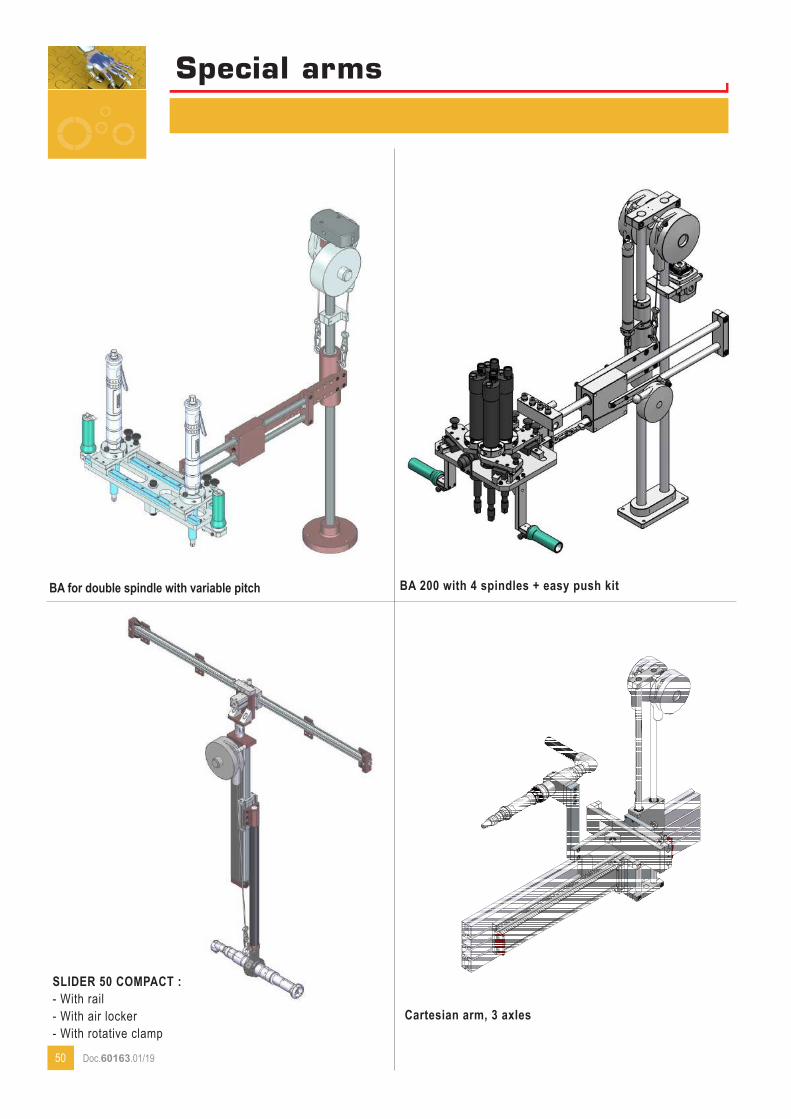
Special arms
BA 200 with 4 spindles + easy push kit
SLIDER 50 COMPACT :- With rail- With air locker- With rotative clamp
BA for double spindle with variable pitch
50
Cartesian arm, 3 axles
Doc.60163.01/19
Dessiné par Date:18-02-15Rep Qté Ech: 1/1 Format: A1 Client: RENAULT CLEON
Matière:Traitement:
Plan N°: 15-07-4053/2
Nom ensemble
Nom pièce
Tolérances générales: ±0.2 Ra 3.2Casser les angles vifs
N° Rév
DNote de révision
Mise à jourVérifié par GP
-Date
05-06-15
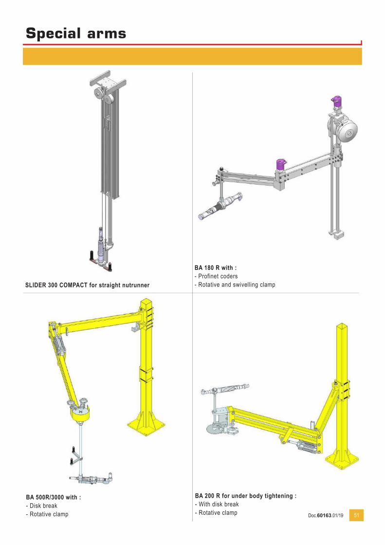
xxxxxSpecial arms
BA 180 R with :- Profinet coders- Rotative and swivelling clamp
BA 500R/3000 with :- Disk break- Rotative clamp
BA 200 R for under body tightening :- With disk break- Rotative clamp 51
SLIDER 300 COMPACT for straight nutrunner
Doc.60163.01/19
8, avenue Gutenberg - CS 5051078317 Maurepas Cedex - FranceTél. : +33 (0)1 30 66 41 20 • Fax : +33 (0)1 30 66 41 79 [email protected]
w w w . d o g a . f r
Doc.
6016
3.01
/19
Nous travaillons constamment à l’amélioration de nos produits. De ce fait, les dimensions et indications portées dans cette brochure peuvent parfois ne pas correspondre aux dernières exécutions. De convention expresse, nos ventes sont faites sous bénéfice de réserve de propriété (les dispositions de la loi du 12/5/80 trouvent donc toute leur application).