torque systems bmr2000_specsheet
TRANSCRIPT
Performance BenefitsTorque Systems specializes in the design of high performance brushservo motors that provide efficiency, flexibility of application, and along and trouble-free service life. Our TORQUEMASTER® 2000 series is no exception.
With fast response, accurate control and high torque-to-inertia ratios,you can count on the TORQUEMASTER 2000 Series of brush servomotors to provide smooth operation throughout a full speed range.The 2000 Series delivers smooth and superior low speed performance,and maximum power ratings with low thermal resistance for highspeed performance. In addition, with maximum torque in a smallerpackage, you can count on better pricing for a better overall value.
When integrated with high performance brush amplifiers, TORQUE-MASTER 2000 Series brush servo motors provide effective and highlyefficient motion control solutions for a wide range of applications—including factory automation, packaging, robotics, machine tools,medical instrumentation and more.
Design FeaturesTORQUEMASTER BMR 2000 Series servo motors are rated from 5 lb.-in. to 10lb.-in. with speeds and torque stability up to 10,000 RPM— accommodatingDC bus voltages up to 325 volts. They utilize the latest in high performanceNeodymium, permanent magnet technology, and are available in several standard windings (as well as custom windings) to meet your most demandingapplications.
Each servo motor in the TORQUE-MASTER 2000 Series is ruggedly designedand manufactured for reliable performance. To satisfy many different applications, TORQUEMASTER 2000 Series motors are manufactured toNEMA/IEC specifications..
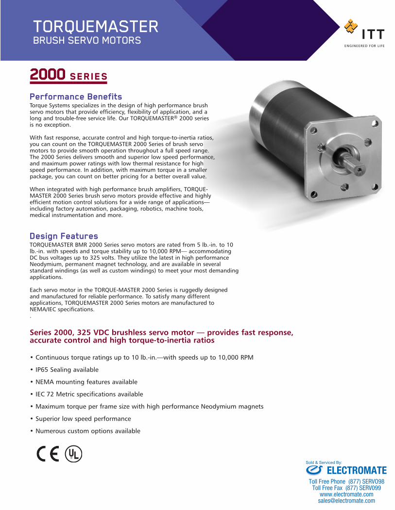
2000 SERIES
Series 2000, 325 VDC brushless servo motor — provides fast response,accurate control and high torque-to-inertia ratios
• Continuous torque ratings up to 10 lb.-in.—with speeds up to 10,000 RPM
• IP65 Sealing available
• NEMA mounting features available
• IEC 72 Metric specifications available
• Maximum torque per frame size with high performance Neodymium magnets
• Superior low speed performance
• Numerous custom options available
TORQUEMASTERBRUSH SERVO MOTORS
BMR_2000-BP:Brush series 2100 1/24/13 10:32 AM Page 2
ELECTROMATEToll Free Phone (877) SERVO98
Toll Free Fax (877) SERV099www.electromate.com
Sold & Serviced By:

BRUSHLESS SERVO MOTOR CHARACTERISTICSSYMBOL MOTOR PARAMETER UNITS BMR2005T BMR2010B
P Power KW .214 .35
Nm Max Operating Speed RPM 10,000 10,000
TC Max Stall Torque lb.-in.(Nm) 5 (.57) 10 (1.13)
TPk Peak Torque lb.-in.(Nm) 23 (2.6) 45 (5.1)
KT Torque Sensitivity lb.-in./AMP(Nm/Amp) .84 (.095) 2.53 (.286)
Ke Back E.M.F. Volts/Krpm 10 30
Ra Resistance Line to Line Ohms 1.61 3.69
L Inductance Line to Line MilliHenry 1.2 3.69
Jm Rotor Inertia lb.-in.-sec2 .0004 .0009(Kg-m2) .000045 .0001
TF Static Friction lb.-in.(Nm) .16 (.018) .16 (.018)
WT Motor Weight Lbs(Kg) 3.0 (1.35) 4.0 (1.8)
NOTE: Continuous torque specifications obtained with motor mounted to an 8.5”x12”x 0.25” aluminum plate at 25°C ambient. Typical values are within ±10% of rating. Relationship Between Ke & KT Torque Systems uses the following important motor performance parameters for the 3 phase square wave and 3 phase sine wave brushless motors in order to properly account for the British Imperial unit system currently used in the US.
Ke = Line-to-line volts-peak / Krpm*KT = Pound-inches (lb-in) / peak phase ampsKe is related to Kt as follows:KT = Ke/11.834 for 3 phase square wave current driven amplifiersKT = Ke/13.662 for 3 phase sinusoidal wave current driven amplifiers*Krpm = 1000 rpmFor “RMS” values, divide peak values by √2
STANDARD SPEED/TORQUE CURVE DATA FOR SIZING A SERVO MOTORNm = Maximum speed, continuous operationTcs = Continuous stall torque
All specifications subject to change without notice.
TORQUE PERFORMANCE CURVESNm
TcsTORQUE
SPEE
D
Continuous Duty Zone
Intermittent Duty Zone
BMR_2000-BP:Brush series 2100 1/24/13 10:22 AM Page 3
ELECTROMATEToll Free Phone (877) SERVO98
Toll Free Fax (877) SERV099www.electromate.com
Sold & Serviced By:

MECHANICAL SPECIFICATIONS*
DIMENSION CHART*(Dimensions may change based upon options)
AH
XDBB
AG
AKDIA.
U
.85
2.54
2.28 DIA.
R
A SQ.( “A” Mounting Shown )
A.005
A.002
-A-
.201 THRU (4) HOLES 90˚APART ON A 2.625 DIA. B.C.
Note: BMR 2000 Series is available with modular encoder option (not shown).Please consult factory.
TORQUE PERFORMANCE CURVES
PART NUMBER AG A AK BB U AH R XDDimension in inches
BMR2005 5.71 2.28 1.500 .06 .3750 .77 .357/.353 .70 FLAT
BMR2010 7.21 2.28 1.500 .06 .3750 .77 .357/.353 .70 FLAT
IEC72 (mm)
BMR2005 145.0 57.9 50j6 1.5 8j6 30 14 2.0
BMR2010 183.1 57.9 50j6 1.5 8j6 30 14 2.0
10002000300040005000600070008000
900010000
01 5 10 23 100
TORQUE (LB-IN)
Motor BMR2005 - Winding: T
SPEE
D (R
PM)
.11 .57 1.1 11.32.6TORQUE (Newton-Meters)
10002000300040005000600070008000
900010000
01 10 45 100
TORQUE (LB-IN)
Motor BMR2010 - Winding: B
SPEE
D (R
PM)
.11 1.1 11.35.1TORQUE (Newton-Meters)
NOTE: Dimension “AG” includes commutation feedback device and modular encoder shown on ordering information under COMMUTATION. For internal brake add 2.0" to dimension “AG”
TORQUE SPEED CURVES OF OTHER WINDINGS AVAILABLE, CONSULT FACTORY.
BMR_2000-BP:Brush series 2100 1/24/13 10:22 AM Page 4
ELECTROMATEToll Free Phone (877) SERVO98
Toll Free Fax (877) SERV099www.electromate.com
Sold & Serviced By:

Customize The 2000Series To Your ExactRequirements
To satisfy various applications withcost-effective solutions, 2000 Seriesmotors are readily available with awide range of standard capabilities.Final designs are often the result ofcooperative efforts between the customer’s engineering departmentand Torque Systems. For assistance,call your local distributor or TorqueSystems direct. We look forward tomeeting your custom requirements.
01/01 1M TS963R1-2000
ITT Torque Systems6 Enterprise RoadBillerica, MA 01821Tel: 978.667.5100 or 1.800.669.5112Fax: [email protected]
Notes:1. Standard BMR2000 motor mounting flanges use NEMA 23 standards but allow oversized shaft diameters to carry
the rated torque load. Standard NEMA shaft diameters are typically undersized for most servo ratings and are not recommended. Consult factory regarding acceptable load limits before ordering or applying this option.
2. The above motors include standard MS connectors. Connector mates or cables must be ordered separately.3. Standard encoders are dual channel line driver output with a marker pulse and complementary outputs.4. Brakes are for holding static loads and not designed to stop moving loads. Standard coils are 24 volts DC.
BMR ORDERING INFORMATION – (For Standard Options)BMR 2 006 T HA 0 0 P A A 000
FRAME SIZE2 = 2.28" Dia.
STALL TORQUE005 = 5 lb-in010 = 10 lb-in
WINDINGST = 10 V/KrpmA = 20 V/KrpmB = 30 V/Krpm
COMMUTATION/FEEDBACK (see note 3)HA = Hall Sensor onlyMO = Enc. Mtg. ProvisionsRA = Resolver size 15SR = Special Resolver
Commutating Line ModularEncoders Count Encoders*
CC = 500 PleaseCD = 1000CE = 1024 ConsultCF = 2500 SC = Special Factory
BRAKE (Internal) (see note 4)0 = NoneB = 24 VDC Coil
ENGINEERINGMODIFICATIONS
SEALING0 = NoneA = per IP65 w/o shaft sealB = per IP65 w/shaft seal
MOUNTING (see note 1)A = NEMA 23 Flange with 0.375"
Dia. x 0.77" long shaft w/flat (standard)C = “C” Face with 0.375" Dia. x 0.77"
long shaftD = NEMA 23 Flange with 0.250" Dia.
x 0.81" long shaft (Gear Box Mtg.) E = NEMA 23 Flange with 0.250" Dia.
x 0.77" long shaft w/flatM = Metric IEC72 Flange w/M8J6 shaftS = Special Flange and shaft
TERMINATIONSC = Connector MS3112E14-19PH = Heyco seal-tite w/1.5 ft shielded cableP = Pipe Tap (NPT) w/1.5 ft shielded cable
MATING CONNECTORS (see note 2)0 = NoneA = StraightB = Rt. AngleS = Special
EXAMPLE: BMR 2 005 T CD 0 0 C A A 000MODEL/FRAME ENGINEERING MODIFICATIONS
5 LB-IN STALL TORQUE SEALING
WINDING MOUNTING FEATURES
COMMUTATION TERMINATIONS
BRAKE MATING CONNECTORS
*Modular Encoder selection includes Hall Sensor Commutation
TERMINATION CHART
FEEDBACK OPTIONS(B STANDARD) MS3112E-14-19PPIN Com. Encoder Resolver Hall (Note 1)A Brake+ Brake+ Brake+B Brake- Brake- Brake-C – S2 (Sine+) –D – S4 (Sine-) –E Encoder A– – –F Encoder A – –G Hall U S1 (Cosine+) H1H Hall V S3 (Cosine-) H2J Hall W – H3 K Encoder 5V R1 (Excit.+) +5V to +24V L Encoder Com R2 (Excit.-) CommonM Ø M1 Ø M1 Ø M1N Ø M2 Ø M2 Ø M2P Ø M3 Ø M3 Ø M3R Encoder B– – –S Encoder B – –T Encoder M – –U Case Gnd. Case Gnd. Case Gnd.V Encoder M– – –
Note 1. Hall Sensor Specifications Voltage = 5V to 24VCurrent = 10 ma typical, 25 ma max.Output = Open collector
Note 2. Com. Encoder Current = 250 ma
BMR_2000-BP:Brush series 2100 1/24/13 11:32 AM Page 1
ELECTROMATEToll Free Phone (877) SERVO98
Toll Free Fax (877) SERV099www.electromate.com
Sold & Serviced By: