toshiba t1910 t1910cs - maintenance manual … t1910...the t 191 0 series computer is shown in...
TRANSCRIPT
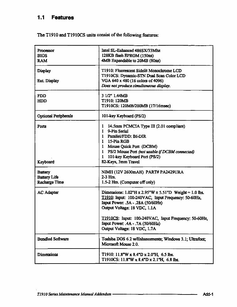
1.1 Features
The T1910 and T1910CS units consist of the following features:
Processor Intel SL-Enhanced 486SXl33Mhz BIOS 128KB flash EPROM (ISOns) RAM 4MB Expandable to 20MB (80ns)
Display T1910: Fluorescent Sidelit Monochrome LCD T1910CS: Dynamic-STN Dual Scan Color LCD
Ext. Display VGA 640 x 480 (16 colors of 4096) Does not produce simultaneous display.
FDD 3 1/2" 1.44MB lIDD T1910: 120MB
T1910CS: 120MB/200MB (17/16msec)
Optional Peripherals 10 I-key Keyboard (pS/2)
Ports I 14.Smm PCMCIA Type m (2.01 compliant) I 9-Pin Serial I ParallellFDD: BI-DIR. I IS-PinRGB I Mouse Quick Port (DCBM) I PS/2 Mouse" Port (not usable if DCBM connected) I 10 I-key Keyboard Port (pS/2)
Keyboard 82-Keys, 3mm Travel
Battery NIMH (12V 2600mAH) P ART# P A2429URA Battery Life 2-3 Hrs. Recharge Time 1.5-2 Hrs. (Computer off only)
ACAdapter Dimensions: 1.02"H x 2.9S"W x 5.5 I "D Weight = 1.0 lbs. Il2l.O: Input: 100-240VAC, Input Frequency: SO-60Hz, Input Power: .SA - .28A (SO/60Hz) Output Voltage: 18 VDC, I.IA
T1910CS: Input: lOO-240VAC, Input Frequency: SO-60Hz, Input Power: .4A - .7A (SO/60Hz) Output Voltage: 18 VDC, 1.7A
Bundled Software Toshiba DOS 6.2 w!EDhancements; Wmdows 3.1; Ultrafont; Microsoft Mouse 2.0.
Dimensions T1910: 11.8"W x 8.4"D x 2.0"H, 6.Slbs. T1910CS: 11.8"W x 8.4"D x 2.l''H, 6.8Ibs.
T1910 Series Maintenance Manual Addendum -------------- Add-1

The T 191 0 Series Computer is shown in Figure 1-1, and its system configuration is shown in Figure 1-2.
Add-2
Figure 1-1 T1910 Series Personal Computer
r---------------------------------------I
PJ8 PJ2 PJ5
PJ3
FA2SU· (T1910 PJ8 rr191OCS)
System PJ9 Board
PJ7
PJ4
PJ10 PJ1
PJ501
I I I I I I
Power Supply PJ502 PJ504
PJ503
---------------------------FA2SL· System Board
PJ203 PJ208
PJ202
pJ205 PJ204 PJ201
Figure 1-2 T1910 Series System Unit Configuration
Main Battery
Backup Battery
_______________ T1910 Series Maintenance Manual Addendum
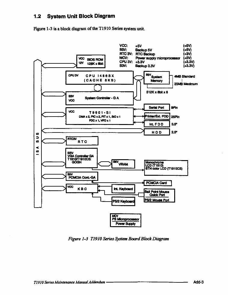
1.2 System Unit Block Diagram
Figure 1-3 is a block diagram of the T1910 Series system unit.
vee: +5V B5V: Backup 5V RTC 3V RTC 8acku : p
vee BIOS ROM MCV: Power supply microprocessor ~ 12Y 128Kx8bit CPU3V: +3.3V
K B3V: Backup3.3V
(+5V) (+5V) (+3V) (+5 (+3 (+3
V) .3V) .3V)
CPU3V CPU 1488SX k;) 83VSyatenI h4MBS
(CACHE 8KB) Memory i : I
() I j20MB
I I ---' < ') 512K x 8bIl x 8
B3V Syatem Controller - G A <-vee
Maximum
SerIal Port 9P1n vee T9901-SI
~ ) '-DMA x 2. PIC x2. PIT x 1. SIC x 1 text. FDD 25P1n FOe x 1. VFOx 1 ~
Int. FDD 3.5-
< ~ HOD 2.5" (IJ
~ RTC3V CD < RTC
c (IJ BSY - VGA ConInIIIr GA
T1910fT191OCS:
q85VYRAM I t" GOGH Monochrome LCD (T1910) STN color LCD (T191OCS)
C )lB5V I PCMCIA ConL-GA
.. PCMCIA C8rdl ~VCC K KBC h lint. Keyboard
r-- Ball Paint Mouse
~ _~P!'! __
1PS12 Keyboard i.-.
PS/2 McMe Port I
~
Figure 1-3 T1910SeriesSystemBoardBlockDiagram
T1910 Series Maintenance Manual Addendum --------------- Add-3

The T191 0 Series system board is composed of the following major components:
o An i486SX-33 CPU
o Super Integration (SI) T9901, which stores the following components:
• Two Direct Memory Access Controllers (DMAC): 82C37 • Two Programmable Interrupt Controllers (PIC): 82C59 • One Programmable Interval Timer (PIT): 82C54 • One Floppy Disk Controller (FOC): TC8565 • One Serial Input/Output Controller (SIO): TC8570 • One Variable Frequency Oscillator (VFO): TC8568 • One I/O Controller • One Printer Port Controller • One Speaker Controller
o A Real Time Clock (RTC)
One T9934 chip is used. The T9934 has 128 bytes of memory. Fourteen bytes of memory are used for the calendar and clock. The remaining 114 bytes are used for the system configuration data.
OSC (X3) generates 32.768 KHz for RTC.
o A Keyboard Controller (KBC)
One M37452M4 chip is used. This KBC includes the keyboard scan controller and keyboard interface controller. The KBC controls the internal keyboard, external keyboard port, PS/2 mouse port, and Ball Point Quick Port.
o The following memories:
Standard RAM: Cache memory: BIOS ROM:
4MB 8 KB (inside CPU) 128 KB (96 KB are used) This ROM contains Initial Reliability Test (lRT), Basic Input/Output System (BIOS), and video BIOS.
Video RAM: 256 KB Optional memory cards expand memory to a maximum. of20 MB.
o VGA display controller
Add-4
GOGH: This controller controls internal and external VGA compatible display.
OSC(X4) generates 28.322MHz for display controller. OSC(X5) generates 25. 175MHz for display controller.
--------------T1910 Series Maintenance Manual Addendum

o Clock Generator receives 14.31818 MHz (X2) and generates the following frequencies:
• 33 MHz for the CPU • 14.7456 MHz for the COM • 24 MHz for the FOC and VFO • 16 MHz is used for GA • 14.31818 MHz is used for T9901 (SI) • 4.77MHz is used for KBC
o GateArray
System Controller Gate Array
This gate array has the following functions:
• CPU Controller
• Memory Controller - DRAM Controller - Compatible Bus Interface Controller
• SM! Controller
• VL Bus Controller
• Bus Controller - Compatible Bus Interface Controller - Compatible Access Controller - DMAC Controller - I/O Controller
• Address Latch Controller - 32-Bit to 16-Bit Controller - Address Latch - DMA Address Generator - Refresh Address Generator
• 110 Register - Compatible I/O Port - Saving the data of the Register (in resume) Controller - Toshiba Special Register
• 33 MHzI16.5 MHz Controller • Data Bus Change Controller • DataLatch
PCMCIA Controller Gate Array
This gate array has the following functions:
• Memory Card Controller - PCMCIA Ie Card Controller - Toshiba Modem Card Controller
T1910 Series Maintenance Manual Addendum -------------- Add-5

1.3 3.S-inch Floppy Disk Drive
The T1910 Series 3.S-inch Floppy Disk Drive (FDD) is a thin, high-performance reliable drive that supports 720-KB (fonnatted) 2DD and I.44-MB (formatted) 2HD 3.S-inch floppy disks.
The T1910 Series FDD is shown in Figure 1-4, and specifications are listed in Table 1-1.
Figure 1-4 3.5-inch FDD
Table 1-1 3.5-inchFDD Specifications
Item 2-MBmode 1-MBmode
Storage capacity (1<8)
Unformatted 2,000 1,000 Formatted 1,311 737
Number of heads 2 2
Number of cylinders 80 80
Access time (ms) Track to track 3 3
Average 181 181
Head settling time 15 15
Recording track density (tpl) 135 135
Data transfer rate (Kbps) 500 250
Rotation speed (rpm) 300 300
Recording method Modified Frequency Modulation (MFM)
Add-6 --------------T1910 Series Maintenance Manual Addendum

1.4 2.S-inch Hard Disk Drive
The Hard Disk Drive (HOD) is a random access non-volatile storage device. It has a nonremovable 2.5-inch magnetic disk and mini-winchester type magnetic heads.
The T1910 Series supports a 120 MB or 200 MB HDD.
A T1910 Series HDD is shown in Figure 1-5, and specifications are listed in Table 1-2.
Figure 1-5 2.5-inch HDD
Table 1-2 2.5-inch HDD Specifications
120MB 200MB
(CP2124) (MK2124FC) (MK2224FC) (ST9235A)
Storage capacity (MB)
Formatted 121.6 130.1 213.0 209.7
Number of disks 2 2 2 3
Data heads 4 4 4 6
Data surfaces 4 4 4 6
Tracks per surface 1,123 1,155 1,560 985
Sectors per track 53 (+1) 55 (+1) - 32
Bytes per sector 512 512 512 512
Access time (ms)
Track to track 10 5 3 5
Average 17 17 12 16
Maximum 35 36 25 30
Rotation speed (rpm) 3,743 3,200 4,000 3449
Data transfer rate (bps)
Tolfrom media IBM 15.3 M 18.9 to 4M
31.6 M
Interleave 1 :1 1:1 1:1 1 :1
Recording method 2-7 RLL 1-7 RLL 1-7 RLL 1-7 RLL
T1910 Series Maintenance Manual Addendum ---------------- Add-7

1.5 Keyboard
The 82-(USA) or 84-(European) keyboard is mounted on the T1910 Series system unit, and is connected to the keyboard controller on the system board through a 19-pin flat cable. The keyboard is shown in Figure 1-6.
Figure 1-6 Keyboard
Add-a ________________ T1910 Series Maintenance ManuaJAtidentium

1.6 Monochrome LCD (T1910)
The monochrome Liquid Crystal Display (LCD) is composed of an LCD module, a Fluorescent Lamp (FL), and an FL inverter board.
1.6.1 Monochrome LCD Module
The T1910 monochrome LCD supports 64Ox480 pixels with a Video controller and 64 levels of gray. The video controller includes the functions of the Video Graphics Array (VGA).
The LCD receives vertical and horizontal synchronizing signals, 8-bit data signals (4-bit upper block data signals and 4-bit lower block data signals), and shift clock for data transmission. All signals are CMOS-level compatible.
The sidelit LCD is shown in Figure 1-7, and its specifications are listed in Table 1-3.
Figure 1-7 Monochrome LCD
Table 1-3 Monochrome LCD Specifications
Item Specifications
Number of Dots (dots) 640 x 480
Dot pitch (mm) 0.30 (W) x 0.30 (H)
Display area (mm) 198 (W) x 150 (H)
Contrast 17:1 (typically)
FLcurrent (rnA) 5.0
FL frequency (KHz) 42
T1910 Series Maintenance Manual Addendum -------------- Add-9
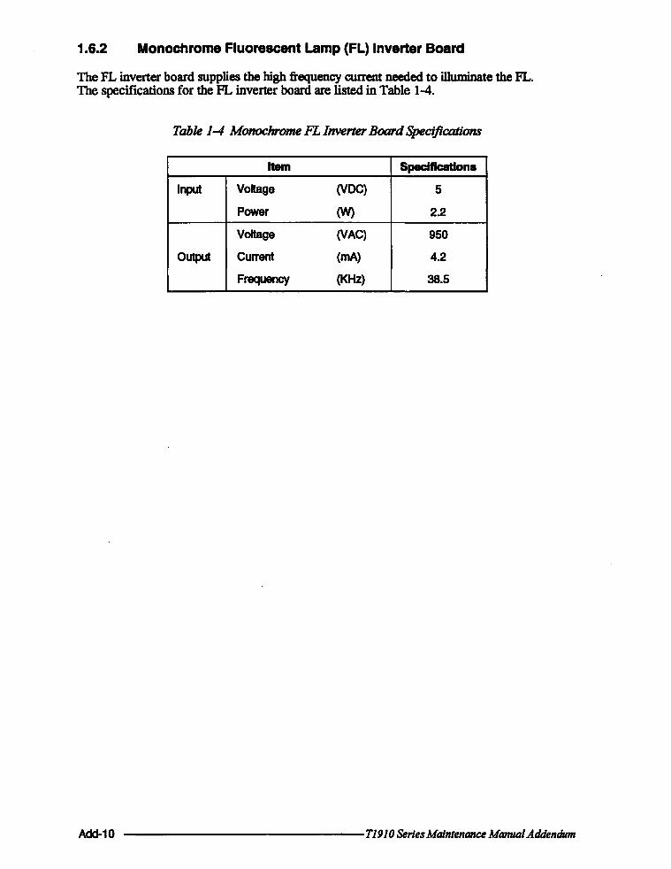
1.6.2 Monochrome Fluorescent Lamp (FL) Inverter Board
The FL inverter board supplies the high frequency current needed to illuminate the FL. The specifications for the FL inverter board are listed in Table 1-4.
Table 1-4 Monochrome FL Inverter Board Specifications
Item Specifications
Input Voltage (Voe) 5
Power (W) 2.2
Voltage (VAC) 950
Output Current (rnA) 4.2
Frequency (KHz) 38.5
Acld-10 ---------------T1910 Series Maintenance Manual Addendum
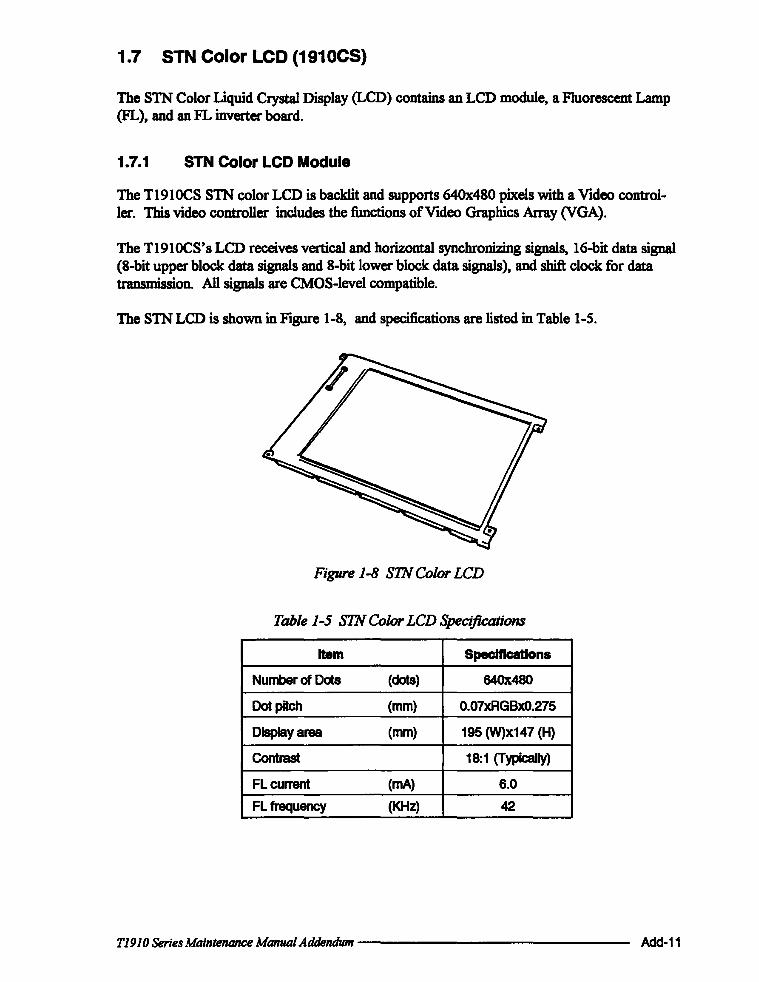
1.7 STN Color LCD (1910CS)
The STN Color Liquid Crystal Display (LCD) contains an LCD module, a Fluorescent Lamp (FL), and an FL inverter board.
1.7.1 STN Color LCD Module
The TI910CS STN color LCD is backlit and supports 640x480 pixels with a Video controller. This video controller includes the functions of Video Graphics Array (VGA).
The TI910CS's LCD receives vertical and horizontal synchronizing signals, 16-bit data signal (8-bit upper block data signals and 8-bit lower block data signals), and shift clock for data transmission. All signals are CMOS-level compatible.
The STN LCD is shown in Figure 1-8, and specifications are listed in Table 1-5.
Figure 1-8 STN Color LCD
Table 1-5 STN Color LCD Specifications
Item Specifications
Number of Dots (dots) 640x480
Dot pitch (mm) 0.07xAGBxO.275
Display area (mm) 195 (W)x147 (H)
Contrast 18:1 (Typically)
FLcurrent (rnA) 6.0
FL frequency (KHz) 42
T1910 Series Maintenance Manual Addendum -------------- Acld-11

1.7.2 STN Color Fluorescent Lamp (FL) Inverter Board
The FL inverter board supplies high frequency current to light the LCD's Fluorescent Lamp. The specifications for the FL inverter are listed in Table 1-6.
Table 1-6 STH Color FL Inverter Board Specifications
Item Specifications
Input Voltage (VOC) 5
Power (W) 6
Output Voltage (VAC) 1,100
Current (rnA) 6.0
Frequency (KHz) 42
Add-12 ---------------T1910 Series Maintenance Manual Addendum

1.8 Power Supply
The power supply uses a power supply microprocessor to monitor and regulate the voltages used within the T1910 Series computers. It contains the following functions:
1. Determines if the AC adapter or battery is connected to the computer.
2. Detects DC output and circuit malfunctions.
3. Controls the LED indicator and speaker.
4. Turns the battery charging system on and offand detects a fully charged battery.
5. Determines if the power can be turned on and off.
6. Provides more accurate detection of a low battery.
7. Calculates the remaining battery capacity.
The power supply output rating is specified in Table 1-7.
Table 1-7 Power Supply Output Rating
DC Regulation Maximum
Use for Name voltage tolerance currant Ripple
(V) (%) (mA) (mY)
System logic, FDD, HOD, VCC +5 ±5 3,500 100
Display
RS-232C, Flash ROM 12V +12 ±5 120 240
RAM,CPU 83V +3.3 ±5 755 66
RS-232C M12V -7to-12.6 - 10 -
T1910 Series Maintenance Manual Addendum --------------- Add-13

1.9 Batteries
The T1910 Series has three types of batteries:
o Main battery pack o Backup battery o Real Tune Clock (RTC) battery
Specifications for these batteries are listed in Table 1-8.
Table 1-8 Battery Specifications
Battery name Material Output voltage Capacity
Main battery Nickel Metal Hydride 12V 2,600mAH
Backup battery Nickel Metal Hydride 1.2V 1,100mAH
RTe battery Lithium-Vanadium 3.0 V 50mAH
1.9.1 Main Battery
The removable main battery pack is the computer's main power source when the AC adapter is not attached. The main battery recharges the backup battery when the system's power is on. The backup and main battery maintain the state of the computer when you enable AutoResume.
Add-14
a Battery Indicator
The Battery indicator is located on the top cover, and shows the status of the removable battery pack, power supply and AC adapter.
The status of each can be determined by color:
Orange The battery is being charged. (AC adapter is attached.)
Green The battery is fully charged. (AC adapter is attached.)
No light The AC adapter is disconnected from the computer or the AC adapter is connected, but it cannot charge the battery for one of the following reasons:
o
o
o
The battery is extremely hot. Allow the computer and the battery to reach room temperature before attempting to charge the battery.
The battery is almost fully discharged. The battery will not begin charging immediately in this state, it will begin charging a few minutes after the AC adapter is connected.
The AC adapter is not receiving power.
--------------TI9IO Series Maintenance Manual Addendum

1.9.2 Battery Charging Control
Battery charging is controlled by a microprocessor that is mounted on the power supply. The microprocessor controls whether the charge is on or off and detects a full charge when the AC adapter and battery are attached to the computer. The system charges the battery using quick charge or trickle charge.
When the AC adapter is attached, there are two types of charge: quick charge when the system is powered off and trickle charge when the system is powered on.
Table 1-9 Time Required For Battery Charges
Charging time
Quick charge About 2.3 hours (T191 0) (power off) About 1.4 hours (T191 OCS)
Trickle charge About 48 hours (power on)
Cl Quick Battery Charge
If the one of the following occurs, the battery quick-charge process stops.
1. The battery becomes fully charged
2. The AC adapter or battery is removed.
3. The battery or AC adapter output voltage is abnormal.
4. The charge current is abnormal.
a Trielde Battery Charge
When the main battery is fully charged and the AC adapter is attached, the power supply microprocessor automatically changes quick charge to trickle charge.
T1910 Series Maintenance Manual Addendum --------------- Add-15

1.9.3 Backup Battery
The backup battery maintains data for AutoResume. The power source used to back-up the AutoResume data is detennined according to the following priority:
AC adapter> Main battery> Backup battery
The backup battery is charged by the main battery or AC adapter when the system is powered on. Table 1-10 shows the charging time and data preservation period of the backup battery.
Table 1-10 Backup Battery CharginglData. Preservation Time
Time
Charging Time Power On 16H
Power Off (with AC Adapter) 60H
Power Off (Without AC Adapter) Doesn't charge
Data preservation period (full charge) 8H
1.9.4 RTC Battery
The RTC battery provides power to keep the current date, time and other setup information in memory while the computer is turned off. Table 1-11 shows the charging time and data preservation period of the RTC battery.
Table 1-11 RTC Battery CharginglData Preservation Time
Time
Charging Time Power On 48H
Power Off Doesn't charge
Data preservation period (full charge) 1 month
Add-16 ---------------T1910 Series Maintenance Manual Addendum