toshiba thermal printer trst-56 series€¦ · 570 ohito, izunokuni-shi, shizuoka-ken, japan <...
TRANSCRIPT

TOSHIBA Thermal Printer
TRST-56 SERIES
Owner's Manual

CE Compliance (for EU only)
This product complies with the requirements of EMC and Low Voltage Directives including their amendments.
WARNING This is a Class A product. In a domestic environment this product may cause radio interference in which case the user may be required to take adequate measures.
ATTENTION Ce produit est de classe A. Dans un environnement domestique, il peut causer des interférences radio. Auquel cas, l’utilisateur sera amené à prendre les mesures adéquates.
Warnung Dies ist ein Klasse A Produkt. In einer örtlichen Umgebung kann dieses Gerät Funkstörungen verursachen.
Atención Este es un producto de la clase A. En ambientes domésticos éste producto puede causar radio interferencias en cuyo caso el usuario deberá tomar las medldas oportunas.
VERWITTIGING Dit is een klasse A produkt. Het gebruik hiervan kan radio interferenties veroorzaken die de gebruiker ertoe kunnen dwingen sommige maatregelen te moeten treffen.
Schallemission: unter 70dB(A) nach DIN 45635 (ISO7779)
FCC Notice This equipment has been tested and found to comply with the limits for a Class A digital device, pursuant to Part 15 of the FCC Rules. These limits are designed to provide reasonable protection against harmful interference when the equipment is operated in a commercial environment. This equipment generates, uses, and can radiate radio frequency energy and, if not installed and used in accordance with the instruction manual, may cause harmful interference to radio communications. Operation of this equipment in a residential area is likely to cause harmful interference in which case the user will be required to correct the interference at this own expense. Changes or modifications not expressly approved by manufacturer for compliance could void the user’s authority to operate the equipment.
Copyright © 2004 by TOSHIBA TEC CORPORATION All Rights Reserved 570 Ohito, Izunokuni-shi, Shizuoka-ken, JAPAN
< For EU Only > TOSHIBA TEC Europe Retail Information Systems S.A. Rue de la Célidée 33 BE-1080 Brussels

Safety Summary EO1-13018
( ) i
6DIHW\�6XPPDU\� Personal safety in handling or maintaining the equipment is extremely important. Warnings and Cautions necessary for safe handling are included in this manual. All warnings and cautions contained in this manual should be read and understood before handling or maintaining the equipment. Do not attempt to effect repairs or modifications to this equipment. If a fault occurs that cannot be rectified using the procedures described in this manual, turn off the power, unplug the machine, then contact your authorised TOSHIBA TEC representative for assistance. 0HDQLQJV�RI�(DFK�6\PERO�
This symbol indicates warning items (including cautions). Specific warning contents are drawn inside the symbol. (The symbol on the left indicates a general caution.) This symbol indicates prohibited actions (prohibited items). Specific prohibited contents are drawn inside or near the symbol. (The symbol on the left indicates “no disassembling”.) This symbol indicates actions which must be performed. Specific instructions are drawn inside or near the ● symbol. (The symbol on the left indicates “disconnect the power cord plug from the outlet”.)
This indicates that there is the risk of death or serious injury if the machines are improperly handled contrary to this indication.
Do not use voltages other than the voltage (AC) specified on the rating plate, as this may cause fire or electric shock.
Do not plug in or unplug the power cord plug with wet hands as this may cause electric shock.
If the machines share the same outlet with any other electrical appliances which consume large amounts of power, the voltage will fluctuate widely each time these appliances operate. Be sure to provide an exclusive outlet for the machine as this may cause the machines to malfunction.
Do not place metal objects or water-filled containers such as flower vases, flower pots or mugs, etc. on top of the machines. If metal objects or spilled liquid enter the machines, this may cause fire or electric shock.
Do not insert or drop metal, flammable or other foreign objects into the machines through the ventilation slits, as this may cause fire or electric shock.
Do not scratch, damage or modify the power cords. Also, do not place heavy objects on, pull on, or excessively bend the cords, as this may cause fire or electrical shock.
If the machines are dropped or their cabinets damaged, first turn off the power switches and disconnect the power cord plugs from the outlet, and then contact your authorised TOSHIBA TEC representative for assistance. Continued use of the machine in that condition may cause fire or electric shock.
Continued use of the machines in an abnormal condition such as when the machines are producing smoke or strange smells may cause fire or electric shock. In these cases, immediately turn off the power switches and disconnect the power cord plugs from the outlet. Then, contact your authorised TOSHIBA TEC representative for assistance.
:$51,1*�
$Q\ RWKHU WKDQ WKHVSHFLILHG $& YROWDJHLV SURKLELWHG�
3URKLELWHG
3URKLELWHG
3URKLELWHG
3URKLELWHG
3URKLELWHG
'LVFRQQHFWWKH SOXJ�
'LVFRQQHFWWKH SOXJ�

Safety Summary EO1-13018
( ) ii
If foreign objects (metal fragments, water, liquids) enter the machines, first turn off the power switches and disconnect the power cord plugs from the outlet, and then contact your authorised TOSHIBA TEC representative for assistance. Continued use of the machine in that condition may cause fire or electric shock.
When unplugging the power cords, be sure to hold and pull on the plug portion. Pulling on the cord portion may cut or expose the internal wires and cause fire or electric shock.
Ensure that the equipment is properly grounded. Extension cables should also be grounded. Fire or electric shock could occur on improperly grounded equipment.
Do not remove covers, repair or modify the machine by yourself. You may be injured by high voltage, very hot parts or sharp edges inside the machine.
This indicates that there is the risk of personal Injury or damage to objects if the machines are improperly handled contrary to this indication.
Precautions
The following precautions will help to ensure that this machine will continue to function correctly. ● Try to avoid locations that have the following adverse conditions: * Temperatures out of the specification * Direct sunlight * High humidity * Shared power source * Excessive vibration * Dust/Gas ● The cover should be cleaned by wiping with a dry cloth or a cloth slightly dampened with a mild
detergent solution. NEVER USE THINNER OR ANY OTHER VOLATILE SOLVENT on the plastic covers.
● USE ONLY TOSHIBA TEC SPECIFIED paper and ribbons. ● DO NOT STORE the paper or ribbons where they might be exposed to direct sunlight, high
temperatures, high humidity, dust, or gas. ● Ensure the printer is operated on a level surface. ● Any data stored in the memory of the printer could be lost during a printer fault. ● Try to avoid using this equipment on the same power supply as high voltage equipment or equipment
likely to cause mains interference. ● Unplug the machine whenever you are working inside it or cleaning it. ● Keep your work environment static free. ● Do not place heavy objects on top of the machines, as these items may become unbalanced and fall
causing injury . ● Do not block the ventilation slits of the machines, as this will cause heat to build up inside the
machines and may cause fire . ● Do not lean against the machine. It may fall on you and could cause injury . ● Care must be taken not to injure yourself with the printer paper cutter. ● Unplug the machine when it is not used for a long period of time.
Request Regarding Maintenance
● Utilize our maintenance services. After purchasing the machine, contactii your authorised TOSHIBA TEC representative for assistance
once a year to have the inside of the machine cleaned. Otherwise, dust will build up inside the machines and may cause a fire or a malfunction. Cleaning is particularly effective before humid rainy seasons.
● Our preventive maintenance service performs the periodic checks and other work required to maintain the quality and performance of the machines, preventing accidents beforehand.
For details, please consult your authorised TOSHIBA TEC representative for assistance.
● Using insecticides and other chemicals Do not expose the machines to insecticides or other volatile solvents. This will cause the cabinet or other parts to deteriorate or cause the paint to peel.
&$87,21�
'LVFRQQHFWWKH SOXJ�
&RQQHFW DJURXQGLQJ ZLUH�
'LVFRQQHFWWKH SOXJ�
1RGLVDVVHPEOLQJ�

EO1-13018
TABLE OF CONTENTS
Page
1. PRODUCT OVERVIEW-------------------------------------------------------------------------------- 1- 1
1.1 Introduction-------------------------------------------------------------------------------------------------1- 1
1.2 Features-----------------------------------------------------------------------------------------------------1- 1
1.3 Applicable Model------------------------------------------------------------------------------------------1- 1
1.4 Accessories ------------------------------------------------------------------------------------------------1- 2
2. SPECIFICATIONS -------------------------------------------------------------------------------------- 2- 1
2.1 Printer -------------------------------------------------------------------------------------------------------2- 1
2.2 Receipt Roll ------------------------------------------------------------------------------------------------2- 2
3. APPEARANCE------------------------------------------------------------------------------------------- 3- 1
3.1 Front/Rear View-------------------------------------------------------------------------------------------3- 1
3.2 Operation Panel-------------------------------------------------------------------------------------------3- 1
3.3 Connectors -------------------------------------------------------------------------------------------------3- 2
4. SET UP PROCEDURE--------------------------------------------------------------------------------- 4- 1
4.1 Requirements for Operation----------------------------------------------------------------------------4- 1
4.2 Setting up the Printer ------------------------------------------------------------------------------------4- 2
5. INSTALLATION PROCEDURE --------------------------------------------------------------------- 5- 1
5.1 Connecting the Power Cord and Interface Cable -------------------------------------------------5- 1
5.2 Connecting the Drawer ----------------------------------------------------------------------------------5- 3
5.3 Loading the Receipt Roll --------------------------------------------------------------------------------5- 3
5.4 Adjusting the Paper Near End Sensor Position----------------------------------------------------5- 4
5.5 Self Test Print----------------------------------------------------------------------------------------------5- 5
6. GENERAL MAINTENANCE-------------------------------------------------------------------------- 6- 1
6.1 Cleaning ----------------------------------------------------------------------------------------------------6- 1
6.1.1 Cleaning the Print Head and Platen --------------------------------------------------------6- 1
6.1.2 Cleaning the Covers----------------------------------------------------------------------------6- 1
6.2 Removing Jammed Paper ------------------------------------------------------------------------------6- 1
7. TROUBLESHOOTING --------------------------------------------------------------------------------- 7- 1
CAUTION!
1. This manual may not be copied in while or in part without prior written permission of TOSHIBA TEC.
2. The contents of this manual may be changed without notification. 3. Please refer to your local Authorised Service representative with regard to any queries you
may have in this manual.
1. PRODUCT OVERVIEW EO1-13018
1.1 Introduction
1- 1
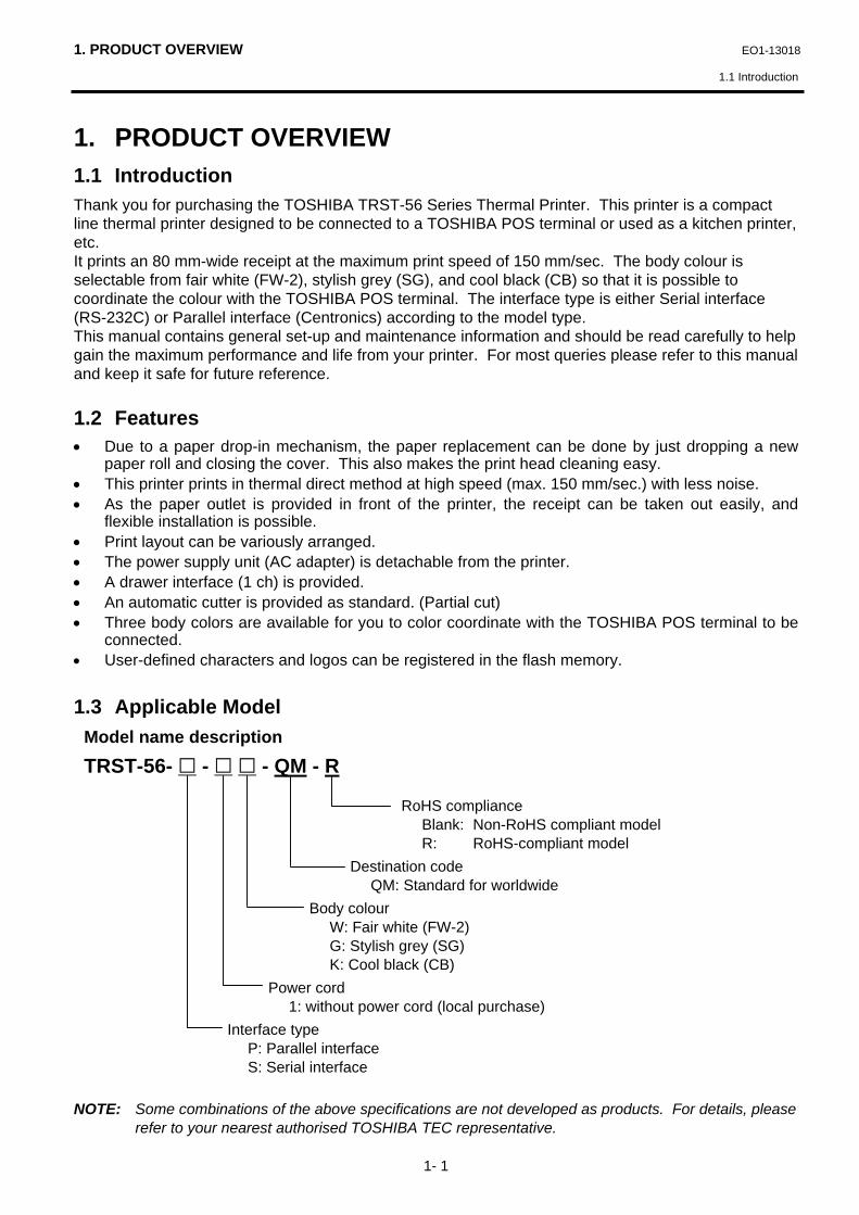
1. PRODUCT OVERVIEW 1.1 Introduction Thank you for purchasing the TOSHIBA TRST-56 Series Thermal Printer. This printer is a compact line thermal printer designed to be connected to a TOSHIBA POS terminal or used as a kitchen printer, etc. It prints an 80 mm-wide receipt at the maximum print speed of 150 mm/sec. The body colour is selectable from fair white (FW-2), stylish grey (SG), and cool black (CB) so that it is possible to coordinate the colour with the TOSHIBA POS terminal. The interface type is either Serial interface (RS-232C) or Parallel interface (Centronics) according to the model type. This manual contains general set-up and maintenance information and should be read carefully to help gain the maximum performance and life from your printer. For most queries please refer to this manual and keep it safe for future reference. 1.2 Features • Due to a paper drop-in mechanism, the paper replacement can be done by just dropping a new
paper roll and closing the cover. This also makes the print head cleaning easy. • This printer prints in thermal direct method at high speed (max. 150 mm/sec.) with less noise. • As the paper outlet is provided in front of the printer, the receipt can be taken out easily, and
flexible installation is possible. • Print layout can be variously arranged. • The power supply unit (AC adapter) is detachable from the printer. • A drawer interface (1 ch) is provided. • An automatic cutter is provided as standard. (Partial cut) • Three body colors are available for you to color coordinate with the TOSHIBA POS terminal to be
connected. • User-defined characters and logos can be registered in the flash memory. 1.3 Applicable Model
Model name description TRST-56- - - QM - R
RoHS compliance Blank: Non-RoHS compliant model R: RoHS-compliant model Destination code QM: Standard for worldwide Body colour W: Fair white (FW-2) G: Stylish grey (SG) K: Cool black (CB) Power cord 1: without power cord (local purchase) Interface type P: Parallel interface S: Serial interface NOTE: Some combinations of the above specifications are not developed as products. For details, please
refer to your nearest authorised TOSHIBA TEC representative.

1. PRODUCT OVERVIEW EO1-13018
1.4 Accessories
1- 2
1.4 Accessories NOTES:
1. The partition is provided for a case of using a 58 mm-wide receipt roll only. 2. The enclosed receipt roll is provided for an operation test.
TOSHIBA Thermal Printer
TRST-56 SERIESOwner's Manual
Owner’s Manual (1 copy) Receipt Roll (1 pc.) Partition (1 pc.)

2. SPECIFICATIONS EO1-13018
2.1 Printer
2- 1
2. SPECIFICATIONS 2.1 Printer
Item Description
Printing method Line thermal dot printing method
Printing width 72 mm (576 dots)
Resolution 8x8 dots/mm (203 dpi)
Printing speed Max. 150 mm/sec. (1,200 dot lines/sec.)
Printing columns Font A (12 x 24 dots): 48/42 columns Font B (9 x 24 dots): 64/56 columns
Character size Font A: 1.25 x 3.00 mm Font B: 0.88 x 3.00 mm
Character types Alpha-numerals, International characters, Code pages PC850, PC852, PC857, PC860, PC863, PC865, PC866 and Windows code page
Logo registration and print User defined characters and logos are registerable in the flash memory.
Line spacing 4.23 mm (1/6 inch): selectable using the commands
Printable bar codes UPC-A/E, EAN 13/8, ITF, CODE39, CODE128, CODABAR, CODE93
Cut method Partial cut
Paper Thermal paper roll: 80 mm x ∅83
Interface Serial (RS-232C) or Parallel (Centronics)
Input buffer 4K bytes/72 bytes
Supply voltage AC 100 - 240V ±10%, 50/60Hz
Power consumption 1 – 0.55A
AC adapter specification Rated input: AC 100 - 240V, 50/60Hz, 1 - 0.55A Rated output: DC 24V, 1.9A
Body colour Fair white (FW2) or Stylish grey (SG) or Cool black (CB)
Operating temperature 0°C to 40°C (Operation is guaranteed.) 5°C to 40°C (Print quality is guaranteed.)
Operating humidity 20% to 90% RH (no condensation)
Storage temperature -20°C to 60°C
Storage humidity 10% to 90% RH (no condensation)
Weight 2Kg (with AC adapter), 1.4 Kg (without AC adapter)
Dimension 145 mm (W) x 190 mm (D) x 157 mm (H): with AC adapter box 145 mm (W) x 190 mm (D) x 114 mm (H): without AC adapter box

2. SPECIFICATIONS EO1-13018
2.2 Receipt Roll
2- 2
2.2 Receipt Roll
Paper type Thermal paper rolled with the print side facing outside Width (W) 80 +0/-1 mm Outer diameter (D) 80 +0.5/-1 mm Paper thickness (T) 0.075±0.005 mm Weight 69±3g/m2 Outer core diameter 18 mm Inner core diameter 12 mm Recommended thermal paper Only paper rolled onto a core is acceptable, however, the paper end
should not be pasted to the core. Normal paper: PD150R OHJI PAPER (Japan) Long storable paper: PD152R OHJI PAPER (Japan)
• Do not store the paper for longer than the manufacturer’s recommended shelf life. • Store the paper in a cool, dry place. Avoid areas where they would be exposed to direct sunlight,
high temperature, high humidity, dust or gas. • A contact of chemical or oil may discolour or erase the printed record. • Rubbing the paper hard with nail or hard object may discolour the paper. • The paper end should not be pasted to the core. For further information please contact your authorised TOSHIBA TEC representative or authorised paper manufacturer.
CAUTION! Use only paper which meets specified requirements. Use of non-specified paper may shorten the head life of the printer, resulting in problems with print quality, cause a paper feed failure or shorten the cutter life. All paper should be handled with care to avoid any damage to the paper. Read the following guideline carefully.
Width (W)
Inner corediameter (ID)
Outer corediameter (OD)
Outerdiameter (D)
Paperthickness (T)
3. APPEARANCE EO1-13018
3.1 Front/Rear View
3- 1
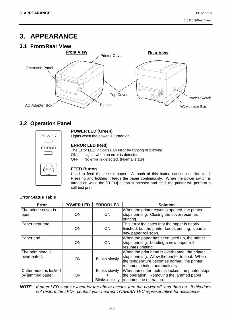
3. APPEARANCE 3.1 Front/Rear View 3.2 Operation Panel
POWER LED (Green) Lights when the power is turned on. ERROR LED (Red) The Error LED indicates an error by lighting or blinking. ON: Lights when an error is detected. OFF: No error is detected. (Normal state) FEED Button Used to feed the receipt paper. A touch of this button causes one line feed. Pressing and holding it feeds the paper continuously. When the power switch is turned on while the [FEED] button is pressed and held, the printer will perform a self test print.
Error Status Table
Error POWER LED ERROR LED Solution The printer cover is open. ON ON
When the printer cover is opened, the printer stops printing. Closing the cover resumes printing.
Paper near end ON ON
This error indicates that the paper is nearly finished, but the printer keeps printing. Load a new paper roll soon.
Paper end ON ON
When the paper has been used up, the printer stops printing. Loading a new paper roll resumes printing.
The print head is overheated. ON Blinks slowly
When the print head is overheated, the printer stops printing. Allow the printer to cool. When the temperature becomes normal, the printer resumes printing automatically.
Cutter motor is locked by jammed paper. ON
Blinks slowly +
Blinks quickly
When the cutter motor is locked, the printer stops the operation. Removing the jammed paper resumes the operation.
NOTE: If other LED status except for the above occurs, turn the power off, and then on. If this does not restore the LEDs, contact your nearest TOSHIBA TEC representative for assistance.
Rear View
Power Switch
AC Adapter Box
POWER
ERROR
FEED
Front View
Operation Panel
Top Cover
AC Adapter Box
Printer Cover
Ejector

3. APPEARANCE EO1-13018
3.3 Connectors
3- 2
3.3 Connectors
c�[Interface connector] (Serial interface model: D-SUB 25-pin Socket Connector,
Parallel interface model: IEEE 1284-B receptacle) An interface cable which connects the printer to a POS terminal is connected to this connector.
A Centronics interface cable (Parallel I/F model) or an RS-232C interface cable (Serial I/F model) is connected.
d [Drawer interface connector] (6-pin modular connector) A drawer cable which connects the printer to a drawer is connected to this connector. To this
connector, a TOSHIBA drawer can be connected. Do not connect anything other than the connectable drawer.
NOTE: For the connectable drawers, refer to your nearest authorised TOSHIBA TEC representative.
e [DC24V] (Socket connector) The built-in AC adapter supplies +24V power to the printer through this connector. Do not connect
anything other than the built-in AC adapter. f�[AC Inlet] The AC power cord is connected to this inlet. g [Ground terminal] The drawer interface cable’s ground wire is secured to this terminal.
CAUTION! 1. The drawer interface connector is exclusively for connecting the drawer. Do not connect a
phone line or any other cables than the drawer cable to this connector. Doing so may cause afailure of the phone line and this printer.
2. To the DC24V connector (socket connector), do not connect anything other than the built-inAC adapter.
3. The built-in AC adapter is exclusively for this printer. Do not use it for any other machines.
d e
f
g c

4. SET UP PROCEDURE EO1-13018
4.1 Requirements for Operation
4- 1
4. SET UP PROCEDURE 4.1 Requirements for Operation This printer has the following requirements:
Serial interface Type • The TOSHIBA POS terminal to be connected must have a serial port. • To communicate with the TOSHIBA POS terminal, an RS-232C interface cable is required. RS-232C cable ....... 25 pins Parallel Interface Type • The TOSHIBA POS terminal to be connected must have a Centronics parallel port. • To communicate with the TOSHIBA POS terminal, a Centronics interface cable is required. Centronics cable..... 36 pins Interface Cables For the serial interface model, use the RS-232C cable which satisfies the following pin configuration and the specification of the connector. For the parallel interface model, use the Centronics cable which satisfies the following pin configuration and the specification of the connector. To prevent the emission and receipt of electrical noise, the interface cable must meet the following requirements: • Fully shielded and fitted with metal or metalized connector housings. • Kept as short as possible. • Should not be tightly bundled with the power cord. • Should not be tied to power line conduits. RS-232C cable pin configuration POS terminal side Printer side D-SUB 9-pin female D-SUB 25-pin male
PIN No. Signal PIN No. Signal Case FG 1 FG
2 RXD 2 TXD 3 TXD 3 RXD 8 CTS 4 RTS 4 DTR 6 DSR 5 GND 7 GND 6 DSR 20 DTR
Centronics cable pin configuration POS terminal side Printer side D-SUB 25-pin male IEEE1284-B receptacle
PIN No. Signal PIN No. Signal 1 /STROBE 1 /STROBE
2-9 PD1-8 2-9 PD1-8 10 /ACK 10 /ACK 11 BUSY 11 BUSY 12 PERROR 12 PERROR 13 SELECT 13 SELECT 14 /AUTOFD 14 /AUTOFD 16 /INIT 31 /INIT 15 /FAULT 32 /FAULT 17 /SELECTIN 36 /SELECTIN
18-25 GND 19-30 GND 15-18 N.C. 33-35 N.C.
NOTES: 1. For details of the interface cable, contact your nearest TOSHIBA TEC representative. 2. In the country supposed to enforce the RoHS directive, use RoHS-compliant cables for a
RoHS-compliant product.

4. SET UP PROCEDURE EO1-13018
4.2 Setting up the Printer
4- 2
4.2 Setting up the Printer 1) Make sure that the printer power is turned OFF. 2) Connect the interface cable to the printer. 3) Insert the power cord into the AC inlet. 4) Connect the interface cable to a TOSHIBA POS terminal, and plug in the power cord to the AC
outlet. 5) If a drawer is desired to be connected, connect the drawer interface cable to the printer. 6) Secure the drawer ground wire to the ground terminal on the rear of the printer. 7) Turn the printer power ON. 8) Open the printer cover. 9) Load the receipt roll into the printer. 10) Close the printer cover. One receipt will be automatically issued. 11) Check the print quality by performing a self test print. Now the printer is ready for printing. NOTES:
1. For details of the above steps 1) to 4), refer to Section 5.1 Connecting the Power Cord and Cables .
2. Steps 5) and 6) are the procedures of the drawer connection. For details of Steps 5) and 6), refer to Section 5.2 Connecting the Drawer .
3. For details of Steps 8) to 10), refer to Section 5.3 Loading the Receipt Roll . 4. For details of Step 11), refer to Section 5.5 Self Test .
CAUTION! 1. Place the printer on a flat, stable surface. 2. Do not place the printer close to a heater or where it may be exposed to direct sunlight. 3. Avoid locations where the printer may be exposed to high temperature, high humidity or dust. 4. Care must be taken that no condensation occurs in the printer. If it should, however, do not
turn ON the power until the condensation is dried. 5. Use a grounded electrical outlet. Do not use an adapter plug. 6. Be sure that there is adequate room around the printer for easy operation and maintenance. 7. Keep your work environment static free.

5. INSTALLATION PROCEDURE EO1-13018
5.1 Connecting the Power Cord and Interface Cable
5- 1
5. INSTALLATION PROCEDURE
5.1 Connecting the Power Cord and Interface Cable 1) Turn the printer power OFF. 2) Insert the power cord into the AC inlet.
WARNING!
1. Since the power cord and the interface cable are not provided with this unit, please locally purchase ones which meet the specifications. For detail specifications, please contact your nearest authorised TOSHIBA TEC representative.
2. Before connecting the power cord and cables to the printer, turn the power of the POS terminal and printer OFF.
3. Do not pull the power cord hard. Doing this may damage the power cord, causing fire, electric shock, or broken wire.
4. When it thunders, unplug the power cord. Lightning stroke may cause fire or electric shock. 5. Keep the power cord away from a heater. The cover of the power cord may be melted,
causing fire or electric shock. 5. Do not connect the power cord to the AC outlet provided on the POS terminal such as ST-
5600, ST-5500, etc.
CAUTION! 1. Be sure to hold the connector when plugging in or unplugging the AC adapter cable. 2. Insert the AC adapter cable and the power cord firmly.
AC Inlet
Power Cord
AC Adapter Cable
CAUTION! 1. When separating the AC adapter, please contact your authorized TOSHIBA TEC
representative. 2. The built-in AC adapter is exclusively for this printer. Do not use it for any other machines. 3. The AC adapter can be used indoors only. Never use it outdoors. 4. Be sure to unplug the printer when it is not used for a long time. 5. Do not share the power source with other electric appliances which generate noise.

5. INSTALLATION PROCEDURE EO1-13018
5.1 Connecting the Power Cord and Interface Cable
5- 2
3) Connect and secure the interface cable to the interface connector in the correct orientation. Serial interface: Secure the connector with the screws. Parallel interface: Secure the connector with the locking tabs. 4) Connect the interface cable to the TOSHIBA POS terminal, and then plug in the power cord to the
AC outlet. NOTE: The above figure shows the example of the interface cable which is connected to the LPT1
port (Parallel interface) on the ST-5600 POS terminal.
Serial Interface Connector
Serial Interface Cable
Parallel Interface Cable
Parallel Interface Connector
Locking Tab
[Serial Interface Type] [Parallel Interface Type]
LPT1
Interface Cable
Locking Tab

5. INSTALLATION PROCEDURE EO1-13018
5.2 Connecting the Drawer
5- 3
5.2 Connecting the Drawer 1) Turn the printer power OFF. 2) Connect the drawer cable to the drawer interface connector in the correct orientation. 3) Secure the ground wire of the drawer to the ground terminal on the rear of the printer. NOTE: A TOSHIBA drawer can be connected to the drawer interface connector. Regarding the
connectable drawers, please contact your authorised TOSHIBA TEC representative.
5.3 Loading the Receipt Roll When you use this printer for the first time or when the receipt paper has been used up, load a receipt roll in the following procedures while the printer power is set to ON. A thermal printer prints thermal receipt paper by applying heat to the paper to react with the chemicals on the paper surface. A red line which appears on the reverse side of the receipt paper indicates that the paper is almost used up.
CAUTION! The drawer interface connector is exclusively for connecting a drawer. Do not connect a phone line or any other cables than the specified drawer cable. Doing so may cause a failure of the phone line and the printer.
Drawer Interface Connector
Drawer Cable
Ground Wire
WARNING!
The print head becomes very hot while printing. Never touch the print head to avoid getting burned.
CAUTION! 1. Use only TOSHIBA TEC specified paper. Use of non-specified paper may shorten the print
head life resulting in problems with print quality, cause a paper feed failure, or shorten the cutter life.
2. Do not subject the thermal receipt roll to water, oil, or heat source as this will darken the paper. 3. Load the receipt roll in the correct orientation. Failure to do this may cause a paper jam error. 4. Care must be taken not to damage the print head and platen when the printer cover is opened
as this may cause a poor print or a printer failure. 5. Do not open the printer cover while the printer is printing. 6. Do not hold the receipt while the printer is printing. Doing so may cause a paper jam. 7. When closing the printer cover, do not press it down too hard. 8. Do not put anything on the printer cover or push the cover too strongly. Doing so may cause a
print failure.
Ground Terminal

5. INSTALLATION PROCEDURE EO1-13018
5.4 Adjusting the Paper Near End Sensor Position
5- 4
1) Turn the printer power ON. 2) Press down the ejector to unhook the printer cover. (c) 3) Hold both sides of the printer cover and open it until it stops.(d) 4) Check for the correct orientation of the receipt roll, and put it into the paper holder. 5) Pull the receipt until it extends past the paper outlet for about 5 cm (e), and then close the printer
cover by pressing it’s front centre gently and make sure that the ejector snaps up. 6) Excessive paper will be automatically fed and cut.
5.4 Adjusting the Paper Near End Sensor Position 1) Press down the ejector to unhook the printer cover. Hold both sides of the printer cover and open
it until it stops. 2) Push the sensor tab in the direction of the arrow (c) to unhook the sensor tab. Adjust the sensor
unit position (d) by moving the sensor tab according to the remaining volume of the receipt paper. 3) The following table shows an outline of the relationship between the remaining volume of the
receipt paper and the sensor position. (when using the specified paper roll)
Sensor position Remaining volume
(Outer roll diameter: mm) 1 ∅18 2 ∅21 3 ∅24 4 ∅27
2
3
1
Print Head Printer Cover
Ejector
Caution symbol for hot surface. (Please refer to the WARNING! on the previous page.)
CAUTION! 1. The remaining volume of roll paper (outer roll diameter) varies depending on the printer models
and paper types. Please use the following table just for your reference. 2. Do not open the DIP switch cover under the paper holder or change the DIP switch settings.
Changing the settings may cause a malfunction of the printer.
1234
2
1
Sensor Tab
Sensor Unit DIP Switch Cover
Sensor Position
Receipt Roll

5. INSTALLATION PROCEDURE EO1-13018
5.5 Self Test Print
5- 5
5.5 Self Test Print When the power is turned on while pressing the [FEED] button, the printer will start a self test print. After completing the self test print, the printer will automatically cut the receipt and return to the stand-by mode. (while the printer is restored, the POWER LED goes off for a moment and soon lights again.) If the [FEED] button is kept pressed while the printer is restored, the self test print will be performed again.
TRST-56 MPVX.XX LPVX.XX
Serial InterfaceBaud Rate : 9600 bpsData Bit : 8 bitsParity : OddHandshake : DTR/DSR
Buffer Size : 4K byte
Dip SwitchesDS1
1 2 3 4 5 6 7 8ON o oOFF o o o o o o
DS21 2 3 4 5 6 7 8 9 10
ONOFF o o o o o o o o o o
DS31 2 3 4 5 6 7 8
ON oOFF o o o o o o o
!” #$%&’ ()*+-./0123456789:;<=>?@ABCDEFGHIJKLMNOPQRSTUVWXYZ[ ] ^ _ ‘abcdefghijklmnopqrstuvwxyz{|}~
Firmware VersionLoader Version
Interface Type
Communication Specification(Serial Interface model only)
Buffer Size
Dip Switch Settings(Different dependingon the destination)Dip Switch 3 settingsare printed for the SerialInterface model only)
Printable Characters(Different dependingon the destination)

6. GENERAL MAINTENANCE EO1-13018
6.1 Cleaning
6- 1
6. GENERAL MAINTENANCE
To help retain the high quality and performance of your printer it should be cleaned regularly. The greater the usage on the printer, the more frequent the cleaning. (i.e. low usage=weekly, high usage=daily)
6.1 Cleaning
6.1.1 Cleaning the Print Head and Platen
1) Turn the power OFF and open the printer cover. 2) Clean the print head element (cross hatched area
in the figure on the right) with a cotton swab slightly moistened with alcohol.
3) Clean the platen with a soft cloth moistened with alcohol.
6.1.2 Cleaning the Covers
Wipe the covers with a soft dry cloth or soft cloth slightly moistened with mild detergent. After using detergent for cleaning, be sure to wipe it off with a slightly moistened cloth.
6.2 Removing Jammed Paper 1) Turn the power OFF. 2) Open the printer cover. 3) Remove the jammed paper. DO NOT USE any sharp implement or tool as these will damage the
printer. 4) Clean the print head and platen, then remove any further dust or foreign objects. 5) Re-load the receipt roll. (Refer to Section 5.3 Loading the Receipt Roll .) 6) After closing the printer cover, turn the power ON. The printer will initialise the auto cutter to
restore the printer stand-by.
NOTE: If the jammed paper cannot be removed, remove the receipt roll from the printer, and turn the power ON while pressing and holding the [FEED] button. The cutter will move to the center so that the jammed paper can be removed easily.
WARNING!
1. Be sure to disconnect the power cord prior to performing any maintenance. 2. DO NOT POUR WATER directly onto the printer, as this may cause electric shock or fire. 3. The print head becomes very hot while printing. To avoid getting burned, never touch the print
head during the maintenance.
CAUTION! 1. Do not use any sharp object to clean the print head and platen. Doing so may damage them,
causing poor print or missing dots. 2. Never use an organic solvent like thinners or benzene for cleaning. Using such solvents may
discolour the covers. 3. Do not touch the print head element as static built-up may damage the print head.
Caution symbol for hot surface. (Please refer to the WARNING! on the above.)
Print Head Element
Platen

7.TROUBLESHOOTING EO-13018
7. TROUBLESHOOTING
7- 1
7. TROUBLESHOOTING
Problem Check Pint Solution The power is not turned on. (Power LED does not light.)
• Is the power cord plugged in correctly?
• Is the power supplied to the AC outlet?
• Has the circuit breaker
tripped?
• Plug it in correctly. • If it is not a power failure, check if the
power is supplied to the AC outlet with another electric appliance. If not, contact your nearest power company.
• Check the circuit breaker.
Receipt paper is not issued.
• Is the receipt roll loaded properly?
• Does a paper jam error occur?
• Refer to Section 5.3 and load the receipt roll properly.
• Refer to Section 6.2 and remove the jammed paper, and re-load the receipt roll.
No printing is performed though the POWER LED lights.
• Is the interface cable connected correctly?
• Does the specification of the interface cable meet that of the POS terminal or the printer?
• Connect the interface cable correctly. • Use a TOSHIBA TEC-recommended
interface cable or an interface cable which meets the specification of the printer.
Issued receipt paper is stained.
• Is the print head dirty? • Refer to Section 6.1 and clean the print head.
Irregular print/blurred print
• Is the proper paper used? • Is the paper dampened?
• Refer to Section 2.2 and use the TOSHIBA TEC specified paper.
• Do not use dampened paper. NOTE: If any problem occurs other than the above, please contact your authorised TOSHIBA TEC
representative.
WARNING!
If you cannot solve a problem with the following solutions, do not attempt to repair it by yourself. Turn the power off, unplug the printer, then contact your authorised TOSHIBA TEC representative for assistance.

INDEX EO1-13018
INDEX
INDEX
A AC adapter ........................................1-1, 2-1 AC adapter cable...................................... 5-1 AC adapter box ........................................ 3-1 Accessories.............................................. 1-2 C Character size .......................................... 2-1 Character types ........................................ 2-1 Centronics cable pin configuration............ 4-1 Cleaning................................................... 6-1 Connector................................................. 3-2 Parallel interface model ....................... 3-2 Serial interface model.......................... 3-2 Cut method............................................... 2-1 D Dimension ................................................ 2-1 DIP switch cover....................................... 5-4 Drawer ..................................................... 5-3 Drawer cable ............................................ 5-3 Drawer interface connector................3-2, 5-3 E Ejector...............................................3-1, 5-4 Error status table ...................................... 3-1 I Inner core diameter ................................. 2-2 Interface ................................................... 2-1 Interface cable.......................................... 4-1 J Jammed paper ......................................... 6-1
O Operation Panel .......................................3-1 ERROR LED .......................................3-1 FEED Button .......................................3-1 POWER LED.......................................3-1 Outer core diameter..................................2-2 Outer diameter (D) ...................................2-2 P Paper thickness (T) ..................................2-2 Paper type................................................2-2 Parallel interface type...............................4-1 Partition....................................................1-2 Platen.......................................................6-1 Power consumption..................................2-1 Power switch ............................................3-1 Print head.................................................5-4 Printer cover.............................................3-1 Printing method ........................................2-1 Printing speed ..........................................2-1 R Receipt roll ........................................2-2, 5-4 RS-232C cable pin configuration ..............4-1 S Self test print ............................................5-5 Serial interface type..................................4-1 Specifications ...........................................2-1 Sensor tab................................................5-4 T Top cover .................................................3-1 Troubleshooting........................................7-1 W Weight (Printer) ........................................2-1 Weight (Receipt roll) .................................2-2 Width (W) .................................................2-2

English
Waste Recycling information for users: Following information is only for EU-member states: The crossed out wheeled bin symbol is used to indicate that the product must not be treated as general household waste. By ensuring that this product is disposed of correctly you will be helping to prevent potentially negative consequences for the environment and human health, which could otherwise be caused by incorrect waste handling of this product. For more detailed information about the take-back and recycling of this equipment, please contact the supplier that provided you with the product in question. French
Information aux utilisateurs concernant le recyclage des déchets: Les informations suivantes sont uniquement destinées aux pays membres de l L’utilisation du symbole de "poubelle à roulettes barrée" indique que ce produit ne doit pas être traité comme un déchet
En vous assurant que ce produit est correctement mis au rebut, vous participerez à la prévention de la santé publique, contre des conséquences négatives potentielles qui pourraient résulter d’un traitement inapproprié des déchets de ce produit. Pour obtenir des informations complémentaires concernant la récupération et le recyclage de ce produit, veuillez contacter le fournisseur auprès duquel vous avez acheté le produit. German
Wiederverwertungsinformationen für Verbraucher: Die folgenden Informationen gelten nur für EU-Mitgliedsstaaten: Das durchgestrichene Mülltonnensymbol weist darauf hin, dass dieses Produkt nicht wie allgemeiner Haushaltsmüll behandelt werden darf. Indem Sie aktiv mitwirken, dieses Produkt ordnungsgemäß zu entsorgen, helfen Sie mit, mögliche negative Auswirkungen auf die Umwelt sowie die menschliche Gesundheit zu vermeiden, die sonst durch die unsachgemäße Entsorgung dieses Produktes beeinträchtigt werden könnten. Für nährere Informationen zur Rücknahme und Wiederverwertung dieses Produktes wenden sie sich bitte an den Lieferanten, von dem Sie dieses Produkt erworben haben. Spanish
Información para usuarios sobre el reciclaje de residuos: La siguiente información sólo concierne a los Estados Miembros de la UE: El uso del símbolo de un contenedor con ruedas tachado indica que este producto no puede ser tratado como si fuera un residuo doméstico. Asegurando que nos deshacemos de este producto de forma correcta, ayudaremos a evitar potenciales consecuencias negativas tanto para el medio ambiente como para la salud pública, que podrían producirse debido a un tratamiento inapropiado de este producto. Para obtener una información más detallada sobre la recogida y reciclaje de su producto, por favor, póngase en contacto con el proveedor donde lo compró. Dutch
Gebruikersinformatie over het recycleren van afval: De volgende informatie geldt enkel in EU-lidstaten: Het symbool met de doorkruiste afvalbak geeft aan dat dit product niet mag worden behandeld als algemeen huishoudelijk af val. Door dit product op de juiste manier van de hand te doen beschermt u het milieu en de volksgezondheid tegen mogelijke negatieve gevolgen, die anders zouden kunnen voortvloeien uit het onjuist verwerken van de resten van dit product. Voor gedetailleerde informatie over het terugnemen en recycleren van dit product, gelieve contact op te nemen met de leverancier van dit product. Italian
Informazioni sul riciclo del prodotto: Le seguenti informazioni riguardano gli stati membri EU: Il simbolo con il bidone sbarrato indica il non poter smaltire questo prodotto come rifiuto domestico. L'accertamento che questo prodotto sia smaltito correttamente contribuirà ad impedire le potenziali conseguenze negative per l'ambiente e la salute umana che potrebbero essere causati, al contrario, dall'errato smaltimento dello stesso. Per informazioni più dettagliate sulle modalita di resa e riciclaggio di questo prodotto mettetevi in contatto con il fornitore da cui l'avete aquistato. Portuguese
Informação sobre reciclagem: A informação que se segue é apenas dirigida a países membros da CEE: A utilização deste símbolo indica que este produto não pode ser tratado como lixo comum. Ao assegurar-se que este produto é tratado correctamente está a ajudar a prevenir potenciais consequências negativas para o ambiente e para a saúde humana, que poderiam ser causadas pelo inapropriado tratamento deste produto. Para mais informação sobre a reciclagem e tratamento deste produto, contacte o seu fornecedor.

E PRINTED IN JAPAN EO1-13018C