towards the internet of underground things: a systematic
TRANSCRIPT

1
Towards the Internet of Underground Things: ASystematic Survey
Nasir Saeed, Member, IEEE, Tareq Y. Al-Naffouri, Senior Member, IEEE, Mohamed-Slim Alouini, Fellow, IEEE
Abstract—This paper provides recent advances in the areaof Internet of Underground Things (IoUT) with emphasis onenabling communication technologies, networking issues, andlocalization techniques. IoUT is enabled by underground things(sensors), communication technology, and networking protocols.This new paradigm of IoUT facilitates the integration of sensingand communication in the underground environment for variousindustries such as oil and gas, agriculture, seismic mapping, andborder monitoring. These applications require to gather relevantinformation from the deployed underground things. However,the harsh underground propagation environment including sand,rock, and watersheds do not allow the use of single communi-cation technology for information transfer between the surfaceand the underground things. Therefore, various wireless andwired communication technologies are used for undergroundcommunication. The wireless technologies are based on acousticwaves, electromagnetic waves, magnetic induction and visiblelight communication while the wired technologies use coaxialcable and optical fibers. In this paper, state-of-art communicationtechnologies are surveyed, and the respective networking andlocalization techniques for IoUT are presented. Moreover, theadvances and applications of IoUT are also reported. Also, newresearch challenges for the design and implementation of IoUTare identified.
Index Terms—Internet of Underground Things, communica-tion, networking, localization, survey
I. INTRODUCTION
The population of the world will increase by 31 % in 2050,and therefore will require more natural resources and food tosurvive. In the next three decades with such increase in popu-lation, 71 % more resources are required. This ever-increasingdemand for resources needs novel technologies to improve theunderground exploration for natural resources and to producemore crop. The subsurface environment and agricultural landsprovide various natural resources such as earth minerals, fossilfuels, metal ores, groundwater, and food. To efficiently use allof these resources, Internet of Underground Things (IoUT)is an enabling technology which can provide smart oil andgas fields, smart agriculture fields, and smart seismic qualitycontrol. However, implementation of IoUT is a challengingtask due to the harsh underground environment which requireslow power and small size underground sensors, long-rangecommunication technology, efficient networking solutions, andaccurate localization techniques.
The research on channel characteristics for IoUTs is richwhere the primary communication sources are electromagnetic
This work is supported by Office of Sponsored Research (OSR) at KingAbdullah University of Science and Technology (KAUST).
The authors are with the Computer Electrical and Mathematical Sciences& Engineering (CEMSE) Division, KAUST, Thuwal, Makkah Province,Kingdom of Saudi Arabia, 23955-6900.
waves (EM), acoustic waves, magnetic induction (MI), mudpulse telemetry, coaxial cable, and fiber optics. The significantdifference between the in air internet of things and IoUT is thecommunication media where the sensors (underground things)are buried and communicate through the soil. Due to the het-erogeneous nature of the soil which consists of sand, rock, andwatersheds, communication through it is more challenging.Watersheds have a notoriously bad impact on EM waves-basedunderground communication systems (UGCSs) by limiting itstransmission range. Among the other alternatives, acousticwaves-based UGCSs provide an extended transmission rangebut suffers from low data rates, i.e., in few bits per second.To improve the data rate, MI has been investigated in the pastdecade which can provide high-speed underground commu-nication but has low transmission range and depends on theorientation of the transmitter and receiver coils. Mud pulsetelemetry is also an enabling technology for data transmissionfrom the down-hole to the surface which uses pressure pulsesfor information coding. The maximum data rate of 3-6 bitsper second can be achieved with mud pulse telemetry whichis low and needs to be further investigated for providing highbandwidth communication. Wired telemetry which includescoaxial cable and fiber optics is another alternative for UGCSswhich provide data rate up to 57,600 bits per second at theexpense of extra cost and complexity. Table I compares variouscommunication technologies for IoUT.
A. Related Surveys
There are quite few survey articles published that cover var-ious issues of IoUTs. For example, the work in [1] presents theEM waves based IoUTs for precise agriculture. Moreover, [1]also reviews the academic testbeds and commercial solutionsfor precise agriculture. In [2], the authors give an overview ofMI-based underground wireless sensor networks and presentchallenges and applications. The authors in [3], present therecent advances and challenges for wireless sensor networksin the oil and gas industry. The contributions of this articlerelative to the existing literature on IoUT is summarized asfollows:• Compared to existing papers for IoUTs, this paper pro-
vides a deeper understanding of the all relevant commu-nication technologies, networking solutions, and localiza-tion techniques which can be used to implement variousIoUT-based applications.
• The existing surveys only presents the literature on EMand MI-based underground wireless communication net-works. However, we also collect the research on acoustic,
arX
iv:1
902.
0384
4v1
[ee
ss.S
P] 1
1 Fe
b 20
19

2
TABLE I: Comparison of underground communication technologies for IoUT.
Parameters EM Acoustic Mud pulse MI WiredTransmissionRange
few meters In hundred of meters In hundred of me-ters
In tens of meters In hundred of me-ters
Attenuation High High Medium Low LowInterference High Medium Medium Low LowInstallation cost Medium Medium Low Medium LowData rate In tens of bps In tens of bps In tens of bps In Kbps In MbpsApplications Agriculture, seismic
exploration, and down-holetelemetry
Seismic exploration, buriedpipeline monitoring, anddown-hole telemetry
Down-holetelemetry
Down-holetelemetry
Down-holetelemetry andburied pipelinemonitoring
Section IIEM-based IoUT
Section IIIAcoustic-based
IoUT
Section IVMud Pulse-based
IoUT
Section VMI-based IoUT
Section VIIVLC-based IoUT
Section VIWired IoUT
Applications
Section VIIIChallenges for IoUT
Channel modelling
Networking
Localization
Fig. 1: Organization of the survey.
mud-pulse telemetry, visible light, and wired-based com-munication technologies for various IoUT applications.
• We survey the key challenges to implement IoUT andexplore the relationship between IoUT, big data analytics,cloud, and fog computing.
B. Survey Organization
The main focus of the paper is to review channel modeling,networking, and localization methods for the current sensingand communication technologies used in IoUT. However,for some of the techniques such as acoustic, visible lightcommunications, and mud-pulse telemetry, the networking,and localization problem is still an open research problem.Fig. 1 illustrate the organization of the survey. In Section II,we present the literature on EM-based communication andnetworking solutions for IoUTs. Sections III and IV coveracoustic and mud pulse-based IoUTs respectively. MI, visiblelight, and wired based solutions are presented in section V,
VI, and VII respectively. Section VIII discusses the advancesand challenges of IoUTs. Finally, section IX summarizes andconcludes the survey.
II. EM WAVES FOR IOUT
EM waves are widely used for underground communicationand sensing to enable various applications such as smartagriculture [4]–[7], seismic exploration [8], and oil and gasreservoirs monitoring [9]–[11]. Fig. 2 shows the major ap-plications of EM-based IoUT. In this section, we cover theliterature on the channel modeling and networking for EM-based IoUTs.
A. Channel Modeling
Channel modelling for EM-based underground communica-tions dates back to the early 70’s of the 20th century. Jameset. al investigated the propagation of EM signals through theearth surface where the frequency range of 1 to 10 MHz

3
TABLE II: Summary of channel modeling for EM-based IoUT.
Ref. Data rate Frequency range Issue addressed Applications Year[12] - 1-10 MHz Propagation characteris-
ticsSeismic/Agriculture 1971
[13] - - Structure of soil effect onEM waves propagation
Seismic/Agriculture 1973
[14] and [15] - 3-50 MHz Electrical characteristicsof soil
Seismic/Agriculture 1974 and 1976
[16] 1-100 bps - EM waves for boreholecommunications
Oil and Gas 1990
[17] - 1-3 MHz Impact of soil and net-work parameters
Agriculture 1990
[18] - 300-500 MHz Impact of soil type Agriculture 2009[19] - - development of the path
loss modelAgriculture 2010
[20] - - Test-bed Agriculture 2010[21] - 0.1-120 THz Channel model Oil and Gas 2012[22]–[24] - below 500 KHz Propagation characteris-
ticsAgriculture 2012
[25] - 10-100 MHz Energy harvesting Seismic/Agriculture 2012[26]–[28] - 433 MHz Propagation characteris-
ticsAgriculture 2014-2016
[29] 124 Mbps 433 MHz multi-carrier modulationfor EM-based IoUT
Agriculture 2017
[30] - 97-130 MHz Soil moisture sensing Agriculture 2018
Smart seismic exploration
Smart drilling
Smart agriculture
Smart Oil and Gas fields
EM-based IoUT Solutions
Fig. 2: Applications of EM-based IoUT
was experimentally tested in different types of soil [12]. Theauthors in [13] further examined the impact of different layersof the soil on the propagation of EM signals where Fast FourierTransform was used to find the reflection of the incidentsignals from a three-layered medium. Furthermore, Lytle et. almeasured the electrical characteristics of the earth medium forthe propagation of underground EM signals [14]. The authorsin [15] experimentally measured the conductivity of the earthsurface at EM frequencies of 3 to 50 MHz at Yosemite nationalpark. William et. al measured high-frequency electromagneticradiations in the borehole by neglecting the reflections andrefraction from the subsurface [31].
In [16], the authors examined EM waves for boreholecommunications where a data rate of 1 bps was achieved foraverage conductivity and without using the repeaters whilewith the use of repeaters, the data rate can reach up to100 bps. In [17], the authors have shown the impact ofsoil properties, water content, network topology, and antennatype for the EM waves in the frequency range of 1 to 3MHz for underground wireless sensor networks (UGWSNs).
Consequently, in [18], experiments were conducted in subsoiland topsoil at 300-500 MHz frequencies for buried sensors.Furthermore, attenuation of EM signal for measurement whiledrilling (MWD) telemetry system was investigated in [32]where the maximum transmission range of 15,000 feet wasachieved without using repeaters. Based on the Friis free spacepath loss model, the authors in [19] provided the formula forthe received power in the soil medium as
Pr(dB) = Pt(dB) +Gt(dB) +Gr(dB) − Ls(dB), (1)
where Pt represents the transmit power, Gt and Gr are thetransmit and receive antenna gains respectively, and Ls =Lf + Lu is the path loss in soil medium. Lf and Luare the free space and underground path loss respectively.Underground path loss Lu is calculated by considering theEM waves propagation characteristics in soil such as operatingwavelength and frequency, scattering, and delay distortion.Hence, Lu = Lα+Lβ , where Lα and Lβ are attenuation‘s dueto transmission loss and wavelength difference of EM signal insoil compared to air respectively. Therefore, Ls is representedin dB as follows
Ls = 6.4 + 20 log(d) + 8.69αd+ 20 log(β), (2)
where d is the Euclidean distance, α is the attenuation con-stant, and β is the phase shift constant. Both the attenuationand phase shift constants depend on the dielectric propertiesof the soil. The dielectric properties of the soil are calculatedby using the Peplinski principle as follows [33]:
εs = εr − jεi, (3)
where εs is the complex dielectric constant of soil and watermixture consisting of a real part εr and an imaginary part εirespectively. The real part of εs is given as
εr = 1.15
(1 +
ρb(εαx)
ρx+mβ
v εαf −mv
) 1α
− 0.68, (4)

4
where ρb is the bulk density, ρs = 2.66 is density of solid soil,α = 0.65, mv is the water volume fraction, and β = 1.2748−0.519S − 0.152C is the empirically determined constants forsoil type. The terms S and C represents mass fractions of sandand clay respectively and their values lies between 0 and 1.The effective conductivity εf in (4) is given as
εf =ε0 − ε∞
1 + (2πfτ)2+ ε∞, (5)
where ε0 = 80.1 is the static dielectric constant, ε∞ = 4.9is the high frequency limit, τ is the relaxation time of water,and f is the operating frequency [34]. Similarly the imaginarypart εi = (mβ
v εαf )
1α , where β = 1.33797 − 0.603S − 0.166C.
Consequently, the attenuation constant α is given as
α = 2πf
(µεr2
(√1 +
(εiεr
)2
− 1
)), (6)
where µ is the magnetic permeability. Similarly, the phase shiftconstant β is found as
β = 2πf
(µεr2
(√1 +
(εiεr
)2
+ 1
)). (7)
It is clear from the expression of both the attenuation and phaseshift constants that the propagation loss of EM depends on theoperating frequency, soil composition, water content, and bulkdensity. Furthermore, the authors in [19] have investigated thepath loss in the presence of two paths between the transmitterand the receiver. The authors have neglected the second patheffect in high depth scenarios due to no reflection from theground surface while for low depth scenario two-path modelwas considered which is given in dB as follows:
Lt = Ls − Lv. (8)
The term Lv = 10 log(Lv) correspond to the second path lossgiven as
L2v = 1 +
(γ exp(−α∆(r))2
)− 2γ exp(−α∆(r))
cos
(π −
(φ− 2π∆(r)
λ
)), (9)
where γ and φ are the amplitude and phase reflection coef-ficients respectively, λ is the wavelength, and ∆(r) = r − dis the difference between the two paths. Based on the abovechannel model, the authors in [20] proposed a testbed forUGWSNs. The authors in [35] also compared the theoreticaland measured results for UGWSNs where the above analyticalmodel fits well within 3.45 dBm of the measured data.
In [21] EM waves in Terahertz band (0.1-120 THz) wereinvestigated for oil reservoirs. Although the THz band provideshigh capacity for UGWSNs, their range is limited to fewcentimeters. Hence, the concept of low frequency (below 500KHz) was introduced in [22]–[24] to achieve more consider-able transmission distance (in tens of meters) for UGWSNs.The impact of the carrier frequency, transmission distance,depth, and modulation type was experimentally tested in [26]–[28] for UGWSNs. The optimum frequency range in 10-100MHz was identified in [25] for energy harvesting in UGWSNs.
Underground things
Water level
Sand stone
Oil reservoir
Surface things
Repeators
Fig. 3: Network model for EM-based IoUT for oil and gasreservoirs.
To reduce the battery consumption and to improve the signal tonoise ratio (SNR) at the receiver, a code division multiplexingscheme was proposed in [36]. Consequently, the impact ofsoil type on multi-carrier modulation was examined in [29]which showed that the data rate of 124 Mbps is achievable forthe transmission distance of 12 m for IoUT. In [37], the au-thors used pulse amplitude modulation, quadrature phase shiftkeying, m-ary quadrature amplitude modulation, and Gaussianminimum shift keying for IoUT. Moreover, it was shown in[37] that adaptive equalization improve the performance ofthe underground channel. Furthermore, the authors in [30]tested 97-130 MHz EM frequencies for underground radiopropagation; however, the error was almost 50 % at suchhigh frequencies. In [38], a real-time soil moisture sensing andpermittivity estimation system called Di-Sense was proposedto implement IoUT for agricultural applications. Softwaredefines radio-based experiments was conducted where thepermittivity and soil moisture were calculated at a depth of4 cm and horizontal distance of 1 to 15 m, for the frequencyrange of 100-500 MHz.
Recently, the authors in [39] investigated the soil effects,the orientation of the buried antenna, and depth on the un-derground to the above ground wireless communication link.Consequently, empirical studies were conducted in [40] toshow the propagation characteristics of the underground toabove ground communication link at 2.4 GHz and 433 MHzrespectively. Table II summarizes the literature on channelmodeling for EM-based IoUT.
B. Networking
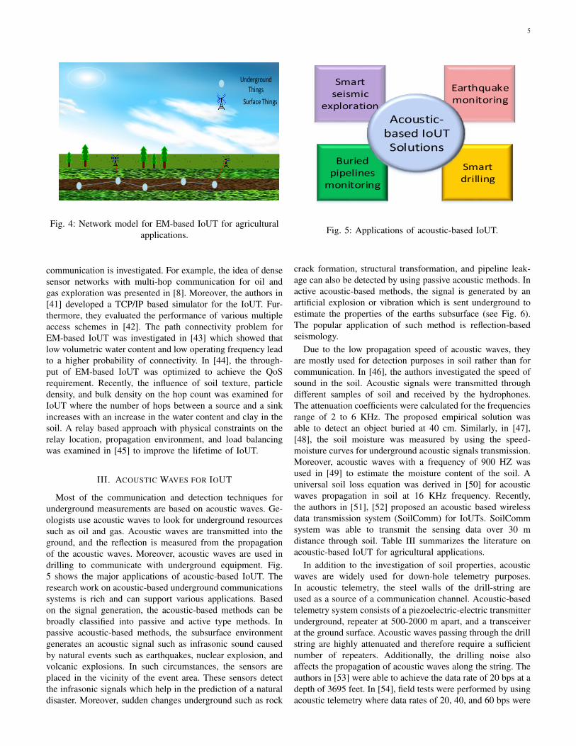
The literature on channel model for EM-based IoUT is rich.However, few works exist on the routing protocols. In thissection, we cover the existing research on networking layerprotocols for EM-based IoUT. Fig. 3 and 4 shows examplesof a multi-hop network for an EM-based oil and gas IoUT andagricultural IoUT respectively. Due to the limited transmissionrange of EM waves in the underground environment multi-hop
5
Underground Things
Surface Things
Fig. 4: Network model for EM-based IoUT for agriculturalapplications.
communication is investigated. For example, the idea of densesensor networks with multi-hop communication for oil andgas exploration was presented in [8]. Moreover, the authors in[41] developed a TCP/IP based simulator for the IoUT. Fur-thermore, they evaluated the performance of various multipleaccess schemes in [42]. The path connectivity problem forEM-based IoUT was investigated in [43] which showed thatlow volumetric water content and low operating frequency leadto a higher probability of connectivity. In [44], the through-put of EM-based IoUT was optimized to achieve the QoSrequirement. Recently, the influence of soil texture, particledensity, and bulk density on the hop count was examined forIoUT where the number of hops between a source and a sinkincreases with an increase in the water content and clay in thesoil. A relay based approach with physical constraints on therelay location, propagation environment, and load balancingwas examined in [45] to improve the lifetime of IoUT.
III. ACOUSTIC WAVES FOR IOUT
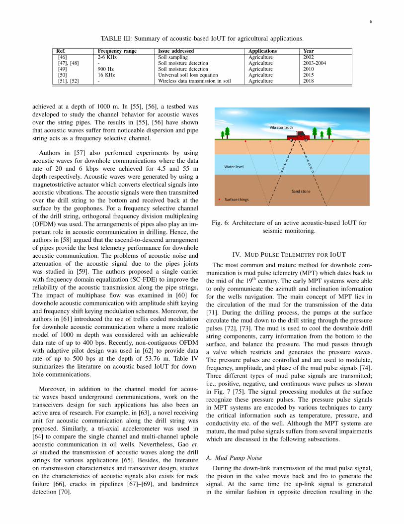
Most of the communication and detection techniques forunderground measurements are based on acoustic waves. Ge-ologists use acoustic waves to look for underground resourcessuch as oil and gas. Acoustic waves are transmitted into theground, and the reflection is measured from the propagationof the acoustic waves. Moreover, acoustic waves are used indrilling to communicate with underground equipment. Fig.5 shows the major applications of acoustic-based IoUT. Theresearch work on acoustic-based underground communicationssystems is rich and can support various applications. Basedon the signal generation, the acoustic-based methods can bebroadly classified into passive and active type methods. Inpassive acoustic-based methods, the subsurface environmentgenerates an acoustic signal such as infrasonic sound causedby natural events such as earthquakes, nuclear explosion, andvolcanic explosions. In such circumstances, the sensors areplaced in the vicinity of the event area. These sensors detectthe infrasonic signals which help in the prediction of a naturaldisaster. Moreover, sudden changes underground such as rock
Smart seismic
exploration
Smart drilling
Earthquake monitoring
Buried pipelines
monitoring
Acoustic-based IoUT Solutions
Fig. 5: Applications of acoustic-based IoUT.
crack formation, structural transformation, and pipeline leak-age can also be detected by using passive acoustic methods. Inactive acoustic-based methods, the signal is generated by anartificial explosion or vibration which is sent underground toestimate the properties of the earths subsurface (see Fig. 6).The popular application of such method is reflection-basedseismology.
Due to the low propagation speed of acoustic waves, theyare mostly used for detection purposes in soil rather than forcommunication. In [46], the authors investigated the speed ofsound in the soil. Acoustic signals were transmitted throughdifferent samples of soil and received by the hydrophones.The attenuation coefficients were calculated for the frequenciesrange of 2 to 6 KHz. The proposed empirical solution wasable to detect an object buried at 40 cm. Similarly, in [47],[48], the soil moisture was measured by using the speed-moisture curves for underground acoustic signals transmission.Moreover, acoustic waves with a frequency of 900 HZ wasused in [49] to estimate the moisture content of the soil. Auniversal soil loss equation was derived in [50] for acousticwaves propagation in soil at 16 KHz frequency. Recently,the authors in [51], [52] proposed an acoustic based wirelessdata transmission system (SoilComm) for IoUTs. SoilCommsystem was able to transmit the sensing data over 30 mdistance through soil. Table III summarizes the literature onacoustic-based IoUT for agricultural applications.
In addition to the investigation of soil properties, acousticwaves are widely used for down-hole telemetry purposes.In acoustic telemetry, the steel walls of the drill-string areused as a source of a communication channel. Acoustic-basedtelemetry system consists of a piezoelectric-electric transmitterunderground, repeater at 500-2000 m apart, and a transceiverat the ground surface. Acoustic waves passing through the drillstring are highly attenuated and therefore require a sufficientnumber of repeaters. Additionally, the drilling noise alsoaffects the propagation of acoustic waves along the string. Theauthors in [53] were able to achieve the data rate of 20 bps at adepth of 3695 feet. In [54], field tests were performed by usingacoustic telemetry where data rates of 20, 40, and 60 bps were
6
TABLE III: Summary of acoustic-based IoUT for agricultural applications.
Ref. Frequency range Issue addressed Applications Year[46] 2-6 KHz Soil sampling Agriculture 2002[47], [48] - Soil moisture detection Agriculture 2003-2004[49] 900 Hz Soil moisture detection Agriculture 2010[50] 16 KHz Universal soil loss equation Agriculture 2015[51], [52] - Wireless data transmission in soil Agriculture 2018
achieved at a depth of 1000 m. In [55], [56], a testbed wasdeveloped to study the channel behavior for acoustic wavesover the string pipes. The results in [55], [56] have shownthat acoustic waves suffer from noticeable dispersion and pipestring acts as a frequency selective channel.
Authors in [57] also performed experiments by usingacoustic waves for downhole communications where the datarate of 20 and 6 kbps were achieved for 4.5 and 55 mdepth respectively. Acoustic waves were generated by using amagnetostrictive actuator which converts electrical signals intoacoustic vibrations. The acoustic signals were then transmittedover the drill string to the bottom and received back at thesurface by the geophones. For a frequency selective channelof the drill string, orthogonal frequency division multiplexing(OFDM) was used. The arrangements of pipes also play an im-portant role in acoustic communication in drilling. Hence, theauthors in [58] argued that the ascend-to-descend arrangementof pipes provide the best telemetry performance for downholeacoustic communication. The problems of acoustic noise andattenuation of the acoustic signal due to the pipes jointswas studied in [59]. The authors proposed a single carrierwith frequency domain equalization (SC-FDE) to improve thereliability of the acoustic transmission along the pipe strings.The impact of multiphase flow was examined in [60] fordownhole acoustic communication with amplitude shift keyingand frequency shift keying modulation schemes. Moreover, theauthors in [61] introduced the use of trellis coded modulationfor downhole acoustic communication where a more realisticmodel of 1000 m depth was considered with an achievabledata rate of up to 400 bps. Recently, non-contiguous OFDMwith adaptive pilot design was used in [62] to provide datarate of up to 500 bps at the depth of 53.76 m. Table IVsummarizes the literature on acoustic-based IoUT for down-hole communications.
Moreover, in addition to the channel model for acous-tic waves based underground communications, work on thetransceivers design for such applications has also been anactive area of research. For example, in [63], a novel receivingunit for acoustic communication along the drill string wasproposed. Similarly, a tri-axial accelerometer was used in[64] to compare the single channel and multi-channel upholeacoustic communication in oil wells. Nevertheless, Gao et.al studied the transmission of acoustic waves along the drillstrings for various applications [65]. Besides, the literatureon transmission characteristics and transceiver design, studieson the characteristics of acoustic signals also exists for rockfailure [66], cracks in pipelines [67]–[69], and landminesdetection [70].
Surface things
Water level
Sand stone
Vibrator truck
Fig. 6: Architecture of an active acoustic-based IoUT forseismic monitoring.
IV. MUD PULSE TELEMETRY FOR IOUT
The most common and mature method for downhole com-munication is mud pulse telemetry (MPT) which dates back tothe mid of the 19th century. The early MPT systems were ableto only communicate the azimuth and inclination informationfor the wells navigation. The main concept of MPT lies inthe circulation of the mud for the transmission of the data[71]. During the drilling process, the pumps at the surfacecirculate the mud down to the drill string through the pressurepulses [72], [73]. The mud is used to cool the downhole drillstring components, carry information from the bottom to thesurface, and balance the pressure. The mud passes througha valve which restricts and generates the pressure waves.The pressure pulses are controlled and are used to modulate,frequency, amplitude, and phase of the mud pulse signals [74].Three different types of mud pulse signals are transmitted;i.e., positive, negative, and continuous wave pulses as shownin Fig. 7 [75]. The signal processing modules at the surfacerecognize these pressure pulses. The pressure pulse signalsin MPT systems are encoded by various techniques to carrythe critical information such as temperature, pressure, andconductivity etc. of the well. Although the MPT systems aremature, the mud pulse signals suffers from several impairmentswhich are discussed in the following subsections.
A. Mud Pump Noise
During the down-link transmission of the mud pulse signal,the piston in the valve moves back and fro to generate thesignal. At the same time the up-link signal is generatedin the similar fashion in opposite direction resulting in the

7
TABLE IV: Summary of acoustic-based IoUT for down-hole communication.
Ref. Data rate Depth Issue addressed Applications Year[53] 20 bps 1120 m Down-hole communication Underground drilling 2006[54] 20-60 bps 1000 m Field tests for down-hole com-
municationUnderground drilling 2007
[57] 6 and 20kbps
55 and 4.5 m OFDM for down-hole commu-nication
Underground drilling 2013
[59] - - Impact of pipe joints on signaltransmission
Underground drilling 2013
[60] - - Impact of multi-phase flowwith ASK and FSK
Underground drilling 2014
[61] 400 bps 1000 m Trellis coded modulation fordown-hole communication
Underground drilling 2014
[62] 500 bps 53.76 m NC-OFDM for down-holecommunication
Underground drilling 2018
(a) (b) (c)
Time
Am
pli
tud
e
Time
Am
pli
tud
e
Time
Am
pli
tud
e
Drill bit
Mu
d p
uls
er
Drilling rig
Fig. 7: Three different types of MPT systems. (a) Positivepulses from blocking/unblocking of the fluid; (b) Negativepulses by pressure in the drill string; (c) Continuous pulses
by using a rotor.
interference between the down-link and up-link signals [76].Moreover, the pressure of the pump creates noticeable amountof frequency and amplitude varaitions in the frequency rangeof 1-20 Hz. To diminish these effects, MPT systems uses twodifferent transducers at the surface receivers which are wellspaced [77], [78]. In [79] and [80], the authors have used leastmean square filtering algorithm to reduce the noise generatedby the mud pumps.
B. Attenuation and DispersionAs the mud pulse signals propagate along the borehole, the
signals are attenuated and dispersed due to under-balanceddrilling mud [81]. The major sources of attenuation are themud type, joints in the drill string, signal frequency, diameterof the string, and borehole depth [82]. Low frequency signalscan be used to avoid excessive attenuation of the mud pulsesignals [83].
C. Rock Fragments and Gas LeakageDuring the drilling process, rock particles and gas may enter
the mud used for the pressure pulses which changes the density
dij
rti rrj
Transmission coil Receiving coil
Fig. 8: MI communication link.
and compressibility of the mud [84]. These rock particles andgas reduce the transmission speed of the pressure pulse waves.Hence, it is essential to study the velocity continuity of thedrilling mud because the gas leakage into the mud can leadto unstable drilling which can cause environmental pollutionand potential loss of human lives [85].
V. MAGNETIC INDUCTION FOR IOUT
One of the major factors which limit the evolution ofIoUT is the challenging underground environment. We havepreviously discussed that the heterogamous soil medium andwater content of the soil limit the transmission range of EM-based IoUT [18]. Hence, magnetic induction (MI) has beenintroduced to overcome the limitations of EM waves for IoUT[86], [87]. In this section, we will cover multiple aspects ofMI-based IoUT which include channel modeling, networking,and localization.
A. Chanel Modeling
A time-varying magnetic field is used in MI-based IoUT forcommunication between a transmitting and a receiving node.The coil antenna of the transmitting node produces a time-varying magnetic field which induces the current at the coilantenna of the receiver. The design of a conventional MI-basedtransceiver is shown in Fig. 8 where dij is the distance betweenthe coil i and j , and rti , rrj are their radiuses respectively.The transmitting current I = I0e
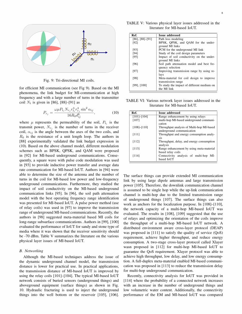
−jωt with direct current I0and angular frequency ω induces current in the nearby coil.However, if the transmitting and receiving coils are not wellcoupled, a single coil may not guarantee communication, andtherefore a tri-directional coil structure was proposed in [88]
8
n1
n2
Fig. 9: Tri-directional MI coils.
for efficient MI communication (see Fig 9). Based on the MIphenomena, the link budget for MI-communication at highfrequency and with a large number of turns in the transmittercoil Nt is given in [86], [88]–[91] as
Prj =ωµPtiNrjr
3tir
3rj sin2 αij
16R0d6ij
, (10)
where µ represents the permeability of the soil, Pti is thetransmit power, Nrj is the number of turns in the receivercoil, αij is the angle between the axes of the two coils, andR0 is the resistance of a unit length loop. The authors in[88] experimentally validated the link budget expression in(10). Based on the above channel model, different modulationschemes such as BPSK, QPSK, and QAM were proposedin [92] for MI-based underground communications. Conse-quently, a square wave with pulse code modulation was usedin [93] to provide inductive power transfer and average datarate communication for MI-based IoUT. Authors in [94] wereable to determine the size of the antenna and the number ofturns in the coil for MI-based low power and low-frequencyunderground communications. Furthermore, they studied theimpact of soil conductivity on the MI-based undergroundcommunication links [95]. In [96], the soil path attenuationmodel with the best operating frequency range identificationwas presented for MI-based IoUT. A pulse power method (useof relay coils) was used in [97] to improve the transmissionrange of underground MI-based communications. Recently, theauthors in [98] suggested meta-material based MI coils forlong-range subsurface communications. Authors in [99], [100]evaluated the performance of IoUT for sandy and stone type ofmedia where it was shown that the receiver sensitivity shouldbe -70 dBm. Table V summarizes the literature on the variousphysical layer issues of MI-based IoUT.
B. Networking
Although the MI-based techniques address the issue ofthe dynamic underground channel model, the transmissiondistance is lower for practical use. In practical applications,the transmission distance of MI-based IoUT is improved byusing the relay coils [101]–[104]. The typical MI-based IoUTnetwork consists of buried sensors (underground things) andaboveground equipment (surface things) as shown in Fig.10. Hydraulic fracturing is used to inject the undergroundthings into the well bottom or the reservoir [105], [106].
TABLE V: Various physical layer issues addressed in theliterature for MI-based IoUT.
Ref. Issue addressed[86], [88]–[91] Path loss modeling[92] BPSK, QPSK, and QAM for the under-
ground MI links[93] PCM for the underground MI link[94] Study of the coil design parameters[95] Impact of soil conductivity on the under-
ground MI links[96] Soil path attenuation model and best fre-
quency selection[97] Improving transmission range by using re-
lays[98] Meta-material for coil design to improve
transmission range[99], [100] To study the impact of different medium on
the MI link
TABLE VI: Various network layer issues addressed in theliterature for MI-based IoUT.
Ref. Issue addressed[101]–[104] Range enhancement by using relays[107] multi-hop MI-based underground communi-
cation[108]–[110] Throughput analysis of Multi-hop MI-based
underground communication[111] Throughput and energy consumption analy-
sis[112] Throughput, delay, and energy consumption
analysis[113] Range enhancement by using meta-material
based relay coils[114] Connectivity analysis of multi-hop MI-
based IoUT
The surface things can provide extended MI communicationlink by using large dipole antennas and large transmissionpower [105]. Therefore, the downlink communication channelis assumed to be single hop while the up-link communicationchannel is multi-hop due to the limited transmission rangeof underground things [107]. The surface things can alsowork as anchors for the localization purpose. In [108]–[110],the network capacity of a multi-hop MI-based IoUT wasevaluated. The results in [108], [109] suggested that the useof relays and optimizing the orientation of the coils improvethe throughput of a multi-hop MI-based IoUT network. Adistributed environment aware cross-layer protocol (DEAP)was proposed in [111] to satisfy the quality of service (QoS)requirement, achieve higher throughput, and reduce energyconsumption. A two-stage cross-layer protocol called Xlayerwasn proposed in [112] for multi-hop MI-based IoUT toguarantee the QoS requirement. Xlayer protocol was able toachieve high throughput, low delay, and low energy consump-tion. A full-duplex meta-material enabled MI-based communi-cation was proposed in [113] to reduce the transmission delayfor multi-hop underground communication.
Recently, connectivity analysis for IoUT was provided in[114] where the probability of a connected network increaseswith an increase in the number of underground things andlow volumetric water content. Additionally, the connectivityperformance of the EM and MI-based IoUT was compared

9
AnchorsUnderground things
Water level
Sand stone
Oil reservoir
Hydraulic fracturing
Fig. 10: Network model for MI-based IoUT for oil and gasreservoirs.
where the results have shown that for a given environmentaland network settings MI perform better than EM waves. TableVI presents the literature on various network layer issues forMI-based IoUT.
C. Localization
Localization is an essential task in wireless networks whichenable various location-based services. Hence, localizationtechniques for the terrestrial and underwater wireless com-munication networks are well investigated in the past. Forexample in [115] the authors reviewed various localizationtechniques for terrestrial wireless networks. Similarly, in [116]localization techniques for marine networks are studied. Thelocalization techniques can be classified based on the rang-ing technique (range-based/range-free), type of computation(centralized/distributed), and space (2D/3D). However, the lit-erature on localization techniques for the underground wirelessnetworks is limited due to various challenges such as harsh andlight-less underground environment, non-availability of globalpositioning system (GPS) signals, high attenuation, and narrowoperational area. Although efforts have been made in thepast to develop localization techniques for harsh environmentssuch as indoor and underwater, however, the undergroundenvironment does not support the use of these communicationtechnologies, and therefore the localization techniques for theindoor and marine environment cannot be directly applied tothe underground case [2].
Accordingly, a two-dimensional (2D) localization techniquewas developed by Andrew et. al in [117] by using magnetic-induction to track animals underground. Furthermore, theyextended their 2D tracking system to a three-dimensional(3D) one in [118]. Moreover, they used the 3D MI-basedtracking model for underground rescue operations [119]. Asthe propagation of MI signals is highly affected by the soilmedium, therefore, the impact of minerals and rocks on thelocalization accuracy was studied in [120]. It was observedin [120] that the skin effect of the underground medium
10 15 20 25 3010-3
10-2
10-1
100
101
102
CR
LB (
m)
Fig. 11: CRLB vs. Number of turns in the receiver.
0.01 0.015 0.02 0.025 0.03 0.035 0.04
Coil size (m)
10-6
10-4
10-2
100
102
CR
LB (
m)
Fig. 12: CRLB vs. Coil size.
is almost negligible at very low frequencies whereas thelocalization accuracy depends on the attenuation properties ofvarious underground materials. Recently, simulated annealingwasn used for MI-based terrestrial and underground wirelessnetworks in [121], [122] which can achieve sub-meter levelaccuracy.
Furthermore, a modified semidefinite programming-basedrelaxation technique was used in [123] to determine theposition of the underground sensors. A single anchor was usedin [124] to find the location of all other underground sensorsin 3D for MI-based IoUT. Trilateration, machine learning, andhybrid passive localization techniques were used in [125] toestimate the position of a target node in 2D MI-based IoUT.Recently, an analytical model has been presented in [126] fordistance estimation in MI-based IoUT. However, none of theabove works analyze the achievable accuracy of localizationfor MI-based 3D IoUT which is an important and challengingtask. The achievable accuracy of localization techniques ischaracterized by estimation bounds such as the Cramer Raolower bound (CRLB). In the past, CRLB have been derivedfor various wireless networks such as internet of things (IoT)[127], vehicular ad-hoc networks [128], source localization[129], radar tracking [130], cognitive radio networks [131]–[133], and underwater wireless networks [134]–[136]. TheCRLB analysis mainly depends on the ranging technique andnetwork parameters such as the number of anchors, networktype (multi-hop or single hop), the density of the network, and

10
20 20.5 21 21.5 22 22.5 2310-4
10-3
10-2
10-1
CR
LB (
m)
Fig. 13: CRLB vs. Transmit power.
transmission range [137], [138]. These findings have led to thedevelopment of robust and accurate localization algorithms.Hence CRLB analysis is an attractive tool for localization sys-tems due to its simplicity and generic expressions. Therefore,in [139], we derived the expression of the CRLB for the MI-based IoUT localization. The derived bound in [139] takesinto account the channel and network parameters of MI-basedIoUT.
Consequently, we used the simulation parameters from[123] to investigate the impact of various channel and networkparameters on the CRLB. Fig. 11 shows the impact of thenumber of turns in the MI coil and the noise variance on theachievable accuracy. The values of the noise variance are keptas 0.05, 0.3, and 0.7 m respectively whereas the frequencyis 13 MHz. Fig. 11 suggests that to get better localizationaccuracy more number of turns in the coil are requiredhowever increasing the number of turns may increase thesize of the coil. However, the harsh underground environmentrequires a small size of the MI coil. Hence, the impact of coilsize is examined in Fig. 12 which suggests that increasing thesize of the coil improve the accuracy. Thus, there is a trade-off between the size of the coil and the localization accuracywhich should be taken into account before the deployment.
Moreover, we have also tested the impact of transmissionpower on the achievable localization accuracy in Fig. 13.Commercially available MI coil have transmission power inthe range of 100 200 mW (20-23 dBm). Thus we kept thetransmit power in the range of 20-23 dBm with the variablesize of the coils. Fig. 13 shows that with the increase in trans-mit power the achievable accuracy improves. Accordingly,the above results suggest that the achievable accuracy of anylocalization algorithm for MI-based IoUT is the function ofthe number of turns in the MI coil, noise variance, size of thecoil, transmit power, frequency, and the number of anchors.Therefore, all these parameters are important to design a robustand accurate localization technique for IoUT.
D. Charging of the MI Coils
Lifetime is an important parameter for IoUT due to theharsh underground environment. Therefore, research effortshave been made to improve the lifetime of the IoUT [140]. Acharging method for IoUT has been proposed in [140] where avirtual magnetic relay network and optimized routing protocol
Cable
FGB sensor
Surface equipment
Fig. 14: Fiber optic monitoring system for IoUT.
was used to reduce the energy consumption. However, thecharging efficiency of the proposed system in [140] remainsvery low for even moderate size of coils. Consequently, in[141] an optimized energy model framework was proposed forlinear topology. The problem of charging underground coils isstill open research problem and other options such as energyharvesting can be investigated.
VI. WIRED COMMUNICATIONS FOR IOUT
Wireless communication channels reduce the complexityand cost of underground monitoring. However, existing wire-less technologies fail to provide timely, reliable and accuratesolutions, especially for the deep underground monitoring.Hence, wired technologies such as coaxial cable and opticalfiber are used for down-hole monitoring [142]–[146]. Sincefor higher data rates, optical fiber has replaced co-axial basedwired communication. In this section, we cover the literatureon optical fiber-based communication systems for undergroundapplications.
Fiber optic sensing technologies have been applied toseveral commercial and industrial application in the pasttwo decades. These sensing technologies can provide bothsensing and information transfer in the harsh environment.Due to these attributes, they are well suited for the harshenvironment in oil and gas reservoirs [147]. The fiber opticbased underground sensing system consists of fiber Bragggrating (FBG) sensors which are connected to the optical fibercable with the help of ultraviolet photo-inscription method[148] (see Fig. 14). The authors in [149] proposed an FBGbased real-time temperature and fluid monitoring system of oilbore-holes. In [150], Yan et. al designed FBG based seismic

11
LEDs
Fig. 15: VLC based IoUT for gas pipelines.
geophone for oilfield exploration which has shown bettersensitivity than the conventional geophones for 10-70 Hz rangeof frequencies. Wavelength division multiplexing was used tocombine the information from two fiber onto a single fiber in[151] for the temperature and pressure sensing in a well-bore.Recently, the authors in [152] installed an optical fiber-baseddown-hole monitoring system at the shoreline of Marmarasea in Turkey to provide geophysical observations. In short,optical fiber based underground monitoring systems providehigh-speed communication and are immune to electromagneticinterference which mainly depends on the development of fibergrating sensors [153].
VII. VISIBLE LIGHT COMMUNICATIONS FOR IOUT
Light cannot pass through soil therefore visible light com-munication (VLC) can only be used for down-hole monitoringin gas fields. To the best of the author’s knowledge, the onlyVLC-based down-hole monitoring systems were proposed in[154], [155]. In [154], light emitting diodes (LEDs) were usedat the bottom of the pipeline, and a single photon avalanchediode (SPAD) was used as a receiver at the surface (see Fig.15). The proposed system in [154] was able to achieve the datarate of 1-5 Kbps for the depth of 4000 m. However, the authorsin [154] assume empty pipeline which is not realistic. Hence,in [155] the authors provided a channel model for VLC-basedunderground gas pipelines in the presence of methane gas.Different pulse amplitude modulation (PAM) schemes weretested, and the results have shown that for a target BER of10−6, 8-PAM can reach the target distance of 22 m. Similarly,higher order PAM provides a better data rate but reducedtransmission range with a minimum of 3.82 m for 512-PAM.Nevertheless, the research on VLC-based IoUT is in its infancyand need to be examined in the future.
VIII. FUTURE RESEARCH CHALLENGES
The recent advances in IoUT have broadened the scope ofthis research area. Hence, in this section, we provide variousnew challenges for the IoUT. Table VII presents the signifi-cance of each research challenge for a specific undergroundapplication.
A. Deployment
The deployment of smart objects for IoUT in the harsh un-derground environment is a challenging issue [2]. Installationand management of smart objects underground are much moredifficult compared to the terrestrial networks. Moreover, the
TABLE VII: Significance of each research challenge forvarious applications.
Research Challenge Agriculture Seismicexploration
Oil &Gas
Deployment Medium High HighChannel modeling Medium Medium HighTransmission range Low High MediumLatency Low Low MediumReliability Low Medium HighSecurity Medium High HighScalability Low Medium MediumRobustness Low Medium HighNetworking High Medium MediumCloud computing High Medium LowFog computing Low Medium HighLocalization Medium High Medium
underground objects can be easily damaged during the diggingprocess. Hence, efficient deployment of the smart objects isrequired to minimize the installation cost of the IoUT. Forexample, a smart object with high energy requirement shouldbe deployed near the surface for ease of management as thereplacement of batteries in the underground environment ischallenging. Moreover, to avoid the replacement of batteries,a battery with high capacity should be used, and power savingprotocols should be applied. Unfortunately, the research workon the efficient deployment of IoUT is limited, which takesinto account the various system and network parameters suchas deployment depth, number of smart objects, lifetime, androuting.
B. Channel Modeling
In terrestrial communications, the strength of the EM signaldecays with the square of the distance while in the soil, thedecay is much faster due to attenuation from the soil medium[18]. The major loss factors for a given frequency in the soilare the permittivity and conductivity of the type of soil. Hence,MI-based communication has been introduced for the IoUTwhich is based on magnetic field propagation [88]. Althoughthe path loss for each type of communication channel hasbeen extensively analyzed in the past, unfortunately, fewefforts have been made to provide a fully functional MI-basedIoUT with practical signal transmission schemes to verify thechannel models. Nevertheless, the demanding applications ofthe underground stimulate the research in this direction.

12
C. Limited Transmission RangeThe MI technology has certain advantages such as prone to
multi-path fading and boundary effects which makes it idealfor the communication and localization in the undergroundenvironment [88]. However, MI technology also has somedisadvantages; the most significant one is the limited trans-mission range due to high path loss in the soil. Although infew works large coils with high transmission power was usedfor the long-range downlink communication and localization[123], however, it may not be a practical solution. Hence, thelimited transmission range of buried smart objects in IoUT isa significant issue which is still an open research problem.
D. Low Latency and Reliable CommunicationsMost of the applications of IoUT require low latency and
reliable communication. For example, the underground thingsare deployed in the oil and gas wells to perform critical sensingtasks such as temperature/pressure, pipe leaks and gas leaks,and therefore the data should be reliable and receive at thesurface with low latency. If the sensed data from even asingle sensor is not received on time, it can lead to a disaster.As the performance of the IoUT is highly susceptible to theharsh underground environment, it can lead to unreliable andhigh latency communication. Hence, a reliable and low latencyarchitecture is required for IoUT which can count for sensorfailures and minimize the transmission delay.
E. SecurityAlthough efforts have been made in the past to model the
channel for IoUT [18], [88], unfortunately, security for IoUTdid not get much attention from the research community.Security of IoUT includes the security of equipment andthe communication protocols. Various attacks such as nodereplication, signal jamming, and wormhole can be launched todestabilize the operation of the IoUT. The security breach canalso exhaust the network resources by triggering false alarmsand responding to the false alarms. Therefore, security is ofutmost importance for the stable IoUT and needs the attentionof the researchers.
F. ScalabilityRouting overhead, higher network density, and node failures
can cause scalability issue for IoUT. Moreover, the highenergy consumption and limited memory of undergroundsensor nodes limit the scalability of the network. Additionally,the IoUT system may consist of sensor nodes developed bydifferent vendors which can lead to interoperability issues.Hence, IoUT requires the development of self-healing and self-organizing techniques to overcome the scalability issue.
G. RobustnessRobustness is another crucial issue for IoUT which has
not been addressed in the past. In an underground resource-constrained environment where there are various challengessuch as dynamic topology, an energy constraint, and sparsenodes, robustness is critical. Additionally, the localizationtechniques developed for IoUT should be robust to the noisesince it can lead to large localization error.
H. Hybrid SensingA hybrid sensing system for IoUT integrates signals from
multiple types of sensor systems for the detection and lo-calization of an event. For example, a network of long-termunderground fiber sensors can be fused with short-term groundpenetrating radars for the detection and localization of anunderground event. Hence, the hybrid sensing technologiesand new concepts, such as crowd-sensing can proactivelydetect and localize underground events.
I. Software Defined NetworkingAlthough the research on IoUT is still in its infancy, re-
searchers are already looking to develop networking solutionsfor the smart objects connected underground. Software-definednetworking (SDN) seems to be rather appropriate networkingsolution for the IoUT [156]. By employing SDN for theIoUT reduces the network complexity, improve load balancing,provide congestion control, efficiently utilize the network re-sources, improve the network lifetime, and reduce the latency.Hence with all these advantages, the SDN paradigm needs tobe examined for the IoUT.
J. Big DataIoUT is going to generate a large amount of exploration data
which include data coming from various applications such asagriculture, seismic surveying, and oil/gas fields. Hence thislarge of data need to be organized for a proper analysis, ametric calculation, or an event correlation to make accuratedecisions [157]. Therefore, proper data analytics tools need tobe developed to support the large amount of data produced inIoUT.
K. Cloud and Fog ComputingThe real-time and localized operations can be enabled
for IoUT by integrating it with cloud and fog computing.Moreover, cloud/fog computing can provide various servicesfor IoUT such as scalability, location awareness, low latency,and mobility. In the recent past cloud computing has beenused to provide maintenance for the oil and gas industrieswhile fog computing has been used to reduce the data trafficand provide the analysis of the data at the network edge [158].For example, in time-critical applications by the time the datareach to the cloud for analysis the opportunity to make adecision might be gone. Hence, fog computing techniquesshould be integrated with the IoUT to support the in-timedecision.
L. Robust and Accurate Localization MethodsLocalization for IoUT enables numerous applications such
as geo-tagged sensing data, monitoring of the undergroundenvironment, and optimized fracturing. Few efforts have beenmade in the past to find the location of buried undergroundobjects for MI-based IoUT [118], [120], [121], [123], [139].However, localization techniques for IoUT systems based onthe EM and acoustic waves do not exist. Therefore, robust andaccurate three-dimensional methods need to be developed toenable the applications as mentioned earlier.

13
IX. SUMMARY AND CONCLUSIONS
In this article, we have surveyed various communication,networking, and localization techniques for the internet ofunderground things (IoUT). In section II, we have presentedthe literature on EM waves-based IoUT where we havebriefly discussed the channel model and networking solutions.The primary applications of EM waves based IoUT are inagriculture due to their low penetration depth in the soil.In section III, acoustic waves-based solutions are presentedfor underground communications. Due to their low frequency,acoustic waves are mostly used for seismic exploration anddown-hole communication during drilling. We have gatheredthe acoustic-based underground communication techniques inTable III and IV, where we have briefly stated their applica-tions. Nevertheless, in section IV we have presented a well-known mud pulse telemetry system which is commerciallyused for down-hole communication but suffers from variousimpediments such as attenuation, dispersion, mud pump noise,and gas leakage. Furthermore, the most recent technologyfor IoUT, i.e., magnetic induction is presented in section Vand various issues addressed in literature are stated in TableV and VI. Moreover, high speed wired solutions such ascoaxial cable and optical fiber for the IoUT are presentedin section VI. In section VIII, visible light communication-based IoUT are briefly discussed which did not get muchattention of the researchers yet. Finally, we have presentedvarious future research challenges which can be investigatedby the researchers. In short, the research on communication,networking, and localization for IoUT still have a long way togo and require the attention of both academia and industry.
REFERENCES
[1] M. C. Vuran, A. Salam, R. Wong, and S. Irmak, “Internet of under-ground things in precision agriculture: Architecture and technologyaspects,” Ad Hoc Networks, vol. 81, pp. 160 – 173, 2018.
[2] S. Kisseleff, I. F. Akyildiz, and W. H. Gerstacker, “Survey on advancesin magnetic induction based wireless underground sensor networks,”IEEE Internet of Things J., pp. 1–18, Sep. 2018.
[3] M. Y. Aalsalem, W. Z. Khan, W. Gharibi, M. K. Khan, and Q. Arshad,“Wireless sensor networks in oil and gas industry: Recent advances,taxonomy, requirements, and open challenges,” J. of Network andComputer Applications, vol. 113, pp. 87 – 97, 2018.
[4] X. Dong, M. C. Vuran, and S. Irmak, “Autonomous precision agricul-ture through integration of wireless underground sensor networks withcenter pivot irrigation systems,” Ad Hoc Networks, vol. 11, no. 7, pp.1975 – 1987, 2013.
[5] X. Yu, W. Han, and Z. Zhang, “Path loss estimation for wirelessunderground sensor network in agricultural application,” AgriculturalResearch, vol. 6, no. 1, pp. 97–102, Mar 2017.
[6] F. Liedmann and C. Wietfeld, “SoMoS-A multidimensional radio fieldbased soil moisture sensing system,” in IEEE Sensors, Oct. 2017, pp.1–3.
[7] F. Liedmann, C. Holewa, and C. Wietfeld, “The radio field as a sensor-A segmentation based soil moisture sensing approach,” in IEEE SensorsApplications Symposium (SAS), Mar. 2018, pp. 1–6.
[8] S. Savazzi, U. Spagnolini, L. Goratti, D. Molteni, M. Latva-Aho,and M. Nicoli, “Ultra-wide band sensor networks in oil and gasexplorations,” IEEE Commun. Mag., vol. 51, no. 4, pp. 150–160, 2013.
[9] N. G. Franconi, A. P. Bunger, E. Sejdi, and M. H. Mickle, “Wirelesscommunication in oil and gas wells,” Energy Techno., vol. 2, no. 12,pp. 996–1005, 2014.
[10] M. Akkas, R. Sokullu, and A. Balci, “Wireless sensor networks in oilpipeline systems using electromagnetic waves,” in 9th Int. Conf. onElectrical and Electronics Engineering, 2016, pp. 143–147.
[11] R. Karli, A. Bouchalkha, and K. Alhammadi, “Investigation of elec-tromagnetic (EM) wave attenuation in oil pipeline,” in Int. Conf. onElectrical and Comput. Techno. and Apps., (ICECTA), Nov. 2017, pp.1–4.
[12] J. Wait and J. Fuller, “On radio propagation through earth,” IEEE Trans.on Antennas and Propag., vol. 19, no. 6, pp. 796–798, Nov. 1971.
[13] K. Sivaprasad and K. C. Stotz, “Reflection of electromagnetic pulsesfrom a multilayered medium,” IEEE Trans. on Geoscience Electronics,vol. 11, no. 3, pp. 161–164, Jul. 1973.
[14] R. J. Lytle, “Measurement of earth medium electrical characteristics:Techniques, Results, and Applications,” IEEE Trans. on GeoscienceElectronics, vol. 12, no. 3, pp. 81–101, Jul. 1974.
[15] R. J. Lytle and D. L. Lager, “The Yosemite experiments: HF propa-gation through rock,” Radio Science, vol. 11, no. 4, pp. 245–252, Apr.1976.
[16] W. Harrison, R. Mazza, L. Rubin, A. Yost et al., “Air-drilling,electromagnetic, MWD system development,” in SPE/IADC DrillingConference, 1990.
[17] Z. Zheng and S. Hu, “Research challenges involving cross-layeredcommunication protocol design for underground WSNS,” in 20082nd International Conference on Anti-counterfeiting, Security andIdentification, Aug. 2008, pp. 120–123.
[18] A. R. Silva and M. C. Vuran, “Empirical evaluation of wirelessunderground-to-underground communication in wireless undergroundsensor networks,” in Distributed Computing in Sensor Systems, B. Kr-ishnamachari, S. Suri, W. Heinzelman, and U. Mitra, Eds., 2009, pp.231–244.
[19] M. C. Vuran and I. F. Akyildiz, “Channel model and analysis for wire-less underground sensor networks in soil medium,” Physical Commun.,vol. 3, no. 4, pp. 245 – 254, 2010.
[20] A. R. Silva and M. C. Vuran, “Development of a testbed for wirelessunderground sensor networks,” EURASIP J. on Wireless Commun. andNetworking, vol. 2010, no. 1, pp. 62–74, Jan 2010.
[21] M. Akkas, I. Akyildiz, and R. Sokullu, “Terahertz channel modelingof underground sensor networks in oil reservoirs,” in IEEE GlobalTelecommun. Conf., 2012, pp. 543–548.
[22] S.-U. Yoon, E. Ghazanfari, L. Cheng, S. Pamukcu, and M. T. Suleiman,“Subsurface event detection and classification using wireless signalnetworks,” Sensors, vol. 12, no. 11, pp. 14 862–14 886, 2012.
[23] S. Yoon, L. Cheng, E. Ghazanfari, Z. Wang, X. Zhang, S. Pamukcu,and M. T. Suleiman, “Subsurface monitoring using low frequencywireless signal networks,” in IEEE Int. Conf. on Pervasive Comput.and Commun. Works., Mar. 2012, pp. 443–446.
[24] E. Ghazanfari, S. Pamukcu, S.-U. Yoon, M. T. Suleiman, and L. Cheng,“Geotechnical sensing using electromagnetic attenuation between radiotransceivers,” Smart Materials and Structures, vol. 21, no. 12, pp. 1–17,2012.
[25] S. Jiang, S. V. Georgakopoulos, and O. Jonah, “RF power harvestingfor underground sensors,” in Proc. of the IEEE Int. Symp. on Antennasand Propagation, Jul. 2012, pp. 1–2.
[26] R. Goyal, R. Kennedy, B. Kelsey, M. Whelan, and K. Janoyan, “Under-ground wireless sensor networks using 2nd generation RF transceivers,”in Geotechnical Special Publication, no. 234, 2014, pp. 2619–2629.
[27] X. Yu, W. Han, P. Wu, and Z. Zhang, “Experiment of propagationcharacteristics based on different frequency channels of wireless un-derground sensor network in soil,” Trans. of the Chinese Soc. forAgricultural Machinery, vol. 46, no. 4, pp. 252–260 and 218, 2015.
[28] G. Horvat, D. Vinko, and J. Vlaovic, “Impact of propagation mediumon link quality for underwater and underground sensors,” in Int.Convention on Information and Commun. Techno., Electronics andMicroelectronics (MIPRO), May 2016, pp. 129–134.
[29] A. Salam and M. C. Vuran, “Impacts of soil type and moisture onthe capacity of multi-carrier modulation in internet of undergroundthings,” in Int. Conf. on Computer Commun. and Networks, (ICCCN),Aug. 2016, pp. 1–9.
[30] S. Suherman, A. Rambe, and A. Tanjung, “Underground radio propa-gation on frequency band 97 MHz - 130 MHz,” Int. J. of Engineeringand Techno., vol. 7, no. 3, pp. 722–726, 2018.
[31] W. Daily, “A new method for characterization of downhole antennasused in geophysical probing,” Geophysical Research Letters, vol. 9,no. 5, pp. 507–509, 1982.
[32] J. Schnitger and J. D. Macpherson, “Signal attenuation for electro-magnetic telemetry systems,” in SPE/IADC Drilling Conference andExhibition, 2009, pp. 1–5.
[33] N. R. Peplinski, F. T. Ulaby, and M. C. Dobson, “Dielectric propertiesof soils in the 0.3-1.3-GHz range,” IEEE Trans. Geosci. Remote Sens.,vol. 33, no. 3, pp. 803–807, May 1995.

14
[34] M. T. Hallikainen, F. T. Ulaby, M. C. Dobson, M. A. El-rayes, andL. Wu, “Microwave dielectric behavior of wet soil-part 1: Empiricalmodels and experimental observations,” IEEE Trans. Geosci. RemoteSens., vol. 23, no. 1, pp. 25–34, Jan. 1985.
[35] S. Yoon, L. Cheng, E. Ghazanfari, S. Pamukcu, and M. T. Suleiman, “Aradio propagation model for wireless underground sensor networks,” inIEEE Global Telecommun. Conf., Dec. 2011, pp. 1–5.
[36] H. Koike and Y. Kamiya, “A new approach for subsurface wirelesssensor networks,” in Intelligent Interactive Multimedia Systems andServices 2016, G. D. Pietro, L. Gallo, R. J. Howlett, and L. C. Jain,Eds. Cham: Springer International Publishing, 2016, pp. 201–211.
[37] A. Salam and M. C. Vuran, “Wireless underground channel diversityreception with multiple antennas for internet of underground things,”in IEEE Int. Conf. on Commun., (ICC), May 2017, pp. 1–7.
[38] A. Salam, M. C. Vuran, and S. Irmak, “Di-Sense: In situ real-time permittivity estimation and soil moisture sensing using wirelessunderground communications,” Computer Networks, 2019.
[39] H. Zemmour, G. Baudoin, and A. Diet, “Soil effects on theunderground-to-aboveground communication link in ultra widebandwireless underground sensor networks,” IEEE Antennas and WirelessPropag. Lett., vol. 16, pp. 218–221, May 2017.
[40] D. Du, H. Zhang, J. Yang, and P. Yang, “Propagation characteristicsof the underground-to-aboveground communication link about 2.4GHzand 433MHz radio wave: An empirical study in the pine forest ofGuizhou province,” in IEEE Int. Conf. on Computer and Commun.,(ICCC), Dec. 2017, pp. 1041–1045.
[41] S. Conceicao, F. Ribeiro, R. Campos, and M. Ricardo, “A NS-3 basedsimulator of TCP/IP wireless underground networks,” in IFIP WirelessDays (WD), Nov. 2014, pp. 1–6.
[42] S. Conceicao, C. Pendo, A. Moreira, and M. Ricardo, “Evaluationof medium access and a positioning system in wireless undergroundsensor networks,” in Wireless Days (WD), Mar. 2016, pp. 1–6.
[43] L. T. Dung, H. T. H. Trang, S. Choi, and S. O. Hwang, “Impact of soilmedium on the path connectivity of sensors in wireless undergroundsensor networks,” in Int. Conf. on Adv. Techno. for Commun., (ATC),Oct. 2016, pp. 60–64.
[44] G. Liu, Z. Wang, and T. Jiang, “QoS-aware throughput maximizationin wireless powered underground sensor networks,” IEEE Trans. onCommun., vol. 64, no. 11, pp. 4776–4789, Nov. 2016.
[45] B. Yuan, H. Chen, and X. Yao, “Optimal relay placement for lifetimemaximization in wireless underground sensor networks,” InformationSciences, vol. 418-419, pp. 463 – 479, 2017.
[46] M. L. Oelze, W. D. OBrien, and R. G. Darmody, “Measurement ofattenuation and speed of sound in soils,” Soil Sci. Soc. Am. J., vol. 66,pp. 788–796, May 2002.
[47] F. Adamo, G. Andria, F. Attivissimo, N. Giaquinto, and M. Savino, “Anacoustic method for soil moisture measurement,” in Proc. of the 20thIEEE Instrumentation Techno. Conf., vol. 2, May 2003, pp. 952–957.
[48] F. Adamo, G. Andria, F. Attivissimo, and N. Giaquinto, “An acousticmethod for soil moisture measurement,” IEEE Trans. Instrum. Meas,vol. 53, no. 4, pp. 891–898, Aug. 2004.
[49] R. Sharma and A. Gupta, “Continuous wave acoustic method fordetermination of moisture content in agricultural soil,” Computers andelectronics in agriculture, vol. 73, no. 2, pp. 105–111, 2010.
[50] R. Freire, M. H. M. de Abreu, R. Y. Okada, P. F. Soares, and C. R.GranhenTavares, “Sound absorption coefficient in situ: An alternativefor estimating soil loss factors,” Ultrasonics sonochemistry, vol. 22,pp. 100–107, 2015.
[51] A. Singer, S. Yang, and M. Oelze, “Acoustic communications: Throughsoils, sands, water, and tissue,” The J. of the Acoustical Soc. of America,vol. 141, no. 5, pp. 3986–3987, 2017.
[52] S. Yang, O. Baltaji, Y. M. Hashash, and A. Singer, “Soilcomm: Aminiaturized through-soil wireless data transmission system,” The J. ofthe Acoustical Soc. of America, vol. 144, no. 3, pp. 1872–1872, 2018.
[53] W. R. Gardner, R. E. Hyden, E. J. Linyaev, L. Gao, C. Robbins, andJ. Moore, “Acoustic telemetry delivers more real-time downhole data inunderbalanced drilling operations,” in IADC/SPE Drilling Conf., 2006.
[54] J. M. Neff, P. L. Camwell et al., “Field test results of an acoustictelemetry MWD system,” in SPE/IADC Drilling Conference, 2007.
[55] A. K. Farraj, S. Miller, and K. Qaraqe, “Channel characterization foracoustic downhole communication systems,” in SPE Annual TechnicalConf. and Exhibition. Society of Petroleum Engineers, 2012.
[56] A. Farraj, “Acoustical communications for wireless downhole telemetrysystems,” Ph.D. dissertation, Texas A&M University, 2012.
[57] M. A. Gutierrez-Estevez, U. Krueger, K. A. Krueger, K. Manolakis,V. Jungnickel, K. Jaksch, K. Krueger, S. Mikulla, R. Giese, M. Sohmer,and M. Reich, “Acoustic broadband communications over deep drill
strings using adaptive OFDM,” in IEEE Wireless Commun. and Net-working Conf., (WCNC), Apr. 2013, pp. 4089–4094.
[58] L. S. Kumar, W. K. Han, Y. L. Guan, Y. H. Lee, and S. Sun,“Optimization of acoustic communication for industrial drilling,” inIEEE Conf. on Info. Commun. Techno., Apr. 2013, pp. 1060–1063.
[59] Z. Wei, S. Yibing, and L. Yanjun, “Design of acoustic wireless remotetransmission system for logging-while-drilling data,” in IEEE Int. Conf.on Electronic Measurement Instruments, Aug. 2013, pp. 53–57.
[60] T. J. Ahmad, M. Noui-Mehidi, and M. Arsalan, “Performance analysisof downhole acoustic communication in multiphase flow,” in 40thAnnual Conference of the IEEE Industrial Electronics Society, Oct.2014, pp. 3909–3913.
[61] K. Pelekanakis, M. Chitre, L. S. Kumar, and Y. L. Guan, “Performanceof channel coding and equalization for acoustic telemetry along drillstrings,” in IEEE Int. Conf. on Commun. Systems, Nov. 2014, pp. 610–614.
[62] D. Ma, Y. Shi, W. Zhang, and G. Liu, “Design of acoustic transmissionalong drill strings for logging while drilling data based on adaptive nc-ofdm,” AEU - Int. J. of Electronics and Commun., vol. 83, pp. 329–338,2018.
[63] Li, Zhigang, Ge, Shitong, and Fu, Zhongyao, “Design of the acousticsignal receiving unit of acoustic telemetry while drilling,” MATEC Webof Conf., vol. 61, pp. 7–12, 2016.
[64] A. Alenezi and A. Abdi, “A comparative study of multichannel andsingle channel accelerometer sensors for communication in oil wells,”in Int. Conf. on Commun. and Signal Processing (ICCSP), Apr. 2017,pp. 153–159.
[65] J. Gao, L. Chen, and Q. Li, “Study on acoustic wave transmissiontechnology of measurement-while-drilling (MWD) data,” in Int. Conf.on Adv. in Materials, Mechatronics and Civil Engineering (ICAMMCE2018), 2018, pp. 1–6.
[66] Z. Kang, Y. Yu, and C. Hou, “Study on stress and strain and character-istics of acoustic emission in the process of rock failure,” in Second Int.Conf. on Mechanic Automation and Control Engineering, Jul. 2011, pp.7737–7740.
[67] L. Sun and Y. Li, “Acoustic emission sound source localization forcrack in the pipeline,” in Chinese Control and Decision Conf., May2010, pp. 4298–4301.
[68] B. Van Hieu, S. Choi, Y. U. Kim, Y. Park, and T. Jeong, “Wirelesstransmission of acoustic emission signals for real-time monitoring ofleakage in underground pipes,” KSCE J. of Civil Engineering, vol. 15,no. 5, p. 805, May 2011.
[69] D. Su, J. V. Miro, and T. Vidal-Calleja, “Modelling in-pipe acous-tic signal propagation for condition assessment of multi-layer waterpipelines,” in IEEE 10th Conf. on Industrial Electronics and Applica-tions (ICIEA), Jun. 2015, pp. 545–550.
[70] U. S. Khan, W. Al-Nuaimy, and F. E. A. El-Samie, “Detection oflandmines and underground utilities from acoustic and gpr images witha cepstral approach,” J. of Visual Commun. and Image Representation,vol. 21, no. 7, pp. 731 – 740, 2010.
[71] P. D. Thakur, P. Agnihotri, L. Deng, A. M. Soliman, P. Kieduppatum,and W. Fernandes, “The most common impacts of drilling dynamicsand environments on log-while-drilling data: A study from Abu dhabi,”in Abu Dhabi Int. Petroleum Exhibition & Conf., 2018.
[72] R. Hutin, R. Tennent, S. Kashikar et al., “New mud pulse telemetrytechniques for deepwater applications and improved real-time datacapabilities,” in SPE/IADC drilling conference, 2001.
[73] C. Klotz, P. R. Bond, I. Wassermann, and S. Priegnitz, “A new mudpulse telemetry system for enhanced MWD/LWD applications.” inIADC/SPE Drilling Conf., Mar. 2008, pp. 1–8.
[74] D. Hahn, V. Peters, C. Rouatbi, and E. Scholz, “Reciprocating pulserfor mud pulse telemetry,” Aug. 2008, US Patent 7417920.
[75] F. Qu, Z. Zhang, J. Hu, J. Xu, S. Wang, and Y. Wu, “Adaptivedual-sensor noise cancellation method for continuous wave mud pulsetelemetry,” J. of Petroleum Sci. and Engineering, vol. 162, pp. 386 –393, 2018.
[76] Z. Jianhui, W. Liyan, L. Fan, and L. Yanlei, “An effective approachfor the noise removal of mud pulse telemetry system,” in Int. Conf. onElectronic Measurement and Instruments, Aug. 2007, pp. 1–9.
[77] I. Wasserman, D. Hahn, D. H. Nguyen, H. Reckmann, and J. Macpher-son, “Mud-pulse telemetry sees step-change improvement with oscil-lating shear valves,” Oil and Gas J., vol. 106, no. 24, pp. 39–39, 2008.
[78] I. Wassermann and A. Kaniappan., “How high-speed telemetry affectsthe drilling process,” J. of Petroleum Technology, Jun. 2009.
[79] H. Reckmann, “Downhole noise cancellation in mud-pulse telemetry,”Aug. 2014, US Patent 8811118.

15
[80] A. Jarrot, A. Gelman, and J. Kusuma, “Wireless digital communicationtechnologies for drilling: Communication in the bits/s regime,” IEEESignal Process. Mag., vol. 35, no. 2, pp. 112–120, 2018.
[81] J. Harrell, A. G. Brooks, and H. S. Morsy, “Method and apparatus formud pulse telemetry in underbalanced drilling systems,” Aug. 2000,US Patent 6097310.
[82] Y. Lin, X. Kong, Y. Qiu, and Q. Yuan, “Calculation analysis of pressurewave velocity in gas and drilling mud two-phase fluid in annulus duringdrilling operations,” Mathematical Problems in Engineering, vol. 2013,2013.
[83] R. Hutin, “Zero sum pressure drop mud telemetry modulator,” Jan.2016, US Patent 9228432.
[84] Y. Lu, J. Tang, Z. Ge, B. Xia, and Y. Liu, “Hard rock drilling techniquewith abrasive water jet assistance,” Int. J. of Rock Mechanics andMining Sciences, vol. 60, pp. 47–56, 2013.
[85] S. M. Mwachaka, A. Wu, and Q. Fu, “A review of mud pulse telemetrysignal impairments modeling and suppression methods,” J. of PetroleumExploration and Production Techno., Jun 2018.
[86] Z. Sun and I. F. Akyildiz, “Underground wireless communication usingmagnetic induction,” in IEEE Int. Conf. on Commun., Jun. 2009, pp.1–5.
[87] C. M. Caffrey, J. Hakli, M. Hirvonen, I. Huhtinen, K. Nummila,and T. Lehikoinen, “Magnetically coupled wireless communicationfor buried environmental sensor,” in Int. Conf. on Environment andElectrical Engineering, May 2013, pp. 341–345.
[88] X. Tan, Z. Sun, and I. F. Akyildiz, “Wireless underground sensornetworks: Mi-based communication systems for underground applica-tions.” IEEE Antennas and Propag. Mag., vol. 57, no. 4, pp. 74–87,Aug. 2015.
[89] I. F. Akyildiz and E. P. Stuntebeck, “Wireless underground sensornetworks: Research challenges,” Ad Hoc Networks, vol. 4, no. 6, pp.669 – 686, Nov. 2006.
[90] Z. Sun and I. F. Akyildiz, “Magnetic induction communications forwireless underground sensor networks,” IEEE Trans. Antennas Propag,vol. 58, no. 7, pp. 2426–2435, Jul. 2010.
[91] L. Yan, D. Wei, M. Pan, and J. Chen, “Downhole wireless communi-cation using magnetic induction technique,” in United States NationalCommittee of URSI National Radio Science Meeting (USNC-URSINRSM), Jan. 2018, pp. 1–5.
[92] S. Kisseleff, I. F. Akyildiz, and W. Gerstacker, “On modulation formagnetic induction based transmission in wireless underground sensornetworks,” in IEEE Int. Conf. on Commun., (ICC), Jun. 2014, pp. 71–76.
[93] A. Gungi, V. Vippalapalli, K. A. Unnikrishna Menon, and B. Hariharan,“Inductively powered underground wireless communication system,”in Microelectronics, Electromagnetics and Telecommunications, S. C.Satapathy, N. B. Rao, S. S. Kumar, C. D. Raj, V. M. Rao, and G. V. K.Sarma, Eds., 2016, pp. 205–215.
[94] J. Ma, X. Zhang, and Q. Huang, “Near-field magnetic induction com-munication device for underground wireless communication networks,”Science China Information Sciences, vol. 57, no. 12, pp. 1–11, 2014.
[95] J. Ma, X. Zhang, Q. Huang, L. Cheng, and M. Lu, “Experimental studyon the impact of soil conductivity on underground magneto-inductivechannel,” IEEE Antennas Wireless Propag. Lett., vol. 14, pp. 1782–1785, Apr. 2015.
[96] A. R. Silva and M. Moghaddam, “Design and implementation of low-power and mid-range magnetic-induction-based wireless undergroundsensor networks,” IEEE Trans. Instrum. Meas., vol. 65, no. 4, pp. 821–835, Apr. 2016.
[97] A. M. Zungeru, H. Ezea, and J. Katende, “Pulsed power systemfor wireless underground sensor networks,” in Third Int. Conf. onElectrical, Electronics, Computer Engineering and their Applications(EECEA), Apr. 2016, pp. 126–132.
[98] H. Guo, Z. Sun, and C. Zhou, “Practical design and implementationof metamaterial-enhanced magnetic induction communication,” IEEEAccess, vol. 5, pp. 17 213–17 229, 2017.
[99] C. H. Martins, A. A. Alshehri, and I. F. Akyildiz, “Novel MI-based(FracBot) sensor hardware design for monitoring hydraulic fracturesand oil reservoirs,” in IEEE 8th Annual Ubiquitous Computing, Elec-tronics and Mobile Commun. Conf., (UEMCON), Oct. 2017, pp. 434–441.
[100] A. A. Alshehri, C. H. Martins, and I. F. Akyildiz, “Wireless FracBot(sensor) nodes: Performance evaluation of inductively coupled nearfield communication (NFC),” in IEEE Sensors Applications Symposium(SAS), Mar. 2018, pp. 1–6.
[101] Z. Sun and I. F. Akyildiz, “Optimal deployment for magnetic induction-based wireless networks in challenged environments,” IEEE Trans.Wireless Commun., vol. 12, no. 3, pp. 996–1005, Mar. 2013.
[102] A. Kulkarni, V. Kumar, and S. B. Dhok, “Enabling technologies forrange enhancement of MI based wireless non-conventional media com-munication,” in Int. Conf. on Computing, Commun. and NetworkingTechno., (ICCCNT), Jul. 2018, pp. 1–7.
[103] S. Swathi and S. Santhanam, “An efficient MI waveguide basedunderground wireless communication for smart irrigation,” in IEEEIndia Council Int. Conf., (INDICON), 2018.
[104] V. Pathak, V. Kumar, and R. K. Barik, “Magnetic induction com-munication based transceiver coil and waveguide structure modelingfor non-conventional WSNs,” in Int. Conf. on Comput., Commun. andNetworking Techno., (ICCCNT), Jul. 2018, pp. 1–7.
[105] H. Guo and Z. Sun, “Channel and energy modeling for self-containedwireless sensor networks in oil reservoirs,” IEEE Trans. WirelessCommun., vol. 13, no. 4, pp. 2258–2269, Apr. 2014.
[106] M. A. Akkas, “Channel modeling of wireless sensor networks in oil,”Wireless Personal Commun., vol. 95, no. 4, pp. 4337–4355, Aug. 2017.
[107] Z. Sun and B. Zhu, “Channel and energy analysis on magneticinduction-based wireless sensor networks in oil reservoirs,” in IEEEInt. Conf. on Commun., (ICC), Jun. 2013, pp. 1748–1752.
[108] S. Kisseleff, I. F. Akyildiz, and W. Gerstacker, “Interference po-larization in magnetic induction based wireless underground sensornetworks,” in IEEE Int. Symposium on Personal, Indoor and MobileRadio Commun., (PIMRC Workshops), Sep. 2013, pp. 71–75.
[109] S. Kisseleff, W. Gerstacker, Z. Sun, and I. F. Akyildiz, “On the through-put of wireless underground sensor networks using magneto-inductivewaveguides,” in IEEE Global Commun. Conf., (GLOBECOM), Dec2013, pp. 322–328.
[110] S. Kisseleff, I. F. Akyildiz, and W. H. Gerstacker, “Digital signaltransmission in magnetic induction based wireless underground sensornetworks,” IEEE Trans. on Commun., vol. 63, no. 6, pp. 2300–2311,Jun. 2015.
[111] S. Lin, I. F. Akyildiz, P. Wang, and Z. Sun, “Distributed cross-layerprotocol design for magnetic induction communication in wirelessunderground sensor networks,” IEEE Trans. on Wireless Commun.,vol. 14, no. 7, pp. 4006–4019, Jul. 2015.
[112] S.-C. Lin, I. F. Akyildiz, P. Wang, and Z. Sun, “Optimal energy-throughput efficiency for magneto-inductive underground sensor net-works,” in IEEE Int. Black Sea Conf. on Commun. and Networking(BlackSeaCom), May 2014, pp. 22–27.
[113] H. Guo and Z. Sun, “Full-duplex metamaterial-enabled magnetic induc-tion networks in extreme environments,” in IEEE Conf. on ComputerCommun., (INFOCOM), Apr. 2018, pp. 558–566.
[114] H. Trang, L. Dung, and S. Hwang, “Connectivity analysis of under-ground sensors in wireless underground sensor networks,” Ad HocNetworks, vol. 71, pp. 104–116, 2018.
[115] A. K. Paul and T. Sato, “Localization in wireless sensor networks:A survey on algorithms, measurement techniques, applications andchallenges,” J. of Sensor and Actuator Networks, vol. 6, no. 4, pp.1–24, 2017.
[116] N. Saeed, A. Celik, T. Y. Al-Naffouri, and M.-S. Alouini, “Underwateroptical wireless communications, networking, and localization: Asurvey,” CoRR, vol. abs/1803.02442, 2018. [Online]. Available:http://arxiv.org/abs/1803.02442
[117] A. Markham, N. Trigoni, S. A. Ellwood, and D. W. Macdonald,“Revealing the hidden lives of underground animals using magneto-inductive tracking,” in Proc. of the 8th ACM Conf. on EmbeddedNetworked Sensor Systems, 2010, pp. 281–294.
[118] A. Markham, N. Trigoni, D. W. Macdonald, and S. A. Ellwood,“Underground localization in 3-D using magneto-inductive tracking,”IEEE Sensors J., vol. 12, no. 6, pp. 1809–1816, Jun. 2012.
[119] A. Markham and N. Trigoni, “Magneto-Inductive NEtworked Res-cue System (MINERS): Taking sensor networks underground,” inACM/IEEE 11th Int. Conf. on Information Processing in Sensor Net-works (IPSN), April 2012, pp. 1–11.
[120] T. E. Abrudan, O. Kypris, N. Trigoni, and A. Markham, “Impact ofrocks and minerals on underground magneto-inductive communicationand localization,” IEEE Access, vol. 4, pp. 3999–4010, Aug. 2016.
[121] Q. Huang, X. Zhang, and J. Ma, “Underground magnetic localizationmethod and optimization based on simulated annealing algorithm,” inIEEE Int. Conf. on Ubiquitous Intelligence and Computing, 2016, pp.168–173.
[122] H. Huang and Y. R. Zheng, “3-D localization of wireless sensor nodesusing near-field magnetic-induction communications,” Phy. Commun.,vol. 30, pp. 97–106, 2018.

16
[123] S. Lin, A. A. Alshehri, P. Wang, and I. F. Akyildiz, “Magneticinduction-based localization in randomly deployed wireless under-ground sensor networks,” IEEE Internet of Things J., vol. 4, no. 5,pp. 1454–1465, Oct. 2017.
[124] T. Abrudan, Z. Xiao, A. Markham, and N. Trigoni, “Undergroundincrementally deployed magneto-inductive 3-d positioning network,”IEEE Trans. Geosci. Remote Sens., vol. 54, no. 8, pp. 4376–4391,2016.
[125] S. Kisseleff, X. Chen, I. F. Akyildiz, and W. Gerstacker, “Localizationof a silent target node in magnetic induction based wireless under-ground sensor networks,” in IEEE Int. Conf. on Commun., (ICC), May2017, pp. 1–7.
[126] W. Tian and W. Yang, “Analytical model of transmission distance formagnetic induction through-the-earth communication under the beaconmode,” J. of China Univ. of Mining and Techno., vol. 47, no. 6, pp.1368–1377, 2018.
[127] M. I. ul Haq and D. Kim, “Improved localization by time of arrivalfor internet of things in 3D,” in Int. Conf. on Applied Electromagneticsand Commun., (ICECOM), Sep. 2016, pp. 1–5.
[128] A. R. Ansari, N. Saeed, M. I. U. Haq, and S. Cho, “Accurate 3Dlocalization method for public safety applications in vehicular ad-hocnetworks,” IEEE Access, vol. 6, pp. 20 756–20 763, Apr. 2018.
[129] Z. Duan and Q. Zhou, “CRLB-weighted intersection method fortarget localization using AOA measurements,” in IEEE Int. Conf. onComputational Intelligence and Virtual Environments for MeasurementSystems and App., (CIVEMSA), Jun. 2015, pp. 1–6.
[130] A. Dersan and Y. Tanik, “Passive radar localization by time differenceof arrival,” in Proc. of MILCOM, vol. 2, Oct 2002, pp. 1251–1257vol.2.
[131] N. Saeed and H. Nam, “Robust multidimensional scaling for cognitiveradio network localization,” IEEE Trans. Veh. Technol., vol. 64, no. 9,pp. 4056–4062, 2015.
[132] ——, “Cluster based multidimensional scaling for irregular cognitiveradio networks localization,” IEEE Trans. on Signal Process., vol. 64,no. 10, pp. 2649–2659, 2016.
[133] ——, “Energy efficient localization algorithm with improved accuracyin cognitive radio networks,” IEEE Commun. Lett., vol. 21, no. 9, 2017.
[134] N. Saeed, A. Celik, T. Y. Al-Naffouri, and M.-S. Alouini, “Underwateroptical sensor networks localization with limited connectivity,” in IEEEInt. Conf. on Acoustics, Speech and Signal Processing (ICASSP), Apr.2018, pp. 1–5.
[135] ——, “Robust 3d localization of underwater optical wireless sensornetworks via low rank matrix completion,” in IEEE 19th Int. Works.on Signal Processing Adv. in Wireless Commun., (SPAWC), Jul. 2018,pp. 1–5.
[136] N. Saeed, A. Celik, S. Alouini, and T. Y. Al-Naffouri, “Performanceanalysis of connectivity and localization in multi-hop underwateroptical wireless sensor networks,” IEEE Trans. on Mobile Comput.,2018.
[137] N. Patwari, A. O. Hero, M. Perkins, N. S. Correal, and R. J. O’dea,“Relative location estimation in wireless sensor networks,” IEEE Trans.on Signal Process., vol. 51, no. 8, pp. 2137–2148, 2003.
[138] T. Jia and R. M. Buehrer, “A new cramer-rao lower bound for TOA-based localization,” in IEEE Military Commun. Conf., Nov. 2008, pp.1–5.
[139] N. Saeed, , M.-S. Alouini, and T. Y. Al-Naffouri, “On achievableaccuracy of localization in magnetic induction-based internet ofunderground things for oil and gas reservoirs,” CoRR, vol.abs/1803.02442, 2019. [Online]. Available: http://arxiv.org/abs/1901.09556
[140] S. Kisseleff, X. Chen, I. F. Akyildiz, and W. H. Gerstacker, “Efficientcharging of access limited wireless underground sensor networks,”IEEE Trans. on Commun., vol. 64, no. 5, pp. 2130–2142, May 2016.
[141] A. A. Alshehri, S. Lin, and I. F. Akyildiz, “Optimal energy planningfor wireless self-contained sensor networks in oil reservoirs,” in IEEEInt. Conf. on Commun., (ICC), May 2017, pp. 1–7.
[142] R. J. Schroeder, “The present and future of fiber optic sensors for theoilfield service industry: where is there a role?” in 15th Optical FiberSensors Conf. Techn. Digest., May 2002, pp. 39–42 vol.1.
[143] M. Hernandez, D. W. MacNeill, M. Reeves, A. D. Kirkwood, J. P.Ruszka, R. Zaeper, S. R. Lemke et al., “High-speed wired drillstringtelemetry network delivers increased safety, efficiency, reliability, andproductivity to the drilling industry,” in SPE Indian Oil and GasTechnical Conf. and Exhibition, 2008.
[144] J. Algeroy, J. Lovell, G. Tirado, R. Meyyappan, G. Brown, R. Green-away, M. Carney, J. H. Meyer, J. E. Davies, and I. D. Pinzon,
“Permanent monitoring: taking it to the reservoir,” Oilfield Review,vol. 22, no. 1, pp. 34–41, 2010.
[145] R. Mijarez, D. Pascacio, R. Guevara, O. Pacheco, C. Tello, andJ. Rodrıguez, “Communication system for downhole measurement toolsbased on real-time SNR characterization in coaxial cable used ascommunication channel,” Microelectronics Research, vol. 2013, no. 2,pp. 174–183, 2013.
[146] C. Baldwin, “Fiber optic sensors in the oil and gas industry: Currentand future applications,” in Opto-Mechanical Fiber Optic Sensors,H. Alemohammad, Ed. Butterworth-Heinemann, 2018, pp. 211 –236.
[147] T. K. Kragas, B. A. Williams, G. A. Myers et al., “The optic oil field:deployment and application of permanent in-well fiber optic sensingsystems for production and reservoir monitoring,” in SPE Annual Tech.Conf. and Exhibition, 2001.
[148] A. D. Kersey, “Optical fiber sensors for permanent downwell mon-itoring applications in the oil and gas industry,” IEICE Trans. onelectronics, vol. 83, no. 3, pp. 400–404, 2000.
[149] P. M. Nellen, P. Mauron, A. Frank, U. Sennhauser, and K. Bohnert,“Reliability of fiber bragg grating based sensors for downhole appli-cations,” Sensors and Actuators A: Physical, vol. 103, no. 3, pp. 364– 376, 2003.
[150] Y. Zhang, J. Ning, S. Yang, and H.-L. Cui, “Field test investigation offiber optic seismic geophone in oilfield exploration,” Proc. SPIE, vol.6770, no. 8, pp. 6770 – 6770, 2007.
[151] X. Zhou, Q. Yu, and W. Peng, “Simultaneous measurement of down-hole pressure and distributed temperature with a single fiber,” Mea-surement Science and Techno., vol. 23, no. 8, pp. 8–16, 2012.
[152] B. Prevedel, F. Bulut, M. Bohnhoff, C. Raub, R. F. Kartal, F. Alver,and P. E. Malin, “Downhole geophysical observatories: best installationpractices and a case history from Turkey,” Int. J. of Earth Sci., vol.104, no. 6, pp. 1537–1547, Sep. 2015.
[153] H. Wu, Y. Guo, L. Xiong, W. Liu, G. Li, and X. Zhou, “Opticalfiber based sensing, measuring, and implementation methods for slopedeformation monitoring: A review,” IEEE Sensors J., pp. 1–20, Feb.2019.
[154] Y. Li, S. Videv, M. Abdallah, K. Qaraqe, M. Uysal, and H. Haas,“Single photon avalanche diode (spad) VLC system and applicationto downhole monitoring,” in IEEE Global Commun. Conf., (GLOBE-COM), Dec. 2014, pp. 2108–2113.
[155] F. Miramirkhani, M. Uysal, O. Narmanlioglu, M. Abdallah, andK. Qaraqe, “Visible light channel modeling for gas pipelines,” IEEEPhotonics J., vol. 10, no. 2, pp. 1–10, Apr. 2018.
[156] J. Puente Fernandez, L. Garcıa Villalba, and T.-H. Kim, “Softwaredefined networks in wireless sensor architectures,” Entropy, vol. 20,no. 4, p. 225, 2018.
[157] M. S. Hajirahimova, “Opportunities and challenges big data in oil andgas industry,” Institute of Information Techno. of Azerbaijan NationalAcademy of Sci., Tech. Rep., 2017.
[158] R. K. Perrons and A. Hems, “Cloud computing in the upstream oil &gas industry: A proposed way forward,” Energy Policy, vol. 56, pp.732 – 737, 2013.
Nasir Saeed (S’14-M’16) received his Bachelors ofTelecommunication degree from University of Engi-neering and Technology, Peshawar, Pakistan, in 2009and received Masters degree in satellite navigationfrom Polito di Torino, Italy, in 2012. He receivedhis Ph.D. degree in electronics and communicationengineering from Hanyang University, Seoul, SouthKorea in 2015. He was an Assistant Professor atthe Department of Electrical Engineering, GandharaInstitute of Science and IT, Peshawar, Pakistan fromAugust 2015 to September 2016. Dr. Saeed worked
as an assistant professor at IQRA National University, Peshawar, Pakistan fromOctober 2017 to July 2017. He is currently a Postdoctoral Research Fellow inKing Abdullah University of Science and Technology (KAUST). His currentareas of interest include cognitive radio networks, underwater optical wirelesscommunications, dimensionality reduction, and localization.
17
Tareq Y. Al-Naffouri (M’10-SM’18) Tareq Al-Naffouri received the B.S. degrees in mathematicsand electrical engineering (with first honors) fromKing Fahd University of Petroleum and Minerals,Dhahran, Saudi Arabia, the M.S. degree in electricalengineering from the Georgia Institute of Technol-ogy, Atlanta, in 1998, and the Ph.D. degree in electri-cal engineering from Stanford University, Stanford,CA, in 2004. He was a visiting scholar at CaliforniaInstitute of Technology, Pasadena, CA in 2005 andsummer 2006. He was a Fulbright scholar at the
University of Southern California in 2008. He has held internship positions atNEC Research Labs, Tokyo, Japan, in 1998, Adaptive Systems Lab, Universityof California at Los Angeles in 1999, National Semiconductor, Santa Clara,CA, in 2001 and 2002, and Beceem Communications Santa Clara, CA, in2004. He is currently an Associate Professor at the Electrical EngineeringDepartment, King Abdullah University of Science and Technology (KAUST).His research interests lie in the areas of sparse, adaptive, and statisticalsignal processing and their applications, localization, machine learning, andnetwork information theory. He has over 240 publications in journal andconference proceedings, 9 standard contributions, 14 issued patents, and 8pending. Dr. Al-Naffouri is the recipient of the IEEE Education SocietyChapter Achievement Award in 2008 and Al-Marai Award for innovativeresearch in communication in 2009. Dr. Al-Naffouri has also been servingas an Associate Editor of Transactions on Signal Processing since August2013.
Mohamed-Slim Alouini (S’94-M’98-SM’03-F’09)was born in Tunis, Tunisia. He received the Ph.D.degree in Electrical Engineering from the CaliforniaInstitute of Technology (Caltech), Pasadena, CA,USA, in 1998. He served as a faculty memberin the University of Minnesota, Minneapolis, MN,USA, then in the Texas A&M University at Qatar,Education City, Doha, Qatar before joining KingAbdullah University of Science and Technology(KAUST), Thuwal, Makkah Province, Saudi Arabiaas a Professor of Electrical Engineering in 2009.
His current research interests include the modeling, design, and performanceanalysis of wireless communication systems.