town of sterling, ct cable infrastructure project · networks (*.flw) linkware file or a microsoft...
TRANSCRIPT

Town Of Sterling, CT
Cable Infrastructure Project


Acronyms
AHJ Authority having jurisdiction
ANEXT Alien near-end crosstalk
ANSI American National Standards
Institute
ASTM American Society for Testing and
Materials
AWG American wire gauge
BICSI Building Industry Consulting
Service International
C Celsius
CDT Cable Design Technologies
CMP Communications plenum
CMR Communications riser
CP Consolidation point
CSC Construction Specifications Canada
CSI The Construction Specifications
Institute
dB Decibel(s)
DC Direct current
EF Entrance facility
EIA Electronic Industries Alliance
ELFEXT Equal level far-end crosstalk
ER Equipment room
F Fahrenheit
ft Foot/feet
Gb/s Gigabits per second
IDC Insulation displacement contact
IEC International Electrotechnical
Commission
IEEE Institute of Electrical and
Electronics Engineers
in Inch(es)
ISO International Organization for
Standardization
kg Kilogram(s)
lb Pound(s)
lbf Pound-force
LC Limited combustible
LSOH Low smoke zero halogen
LSZH Low smoke zero halogen
m Meter(s)
MHz Megahertz
mm Millimeter(s)
N Newton(s)
NEXT Near-end crosstalk
nF Nanofarad(s)
ns Nanosecond(s)
NVP Nominal velocity of propagation
OD Outside diameter
PCB Printed circuit board
PE Professional Engineer
pF Picofarad(s)
PSACRF Power-sum attenuation-to-
crosstalk ratio far-end
PSAACRF Power-sum attenuation-to-alien
crosstalk ratio far-end
PSANEXT Power-sum alien near-end
crosstalk
PSELFEXT Power-sum equal level far-end
crosstalk
PSNEXT Power-sum near-end crosstalk
RU Rack unit [45 mm (1.75 in)]
RFQ Request for quote
TBB Telecommunications bonding
backbone
TDR Time domain reflectometer
TE Telecommunications enclosure
TGB Telecommunications grounding
busbar
TIA Telecommunications Industry
Association
TMGB Telecommunications main
grounding busbar
TO Telecommunications
outlet/connector
TR Telecommunications room
U Rack unit [45 mm (1.75 in)]
UL Underwriters Laboratories
WA Work area

Table of Contents
DIVISION 27 – COMMUNICATIONS ......................................................................................... 1
27 00 00 COMMUNICATIONS ........................................................................................... 1
27 05 00 COMMON WORK RESULTS FOR COMMUNICATIONS .................................. 1
27 05 26 Grounding and Bonding for Communications Systems ................................... 1
27 05 28 Pathways for Communications Systems ......................................................... 1
27 05 53 Identification for Communications Systems ..................................................... 1
27 08 00 COMMISSIONING OF COMMUNICATIONS ............ ERROR! BOOKMARK NOT
DEFINED.
27 08 01 System Documentation .................................................................................... 2
27 08 02 Test Results Documentation ............................................................................ 2
27 08 03 As-Built Drawings ............................................................................................ 3
27 10 00 STRUCTURED CABLING................................................................................... 4
27 10 01 Scope ............................................................................................................... 4
27 10 02 Regulatory References .................................................................................... 4
27 10 03 General Condition – Approved Vendor ............................................................ 6
27 10 04 General Condition – Approved Installer ........... Error! Bookmark not defined.
27 10 05 General Condition – Approved Products ......... Error! Bookmark not defined.
27 10 07 Work Included .................................................................................................. 8
27 10 08 Drawings Specifications ................................................................................... 8
27 10 09 Pre-Project Submittals ..................................................................................... 9
27 10 10 Delivery, Storage, and Handling ...................................................................... 9
27 10 11 Structured Cabling Overview ........................................................................... 9
27 10 12 Testing and Acceptance ................................................................................ 10
27 10 13 Warranty and Services .................................................................................. 11
27 11 00 COMMUNICATIONS EQUIPMENT ROOM FITTINGS ..................................... 13
27 11 13 Communications Entrance Protection ............. Error! Bookmark not defined.
27 11 16 Communications Cabinets, Racks, Frames, and Enclosures ....................... 13
27 11 19 Communications Termination Blocks and Patch Panels ............................... 13
27 13 00 COMMUNICATIONS BACKBONE CABLING.................................................. 16
27 13 13 Communications Copper Backbone Cabling ................................................. 16
27 15 00 COMMUNICATIONS HORIZONTAL CABLING ............................................... 17
27 15 13 Communications Copper Horizontal Cabling ................................................. 17
27 15 43 Communications Faceplates and Connectors ............................................... 18
27 16 00 COMMUNICATIONS CONNECTING CORDS, DEVICES, AND ADAPTERS . 22
27 16 19 Communications Patch Cords, Station Cords, and Cross-Connect Wire ..... 22
ANNEX A: ADDITIONAL INFORMATION .............................................................................. 23
DIVISION 07 – THERMAL AND MOISTURE PROTECTION ................................................. 23
07 80 00 FIRE AND SMOKE PROTECTION ................................................................... 23
07 84 00 FIRESTOPPING ................................................................................................ 23
07 84 13 Penetration Firestopping ................................................................................ 23
ANNEX B: PRODUCT ORDERING INFORMATION .............................................................. 24
27 05 53.01.Z LabelFlex Labeling Solution ..................................................................... 24
27 11 16.01.Z High-density Racking System .................................................................. 25
27 11 19.01.Z GigaBIX System...................................................................................... 26
27 11 19.01.Z GigaBIX Patch Cords ............................................................................... 26
27 11 19.03.Z KeyConnect Patch Panels ....................................................................... 27
27 15 13.02.Z CAT6+ Cables ......................................................................................... 28
27 15 43.02.Z Workstation Outlet System ...................................................................... 29
27 15 43.03.Z CAT6+ KeyConnect Modular Jacks ......................................................... 31
27 16 19.01.Z CAT6+ Patch cords .................................................................................. 32

Division 27 – Communications
27 00 00 Communications
27 05 00 Common Work Results for Communications
27 05 26 Grounding and Bonding for Communications Systems
27 05 26.01 General
27 05 26.01.A The facility shall be equipped with a telecommunications bonding backbone (TBB). This backbone shall be
used to ground all telecommunications cable shields, racks, cabinets, raceways, and other associated
hardware that has the potential to act as a current-carrying conductor. The TBB shall be installed independent
of the building’s electrical and building ground and shall be designed in accordance with the recommendations
found in TIA-607-C, Commercial Building Grounding (Earthing) and Bonding Requirements for
Telecommunications.
27 05 26.01.B The main entrance facility/equipment room (EF/ER) in each building shall be equipped with a
telecommunications main grounding busbar (TMGB). Each telecommunications enclosure (TE) and/or
telecommunications room (TR) shall be provided with a telecommunications grounding busbar (TGB). The
TMGB shall be connected to the building electrical entrance grounding facility. The intent is to provide a
telecommunications grounding system that is equal in potential to the building electrical grounding system.
This will minimize ground loop current potential between telecommunications equipment and the electrical
system that supplies power to the equipment.
27 05 26.01.C All metal equipment racks, cabinets, backboards, cable shields, strength members, splice cases, cable trays,
and the like entering or residing in TEs/TRs/ERs/EFs shall be grounded to the appropriate TGB/TMGB using a
minimum 6 AWG stranded copper bonding conductor and compression connectors.
27 05 26.01.D All wires used for telecommunications grounding purposes shall be identified with green insulation or green
tape. Non-insulated wires shall be identified at each termination point using green tape. All cables and busbars
shall be identified and labeled in accordance with TIA-607-C.
27 05 26.02 grounding and bonding system installation
27 05 26.02.A The TBB shall be designed and/or approved by a qualified Professional Engineer (PE), licensed in the
jurisdiction where the work is to be performed. The TBB shall adhere to the recommendations found in TIA-
607-C and shall be installed in accordance with industry best practices.
27 05 26.02.B A licensed electrical contractor shall perform the installation and termination of the main bonding conductor to
the building service entrance ground.
27 05 28 Pathways for Communications Systems
27 05 53 Identification for Communications Systems
February 2017 Belden System 2400 Page 2 MasterFormat Bid Specification Template Rev 3.1
27 05 53.01 General
27 05 53.01.A Labeling shall be in accordance with the recommendations found in TIA/-606-B, the manufacturer’s
recommendations/installation guides, and industry best practices.
27 05 53.01.B Label stock shall be polyester-base material self-laminating for cables (wrap-around), wall outlets, terminal
blocks and patch panels. It shall be durable and must be smudge and smear resistant as soon as they are
made, will not fade over time or rub off, will not peel or loosen and will withstand specific component
temperature and humidity requirements.
27 05 53.01.X Ordering information for Belden labels can be found in ANNEX B
27 08 00 Commissioning of Communications
27 08 01 System Documentation
27 08 01.01 General
27 08 01.01.A Upon completion of the installation, the successful bidder shall provide three comprehensive sets of
documentation to the owner of the Belden System 2400 for approval. Documentation shall include the items
detailed below.
27 08 01.01.B Documentation shall be submitted within 10 working days of the completion of each testing phase (e.g.,
subsystem, area, floor). This includes all test results and draft as-built drawings. Draft drawings may include
hand-written annotations. Printer-generated (final) copies of all drawings shall be submitted within 30 working
days of the completion of each testing phase. At the request of the owner of the Belden System 2400, the
successful bidder shall provide copies of the original test results in electronic format, for example a Fluke
Networks (*.flw) Linkware file or a Microsoft Excel (*.xls) file.
27 08 01.01.C The owner of the Belden System 2400 may request a 10% random field re-test of the installed cabling system
(at no additional cost) to verify documented findings. If the re-test findings contradict the documentation
submitted by the successful bidder, additional testing can be requested to the extent deemed necessary by the
owner of the Belden System 2400, including a 100% re-test. This testing shall be at no additional cost to the
owner of the Belden System 2400.
27 08 02 Test Results Documentation
27 08 02.01 General
27 08 02.01.A The test equipment shall meet the requirements found in the TIA-568-C series of standards.
27 08 02.01.B Test documentation shall be provided on permanent media within three weeks after the completion of the
project. The media shall be clearly marked on the outside front cover with the words “Project Test
Documentation”, the project name, and the date of completion (month and year). The results shall include a
record of test frequencies, cable type, conductor pair and cable (or connector) ID, measurement direction,
reference setup, and technician name(s). The test equipment name, manufacturer, model number, serial
number, software version, and last calibration date will also be provided. Unless the manufacturer specifies a
more frequent calibration cycle, proof of annual calibration must be documented for all test equipment used in
this installation.
27 08 02.01.C Printouts generated for each cable by the test equipment shall be submitted as part of the documentation
package. Alternately, the successful bidder may furnish this information in electronic format on permanent
media. The media shall contain the electronic equivalent of the test results as defined by the bid specification,
in a file format such as Fluke (*.flw) Linkware file format or compatible with Microsoft Word or Microsoft Excel.
27 08 02.01.D When repairs and re-tests are performed, the problem(s) found and the corrective action(s) taken shall be
noted. Both the failed and passed test results shall be documented.
27 08 03 As-Built Drawings
27 08 03.01 general
27 08 03.01.A Drawings must include cable routes and telecommunications outlet/connector (TO) locations. Each TO
location shall be referenced by its unique identifier. Numbering, icons, and drawing conventions used shall be
consistent throughout all documentation provided. The owner of the Belden System 2400 will provide floor
plans in paper and electronic (DWG, AutoCAD Release 14) formats, to which as-built construction information
can be added. These documents will be modified accordingly by the successful bidder to denote as-built
information as defined above and returned to the owner of the Belden System 2400.
27 08 03.01.B The successful bidder shall annotate the base drawings and provide both print (same plot size as originals)
and electronic (AutoCAD Release 14) versions of the modified files.

February 2017 Belden System 2400 Page 4 MasterFormat Bid Specification Template Rev 3.1
27 10 00 Structured Cabling
27 10 01 Scope
27 10 01.01 General
27 10 01.01.A This document describes the requirements for furnishing and installing a telecommunications cabling
infrastructure at Town of Sterling. A balanced twisted-pair cabling system capable of supporting Gigabit
Ethernet networking is described.
27 10 01.01.B All cables and related support, termination, and grounding hardware shall be furnished, installed, tested,
labeled, and documented by the successful bidder as detailed in this document.
27 10 01.01.C General product specifications, design considerations, and installation guidelines are provided in this
document. Specific site-related requirements are provided as an attachment to this document. In case of
conflict, this document shall take precedence. The successful bidder shall meet or exceed all requirements for
the cabling system described in this document.
27 10 02 Regulatory References
27 10 02.01 General
27 10 02.01.A All workmanship and materials shall be in full conformance with applicable building, electrical, and other
codes, as determined by the authority having jurisdiction (AHJ).
27 10 02.01.B All cabling system components shall be Underwriters Laboratories (UL) or ETL Listed and shall be marked as
such.
27 10 02.02 Reference list
27 10 02.02.A The product specifications, design considerations, and installation guidelines provided in this document are in
part derived from recommendations found in recognized telecommunications industry standards. The following
are used as reference:
ANSI/TIA-568-D.0-2015 Generic Telecommunications Cabling for
Customer Premises
ANSI/TIA-568-D.1-2015 Commercial Building Telecommunications
Cabling Standard
ANSI/TIA-568-C.3-2008 Optical Fiber Cabling Components
Standard
ANSI/TIA-568-C.4-2011 Broadband Coaxial Cabling And
Components Standard
ANSI/TIA-569-D-2015 Telecommunications Pathways and Spaces
ANSI/TIA-570-C-2012 Residential Telecommunications
Infrastructure Standard

ANSI/TIA/-606-B-2011 Administration Standard for Commercial
Telecommunications Infrastructure
ANSI/TIA-607-C-2016 Generic Telecommunications Bonding And
Grounding (Earthing) For Customer
Premises
ANSI/TIA-758-B-2012 Customer-Owned Outside Plant
Telecommunications Infrastructure
Standard
ANSI/TIA-862-B-2015 Intelligent Building Systems Cabling
Standard
ANSI/TIA-942-A-2012 Telecommunications Infrastructure
Standard for Data Centers
ANSI/TIA-1005-A-2012 Telecommunications Infrastructure
Standard for Industrial Premises
ANSI/TIA-1152-2009 Requirements for Field Test Instruments
and Measurements for Balanced Twisted-
Pair Cabling
ANSI/TIA-1179-2010 Healthcare Facility Telecommunications
Cabling Standard
ANSI/TIA-4966-2014 Telecommunications Infrastructure
Standard for Educational Facilities
ANSI/TIA-4994-2015 Standard for Sustainable Information
Communications Technology
ANSI/TIA-5017-2016 Telecommunications Physical Network
Security Standard
TIA TSB-155-A-2010 Guidelines for the Assessment and
Mitigation of Installed Category 6 Cabling to
Support 10GBASE-T
TIA TSB-162-A-2013 Telecommunications Cabling Guidelines for
Wireless Access Points
TIA TSB-184-2009 Guidelines for Supporting Power Delivery
Over Balanced Twisted-Pair Cabling
TIA TSB-185-R2015 Environmental Classification (MICE)
Tutorial
TIA TSB-190-2011 Guidelines on Shared Pathways and
Shared Sheaths

February 2017 Belden System 2400 Page 6 MasterFormat Bid Specification Template Rev 3.1
TIA TSB-5018 Structured Cabling Infrastructure Guidelines
to support Distributed Antenna Systems
ANSI/BICSI 001-2009 Information Transport Systems Design
Standard for K-12 Educational Institutions
ANSI/BICSI 002-2014 Data Center Design and Implementation
Best Practices
ANSI/BICSI 003-2014 Building Information Modeling (BIM)
Practices for Information Technology
Systems
ANSI/BICSI 004-2012 Information Technology Systems Design
and Implementation Best Practices for
Healthcare Institutions and Facilities
ANSI/BICSI 005-2013 Electronic Safety and Security (ESS)
System Design and Implementation Best
Practices
ANSI/BICSI 006-2015 Distributed Antenna System (DAS) Design
and Implementation Best Practices
ANSI/NECA/BICSI 568-2006 Standard for Installing Commercial Building
Telecommunications Cabling
NECA/BICSI 607-2011 Standard for Telecommunications Bonding
and Grounding Planning and Installation
Methods for Commercial Buildings
27 10 02.02.B In cases where product specifications, design considerations, and installation guidelines provided in this
document are in conflict with the references listed above, the more stringent requirements shall apply. All
references listed above were current during development of this publication. The bidder is responsible for
referencing to the most recent releases when developing bid proposals.
27 10 02.02.C This document does not take precedence over any code, either partially or wholly.
27 10 03 General Condition – Approved Vendor
27 10 03.01 General
27 10 03.01.A The bidder must be an authorized Belden Alliance Partner Networking Installer. The bidder must have
successfully completed all design and installation training provided by Belden .
27 10 03.01.B The bidder shall demonstrate proven expertise in the implementation of network cabling. Expertise can be
illustrated through the inclusion of details of at least three projects involving the design and installation of a
Category 5e, Category 6, or Augmented Category 6 (Category 6A) balanced twisted-pair cabling system within
the past two-year period. Names and contact information for each of the three projects shall be included.

27 10 03.01.C The successful bidder shall hereinafter be referred to as the Vendor.
27 10 03.01.D The Vendor shall accept complete responsibility for the design, installation, acceptance testing, and
certification of the Belden System 2400.
27 10 03.01.E The Vendor shall provide proof of its current Alliance Partner status and shall deliver Belden System
Certification for the installed Belden System 2400.
27 10 04 General Condition – Approved Installer
27 10 04.01 General
27 10 04.01.A The installation of the Belden System 2400 shall be performed by employees of the Vendor.
27 10 04.01.B All installation and testing shall be performed by a Belden Alliance Partner Networking Installer and
supervised by individuals qualified to install and test the Belden System 2400, in accordance with Belden
requirements. The supervisor(s) shall have successfully completed Belden installation training provided by
Belden.
27 10 05 General Condition – Approved Products
27 10 05.01.A Approved balanced twisted-pair cable:
UTP Bonded-Pair: MediaTwist Cable Series
UTP non-bonded: 2400 Cable Series
STP non-bonded: 2400F Cable Series
27 10 05.01.B Approved connectors:
REVConnect CAT6+ UTP Jack
REVConnect CAT6+ UTP Plug
REVConnect CAT6+ STP Jack
REVConnect CAT6+ STP Plug
KeyConnect CAT6+ UTP Jacks
KeyConnect CAT6+ STP Jacks
27 10 05.01.C Approved patch panels:
KeyConnect Patch Panels (flat)
KeyConnect Patch Panels (angled)
AngleFlex Patch Panels
CAT6+ 110-inline Patch Panels
27 10 05.01.D Approved patch cordage:
CAT6+ Bonded-Pair Modular Cords
CAT6+ Bonded-Pair Pigtails
CAT6+ Traceable Bonded-Pair Modular Cords
27 10 05.01.E Approved Cross-Connect System:
GigaBIX IDC System
27 10 05.01.F Approved workstation outlets: Belden Inc.

February 2017 Belden System 2400 Page 8 MasterFormat Bid Specification Template Rev 3.1
KeyConnect Faceplates
KeyConnect Adapters and Boxes
27 10 05.02 Equivalent products
27 10 05.02.A To qualify for System Certification, only products made or approved by Belden shall be used to ensure the
end-to-end performance of the Belden System 2400.
27 10 07 Work Included
27 10 07.01 General
27 10 07.01.A The work included consists of all labor, equipment, products, and supplies required to design, install, test, and
certify the Belden System 2400 in compliance with project specifications.
27 10 07.01.B The work included consists of (but is not limited to) the following:
1. Pre-registration of project with Belden as a Belden Certified Project.
2. Furnishing and installation of a complete balanced twisted-pair telecommunications cabling infrastructure
capable of supporting Gigabit networking.
3. Furnishing, installation of, and termination of all cabling runs.
4. Furnishing and installation of all TOs, patch panels, and cordage.
5. Furnishing and installation of all required cabinets and/or racks in TEs, TRs, and/or ERs.
6. Furnishing of any other material required to implement a complete system.
7. Testing all installed cabling runs and furnishing a summary report confirming the Pass status of each run.
8. Furnishing all test and labeling information in both electronic and paper formats.
9. Providing training and complete documentation, including the Belden End-User Guide, Application
Guidelines, and as-built drawings.
27 10 08 Drawings Specifications
27 10 08.01 General
27 10 08.01.A All drawings and plans provided with this document are diagrammatic. They are included to show the scope of
the project in order to assist in the development of bid documents. The Vendor shall make allowances in the
bid proposals to cover the work required to comply with the intent of the drawings and plans.
27 10 08.01.B The Vendor shall verify all dimensions at the site and is responsible for their accuracy.
27 10 08.01.C Prior to submitting a bid, the Vendor shall indicate:

1. Any specified materials the Vendor believes to be inadequate.
2. Any necessary items of work omitted from the bid specification.
27 10 09 Pre-Project Submittals
27 10 09.01 General
27 10 09.01.A Under the provisions of this document and prior to the start of work, the Vendor shall:
1. Submit proof of Belden Alliance Partner Networking Installer status of their company and the names of all
individuals that will be performing the installation and testing to the owner of the Belden System 2400.
2. Submit details of all cabling system products to be used to the owner of the Belden System 2400.
27 10 09.01.B Work shall not be performed without the written approval of the submitted items by the owner of the Belden
System 2400.
27 10 09.01.C The Vendor must obtain approval from Belden and from the owner of the Belden System 2400 for any
substitution of submitted products. No substituted items shall be installed without written approval.
27 10 10 Delivery, Storage, and Handling
27 10 10.01 General
27 10 10.01.A Delivery and receipt of project materials shall be at Town of Sterling.
27 10 10.01.B All cable to be used in the project shall be stored according to manufacturer’s recommendations. In addition,
all cable must be stored in a protected area. If cable is stored outside, it must be covered with opaque plastic
or canvas for protection from the elements, with adequate ventilation to prevent condensation. If air
temperature at the cable storage location will be below 4.4 °C (40 °F), the cable shall be moved to a heated
location [minimum 10 °C (50 °F)]. If necessary, cable shall be stored off-site at the Vendor’s expense.
27 10 10.01.C If the Vendor intends to provide a trailer on-site for the storage of project materials, prior approval must be
obtained from the owner of the Belden System 2400.
27 10 11 Structured Cabling Overview
27 10 11.01 General
27 10 11.01.A The system chosen shall meet the following specifications:
1. The balanced twisted-pair cable shall be available in Bonded pair and non-Bonded pair configurations.
2. The balanced twisted-pair cabling system shall support Gigabit Ethernet networking and shall provide
additional performance margin up to 250 MHz for a 4-connector, 100 m (328 ft) channel.
NOTE: 4-connector refers to one TO, one consolidation point (CP), and two cross-connect panels in a TE/TR/ER (one
for horizontal cables and one for equipment pigtails).

February 2017 Belden System 2400 Page 10 MasterFormat Bid Specification Template Rev 3.1
27 10 11.01.B At a minimum, the balanced twisted-pair cabling system shall exceed the key performance parameters for Cat
6 found in TIA -568-C.2 (2009) Category 6 standard over the specified frequency ranges by the values listed
below. The balanced twisted-pair cabling system shall also meet all the requirements of ISO/IEC 11801
Edition 2.0 2002-09.
Margin
Parameter 100 MHz 200 MHz 250 MHz
Insertion loss 1.1 dB 1.5 dB 1.8 dB
Return loss (a)
4.0 dB 4.0 dB 4.0 dB
PSNEXT 4.0 dB 4.0 dB 4.0 dB
PSACR-N 5.1 dB 5.5 dB 5.8 dB
PSACR-F (formerly
PSELFEXT)
5.5 dB 5.5 dB 5.5 dB
Values represent System 2400 channel margin against TIA -568-C.2 Category 6 standard. The margin is the additional headroom (in dB) compared to the minimum specified value for Category 6 at each frequency point over the specified frequency range.
The worst case margin is determined at the frequency where the measured data point is closest to the limit line. This margin applies for a worst-case, 4-connector, 100-meter channel configuration.
PSNEXT = Power-sum near-end crosstalk
PSACR-F = Power-sum attenuation-to-crosstalk ratio far-end
PSACRN = Power-sum attenuation-to-crosstalk ratio near-end
(a) = applies to bonded-pair cables and cords
(b) = extrapolated values using Category 6 limit line equations
27 10 12 Testing and Acceptance
27 10 12.01 GENERAL
27 10 12.01.A All terminated cabling runs shall be 100% tested for defects in installation and to verify cabling system
performance under installed conditions according to the requirements found in the TIA -568-C series of
standards. All pairs in each installed cable shall be verified prior to system acceptance. Any defect in the
cabling system installation, including (but not limited to) cables, connectors, patch panels, and cordage shall
be repaired or replaced in order to ensure 100% usability of all installed runs.
27 10 12.02 Copper channel testing
27 10 12.02.A All balanced twisted-pair cable links shall be tested for basic continuity and length, as indicated below.
Additional testing shall be performed to verify compliance with Category 6 performance for the parameters
listed in Section 27 10 11.01.B of this document. The extent of testing shall be in accordance with the end-
customer's testing requirements. Belden recommends 100% testing of permanent links for Insertion Loss,
Return Loss, NEXT, PSNEXT and PSACRF. These tests are performed at the same time as the Continuity
test using an automated tester, such as the Fluke DTX1800.

27 10 12.02.B Continuity – Each pair in every installed cabling run shall be tested using a test set that detects and identifies
opens, shorts, polarity and pair reversals, crossed pairs, and split pairs. The results shall be recorded as
Pass/Fail (as indicated by the test set) and referenced to the appropriate cable identification number and
circuit/pair number. Any fault shall be corrected and the run re-tested prior to final acceptance.
27 10 12.02.C Length – Every installed cabling run shall be tested for installed length using a time domain reflectometer
(TDR) device. The cable length shall not exceed 90 m (295 ft). The cable length shall be recorded, referencing
the cable identification number and circuit/pair number.
27 10 12.02.D Category 6 performance testing shall be done according to the published standards.
27 10 13 Warranty and Services
27 10 13.01 Qualification of system
27 10 13.01.A The installed Belden System 2400 shall be covered by Belden System Certification, issued by Belden and
delivered by the Belden Alliance Partner Networking Installer.
27 10 13.01.B Telecommunications spaces and pathways in new buildings or in those buildings having undergone major
renovations in the preceding three years should conform to the recommendations outlined in TIA-569-C. In
cases of installation in restrictive spaces and pathways (where it is not possible to implement the standards-
based recommendations), no cabling run shall exceed 90 m (295 ft) in length nor be installed in any manner
that limits the performance of the Belden System 2400.
27 10 13.01.C The installed Belden System 2400 shall conform to all applicable local building and electrical codes.
27 10 13.02 Certification
27 10 13.02.A To qualify for System Certification, the Belden System 2400 shall be designed, installed, and tested by a
Belden Alliance Partner Networking Installer .
27 10 13.02.B To qualify for System Certification, the installed cabling system shall fully comply with all relevant Belden
design and applications guidelines, including any pre-approved deviations as specified in the latest release of
the Belden Certification Guide.
27 10 13.02.C To qualify for System Certification, only products made or approved by Belden shall be used to ensure the
end-to-end performance of the Belden System 2400. The Belden 25-Year Component Warranty and Lifetime
Application Assurance can only be provided to installations consisting of products supplied by Belden for the
Belden System 2400.
27 10 13.02.D Belden will not provide certification or warranty coverage for products manufactured by other entities.
27 10 13.03 25-year Component Warranty
27 10 13.03.A The Belden System Certification shall provide a twenty-five (25) year warranty for all Belden passive
components used in the installed Belden System 2400. Defective and/or improperly installed products shall be
replaced and/or reinstalled at no cost to the owner of the Belden System 2400.
27 10 13.04 Lifetime Application Assurance

February 2017 Belden System 2400 Page 12 MasterFormat Bid Specification Template Rev 3.1
27 10 13.04.A The Belden System Certification shall provide the assurance that all present and future commercially available
applications engineered for the performance level of the installed cabling system in accordance published
standards will work for the lifetime of the certified Belden System 2400.
27 10 13.04.B Should the certified Belden System 2400 fail to support the networking technologies designed to operate over
it—at the time of cutover, during subsequent use, or after upgrading active network devices (e.g., migrating to
Gigabit Ethernet switches from 100 Mb/s Ethernet switches)—Belden and the Vendor shall take prompt
corrective action.
27 10 13.05 Owner responsibility
27 10 13.05.A The Vendor shall provide a Belden End-User Guide to the owner of the Belden System 2400. This document
describes essential system elements and specifies the owner’s responsibilities for maintaining the integrity of
the installed cabling system over time. The Belden End-User Guide contains guidelines for cabling system
modifications (e.g., relocations, additions, changes to services), in addition to labeling and record-keeping
maintenance requirements.
27 10 13.05.B The owner of the Belden System 2400 accepts that the benefits offered by System Certification are revoked if
non-approved products are introduced to the installed Belden System 2400. To regain System Certification in
such cases, a Belden Alliance Partner Networking Installer must apply and validate all corrective
modifications deemed necessary by Belden.

27 11 00 Communications Equipment Room Fittings
27 11 16 Communications Cabinets, Racks, Frames, and Enclosures
NOTE: If cabinets, racks, frames, and enclosures do not need to be specified, remove Section 27 11 16.
27 11 16.01 Racks
27 11 16.01.A All racks shall provide cable management and support elements for cordage at the front of the rack. They
shall also provide cable management, support, and protection elements for the cables and/or equipment
pigtails placed along the legs of the rack.
27 11 16.01.B Any free-standing rack shall be a knock-down rack assembly equipped with two vertical and two universal
channels.
27 11 16.02 Rack installation
27 11 16.02.A Racks shall be securely attached to the concrete floor using a minimum 9.5 mm (0.375 in) hardware or as
required by local codes.
27 11 16.02.B Racks shall be placed with a minimum of 914 mm (36 in) clearance from the walls on all sides of the rack.
When mounted in a row, there shall be a minimum of 914 mm (36 in) clearance from the wall behind the
racks, in front of the row of racks, and from the walls at the ends of the row.
27 11 16.02.C All racks shall be grounded to the TGB in accordance with Section 27 05 26 of this document.
NOTE: If grounding and bonding does not need to be specified, remove Section 27 11 16.02.C.
27 11 16.02.D Rack-mount fasteners not used for installing patch panels and other hardware shall be bagged and left with
the rack upon completion of the installation.
27 11 16.02.E Rack-mount termination equipment shall be installed in accordance with the manufacturer’s recommendations
and installation guides.
27 11 16.02.F Wall-mount termination equipment shall be installed on
1.2 m x 2.4 m x 19 mm (4 ft x 8 ft x 0.75 in) void-free plywood. The plywood shall be mounted 0.3 m (1 ft)
above the finished floor. The plywood shall be painted with two coats of white, fire-retardant paint.
27 11 16.02.G Wall-mount termination equipment shall be installed in accordance with the manufacturer’s recommendations
and installation guides.
27 11 16.02.Z Ordering information for racks can be found in Annex B
27 11 19 Communications Termination Blocks and Patch Panels
27 11 19.01 Termination blocks
27 11 19.01.A The termination block system shall provide a centralized termination, identification, and service assignment
point for Cat 6 cabling and cordage in TEs/TRs/ERs.

February 2017 Belden System 2400 Page 14 MasterFormat Bid Specification Template Rev 3.1
27 11 19.01.B The termination blocks used to terminate the 4-pair balanced twisted-pair cable shall have the following
characteristics:
1. Utilizes an extremely compact connector equipped with double-sided Insulation Displacement Connection
(IDC) clips in a symmetrical construction which allows termination of high-performance cables on one side
and cross-connect wires or patch cords on the other.
2. Possesses mounting positions for 72 station cables (or 48 station cables with rack mounted option)
3. Provides space behind connector to maintain the correct bend radii of terminated cables.
4. Have accommodations for either patch cords or jumper wire for service assignments.
5. Have the possibility of mounting the connectors on the wall or in a cross-connect frame for front-to-back
cross-connect arrangement.
6. Exceeds Category 6 performance as defined in TIA-568-C.2 (2009).
27 11 19.01.Z Ordering information for Belden IDC system can be found in ANNEX B
27 11 19.03 Patch panels
27 11 19.03.A The patch panel system shall provide a centralized termination, identification, and service assignment point for
Cat 6 cabling and cordage in TEs/TRs/ERs.
27 11 19.03.B The patch panels used to terminate the 4-pair balanced twisted-pair cable shall have the following
characteristics:
1. The patch panel offering shall be available in 24-port 1U, 48-port 1U, 48-port 2U, and 72-port 2U in flat
and angled configurations to address various density and cable management needs.
The patch panels shall offer angled entry to the patch cords and the possibility to change the configuration of the angled modules to split patch cord 12 per side or 24 to one side. The patch panel should have a low profile (max. 2 inches) to fit in shallow enclosures. The patch panels shall allow termination of the modules from the front to facilitate installation in crowded cabinets. [NOTE: Use this requirement only if specifying AngleFlex Patch Panels]
2. The patch panel offering shall include a front accessible panel with 1-port modularity to facilitate
installation in tight spaces. [NOTE: Use this requirement only if specifying KeyConnect Front Access
Patch Panels]
3. The rear cable management for the patch panels shall be integrated in the design of the panel and
require no additional accessories to dress terminated cables.
4. The patch panels shall be equipped with 24, 48, or 72 connectors. The connectors shall have the
characteristics described in Section 27 15 43.03 of this document.
5. The transmission characteristics of the patch panels shall be guaranteed to 250 MHz for all ports.
27 11 19.03.Z Ordering information for copper patch panels can be found in Annex B
27 11 19.05 Copper termination hardware installation

27 11 19.05.A Cables shall be dressed and terminated in accordance with standards-based recommendations, the
manufacturer’s recommendations/installation guides, and industry best practices.
27 11 19.05.B The twisted pairs shall be guided, positioned and secured at the connector termination point using a
termination bar that locks the pairs in place to prevent untwisting of pairs into the cable when terminating the
conductors.
27 11 19.05.C The termination bar holding the wires in place at the IDC termination shall withstand a tensile force of 15 lbs
minimum applied to the cable without dislodging the IDC connection
27 11 19.05.D Cables shall be neatly bundled, dressed, and routed to their respective termination connectors. Each patch
panel shall terminate a cable bundle separated and dressed back to the point of cable entrance into the
equipment cabinet or rack.
27 11 19.05.E Each cable shall be clearly labeled on the cable jacket behind the patch panel at a location that can be viewed
without removing the bundle support element(s). Labels obscured from view shall not be acceptable.

February 2017 Belden System 2400 Page 16 MasterFormat Bid Specification Template Rev 3.1
27 13 00 Communications Backbone Cabling
27 13 13 Communications Copper Backbone Cabling
27 13 13.01 Backbone cables
27 13 13.01.A The backbone cabling is the portion of the cabling system that links the termination fields in different
TEs/TRs/ERs within a building (and between buildings in a campus environment). It is commonly installed
between floors in a vertical orientation.
27 13 13.02 Backbone cable installation
27 13 13.02.A Backbone cables shall be installed in accordance with standards-based recommendations, the manufacturer’s
recommendations/installation guides, and industry best practices.
27 13 13.02.B A plastic or nylon pull cord with a minimum test rating of 90 kg (200 lb) shall be co-installed with the cable in
any conduit.
27 13 13.02.C Where cables are routed using conduits, the backbone and horizontal cables shall be installed in separate
conduits.
27 13 13.02.D Where cables are installed in an air return plenum, any non-plenum cable shall be installed in metallic conduit.
27 13 13.02.E Where backbone cables and horizontal cables are installed in a cable tray or wireway, backbone cables shall
be installed first and segregated from the horizontal cables.
27 13 13.02.F All backbone cables shall be securely fastened to a wall of the TE/TR/ER served.
27 13 13.02.G Backbone cables spanning more than three floors shall be securely attached at the top of the cable run with a
wire mesh grip as well as on alternating floors or as required by local codes.
27 13 13.02.H Vertical cable runs shall be supported by messenger strand, cable ladder, or any other method that provides
adequate support for the weight of the cable.
27 13 13.02.I Large bundles of backbone cables and/or heavy cables shall be attached to support elements using metal
clamps and/or metal banding.
27 15 00 Communications Horizontal Cabling
27 15 13 Communications Copper Horizontal Cabling
27 15 13.01 Topology
27 15 13.01.A The horizontal cabling shall be installed using a star topology, typically extending from centralized TRs to
individual TOs in work areas (WAs).
27 15 13.01.B The cabling system shall provide (A MINIMUM OF TWO) cabling runs to the TO in each WA. All runs will
terminate in designated TEs/TRs/ERs. No run shall exceed 90 m (295 ft), as measured from the cable
termination point at each end. An additional 10 m (33 ft) is allowed for cordage at both ends, for a maximum
allowable end-to-end or channel length of 100 m (328 ft).
27 15 13.02 Horizontal cables
27 15 13.02.A The 4-pair balanced twisted-pair cables shall be available in Bonded pair and non-Bonded pair configurations.
The characteristics listed below shall apply to both configurations.
27 15 13.02.B The cables will be available in plenum (CMP), non-plenum (CMR), low smoke zero halogen (LSOH/LSZH),
and limited combustible (LC) versions. The minimum recommended installation temperature shall be 5 °C (40
°F). The temperature rating shall be 60 °C (140 °F).
27 15 13.02.C The cable conductors shall be 23 AWG solid copper.
27 15 13.02.D The effective cable OD shall be 0.225 in. The effective cable OD is the diameter of a six-around-one cable
bundle divided by 3.
27 15 13.02.E The minimum bend radius shall be 25 mm (1 in) for CMR-rated cable and CMP-rated cable.
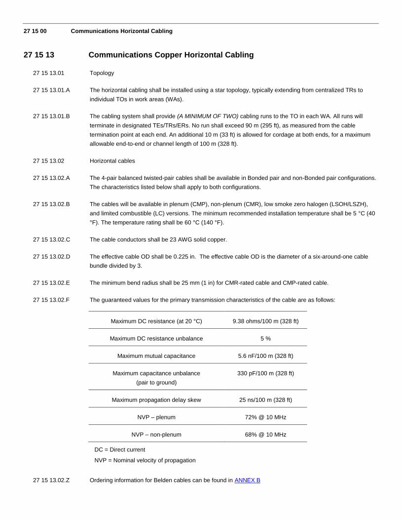
27 15 13.02.F The guaranteed values for the primary transmission characteristics of the cable are as follows:
Maximum DC resistance (at 20 °C) 9.38 ohms/100 m (328 ft)
Maximum DC resistance unbalance 5 %
Maximum mutual capacitance 5.6 nF/100 m (328 ft)
Maximum capacitance unbalance
(pair to ground)
330 pF/100 m (328 ft)
Maximum propagation delay skew 25 ns/100 m (328 ft)
NVP – plenum 72% @ 10 MHz
NVP – non-plenum 68% @ 10 MHz
DC = Direct current
NVP = Nominal velocity of propagation
27 15 13.02.Z Ordering information for Belden cables can be found in ANNEX B

February 2017 Belden System 2400 Page 18 MasterFormat Bid Specification Template Rev 3.1
27 15 13.03 Horizontal cable installation
27 15 13.03.A Horizontal cables shall be installed in accordance with TIA standards-based recommendations, the
manufacturer’s recommendations/installation guides, and industry best practices.
27 15 13.03.B A plastic or nylon pull cord with a minimum test rating of 90 kg (200 lb) shall be co-installed with the cable in
any conduit.
27 15 13.03.C Cable raceways shall not be filled greater than the TIA-569-C recommended maximum fill for the particular
raceway type, or 40%.
27 15 13.03.D Cables shall be installed in continuous lengths from origin to destination. An exception is made for one CP in
any cabling run.
27 15 13.03.E Where cables are installed in an air return plenum, any non-plenum cable shall be installed in metallic conduit.
27 15 13.03.F If CPs are used, they shall be placed in accessible locations and housed in suitable enclosures intended for
that purpose.
27 15 13.03.G If a J-hook or trapeze system is used to support cable bundles, all horizontal cables shall be supported at
every 1.2 m to 1.5 m (48 in to 60 in) intervals. It is recommended that the support surface is rounded without
any sharp edges and at least 2 inches wide. At no point shall cable(s) rest on acoustic ceiling grids or panels.
27 15 13.03.H Horizontal cables shall be bundled in groups of no more than 50 cables. Cable bundle quantities in excess of
50 cables may cause deformation of the bottom cables within the bundles, which will degrade the
performance of those cables.
27 15 13.03.I Cable shall be installed above fire-sprinkler systems and shall not be attached to such systems or any
associated ancillary equipment or hardware. The cabling system and its associated pathways shall be
installed so that they do not obscure any valves, fire alarm conduit(s), boxes, or other control devices.
27 15 13.03.J Cables shall not be attached to ceiling grid or lighting fixture wires. Where support for horizontal cable is
required, the Vendor shall install appropriate carriers to support the cabling.
27 15 13.03.K Any cable damaged or exceeding recommended installation parameters during installation shall be replaced
by the Vendor prior to final acceptance at no cost to the owner of the Belden System 2400.
27 15 13.03.L Cables shall be identified by a self-adhesive label in accordance with Section 27 05 53 of this document and
TIA -606-B. The cable label shall be applied to the cable behind the faceplate, on a section of cable that can
be accessed by removing the cover plate.
27 15 13.03.M Balanced twisted-pair cable shall be installed so that there are no bends smaller than 4 times the OD of the
cable at any point in the run or at the termination points.
27 15 13.03.N The pulling tension on any 4-pair balanced twisted-pair cable shall not exceed 110 N (25 lbf).
27 15 43 Communications Faceplates and Connectors
27 15 43.01 General

27 15 43.01.A Each horizontal cable shall be terminated at its designated WA in a modular connector assembly using a
KeyConnect module designed to snap into a faceplate.
27 15 43.01.B The WA modular connector assembly/faceplate shall accommodate:
1. A minimum of two cabling runs.
2. Blank fillers, to be installed in any outlet port in the faceplate that is not occupied by a modular connector
assembly.
27 15 43.01.C Multiple WA outlets that are in close proximity on drawings (and not separated by physical barriers) may be
combined in a single faceplate. The Vendor shall be responsible for determining the optimum compliant
configuration.
27 15 43.01.D The same orientation and positioning of modular connector assemblies on faceplates shall be used
throughout the project. Prior to installation, the Vendor shall submit the proposed configuration(s) for WA
modular connector assemblies/faceplates for approval by the owner of the Belden System 2400.
27 15 43.01.E All WA outlets shall accommodate printed label strips for outlet identification purposes. Printed labels shall be
permanent and shall comply with TIA -606-B. Handwritten labels shall not be accepted.
27 15 43.02 FACEPLATES
27 15 43.02.A The faceplate housing the modular connector assemblies shall provide a symmetrically centered appearance
for the modules.
27 15 43.02.B The faceplate housing the modular connector assemblies shall have no visible mounting screws.
27 15 43.02.C The faceplate housing the modular connector assemblies shall have built-in labeling windows to facilitate
outlet identification.
27 15 43.02.D The faceplates shall be available in 2 different styles: fixed-port design faceplate (wall-mounting) and adapters
(modular furniture, surface-mount) as well as modular design (field-configurable).
27 15 43.02.E All faceplates designs shall be compatible with UTP, F/UTP and multimedia modules.
27 15 43.02.F All plastic faceplates shall be made of UV-stable fire-retardant UL 94V-0 material.
27 15 43.02.G All plastic faceplates shall have the option of being mounted on adapter boxes for surface mount installation.
27 15 43.02.G The stainless steel faceplates shall be made of brushed stainless steel and shall have a fire-retardant plastic
insert UL94V-0 to snap connector.
27 15 43.02.G The field-configurable faceplate shall have a modular design that allows connectors to be inserted and
removed from the frame without unscrewing it from the wall. [NOTE: Use this requirement only if specifying
MediaFlex Outlets]
27 15 43.02.G The field-configurable faceplates shall be compatible with both keystone-style and Belden Proprietary MDVO-
style module footprint for optimal flexibility in the design of the workstation outlet. [NOTE: Use this requirement
only if specifying MediaFlex Outlets]
27 15 43.02.X Ordering information for Belden Faceplates can be found in Annex B
February 2017 Belden System 2400 Page 20 MasterFormat Bid Specification Template Rev 3.1
27 15 43.03 Connectors
27 15 43.03.A The modular jack assemblies used to terminate the 4-pair balanced twisted-pair cable shall have
the characteristics listed below.
27 15 43.03.B The connectors shall be modular in form, with available mounting options for TOs, CPs, rack-mount
panels, and wall-mount panels.
27 15 43.03.C The connector termination method shall involve no pair separation making bonded-pair cable quick
and easy to terminate. [NOTE: Use this requirement only if specifying REVConnect connectors]
27 15 43.03.D The connector termination method shall offer the possibility to change the connector interface
without having to re-terminated the cable (ex.: Change jack color or replace a jack by a plug
interface) [NOTE: Use this requirement only if specifying REVConnect connectors]
27 15 43.03.E The connectors shall use an encapsulated lead frame technology ensuring long-term reliability as
well as stable transmission performance.
27 15 43.03.F The connectors shall use a plastic element to position and hold each cable pair at a right angle to
its corresponding IDC termination point.
27 15 43.03.G The connectors shall incorporate crosstalk compensation and impedance matching circuitry
ensuring additional NEXT, FEXT, insertion loss and return loss margin beyond minimum Category
6 requirements to guarantee transmission performance up to 300 MHz.
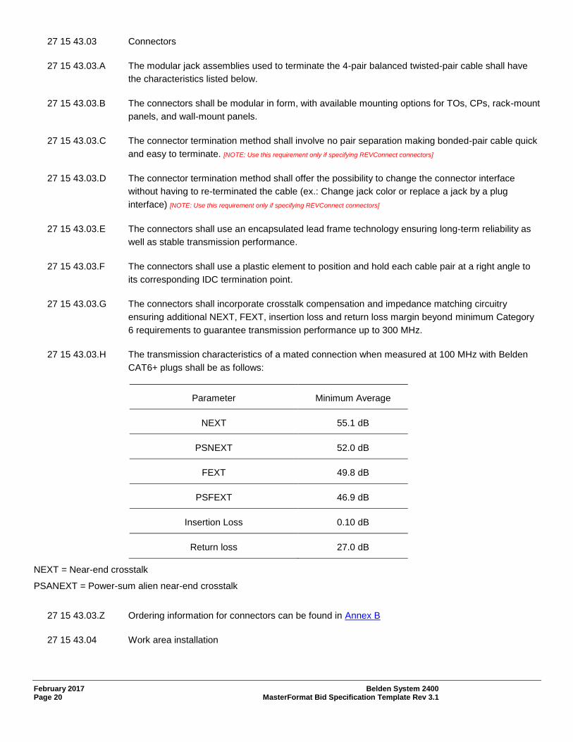
27 15 43.03.H The transmission characteristics of a mated connection when measured at 100 MHz with Belden
CAT6+ plugs shall be as follows:
Parameter Minimum Average
NEXT 55.1 dB
PSNEXT 52.0 dB
FEXT 49.8 dB
PSFEXT 46.9 dB
Insertion Loss 0.10 dB
Return loss 27.0 dB
NEXT = Near-end crosstalk
PSANEXT = Power-sum alien near-end crosstalk
27 15 43.03.Z Ordering information for connectors can be found in Annex B
27 15 43.04 Work area installation

27 15 43.04.A Work area TOs shall be installed in accordance with standards-based recommendations, the
manufacturer’s recommendations/installation guides, and industry best practices.
27 15 43.04.B Cables shall be dressed and terminated in accordance with standards-based recommendations,
the manufacturer’s recommendations/installation guides, and industry best practices.
27 15 43.04.C Slack cable shall be coiled in flush or surface-mount TOs if adequate space is provided to house
the cable coil without exceeding the manufacturer’s bend radius limitations. In hollow-wall
installations where box eliminators are used, cable slack can be stored in the wall. No more than
300 mm (12 in) of slack shall be stored in a TO, modular furniture raceway, or insulated wall.
Excess slack may be loosely coiled and stored in the ceiling above each WA.
27 15 43.04.D The twisted pairs shall be guided, positioned and secured at the connector termination point using
a termination bar that locks the pairs in place to prevent untwisting of pairs into the cable when
terminating the conductors.
27 15 43.04.E Bend radius of the cable in the termination area shall not be less than 4 times the OD of the cable.
27 15 43.04.F Data outlets (unless otherwise noted in drawings) shall occupy the bottom positions on faceplates.
Data outlets in horizontally oriented faceplates shall occupy the right-most positions.
27 15 43.04.G Voice outlets (unless otherwise noted in drawings) shall occupy the top positions on faceplates.
Voice outlets in horizontally oriented faceplates shall occupy the left-most positions.
February 2017 Belden System 2400 Page 22 MasterFormat Bid Specification Template Rev 3.1
27 16 00 Communications Connecting Cords, Devices, and Adapters
27 16 19 Communications Patch Cords, Station Cords, and Cross-Connect Wire
27 16 19.01 Cordage
27 16 19.01.A The work area cords, patch cords, and equipment cords/pigtails shall meet TIA-568-C.2 Category 6
standard and ISO/IEC 11801 Class E standard for component compliance. The modular cords
shall also meet reliability requirements of TIA/EIA-568-B.2, Normative Annex F.4.3.1 with a
minimum Return Loss margin of 3 dB throughout each step of the mechanical stress test
procedure.
27 16 19.01.B The modular cord shall use minimum 24 AWG solid copper conductors and shall be made with
bonded-pair cable to provide structural integrity and stable transmission performance in
environments where frequent moves, adds, and changes are routine. A crossweb element shall be
used for consistent pair separation and minimal NEXT coupling. The nominal cable diameter of the
modular cord shall be 6.0 mm (0.24 in).
27 16 19.01.D The modular cords shall be available in standard colors (Brown, Red, Orange, Yellow, Green, Blue,
Purple, Gray, White, Black) and also TIA 606-A Pantone colors (Red, Orange, Yellow, Green, Blue,
Purple).
27 16 19.01.E The management bar technology of the modular cord shall have tightly controlled and centered
plug NEXT performance. The tolerance on de-embedded plug NEXT shall be within half the range
specified in the TIA Category 6 standard for the 3-6 / 4-5 pair combination.
27 16 19.01.F The modular cords shall be available in standard or traceable versions. Traceable versions shall
include a button-activated LED light within the plug head, such that activation of which will cause
LEDs to flash on both ends of patch cord for easy tracing and identification.
27 16 19.01.Z Ordering information for modular cords can be found in Annex B
ANNEX A: ADDITIONAL INFORMATION
NOTE: Firestop installation is a critical safety element. If penetrations must be introduced to one or more fire-rated barriers for the purpose of installing pathways or cabling, include this section.
Division 07 – THERMAL AND MOISTURE PROTECTION
07 80 00 Fire and Smoke Protection
07 84 00 Firestopping
07 84 13 Penetration Firestopping
07 84 13.01 firestop system
07 84 13.01.A A firestop system consists of the item or items penetrating the fire-rated barrier, the opening in the
barrier, and the materials used to seal and restore the fire integrity of the penetrated barrier.
Firestop systems serve as an effective block against fire, smoke, heat, vapor, and pressurized
water streams.
07 84 13.01.B All penetrations through fire-rated building structures (e.g., walls, floors) shall be sealed with an
appropriate firestop system. This requirement applies to “through” penetrations (complete
penetration) as well as “membrane” penetrations (through one side of a hollow structure). Any
penetrating items (e.g., riser slots and sleeves, cables, conduits, cable trays, raceways) shall be
properly firestopped.
07 84 13.01.C Firestop systems shall be UL Classified to ASTM E814 – Standard Test Method for Fire Tests of
Through-Penetration Fire Stops (UL 1479) and shall be approved by a qualified PE licensed in the
jurisdiction where the work is to be performed. One or more drawings illustrating the deployment of
the proposed firestop system(s), stamped or embossed by the PE, shall be provided to the owner
of the Belden System 2400 prior to installing the firestop system(s).
07 84 13.02 Firestop system installation
07 84 13.02.A All firestop systems shall be installed in accordance with the manufacturer’s
recommendations/installation guides and shall be available for inspection by the local AHJ prior to
acceptance.
February 2017 Belden System 2400 Page 24 MasterFormat Bid Specification Template Rev 3.1
ANNEX B: PRODUCT ORDERING INFORMATION
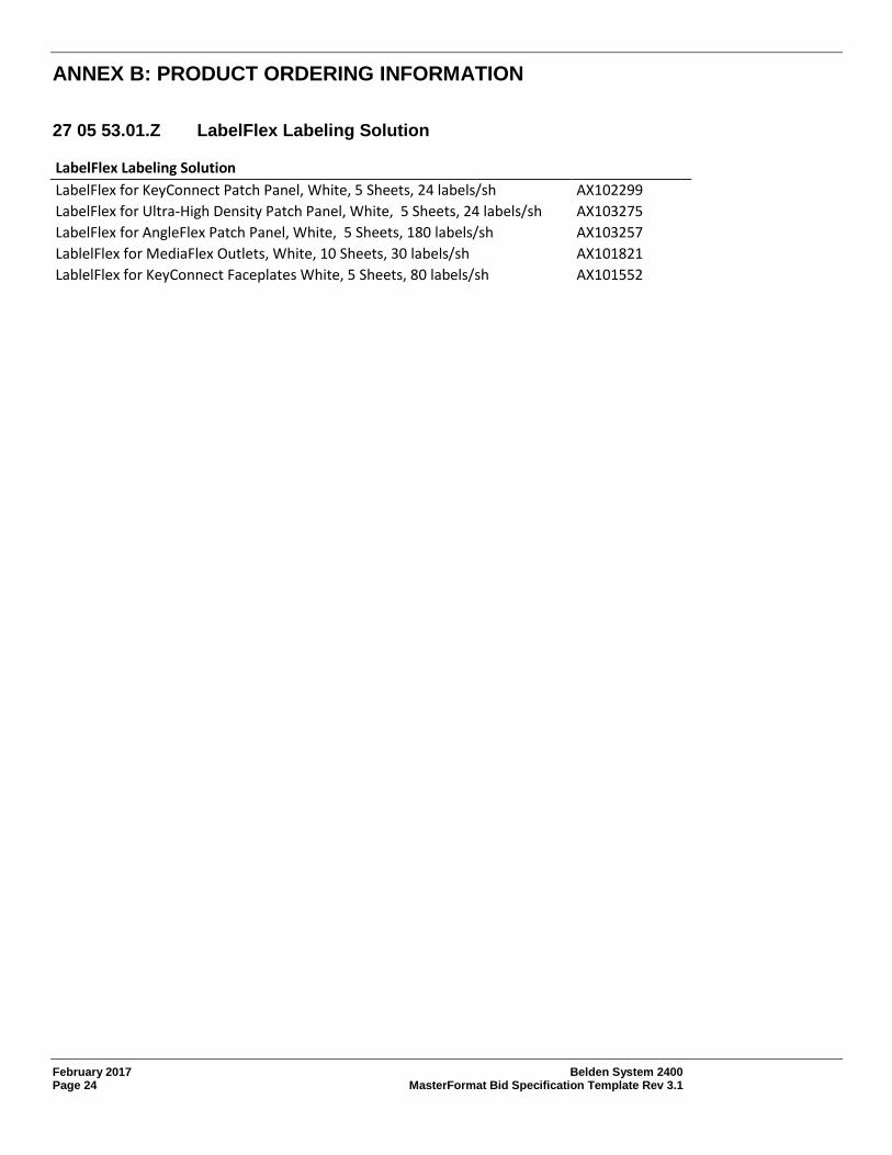
27 05 53.01.Z LabelFlex Labeling Solution
LabelFlex Labeling Solution
LabelFlex for KeyConnect Patch Panel, White, 5 Sheets, 24 labels/sh AX102299
LabelFlex for Ultra-High Density Patch Panel, White, 5 Sheets, 24 labels/sh AX103275
LabelFlex for AngleFlex Patch Panel, White, 5 Sheets, 180 labels/sh AX103257
LablelFlex for MediaFlex Outlets, White, 10 Sheets, 30 labels/sh AX101821
LablelFlex for KeyConnect Faceplates White, 5 Sheets, 80 labels/sh AX101552

27 11 16.01.Z High-density Racking System
High-density Racking System Part No.
Steel relay rack, 19" W x 84" H, #12-24 tapped holes, Black, Knock Down XDR8419-312N
Steel relay rack, 19" W x 84" H, #12-24 tapped hole, Black, Welded XDR8419-312W
Single-sided High-density Vertical Manager
High-density with doors, 3-5/8” W x 84" H, Black BHVH003
High-density with doors, 6” W x 84" H, Black BHVH006
High-density with doors, 10” W x 84" H, Black BHVH010
High-density with doors, 12” W x 84" H, Black BHVH012
Double-sided High-density Vertical Manager
High-density with doors, 3-5/8” W x 84" H, Black BHVHH03
High-density with doors, 6” W x 84" H, Black BHVHH06
High-density with doors, 10” W x 84" H, Black BHVHH10
High-density with doors, 12” W x 84" H, Black BHVHH12
Vertical Manager Backcover
3-5/8" W, Black BHBC03X
6 " W, Black BHBC06X
10" W, Black BHBC10X
12" W, Black BHBC12X
Vertical Manager Doors (1 Pair)
3-5/8" W, Black BHDK03X
6" W, Black BHDK06X
10" W, Black BHDK10X
12" W, Black BHDK12X
Horizontal Manager with Cover
19" W x 1U, Black BHH191U
19" W x 2U, Black BHH192U
19" W x 3U, Black BHH193U
February 2017 Belden System 2400 Page 26 MasterFormat Bid Specification Template Rev 3.1
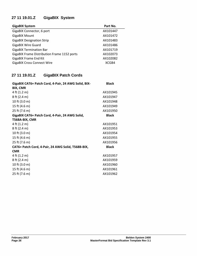
27 11 19.01.Z GigaBIX System
GigaBIX System Part No.
GigaBIX Connector, 6 port AX101447
GigaBIX Mount AX101472
GigaBIX Designation Strip AX101483
GigaBIX Wire Guard AX101486
GigaBIX Termination Bar GigaBIX Frame Distribution Frame 1152 ports GigaBIX Frame End Kit
AX101719 AX102073 AX102082
GigaBIX Cross Connect Wire XCGB4
27 11 19.01.Z GigaBIX Patch Cords
GigaBIX CAT6+ Patch Cord, 4-Pair, 24 AWG Solid, BIX-BIX, CMR
Black
4 ft (1.2 m) AX101945
8 ft (2.4 m) AX101947
10 ft (3.0 m) AX101948
15 ft (4.6 m) AX101949
25 ft (7.6 m) AX101950
GigaBIX CAT6+ Patch Cord, 4-Pair, 24 AWG Solid, T568A-BIX, CMR
Black
4 ft (1.2 m) AX101951 8 ft (2.4 m) AX101953
10 ft (3.0 m) AX101954
15 ft (4.6 m) AX101955
25 ft (7.6 m) AX101956
CAT6+ Patch Cord, 4-Pair, 24 AWG Solid, T568B-BIX, CMR
Black
4 ft (1.2 m) AX101957 8 ft (2.4 m) AX101959
10 ft (3.0 m) AX101960
15 ft (4.6 m) AX101961
25 ft (7.6 m) AX101962

27 11 19.03.Z KeyConnect Patch Panels
CAT6+ HD Patch Panels (Preloaded, inline 110 punch) Part No.
CAT6+ HD-110 Patch Panel, 24-port, 1U, Black (Preloaded) AX105520
CAT6+ HD-110 Patch Panel, 48-port, 2U, Black (Preloaded) AX105521
CAT6+ KeyConnect Patch Panels (Preloaded)
CAT6+ KeyConnect Patch Panel, 24-port, 1U, Black, Preloaded AX103253
CAT6+ KeyConnect Patch Panel, 24-port, 1U, Black, Short Cable Management, Preloaded AX103253-SCM
CAT6+ KeyConnect Patch Panel, 48-port, 2U, Black, Preloaded AX103255
CAT6+ KeyConnect Patch Panel, 48-port, 2U, Black, Short Cable Management, Preloaded AX103255-SCM
CAT6+ Ultra High Density Patch Panel (Preloaded)
CAT6+ Ultra High-Density Patch Panel, 48-port, 1U, Black (Preloaded) AX103263
CAT6+ KeyConnect Angled Patch Panel (Preloaded)
CAT6+ KeyConnect Angled Patch Panel, 24‐port, 1U, Black (Preloaded) AX105360
CAT6+ KeyConnect Angled Patch Panel, 48‐port, 2U, Black (Preloaded) AX105361
CAT6+ KeyConnect Angled Patch Panel, 48‐port, 1U, Black (Preloaded) AX105362
KeyConnect Modular Patch Panels (Empty)
KeyConnect Modular Patch Panel, 24-port, 1U, Black (Empty) AX103114
KeyConnect Modular Patch Panel, 48-port, 1U, Black (Empty) AX103121
KeyConnect Modular Patch Panel, 48-port, 2U, Black (Empty) AX103115
KeyConnect Modular Patch Panel, 72-port, 2U, Black (Empty) AX103116
KeyConnect Modular Patch Panel, 96-port, 3U, Black (Empty) AX105371
KeyConnect AngleFlex Patch Panels (Empty)
KeyConnect AngleFlex Patch Panel, 24-port, 1U, Black (Empty) AX103248
KeyConnect AngleFlex Patch Panel, 48-port, 2U, Black (Empty) AX103249
KeyConnect Angled Patch Panels (Empty)
KeyConnect Angled Patch Panel, 24‐port, 1U, Black (Empty) AX104599
KeyConnect Angled Patch Panel, 48‐port, 2U, Black (Empty) AX104601
KeyConnect Angled Patch Panel, 48‐port, 1U, Black (Empty) AX104600
KeyConnect Front Access Patch Panels
KeyConnect Front Access Patch Panel, 24-port, 1U, Black KeyConnect Front Access Patch Panel, 48-port, 2U, Black KeyConnect Front Access Patch Panel, 72-port, 2U, Black Labeling Kit (12 strips and LabelFlex sheets for 96 ports) Spare Bezel Kit for Front Access Patch Panel, 24-Pack
AX106288 AX106289 AX106290 AX106291
AX106292-B24
February 2017 Belden System 2400 Page 28 MasterFormat Bid Specification Template Rev 3.1
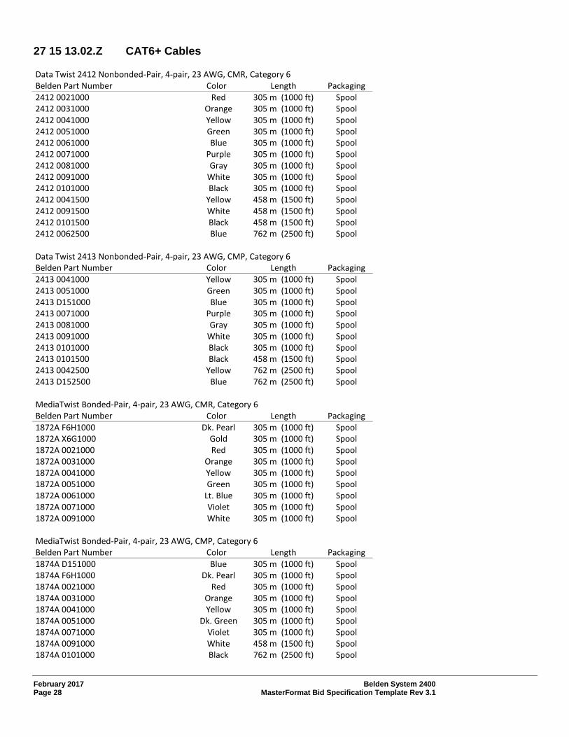
27 15 13.02.Z CAT6+ Cables
Data Twist 2412 Nonbonded-Pair, 4-pair, 23 AWG, CMR, Category 6 Belden Part Number Color Length Packaging
2412 0021000 Red 305 m (1000 ft) Spool 2412 0031000 Orange 305 m (1000 ft) Spool 2412 0041000 Yellow 305 m (1000 ft) Spool 2412 0051000 Green 305 m (1000 ft) Spool 2412 0061000 Blue 305 m (1000 ft) Spool 2412 0071000 Purple 305 m (1000 ft) Spool 2412 0081000 Gray 305 m (1000 ft) Spool 2412 0091000 White 305 m (1000 ft) Spool 2412 0101000 Black 305 m (1000 ft) Spool 2412 0041500 Yellow 458 m (1500 ft) Spool 2412 0091500 White 458 m (1500 ft) Spool 2412 0101500 Black 458 m (1500 ft) Spool 2412 0062500 Blue 762 m (2500 ft) Spool
Data Twist 2413 Nonbonded-Pair, 4-pair, 23 AWG, CMP, Category 6 Belden Part Number Color Length Packaging
2413 0041000 Yellow 305 m (1000 ft) Spool 2413 0051000 Green 305 m (1000 ft) Spool 2413 D151000 Blue 305 m (1000 ft) Spool 2413 0071000 Purple 305 m (1000 ft) Spool 2413 0081000 Gray 305 m (1000 ft) Spool 2413 0091000 White 305 m (1000 ft) Spool 2413 0101000 Black 305 m (1000 ft) Spool 2413 0101500 Black 458 m (1500 ft) Spool 2413 0042500 Yellow 762 m (2500 ft) Spool 2413 D152500 Blue 762 m (2500 ft) Spool MediaTwist Bonded-Pair, 4-pair, 23 AWG, CMR, Category 6 Belden Part Number Color Length Packaging
1872A F6H1000 Dk. Pearl 305 m (1000 ft) Spool 1872A X6G1000 Gold 305 m (1000 ft) Spool 1872A 0021000 Red 305 m (1000 ft) Spool 1872A 0031000 Orange 305 m (1000 ft) Spool 1872A 0041000 Yellow 305 m (1000 ft) Spool 1872A 0051000 Green 305 m (1000 ft) Spool 1872A 0061000 Lt. Blue 305 m (1000 ft) Spool 1872A 0071000 Violet 305 m (1000 ft) Spool 1872A 0091000 White 305 m (1000 ft) Spool
MediaTwist Bonded-Pair, 4-pair, 23 AWG, CMP, Category 6 Belden Part Number Color Length Packaging
1874A D151000 Blue 305 m (1000 ft) Spool 1874A F6H1000 Dk. Pearl 305 m (1000 ft) Spool 1874A 0021000 Red 305 m (1000 ft) Spool 1874A 0031000 Orange 305 m (1000 ft) Spool 1874A 0041000 Yellow 305 m (1000 ft) Spool 1874A 0051000 Dk. Green 305 m (1000 ft) Spool 1874A 0071000 Violet 305 m (1000 ft) Spool 1874A 0091000 White 458 m (1500 ft) Spool 1874A 0101000 Black 762 m (2500 ft) Spool
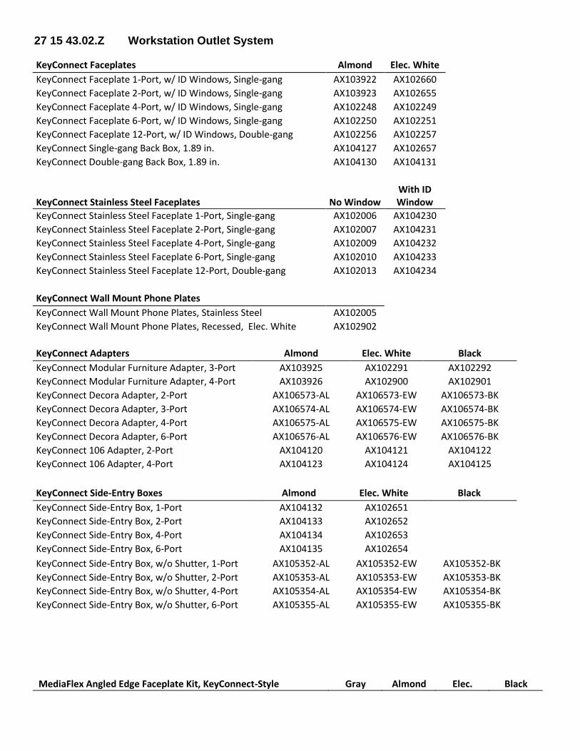
27 15 43.02.Z Workstation Outlet System
KeyConnect Faceplates Almond Elec. White
KeyConnect Faceplate 1-Port, w/ ID Windows, Single-gang AX103922 AX102660
KeyConnect Faceplate 2-Port, w/ ID Windows, Single-gang AX103923 AX102655
KeyConnect Faceplate 4-Port, w/ ID Windows, Single-gang AX102248 AX102249
KeyConnect Faceplate 6-Port, w/ ID Windows, Single-gang AX102250 AX102251
KeyConnect Faceplate 12-Port, w/ ID Windows, Double-gang AX102256 AX102257
KeyConnect Single-gang Back Box, 1.89 in. AX104127 AX102657
KeyConnect Double-gang Back Box, 1.89 in. AX104130 AX104131
KeyConnect Stainless Steel Faceplates No Window With ID Window
KeyConnect Stainless Steel Faceplate 1-Port, Single-gang AX102006 AX104230
KeyConnect Stainless Steel Faceplate 2-Port, Single-gang AX102007 AX104231
KeyConnect Stainless Steel Faceplate 4-Port, Single-gang AX102009 AX104232
KeyConnect Stainless Steel Faceplate 6-Port, Single-gang AX102010 AX104233
KeyConnect Stainless Steel Faceplate 12-Port, Double-gang AX102013 AX104234
KeyConnect Wall Mount Phone Plates
KeyConnect Wall Mount Phone Plates, Stainless Steel AX102005
KeyConnect Wall Mount Phone Plates, Recessed, Elec. White AX102902
KeyConnect Adapters Almond Elec. White Black
KeyConnect Modular Furniture Adapter, 3-Port AX103925 AX102291 AX102292
KeyConnect Modular Furniture Adapter, 4-Port AX103926 AX102900 AX102901
KeyConnect Decora Adapter, 2-Port AX106573-AL AX106573-EW AX106573-BK
KeyConnect Decora Adapter, 3-Port AX106574-AL AX106574-EW AX106574-BK
KeyConnect Decora Adapter, 4-Port AX106575-AL AX106575-EW AX106575-BK
KeyConnect Decora Adapter, 6-Port AX106576-AL AX106576-EW AX106576-BK
KeyConnect 106 Adapter, 2-Port AX104120 AX104121 AX104122
KeyConnect 106 Adapter, 4-Port AX104123 AX104124 AX104125
KeyConnect Side-Entry Boxes Almond Elec. White Black
KeyConnect Side-Entry Box, 1-Port AX104132 AX102651
KeyConnect Side-Entry Box, 2-Port AX104133 AX102652
KeyConnect Side-Entry Box, 4-Port AX104134 AX102653
KeyConnect Side-Entry Box, 6-Port AX104135 AX102654
KeyConnect Side-Entry Box, w/o Shutter, 1-Port AX105352-AL AX105352-EW AX105352-BK
KeyConnect Side-Entry Box, w/o Shutter, 2-Port AX105353-AL AX105353-EW AX105353-BK
KeyConnect Side-Entry Box, w/o Shutter, 4-Port AX105354-AL AX105354-EW AX105354-BK
KeyConnect Side-Entry Box, w/o Shutter, 6-Port AX105355-AL AX105355-EW AX105355-BK
MediaFlex Angled Edge Faceplate Kit, KeyConnect-Style Gray Almond Elec. Black
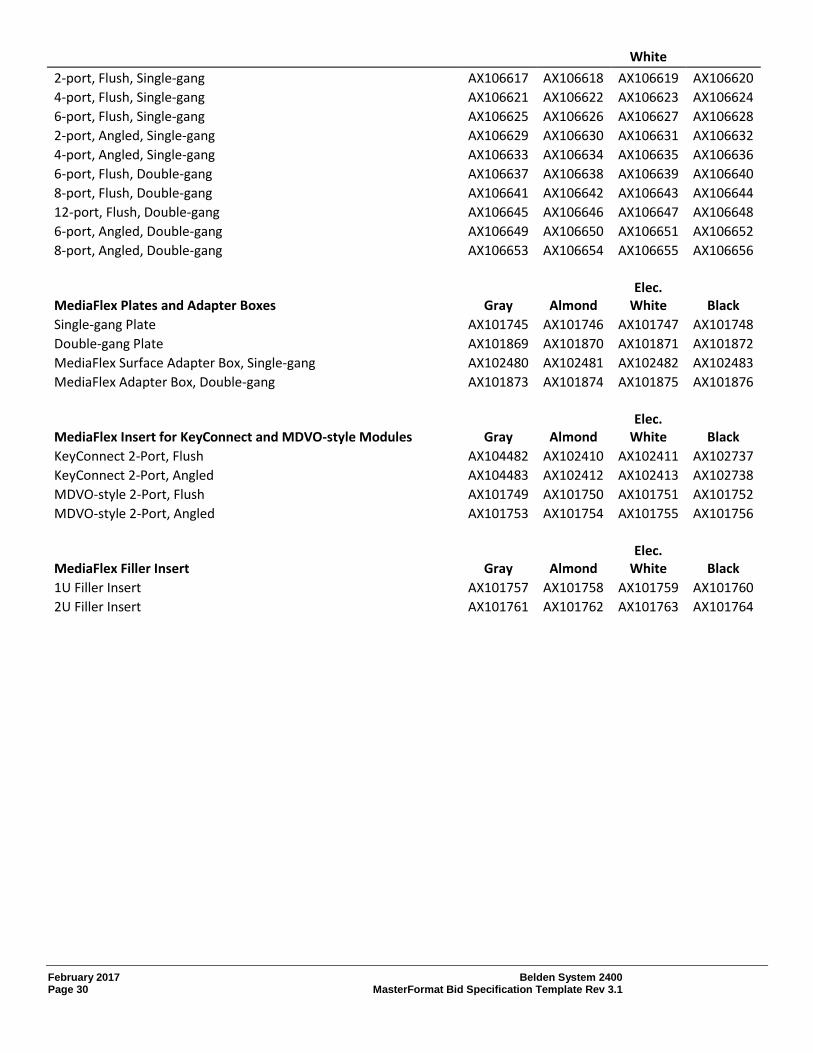
February 2017 Belden System 2400 Page 30 MasterFormat Bid Specification Template Rev 3.1
White
2-port, Flush, Single-gang AX106617 AX106618 AX106619 AX106620
4-port, Flush, Single-gang AX106621 AX106622 AX106623 AX106624
6-port, Flush, Single-gang AX106625 AX106626 AX106627 AX106628
2-port, Angled, Single-gang AX106629 AX106630 AX106631 AX106632
4-port, Angled, Single-gang AX106633 AX106634 AX106635 AX106636
6-port, Flush, Double-gang AX106637 AX106638 AX106639 AX106640
8-port, Flush, Double-gang AX106641 AX106642 AX106643 AX106644
12-port, Flush, Double-gang AX106645 AX106646 AX106647 AX106648
6-port, Angled, Double-gang AX106649 AX106650 AX106651 AX106652
8-port, Angled, Double-gang AX106653 AX106654 AX106655 AX106656
MediaFlex Plates and Adapter Boxes Gray Almond Elec.
White Black
Single-gang Plate AX101745 AX101746 AX101747 AX101748
Double-gang Plate AX101869 AX101870 AX101871 AX101872
MediaFlex Surface Adapter Box, Single-gang AX102480 AX102481 AX102482 AX102483
MediaFlex Adapter Box, Double-gang AX101873 AX101874 AX101875 AX101876
MediaFlex Insert for KeyConnect and MDVO-style Modules Gray Almond Elec.
White Black
KeyConnect 2-Port, Flush AX104482 AX102410 AX102411 AX102737
KeyConnect 2-Port, Angled AX104483 AX102412 AX102413 AX102738
MDVO-style 2-Port, Flush AX101749 AX101750 AX101751 AX101752
MDVO-style 2-Port, Angled AX101753 AX101754 AX101755 AX101756
MediaFlex Filler Insert Gray Almond Elec.
White Black
1U Filler Insert AX101757 AX101758 AX101759 AX101760
2U Filler Insert AX101761 AX101762 AX101763 AX101764
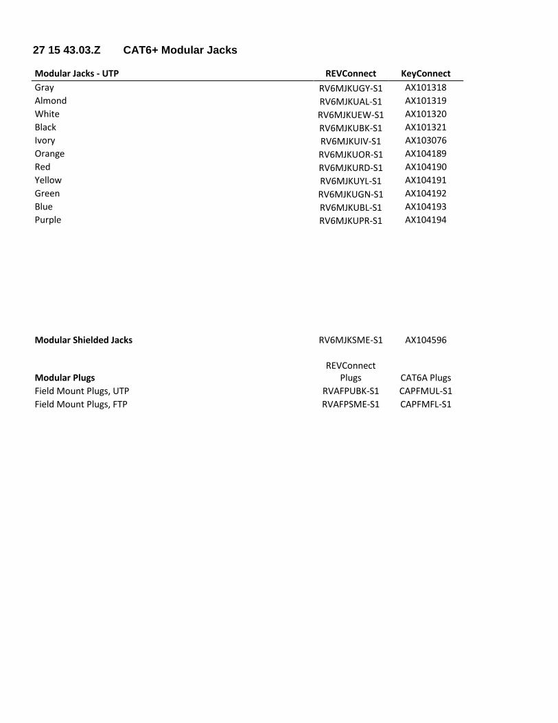
27 15 43.03.Z CAT6+ Modular Jacks
Modular Jacks - UTP REVConnect KeyConnect
Gray RV6MJKUGY-S1 AX101318
Almond RV6MJKUAL-S1 AX101319
White RV6MJKUEW-S1 AX101320
Black RV6MJKUBK-S1 AX101321
Ivory RV6MJKUIV-S1 AX103076
Orange RV6MJKUOR-S1 AX104189
Red RV6MJKURD-S1 AX104190
Yellow RV6MJKUYL-S1 AX104191
Green RV6MJKUGN-S1 AX104192
Blue RV6MJKUBL-S1 AX104193
Purple RV6MJKUPR-S1 AX104194
Modular Shielded Jacks RV6MJKSME-S1 AX104596
Modular Plugs REVConnect
Plugs CAT6A Plugs
Field Mount Plugs, UTP RVAFPUBK-S1 CAPFMUL-S1
Field Mount Plugs, FTP RVAFPSME-S1 CAPFMFL-S1
February 2017 Belden System 2400 Page 32 MasterFormat Bid Specification Template Rev 3.1
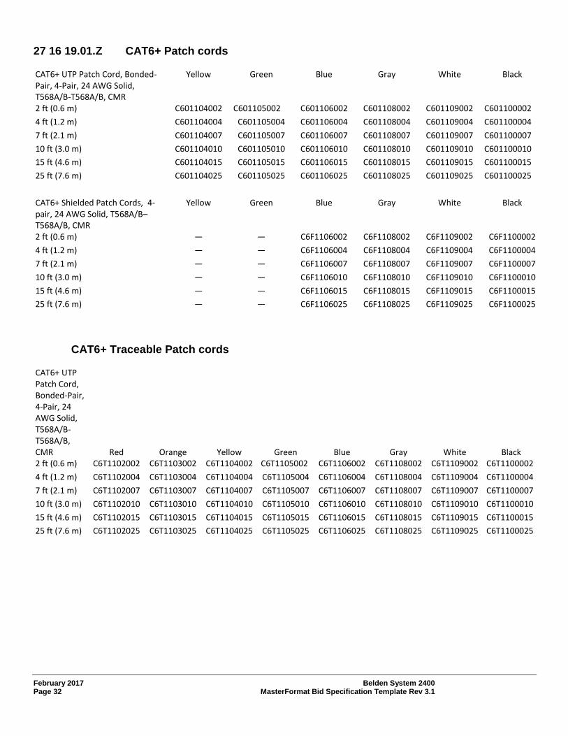
27 16 19.01.Z CAT6+ Patch cords
CAT6+ UTP Patch Cord, Bonded-Pair, 4-Pair, 24 AWG Solid, T568A/B-T568A/B, CMR
Yellow Green Blue Gray White Black
2 ft (0.6 m) C601104002 C601105002 C601106002 C601108002 C601109002 C601100002
4 ft (1.2 m) C601104004 C601105004 C601106004 C601108004 C601109004 C601100004
7 ft (2.1 m) C601104007 C601105007 C601106007 C601108007 C601109007 C601100007
10 ft (3.0 m) C601104010 C601105010 C601106010 C601108010 C601109010 C601100010
15 ft (4.6 m) C601104015 C601105015 C601106015 C601108015 C601109015 C601100015
25 ft (7.6 m) C601104025 C601105025 C601106025 C601108025 C601109025 C601100025
CAT6+ Shielded Patch Cords, 4-pair, 24 AWG Solid, T568A/B–T568A/B, CMR
Yellow Green Blue Gray White Black
2 ft (0.6 m) — — C6F1106002 C6F1108002 C6F1109002 C6F1100002
4 ft (1.2 m) — — C6F1106004 C6F1108004 C6F1109004 C6F1100004
7 ft (2.1 m) — — C6F1106007 C6F1108007 C6F1109007 C6F1100007
10 ft (3.0 m) — — C6F1106010 C6F1108010 C6F1109010 C6F1100010
15 ft (4.6 m) — — C6F1106015 C6F1108015 C6F1109015 C6F1100015
25 ft (7.6 m) — — C6F1106025 C6F1108025 C6F1109025 C6F1100025
CAT6+ Traceable Patch cords
CAT6+ UTP Patch Cord, Bonded-Pair, 4-Pair, 24 AWG Solid, T568A/B-T568A/B, CMR Red Orange Yellow Green Blue Gray White Black 2 ft (0.6 m) C6T1102002 C6T1103002 C6T1104002 C6T1105002 C6T1106002 C6T1108002 C6T1109002 C6T1100002
4 ft (1.2 m) C6T1102004 C6T1103004 C6T1104004 C6T1105004 C6T1106004 C6T1108004 C6T1109004 C6T1100004
7 ft (2.1 m) C6T1102007 C6T1103007 C6T1104007 C6T1105007 C6T1106007 C6T1108007 C6T1109007 C6T1100007
10 ft (3.0 m) C6T1102010 C6T1103010 C6T1104010 C6T1105010 C6T1106010 C6T1108010 C6T1109010 C6T1100010
15 ft (4.6 m) C6T1102015 C6T1103015 C6T1104015 C6T1105015 C6T1106015 C6T1108015 C6T1109015 C6T1100015
25 ft (7.6 m) C6T1102025 C6T1103025 C6T1104025 C6T1105025 C6T1106025 C6T1108025 C6T1109025 C6T1100025