town of stonington · the town of stonington would like the ... the cab & chassis and...
TRANSCRIPT
TOWN OF STONINGTON
DEPARTMENT OF
PUBLIC WORKS
INVITATION TO BID
FOR THE PURCHASE OF
CAB & CHASSIS
AND EQUIPMENT
Town Of Stonington
152 Elm Street
Stonington, Connecticut 06378
(860) 535-5055 Fax (860) 535-1023
Prepared for the
Town of Stonington
By Steven A Burdick
2014
2
TOWN OF STONINGTON TRUCK SPECIFICATIONS
Intent
It is the intent of these documents to describe in detail two (2) 2015 International 7400 SFA 4x2 (SA525) Cab
& Chassis, (2) Body Company equipment packages, and all miscellaneous items required to complete the trucks
and equipment packages.
The Town of Stonington would like the Bidder, to work as an “allied” equipment vendor in this Bid and
purchasing process, therefore the truck vendor shall be responsible for handling both the cab & chassis and the
body company installations unless otherwise noted within the quote specifications.
The following specifications describe our minimum requirements for the quality and type of equipment to be
furnished. Bidder may offer equipment which exceeds these requirements. Bids which fail to meet these
minimum requirements will be considered non-responsive to our needs.
The truck Cab & Chassis shall be new and of the latest design and be in current production at the time of the
submission of the bid. All subcontractors installing equipment and components must be an authorized stocking
distributor of that equipment for the purposes of warranty, parts and service.
Availability
The Bidder must indicate the number of calendar days required for the delivery of the completed Trucks and
Equipment packages with the Bid Prior to Receipt of Order. (P.R.0.)
Inspections
The work in progress shall be subject to periodic inspections.
1) When the truck dealer receives the Cab & Chassis.
2) When the truck dealer delivers the completed truck and equipment package to the Town of
Stonington. (Truck will come supplied with its original Order Content Confirmation.)
3) Equipment installation is subjected to additional inspections listed herein this Document.
Pre-Delivery Inspection
The Cab & Chassis and associated options furnished will receive a detailed pre-delivery inspection to assure
compliance with specifications in all aspects of the Cab & Chassis. All aspects of the Cab & Chassis must
match the specifications within this document. The Cab & Chassis will not proceed to the Body Company until
such time the Inspection has been completed and approved.
Body Company Delivery
Awarded Bidder shall be responsible for delivering and receiving the cab & chassis to and from the Body
Company, cleaning, prepping, and delivery of the final product to the Town of Stonington.
Cab & Chassis Warranty
See compliance section.
3
Evaluation
The quality of the equipment supplied, their conformity with the specifications, their suitability to requirements,
delivery terms, guaranty clauses, and price of the materials shall all be taken into consideration. Where
equivalent equipment is offered, the Town of Stonington will determine if the proposed item is equal or better
than that specified.
Design
Materials shall be of good commercial quality for the intended service and shall be produced by use of current
manufacturing processes and treated to resist rust, corrosion and wear.
Standard Equipment
All cab & chassis specifications shall conform to standard equipment unless otherwise specified.
Model Information Required
The manufacturer, make and exact models proposed as substitutes shall also be submitted on bidder’s letterhead
with any proposal contended to be “equivalent”.
Equivalent Proposals
It is the intent of these specifications to describe and govern the purchase of the new and unused cab & chassis
with any and all accessories as noted herein. The cab & chassis shall conform to the highest quality of
manufacturing and design standards. Any item or items not specifically mentioned herein, but which would be
required to produce a complete working unit, shall be supplied by the vendor.
If a Bidder is basing his proposal on equipment other than what is specified in this document and wishes the cab
& chassis he/she proposes to be considered as an “approved equal”, he/she shall submit on a separate sheet, in
the exact format of the technical specifications contained herein, and item by item description of that which
he/she proposes to substitute including any and all variations from or exceptions to the conditions and
specifications herein this document. Failure to comply may result in rejection of proposal.
To be Determined
All instances in which “to be determined” is expressed and written herein this document shall indicate a final
need of approval by the Town of Stonington.
Regulations
All Trucks and associated equipment installation packages will meet all Federal, State, and OSHA regulations
and so be certified.
Informalities
THE BOARD OF SELECTMEN RESERVES THE RIGHT TO ACCEPT OR REJECT ANY OR ALL
BIDS OR TO WAIVE ANY INFORMALITY IN THE BID.
Trade-In
See “trade in” section after compliance check list.
4
Please indicate yes or no to verify compliance with the specifications COMPLIANCE
CODE
YES NO SA52500
The base chassis model will be a 7400 SFA 4x2 with 171.00 wheelbase, 96.00 CA, and 63.00
axle to frame. ____ ____
1570
Tow hook, front (2) frame mounted. ____ ____
1CAG
Frame Rails heat treated alloy steel (120,000 PSI Yield) ; 10.250” x 3.610” x 0.375”
(260.4mm x 91.7mm x 9.5mm) 456.0” (11582mm) maximum OAL ____ ____
1LLA
Bumper Front steel, swept back. Includes : Bumper, Front powder coated gray (Argent) color. ____ ____
1WDS
Frame Extension, Front integral; 20” in front of grille. ____ ____
1WEV
Wheelbase range 146” (370cm) through and including 195” (495cm). ____ ____
2ARU
Axle front non-driving {meritor MFS-16-143A} wide track, I-beam type, 16,000-lb capacity. ____ ____
3770
Springs, front auxiliary rubber. ____ ____
3ADE
Suspension, front, spring parabolic, taper leaf; 16,000-lb capacity, with shock absorbers.
Includes : spring pins rubber bushings, maintenance free. ____ ____
4091
Brake system, Air dual system for straight truck applications. Includes : brake lines color and size
coded nylon, drain valve twist type, dust shields front brake, dust shields rear brake, gauge air
pressure (2) Air 1 and Air 2 gauges located in instrument cluster, parking brake control yellow
knob located on instrument panel, parking brake valve for truck, quick release valve bendix on
rear axle for spring brake release: 1 for 4x2, 2 for 6x4, slack adjusters front automatic, slack
adjusters rear automatic, spring brake modulator valve R-7 for 4x2, SR-7/w relay for 6x4. ____ ____
5
COMPLIANCE
CODE
YES NO
4193
Brakes, front, Air Cam 16.5” x 6”, Includes: 24 SqIn long stroke brake chambers. ____ ____
4619
Trailer connections four wheel, with hand control valve and tractor protection valve for straight
truck. ____ ____
4773
Brake shoes, rear cast. ____ ____
4AZJ
Air brake ABS {bendix antilock brake system} full wheel control system (4- channel) with
automatic traction control. ____ ____
4EDB
Air dryer {meritor wabco system saver 1200} with heater. Includes air dryer location inside left
rail back of cab. ____ ____
4ERC
Brake chambers, spring relocated to rear of rear axle for maximum ground clearance. ____ ____
4ETE
Brake chambers, front axle {Haldex} 24 SqIn. ____ ____
4EVH
Brake chambers, rear axle {MGM TR3030LP3TSHD} 30/30 spring brake. Includes: brake
Chambers, spring (2) rear parking: with truck brakes: All 4x2, 4x4; with tractor brakes: All
4x2, 4x4; 6x4 & 6x6 with rear tandem axles less than 46,000-lb. or GVWR less than 54,000-lb. ____ ____
4LAA
Slack adjusters, front {Haldex} automatic. ____ ____
4LGA
Slack adjusters, rear {Haldex} automatic. ____ ____
6
COMPLIANCE
CODE
YES NO
4NDB
Brakes, rear, Air Cam S-Cam; 16.5” x 7.0”; Includes 30/30 Sq.In. long stroke brake chamber
And spring actuated parking brake. ____ ____
4SBC
Air compressor {Bendix Tu-Flo-550} 13.2 CFM capacity. ____ ____
4WDA
Drain valve (3) Petcocks; for air tanks ____ ____
5708
Steering column tilting. ____ ____
5CAL
Steering wheel 2-spoke, 18” diameter, black. ____ ____
5PTB
Steering gear (2) {Sheppard M-100/M-80} dual power. ____ ____
7BEP
Exhaust system switchback horizontal aftertreatment device, frame mounted right side under
cab; includes single vertical tail pipe, frame mounted right side back of cab. ____ ____
8000
Electrical system 12-volt, standard equipment. Includes Battery box steel with plastic lid. Data
link connector for vehicle programming and diagnostics in cab. Fuses, electrical SAE blade-type.
Hazard switch push on/push off, located on top of steering column cover. Headlight dimmer
switch integral with turn signal lever. Headlight (2) sealed beam, round with chrome plated
bezels. Horn, electric single. Jump start stud located on positive terminal of outermost battery.
Parking light integral with front turn signal and rear tail light. Running light (2) daytime,
included with headlights. Starter switch electric, key operated. Stop, turn, tail & B/U lights dual,
rear, combination with reflector. Turn signal switch self canceling for trucks, manual canceling
for tractors, with lane change feature. Turn signals, front includes reflectors and auxiliary side
turn signals, solid state flashers; flush mounted. Windshield wiper switch 2-speed with wash and
intermittent feature (5 Pre-set delays), integral with turn signal lever. Windshield wipers single
motor, electric, cowl mounted. Wiring, chassis color coded and continuously numbered. ____ ____
8518
Cigar lighter includes ash cup. ____ ____
7
COMPLIANCE
CODE
YES NO
8541
(2) Disc Style Electric Horns. ____ ____
8875
Battery terminals sealed. ____ ____
8GXD
Alternator{Leece-Neville AVI160P2013} brush type; 12 volt 160 amp. Capacity, pad mount,
with remote sense. ____ ____
8HAB
Body builder wiring back of standard cab at left frame or under extended or crew cab at left
Frame; Includes sealed connectors for tail/amber turn/marker backup/accessory power/ground
and sealed connector for stop/turn. ____ ____
8HAG
Electric trailer brake/lights accommodation package to rear of frame; for separate trailer stop,
tail, turn, marker light circuits; Includes electric trailer brake accommodation package with cab
connections for mounting customer installed electric brake unit, less trailer socket. ____ ____
8MUE
Battery system {international} maintenance-free, (4) 12-volt 2600CCA total. ____ ____
8NAA
Tail light wiring modified includes: wiring for standard Lt & Rt tail lights; separate 8.0’ of extra
Cable wiring for Lt & Rt body mounted tail lights. ____ ____
8RGA
2-way radio wiring effects; wiring with 20 amp fuse protection, includes ignition wire with 5 amp
fuse, wire ends heat shrink and routed to center of header console in cab. ____ ____
8RMA
Radio AM/FM/WB/Clock/Bluetooth/USB Input, MP3, Apple device play & control, Bluetooth
For Phone & Music, with multiple speakers. ____ ____
8THB
Back-up alarm electric, 102dBA. ____ ____
8
COMPLIANCE
CODE
YES NO
8THJ
Auxiliary harness 3.0’ for auxiliary front head lights and turn signals for front plow applications. ____ ____
8TKK
Trailer auxiliary feed circuit for electric trailer brake accommodation/Air trailer ABS; with 30
amp fuse and relay, controlled by ignition switch. ____ ____
8VUK
Battery box Aluminum with plastic cover, 18” wide, 2, 3, or 4 battery capacity, mounted right
Side back of cab. ____ ____
8WBW
Jump start stud remote mounted. Includes jump start stud mounted to battery box. ____ ____
8WCL
Horn, air black, single trumpet, air solenoid operated. ____ ____
8WGL
Windshield wiper spd control force wipers to slowest intermittent speed when park brake set and
wipers left on for a predetermined time. ____ ____
8WML
Headlights long life halogen; for two light system. ____ ____
8WPH
Clearance/marker lights (5) {truck lite} amber LED lights, flush mounted on cab or sunshade. ____ ____
8WPZ
Test exterior lights pre-trip inspection will cycle all exterior lamps except back-up lights. ____ ____
8WRB
Headlights on w/wipers headlights will automatically turn on if windshield wipers are turned on. ____ ____
9
COMPLIANCE
CODE
YES NO
8WTL
Starting motor {Delco Remy 39MT} 12 volt; gear reduced, with thermal over-crank protection. ____ ____
8WWJ
Indicator, low coolant level with audible alarm. ____ ____
8WXD
Alarm, parking brake electric horn sounds in repetitive manner when vehicle park brake is “Not”
set with ignition “OFF” and any door opened. ____ ____
8XAH
Circuit breakers manual-reset (main panel) SAE type III with trip indicators, replaces all fuses
except for 5-amp fuses. ____ ____
9585
Fender extensions rubber. ____ ____
9HAN
Insulation, under hood for sound abatement. ____ ____
9HBM
Grille stationary, chrome. ____ ____
9HBN
Insulation, splash panels for sound abatement. ____ ____
9WAC
Bug screen front end; mounted behind grille. ____ ____
9WBC
Front end tilting, fiberglass, with three piece construction; for 2007 & 2010 emissions. ____ ____
10060
Paint schematic, PT-1 single color, design 100. Includes paint schematic ID letters “GM”. ____ ____
10
COMPLIANCE
CODE
YES NO
10761
Paint type base coat/clear coat, 1-2 tone. ____ ____
11001
Clutch Omit item (clutch & control). ____ ____
12926
Radiator hoses, silicone; molded. ____ ____
12NWC
Engine, diesel {Navistar N9} EPA 10, SCR, 300 HP @ 2000 RPM, 860 lb-ft Torque @
1200RPM, 2200 RPM governed speed, 300 Peak HP (Max). Includes: Air compressor air supply
line naturally-aspirated (air brake chassis only). Anti-freeze red shell rotella extended life coolant;
-40 degrees F/-40 degrees C; for Maxxforce and Navistar engines. Cold starting equipment intake
manifold electric grid heater with engine ECM control. Cruise control electronic; controls integral
to steering wheel. Engine oil drain plug magnetic. Engine shutdown electric, key operated. Fuel
filter included with fuel/water separator. Fuel/water separator fuel/water separator and fuel filter
in a single assembly; with water-in-fuel sensor; engine mounted. Governor electronic. Oil filter,
engine spin-on type. Wet type cylinder sleeves. ____ ____
12THZ
Fan drive {Horton Drivemaster Polar Extreme} direct drive type, tow speed with residual torque
device for disengaged fan speed. Includes: fan nylon. ____ ____
12UCW
Radiator aluminum, cross flow, series system; 1228 Sqin core and 648 Sqin charge Air cooler
and with transmission oil cooler. ____ ____
12UNH
Federal emissions EPA, OBD and GHG certified for calendar year 2014; N9 & N10 engines. ____ ____
12VAG
Air cleaner single element, with integral snow valve and in-cab control. Include: gauge, air
Cleaner restriction air cleaner mounted. ____ ____
12VXU
Throttle, hand control engine speed control for pto; electronic, stationary pre-set, two speed
Setting; mounted on steering wheel. ____ ____
11
COMPLIANCE
CODE
YES NO
12VZA
Engine control, remote mounted provision for; Includes wiring for body builder installation of
Pto controls; with ignition switch control for maxxforce post 2007 emissions electronic engines. ____ ____
12WTH
Block heater, engine {Philips} 120 volt/1250 watt; with “Y” cord from socket in standard
location, for a dealer installed oil pan heater, with extended life coated metal/plastic/metal
material oil pan, for I6. Includes block heater socket receptacle type; mounted below drivers
door. ____ ____
12WZE
Emission compliance federal, does not comply with California clean air regulations. ____ ____
13AVL
Transmission, automatic {Allison 3500_RDS_P} 5th
generation controls; wide ratio, 6-speed,
with double overdrive; on/off hwy; Includes oil level sensor, with pto provision, less retarder,
with 80,000-lb GVW & GCW max. ____ ____
13WAW
Oil cooler, auto transmission {Modine} water to oil, for Allison or CEEMAT transmission. ____ ____
13WDZ
Shift control parameters Allison S-1 performance programming in primary and Allison fixed
programming in secondary. ____ ____
13WLP
Transmission oil synthetic; 29 thru 42 pints. ____ ____
13WUC
Allison spare input/output for rugged duty series (RDS); general purpose trucks, construction. ____ ____
13WVN
Transmission shift control {Allison} Bump Shifter type; for Allison 3000 & 4000 transmission. ____ ____
13WYH
Transmission TCM location inside cab. ____ ____
12
COMPLIANCE
CODE
YES NO
14AHK
Axle, rear, single {Dana spicer S26-190} single reduction, 26,000-lb capacity, R wheel ends.
Gear ratio 6.83 Includes: Rear axle drain plug(1) magnetic, for single rear axle. ____ ____
14VAJ
Suspension, RR, spring, single vari-rate; 31,000-lb capacity, with 4500 lb auxiliary rubber
Spring. ____ ____
14WMG
Axle, rear, lube {EmGard FE-75W-90} synthetic oil; 30 thru 39.99 pints. ____ ____
15SRE
Fuel tank top draw; D style, non polished aluminum, 19” deep, 50 U.S. gal., 189 L capacity,
with quick connect outlet, mounted left side, under cab. ____ ____
15WDG
Def tank 7 U.S. Gal. 26.5L capacity, frame mounted outside left rail, under cab. ____ ____
16030
Cab conventional. Includes: Arm rest (2) molded plastic; one each door. Clearance/marker lights
(5) flush mounted. Coat hook, cab located on rear wall, centered above rear window. Cup holders
two cup holders, located in lower center of instrument panel. Dome light, cab rectangular, door
activated and push on-off at light lens, timed theater dimming, integral to console, center
mounted. Glass, all windows tinted. Grab handle, cab interior (1) “A” pillar mounted, passenger
side. Grab handle, cab interior (2) front of “B” pillar mounted, one each side. Interior sheet metal
upper door (above window ledge) painted exterior color. Step (4) two steps per door. ____ ____
16975
Heater hoses silicone. ____ ____
16HBA
Gauge cluster English with English electronic speedometer. Includes: Gauge cluster (6) engine
oil pressure (Electronic), water temperature (Electronic), fuel (Electronic), tachometer
(electronic), voltmeter, washer fluid level. Odometer display, miles, trip miles, engine hours, trip
hours, fault code readout. Warning system low fuel, low oil pressure, high engine coolant temp,
and low battery voltage (visual and audible). ____ ____
13
COMPLIANCE
CODE
YES NO
16HGH
Gauge, oil temp, Allison tran. ____ ____
16HHE
Gauge, air cleaner restriction {Filter-Minder} with black bezel mounted in instrument panel. ____ ____
16HKT
IP cluster display on board diagnostics display of fault codes in gauge cluster. ____ ____
16HLJ
Gauge, def fluid level. ____ ____
16JNT
Seat, driver {National 2000} air suspension, high back with integral headrest, vinyl, isolated, 1
Chamber lumbar, 2 position front cushion adjustment, -3 to +14 degree back adjust. Includes:
Seat belt 3-point, lap and shoulder belt type. ____ ____
16RPV
Seat, passenger {National 2000} air suspension, high back with integral headset, vinyl, isolated,
1 chamber lumbar, 2 position front cushion adjustment, -3 to +14 degree back adjust. Includes:
Seat belt 3-point, lap and shoulder belt type. ____ ____
16SDS
Mirrors (2) {Lang Mekra} styled; rectangular, 7.09” x 15.75” & integral convex both side, 102”
inside spacing, breakaway type, heated heads thermostatic controlled, clearance lights LED,
bright heads and brackets. ____ ____
16SDZ
Mirror, convex, hood mounted {Lang Mekra} right and left side; 7.44” Sq., bright. ____ ____
16SEE
Grab handle chrome; towel bar type with anti-slip rubber inserts; for cab entry mounted left side
only at “B” pillar. ____ ____
16VSL
Windshield heated, single piece. ____ ____
14
COMPLIANCE
CODE
YES NO
16WBY
Arm rest, right, driver seat. ____ ____
16WCT
Air conditioner {Blend-Air} with integral heater & defroster. Includes: Clamps, heater hose
mubea constant tension clamps. Heater hoses premium. Refrigerant hydrofluorocarbon HFC-
134A. ____ ____
16WJT
Instrument panel center section, ergonomic panel. ____ ____
16WKY
HVAC fresh air filter. ____ ____
16WRZ
Cab interior premium. Includes: “A” pillar cover molded plastic. Cab interior trim panels cloth
covered molded plastic, full height; all exposed interior sheet metal is covered except for the
following: with a two-man passenger seat or with a full bench seat the back panel is completely
void of covering. Cab sound insulation includes dash and engine cover insulators. Cab, interior
trim, closeout lower dash closeout panel; molded plastic; under instrument panel driver side.
console, overhead molded plastic; with dual storage pockets with retainer nets, cb radio pocket,
speakers, and reading lights. Courtesy light (2) mounted in front map pocket left and right side.
Door trim panels with cloth insert on bolster driver and passenger doors. Flooring covering
rubber, black. Gauge, temperature, ambient includes compass readout and wiring and sensor
with display unit mounted in cluster. Headliner soft padded cloth. Instrument panel trim molded
plastic with black center section. Storage pocket, door (2) molded plastic (carpet texture), full
length; driver and passenger doors. Sun visor (3) padded vinyl: 2 moveable (front-to-side)
primary visors, driver side with vanity mirror and toll ticket strap, plus 1 auxiliary visor
(front only), driver side. ____ ____
16WSK
Cab rear suspension air bag type. ____ ____
16XWD
Sunshade, exterior aerodynamic, painted roof color, includes integral clearance/marker lights. ____ ____
16XWJ
Windshield wiper blades snow type. ____ ____
15
COMPLIANCE
CODE
YES NO
16XXC
Cowl tray lid. ____ ____
27DMW
Wheels, front disc; 22.5” painted steel, 5 hand hole, 10 stud (285.75MM BC) hub piloted,
flanged nut, metric mount, 9.00 DC rims; with steel hubs. Includes: Paint identity, front wheels
white. ____ ____
28DMW
Wheels, rear dual disc; 22.5” painted steel, 5 hand hole, 10 stud (285.75MM BC) hub piloted,
flanged nut, metric mount, 9.00 DC rims; with steel hubs. Includes: Paint identity, front wheels
white. ____ ____
60AAH
BDY INTG, remote power module (2) mounted inside cab behind driver seat; up to 6 outputs & 6 inputs
Each, max.20 amp, per channel, max. 80 amp total (includes 2 switch packs with latched switches). ____ ____
7382150162
(4) Tire, rear 12R22.5 Unisteel G177 (Goodyear) 478 rev/mile, load range H, 16 ply. ____ ____
7652543208
(2) Tire, front 315/80R22.5 XZY-3 ( Michelin) 486 rev/mile, load range L, 20 ply. ____ ____
40107
Waranty standard for workstar 7300/7400 (4x2, 4x4, 6x4, 6x6), effective with vehicles built January 2
2014 or later, CTS-2002T. ____ ____
Misc Requirements
The Cab & Chassis will be supplied with a Standard limited warranty; all warranty literature shall be
supplied at the time of delivery. ____ ____
All vehicles warranty “start” dates are to be adjusted to a date that represents a fully completed
(Including all body vendor installations), Delivered, and commissioned truck. ____ ____
Manuals
All parts, service, tech, powertrain control/ emissions diagnosis, electrical and vacuum diagnosis
manuals, owners, maintenance, and warranty guides and supplements are to be supplied! ____ ____
All CD-ROMs/DVD technical software (ISIS) pertaining to vehicle shall be included! ____ ____
16
COMPLIANCE
Manuals YES NO
All dealers are to supply a detailed listing of all MANUALS/ CD-ROMs/DVD part numbers,
descriptions, and cost! ____ ____
In the event that the Truck Dealer does not supply a complete set of Manuals/Cd-roms at the time of the
completed Truck/Equipment delivery the Town of Stonington shall require a detailed Voucher indicating
all missing components with an approximate date of delivery. Dealer shall incur any and all expenses
related to cost increases with any/all Voucher listed items.
THE TOWN OF STONINGTON RESERVES THE RIGHT TO WITHHOLD A PAYMENT EQUAL
TO THE COST OF THE MANUALS/CD-ROMS UNTIL SUCH TIME THEY ARE RECEIVED.
*IMPORTANT*
CONTRACT AWARDED TRUCK DEALER WILL SUPPLY THE TOWN OF STONINGTON WITH
THE DELIVERED TRUCKS ORIGNIAL ORDER CONTENT CONFIRMATION.
IN ADDITION DEALER SHALL INCLUDE LINE SET TICKETS FOR EACH TRUCK.
Trade In
One (1) “Used” 1994 Chevy Kodiak, Model C7H042, Vin# 1GBP7H1J3RJ105577, 3116 cat diesel with
102,000 miles, Allison Automatic, central hydraulic system, with Compu-spread CS 220 spreader control.
Trade-in will also include (1) 11’ Everest, power angle trip moldboard plow. (1) 9’ Henderson Chief,
Model FSH drop in V-box style salt spreader with stainless hopper.
One (1) “Used” 1996 Ford LN8000, Model , Vin# 1FDYR82EOTVA17111, 1460 Cummins, 8.3 L diesel
with 116,685 miles, Allison Automatic, Everest all season body (side dump),central hydraulic system, with
Compu-spread CS 230 spreader control. Trade-in will also include (1) 11’ Everest, power angle trip
moldboard plow.
One (1) “Used” 1995 Ford L8000, Model , Vin# 1FDYK82E6SVA28729, 1460 Cummins, 8.3 L diesel with
103,862 miles, Allison Automatic, Everest all season body (side dump), central hydraulic system, with
Compu-spread CS 420 spreader control.
One (1) “Used” 1997 Ford LN8000, Model , Vin# 1FDYR82E4VVA26641, 1460 Cummins, 8.3 L diesel
with 107,507 miles, Allison Automatic, Everest all season body (side dump), central hydraulic system,
with Compu-spread CS 230-AC spreader control.
17
TOWN OF STONINGTON BODY COMPANY SPECIFICATIONS
Intent
It is the intent of this document to describe in detail (2) 10’ side dump left front discharge dump body spreaders,
plow hitches, snow plows, hydraulic systems, lighting systems, and all miscellaneous items required to
complete the equipment packages. These equipment packages shall be installed on (2) 2015 International 7400
SFA 4x2 (SA525) Cab & Chassis with a CA: of 96”, equipped with an {Allison 3500_RDS_P} wide ratio, 6
speed transmission. In the event that additional specifications are needed please refer to attached truck spec.
The following specifications describe our minimum requirements for the quality and type of equipment to be
furnished. Bidder may offer equipment which exceeds these requirements. Bids which fail to meet these
minimum requirements will be considered non-responsive to our needs.
The equipment shall be new and of the latest design and be in current production at the time of the submission
of the Bid. All subcontractors installing equipment and components must be an authorized stocking distributor
of that equipment for the purposes of warranty, parts and service.
Availability And Delivery
The Body Company must indicate the number of calendar days required for the delivery of the completed
Trucks and Equipment packages Prior to Receipt of Order. (P.R.0.)
Post Award Meeting
Awarded truck dealer and subcontracted body company sales and service managers shall agree to meet with the
master mechanic to review all aspects of proposal specification.
Inspections (The work in progress shall be subject to periodic inspections.)
1) After hoist basket, body hinges, pto, pump, plow hitch, pintle plate and spinner installation.
2) After valve mounting, manifold installation, prior to in-cab controls, wiring, and hose installations.
3) After Accessory installations, just prior to paint.
Pre-Delivery Inspection
The unit and associated equipment furnished will receive a detailed pre-delivery inspection to assure
the compliance with specifications in all aspects of the unit as well as subcontracted components or accessories.
The Bidder must receive approval on all areas before acceptance of the unit will be processed.
Warranty
The subcontracted Body Co. shall provide all manufacture’s written guarantees for all components and
accessories. The Body Co. shall guarantee, as a minimum, to repair or replace without cost (as to labor,
materials or parts) to the owner, any article that has become defective in service and not proven to have been
caused by negligence on the part of the user, within the time frame of the standard manufacture’s written
guarantee. In addition to Body company warranty coverage’s above, Body Co. shall warranty all body
Company/subcontractors installed components, systems, subsystems, parts/accessories as to labor commencing
at the time of delivery and extending twelve months thereafter.
18
Evaluation
The quality of the equipment supplied, their conformity with the specifications, their suitability to requirements,
delivery terms, guaranty clauses, and price of the materials shall all be taken into consideration. Where
equivalent equipment is offered, the Town of Stonington will determine if the proposed item is equal or better
than that specified.
Manuals
Unless otherwise indicated, a set of Manuals and CD-ROMS shall be provided with the equipment as follows:
1) Operator’s Manuals
2) Parts Books
3) Shop Service Manuals including wiring diagrams and troubleshooting guides
4) Hydraulic System Manuals including parts book, tech, and service repair manuals
5) Build sheet to include table of contents, parts Descriptions, and factory part numbers
Design
Materials shall be of good commercial quality for the intended service and shall be produced by use of current
manufacturing processes and treated to resist rust, corrosion and wear.
Standard Equipment
These specifications include all standard equipment provided for the equipment package unless specifically
upgraded or deleted. In the event options are required, the contractor shall provide upgrading of all support
systems affected, in accordance with factory recommendations.
Model Information required
The manufacturer, make and exact models proposed as substitutes shall also be submitted on Body Companies
letterhead with any proposal contended to be “equivalent”.
Equivalent Proposals
It is the intent of these specifications to describe and govern the purchase of the new and unused equipment
packages with any and all accessories as noted herein. The equipment packages shall conform to the highest
quality of manufacturing and design standards. Any item or items not specifically mentioned herein, but which
would be required to produce complete working units, shall be supplied and installed by the Body Co.
If a Body Co. is basing their proposal on equipment other than what is specified in this document and wishes
the equipment he/she proposes to be considered as an “approved equal”, he/she shall submit on a separate sheet,
in the exact format of the technical specifications contained herein, an item by item description of that which
he/she proposes to substitute including any and all variations from or exceptions to the conditions and
specifications listed in this document. Failure to comply may result in rejection of proposal.
Regulations
All Trucks and associated equipment installation packages will meet all Federal, State, and OSHA regulations
and so be certified.
19
Penalty
The Body Vendor shall deliver to the Truck manufacturer acting as allied equipment (Nutmeg International)
each truck fully completed; operational, and commissioned Body Vendor installation. The Body Vendor will
have 45 days from the receipt of chassis to make this delivery or be subjected to a $100.00 per day penalty fee
that shall be deducted from the overall body vendor invoice. Time frames shall be calculated in Calendar Days.
Payment
The Body Vendor will “not” receive any payment prior to the Town of Stonington receiving (2) fully
operational, installed, and completed (Per Specifications) equipment packages.
To be Determined
All instances in which “to be determined” is expressed and written herein this document shall indicate a final
need of approval by the Town of Stonington.
MINIMUM PROPOSAL SPECIFICATIONS CHECK LIST
Please indicate yes or no to verify compliance with the specifications. COMPLIANCE
Yes No
Body
Length: 10’ Width: 96” Side Height: 28” Tailgate Height: 38” ____ ____
Headboard
Flat one piece with bolt on conveyor drive unit. Inner face shall be constructed with 3/16” AR400
190,000 PSI Steel. External bracing will be formed with Corten A606G4 Steel. There shall be a
31” cab guard, the cab guard frame will be constructed with Corten A606G4 steel. The cab guard
Shall be designed to hold an optional white poly 110 – 120 gallon liquid tank for possible
Future upgradability. Top of cab shield shall be fitted with a standard bolt in aluminum insert. ____ ____
Hoist Basket
The Hoist basket will be a Dana HyCo cradle design fitted with a single acting power up gravity
down multi stage telescopic hydraulic cylinder. Floating trunions cylinder pivots will be
removable grease-able bearing blocks. ____ ____
Floor
Live action type 3/16” AR400 190,000 PSI minimum one-piece steel floor with a ramp to the
right side. The floor and right sidewall are supported by a 4” I-beam cross member on 12”
centers. The floor and right sidewall move as one unit and are hinged to left side conveyor tray
at the long sill by a welded in place 11 piece piano hinge constructed of stainless steel. ____ ____
20
COMPLIANCE
Yes No
Sub-Frame
10” structural channel longsills, full width channel crossmembers front and rear, two
intermediate cross members, one tubular longitudinal to form the perimeter fabricated from
4” x 2” x ¼” rectangular tube. All body pins will have spiral cut grease groves, stainless steel
pins and remote grease. ____ ____
Side
One piece AR400 190,000 PSI steel plate with formed box section top and bottom, material
shedding 45 degree lower rub rails, 7” x 3.5” front corner post, two 7” x 3.5” vertical side
posts, 15” x 4” rear corner post, 6” high front and rear board pockets, all external bracing shall
be fabricated from 10 gauge COR-TEN steel plate, the right side shall tilt with floor if its TBEI
Duraclass roll formed style remote grease system to include top and bottom of side tilt cylinder
pins. There will be two 8” channel side boards stitch welded in place. ____ ____
Tailgate
Tailgate will have 3 stoker doors; each door shall be welded in place between each pair of
tailgate vertical bracing. Tail gate panel opening shall be modified to a smaller dimension of
13” x 13” in order to help channel asphalt stream into a wheel barrel. Inspection doors shall
be TBEI doors. ____ ____
One piece skin plate of 3/16” 400F (190,000 psi) steel with perimeter box reinforcement six
panel bracing, horizontal intermediate stiffener plus lower rub rail shall be dirt shedding design.
1 ½” diameter flame cut hinge ears with 1 ¼” pins and lower latch rod, two chain hooks per side
welded to the rear corner posts of the body with 3/8” adjustment chains. Chains will be covered
with abrasion resistant sleeves. ____ ____
A weld on “D” ring shall be welded to the top rear facing angle of dirt shedding angle brace.
D-ring is to be utilized for tailgate removal. D-ring mounting hardware is not to extend above top
Shedding angle brace. ____ ____
Chain attachment to tailgate inside upper face of outer vertical braces will be facilitated with
welded in place BL-10-8 Gunnebo couplers. ____ ____
Round stock anti-scuff chain guards are to be welded on the outer rear face of the tailgate outer
vertical braces to guard against chain to luminosity contact. Material will be ¾” round stock.
Guards are to extend to bottom of gate. ____ ____
Forged weld-on 3/8” grab hooks shall be utilized for chain storage. Storage grab hooks will be
welded in place perpendicular to the lower rear face of the outer vertical braces. Approximate
weld on location is 8” from bottom of tailgate to seat of grab hook, and 4 3/8” from outer sides
of outer vertical braces to the center of the grab hook. Grab hook placement is to allow for
obstruction free viewing of rear corner post lighting when chains are not in use. ____ ____
21
COMPLIANCE
Yes No
Tailgate Locking Mechanism
Positive lock cam action latches giving a “double” lock action, rear latches independently
adjustable, flat cut ½” plate latch ears with 5/8” flame cut lock fingers, air circulated latch fingers
through a double acting air cylinder with in cab del air control. ____ ____
Conveyor
Left side longitudinal conveyor emptying to the front, full length conveyor cover hinged to fold
and latch to the side wall, the cover shall be fabricated from 3/16” AR400 plate conveyor tray
fabricated from 3/16” stainless steel plate, pintle type conveyor chain on 18” centers with 3/8’
x 1 ¼’ flites on 7” centers, 1 ¾” diameter front drive axle shaft powered by a hydraulic motor
through a 25:1 worm gear reducer, 1 ¼” rear idler shaft with sealed ball bearings, bolt-in
replaceable conveyor floor, Duraclass stainless rod adjusters, guillotine type flow control door
with infinite adjustment, poly chute feeding to an 18” diameter poly spinner, the spinner assembly
must be easily removable with quick disconnects on the spinner hydraulic motor lines. Complete
conveyor is bolt-in type stainless steel. ____ ____
Miscellaneous Body Requirements
Shovel holder shall be included consisting of (1) one each of the following; Handle hook, blade
receiver, and a Buyers (model RC10S) welded to front face of dump body headboard driver side. ____ ____
A frame mounted heavy duty custom fabricated bolt on traffic cone holder is to be included.
Cone holder is to be installed on drivers side of cab & chassis. Design and dimensions of cone
holder shall mimic our last big truck installation. ____ ____
Reflexite luminosity tape shall be installed on upper and lower rub rails, and rear tail gate
vertical and horizontal bracing. ____ ____
All metal shall have the mill scale removed and the surface chemically cleaned in preparation
of paint/under coating. All surfaces will be primed with a quality rust preventative primer. The
paint shall be of high quality lead free enamel, top coat color to match cab. Underside of body
to be top coated with black lead free enamel. ____ ____
The underbody shall be top coated with a quality rust inhibitive epoxy primer. ____ ____
Side ladder consisting of two self-cleaning steps on the body with a three step lower section
hinged to fold up and latch to the outside of the body and not interfere with the load cover.
Ladder will have custom made and installed 5/8” round stock handles on both sides of stationary
ladder section. Base fold up ladder assembly shall be a Henderson. ____ ____
Four-section top screen installed with one access door to the body. ____ ____
Load cover shall be a Power Cover model DT1200CH fully automatic hydraulic locking load
cover installed with steel arms and asphalt tarp, Installation shall include a polished aluminum
cab shield mounted wind/debris deflector to guard the load cover when in the uncovered position.
The deflector shall be bolt on with (Stainless steel fasteners) for easy removal/installation. ____ ____
22
COMPLIANCE
Yes No
Miscellaneous Body Requirements
All body grease points with the exception of the side dump cylinders shall be plumbed to a
header at the bottom of the right side rub rail. All Hydraulic and zerk fittings for this application
shall be mounted with female bulkhead connector 37° Flare / NPTF W/Locknut for ease of
maintenance. All grease line hydraulic hoses shall be ¼”Aeroquip GH781/Parker 471ST
equipped with TTC/43 series JIC 37° fittings. All hoses shall be routed to minimize interference
with equipment and chassis components requiring periodic servicing. ____ ____
Two mud flaps beyond the rear wheel assemblies shall be direct mounted to the lower part of the
body apron. A single hook shall be installed in the center of mud flap mounting bracket, with a
center punched hole on the lower edge of the mud flap to allow for the folding and hooking of
the mud flap for paving operations. ____ ____
A bolt on cross mud flap assembly consisting of two mud flaps, with bolt on frame shall
be installed in front of rear axle to protect the rear brake assemblies from salt/sand spray. ____ ____
A mud flap with ½” round stock anti-sails shall be chassis mounted behind
the SCR tank and in front of the spinner assembly to guard against salt/sand spray. ____ ____
Fleet Engineers with ice reducing ribs high quality heavy duty black poly fenders are to be
installed on the cab & Chassis frame with kit mounting hardware. Poly fenders are to be chosen
to match the tire size 12.00/22.5 . Mounting of fenders shall include appropriate tire to fender
spacing to allow for chassis loaded conditions. Final installation shall be functional as well as
aesthetically pleasing. ____ ____
Perforated metal channel step platform is to be fabricated and welded to outer side of bolt on
conveyor transducer housing just above conveyor gear box. Platform dimension shall be
approximately 13 ½” x 4 ½”. ____ ____
A 5/8”x 3”x 12” custom made round stock handle shall be welded to outer face of cab protector.
Handle shall be positioned as high as possible in a horizontal plane. ____ ____
There will be two 8” channel iron side boards 100% welded in place with flanges facing into
body. In addition (4) Buyers B-40 D-rings will be welded on the inside of channel, two on each
side approximately 3” from top edge of channel flange to center of D-ring weld on base, spacing
for each side will be 22 ¼” from inner face of tailgate to center of D-ring weld on base, and 97”
from inner face of tailgate to center of D-ring weld on base. ____ ____
Two buyers wheel chocks # WC1080 are to be supplied and installed. Two custom fabricated
wheel chock receiver hooks are to be welded in place on the front face of dump body head
board, driver’s side, upper outer most area. ____ ____
One OSHA approved backup alarm is to be supplied and installed on the body hinge mounting
angle iron on the vertically aligned section of the angle. Exact mounting location of back up
alarm is to be determined. ____ ____
23
COMPLIANCE
Yes No
Miscellaneous Body Requirements
Custom made license plate mounting stanchions are to be welded to the top rear edge of the
horizontally aligned dump body hinge mounting angle. Stanchions are to be high enough to
mount license plate above the lower horizontally aligned dump body hinge mount angle section
to help ward against corrosion from salt build up. Stanchions shall be made of ½” x 1” bar stock. ____ ____
Snow Plow
The plow shall be a Henderson Model RSP single section trip edge design, 11’ long x 42” high
10 gauge steel moldboard, torsion spring type trip edge, cylinder type reverse with cushion valve,
moldboard shoes, curb shoes, end punch design for a 3 piece cutting edge, (2) 4’ lengths, and (1)
3’ length (standard highway punch for each section), the plow lift shall be a cable/drum type
assembly. Snow plow will be equipped with a severe service pivot pin. Plow shall be new and
furnished with all previous updates/upgrades, of the latest design, and are in current production
at the time of the proposal. (Model # RSPxllx42xSTDxRHMB) or equivalent. ____ ____
Snow Plow Misc Requirements
(2) Heavy duty 36” (Winter Brand) plow markers are to be supplied and installed. ____ ____
Right side of plow shall have a standard mailbox cut out. ____ ____
Heavy duty snow foil is to be supplied and installed; foil shall be made from heavy duty ½” x 12”
rubber belting material. Belt shall be secured with a single piece of 2 ¼” x ¼” flat stock material
primed and painted black, securing bolt through holes will be center spaced approximately every
12” inches. Mounting fasteners shall be grade 8, 3/8” diameter with flat washers head and nut
side, nuts shall be grade 8 locking. ____ ____
Plow Hitch
The plow hitch will be a stationary type custom frame allowing the hood to tilt over the hitch
Without disconnecting the plow, the plow frame will consist of the front mast constructed of 4”
X 4” x ½” angle vertical members reinforced by 5/8” plate ribs intersected by a 4” x 4” x ½”
Horizontal top angle, and be assembled with 5/8” huck bolts. A 4” x 4” x ½” cylinder base angle
And a 3” x 2” x ¼” base tube, the plow pin points will be 21” and 30 ½” centers with three 1 ¼”
Diameter pin locations, the front mast shall be welded to a mast support frame, the support is in
Turn welded to a 5/8” steel bumper plate, the bumper plate shall be bolted to the chassis frame
Through two front frame brackets of ½” steel plate and two lower cheek plates of 5/8” steel
Plate that reach back on the frame rails to evenly distribute the load stress, the lift arm shall be
Fabricated from 1” flame cut steel plate braced with two ½” x 2” steel flatbars welded to the
Main arm and provides lift with a 4” diameter by 10” stroke double acting cylinder, the lift arm
Shall have a triple point chain hook, the plow lights shall be hood mounted on custom aluminum
Brackets. The hitch will mount outside of frame using 8-5/8” grade 8 Huck plow bolts per side.
The hitch will keep a minimum of 14” from grille of the original frame rail and plow hitch Will
not stick out more than 18” from the grille. Plow Hitch will be manufactured by Henderson Mfg. ____ ____
24
COMPLIANCE
Yes No
Pintle Hitch
Installed trailer hitch plate shall be a 100% welded, stress relieved custom fabricated ¾” plate,
Fully braced and gusseted to meet the intended Buyers trailer hitch BP760A load requirements.
The assembly shall include two welded on forged rated D-Rings, (1) bolt on 30 ton forged
Swivel type pintle hitch with an M.G.T.W. rating of no less than 30-Tons. Hook crotch to
ground dimension will be approximately 30” inches. ____ ____
Glad hands air lines shall be plumbed through the trucks frame beyond the rear spring hanger.
Air lines shall be protected against chaffing. OEM trailer air brake feeds shall attach to the
appropriate fittings outside the frame rail. Heavy duty glad hands with chain attached covers are
to be mounted in protective steel boxes outside of frame rails. ____ ____
Lighting
Trailer Pintle hitch shall be equipped with (1) model 12310 Cole Hersee 7 Pole trailer
socket, and a model 81356 Cole Hersee socket boot. All wires are to be tined before
installation. Minimum of 12” inches of extra wire is to be stored behind hitch plate to help
facilitate future wiring repairs. ____ ____
Trailer socket will be connected to chassis trailer wiring feeds, all non grounding primary
conductors shall be an AWG of 12 or greater. In the event that a trailer wire extension pigtail
is required, all pigtail conductors shall match the AWG of the OEM Cab & Chassis trailer
harness. ____ ____ A warning system with 360 degrees of visible warning light shall be built into the dump body.
Each front corner of the cab shield shall contain a stainless steel housing, and each housing shall
contain two Whelen 400 Series Super-LED warning light fixtures. One light in each housing will
face forward, and one light in each housing will face toward its side of the truck. The light
fixtures shall be connected using Deutsch waterproof connectors to a 60’, 4 conductor, 14 gauge
oil resistant TPR cable to a centralized solid state flasher. Light fixtures with built in flashers
that lack synchronization are not acceptable. Built into each rear corner posts of the dump body
shall be a stainless steel housings, each containing a 700 Series Super-LED warning light fixture,
a 700 Series Super-LED Backup Lamp, and a 700 Series LED Brake/tail lamp. The warning
lights shall be connected using Deutsch waterproof connectors to a 30’ 2 conductor, 14 gauge oil
resistant TPR cable to a centralized solid state flasher. Light fixtures with built in flashers that
lack synchronization are not acceptable. Brake/Tail lamp and back-up lamps shall be connected
using Deutsch waterproof connectors to a 30’ 5 conductor , 18 gauge oil resistant TPR cable to its
appropriate terminal within the truck chassis. ____ ____
All primary wire feeds for lighting attached to cab protector shall be run in UV rated PVC
Conduit. All conduit securing clamps shall be stainless steel. All non conduit protected harness
shall be wrapped in UV rated loom. ____ ____
All body ICC lights will be Truck-Lite (Model 10 LED # 10385R), with closed back wide groove
grommet mounts # 10702, equipped with # 93745 Fit ‘N Forget plugs. The three center ID apron
mounted lights are to be protected from dump loads with a custom self cleaning 3/8 thick
gusseted debris guard. The guard will be gusseted in no less than 4 places. ____ ____
25
COMPLIANCE
Yes No
Lighting
All body cut out holes for 2 ½” Trucklite grommet mounted lights shall be 2.781 dia. ____ ____
All Grommet mounted lighting holes shall be cut to Lighting Manufactures Specifications,
loose/tight grommet to body fitting is unacceptable. ____ ____
Plow lights shall be Truck-Lite Universal Snow Plow/ATL # 80800. They shall be cushion
mounted to front mirror brackets. These lights shall be wired into the truck plow light circuitry.
All harnesses to be loom protected and tie wrapped with UV rated loom and tie wraps. ____ ____
Work light/backup light system shall consist of two LED 4” Truck-Lite work lamps # 80360,
work lights are to be installed at the inner rear of the body long sills (proper light placement will
allow for future trailer hitch installation), this system shall utilize an in cab switch to work in
conjunction with the cab & chassis backup light circuitry. These lights will double as work/
backup lights. This system shall be integrated with truck backup light circuitry through a load
rated diode/relay to prevent voltage feedback from dash mounted work lamp switch. The
diode/relay splice shall be made inside a sealed junction box to guard against corrosion. The
work light part of the system will utilize and independent dash mounted switch. Exact
mounting location of lights is to be determined. . ____ ____
The remaining two work lights will be used as follows: One will be frame mounted and used as
a spinner light, and one will be cab shield mounted to work as a load light. Both will work off
of the same switch. ____ ____
License plate light shall be Truck-Lite (Model 15 Led kit # 15040. Light shall be mounted
to a raised stanchion welded to the left rear edge of the body hinge mounting angle iron.
Stanchion shall be fabricated from ½” x 1” bar stock. ____ ____
All ICC, Stop/Tail/Turn, backup lights, and Multipurpose work lighting junctions shall be
protected in a Truck-Lite Super 50 junction box (Model # 50601), along with the applicable 50
series compression fittings/plugs. Exact mounting location of box is to be determined. ____ ____
The number of Truck-Lite Super 50 junction boxes utilized in this install shall be dictated by
the number of circuits in this install. Multiple boxes will be utilized in the event of wire crowding.
When in doubt the master mechanic will decide how many boxes are to be utilized. ____ ____
All junction box terminal connections shall be treated with a light coat of aerosol Fluid Film
protectant. (Clear junction box cover is not to be coated with protectant.) ____ ____
All electrical connections shall be protected with UV rated (black) Dual Wall Heat shrink
tubing with Polyolefin adhesive sealant. Crimp and Seal connectors will not be accepted! ____ ____
All wiring will be protected with heavy duty split poly wire loom/PVC conduit. All wiring
Harnesses/Conduit shall be mounted and supported with insulated harness brackets. All
harnesses/wires shall be routed to avoid abrasion, cutting, and impact damage. ____ ____
26
COMPLIANCE
Yes No
Lighting
All primary ICC body light feeds shall be Belden 14 Gauge Marine Jacketed Multi-Conductor
Primary wire. (Parallel bonded with extra outer jacket) ____ ____
All primary wire feeds shall be left with no less than 12” of extra wire, excess wire shall be
Bunched and tie wrapped in a neat and orderly fashion. ____ ____
All Body Company wiring installations shall utilize the appropriate circuits, e.g., trailer
Relays/pigtails are to be used for trailer wiring not for body lighting. ____ ____
All Ground feeds shall be floated to junction boxes. ____ ____
Each light assembly shall have its own ground floated from junction box, only exception to this
will be split grounds at the ID lamps on rear body apron. ____ ____
All fuse holders shall be mounted, fully sealed Belden # 784623. ____ ____
All thru cab wiring shall be protected from chaffing with Rubber wiring Grommets as
well as sealed with a high quality silicone sealant. ____ ____
All lighting and reflectors shall comply with Local, State, and Federal Lighting regulations. ____ ____
Any Body Company through cab installations (grommet wire holes/air feeds etc.) will not
Interfere with any support structures/cross members on cab. Body Company will be liable for
any such damage. ____ ____
Central Hydraulic System
Controls for engage/ disengage of the PTO shall be a CS105 controller. Control circuit
shall be circuit breaker/ fused, and energized/de-energize via body builders relay. ____ ____
The CS 105 Controller shall monitor hydraulic reservoir oil level via the reservoir oil level float
switch. Once oil level drops below a safe operating level, this switch will disengage the P.T.O.
Once this safety circuit is energized an annunciator on the main control panel will be activated.
The low oil circuit will also incorporate a low oil override, this switch shall be wired in such a
way as to de-energize the system shut down to facilitate fault finding and equipment stowing.
The controller shall be of a compatible CS550 Lite design. All P.T.O wire ends/splices shall be
crimp type connectors with UV rated heavy dual wall heat shrink tubing with polyoleflin
adhesive sealant. In addition, all P.T.O wire feeds are to be protected in a heavy duty split wire
loom/ PVC conduit. All wire harnesses are to be supported with insulated harness brackets/Heavy
duty UV rated wire ties. Harness shall be routed in such a way so to avoid abrasion, cutting, and
Impact damage. ____ ____
All primary wire feeds shall be left with no less than 12” of extra wire, excess wire shall be
Bunched and tie wrapped in a neat and orderly fashion. ____ ____
27
COMPLIANCE
Yes No
Central Hydraulic System
Power take off will be Transmission mounted and will be hot shift design with no less
than 100% of engine speed. The P.T.O. will accept a 4 CID piston pump via direct
mount. P.T.O. shall be a Chelsea Model 277 mounted driver’s side of cab & Chassis. ____ ____
Installation of P.T.O shall include a Wet Spline system for the connection between the P.T.O.
and hydraulic Pump shaft. ____ ____
The P.T.O. and pump assembly shall be supported with a custom support bracket attached at no
less than 2 transmission bolt locations and 2 pump bolt locations if feasible. Installation of
support bracket shall follow the P.T.O manufactures guide lines. Bracket is to be mounted in such
a way that no preloading is transferred onto pump or P.T.O. The bracket shall be primed and top
coated to resist corrosion. ____ ____
The direct P.T.O. mounted hydraulic pump will be a piston type, variable displacement,
pressure Compensating design. The pump will be capable of 32 GPM @ 2000 engine
rpm. The pump will be a Rexroth A10V060 52 Series. ____ ____
Hydraulic lines shall be routed to minimize interference with equipment and chassis components
requiring periodic servicing. Appropriate support brackets, Grommets, Clamps, Wear sleeves,
Insulated mounts, Hose Shields, and Tie wraps shall be utilized to protect lines from abrasion
cutting and Impact damage. ____ ____
Hoses shall not be installed near manifold or exhaust pipes so as to be affected by extreme heat.
There shall be no pipe fittings used with any high pressure lines. Any and all hydraulic quick
disconnect couplings shall be of the bulkhead mounted style and be rigidly attached without the
use of any hose clamp arrangements (Loose hose ends are Not acceptable). Dust caps for male
ends and dust plugs for female ends must be attached to couplers. Maximum distance allowed
between support clamps/insulated mounts on all hydraulic hoses shall be approximately 24”. ____ ____
Pump pressure sense line will be an Aeroquip 3/8” GH781/Parker 471ST
hose with TTC/43
series female JIC 37° swivel fittings (internally) bled at the pump. (Load Sense Line) ____ ____
Pump case drain will be an Aeroquip ¾” GH781/Parker 471ST
hose with TTC/43 series female
JIC 37° swivel fittings plumbed directly to the reservoir, not through the return line filter. Case
drain line shall be attached to the highest available port on the pump housing. ____ ____
DFR commissioning test port shall be plumbed out to the protective hydraulic valve body
enclosure and attached to a bulkhead fitting equipped with a gauge port connector #003450. Test
port shall be easily accessible. (Gauge port shall come equipped with a sealed cap) ____ ____
DFR test port line will be an Aeroquip ¼” GH781/Parker 471ST
hose with TTC/43 series female
JIC 37° swivel fittings. ____ ____
Pump suction line shall be a 2” I.D. 811-32 Parker. The pump inlet port shall be a 4 bolt split
flange O-ring base with a JIC 37° adapter end. Hose fittings will be Parker 88 series 0688-32-32
with crimp shells #10081-32/Parker 43 series 10643-32-32.Radiator Hose Clamps Unacceptable. ____ ____
28
COMPLIANCE
Yes No
Central Hydraulic System
Suction line port @ tank will be equipped with JIC 37° adapter. ____ ____
Pump to valve pressure hose shall be an Aeroquip 1” GH781/Parker 471ST
hose with TTC/43
series female JIC 37° swivel fittings. ____ ____
Valve drain line shall be an Aeroquip ¼” GH781/Parker 471ST
hose with TTC/43 series female
JIC 37° swivel fittings. ____ ____
Valve to tank return line hose shall be an Aeroquip 1” GH781/Parker 471ST
hose with TTC/43
Series female JIC 37° swivel fittings. ____ ____
Valve to spinner assembly lines shall be Aeroquip ½” GH781/Parker 471ST
hose with TTC/43
series female JIC 37° swivel fittings. The hydraulic inter-connects to the spinner motor shall be
stainless quick coupling type, Bulkhead mounted to the spinner chassis mount. Bulkhead fittings
will be removable JIC 37° to pipe fittings. ____ ____
Valve to conveyor motor sub-frame rigid stainless steel tubing inter-connecting hydraulic hoses
shall be Aeroquip ½” GH781/Parker hose with TTC/43 series Female JIC 37° swivel fittings.
Sub-frame interconnecting tubing shall be ½” stainless steel tubing with 0.065” wall Thickness.
All stainless steel rigid tubing will be equipped with stainless union adapters SAE
Flareless / 37° Flare. Sub-frame lines shall be cushion mounted approximately every 24 “with
poly type clamps. ____ ____
Valve to body hoist cylinder hose shall be an Aeroquip 1” GH781/Parker 471ST
hose with TTC/
43 series female JIC 37° swivel fittings. ____ ____
Valve body to side dump sub-frame rigid tubing inter-connecting hydraulic hoses shall be
Aeroquip ½” GH781/Parker 471ST
hose with TTC/43 series female JIC 37° swivel fittings.
Sub-frame interconnecting tubing shall be ½” stainless steel tubing with 0.065” wall
Thickness. All stainless steel rigid tubing will be equipped with stainless union adapters SAE
Flareless / 37° Flare. Sub-frame lines shall be cushion mounted approximately every
24 “with poly type clamps. All Dump body mounted hydraulic hoses shall be factory installed. ____ ____
Valve body to Power Cover sub-frame rigid stainless steel tubing inter-connecting hydraulic
Hoses shall be Aeroquip ¼ GH781/Parker 471ST
hose with TTC/43 series female JIC 37° swivel
fittings. Sub-frame lines shall be ½” stainless steel tubing with 0.065” wall thickness. Tubing
shall be cushion mounted every 24” with poly type clamps. All stainless steel rigid tubing will be
equipped with stainless union adapters SAE Flareless / 37° Flare. ____ ____
Valve to plow raise and lower cylinder lines shall be Aeroquip ½” GH781/Parker 471ST
hose
with TCC/43 series female JIC 37° swivel fittings. Chassis frame lines shall run from valve body
proximity and extend to front frame extensions and be ½” stainless steel tubing with 0.065” wall
thickness. Stainless tubing shall be cushion mounted approximately every 24” with poly type
clamps. Rigid tubing fittings shall be all stainless union adapters SAE Flareless / 37° Flare. Hoses
from lift cylinder shall run to quick couplers, couplers shall be (Parker 60 Series). ____ ____
29
COMPLIANCE
Yes No
Central Hydraulic System
Chassis quick couplers for plow shall be bulkhead mounted with removable JIC 37° to pipe
adapters. Protective (60 series) aluminum dust plugs and caps are to be supplied and installed.
Exact bulkhead placement to be determined. ____ ____
Plow up and down hydraulics will have a float type function, controlled by a 4-way electric
cartridge all metal design directional control valve, pneumatic control valve, with air over
electric switching. Float return circuit will have an adjustable quill valve to allow for variable
regulation of plow down speed. (4-way electric cartridge valves are to be mounted inside
the protective hydraulic valve enclosure). ____ ____
Valve to plow angle left/right cylinder lines shall be Aeroquip ½” GH781/Parker 471ST
hose
with TTC/43 series female JIC 37° swivel fittings. Chassis frame lines shall run from valve body
proximity and extend to front frame extensions and be ½”stainless steel tubing with 0.065” wall
thickness. Stainless tubing shall be cushion mounted approximately every 24” with poly type
clamps. Rigid tubing fittings shall be all stainless union adapters SAE Flareless / 37° Flare. Hoses
from cushion valve shall run to quick couplers, couplers shall be (Parker 60 Series). Chassis quick
coupler shall be bulkhead mounted with removable JIC 37° to pipe adapters. Protective (60 series)
aluminum dust plugs and caps are to be supplied and installed. Exact bulkhead placement to be
determined. ____ ____
All ports/fittings on the valve body are to be Male SAE-ORB straight thread to JIC 37° adapters.
Adapter size shall match the hose sizing within that circuit. ____ ____
All ports/fittings shall be SAE straight thread unless specified otherwise. ____ ____
All hydraulic motor circuits will have individual pressure sends and return lines. Under no
conditions will shared return ports be allowed. ____ ____
All bulkhead mounted hydraulic hoses shall be coupled to JIC 37° Bulkhead Unions unless
specific installation procedures are noted elsewhere within this document. ____ ____
All hydraulic cylinders will be double acting design. With the exception of the dump
body hoist cylinder. ____ ____
Central Hydraulic System valving shall be of mobile design to withstand exposure to de-icing
chemicals and severe weather conditions. It shall be of cast iron construction-Horizontally
stackable and serviceable without disassembly. Each valve section incorporated will have a
built-in flow specifically tailored for Optimum operation of each function/application.
Each section will have built in load sensing. ____ ____
All sections are to be air operated except a manifold block valve design for the spinner, and
auger, this manifold block must be incorporated into main valve assembly. Both spinner /
conveyor sections are to have manual override feature. All valving shall be mounted in (1) one
main valve assembly. Multiple valve assemblies are unacceptable. Hydraulic valves shall be
Rexroth M4-12. ____ ____
30
COMPLIANCE
Yes No
Central Hydraulic System
A10VO60 variable displacement hydraulic pump DFR controls are to have max pressure setting
at 2000 PSI, additional pressure controls and settings shall be installed and governed at the
hydraulic valve assembly. (See valve section stacking order for specifications) ____ ____
Valve sections will be stacked in the following order;
Inlet - Pressure Relief Setting @ 2500 PSI
Dump 33 gpm - SA Air Actuated
Plow Lift 10 gpm - DA Air Actuated/with Float Feature
Plow Reverse 15 gpm - DA Air Actuated
Side –Tip 20 gpm - DA Air Actuated/ relief down pressure @ 500 PSI
Load Cover 3.7 gpm - DA Air Actuated
Spinner Motor 9 gpm - SA Proportional Coil
Conveyor ( reversible ) 15 gpm - DA Proportional Coil/with Reverse Function
End Cover ____ ____
All installed valving shall be treated at the factory utilizing the manufacturers latest/best
practice in protecting against rust and corrosion. ____ ____
Tank/Enclosure shall be constructed of 304 Stainless Steel. All hardware is to be plated and or
stainless steel. Tank interior surfaces shall be coated with VSI oil. Tank/Enclosure shall be a
Rexroth Tank/Enclosure BC-VTM, with optional 2” ball valve, valves shall be assembled and
installed by the factory in the order listed on the top of this page. Tank/Enclosure shall be chassis
mounted on the top of the frame rails, set in between the dump body hoist basket and back of cab.
All hydraulic adapters and fittings at the valve assembly will be stainless steel. All hydraulic hose
at the valve body shall be uniformly installed, in order to meet this requirement the use of short,
medium, and long drop Aeroquip TCC/Parker 43 series female JIC 37° -swivel 90° elbows will
be necessary. ____ ____
Pneumatic Controls
Pneumatic controls shall be manufactured by DEL and constructed primarily of a Z-3 alloy. The
controls shall be proportional, allowing the hydraulic functions to be feathered individually for
precise operation. Plow controls shall be spring-return devices capable of proportional control.
Single or dual-axis plow/body controls shall be mounted in a 3-piece steel swivel pedestal to
allow ease of operation from either side of the cab. Tightening T-handle bolts at two places on
the pedestal shall facilitate positional locking of the swivel pedestal. Exact mounting location of
pedestal mount will be determined by the Town of Stonington. ____ ____
Plow control lever shall be a joystick design with a spring-loaded, lock-out-float collar, with a
top of the knob push button for float control to prevent accidental float operation. The lever shall
feature a quad air valve allowing single or simultaneous operation of valve function with one
lever, control shall be capable of articulating 360 degrees. Lever shall be a momentary non detent
design. Lever shall come complete with large plate. ____ ____
31
COMPLIANCE
Yes No
Pneumatic Controls
Side dump/Inner body lever control shall be mounted in the swivel pedestal. The control shall be
4-way compensating to control the metering action of the pneumatic shift cylinder. The lever
shall be a momentary non detent design. The air control valve shall be equipped with an offset
handle to accommodate installation order below. ____ ____
Dump body hoist, and load cover controls shall be mounted in the swivel pedestal, and shall have
a brightly-colored spring-loaded, lock-in-neutral collar to prevent accidental operation. The
control shall be 4-way compensating to control the metering action of the pneumatic shift
cylinder. The lever shall be a momentary non detent design. ____ ____
The tailgate air lock control valve shall be mounted in the lower right face opening of the swivel
pedestal. The air control valve shall be a 2-way valve with a lock out control feature to prevent
accidental operation. The control shall be of a push/pull design. ____ ____
All controls shall be clearly labeled to display control function. ____ ____
The pneumatic system shall have a DEL pressure protection valve hard-piped directly to the
compressed air tank, and shall have an adjustable filter/lubricator/regulator assembly plumbed in
line with all controls. Supply-line pneumatic connections shall be made with ¼” O.D. tubing and
compression-type fittings, and sectional control connections shall be 5/32” O.D. color-coded
tubing and push-connect swivel elbows. All air tubing shall be rated at no less than 250 psi
working pressure, and no less than 1000 psi burst pressure. Operating temperature ratings shall
meet or exceed the range of -50°F to +225°F. ____ ____
Pneumatic filter/lubricator/regulator assembly shall be mounted in the cab.
Exact in cab location to be determined. ____ ____
Valve section air actuators shall be factory installed Apsco actuators. ____ ____
Pneumatic control valves shall be mounted in the following order:
(Enclosure arrangement is from left to right starting with top plow multi-function valve.)
Plow Multi-Function = D45-1266-99-03 Pneumatic Joystick Valve
Side Dump/Inner Body = D14-1221-99-01 Pneumatic Valve
Dump Body Hoist = D14-1224-99-01 Center Lock Air Valve
Spacer = D24-DAV1221SPCRS
Load Cover = D14-1224-99-01 Center Lock Air Valve
Spacer = D24-DAV1221SPCRS
Air Gate = D14-1205-99-01 Push / Pull Air Valve ____ ____
32
COMPLIANCE
Yes No
Spreader Controlls
The CAN Bus spreader control system shall be ground speed oriented to maintain a
Pre-determined application rate regardless of vehicle speed. Control shall be by Microprocessor
for high control accuracy with the outputs being current compensated. The controller must be
modular in design to allow flexibility in mounting, example remote mount display. ____ ____
The display shall be a glass/film/glass design with a hardness of 7H. ____ ____
The display will be a 7” wide VGA touch screen display with 262144 colors. ____ ____
The display shall have adjustable brightness with the maximum brightness being no less than
400 cd/m2. ____ ____
The display shall include a 1.5 watt speaker that announces rate changes, pause and blast. ____ ____
In order to ensure there will be no electrical interference either to or from the controller, any
Controller bid shall comply with the following standards:
ISO 11452-2(2004-10) for RF Immunity
ISO 11452-4(1996) for RF Immunity
ISO 7637-2(2004) for Conducted Immunity
ISO 7637-2(2004-06) for Transient Emissions ____ ____
Controller shall comply with ISO 16750-5 for Resistance to media. (Resistance to spills of
coffee, soda etc.) ____ ____
The controller must be capable of operating in Manual, Automatic (closed loop), or Open loop,
Ground speed triggered manual and 12V triggered modes. ____ ____
The controller shall be capable of having 4 different solid material calibrations, 4 different
Prewet liquid calibrations and 4 different anti-ice material calibrations for a total of 12 different
Materials. Each material shall have 9 programmable application rates. ____ ____
Controller shall have 3 detented rotary knobs for application rate selection. Each knob shall have
Stainless steel shafts and have a rotational torque of at least 8 oz-in. ____ ____
The controller shall be capable of operating Auger/Conveyor, Spinner, Pre-wet, Anti-Ice, Cross
Conveyor, Air Gate, And Spinner Chute Control. ____ ____
It must be capable of operating the Spinner, Auger/Conveyor, Pre-Wet, and Anti-Ice all at the
same time. ____ ____
Controller shall have blast features which will include a push on-off type switch, programmable
blast amount from 0-100 percent of hydraulic capacity, and a separate and clearly defined audible
warning beeper that will sound when the blast button is in the “on” position. ____ ____
33
COMPLIANCE
Yes No
Spreader Controlls
The controller will have a Pause function to accommodate for spot sanding operations. A switch
mounted in the control head will allow operators to interrupt spreader functions. During spreading
applications this will allow spot spreading without adjusting knobs. ____ ____
The controller must be capable of the following features;
Spreader control must be capable of reading a gate feedback signal to alert driver when gate is out
of range and inaccurate spreading may be occurring. ____ ____
The controller must be capable of displaying both road temperature and ambient air temperature
on screen when an external temperature sensor is used(Control products or Sprague Road Watch).
The controller shall be capable of automatically increasing the application rate in response to
decreasing road temperature, The rate at which the controller increases the application shall be
adjustable in the controllers programming. ____ ____
The controller, as supplied, must be capable of passing data logging information directly to an
external GPS system without having to purchase additional equipment from the spreader
controller manufacturer. ____ ____
Spreader control must be capable of reading a gate feedback signal to alert driver when gate is
out of range and inaccurate spreading may be occurring. ____ ____
The controller shall have built-in Wi-Fi and GPS for optional data downloading. ____ ____
The controller shall be capable of auto nulling spinner, conveyor/auger and liquid channels
when feedback sensors are used. Manual Nulling must be available for all circuts. ____ ____
Programming shall only be accessed by use of an encrypted USB key. All programming shall
Be done by using the touch screen display. The touch screen display shall have a pop-up
Keyboard for easy entering of information. ____ ____
When using liquid to pre-wet granular material the controller must be capable of cutting back
The granular material by a predeterminied percentage when the liquid is being applied. The
Percentage shall be programmable. ____ ____
The controller will have the ability for the driver to access a trip summary screen that will show
them miles traveled and material spread quantities. This information shall also be stored in the
controller and used to calculate season totals. ____ ____
The controller, as supplied will be capable of event based data logging. Controller will provide
information that is Event based such as; Event time, Date, Material set point and usage amounts.
Spinner set point, Pre-Wet set point and usage amounts. Blast distances and amounts used, Pause
Distance, Gate setting and Road Temperature. All the information will be transferred
From the spreader control to a desktop/laptop computer via USB drive. All date logging
information must be capable of being customized and exported. (Summation reports are not
acceptable). ____ ____
34
COMPLIANCE
Yes No
Spreader Controlls
Software updates must be able to be upgraded via desktop/laptop computer and by encrypted
USB key. EPROM changes are not acceptable. Upgrade must be Downloadable through the
internet from the factory web site. ____ ____
The controller must be capable of the following features;
All electrical cables supplied must come complete with attached watertight “quick disconnect”
connectors, shielded, heavy-duty industrial anti-scuff, and sheathing. Wire joints must be
soldered and heat shrink tubing used in all appropriate locations. ____ ____
For ease of troubleshooting, the controller shall have an on screen error log that is capable of
Displaying any error codes that have been generated. The error log shall not clear itself when the
Controller is powered off. ____ ____
The following lengths of cable will be required:
A) From spreader control to main power – 18 GA, approx. 10ft.
B) From spreader control to speedometer-18 GA, approx. 10ft.
C) From spreader control to valve assembly and feedback sensor-18 GA, approx.
25ft. ____ ____
The spreader control must be made by the same manufacturer as the pump and valve
To insure complete system compatibility. ____ ____
The spreader Control must be Compu-Spread (CS-550 Lite) no exceptions. ____ ____
The spreader Control system and associated components shall be as such to allow for (closed
Loop operation). “e.g.” Conveyor drive motor, feedback sensors etc. ____ ____
OPTIONAL INSTALLATIONS
(Please list Itemized optional installation costs separately from main proposal.)
(1) Vibco 3500 vibrator supplied and installed according to manufactures recommendations. ____ ____
(2) Bawer Storage locker constructed of 304 stainless steel approximately 24”wide x 18”deep X
18” high with a single door, vented back, and one adjustable shelf. Unit will be supplied and
mounted on the truck frame on the Passenger side in front of poly fender. (Exact storage
locker mounting location to be determined) ____ ____
(3) All TTC/43 series female JIC 37° swivel fittings hose ends @ the sub-frame rigid stainless
steel tubing connections will be stainless steel. ____ ____
(4) Either Lincoln, Inter-Lube AC3/TLS automatic lube system installed for body and chassis. ____ ____
(5) Rexroth/Basic Technologies gate feedback system installed and operational. ____ ____
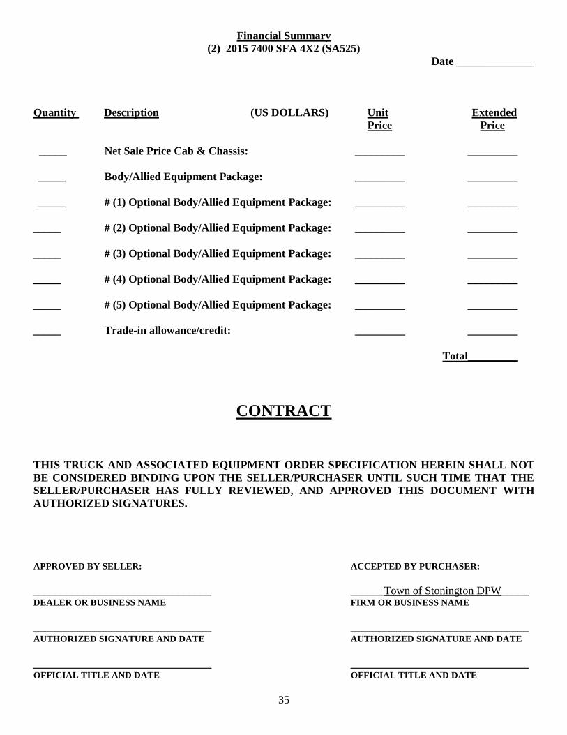
35
Financial Summary
(2) 2015 7400 SFA 4X2 (SA525)
Date ______________
Quantity Description (US DOLLARS) Unit Extended
Price Price
_____ Net Sale Price Cab & Chassis: _________ _________
_____ Body/Allied Equipment Package: _________ _________
_____ # (1) Optional Body/Allied Equipment Package: _________ _________
_____ # (2) Optional Body/Allied Equipment Package: _________ _________
_____ # (3) Optional Body/Allied Equipment Package: _________ _________
_____ # (4) Optional Body/Allied Equipment Package: _________ _________
_____ # (5) Optional Body/Allied Equipment Package: _________ _________
_____ Trade-in allowance/credit: _________ _________
Total_________
CONTRACT
THIS TRUCK AND ASSOCIATED EQUIPMENT ORDER SPECIFICATION HEREIN SHALL NOT
BE CONSIDERED BINDING UPON THE SELLER/PURCHASER UNTIL SUCH TIME THAT THE
SELLER/PURCHASER HAS FULLY REVIEWED, AND APPROVED THIS DOCUMENT WITH
AUTHORIZED SIGNATURES.
APPROVED BY SELLER: ACCEPTED BY PURCHASER:
________________________________ ______Town of Stonington DPW_____ DEALER OR BUSINESS NAME FIRM OR BUSINESS NAME
________________________________ ________________________________ AUTHORIZED SIGNATURE AND DATE AUTHORIZED SIGNATURE AND DATE
________________________________ ________________________________ OFFICIAL TITLE AND DATE OFFICIAL TITLE AND DATE
36
CONTACTS
Director of Finance: Maryanna Stevens Director of Public Works: Barbara McKrell
Phone: 860-535-5012 Phone: 860-535-5056
Fax: 860-535-0602 Fax: 860-535-1023
Address: Town of Stonington Address: Town of Stonington
Finance Office Department of Public Works
152 Elm Street 152 Elm Street
Stonington, CT. 06378 Stonington, CT. 06378
Highway Supervisor: Louis DiCesare II Master Mechanic: Steven Burdick
Phone: 860-535-5019 Phone: 860-535-5020
Fax: 860-535-1392 Fax: 860-535-1392
Address: Town of Stonington Address: Town of Stonington
Department of Public Works Department of Public Works
86 Alpha Ave 86 Alpha Ave
Stonington, CT. 06378 Stonington, CT. 06378