toxic use reduction - turi
TRANSCRIPT
Marl Girgenti (203) 287.1985 [email protected]
Toxic Use Reduction Institute Water Resource Conservation in Water
Treatment
What are we going to Discuss
• Review the process of water treatment and water
generation.
• Discuss means of reducing water consumption and
chemical generation in these systems
• Discuss reclamation of water and waste utilizing these
processes.
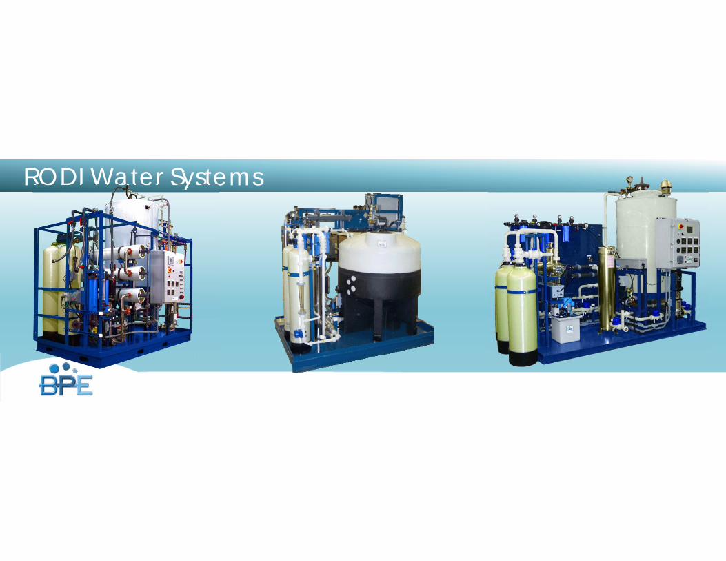
RODI Water Systems
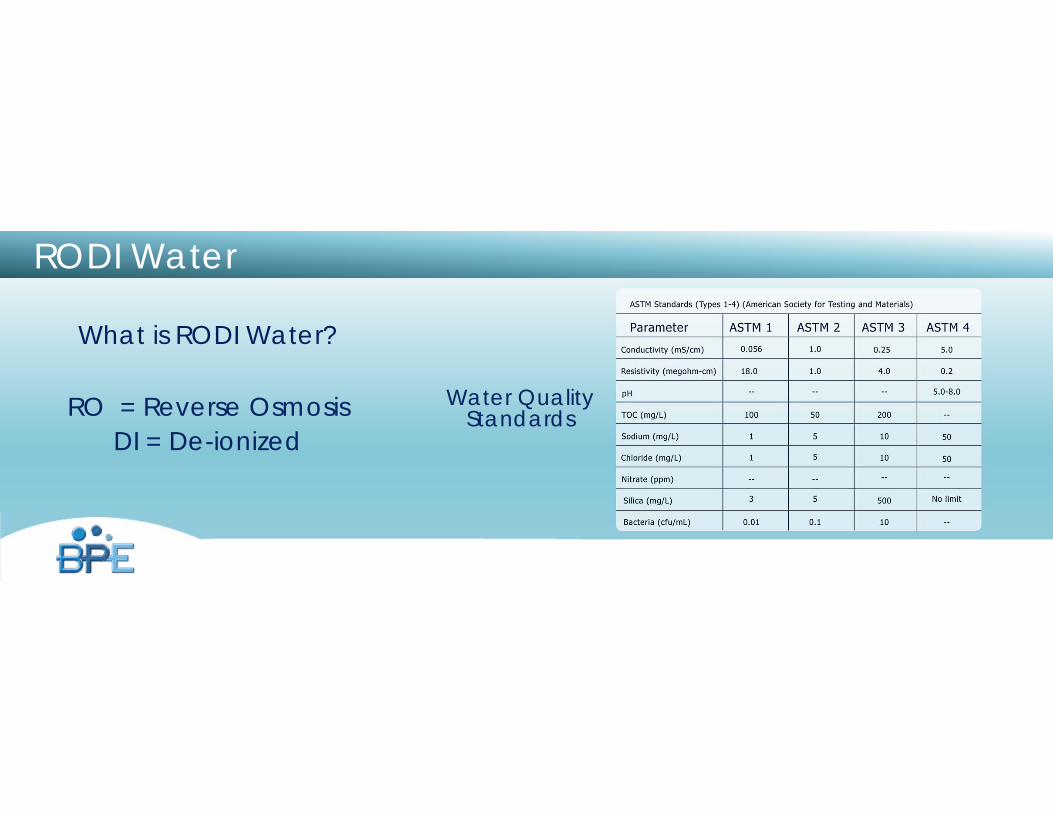
RODI Water
What is RODI Water?
RO = Reverse OsmosisDI = De-ionized
Water Quality Standards
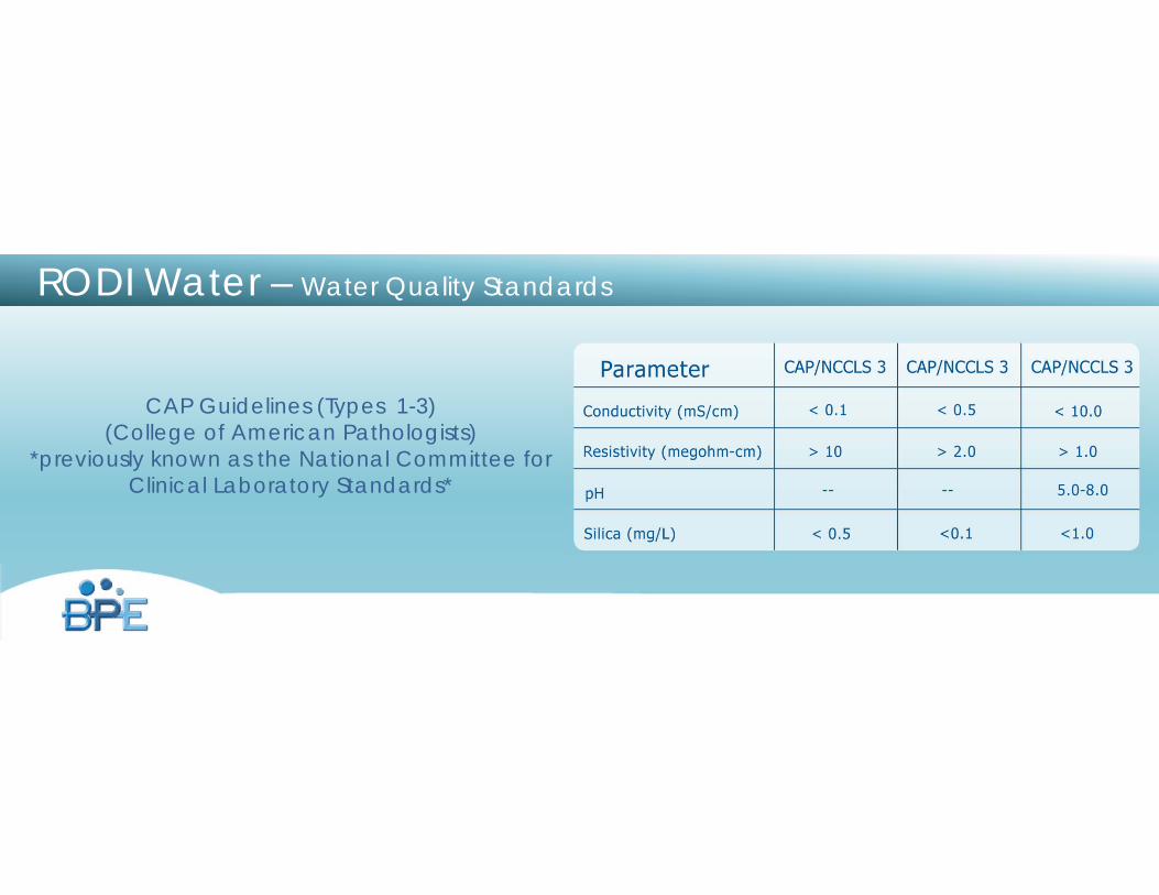
RODI Water – Water Quality Standards
CAP Guidelines (Types 1-3)(College of American Pathologists)
*previously known as the National Committee for Clinical Laboratory Standards*
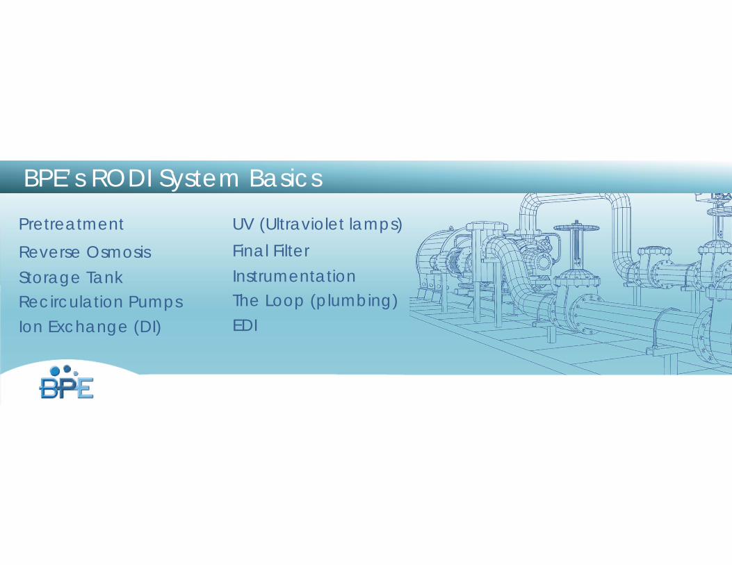
BPE’s RODI System Basics
PretreatmentReverse OsmosisStorage TankRecirculation PumpsIon Exchange (DI)
UV (Ultraviolet lamps)Final FilterInstrumentationThe Loop (plumbing)EDI
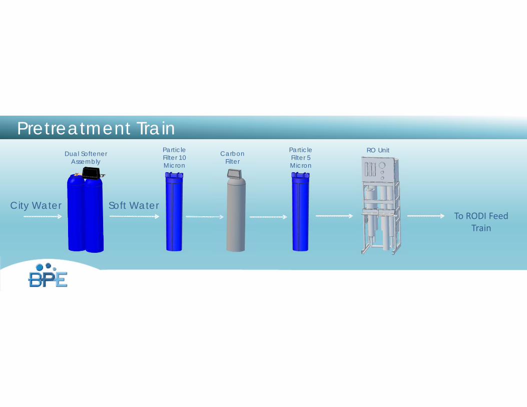
Pretreatment Train
City Water Soft Water
Dual Softener Assembly
Particle Filter 10 Micron
Carbon Filter
Particle Filter 5 Micron
RO Unit
To RODI Feed Train
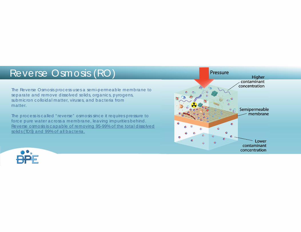
Reverse Osmosis (RO)The Reverse Osmosis process uses a semi-permeable membrane to separate and remove dissolved solids, organics, pyrogens, submicron colloidal matter, viruses, and bacteria from matter.
The process is called “reverse” osmosis since it requires pressure to force pure water across a membrane, leaving impurities behind. Reverse osmosis is capable of removing 95-99% of the total dissolved solids (TDS) and 99% of all bacteria.
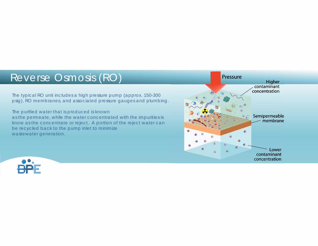
Reverse Osmosis (RO)The typical RO unit includes a high pressure pump (approx. 150-300 psig), RO membranes, and associated pressure gauges and plumbing.
The purified water that is produced is known as the permeate, while the water concentrated with the impurities is know as the concentrate or reject. A portion of the reject water can be recycled back to the pump inlet to minimize wastewater generation.

Reverse Osmosis (RO)
A good rule of thumb: For every one gallon of permeate produced, 2 gallons of incoming, pretreated water are required.
A two probe conductivity meter (one on the inlet to the RO and one on the permeate outlet) is used to measure the efficiency of the RO unit.
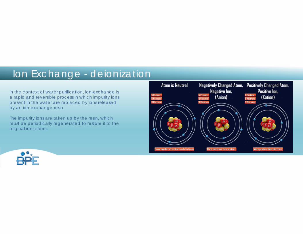
In the context of water purification, ion-exchange is a rapid and reversible process in which impurity ions present in the water are replaced by ions released by an ion-exchange resin.
The impurity ions are taken up by the resin, which must be periodically regenerated to restore it to the original ionic form.
Ion Exchange - deionization
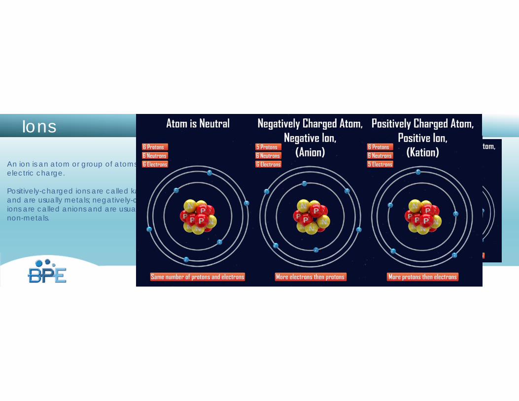
Ions
An ion is an atom or group of atoms with an electric charge.
Positively-charged ions are called kations and are usually metals; negatively-charged ions are called anions and are usually non-metals.
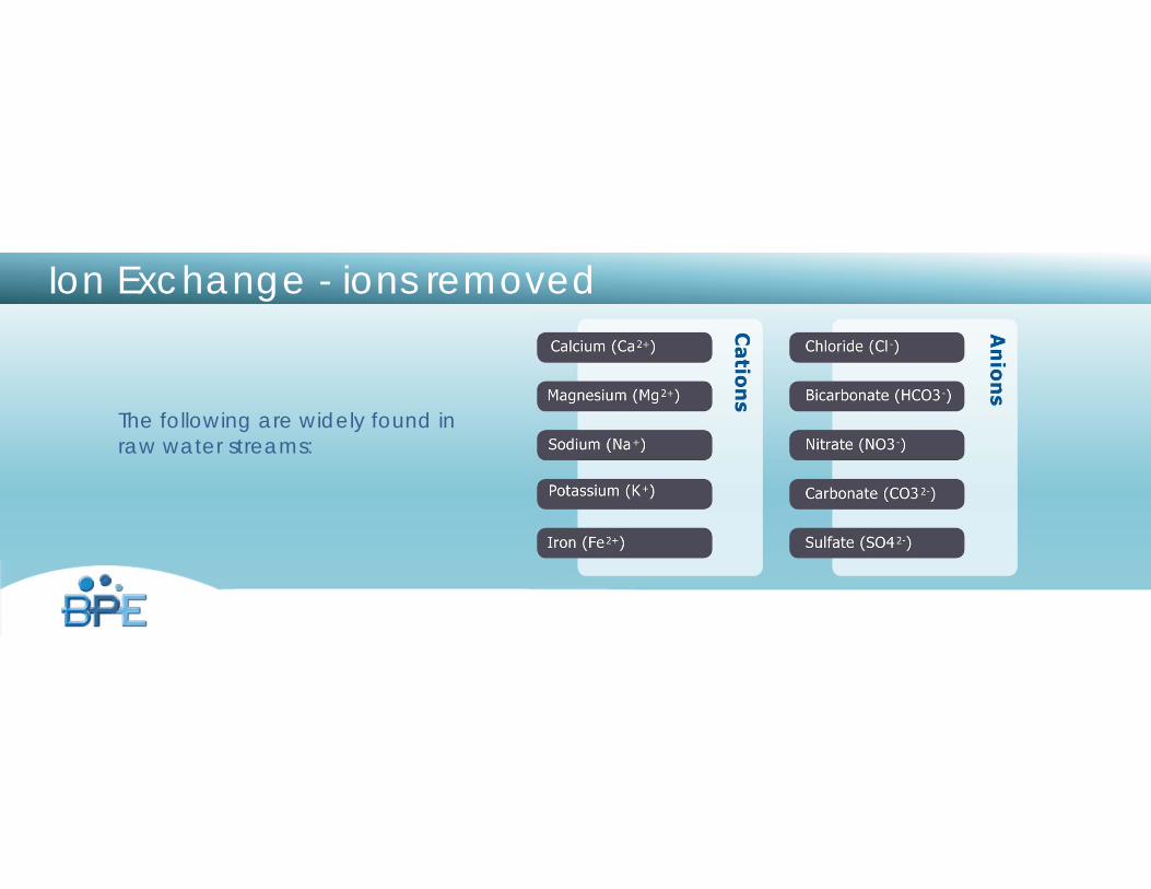
Ion Exchange - ions removed
The following are widely found in raw water streams:
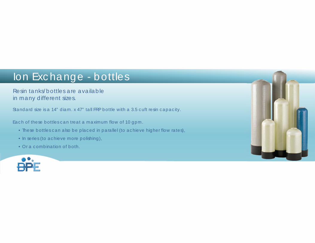
Ion Exchange - bottlesResin tanks/bottles are available in many different sizes.
Standard size is a 14” diam. x 47” tall FRP bottle with a 3.5 cuft resin capacity.
Each of these bottles can treat a maximum flow of 10 gpm.
• These bottles can also be placed in parallel (to achieve higher flow rates),
• In series (to achieve more polishing),
• Or a combination of both.
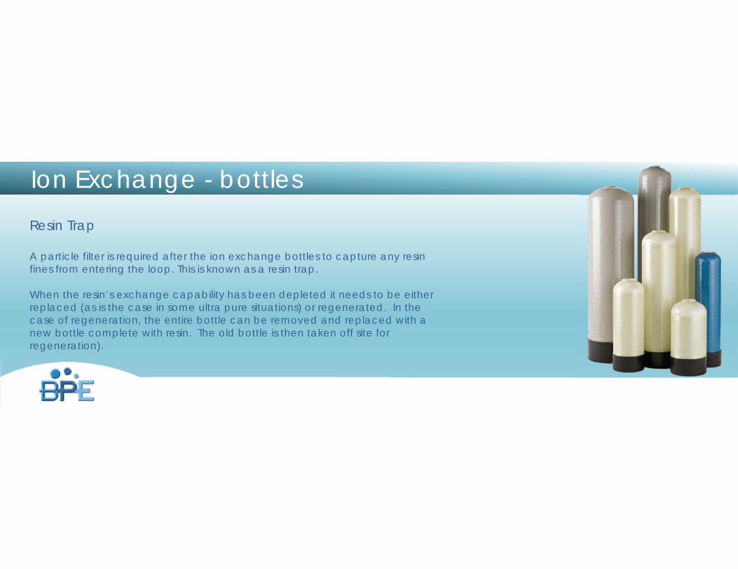
Ion Exchange - bottlesResin Trap
A particle filter is required after the ion exchange bottles to capture any resin fines from entering the loop. This is known as a resin trap.
When the resin’s exchange capability has been depleted it needs to be either replaced (as is the case in some ultra pure situations) or regenerated. In the case of regeneration, the entire bottle can be removed and replaced with a new bottle complete with resin. The old bottle is then taken off site for regeneration).
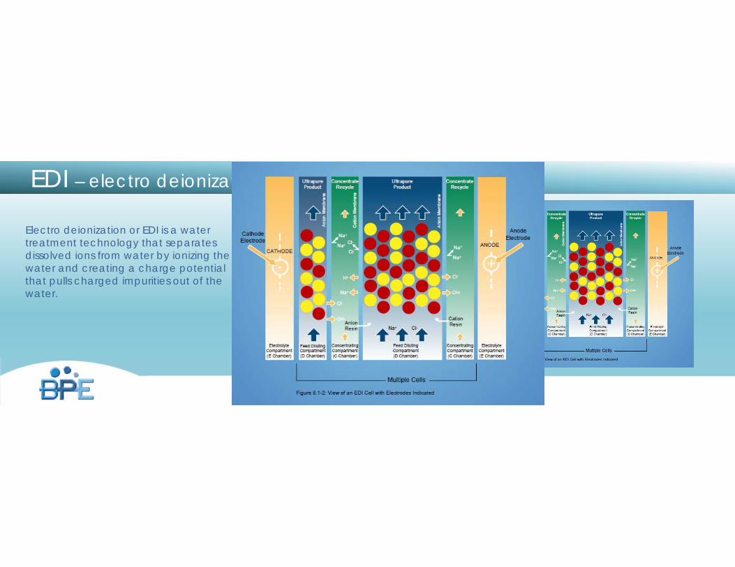
EDI – electro deionization
Electro deionization or EDI is a water treatment technology that separates dissolved ions from water by ionizing the water and creating a charge potential that pulls charged impurities out of the water.
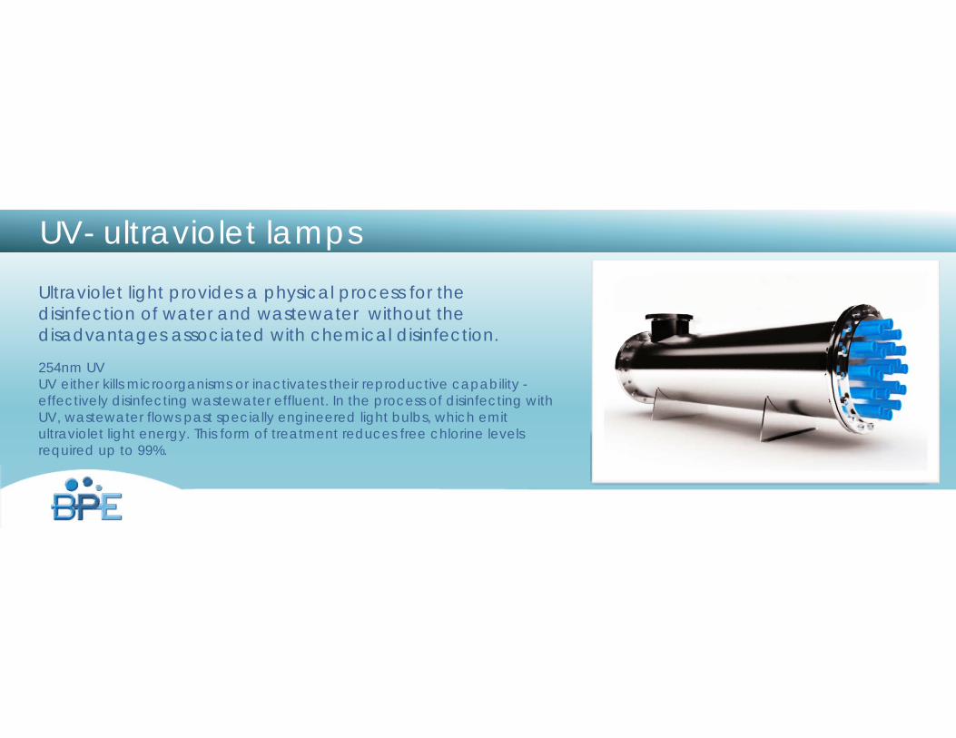
UV- ultraviolet lampsUltraviolet light provides a physical process for the disinfection of water and wastewater without the disadvantages associated with chemical disinfection.
254nm UVUV either kills microorganisms or inactivates their reproductive capability -effectively disinfecting wastewater effluent. In the process of disinfecting with UV, wastewater flows past specially engineered light bulbs, which emit ultraviolet light energy. This form of treatment reduces free chlorine levels required up to 99%.
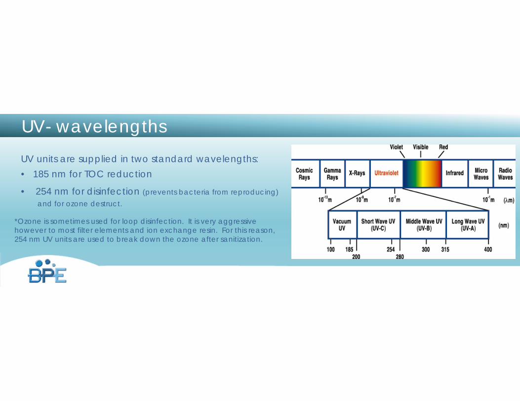
UV- wavelengthsUV units are supplied in two standard wavelengths:• 185 nm for TOC reduction
• 254 nm for disinfection (prevents bacteria from reproducing) and for ozone destruct.
*Ozone is sometimes used for loop disinfection. It is very aggressive however to most filter elements and ion exchange resin. For this reason, 254 nm UV units are used to break down the ozone after sanitization.
www.burtprocess.com
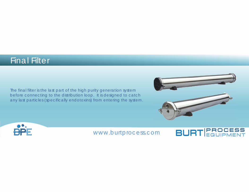
Final Filter
The final filter is the last part of the high purity generation system before connecting to the distribution loop. It is designed to catch any last particles (specifically endotoxins) from entering the system.
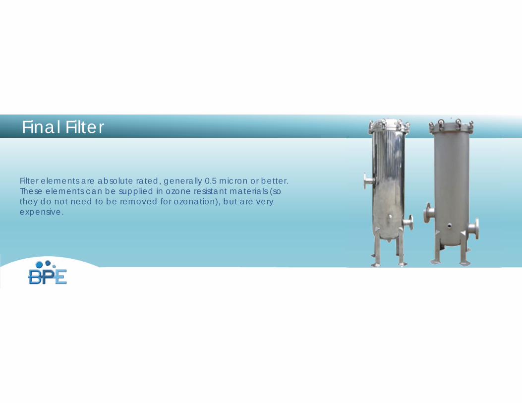
Final Filter
Filter elements are absolute rated, generally 0.5 micron or better. These elements can be supplied in ozone resistant materials (so they do not need to be removed for ozonation), but are very expensive.
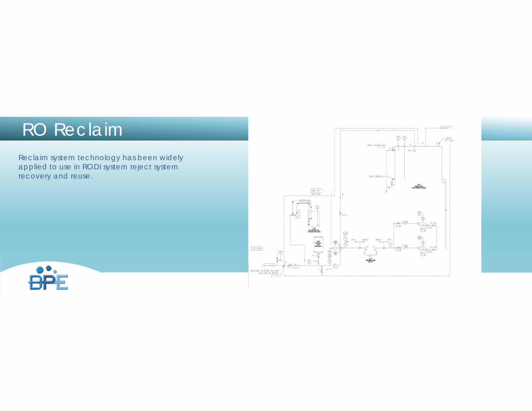
RO ReclaimReclaim system technology has been widely applied to use in RODI system reject system recovery and reuse.
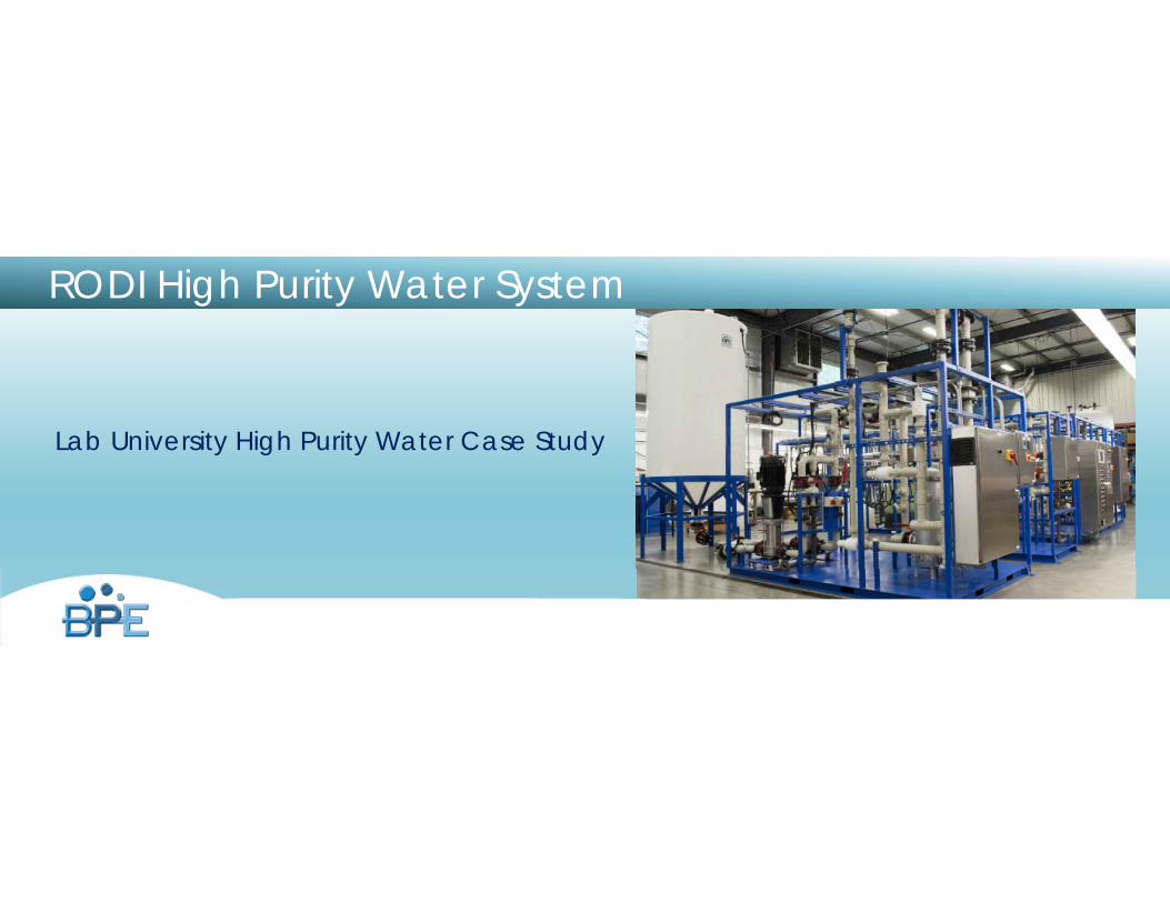
RODI High Purity Water System
Lab University High Purity Water Case Study
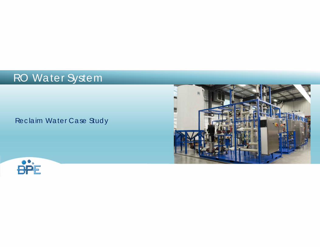
RO Water System
Reclaim Water Case Study
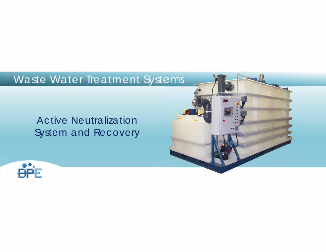
Active Neutralization System and Recovery
Waste Water Treatment Systems
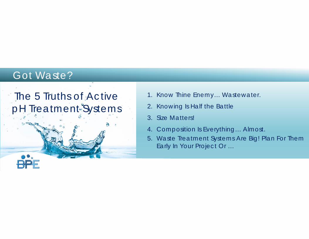
Got Waste?
The 5 Truths of Active pH Treatment Systems
1. Know Thine Enemy… Wastewater.
2. Knowing Is Half the Battle
3. Size Matters!
4. Composition Is Everything… Almost.5. Waste Treatment Systems Are Big! Plan For Them
Early In Your Project Or …
Wastewater
Truth # 1Know Thine Enemy…
Wastewater.
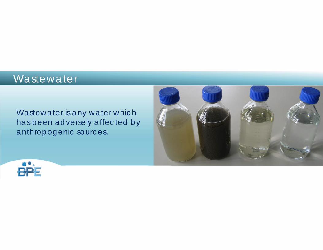
Wastewater is any water which has been adversely affected by anthropogenic sources.
Wastewater
www.burtprocess.com
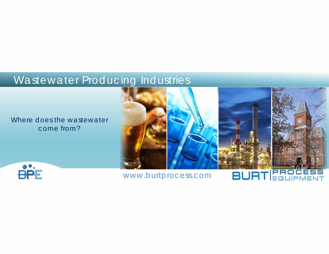
Where does the wastewater come from?
Wastewater Producing Industries
Understanding Wastewater
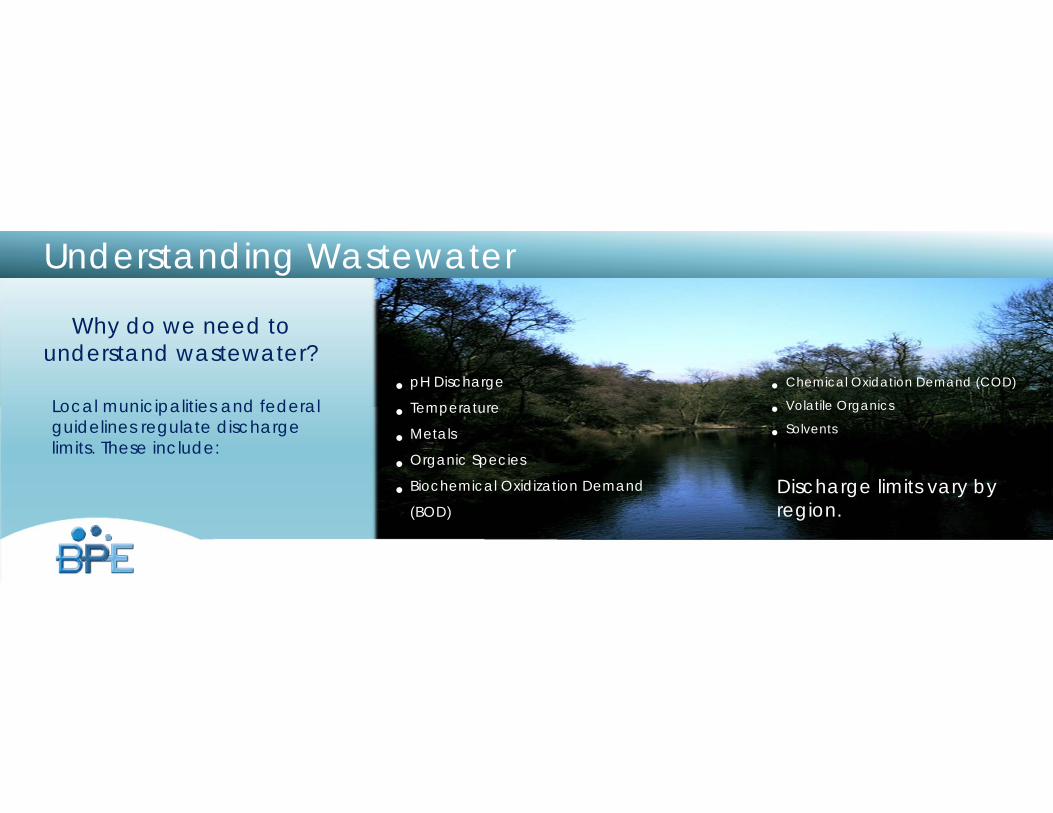
Why do we need to understand wastewater?
Local municipalities and federal guidelines regulate discharge limits. These include:
• pH Discharge
• Temperature
• Metals
• Organic Species
• Biochemical Oxidization Demand
(BOD)Discharge limits vary by region.
• Chemical Oxidation Demand (COD)
• Volatile Organics
• Solvents
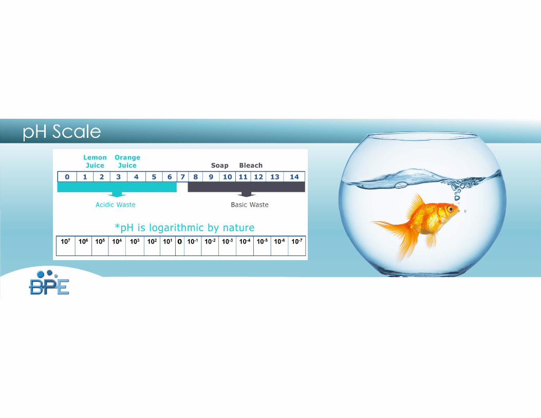
pH Scale
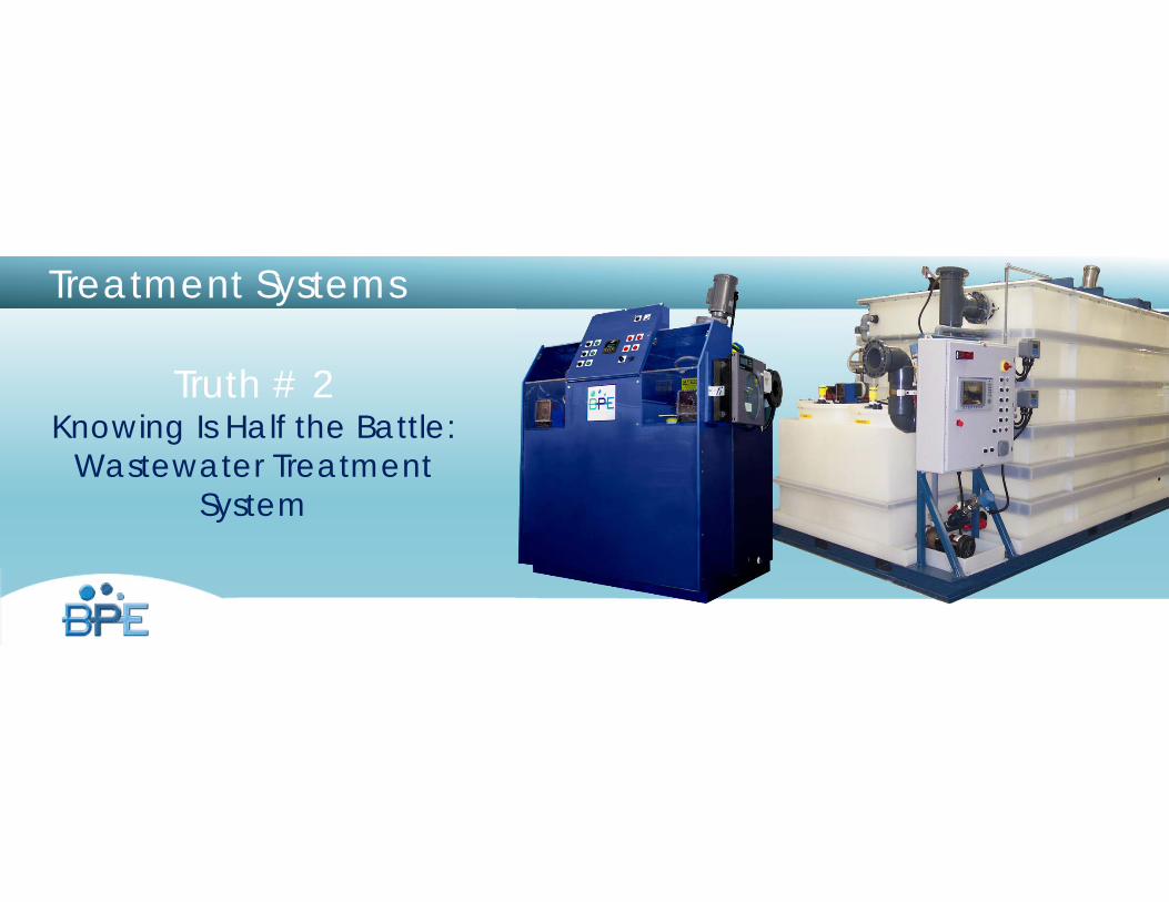
Treatment Systems
Truth # 2 Knowing Is Half the Battle:
Wastewater Treatment System
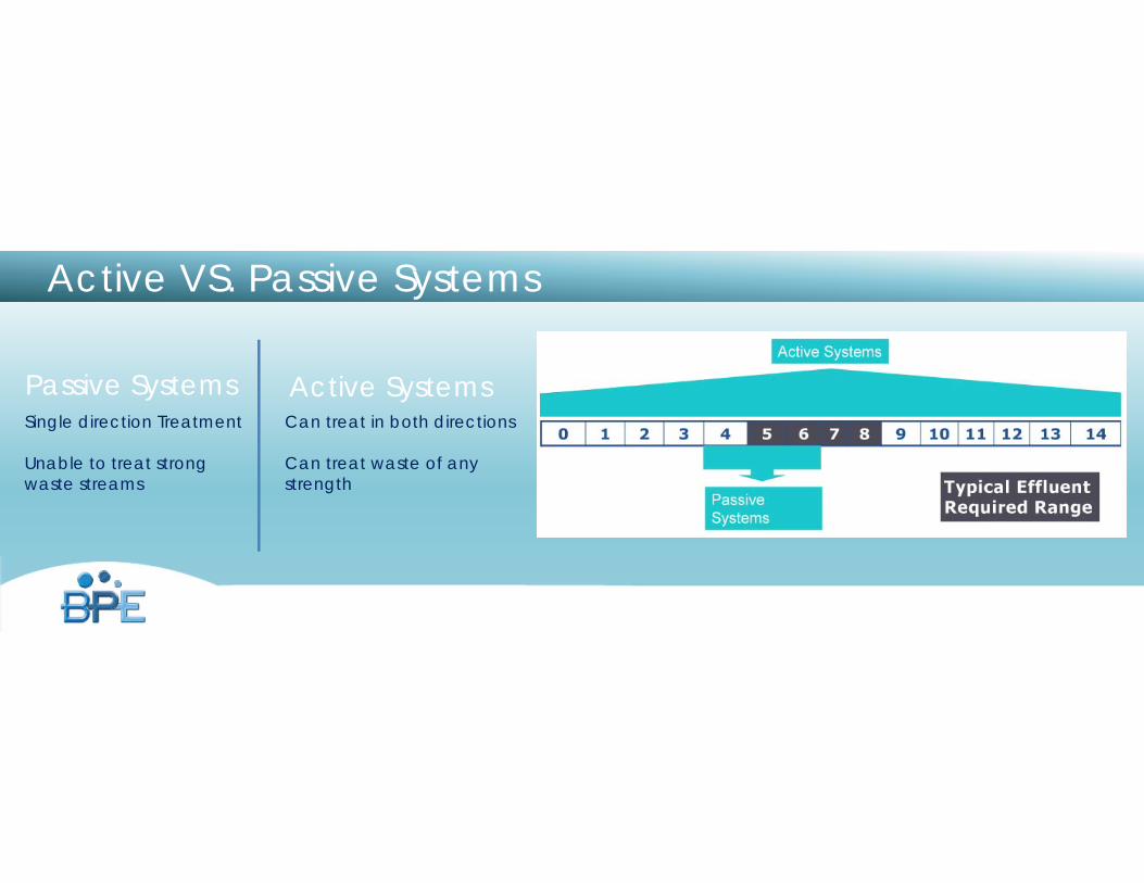
Active VS. Passive Systems
Active SystemsPassive SystemsSingle direction Treatment
Unable to treat strong waste streams
Can treat in both directions
Can treat waste of any strength
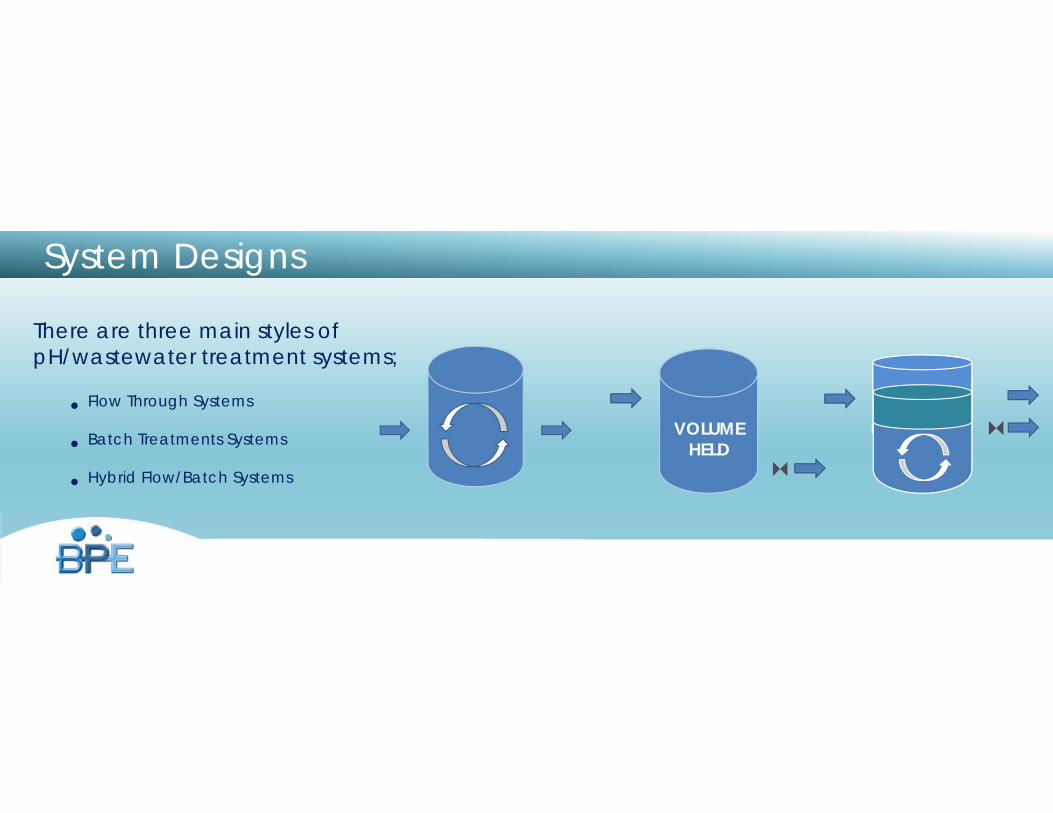
System Designs
There are three main styles of pH/wastewater treatment systems;
• Flow Through Systems
• Batch Treatments Systems
• Hybrid Flow/Batch Systems
VOLUME HELD
Additional Batch Volume
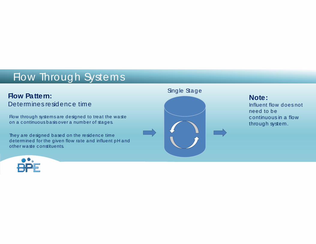
Flow Through Systems
Flow through systems are designed to treat the waste on a continuous basis over a number of stages.
They are designed based on the residence time determined for the given flow rate and influent pH and other waste constituents.
Flow Pattern:Determines residence time
Note:Influent flow does not need to be continuous in a flow through system.
Single Stage
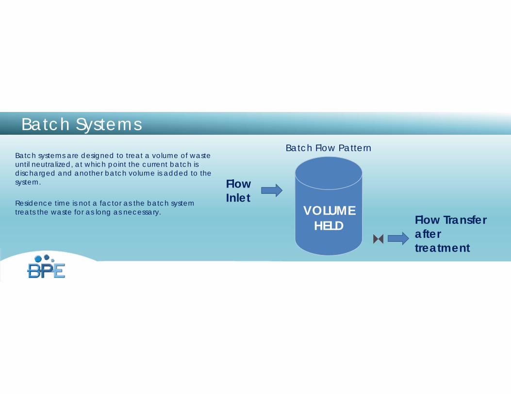
Batch SystemsBatch systems are designed to treat a volume of waste until neutralized, at which point the current batch is discharged and another batch volume is added to the system.
Residence time is not a factor as the batch system treats the waste for as long as necessary.
Flow Inlet
Flow Transferafter treatment
Batch Flow Pattern
VOLUME HELD
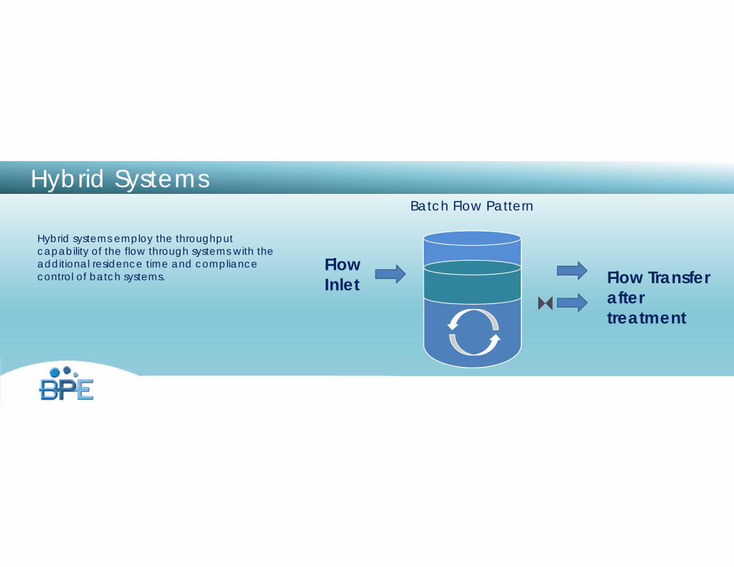
Hybrid Systems
Hybrid systems employ the throughput capability of the flow through systems with the additional residence time and compliance control of batch systems.
Flow Inlet Flow Transfer
after treatment
Batch Flow Pattern
Additional Batch Volume
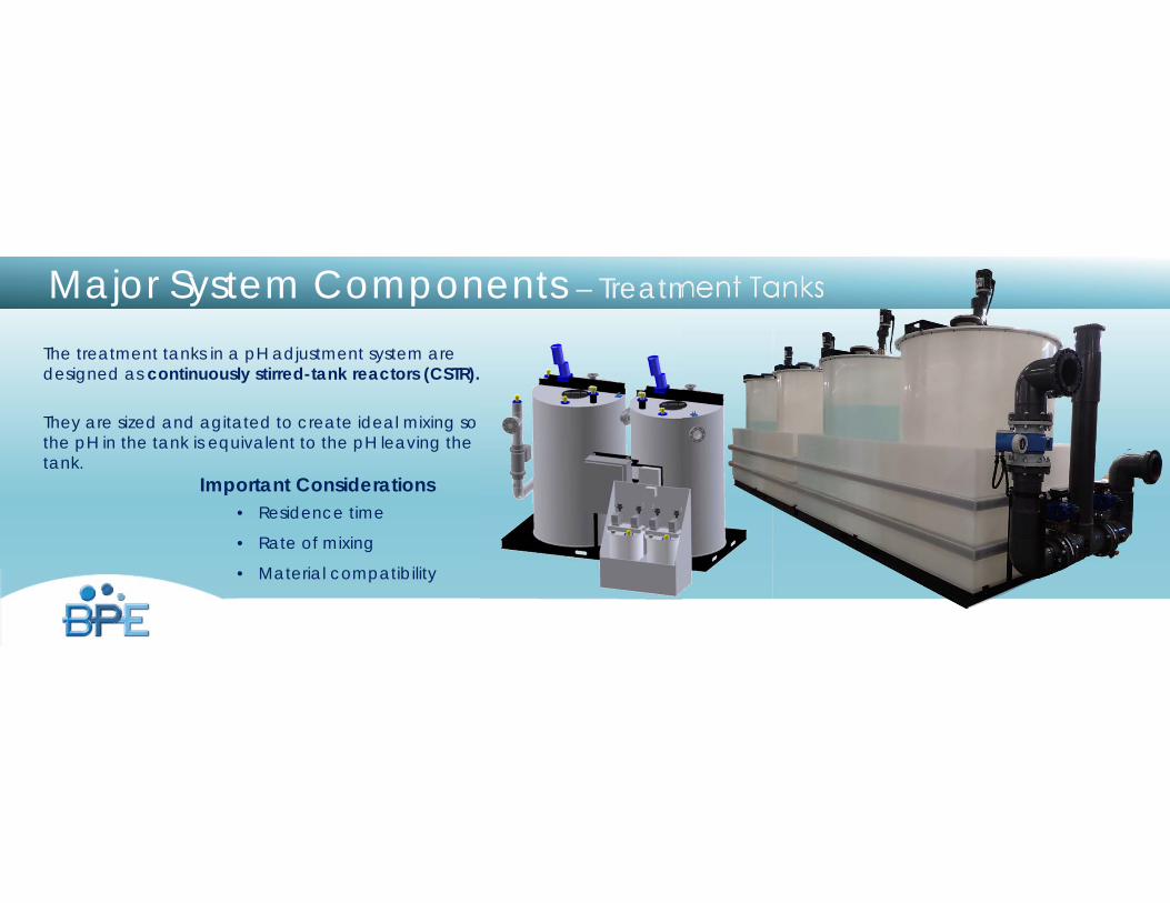
The treatment tanks in a pH adjustment system are designed as continuously stirred-tank reactors (CSTR).
They are sized and agitated to create ideal mixing so the pH in the tank is equivalent to the pH leaving the tank.
Major System Components – Treatment Tanks
Important Considerations• Residence time
• Rate of mixing
• Material compatibility
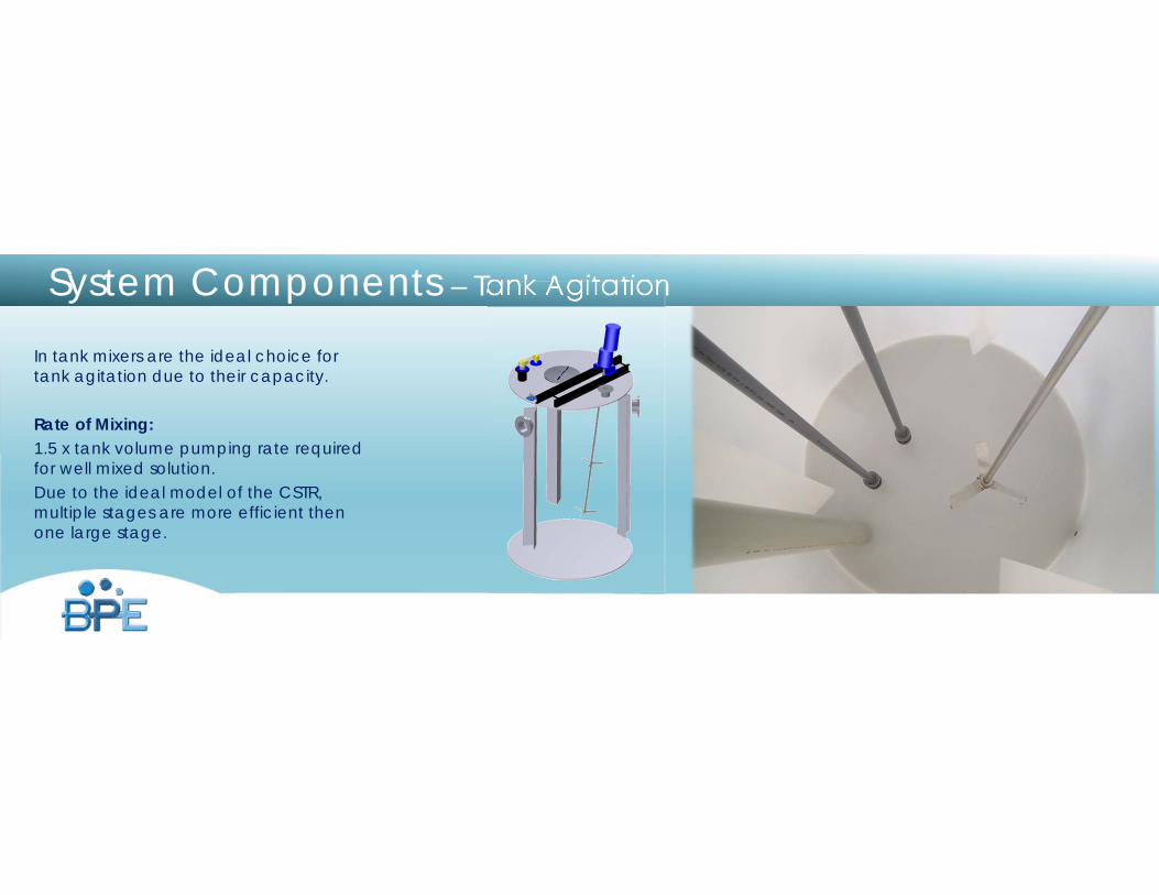
System Components – Tank Agitation
In tank mixers are the ideal choice for tank agitation due to their capacity.
Rate of Mixing:1.5 x tank volume pumping rate required for well mixed solution.Due to the ideal model of the CSTR, multiple stages are more efficient then one large stage.
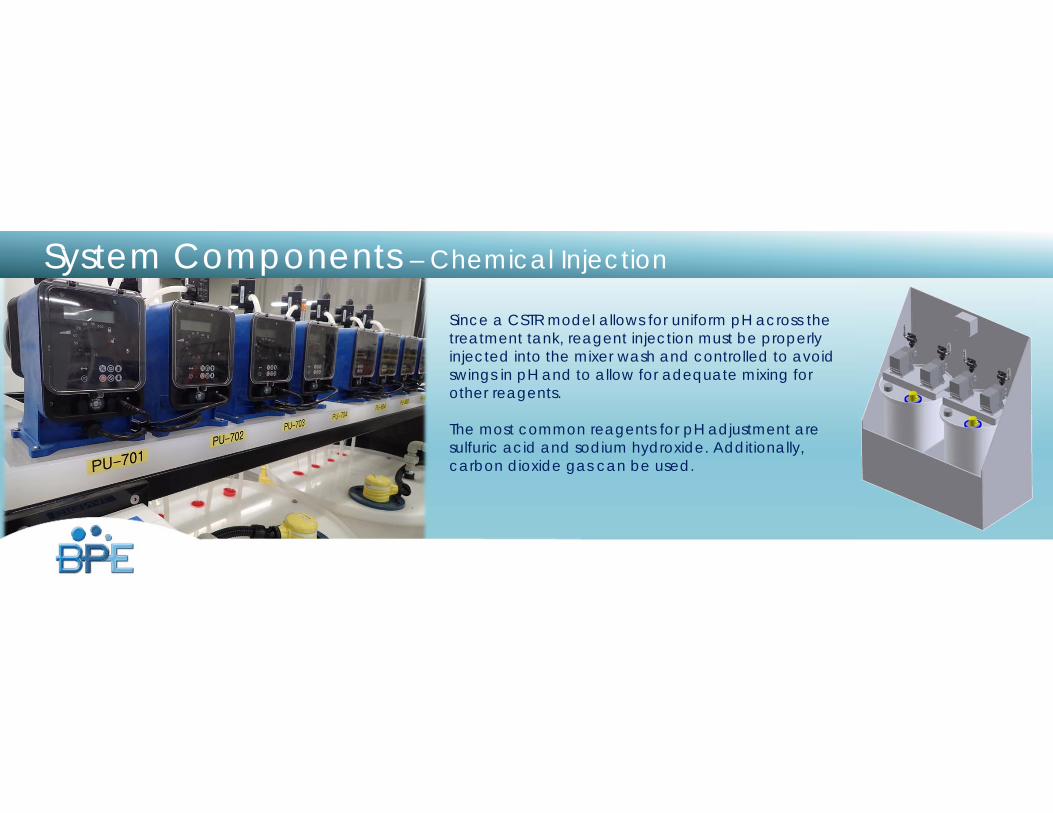
Since a CSTR model allows for uniform pH across the treatment tank, reagent injection must be properly injected into the mixer wash and controlled to avoid swings in pH and to allow for adequate mixing for other reagents.
The most common reagents for pH adjustment are sulfuric acid and sodium hydroxide. Additionally, carbon dioxide gas can be used.
System Components – Chemical Injection
www.burtprocess.com
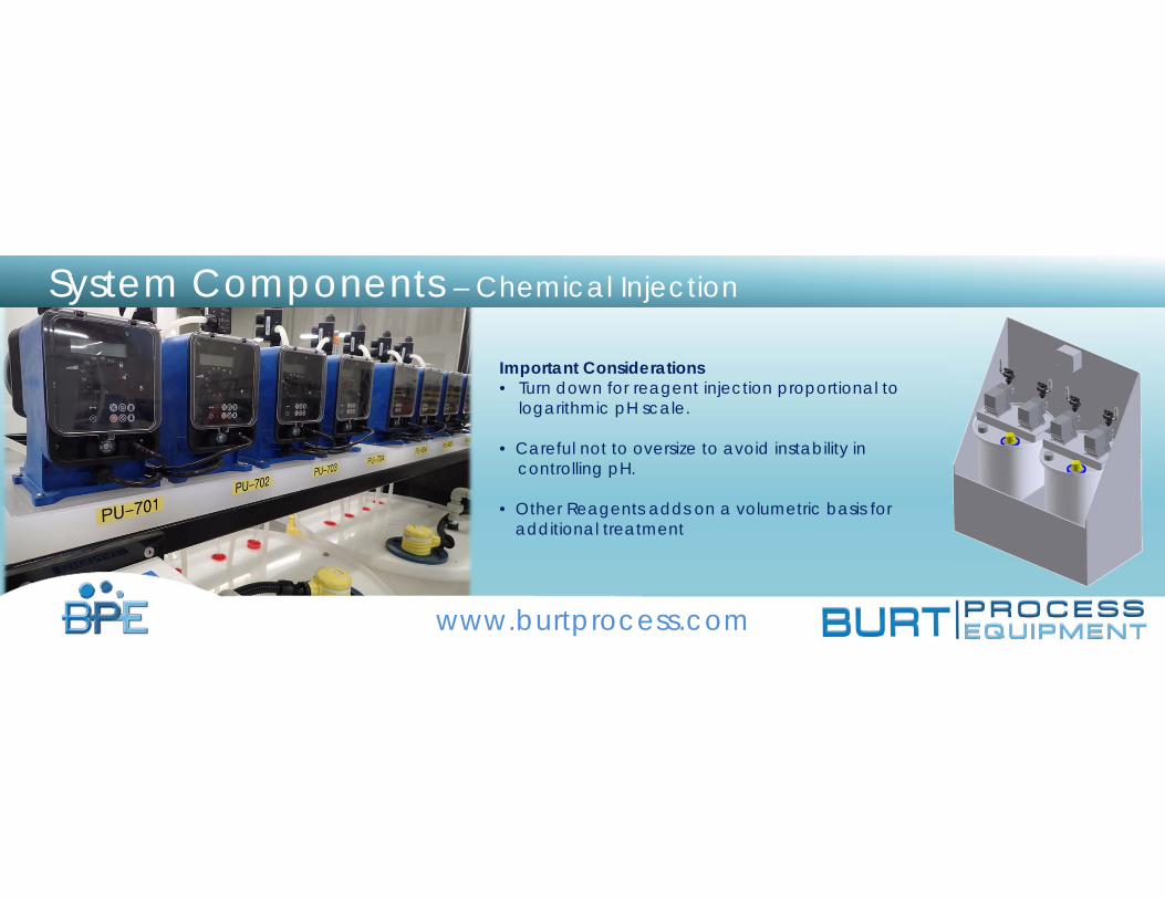
System Components – Chemical Injection
Important Considerations• Turn down for reagent injection proportional to
logarithmic pH scale.
• Careful not to oversize to avoid instability incontrolling pH.
• Other Reagents adds on a volumetric basis for additional treatment
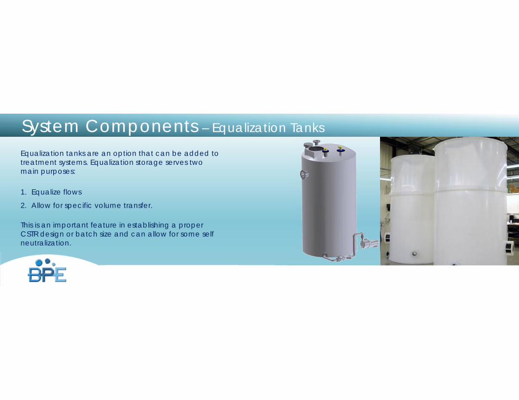
Equalization tanks are an option that can be added to treatment systems. Equalization storage serves two main purposes:
1. Equalize flows
2. Allow for specific volume transfer.
This is an important feature in establishing a proper CSTR design or batch size and can allow for some self neutralization.
System Components – Equalization Tanks
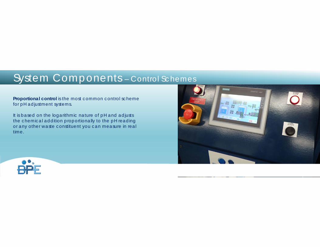
Proportional control is the most common control scheme for pH adjustment systems.
It is based on the logarithmic nature of pH and adjusts the chemical addition proportionally to the pH reading or any other waste constituent you can measure in real time.
System Components – Control Schemes
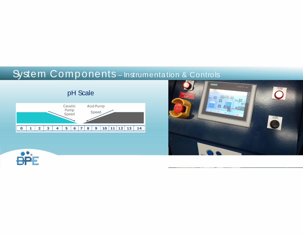
pH Scale
System Components – Instrumentation & Controls
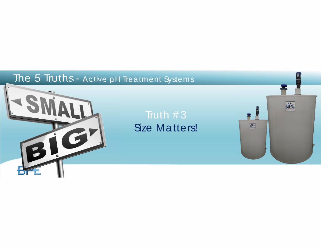
The 5 Truths - Active pH Treatment Systems
Truth #3Size Matters!
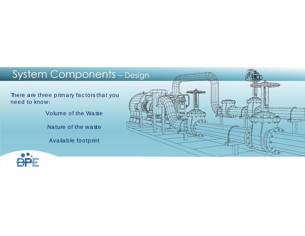
System Components – Design
There are three primary factors that you need to know:
Volume of the Waste
Nature of the waste
Available footprint
System DesignVolume Determinations
Determining the waste volume is critical in system selection.
Batch System Sizing
Batch systems require influent waste to be transferred to the system in predetermined volumes and then held for treatment. As such, any batch system can only be run in controlled volume conditions or with an up-front equalization tank.
System DesignVolume Determinations
Determining the waste volume is critical in system selection.
Batch System Sizing
To size a batch system you need to know the exact flow profile and volumes of your waste streams as well as have the foot print to support the holding tanks that will be required for the system to function properly.
Sizing Flow through Systems
Flow through systems can handle waste of any flow rate but to size the system one must determine the maximum flow rate the system can see at any time.
To do this, values have to be assigned to individual devices that will be connected to the system.
System Design
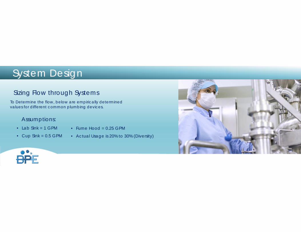
To Determine the flow, below are empirically determined values for different common plumbing devices.
Assumptions:• Lab Sink = 1 GPM
• Cup Sink = 0.5 GPM
System Design
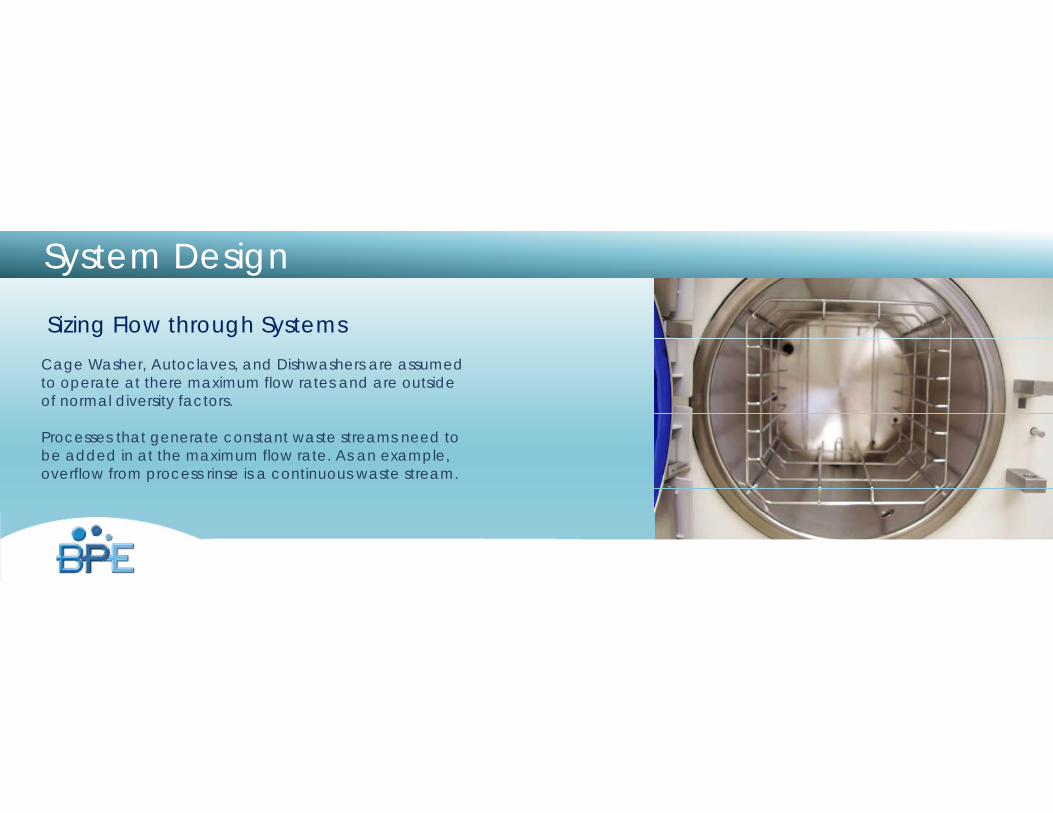
Sizing Flow through Systems
• Fume Hood = 0.25 GPM
• Actual Usage is 20% to 30% (Diversity)
System Design
Sizing Flow through SystemsCage Washer, Autoclaves, and Dishwashers are assumed to operate at there maximum flow rates and are outside of normal diversity factors.
Processes that generate constant waste streams need to be added in at the maximum flow rate. As an example, overflow from process rinse is a continuous waste stream.
Truth #4Composition Is Everything…
Almost.
The 5 Truths - Active pH Treatment Systems
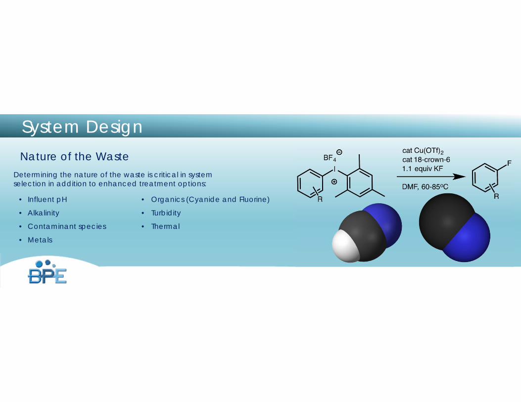
Nature of the WasteDetermining the nature of the waste is critical in system selection in addition to enhanced treatment options:
System Design
• Organics (Cyanide and Fluorine)
• Turbidity
• Thermal
• Influent pH
• Alkalinity
• Contaminant species
• Metals
System Design
Nature of the Waste Influent pH
Influent pH dictates the number of stages for flow through systems and batch times for batch systems.
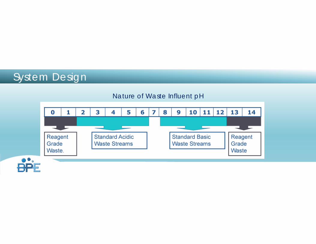
Nature of Waste Influent pH
System Design
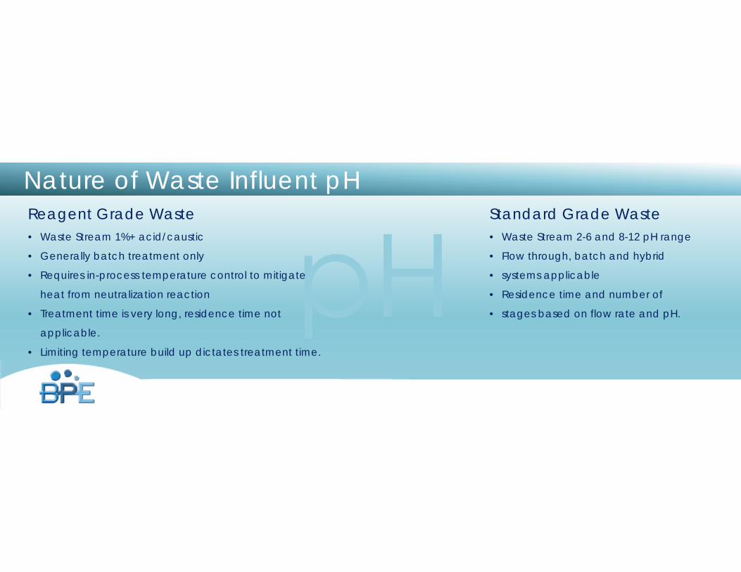
Reagent Grade Waste• Waste Stream 1%+ acid/caustic
• Generally batch treatment only
• Requires in-process temperature control to mitigate
heat from neutralization reaction
• Treatment time is very long, residence time not
applicable.
• Limiting temperature build up dictates treatment time.
Standard Grade Waste• Waste Stream 2-6 and 8-12 pH range
• Flow through, batch and hybrid
• systems applicable
• Residence time and number of
• stages based on flow rate and pH.
Nature of Waste Influent pH
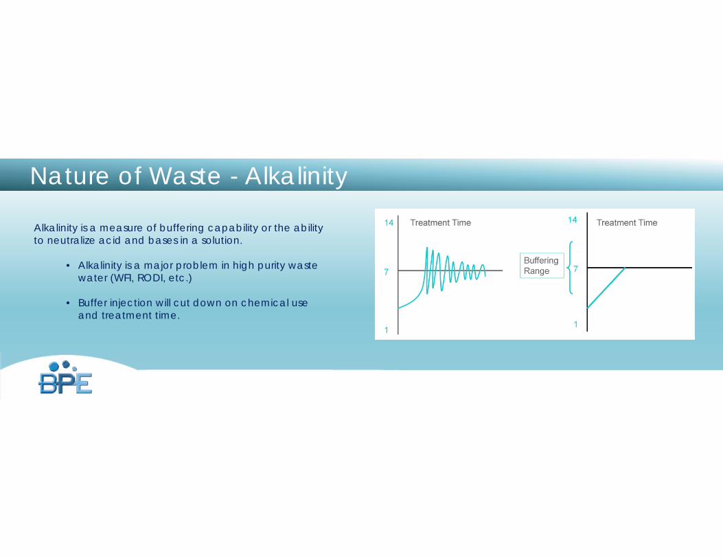
Nature of Waste - Alkalinity
Alkalinity is a measure of buffering capability or the abilityto neutralize acid and bases in a solution.
• Alkalinity is a major problem in high purity waste water (WFI, RODI, etc.)
• Buffer injection will cut down on chemical use and treatment time.
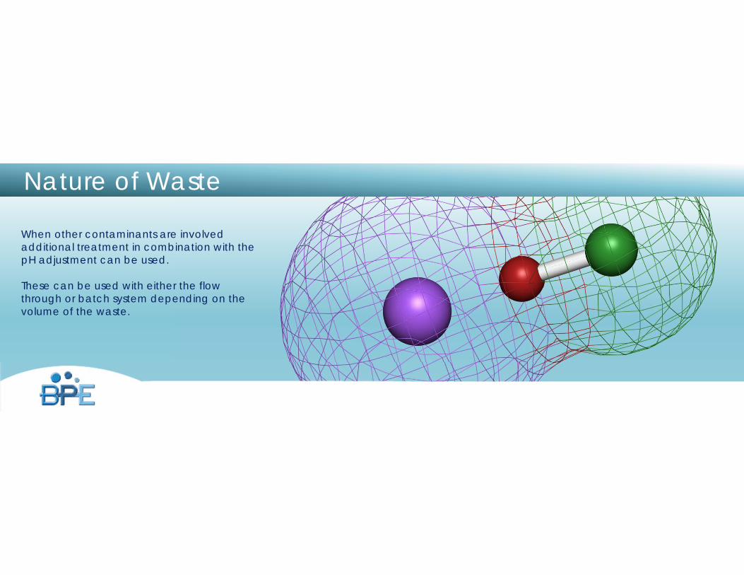
Nature of Waste
When other contaminants are involved additional treatment in combination with the pH adjustment can be used.
These can be used with either the flow through or batch system depending on the volume of the waste.
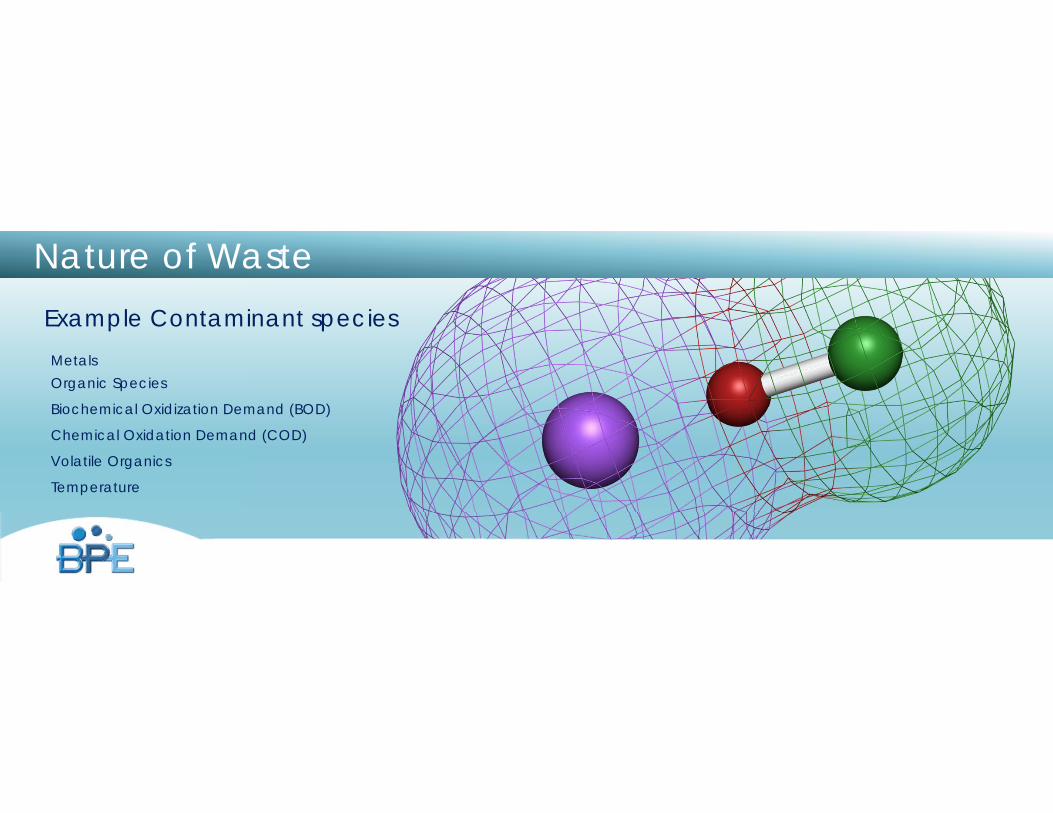
Nature of WasteExample Contaminant speciesMetalsOrganic Species
Biochemical Oxidization Demand (BOD)
Chemical Oxidation Demand (COD)
Volatile Organics
Temperature

System DesignAdditional Treatment Options
• Membrane Treatment
• Ion Exchange
• Precipitation
• Destruct Systems
Truth #5Waste Treatment
Systems Are Big! Plan For Them Early In Your
Project Or …
The 5 Truths - Active pH Treatment Systems
pH System Video
Putting It All Together - Case Studies

www.burtprocess.com
Thank You.Any Questions?