tpv 4300 - ponar-wadowice.pl6182,tpv+4300.pdf · axial piston pump tpv 4300 the production line of...
TRANSCRIPT

Variable Displacement Closed Loop System Axial Piston Pump
TPV 4300
THE PRODUCTION LINE OF PONAR WADOWICE
PONAR Wadowice S.A.ul. Wojska Polskiego 29 34-100 WadowiceTel.: +48 33 488 21 00Fax: +48 33 488 21 03E-mail: [email protected]: www.ponar-wadowice.pl


Pag. 3
Variable Displacement Axial Piston PumpTPV 4300
INDEX
General information......................................................................................Technical specifications................................................................................System design parameters...........................................................................Performance diagram...................................................................................Installation instructions..................................................................................Hydraulic fluid...............................................................................................Hydraulic fluid filtration..................................................................................
TPV 4300Order code...................................................................................................General dimensions/pump ports...................................................................Shaft option and mounting flanges...............................................................SHI Hydraulic servo control...........................................................................SEI 1.3 - 2.3 Electro-proportional servo control............................................SEI 1.3D - 2.3D Electro-proportional servo control.......................................Rear pump mounting flanges........................................................................OPTIONAL SB Screw by-pass ....................................................................OPTIONAL MOB Man on board....................................................................
TPVT 4300Order code...................................................................................................General dimensions/Tandem pump ports.....................................................SHI Hydraulic servo control...........................................................................SEI 1.3 - 2.3 Electro-proportional servo control............................................SEI 1.3D - 2.3D Electro-proportional servo control.......................................Rear pump mounting flanges........................................................................OPTIONAL SB Screw by-pass ....................................................................OPTIONAL MOB Man on board....................................................................
Trouble shooting...........................................................................................Accessories...................................................................................................
56789 - 101112
14 - 15161718 - 1920 - 2223 - 2526 - 27 2829 - 30
32 - 333435 - 3637 - 3940 - 4243 - 444546 - 47
4849


Pag. 5
Variable Displacement Axial Piston PumpTPV 4300
GENERAL INFORmATION
● The new TPV-TPVT 4300 are variable di-splacement axial piston pumps with swash-plate system, for closed loop hydrostatic transmissions, that offer the best power to weight ratio because of new innovative de-sign and production technologies.
● The flow rate is proportional to the rotation speed and is continuously variable accor-ding to the angle of the swash-plate from "0" to maximum displacement.
● The TPV-TPVT 4300 is equipped with a bo-ost pump, “gerotor” type of new design and high efficiency to keep the circuit pressuri-sed, to compensate the oil leakages of the hydrostatic transmission, to avoid cavitation of the piston pump and to supply low pres-sure oil flow to the remote controls of the pumps and of the hydraulic transmission (max 3 MPa).
● Different types of hydraulic or electro-pro-portional controls are available for remote regulation of the pump displacement by me-ans of hydraulic or electric joysticks.The mounting flange is according to SAE-B 2 bolt, the through-drive is according SAE-A 2 bolt.Different other optionals are available for the TPV-TPVT 4300.
● The piston pumps are to be considered as individual components for the purposes of Directive 98/37/EC, therefore have been built to be integrated into a circuit or to be assembled with other components to form a machine or system. They can be opera-ted only after they have been installed in the machine/system which they are inten-ded for.
● The TPV-TPVT 4300 pumps must be used to create, manage and regulate oil flow in a closed loop system. Any other use should
be considered improper.
● The pumps are built according to the techno-logy normally used for this type of product.There is the risk of injury or damage to personnel during their installation and use if you do not respect the normal safety in-structions or if used by untrained personnel.

Variable Displacement Axial Piston PumpTPV 4300
Pag. 6
PUmP mODEL TPV32
TPV38
TPV45
TPV50
Theorical max. displacement cm3/n 32 38 45 50
Flow rating(1) I/min 115 137 162 180Power rating(1) kW 48 57 67,5 75Boost pump displacement cm3/n 14Rated pressure MPa 28Max. pressure MPa 32Boost pressure(2) MPa 1,5-2,6Absolute suction pressure(3) MPa > = 0,08Max. case pressure MPa 0,15
Minimum speed n/min 700
Rated speed n/min 3.600Max. speed n/min 3.900Max. fluid temperature °C 80Fluid viscosity cSt 15-35Fluid contamination 19/17/14 ISO 4406 (NAS 8)Mass (single pump with hydr-servo) kg 24Mass (tandem pump with hydr-servo) kg 49,5
(1) [V max -η max] (2) 1.500 n/min (3) v <= 30mm2/s
The housing and the distributor of the pumps TPV-TPVT 4300 are made in cast iron. The flow rate is proportional to the rotation speed and the displacement is continuously variable. It increases as the swash-plate an-gle moves from "0" to maximum position.If the swash-plate is positioned out of the neu-tral position, the flow respectively follows one of the two directions.
Key features● compact design● integrated optionals● high power to weight ratio ● low noise integrated boost pump
Typical applications● construction equipments● green mowers● zero turn machines● agricultural machines● utility vehicles ● forest vehicles● logistic machines
TECHNICAL SPECIFICATIONS
Pag. 7
Variable Displacement Axial Piston PumpTPV 4300
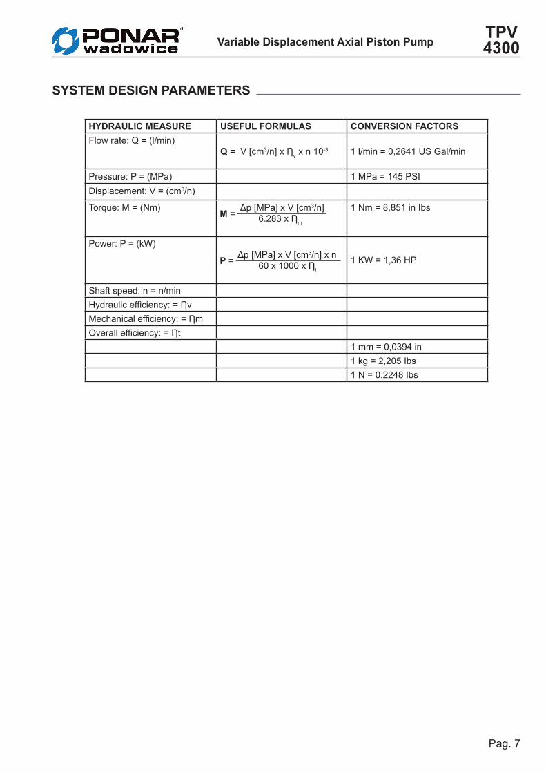
SYSTEm DESIGN PARAmETERS
HYDRAULIC mEASURE USEFUL FORmULAS CONVERSION FACTORSFlow rate: Q = (l/min)
Q = V [cm3/n] x Ƞv x n 10-3 1 l/min = 0,2641 US Gal/min
Pressure: P = (MPa) 1 MPa = 145 PSIDisplacement: V = (cm3/n)
Torque: M = (Nm) Δp [MPa] x V [cm3/n] 6.283 x Ƞm
1 Nm = 8,851 in Ibs
Power: P = (kW) Δp [MPa] x V [cm3/n] x n 60 x 1000 x Ƞt
1 KW = 1,36 HP
Shaft speed: n = n/minHydraulic efficiency: = ȠvMechanical efficiency: = ȠmOverall efficiency: = Ƞt
1 mm = 0,0394 in1 kg = 2,205 Ibs1 N = 0,2248 Ibs
m =
P =

Variable Displacement Axial Piston PumpTPV 4300
Pag. 8
Power at 28 mPa (max. displacement)
Output Flow at 28 mPa (max. displacement)
Speed n/min.
Speed n/min.
Pow
er k
WO
utpu
t Flo
w l/
min
.
0,00
20,00
40,00
60,00
80,00
100,00
120,00
140,00
160,00
0 500 1000 1500 2000 2500 3000 3500 4000
TPV-32
TPV-38
TPV-45
TPV-50
DIAGRAMMA P-n°giri (280 bar)
0,00
10,00
20,00
30,00
40,00
50,00
60,00
70,00
80,00
0 500 1000 1500 2000 2500 3000 3500 4000
n° giri/min.
Pote
nza
[kW
]
TPV-32
TPV-38
TPV-45
TPV-50
PERFORmANCE DIAGRAm
Performance diagrams● The diagrams show the data of maximum
speed and maximum continues pressure.● Data may vary depending on pump displa-
cement.
Pressure● Continuous pressure: is the average pres-
sure for continuous work, which must not be exceeded, to ensure a correct and long lasting service of the pump.
● Maximum pressure: is the maximum allow-able pressure for short periods and must never be exceeded.
Speed● Continuous work speed: is the maximum
recommended speed for continuous opera-tion of the pump under full load.
● Maximum speed: is the maximum permis-sible speed for the pump for short periods and not fully loaded. The use of the pump with this speed can reduce the life and cau-se a loss of power or of the hydrostatic bra-king capacity.
CautionAny damage caused to the pump can reduce or eliminate the hydrostatic braking capacity. It is therefore necessary to provide an auxi-liary braking system capable of stopping and supporting the weight of the complete machi-ne, in the event of loss of hydrostatic power.

Pag. 9
Variable Displacement Axial Piston PumpTPV 4300
Standards for the installation, start up and maintenance● When mounting the pump above the mini-
mum level of the tank, distance of the hi-ghest point of the pump over the oil level MUST NOT exceed 250 mm.
● To reduce the noise level typical of all piston pumps we recommend:- use hoses instead of pipes- limit to a minimum the length of eventual pipes- fix rigid pipe sections with special supports
equipped with rubber vibration dampening devices
- use pipes and hoses with a diameter ac-cording to the speed values below:
Suction line = 0,6 ÷ 1,2 m / s Drain = 1,5 ÷ 3,6 m / s Pressurized lines = max 6 m / s
● To calculate the speed of the oil in the lines refer to the formula below:
V = Q * 21,22 / D V = speed (m/s) Q = flow rate (l/min) D = internal pipe/hose diameter (mm)
● In any case NEVER use pipes/hoses or fit-tings with diameter smaller than that of the corresponding ports on the pump. This in-dication is ABSOLUTELY OBLIGATORY for the drain line to avoid to pressurize the pump housing and extrude the lip seal of the pump shaft.
● During mounting cure the alignment of the pump, concentric with the drive shaft sleeve to prevent overloading of the bearing. See page 10.
● For the hydraulic system, we recommend using pipes/hoses washed internally with hydraulic oil or, even better, with solvent.
● Special care must be taken when cleaning the inside of the tank (painting is recom-mended after sand blasting).
● To improve the functionality of the boost pump, it is recommended to place it below minimum tank level.
● The pumps can be installed in any direction and position. For further information contact our Techni-cal Department.
INSTALLATION INSTRUCTIONS

Variable Displacement Axial Piston PumpTPV 4300
Pag. 10
(continued) INSTALLATION INSTRUCTIONS
Shaft CouplingTo connect the pump shaft to the engine flywheel or electric motor shaft use a flexible
ΔY ±
0.05
Δα°±30'
coupling. The alignment must be within the tolerances indicated in the figures above. For an optimal function of the pump the shaft should not be subjected to radial or axial lo-ads. During the installation or removal, do not force the coupling of the pump shaft, but always use the threaded hole on the shaft.
Start up● Before starting fill the tank and the other
components with new filtered oil. You should run a flushing of the complete hydraulic sy-stem (see Use and Maintenance Manual). Check that the low pressure value is cor-rect (refer to the Use and Maintenance Ma-nual).
● Restore the oil level in the tank.
maintenance● The first oil change should be made after
500 hours of operation. Later change the oil every 2000 hours.
● The first replacement of the filter cartridge has to be made after 50 hours for a prelimi-nary circuit cleaning. Then after further 500 hours.
● These frequencies have to be reduced in the case where the indicator shows the clogging of the filter cartridge and in case of operation in environments with a high level
of contamination.
CAUTION● Always work with the utmost attention to the
moving parts; do not use loose or fluttering clothing.
● Do not approach rotating wheels, tracks, chains or shafts if not properly protected, or when they may start moving without notice.
● Do not loosen or disconnect fittings and pi-pes/hoses while the engine is running.
● Avoid oil leaks in order to prevent envi-ronmental pollution.
Load capacity of rear shaft (through drive shaft)● The rear shaft is not able to carry radial
loads.
!

Pag. 11
Variable Displacement Axial Piston PumpTPV 4300
ViscosityThe maximum duration and the maximum ef-ficiency are related to the optimum range of viscosity.Optimal operating viscosity 15 ÷ 40 cSt refer-red to the temperature of the closed circuit.
Working conditionsFor working conditions apply the following li-mits:Minimum viscosity = 10 cSt for short moments
and with the maximum temperature of the drain oil at 90 °C.Max. viscosity = 1000 cSt for a few seconds, only during cold starting.
HYDRAULIC FLUID
PONAR Wadowice cannot be held responsible concerning non compliance of these instructions and obser-vance of safety regulations, although not covered by this document.
-25
-20
0 20 40 60 80 100
10
15
20
40
100
200
500
1000VG 22VG 32VG 46VG 68VG 100
Visc
osity
of h
ydra
ulic
flui
d
For shor t periods during cold star t
Opt
imum
vis
cosi
ty
For
shor
t pe
riod
with
dra
in o
il 90
°C
Temperature range of the fluid
cSt
°C

Variable Displacement Axial Piston PumpTPV 4300
Pag. 12
The contaminating particles suspended in the hydraulic fluid cause the wear of the hydraulic mechanisms moving parts.On hydraulic pumps these parts operate with very small dimensional tolerances.In order to prolong the parts life, it is recom-mended to use a filter that maintains the hydraulic fluid contamination class at max. 8 according to NAS 1638 5 according to SAE, ASTM, AIA 19/17/14 according to ISO 4406
According to the type of application decided for the pump, it is necessary to use filtration elements with a filtration ratio of:
ß(X) 20 ÷ 30 ≥ 75
making sure that this ratio does not worsen together with the increasing of the filter car-tridge differential pressure. While the pump is working, its temperature increases (over 80° to 110°C) with negative effects on pump per-formances; as a consequence, it is important to observe a max. contamination level of:
7 according to NAS 1638 4 according to SAE, ASTM, AIA 18/16/13 according to ISO 4406
If these values cannot be secured, the com-ponent life will consequently be reduced and it is recommended to contact our Tech. Dept.
Suction filtersThe suction filters must have a clogging in-dicator and bypass. The max. pressure drop of the filtration element must not exceed 0,04 absolute MPa (0,08 absolute MPa with cold start).
Filter assemblingThe suction filter is mounted in the suction line. Check that the pressure before the boost pump is 0,08 absolute MPa, measured on the
pump suction port (0,05 MPa for cold starting).
HYDRAULIC FLUID FILTRATION

TPV 4300VARIAbLE DISPLACEmENT AXIAL PISTON PUmP
Variable Displacement Axial Piston PumpTPV 4300
Pag. 14
43000
TPV1
322
CR3
SS54
F2.15
SHI6
OA7
158
149
SA10
00011
Sb12
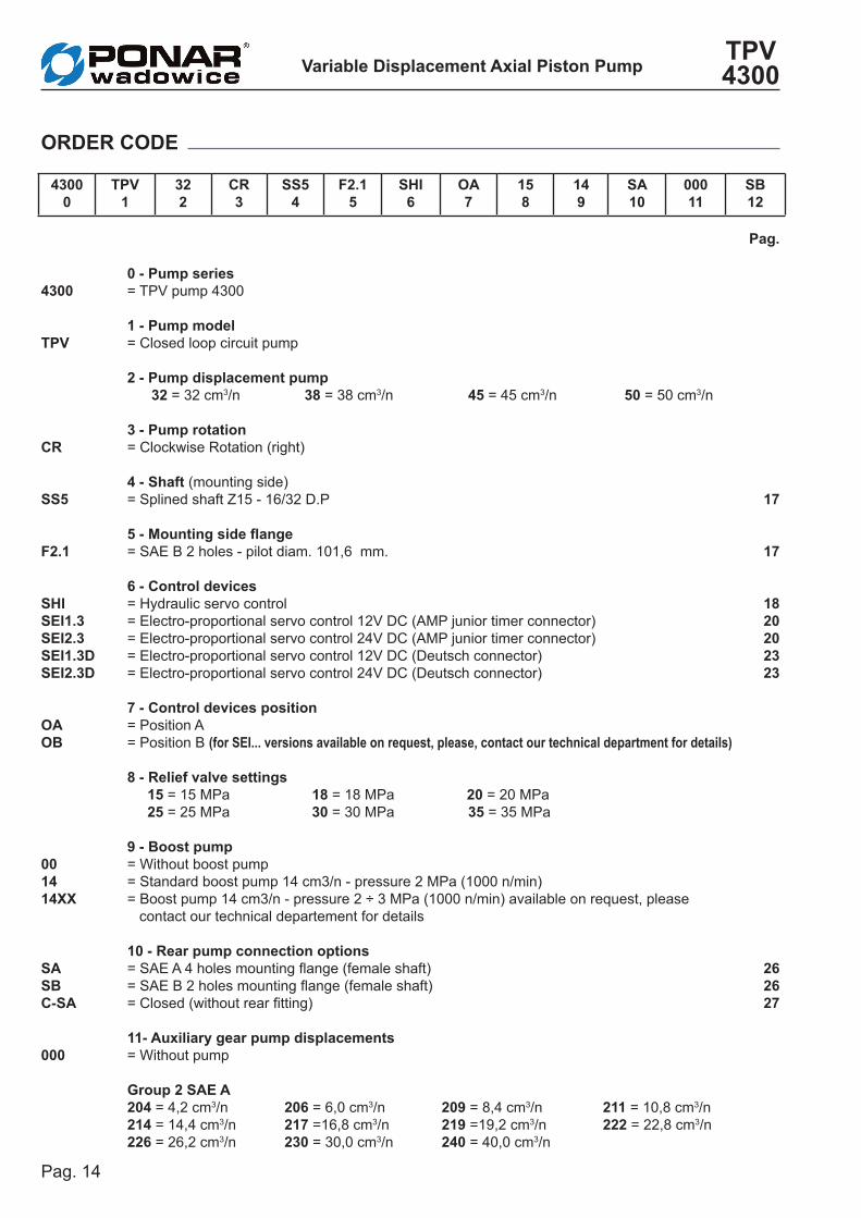
0 - Pump series= TPV pump 4300
1 - Pump model= Closed loop circuit pump
2 - Pump displacement pump 32 = 32 cm3/n 38 = 38 cm3/n 45 = 45 cm3/n 50 = 50 cm3/n
3 - Pump rotation= Clockwise Rotation (right)
4 - Shaft (mounting side)= Splined shaft Z15 - 16/32 D.P
5 - Mounting side flange= SAE B 2 holes - pilot diam. 101,6 mm.
6 - Control devices = Hydraulic servo control = Electro-proportional servo control 12V DC (AMP junior timer connector)= Electro-proportional servo control 24V DC (AMP junior timer connector)= Electro-proportional servo control 12V DC (Deutsch connector)= Electro-proportional servo control 24V DC (Deutsch connector)
7 - Control devices position= Position A= Position B (for SEI... versions available on request, please, contact our technical department for details)
8 - Relief valve settings 15 = 15 MPa 18 = 18 MPa 20 = 20 MPa 25 = 25 MPa 30 = 30 MPa 35 = 35 MPa
9 - boost pump = Without boost pump = Standard boost pump 14 cm3/n - pressure 2 MPa (1000 n/min) = Boost pump 14 cm3/n - pressure 2 ÷ 3 MPa (1000 n/min) available on request, please contact our technical departement for details 10 - Rear pump connection options = SAE A 4 holes mounting flange (female shaft) = SAE B 2 holes mounting flange (female shaft) = Closed (without rear fitting)
11- Auxiliary gear pump displacements= Without pump
Group 2 SAE A 204 = 4,2 cm3/n 206 = 6,0 cm3/n 209 = 8,4 cm3/n 211 = 10,8 cm3/n 214 = 14,4 cm3/n 217 =16,8 cm3/n 219 =19,2 cm3/n 222 = 22,8 cm3/n 226 = 26,2 cm3/n 230 = 30,0 cm3/n 240 = 40,0 cm3/n
4300
TPV
CR SS5
F2.1
SHI SEI1.3 SEI2.3 SEI1.3DSEI2.3D
OA Ob
001414XX
SA Sb C-SA
000
ORDER CODE
Pag.
17
17
1820202323
262627

Pag. 15
Variable Displacement Axial Piston PumpTPV 4300
Group 3 SAE b 315 = 15,0 cm3/n 318 = 18,0 cm3/n 321 = 21 cm3/n 327 = 27,0 cm3/n 332 = 32,0 cm3/n 338 = 38,0 cm3/n 343 = 43,0 cm3/n 347 = 47,0 cm3/n 351 = 51,0 cm3/n 354 = 54,0 cm3/n 361 = 61,0 cm3/n 364 = 64,0 cm3/n370 = 70,0 cm3/n 374 = 74,0 cm3/n 390 = 90,0 cm3/n
12 - Optional= Without optional= Screw by-pass (Standard)= Man on board solenoid valve 12V DC= Man on board solenoid valve 24V DC= Port threads and restrictor diameter
Example G/08 = 1/4" BSPP port threads and Ø 0,8 mm restrictor (SHI)Example -/08 = Ø 0,8 mm restrictor (SEI)
00SbmOb1mOb2G/J/m/-
(continued) ORDER CODE
282929
Servo control type Port threads Symbol Restrictor diameter (SHI/SEI)
STANDARDSEI Plugged - - Without restrictorSHI 1/4” BSPP G 06 Restrictor orifice ø 0,6 mm
ON REQUESTSHI JIC (7/16” - 20) J 08 Restrictor orifice ø 0,8 mmSHI METRIC (M12x1,5) M 10 Restrictor orifice ø 1,0 mm
12 Restrictor orifice ø 1,2 mm16 Restrictor orifice ø 1,6 mm20 Restrictor orifice ø 2,0 mm
Variable Displacement Axial Piston PumpTPV 4300
Pag. 16
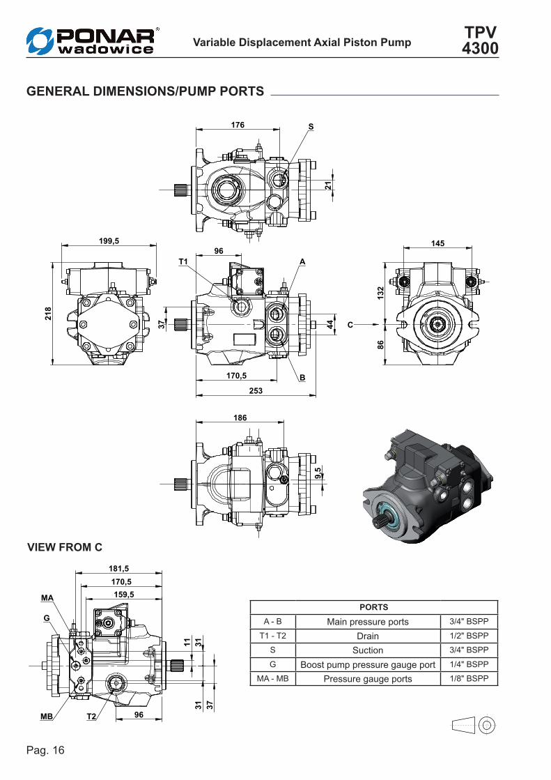
86
132
145
C
96
170,5
44
253
37
A
B
T1
218
199,5
176
21
S
186
9,5
PORTSA - B Main pressure ports 3/4" BSPP
T1 - T2 Drain 1/2" BSPP
S Suction 3/4" BSPP
G Boost pump pressure gauge port 1/4" BSPP
MA - MB Pressure gauge ports 1/8" BSPP
GENERAL DImENSIONS/PUmP PORTS
96
37
159,5 170,5
181,5
11
31
31
G
MA
MB T2
VIEW FROm C

Pag. 17
Variable Displacement Axial Piston PumpTPV 4300
SS5SPLINED SHAFT SAE-bb Z = 15Max. torque = 450 Nm
F2.1FLANGE SAE b - 2 bOLT
Attention: for the application of multiple pumps the total absorbed torque must not exceed the indicated value.
145
174
9,7 + 0,20
10
1,6
f7 - -0,
036
0,07
1
M6
12
16,5
38
46 + 0,30
Z15 16/32" D.P.
Ø14
N.2
SLO
TS
SHAFT OPTION AND mOUNTING FLANGE

Variable Displacement Axial Piston PumpTPV 4300
Pag. 18
90,
5
90,
5 70 70
132
143,1
56,2
56,2
77,2
77,2
P1
P2
The pump displacement variation is obtained by adjusting the pressure on P1 and P2 servo control ports by means of a hydraulic propor-tional joystick (with integrated pressure redu-cing valves).The servo control supply can be obtained by taking pressure from the boost pump (G port), see pag. 19. The servo control return time can be adjusted by inserting a restrictor on the joystick supply
line (0,5 ÷ 1,2 mm).The servo control operation curve, in both di-rections, goes from 0,4 to 1,8 MPa (tolerance (± 5 %).The adjusting curve of the hydraulic joystick has to be a little wider (0,3 ÷ 1,9 MPa).
SHI HYDRAULIC SERVO CONTROL

Pag. 19
Variable Displacement Axial Piston PumpTPV 4300
FLOW DIRECTION PUmPRotation Port OUT IN
Clockwise (CR) P1P2
BA
AB
Counter clockwise (CC) P1P2
AB
BA
S
G
T1
BA
T2
P1 P2
IN OUT
IN OUT
A
B
HYDRAULIC DIAGRAm
(continued)
SHI HYDRAULIC SERVO CONTROL

Variable Displacement Axial Piston PumpTPV 4300
Pag. 20
105
,5
91,1 91,1
218
34
128
132
53 EVP1
EVP2
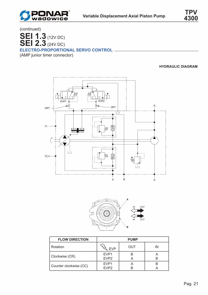
The pump displacement variation is obtained by an electric signal that goes from:● 0 to 750 mA (24V DC voltage)● 0 to 1500 mA (12V DC voltage)
SEI 1.3 (12V DC)
SEI 2.3 (24V DC)ELECTRO-PROPORTIONAL SERVO CONTROL(AMP junior timer connector)
Pag. 21
Variable Displacement Axial Piston PumpTPV 4300
FLOW DIRECTION PUmP
Rotation EVP OUT IN
Clockwise (CR) EVP1EVP2
BA
AB
Counter clockwise (CC) EVP1EVP2
AB
BA
S
G
T1
BA
T2
P T PT
EVP1 EVP2
OPT.OPT.
IN OUT
IN OUT
A
B
(continued)
SEI 1.3 (12V DC)
SEI 2.3 (24V DC)ELECTRO-PROPORTIONAL SERVO CONTROL(AMP junior timer connector)
HYDRAULIC DIAGRAm

Variable Displacement Axial Piston PumpTPV 4300
Pag. 22
SOLENOID VALVE HYDRAULIC FEATURESMax. pressure (P, T) pP= 5 MPa, pT= 3 MPa
Hysteresis (w/PWM)<0,07 MPa (pA=2,0)<0,1 MPa (pA=2,5)<0,15 MPa (pA=3,5)
Filtration ratio 125 µm
Oil contamination levelMin. filtration ratio: 20/18/15According ISO 4406Hydraulic oil DIN 51524
Min./max. oil temperature From -20 to +90°C
SOLENOID VALVE ELECTRICAL FEATURESVoltage 12 V DC 24 V DCElectric current 1500 mA 750 mALoad resistence 4,72 Ω ± 5% 20,8 Ω ± 5%
Type of controlCurrent control
PWM 100 Hz (suggested)Type of connection AMP Junior TimerProtection class Until IP6K6 / IPX9K
16
10%
50%
100%
200
400
600
800
1000
1200
1400
mA
% D
isplac
emen
t
10%
50%
100%
200
400
600
800
1000
1200
1400
% D
isplac
emen
t
mA
24V
24V
12V
12V
CURRENT-DISPLACEMENT GRAPHIC
1600
1600
(continued)
SEI 1.3 (12V DC)
SEI 2.3 (24V DC)ELECTRO-PROPORTIONAL SERVO CONTROL(AMP junior timer connector)

Pag. 23
Variable Displacement Axial Piston PumpTPV 4300
The pump displacement variation is obtained by an electric signal that goes from:● 0 to 750 mA (24V DC voltage)● 0 to 1500 mA (12V DC voltage)
SEI 1.3D (12V DC)
SEI 2.3D (24V DC)ELECTRO-PROPORTIONAL SERVO CONTROL(Deutsch connector)
105
,5
101,5 101,05
218
34
128
132
53 EVP1
EVP2

Variable Displacement Axial Piston PumpTPV 4300
Pag. 24
FLOW DIRECTION PUmP
Rotation EVP OUT IN
Clockwise (CR) EVP1EVP2
BA
AB
Counter clockwise (CC) EVP1EVP2
AB
BA
S
G
T1
BA
T2
P T PT
EVP1 EVP2
OPT.OPT.
IN OUT
IN OUT
A
B
(continued)
SEI 1.3D (12V DC)
SEI 2.3D (24V DC)ELECTRO-PROPORTIONAL SERVO CONTROL(Deutsch connector)
HYDRAULIC DIAGRAm

Pag. 25
Variable Displacement Axial Piston PumpTPV 4300
SOLENOID VALVE HYDRAULIC FEATURESMax. pressure (P, T) pP= 5 MPa, pT= 3 MPa
Hysteresis (w/PWM)<0,07 MPa (pA=2,0)<0,1 MPa (pA=2,5)<0,15 MPa (pA=3,5)
Filtration ratio 125 µm
Oil contamination levelMin. filtration ratio: 20/18/15According ISO 4406Hydraulic oil DIN 51524
Min./max. oil temperature From -20 to +90°C
SOLENOID VALVE ELECTRICAL FEATURESVoltage 12 V DC 24 V DCElectric current 1500 mA 750 mALoad resistence 4,72 Ω ± 5% 20,8 Ω ± 5%
Type of controlCurrent control
PWM 100 Hz (suggested)Type of connection DEUTSCH DT 04-2PProtection class Until IP6K6 / IPX9K
16 10%
50%
100%
200
400
600
800
1000
1200
1400
mA
% D
isplac
emen
t
10%
50%
100%
200
400
600
800
1000
1200
1400
% D
isplac
emen
t
mA
24V
24V
12V
12V
CURRENT-DISPLACEMENT GRAPHIC
1600
1600
(continued)
SEI 1.3D (12V DC)
SEI 2.3D (24V DC)ELECTRO-PROPORTIONAL SERVO CONTROL(Deutsch connector)
Variable Displacement Axial Piston PumpTPV 4300
Pag. 26
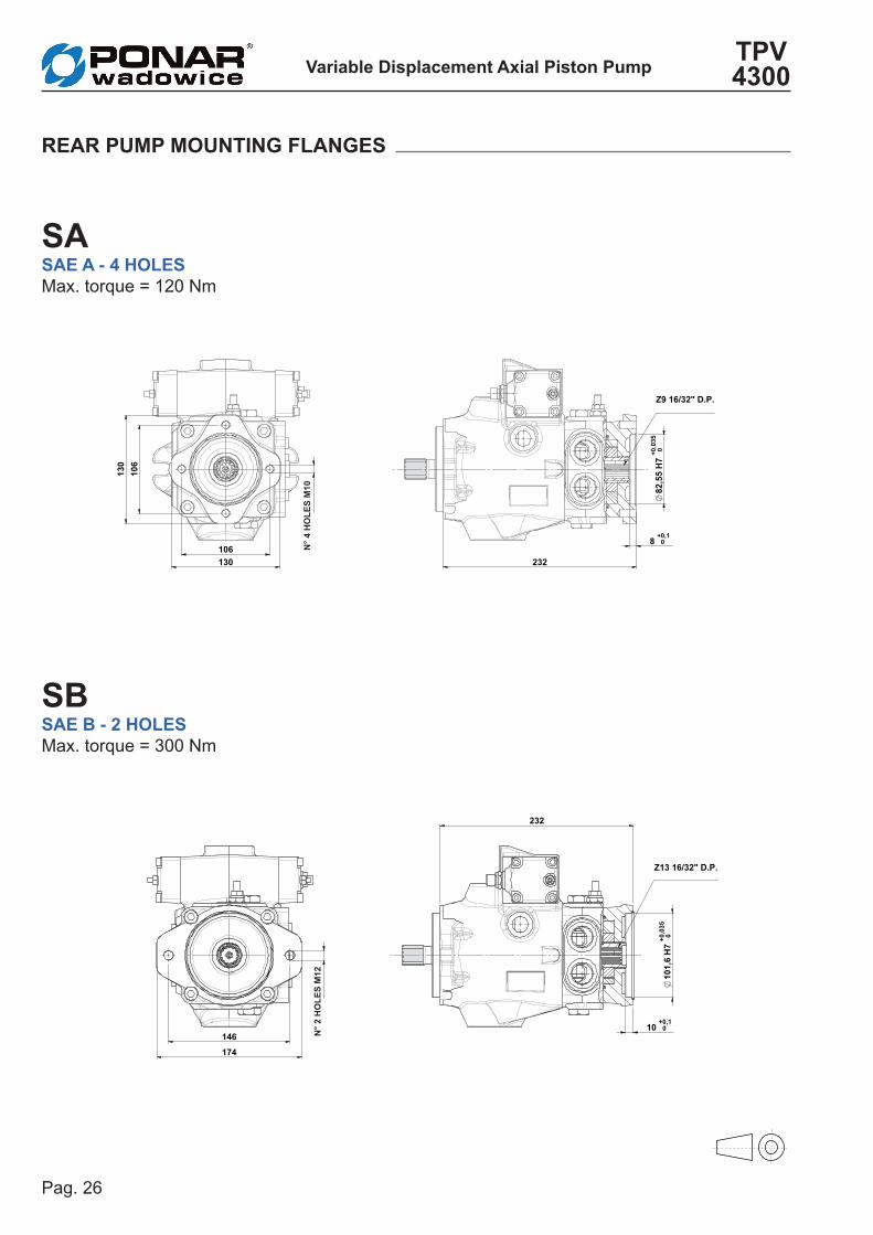
REAR PUmP mOUNTING FLANGES
SASAE A - 4 HOLESMax. torque = 120 Nm
SbSAE b - 2 HOLES Max. torque = 300 Nm
106
106
130
130
82
,55
H7
+ 0,03
50
8 + 0,10
232
Z9 16/32" D.P.
N° 4
HO
LES
m10
146
174
10
1,6
H7
+ 0,03
50
10 + 0,10
232
Z13 16/32" D.P.
N° 2
HO
LES
m12
Pag. 27
Variable Displacement Axial Piston PumpTPV 4300
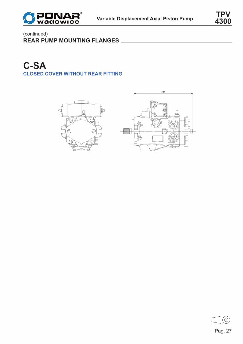
(continued) REAR PUmP mOUNTING FLANGES
253
C-SACLOSED COVER WITHOUT REAR FITTING

Variable Displacement Axial Piston PumpTPV 4300
Pag. 28
To by pass the oil flow from one direction to the other, with the pump not running or in emergency condition, a by pass screw can be actuated to connect the 2 lines of the hydrau-lic system. The orifice is completely open after 4 counter-clockwise rotations of the screw.
S
G
T1
BA
T2
P1 P2
OPTIONAL SbSCREW bY- PASS
HYDRAULIC DIAGRAm
170,5 30
83
5,5
73
A
A
KEY=
17

Pag. 29
Variable Displacement Axial Piston PumpTPV 4300
A normally open solenoid valve cuts the oil flow when not activated.The valve allows oil flow to feed the hydraulic system only if activated (the operator is sea-ted). The solenoid valve is available for 12V or 24V DC voltage.
S
G
T1
BA
T2
P1 P2
2
1
OPT. OPT.
125,5
41
30 1
1
118
,8
92,5
39
81,2
96,5
28
135,5
144,5
194,5
OPTIONAL mObmAN ON bOARD
HYDRAULIC DIAGRAm

Variable Displacement Axial Piston PumpTPV 4300
Pag. 30
TECHNICAL FEATURES
(continued)
OPTIONAL mObmAN ON bOARD
mOb VALVE - Hydraulic characteristicsMax. operating pressure 30 MPa
Max. flow 40 lt/min.
Internal leakage max. 5 drops/min. at 30 MPa
Response time energized 20 msDe-energized 30 msTemperature range from -20°C to 90°C
2
1
mOb VALVE - Electrical characteristicsPower 18 W
Various voltage options available (AC/DC)
Wire insulation Class HDuty factor ED 100%Supply power tolerance + 10%, - 15% (DC)Ambient temperature from -30°C to 60°CSeveral connector options available

TPVT 4300VARIAbLE DISPLACEmENT AXIAL PISTON TANDEm PUmP
Variable Displacement Axial Piston - Tandem PumpTPVT 4300
Pag. 32
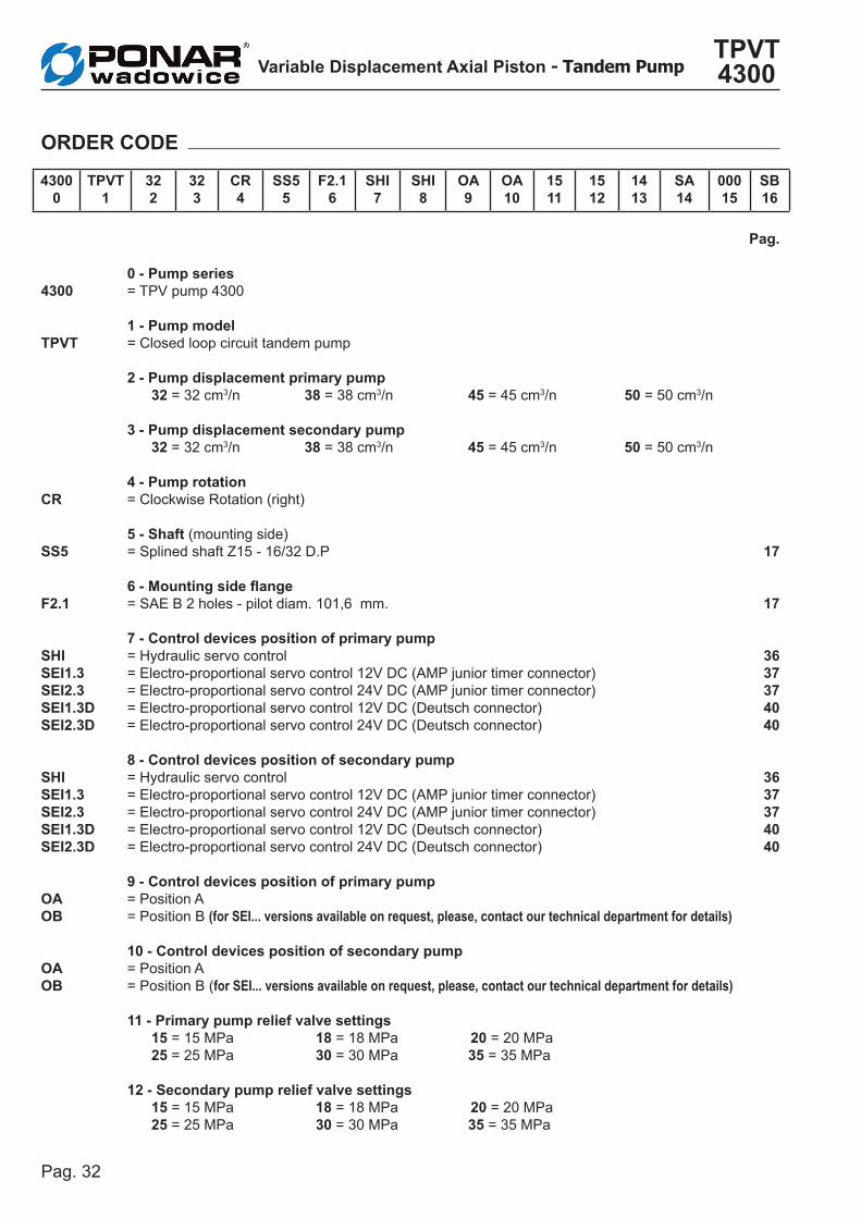
0 - Pump series= TPV pump 4300
1 - Pump model= Closed loop circuit tandem pump
2 - Pump displacement primary pump 32 = 32 cm3/n 38 = 38 cm3/n 45 = 45 cm3/n 50 = 50 cm3/n
3 - Pump displacement secondary pump 32 = 32 cm3/n 38 = 38 cm3/n 45 = 45 cm3/n 50 = 50 cm3/n
4 - Pump rotation= Clockwise Rotation (right)
5 - Shaft (mounting side)= Splined shaft Z15 - 16/32 D.P
6 - Mounting side flange= SAE B 2 holes - pilot diam. 101,6 mm.
7 - Control devices position of primary pump = Hydraulic servo control = Electro-proportional servo control 12V DC (AMP junior timer connector)= Electro-proportional servo control 24V DC (AMP junior timer connector)= Electro-proportional servo control 12V DC (Deutsch connector)= Electro-proportional servo control 24V DC (Deutsch connector)
8 - Control devices position of secondary pump = Hydraulic servo control = Electro-proportional servo control 12V DC (AMP junior timer connector)= Electro-proportional servo control 24V DC (AMP junior timer connector)= Electro-proportional servo control 12V DC (Deutsch connector)= Electro-proportional servo control 24V DC (Deutsch connector) 9 - Control devices position of primary pump= Position A= Position B (for SEI... versions available on request, please, contact our technical department for details)
10 - Control devices position of secondary pump= Position A= Position B (for SEI... versions available on request, please, contact our technical department for details)
11 - Primary pump relief valve settings 15 = 15 MPa 18 = 18 MPa 20 = 20 MPa 25 = 25 MPa 30 = 30 MPa 35 = 35 MPa 12 - Secondary pump relief valve settings 15 = 15 MPa 18 = 18 MPa 20 = 20 MPa 25 = 25 MPa 30 = 30 MPa 35 = 35 MPa
43000
TPVT1
322
323
CR4
SS55
F2.16
SHI7
SHI8
OA9
OA10
1511
1512
1413
SA14
00015
Sb16
4300
TPVT
CR SS5
F2.1
SHI SEI1.3 SEI2.3 SEI1.3DSEI2.3D
SHI SEI1.3 SEI2.3 SEI1.3DSEI2.3D
OA Ob
OA Ob
ORDER CODE
Pag.
17
17
3637374040
3637374040
Pag. 33
Variable Displacement Axial Piston - Tandem PumpTPVT 4300
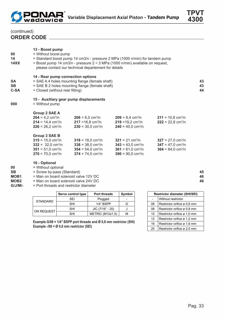
13 - boost pump = Without boost pump = Standard boost pump 14 cm3/n - pressure 2 MPa (1000 n/min) for tandem pump= Boost pump 14 cm3/n - pressure 2 ÷ 3 MPa (1000 n/min) available on request, please contact our technical departement for details 14 - Rear pump connection options = SAE A 4 holes mounting flange (female shaft) = SAE B 2 holes mounting flange (female shaft)= Closed (without rear fitting)
15 - Auxiliary gear pump displacements= Without pump
Group 2 SAE A 204 = 4,2 cm3/n 206 = 6,0 cm3/n 209 = 8,4 cm3/n 211 = 10,8 cm3/n 214 = 14,4 cm3/n 217 =16,8 cm3/n 219 =19,2 cm3/n 222 = 22,8 cm3/n 226 = 26,2 cm3/n 230 = 30,0 cm3/n 240 = 40,0 cm3/n
Group 3 SAE b 315 = 15,0 cm3/n 318 = 18,0 cm3/n 321 = 21 cm3/n 327 = 27,0 cm3/n 332 = 32,0 cm3/n 338 = 38,0 cm3/n 343 = 43,0 cm3/n 347 = 47,0 cm3/n 351 = 51,0 cm3/n 354 = 54,0 cm3/n 361 = 61,0 cm3/n 364 = 64,0 cm3/n370 = 70,0 cm3/n 374 = 74,0 cm3/n 390 = 90,0 cm3/n
16 - Optional= Without optional= Screw by-pass (Standard)= Man on board solenoid valve 12V DC= Man on board solenoid valve 24V DC= Port threads and restrictor diameter
Example G/08 = 1/4" BSPP port threads and Ø 0,8 mm restrictor (SHI)Example -/08 = Ø 0,8 mm restrictor (SEI)
001414XX
SA SbC-SA
000
00SbmOb1mOb2G/J/m/-
(continued) ORDER CODE
434344
454646
Servo control type Port threads Symbol Restrictor diameter (SHI/SEI)
STANDARDSEI Plugged - - Without restrictorSHI 1/4” BSPP G 06 Restrictor orifice ø 0,6 mm
ON REQUESTSHI JIC (7/16” - 20) J 08 Restrictor orifice ø 0,8 mmSHI METRIC (M12x1,5) M 10 Restrictor orifice ø 1,0 mm
12 Restrictor orifice ø 1,2 mm16 Restrictor orifice ø 1,6 mm20 Restrictor orifice ø 2,0 mm

Variable Displacement Axial Piston - Tandem PumpTPVT 4300
Pag. 34
PORTSA1 - B1 Main pressure ports 1 3/4" BSPPA2 - B2 Main pressure ports 2 3/4" BSPPT1 - T2 Drain 1/2" BSPP
S Suction 3/4" BSPP
G1 - G2 Boost pumps pressure gauge ports 1/8" BSPP
MA1- MB1/MA2 - MB2 Pressure gauge ports 1/8" BSPP
GENERAL DImENSIONS/TANDEm PUmP PORTS
132
8
6
145
C 37
316 96
170,5
390,5 473
44
A1
B1
A2
B2
T1
218
202
406
9,5
396
21
S
159,5 170,5
181,5
379,5
390,5 401,5
11 3
1 3
1
11
31
31
T2
MA1
MB1
MA2
MB2
G2G1
VIEW FROm C

Pag. 35
Variable Displacement Axial Piston - Tandem PumpTPVT 4300
PORTSA1 - B1 Main pressure ports 1 3/4" BSPPA2 - B2 Main pressure ports 2 3/4" BSPPT1 - T2 Drain 1/2" BSPP
S Suction 3/4" BSPP
G1 - G2 Boost pumps pressure gauge ports 1/8" BSPP
MA1- MB1/MA2 - MB2 Pressure gauge ports 1/8" BSPP
70 70
90,
5
90,
5
143,1
363,1
132
56,2
77,2
56,2
77,2
276,2
297,2
276,2
297,2
P1
P2
P4
P3
The pump displacement variation is obtained by adjusting the pressure on P1, P2, P3 and P4 servo control ports by means of a hydrau-lic proportional joystick (with integrated pres-sure reducing valves).The servo control oil supply can be obtained by taking pressure from the boost pump (G1 - G2 ports), see pag. 34. The servo control return time can be adjusted
by inserting a restrictor on the joystick supply line (0,5 ÷ 1,2 mm).The servo control operation curve, in both di-rections, goes from 0,4 to 1,8 MPa (tolerance (± 5 %).The adjusting curve of the hydraulic joystick has to be a little wider (0,3 ÷ 1,9 MPa).
SHI HYDRAULIC SERVO CONTROL

Variable Displacement Axial Piston - Tandem PumpTPVT 4300
Pag. 36
FLOW DIRECTION PRImARY PUmP SECONDARY PUmPRotation Port OUT IN Port OUT IN
Clockwise (CR) P1P2
B1A1
A1B1
P3P4
B2A2
A2B2
Counter clockwise (CC) P1P2
A1B1
B1A1
P3P4
A2B2
B2A2
HYDRAULIC DIAGRAm
(continued)
SHI HYDRAULIC SERVO CONTROL
IN OUT
IN OUT
A
B
1 - A2
1 - b2
T1 B1A1
T2
S
G
B2A2
GP1 P2 P1 P2
T2
T1
1
G2

Pag. 37
Variable Displacement Axial Piston - Tandem PumpTPVT 4300
33,5
128
132
253,5
53
273
EVP1
EVP2
EVP4
EVP3
91,1 91,1
105
,5
218
The pump displacement variation is obtained by an electric signal that goes from:● 0 to 750 mA (24V DC voltage)● 0 to 1500 mA (12V DC voltage)
SEI 1.3 (12V DC)
SEI 2.3 (24V DC)ELECTRO-PROPORTIONAL SERVO CONTROL(AMP junior timer connector)

Variable Displacement Axial Piston - Tandem PumpTPVT 4300
Pag. 38
FLOW DIRECTION PRImARY PUmP SECONDARY PUmP
Rotation EVP
OUT INEVP
OUT IN
Clockwise (CR) EVP1EVP2
B1A1
A1B1
EVP3EVP4
B2A2
A2B2
Counter clockwise (CC) EVP1EVP2
A1B1
B1A1
EVP3EVP4
A2B2
B2A2
T1 B1A1 S
G
B2A2
T2
T1
P T PT
EVP3 EVP4
OPT.
P T PT
EVP1 EVP2
OPT.OPT.
G
T2
(continued)
SEI 1.3 (12V DC)
SEI 2.3 (24V DC)ELECTRO-PROPORTIONAL SERVO CONTROL(AMP junior timer connector)
HYDRAULIC DIAGRAm
IN OUT
IN OUT
A
B
1 - A2
1 - b2

Pag. 39
Variable Displacement Axial Piston - Tandem PumpTPVT 4300
(continued)
SEI 1.3 (12V DC)
SEI 2.3 (24V DC)ELECTRO-PROPORTIONAL SERVO CONTROL(AMP junior timer connector)
SOLENOID VALVE HYDRAULIC FEATURESMax. pressure (P, T) pP= 5 MPa, pT= 3 MPa
Hysteresis (w/PWM)<0,07 MPa (pA=2,0)<0,1 MPa (pA=2,5)<0,15 MPa (pA=3,5)
Filtration ratio 125 µm
Oil contamination levelMin. filtration ratio: 20/18/15According ISO 4406Hydraulic oil DIN 51524
Min./max. oil temperature From -20 to +90°C
SOLENOID VALVE ELECTRICAL FEATURESVoltage 12 V DC 24 V DCElectric current 1500 mA 750 mALoad resistence 4,72 Ω ± 5% 20,8 Ω ± 5%
Type of controlCurrent control
PWM 100 Hz (suggested)Type of connection AMP Junior TimerProtection class Until IP6K6 / IPX9K
16
10%
50%
100%
200
400
600
800
1000
1200
1400
mA
% D
isplac
emen
t
10%
50%
100%
200
400
600
800
1000
1200
1400
% D
isplac
emen
t
mA
24V
24V
12V
12V
CURRENT-DISPLACEMENT GRAPHIC
1600
1600

Variable Displacement Axial Piston - Tandem PumpTPVT 4300
Pag. 40
The pump displacement variation is obtained by an electric signal that goes from:● 0 to 750 mA (24V DC voltage)● 0 to 1500 mA (12V DC voltage)
SEI 1.3D (12V DC)
SEI 2.3D (24V DC)ELECTRO-PROPORTIONAL SERVO CONTROL(Deutsch connector)
33,5
128
132
253,5
53
273
EVP1
EVP2
EVP4
EVP3
101,5 101,05
105
,5
218

Pag. 41
Variable Displacement Axial Piston - Tandem PumpTPVT 4300
FLOW DIRECTION PRImARY PUmP SECONDARY PUmP
Rotation EVP
OUT INEVP
OUT IN
Clockwise (CR) EVP1EVP2
B1A1
A1B1
EVP3EVP4
B2A2
A2B2
Counter clockwise (CC) EVP1EVP2
A1B1
B1A1
EVP3EVP4
A2B2
B2A2
T1 B1A1 S
G
B2A2
T2
T1
P T PT
EVP3 EVP4
OPT.
P T PT
EVP1 EVP2
OPT.OPT.
G
T2
(continued)
SEI 1.3D (12V DC)
SEI 2.3D (24V DC)ELECTRO-PROPORTIONAL SERVO CONTROL(Deutsch connector)
HYDRAULIC DIAGRAm
IN OUT
IN OUT
A
B
1 - A2
1 - b2

Variable Displacement Axial Piston - Tandem PumpTPVT 4300
Pag. 42
(continued)
SEI 1.3D (12V DC)
SEI 2.3D (24V DC)ELECTRO-PROPORTIONAL SERVO CONTROL(Deutsch connector)
SOLENOID VALVE HYDRAULIC FEATURESMax. pressure (P, T) pP= 5 MPa, pT= 3 MPa
Hysteresis (w/PWM)<0,07 MPa (pA=2,0)<0,1 MPa (pA=2,5)<0,15 MPa (pA=3,5)
Filtration ratio 125 µm
Oil contamination levelMin. filtration ratio: 20/18/15According ISO 4406Hydraulic oil DIN 51524
Min./max. oil temperature From -20 to +90°C
SOLENOID VALVE ELECTRICAL FEATURESVoltage 12 V DC 24 V DCElectric current 1500 mA 750 mALoad resistence 4,72 Ω ± 5% 20,8 Ω ± 5%
Type of controlCurrent control
PWM 100 Hz (suggested)Type of connection DEUTSCH DT 04-2PProtection class Until IP6K6 / IPX9K
16
10%
50%
100%
200
400
600
800
1000
1200
1400
mA
% D
isplac
emen
t
10%
50%
100%
200
400
600
800
1000
1200
1400
% D
isplac
emen
t
mA
24V
24V
12V
12V
CURRENT-DISPLACEMENT GRAPHIC
1600
1600

Pag. 43
Variable Displacement Axial Piston - Tandem PumpTPVT 4300
130
106
106
1
30
82
,55
H7
+ 0,03
50
8 + 0,10
452
Z9 16/32" D.P.
146
174
10
1,6
H7
+ 0,03
50
10 + 0,10
452
Z13 16/32" D.P.
REAR PUmP mOUNTING FLANGES
SASAE A - 4 HOLESMax. torque = 120 Nm
SbSAE b - 2 HOLES Max. torque = 300 Nm
N° 4
HO
LES
m10
N° 2
HO
LES
m12

Variable Displacement Axial Piston - Tandem PumpTPVT 4300
Pag. 44
473
(continued) REAR PUmP mOUNTING FLANGES
C-SACLOSED COVER WITHOUT REAR FITTING
Pag. 45
Variable Displacement Axial Piston - Tandem PumpTPVT 4300
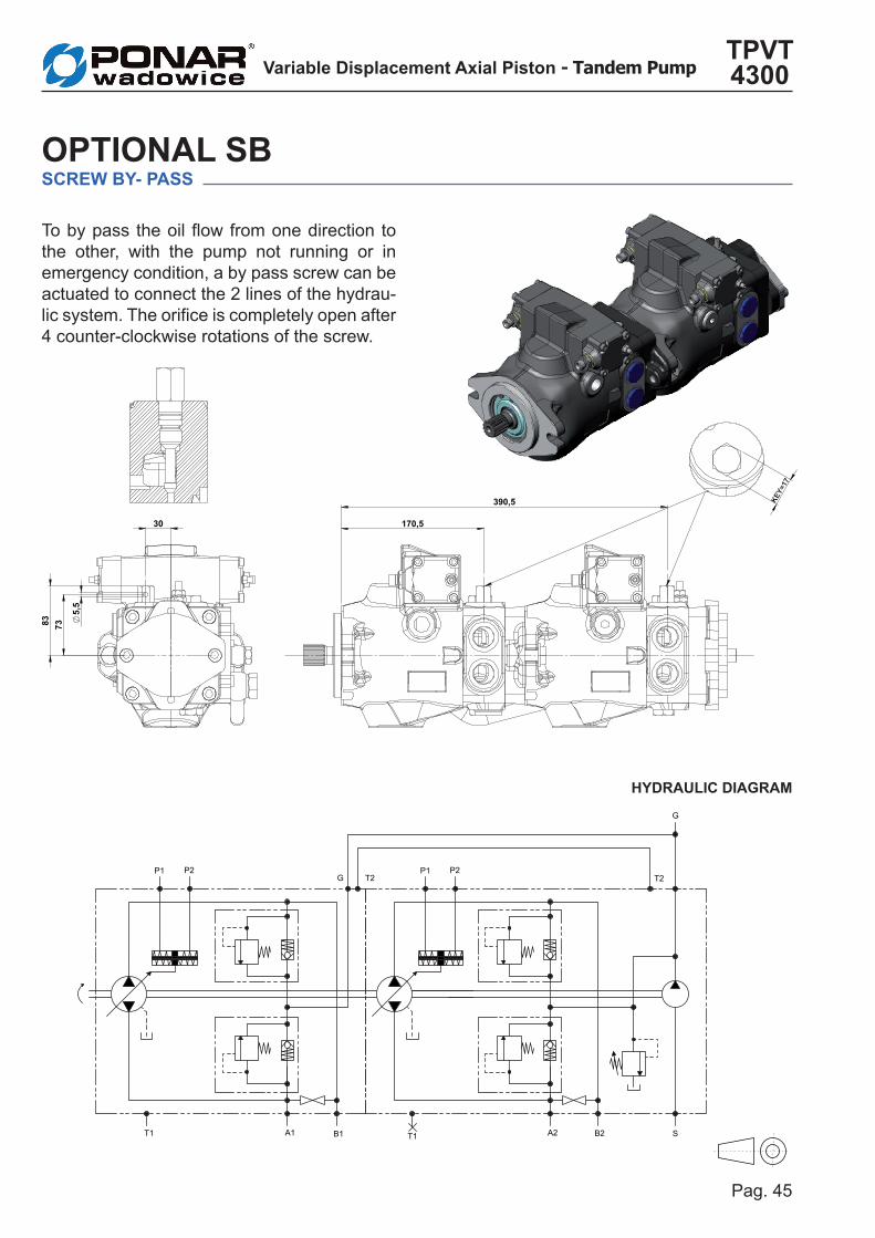
To by pass the oil flow from one direction to the other, with the pump not running or in emergency condition, a by pass screw can be actuated to connect the 2 lines of the hydrau-lic system. The orifice is completely open after 4 counter-clockwise rotations of the screw.
ERRORE:T
IMBRO
Dimensioni espresse in mm Unless otherwiswe specified all dimensions are in mm
ERRORE:REV_02ERRORE:REV_01
ERRORE:DESCR_REV_02ERRORE:DESCR_REV_01 ERRORE:DATA_REV_01_TXTERRORE:FIRMA_REV_01
00
4200 TPVT 50 50 CR SS5 F2.1 SHI OA OA 35 14 C 000 SB
ERRORE:REVISIONE 14/09/2015MD
SOSTITUISCE CODICESOSTITUITO DA CODICE
DATA - DATE
AccessoriesGear-Boxes
Hydrostatic TransmissionsHydraulic Components ERRORE:Assieme
ERRORE:Prof. tratt. sup.CODICE - CODE VER.
FOGLIO - SHEET
SCALA - SCALE
DATA - DATEAPPROV. - CHECKED DISEGNATO - DRAWN
DESCRIZIONE - DESCRIPTION
FILE MASSA - WEIGHT44.97 ERRORE:CodiceTPV 4200 OTIONAL SB TANDEM ERRORE:SOSTITUISCE_CODICEERRORE:SOSTITUITO_DA_CODICE
2/ 2
1:2REPLACED BY CODE REPLACE CODEREV.
HANSA TMP srl siriserva a termini di legge la proprietà di questo disegno, con divieto di riprodurlo o di renderlo comunque noto a terzi senza specifica approvazione.HANSA TMP srl holds the legal propriety rights of this drawing.Unautharised reproduction or disclosure of the drawing to third parties is forbidden
REVIS
IONI
- REV
ISION
S
ERRORE:DESCR_REV_03ERRORE:DESCR_REV_04ERRORE:DESCR_REV_05
ERRORE:REV_03ERRORE:REV_04ERRORE:REV_05
ERRORE:DATA_REV_02_TXTERRORE:FIRMA_REV_02ERRORE:DATA_REV_03_TXTERRORE:FIRMA_REV_03ERRORE:DATA_REV_04_TXTERRORE:FIRMA_REV_04ERRORE:DATA_REV_05_TXTERRORE:FIRMA_REV_05
HANSA - TMPsrl
TH
T1 B1A1
T2
S
G
B2A2
GP1 P2 P1 P2
T2
T1
OPTIONAL SbSCREW bY- PASS
HYDRAULIC DIAGRAm
30
83
5,5
73
170,5
390,5
A
AKEY=
17

Variable Displacement Axial Piston - Tandem PumpTPVT 4300
Pag. 46
ERRORE:T
IMBRO
Dimensioni espresse in mm Unless otherwiswe specified all dimensions are in mm
ERRORE:REV_02ERRORE:REV_01
ERRORE:DESCR_REV_02ERRORE:DESCR_REV_01 ERRORE:DATA_REV_01_TXTERRORE:FIRMA_REV_01
00
4200 TPVT 50 50 CR SS5 F2.1 SHI OA OA 35 14 C 000 MOB1
ERRORE:REVISIONE 14/09/2015MD
SOSTITUISCE CODICESOSTITUITO DA CODICE
DATA - DATE
AccessoriesGear-Boxes
Hydrostatic TransmissionsHydraulic Components ERRORE:Assieme
ERRORE:Prof. tratt. sup.CODICE - CODE VER.
FOGLIO - SHEET
SCALA - SCALE
DATA - DATEAPPROV. - CHECKED DISEGNATO - DRAWN
DESCRIZIONE - DESCRIPTION
FILE MASSA - WEIGHT45.28 ERRORE:CodiceTPV 4200 OPTIONAL MOB TANDEM ERRORE:SOSTITUISCE_CODICEERRORE:SOSTITUITO_DA_CODICE
2/ 2
1:2REPLACED BY CODE REPLACE CODEREV.
HANSA TMP srl siriserva a termini di legge la proprietà di questo disegno, con divieto di riprodurlo o di renderlo comunque noto a terzi senza specifica approvazione.HANSA TMP srl holds the legal propriety rights of this drawing.Unautharised reproduction or disclosure of the drawing to third parties is forbidden
REVIS
IONI
- REV
ISION
S
ERRORE:DESCR_REV_03ERRORE:DESCR_REV_04ERRORE:DESCR_REV_05
ERRORE:REV_03ERRORE:REV_04ERRORE:REV_05
ERRORE:DATA_REV_02_TXTERRORE:FIRMA_REV_02ERRORE:DATA_REV_03_TXTERRORE:FIRMA_REV_03ERRORE:DATA_REV_04_TXTERRORE:FIRMA_REV_04ERRORE:DATA_REV_05_TXTERRORE:FIRMA_REV_05
HANSA - TMPsrl
TH
11
30
118
,8
92,5 42
125,5
39
301,2
316,5 355,5
364,5 414,5
T1 B1A1
T2
S
G
B2A2
GP1 P2 P3 P4
T2
T1
2
1
OPT. OPT. OPT. OPT.
A normally open solenoid valve cuts the oil flow when not activated.The valve allows oil flow to feed the hydraulic system only if activated (the operator is sea-ted). The solenoid valve is available for 12V or 24V DC voltage.
OPTIONAL mObmAN ON bOARD
HYDRAULIC DIAGRAm

Pag. 47
Variable Displacement Axial Piston - Tandem PumpTPVT 4300
TECHNICAL FEATURES
(continued)
OPTIONAL mObmAN ON bOARD
mOb VALVE - Hydraulic characteristicsMax. operating pressure 30 MPa
Max. flow 40 lt/min.
Internal leakage max. 5 drops/min. at 30 MPa
Response time energized 20 msDe-energized 30 msTemperature range from -20°C to 90°C
2
1
mOb VALVE - Electrical characteristicsPower 18 W
Various voltage options available (AC/DC)
Wire insulation Class HDuty factor ED 100%Supply power tolerance + 10%, - 15% (DC)Ambient temperature from -30°C to 60°CSeveral connector options available

Variable Displacement Axial Piston PumpTPV 4300
Pag. 48
TROUbLE SHOOTING
TROUbLES CAUSE REmEDY
High noise level
Too high rotation speed of the pump. Reduce pump rotation speed.Wrong rotation direction. Check the rotation direction of the pump.
Obstruction in suction line - air in the suction line - wrong oil viscosity - diameter of suction line too small.
Check oil type and viscosity. Check internal diameter of suction line. Remove restrictions. Check oil level of reservoir. Eliminate air intake.
Not correct connection of the pump.Not correct diameter of pipes / hoses.
Check the pump connections and the pipe / hose diameters according to notes.
Vibrations of relief valves . Check the inlet suction line - Check and replace relief valves.
Internal parts worn out. Check and replace.Wrong pump connection to the prime mover.
Check connection and rotation of direction.
Too low rotation speed of the pump. Increase the pump rotation speed.
Low flow rate
Obstructions in the suction line - wrong viscosity.
Check oil type and viscosity. Check internal diameter of suction line. Remove restrictions. Check oil level of reservoir. Eliminate air intake.
Low remote control pressure. Check and adjust.High internal leakage. Check the case drain flow.Low rotation speed of the pump. Increase speed of the pump.
Instable or low pressure
Obstruction of suction line - air in the suction line - wrong oil viscosity - diameter of suction line too small.
Check oil type and viscosity. Check internal diameter of suction line. Remove restrictions. Check oil level of reservoir. Eliminate air intake.
Vibration of relief valves. Check the inlet suction line. Check and replace relief valves.
Internal parts worn out. Check and replace.
Over heating High oil temperature at suction inlet. Check the cooling system.Internal parts worn out. Check - replace.Wrong setting of relief valves. Check - adjust the setting of relief valves.

Pag. 49
Variable Displacement Axial Piston PumpTPV 4300
VARIABLE DISPLACEMENT AXIAL PISTON PUMPS TPV 618
CAmPANE E GIUNTI
AC/DC ELECTRIC MOTORS
HYDRAULIC PILOT CONTROLS
OPTIONAL ON REQUEST
HT 16 / M / 107 / 0804 / E -24
VARIABLE DISPLACEMENT AXIAL PISTON PUMPS TPV 618
FLANGES AND COUPLINGSmO
mOTORI A SCOPPIO
HT 16 / M / 107 / 0804 / E -24
������������������������������������������������������������������ ���� �����������������������������������������
���������������������������������������������������������������������������������������������������������������������������
������������������
����������������
Hydraulic Remote Servo Controls
Flanges and Couplings for Gasoline and Diesel engines
Electric Remote Servo Controls
Hydraulic Gear Pump SAE AHydraulic Gear Pump SAE b
ACCESSORIES
For more detailed information ask for catalogue HT 15 F 20..........
For more detailed information ask for catalogue HT 73 B 20..........
For more detailed information ask our technical departement
GASOLINE OR DIESEL ENGINES
FLANGES AND COUPLINGS
For more detailed information ask for catalogue HT 73 B 10..........


As PONAR Wadowice has a very extensive range of products and some products have a variety of applications, the information supplied may often only apply to specific situations.
If the catalogue does not supply all the information required, please contact PONAR Wadowice.In order to provide a comprehensive reply to queries we may require specific data regarding the proposed application.
Whilst every reasonable endeavour has been made to ensure accuracy, this publication cannot be considered to represent part of any contract, whether expressed or implied.
The data is this catalogue refer to the standard product. The policy of PONAR Wadowice consists of a continuous improvement of its products. It reserves the right to change the specifications of the different products whenever necessary and without giving prior information.
PONAR Wadowice S.A.ul. Wojska Polskiego 29 34-100 WadowiceTel.: +48 33 488 21 00Fax: +48 33 488 21 03E-mail: [email protected]: www.ponar-wadowice.pl