tr 95{52 - sophia - inria publis/synccharts... · a reason for this lac k, ... able 1 expresses dep...
TRANSCRIPT

SyncCharts: A Visual Representation of Reactive Behaviors
Charles ANDRE
October 1995, revision April 27, 1996
Abstract
This report is an introduction to SyncCharts (Synchronous Charts) a new graphical representationof reactive behaviors based on the synchronous paradigm. Syntactically this model is close to State-charts and Argos. It o�ers enhanced preemption capabilities. Its semantics is formally de�ned and anySynchronous Charts can be translated into an equivalent Esterel program.
SyncCharts combines state-oriented descriptions, hierarchy and powerful preemption mechanisms. Itis fully compatible with the imperative synchronous language Esterel and it encourages programmingwith both textual and graphical reprensentations.
1 Introduction
A reactive system maintains permanent interactions with its environment. Usually, reactive systems areconcurrent systems. Their global behavior results from the cooperation of their components (subsystems). Inorder to carry out an expected behavior, the evolutions of subsystems must be coordinated. Communication(information exchange) plays a central role in this coordination, and consequently, reactive systems areoften viewed as communicating processes. This approach relegates preemption to a position of secondaryimportance, which is prejudicial to many reactive applications. \A process preemption . . . consists in denyingthe right to work to a process, either permanently (abortion) or temporarily (suspension)" (G. Berry [Ber92]).Real-time operating systems, interrupt-driven systems, and more generally, control-oriented systems heavilyrely on preemption. The speci�cation of such systems needs preemption as a �rst class concept; theirprogramming requires preemption primitives. Few models can deal with preemption. Languages that supportpreemption, to some extent, do not o�er primitives tailored to reactive applications. A reason for this lack,is that most semantics dealing with both concurrency and preemption are complex or vague.
Faced with this problem, we adopt a synchronous approach [BB91]. The \perfect synchrony hypothesis"assumes on the one hand that cause (stimuli) and e�ect (reaction) are simultaneous, and on the other handthat information is instantaneously broadcast. These assumptions lead to an abstract view of temporal be-haviors, in which sequencing, concurrency and preemption can be considered as orthogonal concepts. Withinthe framework of synchronous programming, clear mathematical semantics can be given to several forms ofpreemption. This point of view is advocated in a G. Berry's paper entitled \Preemption in ConcurrentSystems" [Ber92]. In what follows, we shall often refer to this paper which brings the theoretical foundationof our contribution.
Engineers in the �eld of control and manufacturing systems are somewhat reluctant to synchronouslanguages. As a rule, they prefer graphical approaches. The Grafcet [IEC88] (Sequential Function Charts)is widely used for industrial logic control. StateCharts [Har87], a hierarchical visual model which is partof the Statemate environment, allows design of complex reactive system and it takes advantages fromits industrial support. StateCharts is convenient but, as stated in a review of the various extensionsof StateCharts [Bee94], its semantics has to be clari�ed. Argos [Mar90] is another synchronous andgraphical model. It is based on a clear semantics, but it has not been widely distributed. In this report,we introduce SyncCharts (an acronym for Synchronous Charts) which inherits from StateCharts andArgos. Compared to its predecessors, SyncCharts deals with preemptions in a more rational way. Ituses a restricted set of powerful graphical primitives.Its semantics is founded on a process calculus and a\synchronous charts" can be automatically translated into an Esterel program.
1
TR 95{52 2
Graphical description has its own limits. We advocate using a multiformalism approach. SyncChartsallows graphical and textual re�nements. Both are possible thanks to the underlying formal semantics:Macrostate graphs and Esterel's modules can be abstracted into a common model.
Plan
The paper is organized as follows:
� In a �rst part, we identify the basic needs for describing reactive behaviors. With the help of simpleexamples, we explain how SyncCharts can ful�ll these demands.
� We then introduce a process calculus. This is a convenient way to express complex behaviors and toformally compare them.
� The third part is devoted to the syntax of SyncCharts.
� The expected behavior of a SyncCharts is formally expressed in the fourth section.
� Translations from SyncCharts into Esterel are given in the annex.
2 Main features of SyncCharts
This section is an informal introduction to SyncCharts. With the help of a progressively enriched example,we identify needs for a graphical representation of reactive behaviors. For each requirement, we introducethe solution adopted by SyncCharts.
A well-known basic model for discrete systems is the sequential machine (including Moore and Mealymachines). For industrial applications Grafcet (Sequential Function Charts) is widely used. More recentcontributions are StateCharts and Argos. All these models are based on the notion of state, so isSyncCharts which inherits from them.
2.1 An example: a SR ip- op
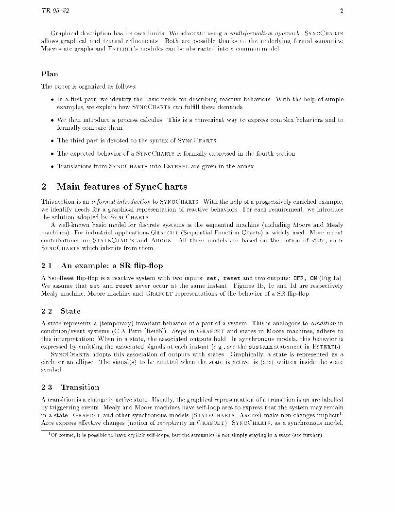
A Set-Reset ip- op is a reactive system with two inputs: set, reset and two outputs: OFF, ON (Fig.1a).We assume that set and reset never occur at the same instant. Figures 1b, 1c and 1d are respectivelyMealy machine, Moore machine and Grafcet representations of the behavior of a SR ip- op.
2.2 State
A state represents a (temporary) invariant behavior of a part of a system. This is analogous to condition incondition/event systems (C.A Petri [Rei85]). Steps in Grafcet and states in Moore machines, adhere tothis interpretation: When in a state, the associated outputs hold. In synchronous models, this behavior isexpressed by emitting the associated signals at each instant (e.g., see the sustain statement in Esterel).
SyncCharts adopts this association of outputs with states. Graphically, a state is represented as acircle or an ellipse. The signal(s) to be emitted when the state is active, is (are) written inside the statesymbol.
2.3 Transition
A transition is a change in active state. Usually, the graphical representation of a transition is an arc labelledby triggerring events. Mealy and Moore machines have self-loop arcs to express that the system may remainin a state. Grafcet and other synchronous models (StateCharts, Argos) make non-changes implicit1:Arcs express e�ective changes (notion of receptivity in Grafcet). SyncCharts, as a synchronous model,
1Of course, it is possible to have explicit self-loops, but the semantics is not simply staying in a state (see further).
TR 95{52 3
SRsetreset
ON
OFF
(a)
OFF
ON
set
reset
reset’
(b)
set.reset’/ON
set’.reset/OFF
reset’/ONset’/OFF
(d)
set.reset’
set’.reset
set’
(c)
/OFF /ON
Figure 1: Modelling SR ip- op
applies this convention: Arcs are labelled by triggerring signals. Signals can be combined (boolean expressionson signals using \+" as disjunction, \." as conjunction, and a prime (0) as negation).
In discrete time models, we have to be precise about when exactly changes in state and outputs occur.Let Yt be the state, Xt the input and Zt the output at instant t. Next state and outputs can be de�ned bya system of recurrent equations. Table 1 expresses dependencies for Mealy, Moore and Grafcet models.Note the shift in time concerning states in Mealy and Moore machines.
Mealy Moore Grafcet
Yt+1 = F (Yt; Xt) Yt+1 = F (Yt; Xt) Yt = F (Yt�1; Xt)Zt = G(Yt; Xt) Zt = G(Yt) Zt = G(Yt; Xt)
Table 1: Time dependencies in models
2.4 Preemption
In SyncCharts, since a state behaves like an in�nite loop (never ending emission), we need an abortionmechanism to leave a state. Abortion is a form of preemption. It can be either weak or strong. In Sync-
Charts, there are two types of arcs: Weak abortion is represented by an ordinary arrow (�!) from thesource state to the target state, whereas strong abortion is denoted by an arrow with a small circle (�!) atthe source state2. Grafcet and StateCharts ignore this distinction, Argos suggested it, SyncChartsis the �rst graphical model that encourages the use of both types of abortion arcs.
2This alteration in the drawing of a transition is not an arbitrary choice, it re ects the semantics of the strong abortion, asexplained in the session devoted to semantics.

TR 95{52 4
set
reset
OFF ON
set
reset
OFF ON
(a) (b)
Figure 2: SyncCharts for a SR ip- op
instant . . . k � 1 k k + 1 . . .inputs . . . set . . .strong abortion . . . OFF ON ON . . .weak abortion . . . OFF OFF.ON ON . . .
Table 2: Strong and weak abortions
Roughly speaking, strong abortion kills the process before executing it at the instant, whereas weakabortion lets the process execute at the current instant before killing it. A comparison of the behaviors withstrong (Fig 2a) and weak (Fig 2b) abortions is given in Table 2. Obviously, in this case, only the strongabortion leads to the expected behavior.
2.5 Concurrency
Grafcet, StateCharts andArgos support parallel composition. For SyncCharts we adopt the notationintroduced in StateCharts: Orthogonal state graphs are drawn in a box (a Macrostate) and they areseparated by dotted lines. Each component graph has an initial state pointed to by an arrow. Eachcomponent evolves independently but synchronously.
Note that a macrostate in SyncCharts is drawn as a rounded-corner box, with an optional name writtenin the header of the box (Fig.3).
2.6 Synchronization by local signals
In order to ensure a global behavior, concurrent processes are usually synchronized. All synchronous modelsallow synchronization by signals that are instantaneously broadcast system-wide. StateCharts, Argos andSyncCharts support the declaration of local signals. Fig.3b is a SyncCharts specifying a 3-bit binarycounter. c0 is an input signal, b0; b1; b2 are three (boolean) output signals, c1; c2 (written in a cartouche)are local signals. Three T-type3 ip- ops are composed in parallel. Synchronization is done by emission oflocal signals during a transition (e.g., c1 is emitted by the transition from the state b0 to the state b00). Anemitted local signal may trigger other transition at the same instant (e.g., c1 triggers transition from state b01to state b1). Like Mealy machine, StateCharts and Argos, SyncCharts denotes signals emitted duringa transition by the signal name preceded by a slash in the label associated with the transition (e.g., c0=c1).
2.7 Normal termination
A macrostate can terminate because the process inside this macrostate terminates. We call this terminationmode \normal termination", in opposition to forced terminations induced by abortions. SyncCharts
provides a special arc to denote the normal termination. The head of the arrow is a triangle (�!). To dealwith normal termination of concurrent processes, we de�ne �nal states (distinguished by double concentriccircles). A parallel composition normally terminates at an instant if and only if, each component is in a �nal
3T-type ip- op = Toggle-type ip- op, i.e., ip- op that toggles each time its input T is set to 1 and memorizes otherwise.

TR 95{52 5
(a)
(b)
b1’b2’
b2
b0’
c0
c0/c1
c1
c1/c2
c2
c2
c1, c2
b1 b0
Counter
b1’
b1
b2’
b2
b0’
b0
c0
c0/c1
c1
c1/c2
c2
c2
c1, c2
Counter
Counterc0
b0b1b2
(c)
Figure 3: SyncCharts for a 3-bit binary counter
state at this instant. In Fig.3c, the macrostate counter is supposed to normally terminate when the code111 is reached, i.e., after 7 occurrences of c0.
2.8 Re�nement
In StateCharts a state may be re�ned as a state-graph. Argos and SyncCharts take up this idea. Thisis a convenient way to handle hierarchy. In SyncCharts the re�nement can be a textual description (anEsterel module), as well.
In Fig.4, the ON-state of the SR ip- op, named isON has been re�ned as a state-graph with two states.The �rst state, named Counter is also re�ned. The system Watchdog starts up-counting the occurrences ofc0 as soon as set occurs. If the count reaches 8 before reset occurs, then Alarm is emitted. The occurrenceof reset disables the counting. Note that each time state isON is entered, the counter is set to 000.
b1’b2’
b2
b0’
c0
c0/c1
c1
c1/c2
c2
c2
c1, c2
b1 b0
Counter
Inhib
Alarm
set
reset
isON
Watchdog
Figure 4: SyncCharts for a watchdog
TR 95{52 6
2.9 Suspension
Often the evolutions of a subsystem has to be \frozen". In the above example, we inhibit up-counting bythe presence of the signal Inhib. SyncCharts represents a suspension by a special arrow ending with acircle touching the state to be suspended. A label speci�es the suspending event.
2.10 Transient states
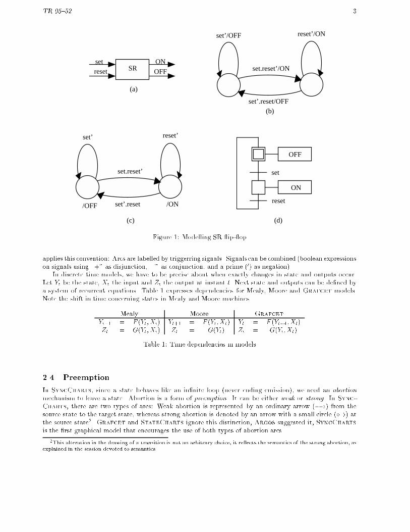
Up to now, when entering a state, the control remains in this state for at least one instant. A state issaid to be transient when it can be entered and left at the same instant. In Grafcet this behavior is notuncommon (transient activation of steps during a reaction). Transient states can be caused by immediatepreemptions. An immediate preemption by a signal s takes account of the strict future occurrences of s, aswell as the possible present occurrence.
# set
reset
OFF ON
Figure 5: Immediate preemption
SyncCharts allows both delayed and immediate occurrences. The former is the default option, thelatter requires a special pre�x \#" before the triggering expression.
Suppose that set and reset may occur simultaneously and that, in this case, set has priority overreset. Fig.5 captures this expected behavior.
2.11 Other features
SyncCharts has other possibilities not shown in the above examples. When a state can be preempted invarious ways, a priority is assigned to each outgoing arc, so that the behavior can be deterministic even iftriggering events are not exclusive.
3 Process Algebra
In this section we introduce an abstract and formal description of reactive behaviors. This terse form allowsprecise and concise expression of complex behaviors. People familiar with the Esterel's semantics are usedto this approach (see G. Berry's papers, e.g., [Ber92]).
3.1 Signals
A reactive system maintains permanent interactions with its environment by means of input and outputsignals. Let I be the set of input signals, and O the set of output signals of a reactive system. An inputevent is a subset I of I , an output event O is a subset of O . A Synchronous Reactive System (SRS)instantly reacts to input stimuli (input event I) by producing an output event O. An input history is asequence I1; I2; : : : ; In; : : : of input events, and an output history is a sequence of O1; O2; : : : ; On; : : : ofoutput events. The behavior of a SRS of sort fI;Og can be characterized by a mapping from input historiesinto output histories:
B : I��!O�
Let Sbe a set of signals. ? is a distinguished element of S; ? stands for a signal which is never present(the never occurring signal).
De�nition 1 (Process) A process on Sis de�ned recursively by:
TR 95{52 7
1. 0 (null)
2. s 2 (S� f?g) is a process on S, (emission)
3. If p and q are processes on S, then p j q is a process on S, (parallel)
4. If p is a process on S, then p� is a process on S (loop)
5. If p is a process on Sand s 2 (S� f?g), then p n s is a process on S, (restriction)
6. If p is a process on S, s 2 (S� f?g), and t 2S, then p [t=s] is a process on S, (renaming)
7. If p is a process on Sand s 2S, then s�� p is a process on S, (suspension)
8. If p; n; q are processes on Sand s 2S, then s% p � n; q is a process on S, (abortion)
The �rst process is useful to build derived constructors. The next four constructors are classical imperativeconstructors. The sixth constructor is usual in process calculus. Note that ? can't be renamed, but an inputsignal can be renamed into ?. The last two constructors are typically reactive.
Sort Transformations
Given p a process on S, we associate three disjoint subsets of Swith p: Ip;Op;Lp respectively called theinput, the output, the local sorts of p. Two auxiliary sets are introduced:
Xp = Ip [Op and Sp = Ip [Op [ Lp
Xp is the interface set of p, Sp is the sort of p.These sets are de�ned inductively as follows:
pp Xpp Opp Lpp0 ; ; ;s fsg fsg ;p j q Xp [ Xq Op [Oq ;p� Xp Op ;p n s Xp � fsg Op � fsg Lp [ fsgp [t=s] (s 2 Xp) Xp [t=s] Op [t=s] ;s�� p Xp [ fsg Op ;s% p � n; q Xp [ Xq [ Xn [ fsg Op [Oq [On ;
and for each operation:Ipp = Xpp �Opp and Spp = Xpp [ Lpp
Note that our renaming is restrictive: only an input or output signal of a process can be renamed, notlocal signals.
De�nition 2 (Event) An event E is a subset of Swithout the never occurring signal: E � S�f?g. Givena process p on S, I � Ip is an input event, O � Op is an output event.
3.2 Semantics
The semantics is expressed by a behavioral semantics. The behavior of a process is a deterministic mappingfrom input sequences to output sequences. A reaction is interpreted as a process rewriting.
Given a process p and an input sequence I1; I2; � � � ; In; � � �, the output sequence O1; O2; � � � ; On; � � � iscomputed as a chain of individual reactions:
p = p1I17�!O1
p2I27�!O2
� � �pnIn7�!On
pn+1 � � �

TR 95{52 8
A transition pnIn7�!On
pn+1 represents a single reaction. The pI7�!O
p0 relation is de�ned using an auxiliary
relation
pEp; b
���!E
p0
de�ned by structural induction over p. E is the set of signals that p sees as being present, Ep is the set ofsignals that p emits when receiving E, and b is a boolean (termination bit) such that b = tt if p terminatesand b = ff otherwise (p is said to wait).
The broadcasting invariant Ep � E must be maintained during all the derivations.Given a process p, an input event I:
pO7�!I
p0 i� pO; b���!O[I
p0 for some b
Rewriting Rules
0;;tt���!
E0 (null)
sfsg;tt����!
E0 (emission)
pEp; bp����!
Ep0 q
Eq; bq���!
Eq0
p j qEp[Eq ; bp^bq���������!
Ep0 j q0
(parallel)
pEp ;ff����!
Ep0
p �Ep;ff����!
E?% p0 � (p�); 0
(loop)
pEp; b
����!E[fsg
p0 s 2 Ep
p n sEp�fsg; b
������!E
p0 n s
(restr1)
pEp; b
����!E�fsg
p0 s 62 Ep
p n sEp; b
���!E
p0 n s
(restr2)
pEp; b
���!E
p0 s 2 Xp
p [t=s]Ep [t=s]; b������!
E [t=s]p0 [t=s]
(renam)
s 2 E
s�� p;;ff���!
Es�� p
(susp1)
s 62 E pEp;tt����!
Ep0
s�� pEp;tt����!
E0
(susp2)

TR 95{52 9
s 62 E pEp;ff����!
Ep0
s�� pEp;ff����!
Es�� p0
(susp3)
pEp;tt����!
Ep0 n
En; b���!
En0
s% p � n; qEp[En; b
������!E
n0(abort1)
s 2 E pEp;ff����!
Ep0 q
Eq; b
���!E
q0
s% p � n; qEp[Eq ; b
������!E
q0(abort2)
s 62 E pEp;ff����!
Ep0
s% p � n; qEp;ff����!
Es% p0 � n; q
(abort3)
Comments: We comment only three rules:
� (renam) short for renaming. p [t=s] is the process p in which each occurrence of s is replaced by t.E [t=s] =
�E � fsg
�[ ftg. As mentioned above, we rename only interface signals (s 2 Xp). There
exists another restriction: if t is ? then s must not be an output signal of p. In other words:
p [t=s] is de�ned for (s; t) 2�Ip �S
�[�Op � (S� f?g)
�� (abort1) states that if p terminates then n is started at the same instant: the normal termination of pis followed by n. If p does not terminate we have two cases:
{ Either s is present (abort2): p is aborted after its execution and q starts executing at the sameinstant; q can be seen as an exception handler.
{ Or s is absent (abort3): then p normally proceeds.
� (loop). Note that p (the body of the loop) should not terminate instantaneously.
Remark: This set of operators is not minimal. For instance, \0" could have been de�ned as \(s n s)".However, taking 0 as a primitive is simpler than deriving it from the somewhat complex restriction.
3.3 Derived constructors
For convenience and for compatibility with Esterel, new constructors are derived from the previous:
Derived imperative constructors
1 (pause)p; q (sequence)s?p; q (conditional)
They can be de�ned as:
1 � (s j (s�� 0)) n s
p; q � ?% p � q; 0
s?p; q � s% (s�� 0) � q; p
TR 95{52 10
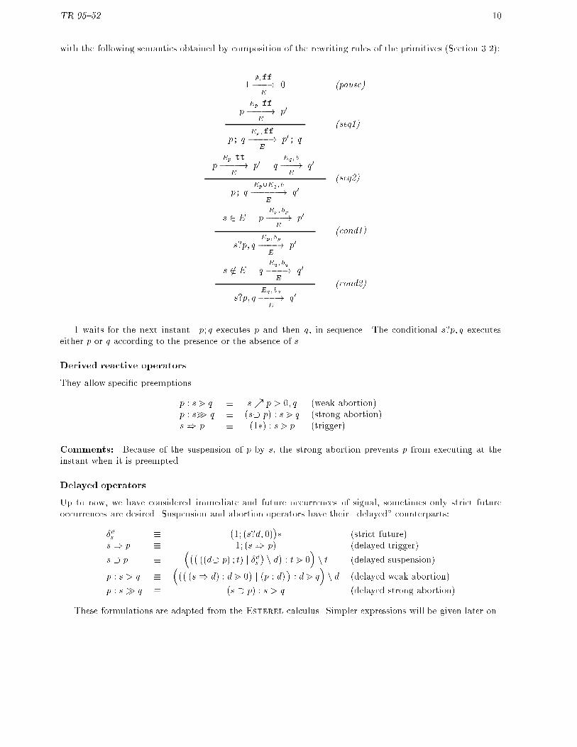
with the following semantics obtained by composition of the rewriting rules of the primitives (Section 3.2):
1;;ff���!
E0 (pause)
pEp;ff����!
Ep0
p; qEp;ff����!
Ep0; q
(seq1)
pEp;tt����!
Ep0 q
Eq; b
���!E
q0
p; qEp[Eq ; b
������!E
q0(seq2)
s 2 E pEp; bp����!
Ep0
s?p; qEp ; bp����!
Ep0
(cond1)
s 62 E qEq; bq���!
Eq0
s?p; qEq ; bq���!
Eq0
(cond2)
1 waits for the next instant. p; q executes p and then q, in sequence. The conditional s?p; q executeseither p or q according to the presence or the absence of s.
Derived reactive operators
They allow speci�c preemptions.
p : s m q � s% p � 0; q (weak abortion)p : sm> q � (s�� p) : s m q (strong abortion)s)� p � (1�) : s m p (trigger)
Comments: Because of the suspension of p by s, the strong abortion prevents p from executing at theinstant when it is preempted.
Delayed operators
Up to now, we have considered immediate and future occurrences of signal, sometimes only strict futureoccurrences are desired. Suspension and abortion operators have their \delayed" counterparts:
�ds ��1; (s?d; 0)
�� (strict future)
s) p � 1; (s)� p) (delayed trigger)
s � p ����
((d�� p) ; t) j �ds�n d�: tm 0
�n t (delayed suspension)
p : s > q ����
(s) d) : dm 0�j (p : d)
�: dm q
�n d (delayed weak abortion)
p : s� q � (s � p) : s > q (delayed strong abortion)
These formulations are adapted from the Esterel calculus. Simpler expressions will be given later on.

TR 95{52 11
Starting and termination signals
Two local signals \�; !"will be often associated with a process p: p � (�; p;!) n � n ! provided �; ! 62 Xp.
� � occurs at the very �rst instant of p activation,
� ! occurs at the termination of p.
For instance, the process that executes, after the termination of p, either q� if p terminates at its �rst instant,or q� otherwise, can be expressed as follows:
��; p; (�?q�; q�)
�.
3.4 Extending to compound signals
De�nition 3 (Compound signal) A compound signal on Sis de�ned recursively as follows:
� 8s 2 S, s is a compound signal on S,
� if �1 and �2 are compound signals on S, so are �1 + �2 and �1 � �2
� if � is a compound signal on S, so is �0
Notation 1 Let CSbe the set of the compound signals on S.
De�nition 4 (Truth value) The truth value associated with a compound � 2 CSfor a given e � S(noted[[� ]]e) is de�ned recursively as follows:
� 8s 2 S: [[ s ]]e = (s 2 e),
� 8�1; �2 2 CS: [[�1 + �2 ]]e = [[�1 ]]e _ [[�2 ]]e and [[�1 � �2 ]]e = [[�1 ]]e ^ [[�2 ]]e
� 8� 2 CS: [[�0 ]]e = :[[� ]]e
De�nition 5 (Satisfaction of a compound signal) An event e � S�f?g satis�es � 2 CS(noted e j= �)if [[� ]]e evaluates to tt.
De�nition 6 (Support of a compound signal) The support of � 2 CS(noted k�k ) is the set of thesignals occurring in �.
The rules for emission and restriction are extended to subset of signals; the rules for conditional, suspen-sion and abortion are extended to compound signals:
S for S � (S� f?g) (emission')p n S for S � (S� f?g) (restriction')�?p; q for � compound signal on S (conditional')��� p for � compound signal on S (suspension')� % p � n; q for � compound signal on S (abortion')
Let S = fs1; � � � ; sng. p n S ��� � � (p n s1) � � �
�n sn.
Other extensions behave according to the following rules:
SS;tt���!
E0 (emission')
E j= � pEp; bp����!
Ep0
�?p; qEp ; bp����!
Ep0
(cond1')

TR 95{52 12
E 6j= � qEq; bq���!
Eq0
�?p; qEq ; bq���!
Eq0
(cond2')
E j= �
��� p;;ff���!
E��� p
(susp1')
E 6j= � pEp;tt����!
Ep0
��� pEp;tt����!
E0
(susp2')
E 6j= � pEp;ff����!
Ep0
��� pEp;ff����!
E��� p0
(susp3')
pEp;tt����!
Ep0 n
En; b���!
En0
� % p � n; qEp[En; b
������!E
n0(abort1')
E j= � pEp;ff����!
Ep0 q
Eq; b
���!E
q0
�% p � n; qEp[Eq ; b
������!E
q0(abort2')
E 6j= � pEp;ff����!
Ep0
� % p � n; qEp;ff����!
Es% p0 � n; q
(abort3')
Remark: Compound signals allow simpler expressions of delayed operators:
s � p ��(�0 � s) �� (�; p)
�n� provided � 62 Xp (delayed suspension)
p : s > q ��(�; p) : (�0 � s) m q
�n � provided � 62 Xp (delayed weak abortion)
3.5 Generalized termination
3.5.1 Termination and Priority
A process p may either (normally) terminate, or be (weakly or strongly) aborted. A priority order can beassigned to those terminations.
We denoted the generalized termination by: p : �1 �1 q1; � � � ; �n �n qn where �1; � � � ; �n 2 fm; >;m>;�gFor at most one j, �j �j qj may be replaced by � qj, standing for the normal termination. If p can
normally terminate and no \� qj" term is provided, then we assume that there is an implicit \� 0" term atthe front of the termination list. This convention meets the one adopted for abortion in Sec.3.3:
s% p � 0; q � p : s m q is interpreted as p :� 0; sm q
Notation 2 (Highest priority) Given a list of compounds on Sarranged according to descending priority:
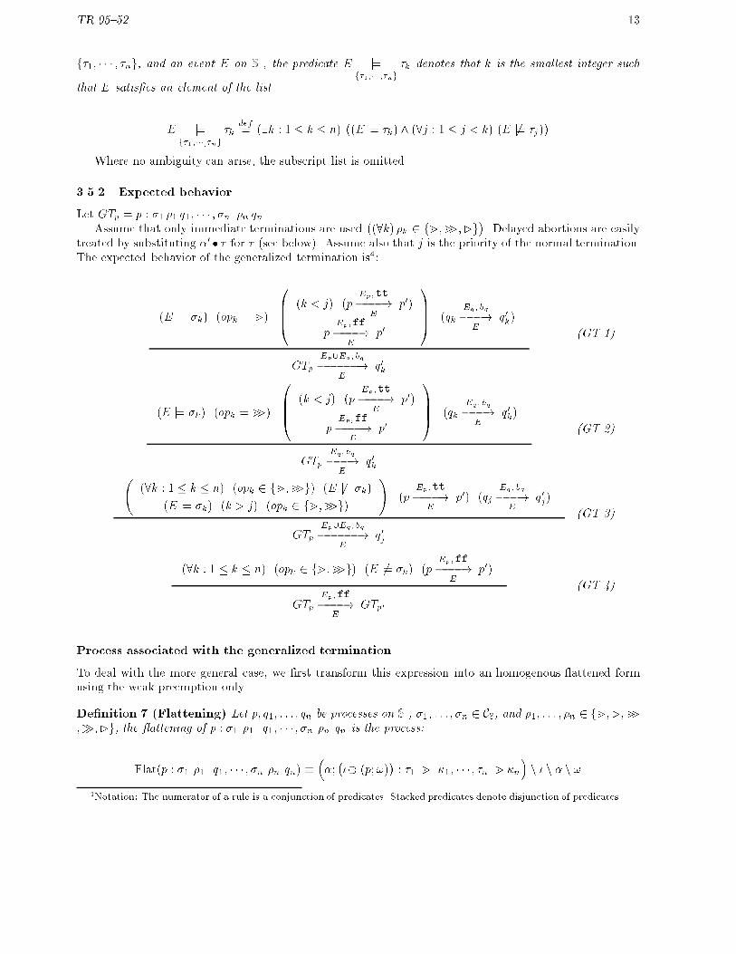
TR 95{52 13
f�1; � � � ; �ng, and an event E on S, the predicate \E j=f�1;���;�ng
�k denotes that k is the smallest integer such
that E satis�es an element of the list.
\E j=f�1;���;�ng
�kdef= (9k : 1 � k � n)
�(E j= �k) ^ (8j : 1 � j < k) (E 6j= �j)
�Where no ambiguity can arise, the subscript list is omitted.
3.5.2 Expected behavior
Let GTp = p : �1 �1 q1; � � � ; �n �n qn.Assume that only immediate terminations are used
�(8k) �k 2 fm;m>;�g
�. Delayed abortions are easily
treated by substituting �0 � � for � (see below). Assume also that j is the priority of the normal termination.The expected behavior of the generalized termination is4:
( \E j= �k) (opk = m)
0BB@ (k < j) (pEp;tt����!
Ep0)
pEp;ff����!
Ep0
1CCA (qkEq; bq���!
Eq0k)
GTpEp[Eq ; bq������!
Eq0k
(GT 1)
( \E j= �k) (opk = m>)
0BB@ (k < j) (pEp;tt����!
Ep0)
pEp;ff����!
Ep0
1CCA (qkEq ; bq���!
Eq0k)
GTpEq; bq���!
Eq0k
(GT 2)
(8k : 1 � k � n) (opk 2 fm;m>g) (E 6j= �k)
( \E j= �k) (k > j) (opk 2 fm;m>g)
!(p
Ep;tt����!
Ep0) (qj
Eq ; bq���!
Eq0j)
GTpEp[Eq; bq������!
Eq0j
(GT 3)
(8k : 1 � k � n) (opk 2 fm;m>g) (E 6j= �k) (pEp;ff����!
Ep0)
GTpEp;ff����!
EGTp0
(GT 4)
Process associated with the generalized termination
To deal with the more general case, we �rst transform this expression into an homogenous attened formusing the weak preemption only.
De�nition 7 (Flattening) Let p; q1; : : : ; qn be processes on S, �1; : : : ; �n 2 CS, and �1; : : : ; �n 2 fm; >;m>;�;�g, the attening of p : �1 �1 q1; � � � ; �n �n qn is the process:
Flat(p : �1 �1 q1; � � � ; �n �n qn) ���;���� (p;!)
�: �1 m �1; � � � ; �n m �n
�n � n � n !
4Notation: The numerator of a rule is a conjunction of predicates. Stacked predicates denote disjunction of predicates.
TR 95{52 14
provided �; �; ! 62
�Xp [
�k=nSk=1
Xqk
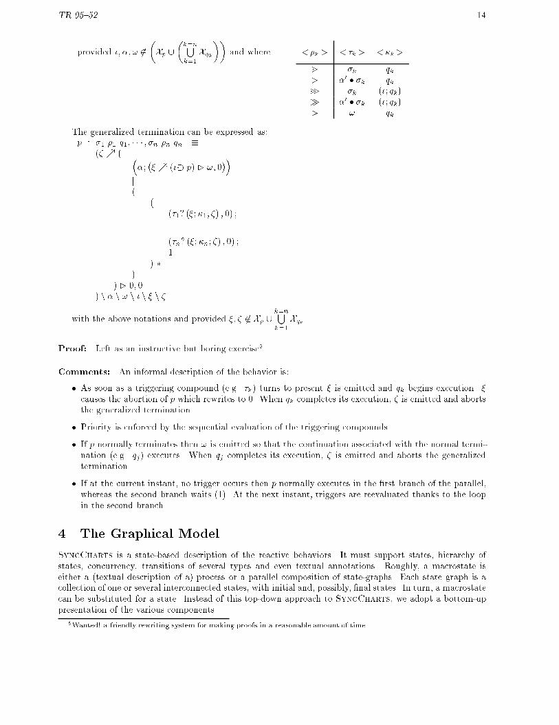
��and where <�k > <�k> <�k>
m �k qk> �0 � �k qkm> �k (�; qk)� �0 � �k (�; qk)� ! qk
The generalized termination can be expressed as:p : �1 �1 q1; � � � ; �n �n qn �
(� % ( ��;�� % (��� p) � !; 0
��j(
((�1? (�;�1; �) ; 0) ;
...(�n? (�;�n; �) ; 0) ;1
) �)
) � 0; 0) n � n ! n � n � n �
with the above notations and provided �; � 62 Xp [k=nSk=1
Xqk .
Proof: Left as an instructive but boring exercise5 .
Comments: An informal description of the behavior is:
� As soon as a triggering compound (e.g. �k) turns to present � is emitted and qk begins execution. �causes the abortion of p which rewrites to 0. When qk completes its execution, � is emitted and abortsthe generalized termination.
� Priority is enforced by the sequential evaluation of the triggering compounds.
� If p normally terminates then ! is emitted so that the continuation associated with the normal termi-nation (e.g. qj) executes. When qj completes its execution, � is emitted and aborts the generalizedtermination.
� If at the current instant, no trigger occurs then p normally executes in the �rst branch of the parallel,whereas the second branch waits (1). At the next instant, triggers are reevaluated thanks to the loopin the second branch.
4 The Graphical Model
SyncCharts is a state-based description of the reactive behaviors. It must support states, hierarchy ofstates, concurrency, transitions of several types and even textual annotations. Roughly, a macrostate iseither a (textual description of a) process or a parallel composition of state-graphs. Each state graph is acollection of one or several interconnected states, with initial and, possibly, �nal states. In turn, a macrostatecan be substituted for a state. Instead of this top-down approach to SyncCharts, we adopt a bottom-uppresentation of the various components.
5Wanted! a friendly rewriting system for making proofs in a reasonable amount of time.

TR 95{52 15
4.1 Graphical elements
4.1.1 Star
The graphical basic block is the state. In fact, this block is not only the expression of some local invariantbehavior (its body) but also a full description of the ways to leave this state. So, the basic block is botha classical state and its outgoing arcs (Fig. 6). We would rather call it a star (with outgoing arcs seen asbeams)6.
suspension
1
2
3
strong abortion
weak abortion
normal termination
priority
@body
s/e
w/f
i
/h
triggereffect
Figure 6: Basic Block: a Star
A star is drawn as a rounded rectangle with its \beams". Arcs are numbered according to a priorityordering (the less, the highest priority). The weak abortion is expressed by a plain arrow (�!). The normaltermination, i.e., leaving the star because its body terminates, is drawn as an arrow with a leading triangle(�!). The suspension is denoted by a special dangling incoming arc with a circle head ((). The strongabortion which is a combination of weak abortion and suspension, is speci�ed by an hybrid arrow (�!).
A star with n outgoing arcs (n beams) is said to be a n-star. There exists a special kind of star with nobeam. It is a 0-star. There is no way to leave a 0-star but by a higher level abortion.
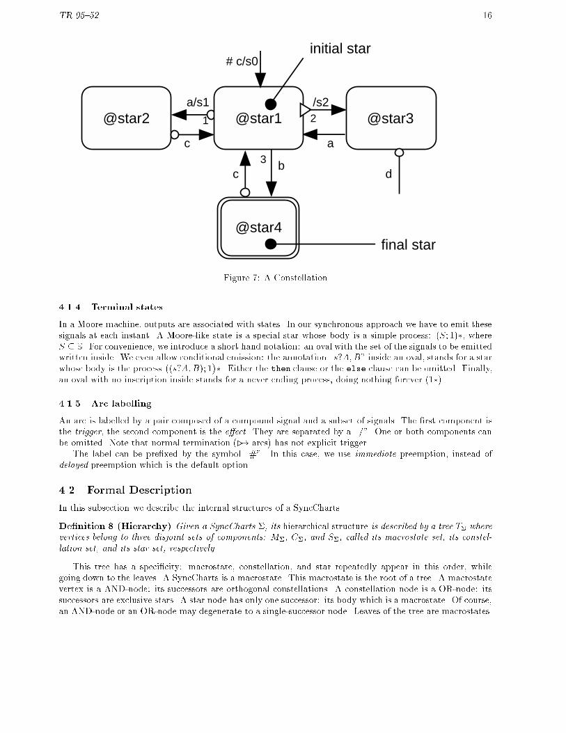
4.1.2 Constellation
States are interconnected to make a state graph; Stars are interconnected to make a constellation. Figure 7shows an instance of a constellation with one initial star and one �nal star. There may be 0, 1 or several �nalstars. Final stars are distinguished by double-line rounded rectangles. There must be at least one initialstar. Initial stars are identi�ed by a dangling incoming arrow. A constellation need not be a connectedgraph. A constellation can be made of a single 0-star which is implicitly an initial star.
A constellation made of n stars is said to be a n-constellation.
4.1.3 Macrostate
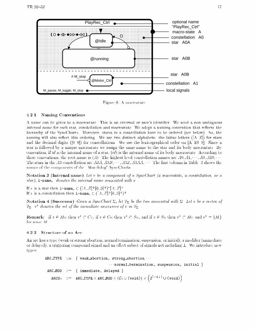
A parallel composition of constellations is a �rmament or a macrostate7. The components are delimited bydashed lines. There may be a single constellation in a macrostate. In this case, dashed lines are omitted. Amacrostate may have local signals. A macrostate has an optional name. It is drawn as a rounded rectanglewith a header in which the optional name is written. See Fig. 8.
A macrostate with n orthogonal constellation is said to be a n-macrostate.
6Reactive systems have been compared to cacti, in our opinion stars are less aggressive and more poetical.7Firmament is a nice word whose etymology \�rmamentum" means \support" (the vault on which stars are �xed). Contrary
to star and constellation used elsewhere in mathemathics, �rmament is not usual; We shall refer to as macrostate instead.
TR 95{52 16
2
3
1
initial star
final star
b
a/s1 /s2
c
c d
a
@star1
@star4
@star2 @star3
# c/s0
Figure 7: A Constellation
4.1.4 Terminal states
In a Moore machine, outputs are associated with states. In our synchronous approach we have to emit thesesignals at each instant. A Moore-like state is a special star whose body is a simple process: (S; 1)�, whereS � S. For convenience, we introduce a short hand notation: an oval with the set of the signals to be emittedwritten inside. We even allow conditional emission: the annotation \s?A;B" inside an oval, stands for a starwhose body is the process
�(s?A;B); 1
��. Either the then clause or the else clause can be omitted. Finally,
an oval with no inscription inside stands for a never ending process, doing nothing forever (1�).
4.1.5 Arc labelling
An arc is labelled by a pair composed of a compound signal and a subset of signals. The �rst component isthe trigger, the second component is the e�ect. They are separated by a \/". One or both components canbe omitted. Note that normal termination (�! arcs) has not explicit trigger.
The label can be pre�xed by the symbol \#". In this case, we use immediate preemption, instead ofdelayed preemption which is the default option.
4.2 Formal Description
In this subsection we describe the internal structures of a SyncCharts.
De�nition 8 (Hierarchy) Given a SyncCharts �, its hierarchical structure is described by a tree T� wherevertices belong to three disjoint sets of components: M�, C�, and S�, called its macrostate set, its constel-lation set, and its star set, respectively.
This tree has a speci�city: macrostate, constellation, and star repeatedly appear in this order, whilegoing down to the leaves. A SyncCharts is a macrostate. This macrostate is the root of a tree. A macrostatevertex is a AND-node: its successors are orthogonal constellations. A constellation node is a OR-node: itssuccessors are exclusive stars. A star node has only one successor: its body which is a macrostate. Of course,an AND-node or an OR-node may degenerate to a single-successor node. Leaves of the tree are macrostates.
TR 95{52 17
AAAAAAAAAAAAAAAAAAAAAAAAAAAAAAAAAAAAAAAAAAAAAAAAAAAAAAAAAAAAAAAAAAAAAAAAAAAAAAAAAAAA
PlayRec_Ctrl
@Motor_Ctrl
@Idle
M_pause, M_toggle, M_stop
# M_stop
@running
optional name “PlayRec_Ctrl”
constellation A0
constellation A1
local signals
star A0A
star A0B
star A0B
macro-state A
Figure 8: A macrostate
4.2.1 Naming Conventions
A name can be given to a macrostate. This is an external or user's identi�er. We need a non ambiguousinternal name for each star, constellation and macrostate. We adopt a naming convention that re ects thehierarchy of the SyncCharts. Moreover, states in a constellation have to be ordered (see below). So, thenaming will also re ect this ordering. We use two distinct alphabets: the latine letters ([A..Z]) for starsand the decimal digits ([0..9]) for constellations. We use the lexicographical order on [A..Z0..9]. Since astar is followed by a unique macrostate we assign the same name to the star and its body macrostate. Byconvention, if id is the internal name of a star, (id) is the internal name of its body macrostate. According tothese conventions, the root name is (A). The highest level constellation names are A0; A1; � � � ; A9; A10; � � �.The stars in the A3 constellation are A3A;A3B; � � � ; A3Z;A3AA; � � �. The �rst colomn in Table. 3 shows thenames of the components of the \Watchdog" SyncCharts.
Notation 3 (Internal name) Let v be a component of a SyncChart (a macrostate, a constellation, or astar), i-namev denotes the internal name associated with v.
If v is a star then i-namev 2 ([A::Z]+[0::9]+)�[A::Z]+.If v is a constellation then i-namev 2 ([A::Z]+[0::9]+)+.
Notation 4 (Successor) Given a SyncChart �, let T� be the tree associated with �. Let v be a vertex ofT�. v� denotes the set of the immediate successors of v in T�.
Remark: if v 2 M� then v� � C�, if v 2 C� then v� � S�, and if v 2 S� then v� � M� and v� = fMgfor some M .
4.2.2 Structure of an Arc
An arc has a type (weak or strong abortion, normal termination, suspension, or initial), a modi�er (immediateor delayed), a triggering compound signal and an e�ect subset of signals not including ?. We introduce newtypes:
ARC TYPE ::= f weak abortion, strong abortion; � � �
� � �normal termination, suspension, initial g
ARC MOD ::= f immediate, delayed g
ARCSS ::= ARC TYPE� ARC MOD� (CS[ (void)) ��2S�f?g[ (void)
�

TR 95{52 18
Notation 5 (Arc) Let a 2 ARCS. a = <atyp; amod; atrig; aeff >.
Subtypes are distinguished for ARCSS:
� ARCSsuspS
for suspension arcs, such that 8a 2 ARCSsuspS
:
atyp = suspension; atrig is not (void) ; aeff is (void)
� ARCSnormS
for normal termination arcs, such that 8a 2 ARCSnormS
:
atyp = normal termination; amod = immediate; atrig is (void) ; aeff is not (void)
� ARCSinitS
for initial arcs, such that 8a 2 ARCSinitS
:
atyp = initial; amod = immediate
� ARCSabortS
for transition arcs, such that 8a 2 ARCSabortS
:
atyp 2 fweak abortion, strong abortiong; atrig is not (void) ; aeff is not (void)
4.2.3 Structure of a Macrostate
Let M be a macrostate of a SyncCharts �. Either M is the root and its internal name is (A), or M is thebody of some star S and i-nameM = (i-nameS).
Information attached to a macrostate M
� NameM (optional identi�er)
� LocalM � (S� f?g) (local signals)
� M� � C� (set of constellation components)
Constraint
� M� 6= ;
Signal sets of M
LM = LocalM [
[c2M�
f!cg
!provided
[c2M�
!c
!\
[c2M�
Xc
!= ;
XM =
[c2M�
Xc
!� LM
OM =
[c2M�
Oc
!�LM
IM = XM � OM
Remark: Signals !c are emitted by the constellation components and are used for the termination of themacrostate. !c is present whenever constellation c is in a �nal star. These internal signals are hidden fromthe user.

TR 95{52 19
4.2.4 Structure of a Constellation
Let C be a constellation of a SyncCharts �.
Information attached to a constellation C
� C� � S� (set of the component stars)
� in-degreeC 2 IN (number of initial arcs)
� �C :
� Ss2C�
(fsg � [1::out-degrees])
��!C� (connections)
� �iC : [1::in-degreeC ]�!ARCSinitS�C� (initial arcs)
� �fC � C� (�nal stars)
Constraint
� in-degreeC � 1
Signal sets of C
LC =[
s2C�
f sg provided s 62[
k2C�
Xk
XC =
[s2C�
Xs
![ f!Cg provided !C 62
[s2C�
Xs
OC =
[s2C�
Os
![ f!Cg
IC = XC �OC
Remark: The signals !C and s are emitted by C. !C is used for the synchronized termination of parallelconstellation. s is used to pass the control from a star to another star. s can be interpreted as \go to stars". These internal signals are hidden from the user.
4.2.5 Structure of a Star
Let S be a star of a SyncCharts �.
Information attached to a star S
� BodyS 2M� such that S� = fBodySg (body of S)
� out-degreeS 2 IN (number of beams)
� InhibitS 2 ARCSsuspS
(suspension)
� BeamsS : [1::out-degreeS ]�!�ARCSabortS
[ ARCSnormS
�(outgoing arcs)
Constraint
� There is at most one k � out-degreeS such that BeamsS(k) 2 ARCSnormS
.

TR 95{52 20
Signal sets of C Let p be the body of S (fpg = S�), h be InhibitS , and n be out-degreeS . S is an-star.
LS = f�; !; �g provided �; !; � 62 Xp
XS = Xp [ khtrigk [
0BB@ [k2[1::n]
a=BeamsS [k]
�katrigk [ kaeffk [ f�kg
�1CCA provided �k 62 Xp
OS = Op [
0BB@ [k2[1::n]
a=BeamsS [k]
�kaeffk [ f�kg
�1CCAIS = XS � OS
Remark: The signals �, !C , �, and �k are emitted by S and they are used for internal synchronization.� is a signal that causes the inhibition (the suspension) of the body. �k (eXit signal) is the signal emittedwhen leaving the star S through the beam whose priority is k. These internal signals are hidden from theuser.
4.3 Example
Fig.9 shows the structuration of the Watchdog application (Section.2.8).
Table 3: Components of the SyncCharts that specifies Watchdog
i-name type modif IN ON LNA0B0A0A 1-star I fc2g fb02g ;A0B0A0B 1-star F fc2g fb2g ;A0B0A0 2-const. fc2g fb02; b2g ;A0B0A1A 1-star I fc1g fb01g ;A0B0A1B 1-star F fc1g fb1; c2g ;A0B0A1 2-const. fc1g fb01; b1; c2g ;A0B0A2A 1-star I fc0g fb00g ;A0B0A2B 1-star F fc0g fb0; c1g ;A0B0A2 2-const. fc0g fb00; b0; c1g ;(A0B0A) 3-macro fc0g fb02; b2; b
01; b1; b
00; b0g fc2; c1g
A0B0A 1-star I,S fc0; Inhibg fb02; b2; b01; b1; b
00; b0g ;
A0B0B 0-star ; fAlarmg ;A0B0 2-const. fc0; Inhibg fb02; b2; b
01; b1; b
00; b0; Alarmg ;
A0B 1-star fc0; Inhib; resetg fb02; b2; b01; b1; b
00; b0; Alarmg ;
AOA 1-star I fsetg ; ;A0 2-const. fc0; Inhib; reset; setg fb02; b2; b
01; b1; b
00; b0; Alarmg ;
A 0-star I fc0; Inhib; reset; setg fb02; b2; b01; b1; b
00; b0; Alarmg ;
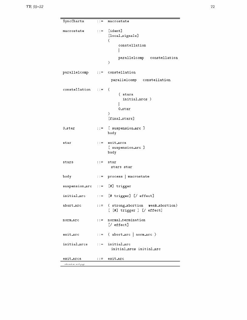
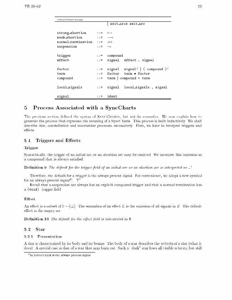
4.4 Grammar
Table 4: Grammar of SyncCharts

TR 95{52 21
star A0A
set
macrostate (A) constellation A0
reset
star A0B
AAAAAAAAA
body A0B
A B
A B
constellation A0B0
Inhib
star A0B0A
Alarm
0-star A0B0B
AAAAAAAAA
body A0B0A
A B
A B
A B
constellations A0B0A0,A0B0A1,A0B0A2
[ local c1,c2 ]
b1’
b1
star A0B0A1A
star A0B0A1B
c1/c2
c1AAA
AAA
.........
.........
.........
.........
watchdog
(A0B)
(A0B0A)
Figure 9: Structuration of Watchdog
TR 95{52 22
SyncCharts ::= macrostate
macrostate ::= [ident]
[local signals]
(
constellation
j
parallelcomp... constellation
)
parallelcomp ::= constellation
j parallelcomp... constellation
constellation ::= (
( stars
initial arcs )
j0 star
)
[final stars]
0 star ::= [ suspension arc ]
body
star ::= exit arcs
[ suspension arc ]
body
stars ::= star
j stars star
body ::= process j macrostate
suspension arc ::= [#] trigger
initial arc ::= [# trigger] [/ effect]
abort arc ::= ( strong abortion j weak abortion)
[ [#] trigger ] [/ effect]
norm arc ::= normal termination
[/ effect]
exit arc ::= ( abort arc j norm arc )
initial arcs ::= initial arc
j initial arcs initial arc
exit arcs ::= exit arc
continued on next page
TR 95{52 23
continued from previous page
j exit arcs exit arc
strong abortion ::= �!weak abortion ::= �!normal termination ::= �!suspension ::= (
trigger ::= compound
effect ::= signal j effect , signal
factor ::= signal j signal' j ( compound )'
term ::= factor j term � factor
compound ::= term j compound + term
local signals ::= signal j local signals , signal
signal ::= ident
5 Process Associated with a SyncCharts
The previous section de�ned the syntax of SyncCharts, but not its semantics. We now explain how togenerate the process that expresses the meaning of a SyncCharts. This process is built inductively. We shalldescribe star, constellation and macrostate processes successively. First, we have to interpret triggers ande�ects.
5.1 Triggers and E�ects
Trigger
Syntactically, the trigger of an initial arc or an abortion arc may be omitted. We interpret this omission asa compound that is always satis�ed.
De�nition 9 The default for the trigger �eld of an initial arc or an abortion arc is interpreted as ?0
Therefore, the default for a trigger is the always present signal. For convenience, we adopt a new symbolfor an always present signal8: \>".
Recall that a suspension arc always has an explicit compound trigger and that a normal termination hasa (void) trigger �eld.
E�ect
An e�ect is a subset of S�f?g. The semantics of an e�ect E is the emission of all signals in E. The defaulte�ect is the empty set.
De�nition 10 The default for the e�ect �eld is interpreted as ;
5.2 Star
5.2.1 Presentation
A star is characterized by its body and its beams. The body of a star describes the activity of a star (what itdoes). A special case is that of a star that may burn out. Such a \dark" star loses all visible activity, but still
8In Esterel tick is the always present signal.

TR 95{52 24
exists. On the contrary, a star can be destroyed (either externally enforced destruction, or self-destruction).Beams represent potential destructions of the star.
The activity of a star may also be suspended (it is only an eclipse, not a permanent extinction).
5.2.2 Expected behavior of a star
The behavior of a star is akin to a generalized termination (Section 3.5) in which handlers are instantaneousprocesses that, possibly, emit signals. Nevertheless, there are two di�erences: the activity of a star can besuspended by a triggering compound, and the continuation after the normal termination of the body of thestar can be absent.
Let p be the body of the star, �0 be its suspending triggering compound, �1 �1 �1; � � � ; �n �n �n be itstermination list. The terms �k �k �k are arranged according to descending priority of the beams. �k (�k)is the trigger (the e�ect, resp.) of the kth beam. �1; � � � ; �n 2 fm; >;m>;�;�g and �nally, �0 2 f��;�gcharacterizes the type of suspension.
Given a star S, STARS(p) denotes the process associated with S, where p is the body of S. Unlike the� 's, the �'s and the �'s which are static information, p changes during the life of the star. That is the reasonwhy p is used as a parameter.
Without loss of generality, assume that only immediate operators are used. If there is no normal termi-nation j is set to n + 1, otherwise j is assigned the priority index of the unique normal termination. Theexpected behavior of the star is:
(\E j= �k) (�k = m)
0BBBBBBBB@(E 6j= �0)
0BBBB@(k < j) (p
Ep;tt����!
Ep0)
(pEp ;ff����!
Ep0)
1CCCCA(E j= �0) (Ep = ;)
1CCCCCCCCASTARS(p)
Ep[�k[f�kg;tt�����������!
E0
(Star 1)
(\E j= �k) (�k = m>)
0BBBBBBBB@(E 6j= �0)
0BBBB@(k < j) (p
Ep ;tt����!
Ep0)
(pEp;ff����!
Ep0)
1CCCCA(E j= �0)
1CCCCCCCCASTARS(p)
�k[f�kg;tt��������!
E0
(Star 2)
0@ (8k : 1::n) (�k 2 fm;m>g) (E 6j= �k) (j � n)
(\E j= �k) (k > j) (�k 2 fm;m>g)
1A (E 6j= �0) (pEp;tt����!
Ep0)
STARS (p)Ep[�j[f�jg;tt����������!
E0
(Star 3)
(8k : 1::n) (�k 2 fm;m>g) (E 6j= �k) (E j= �0)
STARS(p);;ff���!
ESTARS(p)
(Star 4)
TR 95{52 25
(8k : 1::n) (�k 2 fm;m>g) (E 6j= �k) (E 6j= �0) (pEp ;ff����!
Ep0)
STARS(p)Ep;ff����!
ESTARS (p
0)
(Star 5)
(8k : 1::n) (�k 2 fm;m>g) (E 6j= �k) (E 6j= �0) (pEp;tt����!
Ep0) (j > n)
STARS (p)Ep ;ff����!
ESTARS(1�)
(Star 6)
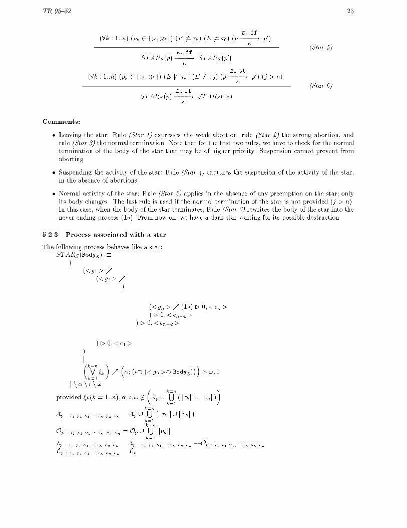
Comments:
� Leaving the star: Rule (Star 1) expresses the weak abortion, rule (Star 2) the strong abortion, andrule (Star 3) the normal termination. Note that for the �rst two rules, we have to check for the normaltermination of the body of the star that may be of higher priority. Suspension cannot prevent fromaborting.
� Suspending the activity of the star: Rule (Star 4) captures the suspension of the activity of the star,in the absence of abortions.
� Normal activity of the star: Rule (Star 5) applies in the absence of any preemption on the star; onlyits body changes. The last rule is used if the normal termination of the star is not provided (j > n).In this case, when the body of the star terminates, Rule (Star 6) rewrites the body of the star into thenever ending process (1�). From now on, we have a dark star waiting for its possible destruction.
5.2.3 Process associated with a star
The following process behaves like a star:STARS(BodyS) �
((<g1>%
(<g2>%(
...(<gn>% (1�) � 0; <en>) � 0; < en�1>
) � 0; < en�2>...
) � 0; < e1>)j�k=nWk=1
�k
�%��;���� (<g0>�� BodyS)
��� !; 0
) n � n � n !
provided �k(k = 1::n); �; �; ! 62
�Xp [
k=nSk=1
(k�kk [ k�kk)
�Xp : �1 �1 �1;���;�n �n �n = Xp [
k=nSk=1
(k�kk [ k�kk)
Op : �1 �1 �1;���;�n �n �n = Op [k=nSk=1k�kk
Ip : �1 �1 �1;���;�n �n �n = Xp : �1 �1 �1;���;�n �n �n � Op : �1 �1 �1;���;�n �n �n
Lp : �1 �1 �1;���;�n �n �n = Lp
TR 95{52 26
where �0 <g0>�� �0� �0 � �0�k <gk> <ek>m � 01 � � � � � �
0k�1 � �k �k; �k
> �0 � � 01 � � � � � �0k�1 � �k �k; �k
m> � 01 � � � � � �0k�1 � �k �; �k; �k
� �0 � � 01 � � � � � �0k�1 � �k �; �k; �k
� � 01 � � � � � �0k�1 � ! �k; �k
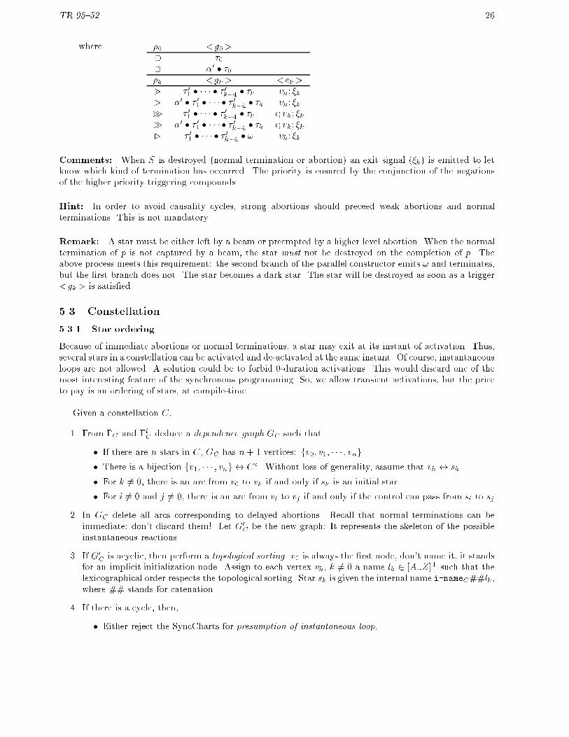
Comments: When S is destroyed (normal termination or abortion) an exit signal (�k) is emitted to letknow which kind of termination has occurred. The priority is ensured by the conjunction of the negationsof the higher priority triggering compounds.
Hint: In order to avoid causality cycles, strong abortions should preceed weak abortions and normalterminations. This is not mandatory.
Remark: A star must be either left by a beam or preempted by a higher level abortion. When the normaltermination of p is not captured by a beam, the star must not be destroyed on the completion of p. Theabove process meets this requirement: the second branch of the parallel constructor emits ! and terminates,but the �rst branch does not. The star becomes a dark star. The star will be destroyed as soon as a trigger<gk> is satis�ed.
5.3 Constellation
5.3.1 Star ordering
Because of immediate abortions or normal terminations, a star may exit at its instant of activation. Thus,several stars in a constellation can be activated and de-activated at the same instant. Of course, instantaneousloops are not allowed. A solution could be to forbid 0-duration activations. This would discard one of themost interesting feature of the synchronous programming. So, we allow transient activations, but the priceto pay is an ordering of stars, at compile-time.
Given a constellation C,
1. From �C and �iC deduce a dependence graph GC such that
� If there are n stars in C, GC has n+ 1 vertices: fv0; v1; � � � ; vng.
� There is a bijection fv1; � � � ; vng $ C�. Without loss of generality, assume that vk $ sk.
� For k 6= 0, there is an arc from v0 to vk if and only if sk is an initial star.
� For i 6= 0 and j 6= 0, there is an arc from vi to vj if and only if the control can pass from si to sj
2. In GC delete all arcs corresponding to delayed abortions. Recall that normal terminations can beimmediate: don't discard them!. Let G0
C be the new graph: It represents the skeleton of the possibleinstantaneous reactions.
3. If G0C is acyclic, then perform a topological sorting. v0 is always the �rst node, don't name it, it stands
for an implicit initialization node. Assign to each vertex vk, k 6= 0 a name lk 2 [A::Z]+ such that thelexicographical order respects the topological sorting. Star sk is given the internal name i-nameC##lk,where ## stands for catenation.
4. If there is a cycle, then,
� Either reject the SyncCharts for presumption of instantaneous loop,

TR 95{52 27
� Or consider further details in order to erase an arc involved in a cycle. For example you can deducefrom the inspection of the body of a star that its normal termination is never at its activationtime.
See example of application in Fig. 10. Vertex v0 is a solid circle. Since the translation process heavilydepends on the order of stars in a constellation, be sure not to make unjusti�ed deletions.
A 7-constellation
eM52
#eM51eM11
#eM12
#eM13
eM23#eM21
eM22
eM61
eM62
eM7
eM32#eM31
#eM41 eM42
1 2
3 4
5 6
7
#c #c’
1
2
1
2
3
12
3
1
2
21
1 2
eM1012
Potential Instantaneous Transition Graph
E A
F B
G C
D
Figure 10: Ordering stars in a constellation
5.3.2 Expected behavior of a constellation
Given a constellation C,
� Let n be the number of stars in C (cardinality of C�).
� Let l be the number of initial stars in C (in-degreeC). Recall that l � 1.
� Let �iC(k) = <Ik ; sk > (k = 1::l) where Ik 2 ARCSinitS
and sk 2 C�. Note that Ik1 has priority overIk2 if k1 < k2.
� Let �C(s; k) =� s; k� where s 2 C�; k 2 [1::�s] where �s = out-degrees, and � s; k� 2 C�.
We impose a new semantic constraint on a constellation:
Constraint
��8E � (S� ?)
�[[k=lWk=1
(Ik)trig ]]E = tt
This constraint means that at least one initial arc has a trigger evaluated to tt, so that there is always atleast one eligible initial star.

TR 95{52 28
Hint: Use a void trigger for the default initial arc. The semantic constraint on the initial arc labeling willbe always ful�lled.
The process CONSTC(k; p) associated with C has two parameters: the index of the active star and thecurrent body of this star. Initially, we have CONST (0; 0). After an initialization phase, CONSTC enters anever ending loop.
Initialization phase: The �rst active star in the constellation C is the elegible star with the highestpriority. Let k be this star (1 � k � l). The expected behavior is:
(9k : 1::l)�E j= (Ik)trig
�^�(8j < k) E 6j= (Ij)trig
�CONSTC(0; 0)
f kg;tt�����!
ECONSTC(k; Bodyk)
(Const 1)
Comments: 1; � � � ; n are signals local to C. k is interpreted as goto star k.
Comments:
� The initialization emits one and only one signal: k such that k 2 [1::l] is the least integer such thatE j= (Ik)trig where E is the current event.
� The least priority initial arc (�iC(l)) is used as the default initial arc: If for all k < l, E 6j= (Ik)trig,then (Il)trig must be satis�ed. The constraint imposed on the initial arc labeling ensures that, in thiscase, E j= (Il)trig and there is no need for evaluating it, at run-time.
A process for the initialization part :CONSTC(0; 0) ::=
(I1)trig?� 1; (I1)eff
�;�
(I2)trig?� 2; (I2)eff
�;�
. . .
(Il�1)trig?� l�1; (Il�1)eff
�;�
l; (Il)eff�...��
;LOOPC
The Loop part: The idea is to optionally execute stars ordered according to the topological sorting insequence and repeatedly. The goto's signals are used to decide whether a star has to be activated or not.
Beside the activity of a star, we have to emit the !C signal if and only if the active star is a �nal starthat will not be aborted at the current instant.
Expected behavior of the loop part:
( k 2 E)�STARk(Bodyk)
Ek;tt����!
E0�
(�i 2 Ek)��C(k; i) = j
�CONSTC(k; Bodyk)
Ek [ j=�i ];tt���������!
ECONSTC(j; Bodyj)
(Const 2)

TR 95{52 29
( k 2 E)�STARk(Bodyk)
Ek ;ff����!
ESTARk(p)
� 0@ (k 2 �fC) (F = f!Cg)
(k 62 �fC) (F = ;)
1ACONSTC (k; Bodyk)
F[Ek [ j=�i ];ff�����������!
ECONST �
C(k; p)
(Const 3)
�STARk(p)
Ek;ff����!
ESTARk(p0)
� 0@ (k 2 �fC) (F = f!Cg)
(k 62 �fC) (F = ;)
1ACONST �
C(k; p)F[Ek;ff������!
ECONST �
C (k; p0)
(�-Const 1)
�STARk(p)
Ek;tt����!
E0�
(�i 2 Ek)��C(k; i) = j
�CONST �
C (k; p)Ek [ j=�i];tt���������!
ECONST �
C(j; Bodyj)
(�-Const 2)
Comments:
� Rule (Const 2) captures the instantaneous execution of the star k that emits one and only one exit signal(say �i). This signal is renamed in a goto signal ( j) according to the connections in the constellationC (�C(k; i) = j). The control is immediately passed to the star j.
� If the star k does not immediately terminate, then rule (Const 3) applies. CONSTC (k; Bodyk) rewritesinto CONST �
C(k; p), the superscript � denotes that it is no longer the �rst instant of CONSTC(k; Bodyk).
The parameter p keeps trace of the changes in the star k. Moreover, if k is a �nal star (k 2 �fC), thensignal !C is emitted.
� Rule (�-Const 1) stands for the normal activity of star k. Here again, if k is a �nal star then signal!C is emitted.
� Finally, rule (�-Const 2) corresponds to the abortion of star k not in its �rst instant. One and onlyone exit signal �i is emitted, seen as a goto signal j . The star j is immediately activated. Note thatin the case of a �nal star k, !C is no longer emitted since the star k is aborted.
A process for the loop part: We need a loop in which we can enter at any point, then proceed on insequence or restart from the beginning. A sequence of conditionals, weakly aborted by a local signal withina loop will do: ���
( 1?CSTAR1; 0); � � � ; ( n?CSTARn; 0)�: �m 0
�n ���
where � is emitted when a star terminates at an instant which is not its activation instant; CSTARk isa process derived from STARk augmented with the management of the !C signal.
A possible process is:

TR 95{52 30
LOOPC ::=((( �
1?���;CSTAR1; (�?0; �)
�n ��; 0�;
...� n?���;CSTARn; (�?0; �)
�n ��; 0�;
) n �)�
where CSTARk
::= ( ��(!C ; 1) �
�: !m> 0
�j (if sk 2 �fC)�STARk(Bodyk) [ �k;1�=�1; � � � ; � k;�k�=��k ];!
�) n !
::= STARk(Bodyk) [ � k;1�=�1; � � � ; � k;�k�=��k] (otherwise)
5.4 Macrostate
5.4.1 Presentation
Recall that a SyncCharts is a macrostate. A macrostate is composed of orthogonal constellations. Amacrostate delimits the scope of user's de�ned local signals. A macrostate has also to manage the synchro-nized termination of its constellation components.
5.4.2 Expected behavior of a macrostate
Let M be a n-macrostate. Let c1; c2; : : :; cn be its constellation components. Let L � LM a subset of theset of the local variables of M . Let !M = f!c1 � � � ��g!cn, whereg!ck is egal to either !ck or !0ck. We introduceauxiliary notations:
!+M = f!ck j !ck appears in its direct form in !Mg
!�M = f!ck j !ck appears in its complementary form in !Mg
~E =�E [ !+
M
�� !�M
�L = LM � L
The process associated with the macrostate M has 2 � n parameters that characterize its state (i.e.,the state of each constellation component): MACROM
�(k1; p1); � � � ; (kn; pn)
�. The expected behavior of a
macro is de�ned by the following rules:
(L �j=nSj=1
Ej) (!M 6= !c1 � � � � � !cn)
CONSTcj(kj; pj)
Ej ; bj������!( ~E[L)��L
CONSTck(k0j; p
0j)
!j=n
j=1
MACROM
�(k1; p1); � � � ; (kn; pn)
� k=nSk=1
Ek
!�L�!+
M;ff
���������������!E
MACROM
�(k01; p
01); � � � ; (k
0n; p
0n)�
(Macro 1)
TR 95{52 31
(L �j=nSj=1
Ej) (!M = !c1 � � � � � !cn)
CONSTcj(kj; pj)
Ej ; bj������!( ~E[L)��L
CONSTck(k0j; p0j)
!j=n
j=1
MACROM
�(k1; p1); � � � ; (kn; pn)
� k=nSk=1
Ek
!�L�!+
M;tt
���������������!E
0
(Macro 2)
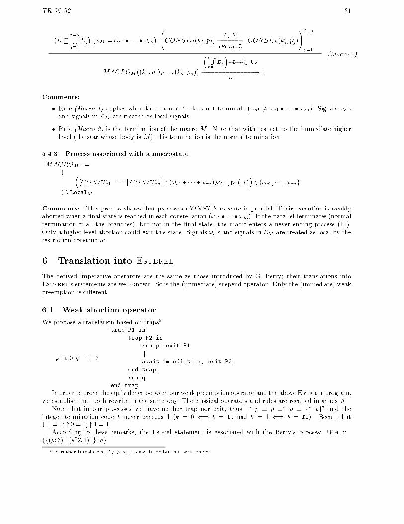
Comments:
� Rule (Macro 1) applies when the macrostate does not terminate (!M 6= !c1 � � � � � !cn). Signals !c'sand signals in LM are treated as local signals.
� Rule (Macro 2) is the termination of the macro M . Note that with respect to the immediate higherlevel (the star whose body is M ), this termination is the normal termination.
5.4.3 Process associated with a macrostate
MACROM ::=( ��
CONSTc1 j � � � j CONSTcn�:�!c1 � � � � � !cn
�m> 0;� (1�)
�n f!c1; � � � ; !cng
) n LocalM
Comments: This process shows that processes CONSTc's execute in parallel. Their execution is weaklyaborted when a �nal state is reached in each constellation (!c1 � � � ��!cn). If the parallel terminates (normaltermination of all the branches), but not in the �nal state, the macro enters a never ending process (1�).Only a higher level abortion could exit this state. Signals !c's and signals in LM are treated as local by therestriction constructor.
6 Translation into Esterel
The derived imperative operators are the same as those introduced by G. Berry; their translations intoEsterel's statements are well-known. So is the (immediate) suspend operator. Only the (immediate) weakpreemption is di�erent.
6.1 Weak abortion operator
We propose a translation based on traps9.
p : s m q ()
trap P1 in
trap P2 in
run p; exit P1
kawait immediate s; exit P2
end trap;
run q
end trapIn order to prove the equivalence between our weak preemption operator and the aboveEsterel program,
we establish that both rewrite in the same way. The classical operators and rules are recalled in annex A.Note that in our processes we have neither trap nor exit, thus \" p � p �" p � f" pg" and the
integer termination code k never exceeds 1 (k = 0 () b = tt and k = 1 () b = ff). Recall that# 1 = 1; " 0 = 0; " 1 = 1.
According to these remarks, the Esterel statement is associated with the Berry's process: WA ::=ff(p; 3) j (s?2; 1)�g ; qg.
9I'd rather translate s% p � n; q , easy to do but not written yet . . .
TR 95{52 32
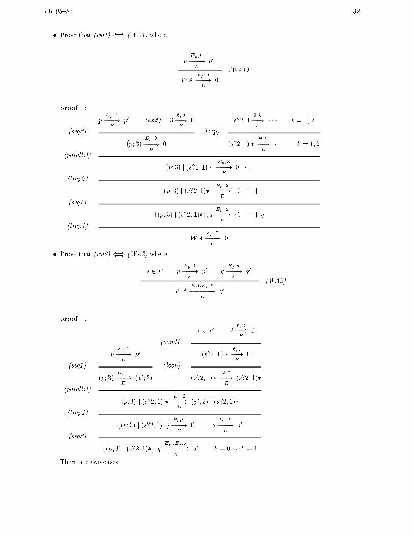
� Prove that (wa1) () (WA1) where
pEp;0���!
Ep0
WAEp;0���!
E0
(WA1)
proof :
pEp;0���!
Ep0 (exit) 3
;; 3��!E
0 s?2; 1;; k��!E� � � k = 1; 2
(seq2) (loop)
(p; 3)Ep; 3���!
E0 (s?2; 1) �
;; k��!E� � � k = 1; 2
(parallel)
(p; 3) j (s?2; 1) �Ep; 3���!
E0 j � � �
(trap2)
f(p; 3) j (s?2; 1)�gEp; 2���!
Ef0 j � � �g
(seq1)
f(p; 3) j (s?2; 1)�g; qEp; 2���!
Ef0 j � � �g; q
(trap1)
WAEp; 0���!
E0
� Prove that (wa2) () (WA2) where
s 2 E pEp;1���!
Ep0 q
Eq; k
���!E
q0
WAEp[Eq; k
������!E
q0(WA2)
proof :
s 2 E 2;; 2��!E
0
(cond1)
pEp; 1���!
Ep0 (s?2; 1) �
;;2��!E
0
(seq1) (loop)
(p; 3)Ep; 1���!
E(p0; 3) (s?2; 1) �
;; 2��!E
(s?2; 1)�
(parallel)
(p; 3) j (s?2; 1) �Ep; 2���!
E(p0; 3) j (s?2; 1)�
(trap1)
f(p; 3) j (s?2; 1)�gEp;0���!
E0 q
Eq ; k
���!E
q0
(seq2)
f(p; 3) j (s?2; 1)�g; qEp[Eq ; k
������!E
q0 k = 0 or k = 1
There are two cases:

TR 95{52 33
{ k = 0: by trap1 the last transition is rewritten as WAEp[Eq ;0
������!E
0
{ k = 1: by trap2 the last transition is rewritten as WAEp[Eq; 1������!
Efq0g. Now, fq0g behaves like q0,
hence WAEp[Eq; 1������!
Eq0
� Prove that (wa3) () (WA3) where
s 62 E pEp;1���!
Ep0
WAEp;ff����!
EWA[p p0]
(WA3)
proof :
s 2 E 1;; 1��!E
0
(cond2)
pEp; 1���!
Ep0 (s?2; 1) �
;;1��!E
0
(seq1) (loop)
(p; 3)Ep; 1���!
E(p0; 3) (s?2; 1) �
;; 1��!E
(s?2; 1)�
(parallel)
(p; 3) j (s?2; 1) �Ep; 1���!
E(p0; 3) j (s?2; 1)�
(trap2)
f(p; 3) j (s?2; 1)�gEp;1���!
Ef(p0; 3) j (s?2; 1)�g
(seq1)
f(p; 3) j (s?2; 1)�g; qEp[Eq; 1������!
Ef(p0; 3) j (s?2; 1)�g; q
(trap2)
WAEp; 1���!
EWA[p p0]
Now, we propose systematic translations of SyncCharts'components into Esterel's programs.
6.2 Star module
Table 5: Star module
module STAR S:% let p be the body of S% let a = InhibitS% assume S be a n-starinput IS; % see Section.4.2.5
output OS; % see Section.4.2.5
trap T in
signal �; �; ! in
continued on next page

TR 95{52 34
continued from previous page
emit �;suspend
suspend
run MACRO p;emit !
when <g0>when immediate �kawait
case <g1> do <e1>...
case <gn> do <en>end await;
exit T
end signal
end trap
end module
% where <g0> = immediate [atrig] (if amod = immediate)
% [atrig] (otherwise)
Comments: In this translation priority is ensured by the await ...case ... statement: cases are writtenin a decreasing order of priority. The immediate or delayed modi�er could have been directly expressed bythe keyword immediate ofEsterel, so that the local signal � would have been useless. Flattening of triggershas been prefered, instead. Non terminal terms are given below:
<opk > <gk> <ek>
m �k �k; �k> �0 � �k �k; �km> �k �; �k; �k� �0 � �k �; �k; �k� ! �k; �k
0-stars have a simpler behavior (no way to leave), this makes it easier to translate.
Table 6: 0-star module
module STAR S:% assume S be a 0-star
% let p be the body of S% let a = InhibitSinput IS; % see Section.4.2.5
output OS; % see Section.4.2.5
suspend
run MACRO p;halt
when <g0>end module
continued on next page
TR 95{52 35
continued from previous page
% where <g0> = immediate [atrig] (if amod = immediate)
% [atrig] (otherwise)
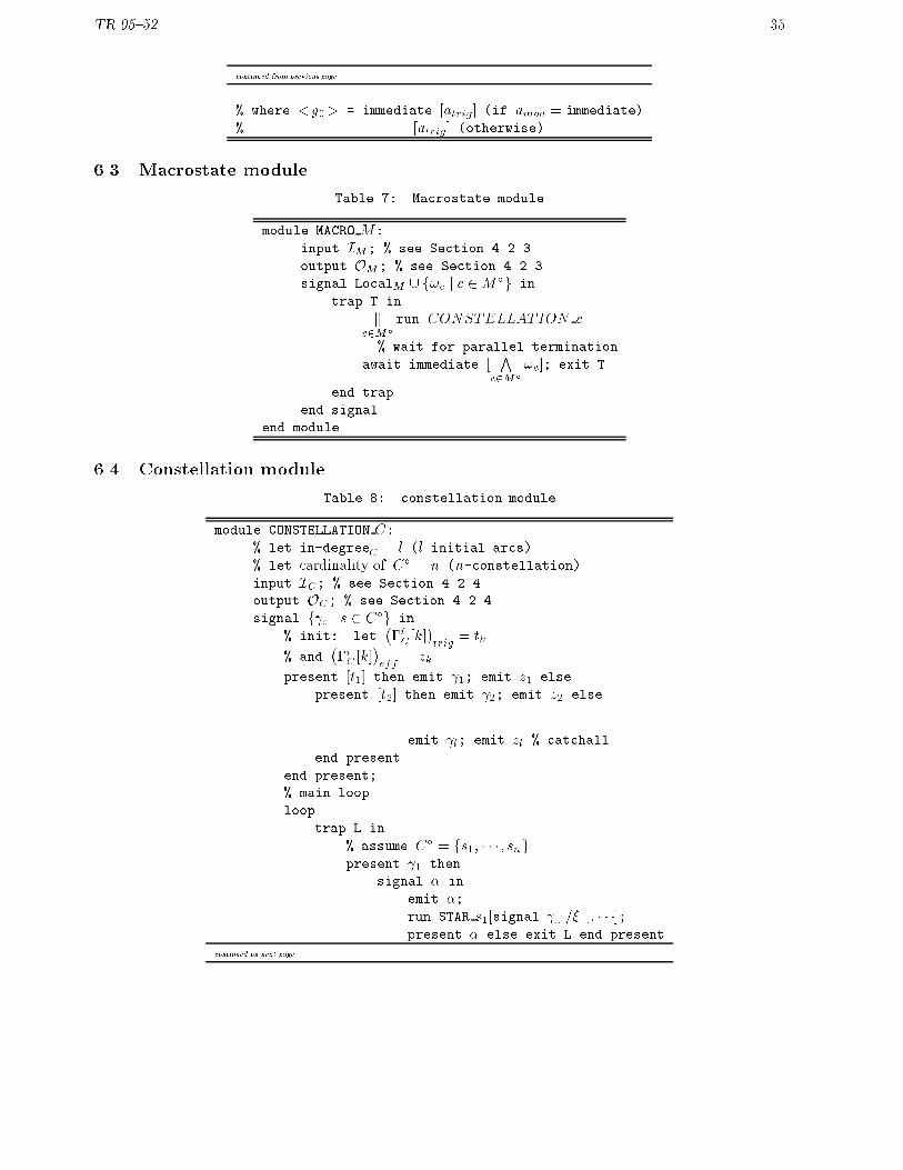
6.3 Macrostate module
Table 7: Macrostate module
module MACRO M:
input IM; % see Section.4.2.3
output OM; % see Section.4.2.3
signal LocalM [ f!c j c 2M�g in
trap T in
kc2M�
run CONSTELLATION c
k % wait for parallel termination
await immediate [V
c2M�
!c]; exit T
end trap
end signal
end module
6.4 Constellation module
Table 8: constellation module
module CONSTELLATION C:% let in-degreeC = l (l initial arcs)
% let cardinality of C� = n (n-constellation)input IC; % see Section.4.2.4
output OC; % see Section.4.2.4
signal f c j s 2 C�g in
% init: let��iC[k]
�trig
= tk
% and��iC [k]
�eff
= zkpresent [t1] then emit 1; emit z1 else
present [t2] then emit 2; emit z2 else
...
emit l; emit zl % catchall
end present
end present;
% main loop
loop
trap L in
% assume C� = fs1; � � � ; sngpresent 1 then
signal � in
emit �;run STAR s1[signal :::=�:::; � � �];present � else exit L end present
continued on next page

TR 95{52 36
continued from previous page
end signal
end present;
% assume s2 2 �fCpresent 2 then
signal �; ! in
emit �;[
do sustain !C watching immediate !krun STAR s2[signal :::=�:::; � � �]; emit !
];
present � else exit L end present
end signal
end present;...
present n then
signal � in
emit �;run STAR sn[signal :::=�:::; � � �];present � else exit L end present
end signal
end present;
halt % horrible trick to fake the compiler
end trap
end loop
end signal
end module
Comments: Signals k stand for goto stark. When entering the constellation, we emit k according tothe satisfaction of the associated triggering events of the initial arcs. At least one is emitted (default initialstar). We then enter the main loop. The idea is to test the presence of the k in the topological order. Ifpresent, the corresponding star is executed.
Suppose we execute stark. If it terminates instantly, then � is still present and the control passes to thenext test (management of transient stars). Otherwise, the trap L is exited and we test again from the verybeginning (management of transitions between steady states).
Terminal stars need a special handling: while the star is running, the signal !C is sustained.Note that the halt statement at the end of the body of the loop should be never executed. We introduced
it for technical reason (the compiler cannot understand that the body of the loop is never 0-duration long).Since a star emits an exit signal (�) when leaving, this signal has to be renamed as a signal according
to the structure of the constellation. This renaming is done by the run statement.
A A Summary of the Esterel Calculus
(Excerpt from G. Berry's paper on Preemption in Concurrent Systems.

TR 95{52 37
A.1 Set of primitives
n for n � 0 (termination code)s for s 62 I (emission)p; q (sequence)p� (loop)s?p; q (conditional)p j q (parallel)p n s for s 2 L (restriction)fpg (trap)" p (shift)s�� p (immediate suspension)
A.2 Rules
n;; n��!E
0 (termination code)
sfsg;0���!
E0 (emission)
pEp ; k
���!E
p0 k 6= 0
p; qEp; k
���!E
p0; q
(seq1)
pEp;0���!
Ep0 q
Eq; k
���!E
q0
p; qEp[Eq ; k
������!E
q0(seq2)
pEp ; k
���!E
p0 k 6= 0
p �Ep; k
���!E
p0; (p�)
(loop)
pEp; kp����!
Ep0 q
Eq; kq����!
Eq0
p j qEp[Eq; max(kp;kq)
������������!E
p0 j q0(parallel)
s 2 E pEp; kp����!
Ep0
s?p; qEp; kp����!
Ep0
(cond1)
s 62 E qEq; kq����!
Eq0
s?p; qEq; kq����!
Eq0
(cond2)
pEp; k
����!E[fsg
p0 s 2 Ep
p n sEp�fsg; k
������!E
p0 n s
(restr1)

TR 95{52 38
pEp; k
����!E�fsg
p0 s 62 Ep
p n sEp; k
���!E
p0 n s
(restr2)
s 2 E
s�� p;; 1��!E
s�� p
(imm. susp1)
s 62 E pEp;0���!
Ep0
s�� pEp; 0���!
E0
(imm. susp2)
s 62 E pEp; k
���!E
p0 k 6= 0
s�� pEp; k
���!E
s�� p0(imm.3)
pEp ; k
���!E
p0 k = 0 or k = 2
fpgEp; 0���!
E0
(trap1)
pEp ; k
���!E
p0 k = 1 or k > 2
fpgEp; #k
����!E
fp0g
(trap2)
pEp; k
���!E
p0
" pEp;"k
����!E
" p0(shift)
# k =
�1 if k = 1k � 1 if k > 2
" k =
8<:0 if k = 01 if k = 1k + 1 if k � 2
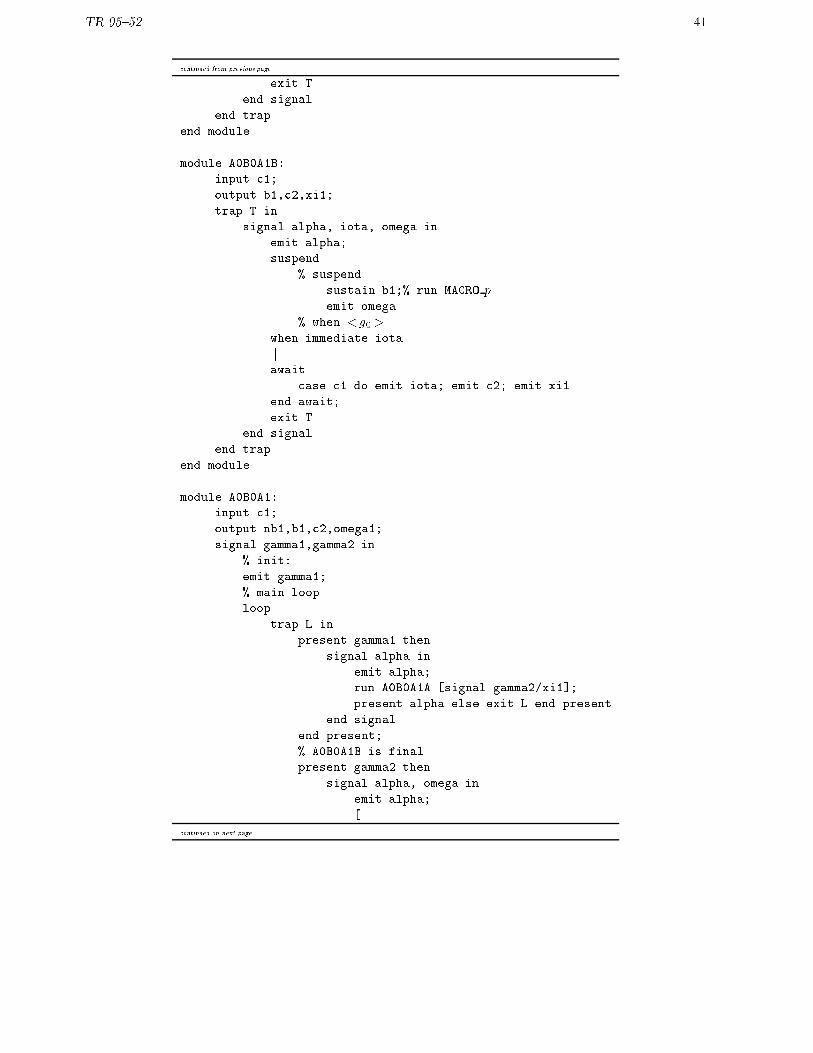
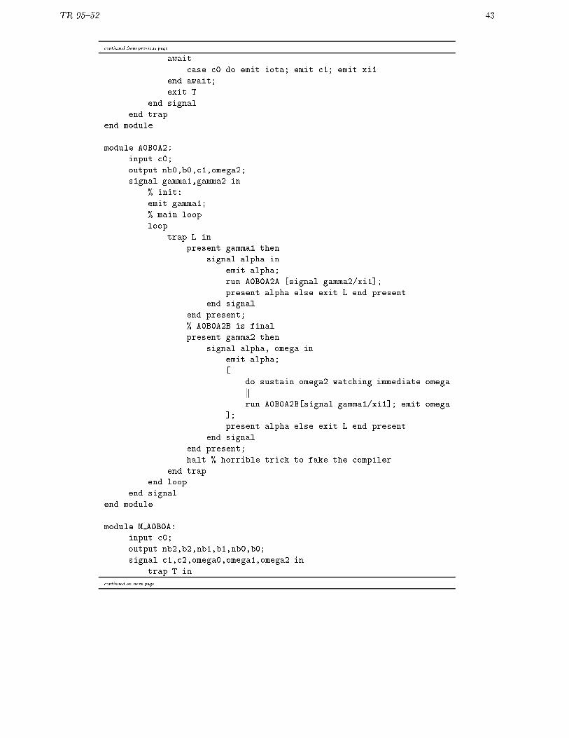
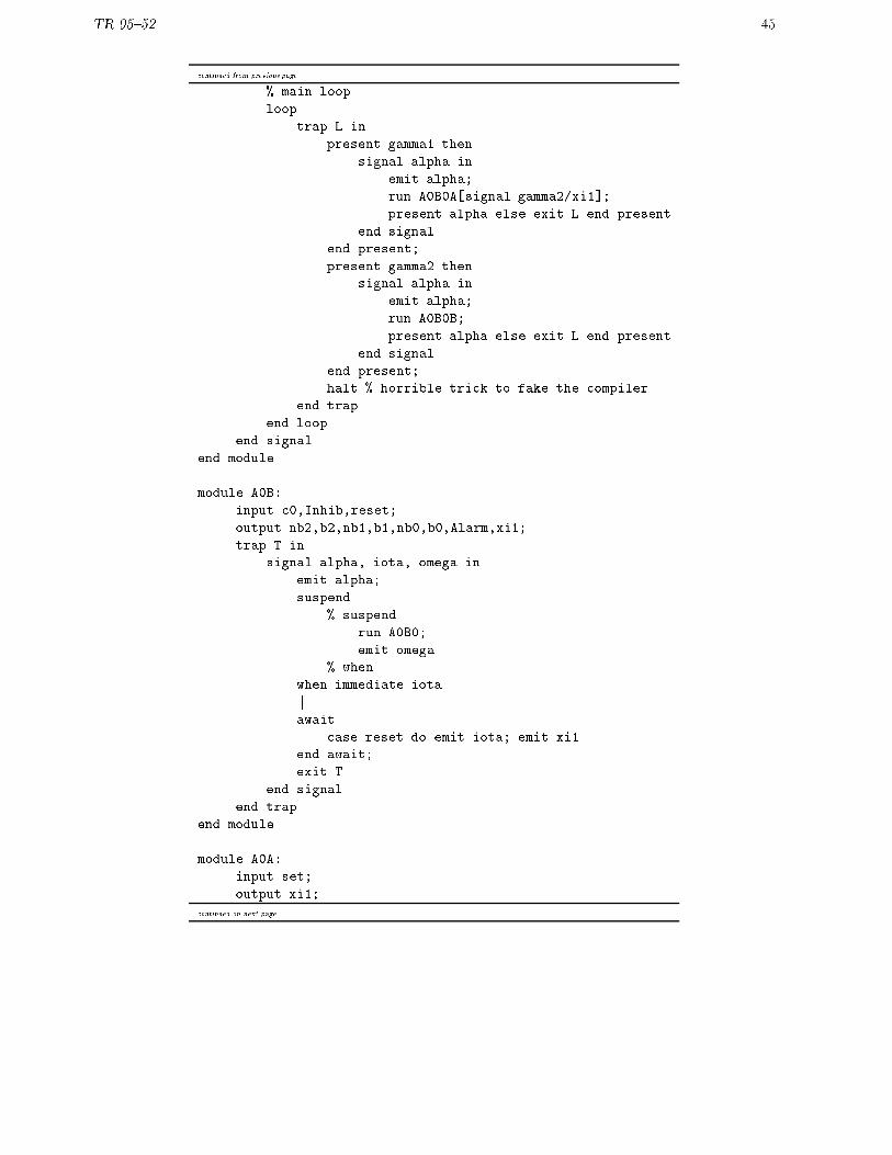
B Esterel translation of the Watchdog SyncCharts
This program has to be compiled with the -oldcausality option. The compiler detects static instantaneousloops which are not e�ective.
Table 9: Translation of Watchdog

TR 95{52 39
% Charles ANDRE
% february 21, 1996
% compilation of the SyncCharts : Watchdog
module A0B0A0A:
input c2;
output nb2,xi1;
trap T in
signal alpha, iota, omega in
emit alpha;
suspend
% suspend
sustain nb2;% run MACRO pemit omega
% when < g0>when immediate iota
kawait
case c2 do emit iota; emit xi1
end await;
exit T
end signal
end trap
end module
module A0B0A0B:
input c2;
output b2,xi1;
trap T in
signal alpha, iota, omega in
emit alpha;
suspend
% suspend
sustain b2;% run MACRO pemit omega
% when < g0>when immediate iota
kawait
case c2 do emit iota; emit xi1
end await;
exit T
end signal
end trap
end module
module A0B0A0:
input c2;
output nb2,b2,omega0;
continued on next page

TR 95{52 40
continued from previous page
signal gamma1,gamma2 in
% init:
emit gamma1;
% main loop
loop
trap L in
present gamma1 then
signal alpha in
emit alpha;
run A0B0A0A [signal gamma2/xi1];
present alpha else exit L end present
end signal
end present;
% A0B0A0B is final
present gamma2 then
signal alpha, omega in
emit alpha;
[
do sustain omega0 watching immediate omega
krun A0B0A0B[signal gamma1/xi1]; emit omega
];
present alpha else exit L end present
end signal
end present;
halt % horrible trick to fake the compiler
end trap
end loop
end signal
end module
module A0B0A1A:
input c1;
output nb1,xi1;
trap T in
signal alpha, iota, omega in
emit alpha;
suspend
% suspend
sustain nb1;% run MACRO pemit omega
% when <g0>when immediate iota
kawait
case c1 do emit iota; emit xi1
end await;
continued on next page
TR 95{52 41
continued from previous page
exit T
end signal
end trap
end module
module A0B0A1B:
input c1;
output b1,c2,xi1;
trap T in
signal alpha, iota, omega in
emit alpha;
suspend
% suspend
sustain b1;% run MACRO pemit omega
% when <g0>when immediate iota
kawait
case c1 do emit iota; emit c2; emit xi1
end await;
exit T
end signal
end trap
end module
module A0B0A1:
input c1;
output nb1,b1,c2,omega1;
signal gamma1,gamma2 in
% init:
emit gamma1;
% main loop
loop
trap L in
present gamma1 then
signal alpha in
emit alpha;
run A0B0A1A [signal gamma2/xi1];
present alpha else exit L end present
end signal
end present;
% A0B0A1B is final
present gamma2 then
signal alpha, omega in
emit alpha;
[
continued on next page

TR 95{52 42
continued from previous page
do sustain omega1 watching immediate omega
krun A0B0A0B[signal gamma1/xi1]; emit omega
];
present alpha else exit L end present
end signal
end present;
halt % horrible trick to fake the compiler
end trap
end loop
end signal
end module
module A0B0A2A:
input c0;
output nb0,xi1;
trap T in
signal alpha, iota, omega in
emit alpha;
suspend
% suspend
sustain nb0;% run MACRO pemit omega
% when <g0>when immediate iota
kawait
case c0 do emit iota; emit xi1
end await;
exit T
end signal
end trap
end module
module A0B0A2B:
input c0;
output b0,c1,xi1;
trap T in
signal alpha, iota, omega in
emit alpha;
suspend
% suspend
sustain b0;% run MACRO pemit omega
% when <g0>when immediate iota
kcontinued on next page
TR 95{52 43
continued from previous page
await
case c0 do emit iota; emit c1; emit xi1
end await;
exit T
end signal
end trap
end module
module A0B0A2:
input c0;
output nb0,b0,c1,omega2;
signal gamma1,gamma2 in
% init:
emit gamma1;
% main loop
loop
trap L in
present gamma1 then
signal alpha in
emit alpha;
run A0B0A2A [signal gamma2/xi1];
present alpha else exit L end present
end signal
end present;
% A0B0A2B is final
present gamma2 then
signal alpha, omega in
emit alpha;
[
do sustain omega2 watching immediate omega
krun A0B0A2B[signal gamma1/xi1]; emit omega
];
present alpha else exit L end present
end signal
end present;
halt % horrible trick to fake the compiler
end trap
end loop
end signal
end module
module M A0B0A:
input c0;
output nb2,b2,nb1,b1,nb0,b0;
signal c1,c2,omega0,omega1,omega2 in
trap T in
continued on next page

TR 95{52 44
continued from previous page
run A0B0A0
krun A0B0A1
krun A0B0A2
k% wait for parallel termination
await immediate [omega0 and omega1 and omega2]; exit T
end trap
end signal
end module
module A0B0A:
input c0,Inhib;
output nb2,b2,nb1,b1,nb0,b0,xi1;
trap T in
signal alpha, iota, omega in
emit alpha;
suspend
suspend
run M A0B0A;
emit omega
when Inhib
when immediate iota
kawait
case immediate omega do emit xi1
end await;
exit T
end signal
end trap
end module
module A0B0B:
% input ;
output Alarm;
% suspend
sustain Alarm
% when
end module
module A0B0:
input c0,Inhib;
output nb2,b2,nb1,b1,nb0,b0,Alarm;
signal gamma1,gamma2 in
% init:
emit gamma1;
continued on next page
TR 95{52 45
continued from previous page
% main loop
loop
trap L in
present gamma1 then
signal alpha in
emit alpha;
run A0B0A[signal gamma2/xi1];
present alpha else exit L end present
end signal
end present;
present gamma2 then
signal alpha in
emit alpha;
run A0B0B;
present alpha else exit L end present
end signal
end present;
halt % horrible trick to fake the compiler
end trap
end loop
end signal
end module
module A0B:
input c0,Inhib,reset;
output nb2,b2,nb1,b1,nb0,b0,Alarm,xi1;
trap T in
signal alpha, iota, omega in
emit alpha;
suspend
% suspend
run A0B0;
emit omega
% when
when immediate iota
kawait
case reset do emit iota; emit xi1
end await;
exit T
end signal
end trap
end module
module A0A:
input set;
output xi1;
continued on next page

TR 95{52 46
continued from previous page
trap T in
signal alpha, iota, omega in
emit alpha;
suspend
% suspend
halt;
emit omega
when immediate iota
kawait
case set do emit iota; emit xi1
end await;
exit T
end signal
end trap
end module
module A0:
input c0,Inhib,reset,set;
output nb2,b2,nb1,b1,nb0,b0,Alarm;
signal gamma1,gamma2 in
% init:
emit gamma1;
% main loop
loop
trap L in
present gamma1 then
signal alpha in
emit alpha;
run A0A[signal gamma2/xi1];
present alpha else exit L end present
end signal
end present;
present gamma2 then
signal alpha in
emit alpha;
run A0B[signal gamma1/xi1];
present alpha else exit L end present
end signal
end present;
halt % horrible trick to fake the compiler
end trap
end loop
end signal
end module
module A:
continued on next page

TR 95{52 47
continued from previous page
input c0,Inhib,reset,set;
output nb0,b0,nb1,b1,nb0,b0,Alarm;
% suspend
run A0
% when
end module
References
[BB91] A. Benveniste and G. Berry. The synchronous approach to reactive and real-time systems. Proceedingof the IEEE, 79(9):1270{1282, September 1991.
[Bee94] M. von der Beeck. A comparison of statecharts variants. In Proc. of Formal Techniques in RealTime and Fault Tolerant Systems, volume 863 of Lecture Notes in Computer Science, pages 128{148.FTRTFT'94, Springer-Verlag, 1994.
[Ber92] G. Berry. Preemption in concurrent systems. Proc FSTTCS, Lecture notes in Computer Science,761:72{93, 1992.
[Har87] D. Harel. Statecharts: A visual formalism for complex systems. Science of computer program-ming, 8:231{274, 1987.
[IEC88] IEC, Gen�eve (CH). Preparation of function charts for control systems, december 1988. Internationalstandard IEC 848.
[Mar90] F. Maraninchi. Argos: un langage graphique pour la conception, la description et la validation dessyst�emes r�eactifs. PhD thesis, Universit�e Joseph Fourier, Grenoble I, Janvier 1990.
[Rei85] W. Reisig. Petri nets: an introduction. Monograph on Theoretical Computer Science. Springer-Verlag, Berlin, 1985.