tracking systems - tum
TRANSCRIPT
Tracking Systems
Kevin Cleary, PhD
Technical Director, Bioengineering Initiative
Children's National Medical Center
Adjunct Professor, Department of Radiology
Georgetown University Medical Center
Washington, DC, USA
MICCAI 2011 Toronto

CAIMR Lab Georgetown UniversitySlide 2
Tracking Systems
• Track (locate) objects in space
– 3 degrees of freedom for position
– 3 degrees of freedom for orientation
– 6 degrees of freedom for a rigid body
– Most can track multiple objects
• Tracker types
– Mechanical (early systems)
– Optical (standard of care)
– Electromagnetic (hot topic)

CAIMR Lab Georgetown UniversitySlide 3
Localizer Slides Courtesy of Robert Galloway, PhD, Vanderbilt University,
Technology Guided Therapy Program
Early Mechanical Localizers:
Mark I and Mark II Articulated Arms

CAIMR Lab Georgetown UniversitySlide 4
Pros and Cons of
Articulated Arms
• Pros
– Highly reliable
– Highly accurate
– Highly stable
• Cons
– Cumbersome to use
– Can easily interfere with surgical field
– Cannot track multiple devices

CAIMR Lab Georgetown UniversitySlide 5
Optical Localizers:
Principle of Triangulation

CAIMR Lab Georgetown UniversitySlide 6
Optical Localizer Classification
• Infrared-based (IR) tracking systems
– Active optical systems
• Optotrak Certus (Northern Digital Inc.)
– Passive / active optical systems
• Polaris Spectra and Vicra (Northern Digital Inc.)
• Videometric tracking systems
– Micron Tracker (Claron Technology)
• Laser tracking systems
– laserBird2 (Ascension Technology)

CAIMR Lab Georgetown UniversitySlide 7
Infrared-based:
Optotrak Certus• Three-camera system
• Accuracy: very high
– 0.15 mm maximum
• Field of view: large
– Greater than 1 cubic meter
• Physical size: large
– 1126 mm x 200 mm x 161 mm
• Tool tracking: active sensors
Specifications from: http://www.ndigital.com/research/certus.php
Figure courtesy of Northern Digital Inc.

CAIMR Lab Georgetown UniversitySlide 8
Multiface Tool
• > 60 degree visibility
• Requires high speed location of sources.
CAIMR Lab Georgetown UniversitySlide 9
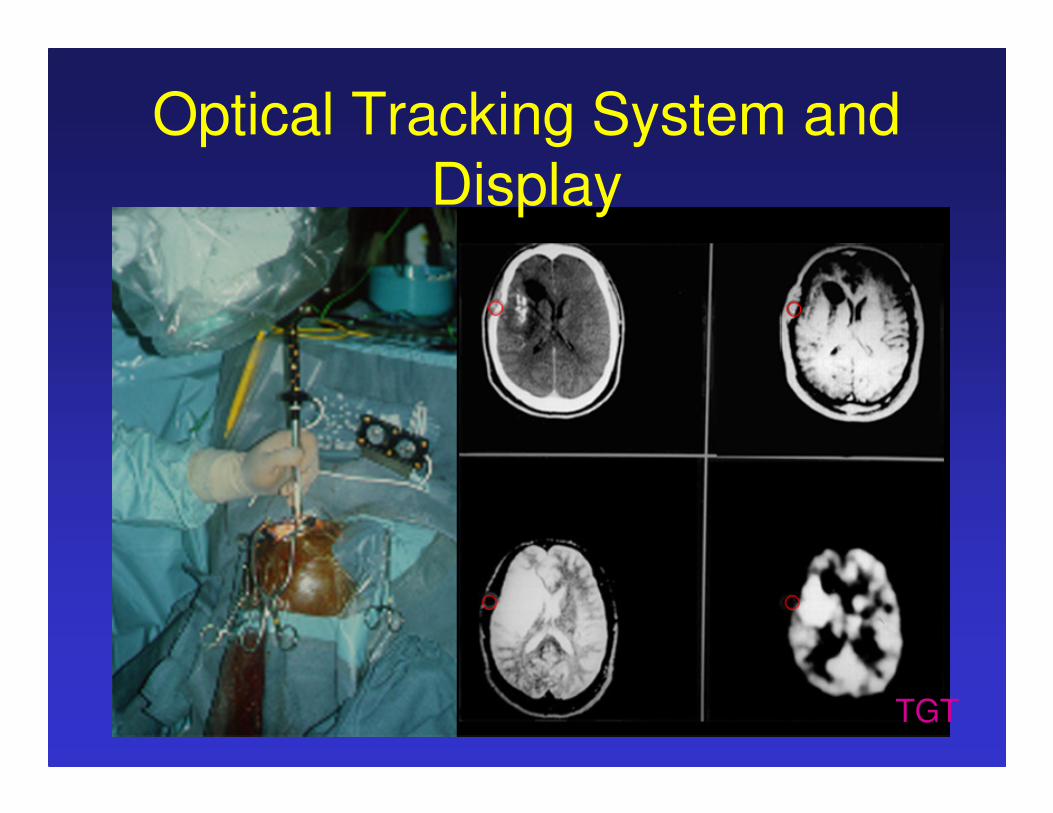
Optical Tracking System and
Display
TGT
CAIMR Lab Georgetown UniversitySlide 10
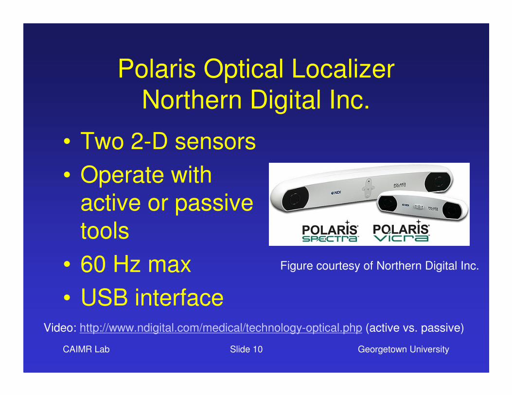
Polaris Optical Localizer
Northern Digital Inc.
• Two 2-D sensors
• Operate with
active or passive
tools
• 60 Hz max
• USB interface
Figure courtesy of Northern Digital Inc.
Video: http://www.ndigital.com/medical/technology-optical.php (active vs. passive)

CAIMR Lab Georgetown UniversitySlide 11
Working Volume (Field of View)
Figures courtesy of Northern Digital Inc.
Polaris Spectra Polaris Vicra

CAIMR Lab Georgetown UniversitySlide 12
Active Tools
Description from Northern Digital Inc.
• Infrared-emitting markers that are activated by an electrical current
• Tool geometries can be small since the same geometry can be used multiple times
• Markers can be cleaned easily
• Tool description file can be programmed into tool

CAIMR Lab Georgetown UniversitySlide 13
Passive Tools
Northern Digital Inc.
• Spherical, retro-reflective markers
that reflect infrared light emitted by
the illuminators on the position
sensor
• Wireless
• Track numerous tools without
reducing sample rate
• Need unique geometry for each
tool – tools can be large

CAIMR Lab Georgetown UniversitySlide 14
Choosing an Optical Tracking System(courtesy Northern Digital)
• Size of measurement volume needed
• Update rate required for tracking
• Number of tools to be tracked
• Space restrictions and mounting location of system
• Integration/compatability with current Polaris system

CAIMR Lab Georgetown UniversitySlide 15
Setting Up Your Tracker
(practical advice)
• Hardware– Need something to mount the tracker on
• Tripod is a good solution
• Buy a good one
– Need some way to attach the tools to the object to be tracked
• Can bolt directly or use clamp from Northern Digital
• Software
– Trackers now come with a USB interface
– They also have an application programming interface• More on this later
CAIMR Lab Georgetown UniversitySlide 16
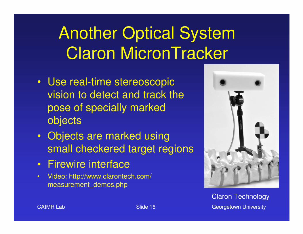
Another Optical System
Claron MicronTracker
• Use real-time stereoscopic
vision to detect and track the
pose of specially marked
objects
• Objects are marked using
small checkered target regions
• Firewire interface• Video: http://www.clarontech.com/
measurement_demos.php
Claron Technology

CAIMR Lab Georgetown UniversitySlide 17
Electromagnetic versus
Optical Tracking
• Tracking for image-guided surgery has been dominated by optical trackers– Advantages
• Relatively large field of view• Highly accurate
– Disadvantages• Require maintaining a line of sight• Therefore cannot track instruments inside the body
• Electromagnetic tracking– Does not require a line of sight
– Therefore can track inside the body

Courtesy of Northern Digital Inc.
Electromagnetic Tracking
Principle of Operation

CAIMR Lab Georgetown UniversitySlide 19
Footnote for Panel Discussion
• The term “electromagnetic” tracking has historically been used to describe systems that are based on
magnetic fields
• Some researchers may argue that these systems
should be called “magnetic” spatial measurement
systems since they do not depend on the electric field component of the electromagnetic wave
• However, we will use the term electromagnetic here to reflect common usage and the fact that a varying
magnetic field has an associated electric component

CAIMR Lab Georgetown UniversitySlide 20
Electromagnetic Tracker
Characterization
• AC driven systems
– FASTRAK (Polhemus Inc.)
– Aurora (Northern Digital Inc.)
• DC driven systems
– 3D Guidance (Ascension Technology)
• Passive or transponder systems
– Calypso 4D system (Calypso Inc.)

CAIMR Lab Georgetown UniversitySlide 21
Polhemus AC Driven Tracking
• From their website– Polhemus pioneered AC
motion tracking
– Unlike products based on pulsed DC technology, Polhemus trackers are not negatively affected by the earth's magnetic field, power outlets or electric motors
• Not currently used in image-guided systems though since
small tools are not available
Figure courtesy of Polhemus Inc.

CAIMR Lab Georgetown UniversitySlide 22
Aurora
• Enables non-line of sight tracking
• Tracks up to 8 tools using miniature sensor coils
• Maximum rate of 40 Hz
• Measurement volume
– 500 mm cubed
– Starting 50 mm from field generator
Figures courtesy of Northern Digital

CAIMR Lab Georgetown UniversitySlide 23
MagTrax Needle, Traxtal IncCourtesy of Northern Digital Inc.
Electromangetically Tracked
Biopsy Needles

CAIMR Lab Georgetown UniversitySlide 24
Current Work

Vertebroplasty
EM Navigation system
Aurora

CAIMR Lab Georgetown UniversitySlide 26
3D Guidance (Ascension)
• Track up to eight miniaturized 6 DOF sensors
or twenty-four 5 DOF
sensors simultaneously
• Driven by quasistatic direct
current (DC)
– Can be more immune to eddy current distortions caused by common conductive metals, such as stainless steel (300 series), titanium, and aluminium
Figures courtesy of Ascension

CAIMR Lab Georgetown UniversitySlide 27
“Metal Immune” Flat Transmitter
• Placed beneath a patient to negate any possible
distortion of measurements
by ferrous metal in an OR or procedural table
• ±20 cm X, Y, 10--46 cm Z coverage
• Radio-translucent and radio-opaque models available Figures courtesy of Ascension

Flock of birds
field generator
tracked coil

CAIMR Lab Georgetown UniversitySlide 29
Calypso System for Prostate
External Beam Radiation
• System components
– 1) Beacon electromagnetic transponder (implanted in patient)
– 2) 4D console (in room monitoring for setup)
– 3) 4D electromagnetic array
– 4) 4D tracking system (out of room monitoring)
– 5) Optical system (for initial positioning)
Figures courtesy of Calypso Medical

IGSTK Open Source Software
(image-guided surgical toolkit: igstk.org)

CAIMR Lab Georgetown UniversitySlide 31
How to Choose a Tracker
• Must be based on clinical application
• First, do you need to track inside the body?– Choice of electromagnetic versus optical
• Second, what is the tracking volume required?
• Third what are the tools required?
• Good topic for panel discussion

CAIMR Lab Georgetown UniversitySlide 32
• Clinicians– Filip Banovac, MD– Vance Watson, MD– Elliot Levy, MD
• Scientists / Researchers– David Lindisch, RT– Patrick Cheng, MS– Ziv Yaniv, PhD– Emmanuel Wilson, MS– Seong K. Mun, PhD
• Collaborators– Brad Wood, MD, NIH Radiology
Acknowledgments