trailer anti-lock braking system approval …inform.wabco-auto.com/intl/pdf/600/eb123_8e.pdf ·...
TRANSCRIPT

eb123_8e.doc
Mobi l i tä t
TÜV NORD Mobi l i tät GmbH & Co. KG
IFM – Institute for Vehicle Technology and Mobility
Adlerstraße 7
45307 Essen
Tel.: +49 (0)201 825-4120
Fax: +49 (0)201 825-4150
www.tuev-nord.de
Corporate seat: Hannover
Commercial Register section
HRA 27006
Management:
Volker Drube
TRAILER ANTI-LOCK BRAKING
SYSTEM APPROVAL REPORT
A p p r o v a l R e p o r t N o : E B 1 2 3 . 8 E
0. General
The purpose of this report is to add the variant E to the Trailer EBS (in addition to the variant D).
For the sake of clarity the two different variants are covered by separate reports.
Variant D is covered by the TÜV NORD System Approval Report EB123.7E and variant E by this report.
Thus, all tests which are related to the variant D are eliminated in this report.
For the sake of simplicity the Manufacturer’s Information Docu-ment “ID_EB123.8E” of the Trailer EBS E system is abbreviated to I D _ T E B S .
1. Identification
1.1 Manufacturer: WABCO Vehicle Control Systems
Am Lindener Hafen 21
D - 30453 Hannover
1.2 System name/model: Trailer EBS
1.3 System variant: E (see also paragraph 1.3 of ID_TEBS)
Versions: - Trailer EBS E
- Trailer EBS E with TCE*
* TCE: Trai le r Centra l Electronic
Note: Regarding the description of the above mentioned different versions see paragraph 2.1.3 of ID_TEBS.

A p p r o v a l R e p o r t N o . E B 1 2 3 . 8 E
Manufacturer: WABCO
ABS-System: Trailer EBS (E) page 2 / 9
eb123_8e.doc
2. System and installation
2.1 Configurations: 2S/2M - 2S/2M+SLV - 4S/2M - 4S/2M+1M - 4S/3M
See also paragraph 2.1 and Appendix 1 of ID_TEBS
2.1.1 Category A performance: All anti-lock system configurations and installations de-fined in Appendix 1 of ID_TEBS comply with the pre-scribed split friction requirements defined in paragraph 6.3.2 of annex X to Directive 71/320/EEC and annex 13 to ECE-Regulation No. 13.
2.2. Range of application: All system configurations as defined in 2.1 above may be used on semi- or centre-axle trailers having up to 3 axles.
4S/3M configurations may be used on full trailers with ei-ther 2 or 3 axles.
For specific applications refer to section 2 and Appendix 1 of ID_TEBS.
For more detailed system installation examples refer to paragraph 3.5 and Appendix 4 of ID_TEBS.
2.3 Methods of powering: All system configurations have the ability to accept a con-tinuous power supply via the prescribed special connector conforming to ISO 7638 and - as a back up - an intermit-tent power supply via the ISO 1185 (24N) or ISO 12098 connector (stop lamp circuit).
Permanent To comply with the requirements of Directive 71/320/EEC and ECE Regulation 13 full functionality of the system can only be obtained when connected to an interface con-forming to the following standards:
ISO 7638:1985 5 Pin
ISO 7638:1997 Part 1 (24 V) 5 Pin
ISO 7638:1997 Part 1 (24 V) 7 Pin
Intermittent: As a safety function in the event of a failure of the perma-nent ISO 7638 electrical power supply the system is able to receive intermittently electrical power from the ISO 1185 (24N) or ISO 12098 connector (stop lamp cir-cuit). In this case only the anti-lock braking and the load-dependent brake force controls are available.
For more detailed information see ID_TEBS, paragraphs 1.5 and 3.4.

A p p r o v a l R e p o r t N o . E B 1 2 3 . 8 E
Manufacturer: WABCO
ABS-System: Trailer EBS (E) page 3 / 9
eb123_8e.doc
2.4 Identification of approved components
2.4.1 Wheel speed sensors: see paragraph 3.1 of ID_TEBS 2.4.2 Controller: see paragraph 3.2 of ID_TEBS
2.4.3 Modulators: see paragraph 3.3 of ID_TEBS
The part numbers not fully specified in ID_TEBS indicate that deviations from the listed equipment/components are possible. These, however, have no influence on the func-tions and effect with regard to the inspection performed.
2.5 Energy consumption
2.5.1 Drum brakes
2.5.1.1 Equivalent static brake applications:
Semi-trailers: ne_EC = 11 applications
ne_ECE = 13 applications
Full trailers: ne_EC = 11 applications
ne_ECE = 13 applications
Notes :
• The values ne_EC above is to be used with the verification
procedure defined within annex XIV, paragraph 6.2 of Di-
rective 71/320/EEC.
• The values ne_ECE above is to be used with the verification
procedure defined within annex 20, paragraph 7.3 of ECE-
Regulation No. 13.
2.5.1.2 Ratio of actuator stroke against brake lever length: R = sT / lT = 0.2 (in all cases)
2.5.2 Disc brakes: Annex XIV of Directive 71/320/EEC only defines a test procedure for trailers with drum brakes but states that al-ternative designs may be taken into consideration. In the case of disc brakes it is not possible to manipulate the stroke/pressure relationship due to the integration of auto-matic wear adjustment. To establish an alternative proce-dure, comparative testing was carried out with an unmodi-fied installation and an installation with a 20 % increase in

A p p r o v a l R e p o r t N o . E B 1 2 3 . 8 E
Manufacturer: WABCO
ABS-System: Trailer EBS (E) page 4 / 9
eb123_8e.doc
delivery volume. This simulated a condition of R x 1,2 so that the equivalent number of static brake applications could be defined for the increased volume condition. This value is defined below as ne_EC.
2.5.2.1 Equivalent static brake applications: see also ID_TEBS, paragraph 2.6.1.3
Semi-trailers: ne_EC = 11 applications
ne_ECE = 12 applications
Full trailers: ne_EC = 11 applications
ne_ECE = 12 applications
Notes:
-• The brake applications ne_EC defined above already take
account of an increase in delivery volume of 20 %. There-
fore, only in the case of trailers equipped with disc brakes,
the procedure defined in paragraph 6.2.1.2 of annex XIV of
Directive 71/320/EEC is to be carried out without any in-
crease in actuator stroke as defined in paragraph 6.2.1.1 of
annex XIV.
• The values ne_ECE above is to be used with the verification
procedure defined within annex 20, paragraph 7.3 of ECE-
Regulation No. 13.
2.6 Additional features: The following additional features are provided as options. They are not subject to the assessment of this re-port.
2.6.1 Load-dependent brake force control (LSV): see ID_TEBS, paragraph 1.5.1.1.2
2.6.2 Monitoring of brake air pressure: see ID_TEBS, paragraph 1.5.1.1.7
2.6.3 Lifting axle control: see ID_TEBS, paragraph 1.5.1.1.8
2.6.4 Integrated speed switch: see ID_TEBS, paragraph 1.5.1.1.9
2.6.5 Standstill function: see ID_TEBS, paragraph 1.5.1.1.5
2.6.6 Emergency braking function: see ID_TEBS, paragraph 1.5.1.1.6
2.6.7 Roll Stability Support : see ID_TEBS, paragraph 1.5.1.1.11
2.6.8 ECAS: see ID_TEBS, paragraph 1.5.1.1.12
2.6.9 Parameter setting: see ID_TEBS, paragraph 1.5.1.1.13

A p p r o v a l R e p o r t N o . E B 1 2 3 . 8 E
Manufacturer: WABCO
ABS-System: Trailer EBS (E) page 5 / 9
eb123_8e.doc
3. Test data and results
3.0 General: (e.g. test schedule, worst case cross referencing) see Ap-pendix 4 of this approval report
This System Approval Report covers only the Trailer EBS “E”variant.
All tests for the Trailer EBS “D” variant which have been carried out are described in the System Approval Re-port EB123.7E of TÜV NORD.
To differentiate between the various tests for the variants D and E (new modulator design) the following distin-guishing symbol is used:
“.8” Tests carried out for this System Approval Report EB123.8E of TÜV NORD
3.1. Test vehicle data: see Appendix 3 of this approval report
3.2. Test surface information: see Appendix 2 of this approval report
3.3. Test results
3.3.1. Utilisation of adhesion: see Appendix 4-1 of this approval report
3.3.2. Energy consumption
3.3.2.1 Worst case axle load: see paragraph 2.7 of ID_TEBS.
3.3.2.2 Test results: see Appendix 4-2 of this approval report
3.3.3. Split-friction test: see Appendix 4-3 of this approval report
3.3.4. Low speed performance: see Appendix 4-4, paragraph 1 of this approval report
3.3.5. High speed performance: see Appendix 4-4, paragraph 2 of this approval report
3.3.6. Additional checks
3.3.6.1 Transition from high to
low-adhesion surfaces: see Appendix 4-4, paragraph 3 of this approval report
3.3.6.2 Transition from low to
high-adhesion surfaces: see Appendix 4-4, paragraph 4 of this approval report

A p p r o v a l R e p o r t N o . E B 1 2 3 . 8 E
Manufacturer: WABCO
ABS-System: Trailer EBS (E) page 6 / 9
eb123_8e.doc
3.3.7 System safety assessment/ failure mode simulation: The assessment and simulation was carried out following
the procedure defined within Annex 18 to ECE-Regulation No. 13. The results from this assessment are reported in TÜV NORD Test Report EB 124.4E (see Annex 1 “Elec-tronic Function & Safety”).
3.3.8. Functional checks of optional power connections: A failure of the ISO 7638 power supply was simulated by
disconnecting the connector. In this case the anti-lock braking function and load dependent pressure control re-mains operational when the system is wired to the stop lamp supply of either the ISO 1185 or ISO 12098 connec-tions. This mode of operation is intended to enhance the failure modes of the braking system in the event of a fail-ure of the ISO 7638 power supply occurs in service and is not a means of powering the braking system when no power supply failure exists (see also paragraph 2.3 of this report and paragraphs 1.5.1 c) and 3.4 of ID_TEBS).
3.3.9 Electromagnetic compatibility: The system has been tested and verified to conform to the requirements of Directive 72/245/EEC as last amended by Directive 2006/28/EC* . A copy of the approval report is included in ID_TEBS (see paragraph 3.6 and Appendix 6 of that document).
* Note: This approval does not make reference to ECE-Regula-tion 10. However, the performance requirements of Di-rective 72/245/EEC as last amended by Directive 2006/28/EC are more extensive than those of ECE-Regulation 10/02. Since Directive 72/245/EEC contains also all technical requirements of ECE-Regulation 10/02 compliance with ECE-Regulation 10/02 is assured as well.
3.3.10 ADR regulations: Within the test procedure according to Annex XIV and Annex 19 resp. no assessment was performed against ADR (Regulation governing Road Transport of Hazardous Goods). For information, see WABCO statement in the Manufacturer’s Information Document, paragraph 3.4.

A p p r o v a l R e p o r t N o . E B 1 2 3 . 8 E
Manufacturer: WABCO
ABS-System: Trailer EBS (E) page 7 / 9
eb123_8e.doc
4. Limitations of installation
4.1. Tyre to exciter relationship: The relationship of tyre circumference to the resolution of the exciter is defined in ID_TEBS, paragraph 2.3.
4.2. Tyre size tolerance: The permissible tolerance on tyre circumference between one axle and another fitted with the same exciter is defined in ID_TEBS, paragraph 2.4, see also Appendix 5, para-graph 1 to this approval report.
4.3. Suspension type: System performance was verified on trailers with balanced pneumatic and mechanical suspensions. Paragraph 2.5 and Appendix 2 of ID_TEBS defines approved suspensions for the purpose of the application of this approval.
In the case semi-trailers the measured braking perform-ances refer to vehicle combinations where the coupling heights (fifth wheel) of the tractor and trailer where of a similar height, thus leading to equal static loads among the trailer axles (no or almost no longitudinal inclination of the trailer chassis).
4.4. Differential(s) in brake input
torque within a trailer bogie: - permissible on all system configurations
see also paragraph 2.6 of ID_TEBS and Appendix 5, paragraph 2 to this approval report
4.5. Wheel base of full trailer
4.5.1 Two axle full trailers: The wheel base is defined as the distance between centre line of axle 1 and the centre line of axle 2. The minimum approved wheel base being 3000 mm.
4.5.2 Three axle full trailers: The wheel base is defined as the distance between centre line of axle 1 and the centre between the wheels of axles 2 and 3. The minimum approved wheel base being 3745 mm.

A p p r o v a l R e p o r t N o . E B 1 2 3 . 8 E
Manufacturer: WABCO
ABS-System: Trailer EBS (E) page 8 / 9
eb123_8e.doc
4.6. Brake type: The anti-lock system configurations covered by this ap-proval are deemed to be satisfactory for trailers equipped with either air operated drum or disc brakes.
4.7. Tube sizes and lengths: see paragraph 3.5 of ID_TEBS and Appendix 5, para-graph 2 to this approval report
Note: The use of the tube sizes recommended does not guarantee that the prescribed brake system response time can be fulfilled, therefore it shall be demonstrated that this requirement is fulfilled for each installation.
4.8. Load sensing device application: not applicable (LSV function - see paragraph 1.5.1.1.2 of ID_TEBS)
4.9. Warning signal sequence: All configurations have the option of two discrete warning signal sequences - see paragraph 3.4 of ID_TEBS - both of which fulfil the prescribed requirements of Directive 71/320/EEC and ECE-Regulation No. 13.
4.10 Other recommendations/limi- tations
4.10.1 Installation limitations: For approved installation options with respect to sen-sor/modulator locations and recommendations for the use of lifting and steering axles see Appendix 1 of ID_TEBS.
Note: This report does not cover an assessment of the reaction of the available steering systems to the anti-lock braking control of the “Trailer EBS”.
5. Date of test: 1997 - 1999 - 2002 – 2004 - 2006
The tests have been carried out and the results reported in accordance with Annex 19 to ECE Regulation No. 13 as last amended by the 10 series of amendments including Supplement 2 and Annex XIV of Directive 71/320/EEC as last amended by Directive 2002/78/EC.
6 Appendices
Appendix 1 Abbreviations & Codes
Appendix 2 Test track data
Appendix 3 Test vehicle data


Trailer EBS E
p a g e 1 / 2 Append ix 1
eb123_8e.doc
Appendix 1 - Abbreviat ions & Codes
.8 Distinguishing symbols to denote tests carried out with the test vehicles used for the System Approval Report EB123.8E.
A14 Energy consumption tests according to the procedure defined within annex XIV of Directive 71/320/EEC
A19 Energy consumption tests according to the procedure defined within annex 19 of ECE-Regulation No. 13
“ABS” measurement of “z” with the anti-lock braking system in operation
BC brake cylinder
E wheel base
ER distance between king-pin and centre of axle or axles of semi-trailer.
εεεε the adhesion utilised by the vehicle: quotient of the maximum braking rate with the anti-lock braking system operative (z
AL) and the coefficient of adhesion (k)
f f = zRALH / zRALL
hR height of centre of gravity of trailer
hD height of drawbar (hinge point on trailer)
hK height of fifth wheel coupling (king pin)
ID_TEBS Manufacturer’s Information Document of the Trailer EBS E system
INR indirectly control
INSR indirectly sidewise control
IR individual control
k coefficient of adhesion between tyre and road
“K” measurement of “k” with the anti-lock braking system inoperative between 40 km/h and 20 km/h
lT brake lever length in mm
LSV load sensing valve (LSV function: load-dependent brake force control)
MAR modified axle control
MSR modified sidewise control
ne number of equivalent static brake applications
PA mass of the trailer
Pf mass of the front axle of the full trailer
PM mass of the motor vehicle (including imposed king pin load if applicable)

Trailer EBS E
p a g e 2 / 2 Append ix 1
eb123_8e.doc
PMd total normal static reaction of road surface on the unbraked and driven axles of the motor vehicle
PMnd total normal static reaction of road surface on the unbraked and non-driven axles of the motor vehicle
p0 initial pressure in the air reservoir
p15s pressure after 15 s
p5 air reservoir pressure after 5th static brake application
p5+20% in the case of disc brakes: air reservoir pressure after 5th static brake application with a 20 % increase in delivery volume; see paragraph 2.5.2 of this approval report
Pr static reaction of the road of the rear axle of the full trailer
PR total normal static reaction of road surface on all wheels of the trailer
PRnd-kf static reaction of the road surface of the unbraked axles of the full trailer during the determination of k for a front axle
PRnd-kr static reaction of the road surface of the unbraked axles of the full trailer during the determination of k for a rear axle
R ratio of kpeak to klock.(according to Appendix 4 of Directive 98/12/EC and Ap-pendix 4 of Annex 13 to ECE-Regulation No. 13)
TCE Trailer Central Electronic
V0 capacity of the braking system air reservoir(s) in litres
sT brake chamber push rod travel in mm
t z R A L deceleration time for the calculation for zR
z braking rate
zR braking rate z of the trailer with the anti-lock braking system inoperative
zRAL braking rate z of the trailer with the anti-lock braking system operative
zRALH zRAL on the surface with the high coefficient of adhesion
zRALL zRAL on the surface with the low coefficient of adhesion
zRALS zRAL on the split surface

Trailer EBS E
p a g e 1 / 1 Appendix 2
eb123_8e.doc
Appendix 2 - Test t rack data
1 Test surface information
1.1 Road surface with high adhesion: dry asphalt
This surface was used for the purposes of all tests with the exception the surface transition tests (see Appendix 4-4)
wet/damp asphalt
This surface was used for the purposes of the surface transition tests.
1.2 Road surface with low adhesion:
- µ-split measurements: Wet blue basalt
The characteristics of the wet basalt surface were obtained in accordance with the requirements de-fined in Directive 71/320/EEC and ECE-Regulation No. 13 as follows:
The relationship of surface adhesion against wheel slip for the full adhesion curve was determined with a commercial vehicle measuring wheel.
The vehicle from which the ratio R for a commercial vehicle was determined had the following character-istics:
Test vehicle: Special test trailer
Axle weight 7000 kg*
Tyre type: Michelin XZA1 295/80 R22.5
kpeak 0.16
klock 0.14
Ratio „R“: 1.14
* Weight of measuring wheel = 3500 kg
- Surface transition tests (see
Appendix4-4): : Wet steel plates

Trailer EBS E
p a g e 1 / 4 Append ix 3
eb123_8e.doc
Appendix 3 - Test vehicle data
1 Vehicle data
To distinguish the different test vehicles the following symbols are used for the various tables below:
“.8” Trailers which were used for the tests of amendment 8 (variant E) of the TÜV NORD System Approval Report EB123.8E.
Note: The test t rai lers up to the dis t inguish symbol “7” (variant D) are covered by TÜV NORD System Approval Report EB123.7E.
1.1 General
Table “Overview test vehicles “.8”
Ref. Manufacturer Type Susp. Brake Brake-man. BC/ lT [mm]
S11.8 Schmitz Gotha one axle semi-trailer (wheels of 1st and 3rd
axle lifted) a i r d i s c W A B C O 2 x 2 0 ” / 6 9
S12.8 Schmitz Gotha two axle semi-trailer (wheels of 1st axle
lifted) a i r d i s c W A B C O 4 x 2 0 ” / 6 9
S 1 3 . 8 Schmitz Gotha t h r e e a x l e
s e m i - t r a i l e r a i r d i s c W A B C O 6 x 2 0 ” / 6 9
S21.8 Kögel one axle semi-trailer (wheels of 1st and 3rd
axle removed) m e c h . d r u m B P W 2 x 2 4 ” / 1 5 0
S22.8 Kögel two axle semi-trailer (wheels of 1st axle
removed) m e c h . d r u m B P W 4 x 2 4 ” / 1 5 0
S 2 3 . 8 Kögel t h r e e a x l e
s e m i - t r a i l e r m e c h . d r u m B P W 6 x 2 4 “ / 1 5 0
Z32.8 Schmitz Gotha two axle centre-axle
trailer a i r d r u m B P W 4 x 2 4 ” / 1 5 0
FS41.8 Sommer
“converted semi-trailer” (first axle
unbraked - used only as a dolly axle, second
axle lifted)
air disc WABCO 2 x 2 0 ” / 6 9
F42S.8 Sommer two axle full trailer
(3nd axle lifted) air disc WABCO
2 x 2 4 ” / 6 9
2 x 2 0 ” / 6 9
F42L.8 Sommer two axle full trailer
(wheels of 2nd axle air disc WABCO
2 x 2 4 ” / 6 9
2 x 2 0 ” / 6 9

Trailer EBS E
p a g e 2 / 4 Append ix 3
eb123_8e.doc
Ref. Manufacturer Type Susp. Brake Brake-man. BC/ lT [mm]
removed)
F43.8 Sommer three axle full trailer air disc WABCO 2 x 2 4 ” / 6 9
4 x 2 0 ” / 6 9
F52.8 Schmitz two axle full trailer air drum BPW 4x24’’/150
1.2 Weights and dimensions (“K” and “ABS” measurements)
The tables below define the fixed parameters of the trailers used for the purpose of this ap-proval.
Table “Weights and dimensions of test vehicles “.8”
S11 S12 S13 S21 S23
Number of Axles 1 2 3 1 3
1st & 3 r d
l i f ted
1 s t
l i f ted -
1st & 3 r d
l i f ted -
P Truck [kg] 7120 7120 7120 7010 7010
PM [kg] 8230 12255 10310 9330 9410
PMnd [kg] 4930 5510 5290 5080 5070
PMd [kg] 3300 6745 5020 4250 4340
P (Tra i le r ) [kg] 5810 10310 10840 8060 9960
PR [kg] 4700 5176 7650 5740 7560
hR mm] 1000 1250 1250 1050 1050
hK [mm] 1200 1200 1200 1200 1200
ER [mm] 7530 8185 7530 7250 7250
Z31 Z32
Number of Axles 1 2
2
n d
l i f ted -
P Truck [kg] 8400 8400
Trailer EBS E
p a g e 3 / 4 Append ix 3
eb123_8e.doc
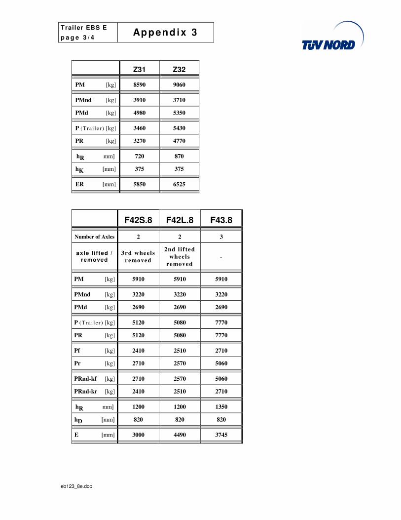
Z31 Z32
PM [kg] 8590 9060
PMnd [kg] 3910 3710
PMd [kg] 4980 5350
P (Tra i le r ) [kg] 3460 5430
PR [kg] 3270 4770
hR mm] 720 870
hK [mm] 375 375
ER [mm] 5850 6525
F42S.8 F42L.8 F43.8
Number of Axles 2 2 3
axle l i f ted / removed
3rd wheels
removed
2nd l if ted
wheels
removed
-
PM [kg] 5910 5910 5910
PMnd [kg] 3220 3220 3220
PMd [kg] 2690 2690 2690
P (Tra i le r ) [kg] 5120 5080 7770
PR [kg] 5120 5080 7770
Pf [kg] 2410 2510 2710
Pr [kg] 2710 2570 5060
PRnd-kf [kg] 2710 2570 5060
PRnd-kr [kg] 2410 2510 2710
hR mm] 1200 1200 1350
hD [mm] 820 820 820
E [mm] 3000 4490 3745

Trailer EBS E
p a g e 4 / 4 Append ix 3
eb123_8e.doc
1.3 Weights (energy consumption tests)
Table “Weights (energy consumption tests) - test vehicles “.8”
EEC Annex XIV worst case loading ECE Annex 19 loading
Trailer P (Trailer)
[kg] PR [kg]
Axle load (average)
[kg]
P (Trailer)
[kg] PR [kg]
Axle load (average)
[kg]
F S 4 1 . 8 * 5180 5180 2590 4710 4710 2355
S 1 2 . 8 10310 5176 2588 9510 4500 2250
S 1 3 . 8 10840 7650 2550 8525 6635 2210
S 2 3 . 8 9960 7560 2520 9340 6980 2330
Z 3 2 . 8 5870 5350 2675 5430 4770 2385
F 4 2 S . 8 5180 5180 2590 4710 4710 2355
F 4 2 L . 8 5080 5080 2540 4550 4550 2275
F 4 3 . 8 7770 7770 2590 7060 7060 2355
F 5 2 . 8 5310 5310 2655 4660 4660 2330
* First axle (of 2-axle full trailer F42) used only as an unbraked dolly axle to simulate a one axle semi-trailer.
Trailer EBS E
p a g e 1 / 3 Append ix 4
eb123_8e.doc
Appendix 4 - Test results
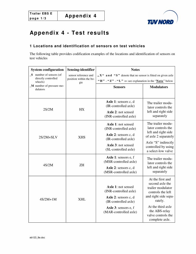
1 Locations and identification of sensors on test vehicles
The following table provides codification examples of the locations and identification of sensors on test vehicles
Notes
„ X “ a n d “ S ” denote that no sensor is fitted on given axle
“ H ” - “ Z ” - “ L ” ⇐ see explanation in the “Note” below
System configuration
_S number of sensors (of directly controlled wheels)
_M number of pressure mo-dulators
Sensing-identifier
sensor reference and position within the bo-
gie
Sensors Modulators
2S/2M HX
Axle 1: sensors c, d (IR-controlled axle)
Axle 2: not sensed (INR-controlled axle)
The trailer modu-lator controls the left and right side
separately
2S/2M+SLV XHS
Axle 1: not sensed (INR-controlled axle)
Axle 2: sensors c, d (IR-controlled axle)
Axle 3: not sensed (SL-controlled axle)
The trailer modu-lator controls the left and right side
of axle 2 separately
Axle “S” indirectly controlled by using a select-low valve
4S/2M ZH
Axle 1: sensors e, f (MSR-controlled axle)
Axle 2: sensors c, d (MSR-controlled axle)
The trailer modu-lator controls the left and right side
separately
4S/2M+1M XHL
Axle 1: not sensed (INR-controlled axle)
Axle 2: sensors c, d (IR-controlled axle)
Axle 3: sensors e, f (MAR-controlled axle)
At the first and second axle the
trailer modulator controls the left
and right side sepa-rately.
At the third axle the ABS-relay
valve controls the complete axle.

Trailer EBS E
p a g e 2 / 3 Append ix 4
eb123_8e.doc
Notes
„ X “ a n d “ S ” denote that no sensor is fitted on given axle
“ H ” - “ Z ” - “ L ” ⇐ see explanation in the “Note” below
System configuration
_S number of sensors (of directly controlled wheels)
_M number of pressure mo-dulators
Sensing-identifier
sensor reference and position within the bo-
gie
Sensors Modulators
4S/3M
semi-trailer LXH
Axle 1: sensors e, f (MAR-controlled axle)
Axle 2 : not sensed (INR-controlled axle)
Axle 3: sensors c, d (MSR-controlled axle)
At the first axle the ABS-relay valve controls the com-
plete axle.
At the second and third axle the
trailer modulator controls the left and right side
separately.
4S/3M
full trailer HL
Axle 1: sensors c, d (MSR-controlled axle)
Axle 2: sensors e, f (MAR-controlled axle)
At the first axle the trailer modulator controls the left
and right side sepa-rately.
At the second axle the ABS-relay
valve controls the complete axle.
N o t e :
“H” means sensors “c” and “d” ( IR-control led axle)
“Z” means sensors “e” and “f” (MSR-controlled axle)
“L” means sensors “e” and “f” (MAR-controlled axle)
“S” means an axle indirectly controlled by using a select- low valve

Trailer EBS E
p a g e 3 / 3 Append ix 4
eb123_8e.doc
2 Test Schedule
The following table defines test schedules by system configuration and trailer types that were considered appropriate for the purpose of an Annex XIV approval.
S e m i - & c e n -t r e a x l e t r a i l e r
1 axle 2 axles 2 axles 3 axles 3 axles 3 axles 3 axles 3 axles
2S/2M H H X X H X H X X X H
2S/2M+SLV H S S H X X H S
4S/2M H Z Z H X H Z Z H X X Z H H Z X Z X H
4S/3M H L L H X H L L H X L X H H X L
4S/2M+1M ���� X H L L H X L X H H X L
F u l l t r a i l e r
4S/3M L H H L L X H L H X H X L
Note: Meaning of the figure ���� see paragraph 3 below.
3 Worst case cross referencing
���� The 4S/2M+1M-system has the same performance as the 4S/3M-system with corresponding configuration.

Trailer EBS E
p a g e 1 / 2 Appendix 4 -1
eb123_8e.doc
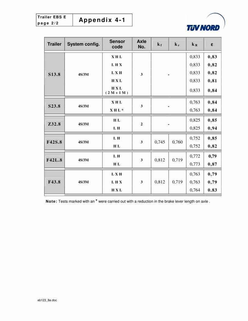
Appendix 4-1 - Ut i l isat ion of adhesion
1 T e s t v e h i c l e s “ . 8 ”
Trailer System config. Sensor code
Axle No.
k f k r k R ε ε ε ε
S11.8 2S/2M H 1 - 0,833 0,90
X H X 0,833 0,82 S13.8 2S/2M
X X H 3 -
0,833 0,81
S21.8 2S/2M H 1 - 0,763 0,90
X H X 0,763 0,78 S23.8 2S/2M
X H X * 3 -
0,763 0,77
S H X _ S L V 0,763 0,81 S23.8 2S/2M
X H S _ S L V 3 -
0,763 0,84
H X 0,825 0,89
X H 0,825 0,83 Z32.8 2S/2M
H S _ S L V
2 -
0,825 0,79
H Z 0,833 0,86 S12.8 4S/2M
Z H 2 -
0,833 0,87
X Z H 0,833 0,83
H Z X 0,833 0,84 S13.8 4S/2M
Z X H
3 -
0,833 0,88
X H Z 0,763 0,79
X H Z * 0,763 0,79 S23.8 4S/2M
Z H X
3 -
0,763 0,83
H Z 0,825 0,94 Z32.8 4S/2M
Z H 2 -
0,825 0,93
Trailer EBS E
p a g e 2 / 2 Appendix 4 -1
eb123_8e.doc
Trailer System config. Sensor code
Axle No.
k f k r k R ε ε ε ε
X H L 0,833 0,83
L H X 0,833 0,82
L X H 0,833 0,82
H X L 0,833 0,81
S13.8 4S/3M
H X L
( 2 M + 1 M )
3 -
0,833 0,84
X H L 0,763 0,84 S23.8 4S/3M
X H L * 3 -
0,763 0,84
H L 0,825 0,85 Z32.8 4S/3M
L H 2 -
0,825 0,94
L H 0,752 0,85 F42S.8 4S/3M
H L 3 0,745 0,760
0,752 0,82
L H 0,772 0,79 F42L.8 4S/3M
H L 3 0,812 0,719
0,773 0,87
L X H 0,763 0,79
L H X 0,763 0,79 F43.8 4S/3M
H X L
3 0,812 0,719
0,764 0.83
Note: Tests marked with an * were carried out with a reduction in the brake lever length on axle .

Trailer EBS E
p a g e 1 / 3 Appendix 4 -2
eb123_8e.doc
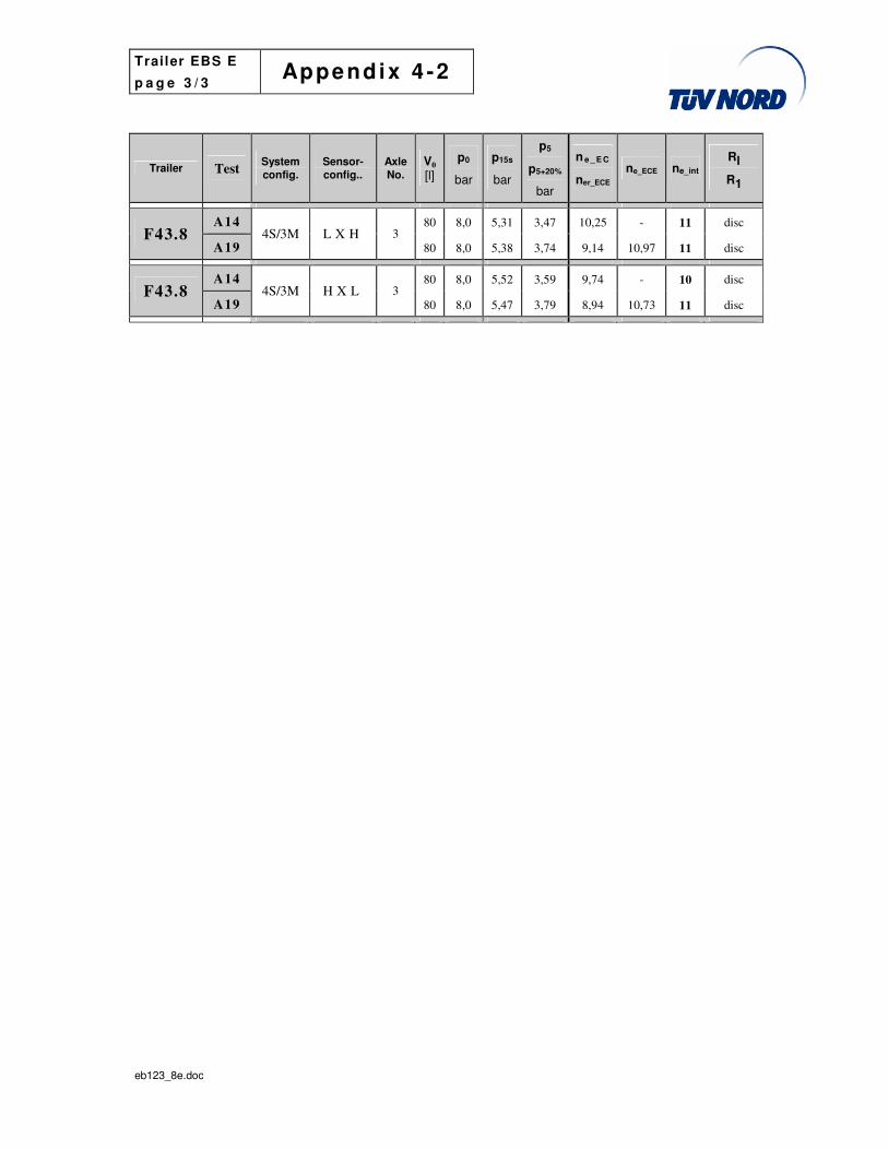
Appendix 4-2 - Energy consumption
1 Test trailers “.8”
Trailer Test System config.
Sensor-config..
Axle No.
V0
[l]
p0
bar
p15s
bar
p5
p5+20%
bar
n e _ E C
ner_ECE ne_ECE ne_int
Rl
R1
A14 100 8,0 6,91 5,99 10,38 - 11 disc FS41.8
A19 2S/2M H 1
100 8,0 6,94 6,07 9,83 11,80 12 disc
A14 8,0 5,58 3,90 9,88 - 10 disc S13.8
A19 2S/2M X H X 3 80
8,0 5,72 4,11 8,93 10,72 11 disc
A14 8,0 5,64 3,94 9,70 - 10 disc S13.8
A19 2S/2M X X H 3 80
8,0 5,65 4,07 9,10 10,92 11 disc
A14 8,0 5,39 3,77 9,32 - 10 0,2 S23.8
A19 2S/2M
X H S S L V
3 80 8,0 5,40 3,78 9,30 11,16 12 0,2
A14 8,0 5,76 4,59 10,93 - 11 0,2 Z32.8
A19 2S/2M H X 2 80
8,0 6,04 4,83 10,04 12,04 13 0,2
A14 8,0 6,04 4,83 10,04 - 11 0,2 Z32.8
A19 2S/2M X H 2 80
8,0 6,42 5,07 8,89 10,67 11 0,2
A14 8,0 6,87 4,74 9,92 10 disc S12.8
A19 4S/2M H Z 3 80
8,0 6,72 5,16 8,03 9,63 10 disc
A14 8,0 6,67 4,75 9,85 10 disc S12.8
A19 4S/2M Z H 3 80
8,0 6,80 5,22 7,82 9,38 10 disc
A14 8,0 5,95 4,00 10,21 - 11 disc S13.8
A19 4S/2M X Z H 3 80
8,0 6,13 4,45 8,36 10,04 11 disc
A14 8,0 5,95 4,00 10,21 - 11 disc S13.8
A19 4S/2M H Z X 3 80
8,0 5,95 4,34 8,77 10,53 11 disc
A14 8,0 6,03 4,04 9,99 - 10 disc S13.8
A19 4S/2M Z X H 3 80
8,0 6,01 4,37 8,64 10,36 11 disc
A14 8,0 5,42 3,79 9,24 - 10 0,2 S23.8
A19 4S/2M X H Z 3 80
8,0 5,67 3,93 8,70 10,44 11 0,2

Trailer EBS E
p a g e 2 / 3 Appendix 4 -2
eb123_8e.doc
Trailer Test System config.
Sensor-config..
Axle No.
V0
[l]
p0
bar
p15s
bar
p5
p5+20%
bar
n e _ E C
ner_ECE ne_ECE ne_int
Rl
R1
A14 8,0 5,31 3,72 9,54 - 10 0,2 S23.8
A19 4S/2M Z H X 3 80
8,0 5,49 3,84 9,05 10,86 11 0,2
A14 8,0 5,95 4,73 10,25 - 11 0,2 Z32.8
A19 4S/2M H Z 2 80
8,0 5,97 4,74 10,18 12,21 13 0,2
A14 8,0 5,77 4,60 10,89 - 11 0,2 Z32.8
A19 4S/2M Z H 2 80
8,0 5,79 4,62 10,82 12,99 13 0,2
A14 8,0 5,60 3,79 10,19 - 11 disc S13.8
A19 4S/3M X H L 3 80
8,0 5,74 4,10 8,87 10,64 11 disc
A14 8,0 5,61 3,79 10,16 - 11 disc S13.8
A19 4S/3M L H X 3 80
8,0 5,53 3,97 9,39 11,27 12 disc
A14 8,0 5,73 3,87 9,83 - 10 disc S13.8
A19 4S/3M L X H 3 80
8,0 5,45 3,92 9,61 11,53 12 disc
A14 8,0 5,48 3,71 10,55 - 11 disc S13.8
A19 4S/3M H X L 3 80
8,0 5,75 4,10 9,85 11,82 12 disc
A14 8,0 5,67 3,78 9,95 - 10 0,2 S13.8
A19 4S/3M
H X L 2M+1M
3 80 8,0 6,19 4,32 8,83 10,60 11 0,2
A14 8,0 5,80 4,62 10,79 - 11 0,2 Z32.8
A19 4S/3M H L 2 80
8,0 6,04 4,79 9,93 11,91 12 0,2
A14 8,0 5,82 4,64 10,71 - 11 0,2 Z32.8
A19 4S/3M L H 2 80
8,0 5,80 4,62 10,79 12,94 13 0,2
A14 80 8,0 6,25 0,00 10,36 - 11 disc F42S.8
A19 4S/3M L H 2
80 8,0 6,17 0,00 9,69 11,63 12 disc
A14 80 8,0 6,17 0,00 10,57 - 11 disc F42S.8
A19 4S/3M H L 2
80 8,0 6,22 0,00 9,57 11,49 12 disc
A14 80 8,0 5,73 4,14 10,70 - 11 disc F42L.8
A19 4S/3M L H 2
80 8,0 5,81 4,38 9,61 11,53 12 disc
A14 80 8,0 6,15 4,31 9,59 - 10 disc F42L.8
A19 4S/3M H L 2
80 8,0 6,38 4,67 9,07 10,09 11 disc
Trailer EBS E
p a g e 3 / 3 Appendix 4 -2
eb123_8e.doc
Trailer Test System config.
Sensor-config..
Axle No.
V0
[l]
p0
bar
p15s
bar
p5
p5+20%
bar
n e _ E C
ner_ECE ne_ECE ne_int
Rl
R1
A14 80 8,0 5,31 3,47 10,25 - 11 disc F43.8
A19 4S/3M L X H 3
80 8,0 5,38 3,74 9,14 10,97 11 disc
A14 80 8,0 5,52 3,59 9,74 - 10 disc F43.8
A19 4S/3M H X L 3
80 8,0 5,47 3,79 8,94 10,73 11 disc
Trailer EBS E
p a g e 1 / 2 Appendix 4 -3
eb123_8e.doc
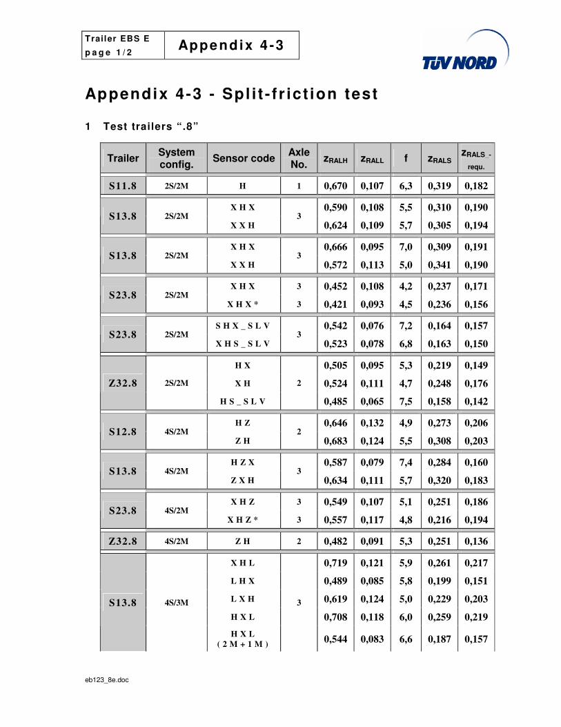
Appendix 4-3 - Spl i t - f r ict ion test 1 Test trailers “.8”
Trailer System config.
Sensor code Axle No.
zRALH zRALL f zRALS zRALS_-
requ.
S11.8 2S/2M H 1 0,670 0,107 6,3 0,319 0,182
X H X 0,590 0,108 5,5 0,310 0,190 S13.8 2S/2M
X X H 3
0,624 0,109 5,7 0,305 0,194
X H X 0,666 0,095 7,0 0,309 0,191 S13.8 2S/2M
X X H 3
0,572 0,113 5,0 0,341 0,190
X H X 3 0,452 0,108 4,2 0,237 0,171 S23.8 2S/2M
X H X * 3 0,421 0,093 4,5 0,236 0,156
S H X _ S L V 0,542 0,076 7,2 0,164 0,157 S23.8 2S/2M
X H S _ S L V 3
0,523 0,078 6,8 0,163 0,150
H X 0,505 0,095 5,3 0,219 0,149
X H 0,524 0,111 4,7 0,248 0,176 Z32.8 2S/2M
H S _ S L V
2
0,485 0,065 7,5 0,158 0,142
H Z 0,646 0,132 4,9 0,273 0,206 S12.8 4S/2M
Z H 2
0,683 0,124 5,5 0,308 0,203
H Z X 0,587 0,079 7,4 0,284 0,160 S13.8 4S/2M
Z X H 3
0,634 0,111 5,7 0,320 0,183
X H Z 3 0,549 0,107 5,1 0,251 0,186 S23.8 4S/2M
X H Z * 3 0,557 0,117 4,8 0,216 0,194
Z32.8 4S/2M Z H 2 0,482 0,091 5,3 0,251 0,136
X H L 0,719 0,121 5,9 0,261 0,217
L H X 0,489 0,085 5,8 0,199 0,151
L X H 0,619 0,124 5,0 0,229 0,203
H X L 0,708 0,118 6,0 0,259 0,219
S13.8 4S/3M
H X L
( 2 M + 1 M )
3
0,544 0,083 6,6 0,187 0,157

Trailer EBS E
p a g e 2 / 2 Appendix 4 -3
eb123_8e.doc
Trailer System config.
Sensor code Axle No.
zRALH zRALL f zRALS zRALS_-
requ.
X H L 3 0,495 0,105 4,7 0,215 0,164 S23.8 4S/3M
X H L * 3 0,472 0,100 4,7 0,188 0,156
Z32.8 4S/3M L H 2 0,473 0,100 4,7 0,194 0,140
L H 0,533 0,096 5,6 0,179 0,162 F42S.8 4S/3M
H L 2
0,420 0,085 5,5 0,171 0,139
L H 0,601 0,104 5,8 0,197 0,194 F42L.8 4S/3M
H L 2
0,626 0,107 5,8 0,229 0,181
L X H 0,519 0,093 5,6 0.191 0,170 F43.8 4S/3M
H X L 3
0,596 0,092 6,5 0,192 0,175
Road surface: wet blue basalt / d ry asphalt
Test speed: 50 km/h
No inadmissible locking or inadmissible course deviation was observed during any of the above listed split-friction tests.
Ratio f = zRALH / zRALL

Trailer EBS E
p a g e 1 / 1 Appendix 4 -4
eb123_8e.doc
Appendix 4-4 - Addit ional checks Test trailers “.8”
1 Low speed performance
The tests described in Section 6.3.1 of Annex X to Directive 71/320/EEC and Annex 13 to ECE-Regulation No. 13 respectively were carried out on all unladen test trailers defined in Appendix 3 of this report with each anti-lock configuration.
All tests were carried out on a dry asphalt surface from an initial speed of 40 km/h.
When the brakes were suddenly actuated there was no locking of any directly controlled wheel at speeds v > 15 km/h or course deviation at any speed.
2 High speed performance
The tests described in Section 6.3.1 of Annex X to Directive 71/320/EEC and Annex 13 to ECE-Regulation No. 13 respectively were carried out on all the above defined unladen test trailers with each anti-lock configuration.
All tests were carried out on a dry asphalt surface from an initial speed of 80 km/h.
When the brakes were suddenly actuated there was no locking of any directly controlled wheel at speeds v > 15 km/h or course deviation at any speed.
3 Transition from high to low adhesion surfaces
Road surface: dry asphalt / wet steel plates
Test speeds: 40 km/h and 80 km/h
Observations: - no locking of any directly controlled wheel at v > 15 km/h
- vehicle stable with no deviation from the intended course
- in all cases the anti-lock systems reacted rapidly to the change in tyre to road surface adhesion
4 Transition from low to high adhesion surfaces
Road surface: wet steel plates / dry asphalt
Test speed: 50 km/h
Observations: - no locking of any directly controlled wheel at v > 15 km/h
- vehicle stable with no deviation from the intended course
- in all cases the anti-lock system reacted to the change in tyre to road sur-face adhesion within a time of 0,4 s to 1,0 s

Trailer EBS E
p a g e 1 / 4 Append ix 5
eb123_8e.doc
Appendix 5 - Further test resul ts
1 Tyre to exciter relationship
Paragraph 4.1.4.2 of Annex XIV to Directive 71/320/EEC and paragraph 5.4.1.4.2 of annex 19 to ECE-Regulation No. 13 require that the functional checks defined in paragraph 6.3 of Annex X to Directive 71/320/EEC and of Annex 13 to ECE-Regulation No. 13 be carried out with the ex-tremes of tolerance of the recommended range of tyre size for a pole wheel with a given number of teeth.
The “Trailer EBS” takes into account the actual tyre rolling circumference and the number of ex-citer teeth (which are stored in the ECU prior to entry into service) of the individual trailer.
Thus only the inter-wheel variations of the rolling circumference of 6,5 % permitted by the manufacturer (see paragraph 2.4 of ID_TEBS) were assessed.
The following tables contain the respective 40 to 20 km/h deceleration times for the optimum cir-cumference variation of 0 % and the tolerances of ± 7 % ascertained on a high friction surface with the test trailers S13.8 and S23.8 with the configuration 2S/2M_XHX.
Tyre rolling circumference
S13.8 3200 mm 3425 mm 2975 mm
Circumference variation 0 % + 7 , 0 3 % - 7 , 0 3 %
Test order 1st measurement 2nd measurement 3rd measurement
Number of exciter teeth 90 90 90
2,168 2,126 2,057
2,052 2,123 2,141
40 to 20 km/h time (t)
2,351 2,339 2,193
average (t ime t) 2,190 2,196 2,130
deviation of t in % 0 % + 0,3 % - 2,7 %

Trailer EBS E
p a g e 2 / 4 Append ix 5
eb123_8e.doc
Tyre rolling circumference
S23.8 3200 mm 3425 mm 2975 mm
Circumference variation 0 % + 7 , 0 3 % - 7 , 0 3 %
Test order 1st measurement 2nd measurement 3rd measurement
Number of exciter teeth 100 100 100
2,496 2,506 2,542
2,279 2,208 2,435
40 to 20 km/h time (t)
2,490 2,427 2,278
average (t ime t) 2,412 2,380 2,418
deviation of t in % 0 % - 1,3 % + 0,3 %
2 Differential(s) in brake input torque within a trailer bogie
Within Appendices 4-1 and 4-3 of this report reference is made to tests carried out where the brake input torque was reduced on axle 1 to take account of dynamic load transfer within the bo-gie during braking.
3 Tube sizes and lengths
To assess the influence of the recommendations contained within ID_TEBS response tests were carried out with the delivery tubes specified. Anti-lock performance was then verified at the ex-tremes of tube size recommended.
3.1 Time measurement
The manufacturer’s Information Document states that the maximum length of tube for a directly and a indirectly controlled wheel shall be limited to 6 m. However in all cases the prescribed sys-tem response times must be fulfilled. To verify this statement it was considered appropriate to compare differences in system response and anti-lock performance relative to the tube length from the modulator to the brake chamber.
The following time measurements were obtained from a 3-axle full trailer representing the test-ing conditions of the ABS-performances specified in the table of paragraph 3.2 below. The tube lengths to either a directly controlled axle or indirectly controlled axles were increased according to the maximum tube length of 6,0 m as specified by the manufacturer in paragraph 3.5 of ID_TEBS.

Trailer EBS E
p a g e 3 / 4 Append ix 5
eb123_8e.doc
Axle 1 Axle 2 Axle 3
Delivery tube lengths [∅∅∅∅i = 13 mm]: 5,4 m 2,2 m 3,9 m
Response t ime (pneumatic / CAN): 0,39 / 0,35 s 0,34 / 0,27 s 0,35 / 0,28 s
Delivery tube lengths [∅∅∅∅i = 13 mm]: 6,0 m 6,0 m 6,0 m
Response t ime (pneumatic / CAN): 0,41 / 0,36 s 0,37 / 0,31 s 0,39 / 0,31 s
3.2 Anti-lock performance
The following test results were obtained from a three axle full trailer installed with a 4S/3M_LXH system where the tube lengths represented a “standard installation” and installa-tions where the delivery tube lengths were increased to 3 and 6 m respectively (motor vehicle unbraked).
F43_unl ⇒⇒⇒⇒ unladen trailer weight: 6395 kg
F43_lad ⇒⇒⇒⇒ laden trailer weight: 16360 kg
A B S p e r f o r m a n c e
t z R A L [s] axle 1
(directly controlled) axle 2
(indirectly controlled) axle 3
(directly controlled)
F 4 3 _ u n l s tandard tube l ength
2,638
2,641
2,702
Average 2,660
5,4 m 2,2 m 3,9 m
F 4 3 _ u n l increased tube leng th
2,689
2,664
2,712
Average 2,688
6,0 m 6,0 m 6,0 m
F 4 3 _ l a d s tandard tube l ength
1,912
1,989
1,996
5,4 m 2,2 m 3,9 m
Average 1,966
F 4 3 _ l a d increased tube leng th
2,173
1,992
1,998
Average 2,054
6,0 m 6,0 m 6,0 m

Trailer EBS E
p a g e 4 / 4 Append ix 5
eb123_8e.doc
All comparison tests were carried out on a dry asphalt surface.
The above tests with the various tube length variations show that the utilisation of adhesion times t z R A L are within the following tolerances:
a) Comparison between the standard and increased tube length condition in relation to the
respective mean values for the unladen and laden state:
For the unladen state the deviation was ±±±± 0 . 5 2 % and for the laden state the deviation was ±±±± 2 . 1 9 % .
b) Variation of the test results in relation to the respective mean values for the unladen and
laden state:
For the unladen state the measured utilisation of adhesion times lay in a tolerance band of 2.8 % whereas for the laden state the tolerance band was 1 3 % .