training at diesel locomotive works
DESCRIPTION
Electrical engineering training report done during summer internship 2013TRANSCRIPT

A
Industrial Training REPORT
UNDERTAKEN AT
DIESEL LOCOMOTIVE WORKS
VARANASI
Submitted in partial fulfillment of the
Requirement for the award of the degree of
BACHELOR OF TECHNOLOGY
IN
ELECTRICAL AND ELECTRONICS ENGINEERING
SUBMITTED BY: - SUBMITTED TO:-
VIVEK KUMAR THAKUR MR.AMIT KUMAR
(ROLL NO. -10060108042) (ASST. PROFESSOR)
DEPARTMENT OF ELECTRICAL ENGINEERING
College of Engineering Roorkee, Roorkee
(Uttarakhand Technical University, Dehradun)
SESSION 2013-2014

CANDIDATE DECLARATION
I hereby, declare that I have successfully completed the Industrial Training at “DIESEL
LOCOMOTIVE WORK” for fulfillment of the award of degree of Bachelors of Technology
as prescribed by the Uttarakhand Technical University, Dehradun.
I also declare that I did not copy the Training Report from anywhere this is my genuine work.
Date: Name:- Vivek Kumar Thakur
Place: Roll No.:-10060108042

ACKNOWLEDGEMENT
An Engineer with only theoretical knowledge is not a complete engineer. Practical knowledge is
very important to develop and apply engineering skills. It gives me a great pleasure to have an
opportunity to acknowledge and to express gratitude to those who were associated with me
during my training at DLW, Varanasi.
Special thanks to MR.SATYENDRA SINHA for providing me an opportunity to undergo
training under his able guidance and offering me a very deep knowledge of practical aspects of
industrial work culture.
I express my sincere thanks and gratitude to DLW authorities for allowing me to undergo the
training in this prestigious organization. I will always remain indebted to them for their constant
interest and excellent guidance in my training work, moreover for providing me with an
opportunity to work and gain experience.

TABLE OF CONTENTS
1) INTRODUCTION
2) BRIEF HISTORY
3) CLASSIFICATION OF LOCOMOTIVES
4) MANUFACTURING PROCESS
ENGINE DIVISION
VEHICLE DIVISION
BLOCK DIVISION
5) WORKSHOPS
TRACTION ASSEMBLY WORKSHOP
MAIN RECEIVING STATION
6) DESIGN AND DEVELOPMENT CAPABILITIES
7) CONCLUSION

INTRODUCTION
The Diesel Locomotive Works (DLW) in Varanasi, India, is a production unit owned
by Indian Railways that manufactures diesel-electric locomotives and its spare parts. It is
the largest diesel-electric locomotive manufacturer in India.
Founded in 1961, the DLW rolled out its first locomotive three years later, on January 3,
1964. It manufactures locomotives which are variants based on the
original ALCO designs dating to 1960s and the GM EMD designs of the 1990s.DLW has
an annual production capacity of 250 locomotives and plans to increase it to 275 based on
the current demand.
PRODUCTS: DLW locomotives have power outputs ranging from 2,600 horsepower
0(1,900 kW) to 5,500 horsepower (4,100 kW). Currently DLW is producing EMD
GT46MAC and EMD GT46PAC locomotives.

MARKET: Besides the Indian Railways, it regularly exports diesel-electric
locomotives and has supplied locomotives to other countries such as Sri
Lanka, Malaysia, Bangladesh, Mali, Senegal, Sudan, Tanzania, Angola, and Vietnam and
also to a few users within India, such as ports, large power and steel plants and private
railways.
ANCILLARY: In July 2006, DLW outsourced manufacture of some passenger and
freight locomotives to Parel Workshop, Central Railway, and Mumbai.

BRIEF HISTORY
August 1961 DLW set up as a green field project in technical collaboration with ALCO,
USA for manufacture of Diesel Electric Locomotives
January 1964 First Locomotive rolled out and dedicated to the Nation
January 1976 Entered Export market, first locomotive exported to Tanzania
December 1977 First Diesel Generating Set commissioned
October 1995 The Transfer of Technology agreement was signed
March 2002 The first indigenous EMD WDG4 freight loco manufactured
November 2002 3600 HP Engine produced
March 2003 The first indigenous passenger version of EMD loco WDP4 manufactured
September 2003 Development of 16 cylinder 3300 HP Power upgraded DLW engine,
WDM3D locomotive
2006 5000th locomotive produced
November 2006 DLW manufactured first WDG4 locomotive equipped with IGBT based
converter
March 2007 First WDP4 locomotive equipped with IGBT based converter
April 2007 DLW has successfully switched over to use of microprocessor based control
system on all its locomotives.
March 2009 257 locomotives manufactured in 2008-09, highest ever locomotive
production
November 2009 5690 locomotives up to 30th Nov‟2009(including 348 EMD locos)

CLASSIFICATION OF LOCOMOTIVES
The classification syntax used for identification of locos is:
“ [ gauge ][ power ][load ][ series ][ sub type ][ suffix ] ”
The first letter (gauge)
W- Indian broad gauge
Y- Meter gauge
Z- Narrow gauge (2.5 ft)
N- Narrow gauge (2 ft)
The second letter (motive power)
D- Diesel
C- DC electric (can run under DC traction only)
A- AC electric (can run under AC traction only)
CA- Both DC and AC (can run under both AC and DC tractions);
'CA' is considered a single letter
B- Battery electric locomotive (rare)
The third letter (load type)
G-goods
P-passenger
M-mixed traffic; both goods and passenger
S-Used for shunting
U-Electric multiple units (E.M.U.)
R-Railcars
The fourth letter (series)
The series digit identifies the horsepower range of the locomotive. Example for the series letter
„3‟ means that the locomotive has power over 3000 horse power but less than 4000 hp.
The fifth letter (subtype)
An optional letter or number that indicates some smaller variations in the basic model.
For ex: „A‟ for 100 horse power,
„B‟ for 200 horse power and so on……..

MANUFACTURING PROCESS
DLW rolled out its first locomotive on 3rd Jan 1964.Since, then it is manufacturing locomotives.
Currently, its annual production capacity is of 250 locomotives .The Manufacturing Process of
Diesel Locomotive Works, Varanasi is divided into 3 divisions:
Engine Division
Vehicle Division
Block Division.
ENGINE DIVISION
It is again divided into 2 categories:
Component Machining
Engine Assembly.
Component Machining:
Over 2000 components are manufactured in-house at DLW. These include ALCO turbo
superchargers, lubricating oil pumps, cam shafts, cylinder heads, laser hardened cylinder liners,
connecting rods and various gears. Our well-equipped Machine Shop have dedicated lines for
operations like turning, milling, gear hobbling, drilling, grinding and planning etc. In addition,
DLW is equipped with a variety of special purpose machines and a large number of State-of-the-
art CNC machines to ensure quality and precision. Associated manufacturing process like heat

treatment and induction hardening are also carried out in-house. A new eco-friendly laser
hardening machine has been setup which is designed to laser harden the inner bore of engine
cylinder liner and this feature advantages such as low running cost, state of the art controls to
provide reliable and versatile laser power for ultimate quality requirements.
Engine Assembly & Testing:
Pre-inspected engine block, crankshaft, cylinder liners, pistons, connecting rods, cylinder heads,
exhaust manifold, turbo supercharger and all related piping are used in assembly of engine.
Electrical machines like traction alternator, auxiliary generator and exited are thereafter coupled
on the engine. The complete power pack with electrics are tested on computerized Engine Test
Bed to verify prescribed horsepower output. Vital parameters of engine health are checked to
assure the quality of product. Only after the engine parameters are found perfect the power pack
are cleared for application on locomotives.

VEHICLE DIVISION
It includes following processes:
Component Fabrication
Under frame Fabrication
Bogie Manufacturing
Locomotive Assembly
Component Fabrication:
Precision cutting and forming of sheet metal is utilized for manufacture of superstructures
including drivers cab engine hoods, and compartments for housing electrical equipment.
All activities connected with pipes like pickling, bending,
Cutting, forming and threading of pipes of various sizes are undertaken in another well-
equipped work area. All electrical equipment is assembled in the fabricated control
compartments and driver's control stands are done in another work area.

Under frame Fabrication:
Under frames are fabricated with due care to ensure designed weld strength. Requisite camber to
the under frame is provided during fabrication itself. Critical welds are tested radio-graphically.
Welder training and their technical competence are periodically reviewed. High Horse Power
(HHP) under frame is fabricated using heavy fixtures, positioners to ensure down hand welding.
Fixtures are used to ensure proper fitting of components and quality welding in subsequent
stages.

Bogie Manufacturing:
Special purpose machines are utilized for machining cast and fabricated bogie frames. Axle and
wheel disc machining is undertaken on sophisticated CNC machines. Inner diameter of wheel
discs are matched with the outer diameter of axles and assembled on wheel press. The complete
truck (bogie), including bogie frames, wheels and axles, brake rigging and traction motors are
assembled which is ready for application to locomotive.
Locomotive Assembly:
Tested engines are received from Engine Division. Similarly under frames are received from
Loco frame shop and assembled trucks from Truck machine shop. Superstructure compartments
and contractor compartment are received from respective manufacturing and assembly shops of
Vehicle Division. Important alignments like crank shaft deflection; compressor alignment and
Eddy Current clutch/radiator fan alignment are done during assembly stage.

Electrical control equipment's are fitted and control cable harnessing is undertaken. The
complete locomotive is thus assembled before being sent onwards for final testing and spray
painting. All locomotive are rigorous tested as per laid down test procedures before the
locomotive is taken up for final painting and dispatch for service.
BLOCK DIVISION
It includes following processes:
Flame Cutting of Components
Fabrication of Engine Block/Crankcase
Portal Milling Machine
Angular Boring Machine
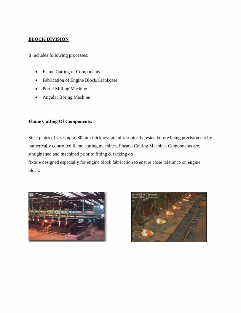
Flame Cutting Of Components:
Steel plates of sizes up to 80 mm thickness are ultrasonically tested before being precision cut by
numerically controlled flame cutting machines, Plasma Cutting Machine. Components are
straightened and machined prior to fitting & tacking on
fixture designed especially for engine block fabrication to ensure close tolerance on engine
block.

Fabrication of Engine Block/Crankcase:
Components after flame cutting and various machining operations are fit and tack welded before
taking on rollovers. Heavy Argon-CO2 welding is done on these rollovers. High quality of
welding is done by qualified welders. Weld joints are subjected to various tests like ultrasonic,
X-rays, Visual etc. Down-hand welding is ensured using specially designed positioners.
Fabrication of engine block is completed by submerged arc welding using semi-automatic
welding machines. Special fixtures are used for making down-hand welding possible in
inaccessible areas. Critical welds are subjected to radiographic examination. All welders are
periodically tested and re-qualified for the assigned. After complete welding weldment is stress
relieved and marking is done for subsequent machining.
Portal Milling Machine:
Engine block machining is done on Portal Milling Machine which is a 5 axis CNC machine with
SIEMENs 840-D state of art system control with dedicated tool management system. This
machine performs milling, drilling, tapping and boring operations in single setting. The machine
accuracy of 10 micro enables adhering to the tolerance required on engine block.

Angular Boring Machine:
Angular boring "V" boring is done of special purpose machine which is a special purpose
machine, which has two high precision angular boring bars on which different boring inserts are
mounted. The cutting inserts on boring bars to achieve evenly distributed cutting load during
boring operation. This contributes to accuracy while machining. Boring bars are mounted on
high precision bearings which provide control on size during angular boring. The machine is
capable of boring and drilling to different sizes.

WORKSHOPS
The workshops attended during the training at DLW are:
TAS (Traction Assembly Shop), and
MRS (Main Receiving Station).
TRACTION ASSEMBLY SHOP (TAS):
TAS is the unit in which all the locomotive parts are assembled, that includes:
1. CP (Control Panel)
2. Alternator
3. Traction Motors
4. 16 cylinder Diesel Engine
5. Master Control
6. Cab
7. Auxiliary Generator & Exciter
8. Governor
9. Crank Case Exhauster
10. Mechanical Assembly.

Control Panel:
The CP or the Control Panel (with respect to WG3A loco) consists of:
a) Control Switch
b) Display Unit
c) LED Panel
d) Microprocessor based Control Unit
e) Reverser
f) BKT
g) Valves
h) Hooter
i) CK1/CK2/CK3
The top portion of CP has sensors and relays connected to the microprocessor unit. The display
unit of microprocessor shows working condition of items in engine. The LED Panel displays the
overload, auxiliary generator failure, hot engine, rectilinear fuse blown, etc. The battery ammeter
shows the charging state of the batteries. REV: Field wiring goes to reverser (REV) and hence it
is used to control the polarity of the field which in turn controls the direction of train. BKT: It is
a switch which in one direction is used to motor the loco while in other it is used for dynamic
braking. Microprocessor based Control Unit: On-board microprocessors control engine speed,
fuel injection, and excitation of the alternator. These computers also interconnect with improved
systems to detect slipping or sliding of the driving wheels, producing faster correction and
improved adhesion. An additional function of the microprocessor is to monitor performance of
all locomotive systems, thereby increasing their reliability and making the correction of
problems easier.

Hooter: It is a vigilance control device (VCD) to keep the driver alert. If the driver isn‟t doing
anything with the controls for over a minute, the hooter „hoots‟ and brings the engine speed to
the normal speed (low) without asking the driver. It can only be reset after 2 minutes and hence
the driver will be held responsible for delay in reaching the next station.
Dynamic braking:
It is the use of the electric traction motors of a railroad vehicle as generators when slowing the
vehicle. It is termed rheostat if the generated electrical power is dissipated as heat in brake grid
resistors, and regenerative if the power is returned to the supply line. Dynamic braking lowers
the wear of friction-based braking components, and additionally regeneration can also lower
energy consumption.
During braking, the motor fields are connected across either the main traction generator (diesel-
electric loco) or the supply (electric locomotive) and the motor armatures are connected across
either the brake grids or supply line. The rolling locomotive wheels turn the motor armatures,
and if the motor fields are now excited, the motors will act as generators.
For a given direction of travel, current flow through the motor armatures during braking will be
opposite to that during motoring. Therefore, the motor exerts torque in a direction that is
opposite from the rolling direction. Braking effort is proportional to the product of the magnetic
strength of the field windings, times that of the armature windings.
In DLW Locomotives the braking method used is rheostatic, i.e. the traction motors behave as
generators (separately excited) and their electrical power is dissipated in brake grid resistors.
This method is used for minimizing speed of the loco. The loco actually comes to a halt due to
factors like air resistance, friction with the rail, etc.

Alternator:
An alternator converts kinetic energy (energy of motion) into electrical energy. All recently
manufactured automobiles rely on alternators to charge the battery in the ignition system and
supply power to other electrical equipment. Alternators are sometimes called AC generators
because they generate alternating current (AC).
Electric current can be generated in two ways: The magnet may rotate inside the coil, or the coil
may rotate in a magnetic field created by a magnet. The component that remains stationary is
called the stator, and the component that moves is called the rotor. In alternators, the coil is the
stator and the magnet is the rotor. A source of mechanical power, i.e. the diesel engine turns the
rotor.
In WDM-3D and WDM-3A locos, the diesel engine‟s mechanical output is used to run the shaft
of the Alternator. The alternating output of the Alternator is then rectified to DC via solid-state
rectifiers and is fed to traction motors (DC) that run the loco wheels. Thus they operate on AC-
DC Traction mechanism. WDG4 and WDP4 locos have AC-AC traction with microprocessor
control, i.e. AC Traction motors are used thus eliminating the motor commutator and brushes
The result is a more efficient and reliable drive that requires relatively little maintenance and is
better able to cope with overload conditions.
Why not feed direct DC to the traction motors via DC generators?
In a DC generator, the rotor is the coil. Alternators normally rotate the magnet, which is lighter
than the coil. Since alternators are built to spin the lighter component instead of 10 the heavier
one, they generally weigh only one-third as much as generators of the same capacity.

DC generators, in particular, require more maintenance because of wear on the parts that brush
against one another in the commutator switch and the stress of rotating the heaviest component
instead of the lightest. Also, when generators are run at higher speeds, electricity tends to arc, or
jump the gap separating metal parts. The arcing damages parts and could make generators
hazardous to touch. Alternators can run at high speeds without arcing problems.
Traction Motor:
It‟s an electric motor providing the primary rotational torque of the engine, usually for
conversion into linear motion (traction). Traction motors are used in electrically powered rail
vehicles such as electric multiple units and electric locomotives, other electric vehicles such as
electric milk floats, elevators and conveyors as well as vehicles with electrical transmission
systems such as diesel-electric and electric hybrid vehicles. Traditionally, these are DC series-
wound motors, usually running on approximately 600 volts.
16 Cylinder Diesel Engines:
It is an internal-combustion engine in which heat caused by air compression ignites the fuel. At
the instant fuel is injected into a diesel engine‟s combustion chambers, the air inside is hot
enough to ignite the fuel on contact. Diesel engines, therefore, do not need spark plugs, which
are required to ignite the air-fuel mixture in gasoline engines. The Diesel engine has 16
cylinders. Pistons inside the cylinders are connected by rods to a crankshaft. As the pistons move
up and down in their cylinders, they cause the crankshaft to rotate. The crankshaft‟s rotational
force is carried by a transmission to a drive shaft, which turns axles, causing mechanical output.
Eight 8V and four 2V Batteries are used in series to run a more powerful starter motor, which
turns the crankshaft to initiate ignition in a diesel engine for the first time.

Master Control:
It‟s the unit that has the handles to regulate the speed of the loco as well as the direction of
motion. It has numbering from 0-9 and each increment causes rise in speed in forward direction.
It can also be used to reverse the direction of motion by pushing the handle in the opposite sense.
It is present on the control desk of the cab.
Cab:
It‟s the driver‟s cabin with 2 control desks, the Control Panel (CP) and chairs for the driver.
The Cab is at one end of the locomotive with limited visibility if the locomotive is not operated
cab forward. Each control desk has the Independent SA9 brake for braking of the engine alone
and Auto Brake A9 for the braking of the entire loco. It also has the following components:
LED Panel,
Buttons of various engine LED lights (front and side),
Automatic stand throw button (to prevent sliding of wheels on inclined planes),
Master Control,
Gauges to monitor booster air, fuel and lube pressure,
Speedometer,
Service Brakes (Independent and Auto brakes described above), and
Emergency Brake (Type of Air brake to halt the train in the distance nearly equal to the
length of the train, to be used only during an emergency).

Auxiliary Generator and Exciter:
The Alternator has these two components. The exciter and the auxiliary generator consist of two
armatures on a single shaft. The auxiliary generator supplies a constant voltage of around 72V
for supplying power to charge the battery for the control equipment and to power the locomotive
lights. The Exciter supplies excitation for the main generator. Starting of Engine The supply
from the batteries is given to the exciter. The exciter has armature and field windings. Hence it
starts rotating as it receives the supply voltage. The Exciter is coupled with the rotor of the
alternator which in turn is connected with the propeller shaft. When the propeller rotates at a
particular rpm, the engine gets started. It‟s just like starting a bike. The „kick‟ must be powerful
enough to start its engine. Later the engine runs on diesel oil (fuel). As soon as the engine starts,
the auxiliary generator also coupled with the alternator starts charging the batteries. Its potential
is maintained at ~72V.
Governor:
It is the device that has the following functions:
1. To control engine speed
2. Deliver fuel (Diesel oil) according to load
3. To mediate electrical demand and diesel engine output.
Crank case exhauster:
It is the device used to evacuate the diesel engine chamber.
Mechanical Assembly:
All mechanical parts on the engine apart from the above mentioned units may be grouped in this
category. It essentially consists of:
Base frame
Wheels
Air Brakes
Batteries
Sand Box
Vacuum brakes
Fuel tank (Loco fuel oil tank capacity is 3000L) etc.
Air Braking System of Locomotives: On a train, the brake shoes are pressed directly against the
wheel rim. A compressor generates air pressure that is stored in air tanks. 12
Air hoses connect the brakes on all the train cars into one system. Applying air pressure into the
system releases the brakes, and releasing air pressure from the system applies the brakes.

MAIN RECEIVING STATION (MRS):
It is the power station of entire DLW. It works as follows:
It receives main supply from UPPCL at 33 kV.
This is step down with 7.5 MVA transformers. The 33 kV feeder is transformed into three 11kV
feeder with a bus coupler in between.
The MRS follows the ring type distribution system for supplying power to DLW. The advantage
of this system is that each substation is fed from two sides. If in case one line is faulted then the
substation is fed by other line.
BLOCK DIAGRAM OF MRS

Main components of MRS are:
Transformer: Different types of transformer used in MRS are Potential Transformer,
Current transformer and Distribution Transformer.
Relays: They are used for protection of the power system from different faults occurring
in the power system. It is a simple electromechanical switch made of electromagnets and
a set of contacts. Relays used in MRS are definite relay and inverse relay.
Capacitor Bank: In the electrical system power factor play an important role because by
improving the power factor one can reduce the losses. To improve power factor,
capacitor bank are placed in parallel with the power supply. In DLW, 600KVAR
capacitor bank is used for the improvement of power factor.

DESIGN & DEVELOPMENT CAPABILITIES
DLW has a design and development office responsible for all engineering functions related to
diesel locomotives. Equipped with extensive designing tools, this office provides service support
to Zonal Railways / Diesel Locomotive Maintenance Sheds and Locomotive Overhauling
Workshops. This office is also responsible for product development, vendor development and
vendor approval. It also performs technical advisory functions and coordination with
RDSO/Railway Board on technical matters.
Functional Responsibilities:
All design issues of ALCO and HHP locomotives. Moreover, design up gradation of
HHP locomotives like power up gradation to 4500 BCV, incorporation of IGBT based
technology, Distributed power, Hotel Load, Development of twin cab WDP4 and are
being dealt with by Design Office.
Liaison with CQAM and RITES in respect of inspection and quality control standards.
Up gradation of technology and quality systems with a view to reducing maintenance and
increasing reliability and availability of locomotives.
Any new project which is taken up by Marketing for NRC/Export through RITES is
basically dealt by Design Office either independently or in consultation with RDSO. In
case of RDSO design, key designs are circulated with complete manufacturing details
with associated specifications by Design Office. Moreover, Design Office provides all
the technical information to the Marketing for any proposed project.

Requirements for design of a new diesel electric locomotive for export / NRC.
Complete design documentation control like specification, drawings, Maintenance
Instructions, Diesel Maintenance Spare Parts Catalogue, Vendor Directory, Design
Publication disseminating information to the Zonal Railways.
Major Locomotive Design Projects:
A. Projects currently in hand:
1. HHP
4500 HP Locomotive with M/s Siemens make AC-AC traction system and Hotel Load
capability.
4500 HP WDP4D Dual Cab Locomotive with M/s Siemens makes AC-AC traction
system.
4500 HP Dual cab freight locomotive.
2. ALCO
3100 HP AC-DC Locomotive for Bangladesh Railways.
3100/3300 HP WDG3A/WDM3D loco with Computer Controlled Braking (CCB).

1350 HP WDSADT Locomotive with Microprocessor based excitation and propulsion
control system.
B. Projects Completed Recently:
4500 HP WDG4 Locomotive (First Locomotive no. 12169) with M/s Medha AC-AC
traction system WDG4 with DPS (distributed power control).
4500 HP WDG4 locomotive (First Locomotive no. 12276) with M/s Siemens AC-AC
traction system (Included ECC#1, 2, 3 and IGBT based TCC).
4500 HP WDP4D Dual Cab Locomotive (First Locomotive no.40014) with M/s Medha
AC-AC traction system.
4500 HP Locomotive (First Locomotive no. 40001) with M/s Medha AC-AC traction
system and Hotel Load capability.
5500 HP WDG5 Locomotive with EMD AC-AC Traction system with E-Locker, FIRE
(Functionally Integrated Railroad Electronics), EMDEC (Elector Motive Diesel Engine
Control) feature.
1350 HP WDSADT Locomotive with Microprocessor control based excitation and
propulsion control system.
3000 HP cape gauge locomotive for Mozambique Railways.

3100 HP WDG3A Locomotive with APU (Auxiliary Power Unit) for fuel saving.
Control Desk with TFT display for ALCO Locomotive.
2300 HP Locomotive for Sri Lankan Railways.
C. Cad Facilities:
Design Office is equipped with High end Modeling and Analysis Software and CAD
workstations.
Design office is working on Team center engineering PDM (Product data management)
software, using Unigraphics 3D modeling Design software and Team center 8.3, NX 7.5
versions. These software all used for modeling, clearance analysis , dimensional analysis,
cable routing ,piping harnessing design modification , system integration and load
analysis.
The available software enable:
i. Controls the engineering database.
ii. Revision Control
iii. Release Control
iv. Duplicity Of Components
v. Better Fitment of the Components.

D. Vendor Review Exercise:
As per Railway Board Instructions, review of Vendors for cat 1, 2 and 3 items are
dealt by DLW. The procedure which was under practice at DLW from a long time
has been revised and is made more effective and transparent by involving Stores
and Accounts departments. Quality System Procedure (QSP) - Vendor Control
was reviewed and revised thoroughly. This year further improvement have been
made in the CVD, some of these are segregation of generic items, clubbing of
similar items etc.
E. Manuals:
To ease the operation and maintenance of locomotives by zonal railways,
maintenance instruction manuals and operating manuals are being prepared by
design office.
F. Soochna:
DLW issues technical bulletins “Soochna” informing major changes /
developments implemented on locomotives to Railways, Diesel sheds, workshops
and Railway Board. “Soochna” shall incorporate all the applicable modifications /
alterations to sheds and shops. Soochna shall be provided in Hard as well as soft
copies.

“Soochna” covers the following information:
I. Special supplements on new locomotive designs & locomotive equipment.
II. Details of defects reported and actions taken by DLW.
III. Failure investigation reports.
IV. List of items with Loco no. fitted on trial.
V. Miscellaneous technical notices.
G. Training and HRD:
Training has been assigned special importance. Regular training of technical personnel
design office is organized for proficient use of modern designing and drafting tools like
CAD & PDM.To strengthen the available human resources, training in areas of FEA,
Computer-aided calculations & advance design skills is planned. Great stress has been
given to harness human resources effectively.

CONCLUSION
The four week of vocational training at Diesel Locomotive Works, Varanasi has provided
knowledge about power distribution system in DLW through MRS (Main Receiving Substation)
workshop and studied about different locomotives units such as Control Panel,Alternators,16
cylinder diesel engine, Governor, Cab, etc. in TAS (Traction Assembly Shop) workshop where
they are assembled.