transformation of stress and strain - rajagiri school of ... iii/me... · transformation of stress...
TRANSCRIPT

Transformation of Stress and Strain
1
Stress
• Stress is a measure of the internal forces in a body between its constituent particles, as they resist separation, compression or sliding in response to externally applied forces.
• The mathematical definition of stress is defined as; the force exerted per unit area.
2

Stress on a plane
3

Stress at a point
4

Stress Tensor
5

Strain Tensor
6

Transformation of stress and strain
7

8

9
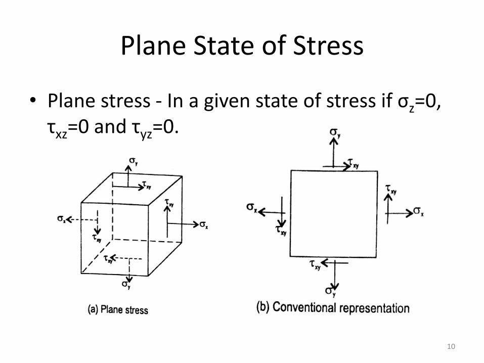
Plane State of Stress
• Plane stress - In a given state of stress if σz=0, τxz=0 and τyz=0.
10

• STRESS ANALYSIS
1. Direct Stress Condition
2. Bi-axial Stress Condition
3. Pure Shear Stress Condition
4. Bi-axial And Shear Stress Condition
11
12
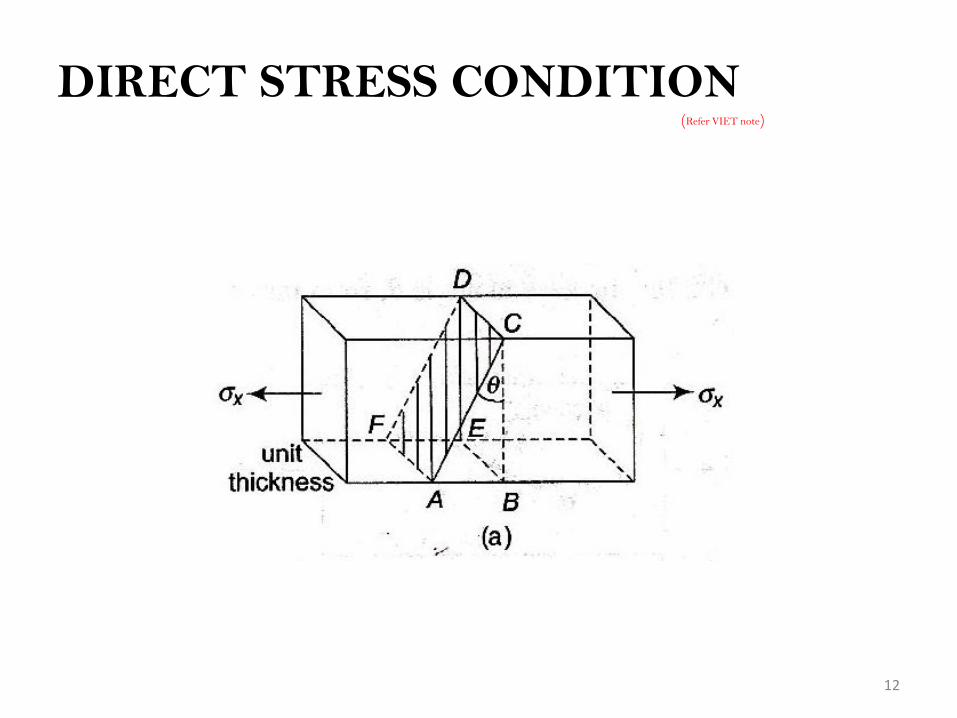
DIRECT STRESS CONDITION(Refer VIET note)

13

14

15

16

17
EQUATIONS OF σƟ and τ Ɵ
1.DIRECT STRESS CONDITION

2. BI-AXIAL STRESS CONDITION
• Let dx, dy and ds be the lengths of sides AB, BC and AC respectively
18

19

20

21

22

23

24

25

EQUATIONS OF σƟ and τ Ɵ
BI-AXIAL STRESS CONDITION
26

27
PURE SHEAR STRESS CONDITION

28

29

30
Equations for
PURE SHEAR STRESS CONDITION

31
BI-AXIAL AND SHEAR STRESS CONDITION

32

33

34

35
Equations for
BI-AXIAL AND SHEAR STRESS CONDITION

36
SUM OF DIRECT STRESSES ON TWO MUTUALLY
PERPENDICULAR PLANES

PRINCIPAL PLANES
AND
PRINCIPAL STRESSES
37

38
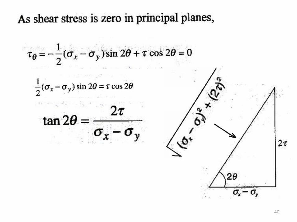
PRINCIPAL PLANES
Planes which have no shear stress. These planes
carry only normal stresses
PRINCIPAL STRESSES
Normal stresses acting on principal planes

39
Larger of two stresses
σ1 – Major principal stress
Smaller
σ2 – Minor Principal stress
Corresponding planes are MAJOR and
MINOR principal planes
40

41

42

43
MAXIMUM (PRINCIPAL) SHEAR STRESSES
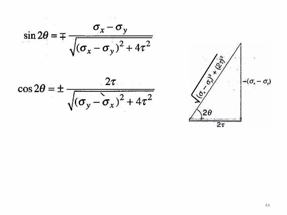
44

45
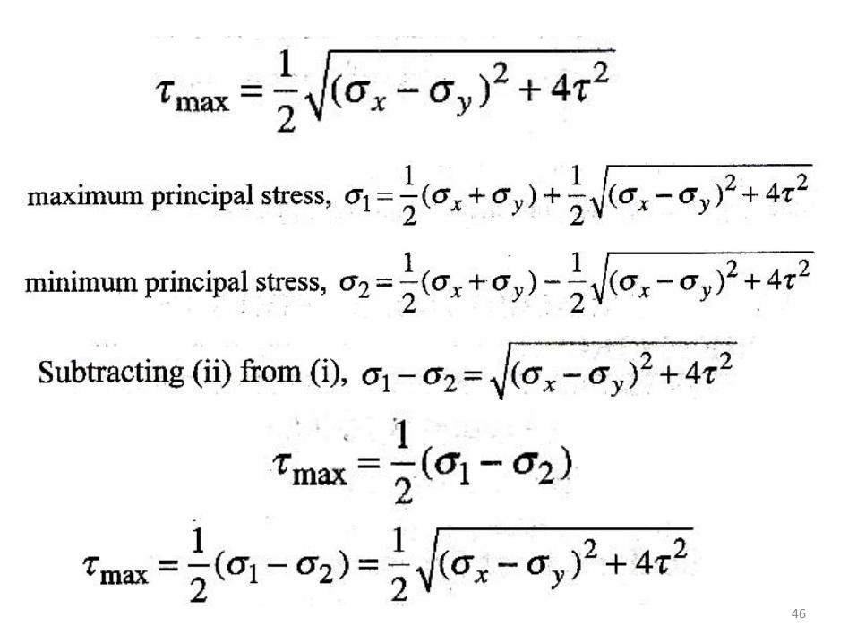
46

47

48
NORMAL STRESS ON THE PLANES OF
MAXIMUM SHEAR STRESS

Mohr’s stress circle
49
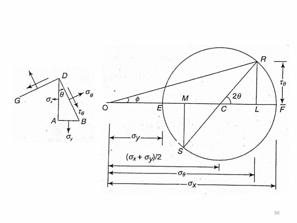
50

51
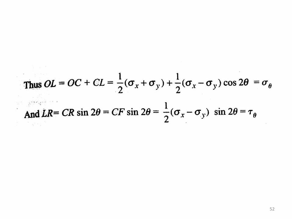
52


Two Direct stresses with simple shear

Principal Stresses

Q). For the stress system shown in the diagram, find the normal and shear stresses acting on the inclined plane using Mohr’s circle method. Also find the resultant stress and its direction


Plane state of strain
• In a plane strain problem εzz = 0, γxz = γyz = 0 and only 3 components of strain εxx , εyy and γxy are enough to describe the state of strain.
• If direct and shear strains along x and y directions are known, normal strain (εθ) and the shear strain (φθ) at angle θ with the x direction of a body can be found.

• Normal Strain
• Analogous to normal stress equation
• Shear strain

Principal Strains
• The maximum and minimum values of strains on any plane at a point are known as the principal strains
• Corresponding planes – Principal planes for strains
• Principal planes are given by

• Principal (Maximum) shear strains
• Planes of maximum shear strains
• Sum of direct strains on 2 mutually perpendicular planes

Principal stresses from Principal strains

• 3D system

Strain Rosette
• Strain in any direction can be measured by using an instrument known as strain gauge.
• In case, directions of principal strains are known, two strain gauges can be used to measure the strains in these directions and by using above equations, the principal stresses can be calculated.
• However, many times the directions of the principal strains are not known. • In such cases, a set of three strain gauges, known as a strain rosette, can
be used to find the strain in three known directions in order to determine stress condition at a point under consideration.
• Let εx and εy be the linear strains in x- and y-directions and φ be the shear strain at the point under consideration.
• Then linear strains in any three arbitrary chosen directions at angles θ1, θ2and θ3 made with the x-axis will be
• If three arbitrary directions are chosen in a set manner and εθ1, εθ2 and εθ3 are measured along these directions, then εx , εy and φ, can be calculated by using the above equations.
• Principal strains and principal stresses can then be calculated.

Rectangular strain Rosette
• If the 3 strain gauges are set at 0˚, 45˚ and 90˚ with the X direction, it is known as rectangular or 45˚ strain rosette.

• Now principal strains and hence principal stresses can be calculated

Equiangular strain Rosette
• If the 3 strain gauges are set at 0˚, 60˚ and 120˚ with the X direction, it is known as equiangular or delta or 60˚ strain rosette.

• Now principal strains and hence principal stresses can be calculated