transition position by chemma methods - cranfield...
TRANSCRIPT
R. & Mo •c. ~014 (8586)
A.R.0. Toc]~c~ Repo~
MINISTRY OF AIRCRAFT PRODUCTION
AERONAUTICAL RESEARCH COMMITTEE REPORTS AND MEMORANDA
Experiments on the Measurement of
Transition Position by Chemma Methods
~y
J. H. PRESTON, B.Sc., PH.D. AND N. E. SWIgETING
W i t h an Appendix by
F. H. BURSTALL~ M.Sc., A.R.I.C.
Crown Copyright Reserved
LONDON: HIS MAJESTY'S STATIONERY OFFICE
Price 2s. 6d. net
..... ES~-ABLtSH~IEt~
g|BRAR
Experiments on the Position by
Measurement of
Chemical Methods
j. H. PRESTON, B.Sc., PH.D. AND N. E. SWEETINO,
OF THE AERODYNAMICS DIVISION, N.P.L.
(W~T. AN AVPENDIX BY F. H. BVRSTA,.L, M.SC., A.R.I.C. o~
Transition
C.a.L.)
Reports a n d M e m o r a n d a No. 2 o r 4
I7th March, 1945.
1. Sumrnary.--(a) Reasons for Enquiry.--The smoke filament technique for detecting transition points is limited to speeds below 180 ft./sec, for orthodox atmospheric tunnels with good lighting and viewing conditions. Also many tunnels are of the enclosed pressure type in which observation is impossible, whilst many atmospheric wind tunnels have poor facilities for lighting and viewing. Hence the need for methods which will supplement the smoke filament technique at high gpeeds, and which can be applied to pressure tunnels and to flight.
(b) Range of Invesl(gation.--The work was almost wholly confined to a particular technique, which consisted in allowing a gas in high concentration to ooze out of an orifice near the nose and flow over the wing surface, which was coated with a suitable sensitive paint, thus producing a stain. Various combinations of gases and paints were tried as suggested by well-known " indicator " tests in chemical analysis. The flow of smoke from the orifice was also studied.
(C) Conclusions.--With suitable choice of gas and paint the transition position can be determined satisfactorily. The controlling factor which decides the definition of the stain in the laminar region is the " threshold " of the paint to the act~ion of the gas. This should be such that only a very faint trace is produced in the turbulent region, whilst an intense and well defined stain occurs in tile laminar region. Care must be taken at moderate Reynolds numbers, when laminar separation is likely to be present. With gas oozing from a hole in the nose only, its presence is likely to pass undetected, but it can be found by introducing the gas near the end of the laminar flow region. For this reason, if facilities for observation exist, it is recommended that the smoke filament technique be used at low wind speeds.
If a permanent or semi-permanent record is desired, then ammoniff in conjunction with mercurous chloride is very good, as also is hydrogen sulphide on white lead, and ammonia on congo-red (an organic pigment). A " fugitive " stain which disappears in about 10 minutes can be produced by passing ammonia over Brom-cresol-purple which has been given a suitable " threshold ". Verysmal l a.mounts of gas are used--from 3 to 6 cubic inches, supplied at a rate of about 1 cubic inch per minute. A rough metering arrangement is desirable.
(d) Further Developments.--" Evaporation " methods are being investigated at the Royal Aircraft Establishment and the National Physical Laboratory. I t is desirable that the technique described in this report should be applied to flow at high speeds and high Reynolds numbers ; if successful, then it can be extended to pressure tunnels and to flight.
(7ags~) A

2
2. I u t r o d u c t i o n . - - T h e part which skin friction plays in the determination o f the drag of aero- dynamic bodies, and the importance of the transition position in this connection seems to have been realised first by B. M. Jones 1 in R. & M. 1199 (1928). It is worth while quoting his remarks in this connection.
"' Methods of studying the boundary layer, involving the use of very small pitot tubes or hot wire anemometers are well known, but possibly very much simpler methods might be devised when the object is merely to find the point at which turbulence develops. Thus, a minute vane or thread carried on a very thin wire might be observed telescopically from outside the tunnel, but there would of course be a danger that the vane itself would break up the laminar layer, which must obviously be in a very critical state for some distance in front of the break-up point.
An alternative method, which might be successful, would be to exude a very small amount of dense smoke from a hole in the nose, or from some other point on the body forward of the break-up point. If the velocity of projection of this smoke were very small it should be unable to escape through the laminar layer, and be spread in a thin film over the solid surface as far back as the point where the boundary layer becomes turbulent ; it should then be immediately dissipated. The difficulty might be in introducing sufficient smoke to be visible without disturbing the layer ; but I believe that if a sufficiently dense smoke was used and a sufficiently bright light was Concentrated at the point where breakdown is expected, and if the observer looked tangentially to the solid surface at right angles to the direction of the flow, the point of breakdown might be rendered visible by a very small quant i ty of smoke. If this were introduced well forward in the body, where the layer is relatively stable, it might be insufficient to disturb the layer appreciably.
Whatever method is finally adopted it is clear that some simple and rapid method of identifying the turbulence point is required, not only to confirm the conjectures of Part I but to facilitate wind tunnel experiments in general. For it will, if the contentions of Part I are accepted, be a matter of supreme importance to know the state of the boundary layer in every experiment upon low resistance shapes.
At the Reynolds numbers of aeroplane flight the drag due to the laminar layer is little more than one-tenth that of the turbulent layer, hence the examination of possible methods of delaying the break-up of the layer, becomes a matter of practical, as well as theoretical, importance. A means of doing this might possibly be to suck the layer away through the surface of the body as fast as it is formed, and so prevent it exceeding the thickness at which turbulence ar ises."--From pages 10 and 11 of Reference 1.
If these remarks applied in 1928, it is evident that they apply much more strongly to-day, since, in addition to the drag, control characteristics are affected bv transition movements. So far as the authors can discover no at tempt appears to have been made to put B. M. Jones' suggested methods into operation before 1939. Reasons would appear to be that existing tunnels were so turbulent that extensive transition regions existed, making the determination of the break-up point impossible ; also, it is only recently that a sufficiently dense non-toxic smoke, free from solid deposits, has been made availabIe.
In 1939, Fage 2, ~ and one of the present authors, during-experiments on a long cylindrical body in the water tunnel, used a technique for measuring transition points which in principle was the same as that suggested by B. M. Jones. 1 Coloured ink was allowed to ooze slowly out of a hole near the nose of the cylinder. The ink was drawn out into a dense parallel filament where the flow was laminar. At the transition point it diffused so rapidly as to be almost invisible in the turbulent boundary layer.
3
In 1941 the present authors 4 succeeded in recording transitions on aerofoils in wind tunnels, using a technique identical with that suggested by B. M. Jones. A fairly dense smoke was obtained by burning rotted wood in a special stove. Troubles were experienced from a tarry deposit which blocked the tube conveying the smoke to the wing or made its way to the exit hole to form a protuberance which caused premature transition. Also the density Was not sufficient for observations at speeds above 70 ft./sec., even with the best lighting and viewing conditions. We found that as the tunnel speed was increased the volume of smoke issuing into the boundary layer had to be cut down.
A search was then begun f o r a denser and more suitable smoke. Eventually, after contacting the Director-General of Scientific Research and Development's Staff, Ministry of Supply, a suitable smoke, which was easily generated, w~s obtained. An apparatus was designed to suit our special requirements, and it is described in R. & M. 20235. The smoke is almost as good as one might hope to obtain. It was originally generated from a high grade lubricating oil, but experience at the N . P L . and the R.A.E. has shown that ordinary paraffin is nearly as good, and the life of the generating apparatus is very greatly prolonged. With the best lighting and viewing conditions the smoke has been used for transition measurements up to 180 ft./sec. At these speeds the filament is exceedingly thin and weak. This is due to the minute flow of smoke, which is small compared with that at low speeds. This low rate of flow has two bad effects on the visual properties of the filament. Firstly, its speed of flow through the pipe probably approaches its rate of fall in still air, and many more drops of oil which comprise the smoke are caught up in the wall. of the pipe, thus reducing the density of the issuing smoke. Secondly, a low rate of flow means a very thin filament, consequently its opacity is reduced. The impression has been gained that it is a speed effect rather than a Reynolds number effect which sets~ a limit to the use of smoke for transition determinations. For instance, in the 13 ft. × 9 ft. tunnel at 150 ft./sec, the Reynolds number of the laminar layer at transition as determined by smoke was 3.0 × 10⁶, whereas in the High-Speed Tunnel, transition could only be determined by smoke at the lowest speed which was of the same order, and the Reynolds number was below 106. Location of the hole or altering its shape does not materially extend the speed above which observation becomes impossible.,
Very fine silk threads have also been observed in the manner suggested by B. M. Jones, with varying success. I t is evident that where oscillations occur 'in the laminar layer the threads will give a false position of the transition point. They are also rather difficult to at tach to the wing, and occasionally stick to the surface. They are of much greater use in detecting regions where separation is present. The real objection to their use for transition work. is that they are not diffusible matter, and the essential property of a turbulent stream is its power of diffusion.
An ingenious method of obtaining the transition point has been developed by Gray 6, who has applied it to transition determinations in flight. The wing was carefully painted with a suitable sensitive paint, and the aircraft was flown through a cloud of gas, which would act chemically on the paint. In the turbulent part of the boundary layer, the gas is much more quickly brought into contact with the paint, than it is in the laminar region. The inter-action of the gas and the paint gives rise to a change of colour, which is sufficiently permanent to last until the aircraft has landed and a record can be obtained. The great advantage of this method is that the transition line for the complete wing---~upper and lower surfaces--is obtained in the one flight. The disadvantages are that at present the painted surface has to be renewed for each test and so the finishes may vary, so that, for instance, movement of transition with speed may be masked; also there is the difficulty of producing a cloud of gas in the atmosphere of sufficient concen- tration, without at the same time making the air turbulent.
3. Alternative to Smoke Filament Technique.--The experiments described below are really an extension of, or a supplement to, the smoke filament technique. The basic idea is still the same as that put forward by B. M. Jones. 1 Instead of smoke, an active gas of high concentration is metered out through a small hole in the nose of the aerofoil at such a slow rate of flow that no disturbances occur. A strip or strips of the wing are painted with a sensitive paint and the gas is allowed to flow until such time that a well defined stain, narrow in width, is produced in the

4
laminar part of the boundary layer. In the turbulent boundary layer a widespread weak stain will be produced or possibly no stain at all if the paint has a "threshold ". In the past, the method has been used to obtain the separation; for instance, Parsons and Walker v used sulphuretted hydrogen on white lead paint for this purpose.
Mr. Burstall of the Chemical Research Laboratory has been responsible for the preparation of suitable paints and his notes are given in the Appendix.
(a) The Test A ere foil and Smoke Observations.--The aerofoil was an early type originally made for the 7-ft. tunnels but never tested. It was cut short so as to span the 4-ft. No. 2 tunnel and set at 0 deg. The fore part of the aerofoil was elliptical up to 2/3c, faired off by an approximately straight tail. The thickness chord ratio was 20 per cent. with the maximum thickness occurring at 0-375c from the leading edge. The actual chord was 2 ft., so a considerable extent of laminar flow could be expected. Stainless steel tubing 1/20 in. internal bore was inserted through the lower surface normal to the chord at 0. lc from the leading edge and the end carefully faired into the upper surface. Similar tubes were inserted later at positions near the transition point.
Preliminary observations of transitions at speeds between 20 ft./sec, and 80 ft./sec, were made. At 20 ft./sec, the flow laminar up to 0-625 of the chord where a fairly strong laminar separation occurred with a separated region occupying 0.1 of the chord. At 40 ft./sec, the separation occurred at the same position, but the separated region shrank to about 0.04c. At 60 ft./sec there were very weak traces of separation, and tile flow at this position was very like that when a transition to turbulent flow takes place at a point. At 80 ft./sec, occasional transitions occurred over an extensive region ahead of the previous separation point, though on the average one would be inclined to say that the flow was laminar. The cause of these transitions was attributed to turbulence in the funnel stream, which, at R = 106, was evidently not low enough to maintain steady laminar flow.
(b) Flow at the Exi t Orifice.--Smoke from an oil-smoke generator was exuded from the orifice at different rates in a wind of 40 ff./sec. The smoke was observed against a dark ground under intense grazing light.
At very small rates of flow the smoke left the orifice to form a thin dense flat band or film downstream of the hole, which continued to the transition point. (See Figure 2 (a).) On increasing the flow of smoke, it took on the appearance of a half body of revolution of about the same width as before, but considerably thicker as shown in Figure 2 (b). Distinct tremors were observed two or three diameters downstream of the hole. A further slight increase in the flow of smoke resulted in the formation of a pear-shaped region of dense smoke downstream of the orifice, at the tail of which turbulent flow set in, completely dispersing the smoke. This is shown in Figure 2 (c). High rates of flow result in the smoke forming a distinct jet, which is bent into the direction of the main stream as it passes through the aerofoil boundary layer. This is shown in Figure 2 (d). The jet is, of course, a turbulent one. The only regime of flow of smoke--or chemical gas--which can be used in transition measurements is the first one which is associated with extremely low rates of flow. Smoke can be controlled visually, but for a gas, some arrangement must be made for metering the flow--at least roughly. The gases most frequently used in the tests to be described were ammonia and hydrogen sulphide. In the case of the former, this was regulated by a burette filled with water, which slowly displaced the air in a vessel, causing it slowly to bubble through a strong aqueous solution of ammonia, and so to the wing. In the case of the hydrogen sulphide this was obtained from a Kipp apparatus and its rate of flow was gauged by the rate it bubbled through.
(c) Tests with Ammonia on Mercurous Chloride.--Mercurous chloride was mixed with water and a little glycerol to form a thin paste. A strip of the wing in line with the orifice was painted with this mixture, care being taken to keep tile surface as smooth as possible. Ammonia-laden air was then exuded from the nose orifice at a rate of about 1 cu. in. per min. for about 3 minutes, or until a sufficiently intense stain had been obtained. At 80 ft./sec, the stain took much longer

5
to develop to its maximum length and which, even after a 6 minutes' run, was weak and tapered towards the end. Photographs of these stains are shown in Figures 1 (a) to 1 (d). The resulting pictures are very similar to the photographs of smoke filaments with colours reversed. These stains bear out the results obtained by smoke and an additional check has also been obtained on a semi-low drag wing in the 7 ft. No. 2 tunnel. I t also works at speeds up to 180 ft./sec. in the 13 ft. × 9 ft. tunnel.
A serious defect in the technique is apparent when a hole at the nose only is used. No indication of the separated flow which is present at the low speeds is given, other than minor distortions of the end of the trace. By inserting other gas inlet tubes behind the main stain, and allowing ammonia to ooze out, stains are developed in the direction of the local flow at the surface. In this way the separation point and extent of the separation region can be mapped. These stains are shown in Figures 1 (a) to 1 (c). The short stain in Figure 1 (c) at 60 ft./sec, is interesting and may at first sight be misleading. I t is in the turbulent part of the boundary layer, and obviously though the gas which is issuing in high concentration is rapidly diffused it must leave a stain in the downstream vicinity of tt~e hole. I t is the form of this stain which decides whether the flow is turbulent. In this case it is a broad pear-shaped stain. A stain in the laminar part of the boundary layer spreads at a much smaller angle and extends to the tran- sition point.
The intensi ty of the stains diminishes with time, but a good enough record for visual purposes remains after 24 hours have elapsed.
(d) Tests with Hydroger~ Sulphide or~ Lead Carbonate a~d or~ Lead Acetate.--In the first tests lead carbonate was mixed with water and a little glycerol to form a paste, which was painted on the wing. In later tests it was mixed with aqueous acetone and sprayed on the wing. Hydrogen sulphide from a small Kipp apparatus was slowly bubbled through at approximately the same rate as the ammonia in the tests above. I t was immediately apparent that the action was much quicker than in the'case of the tests described above in (c). About 1 cu. in. of hydrogen sulphide sufficed to produce a stain which could be photographed. Considerable spread was observed near the separation position, and faint traces showed in the turbulent part of the boundary layer, also the stain in the laminar part of the boundary layer was not quite so clear- cut as those described above in (c) and shown in Figure 1. These features were evidently due to the much lower "threshold " obtaining in the action of sulphuretted hydrogen on white lead. Two typical photographs are shown in Figures 2 (c) and 2 (d) for comparisons with Figures 1 (c) and 1 (d). Tile influence of the occasional transitions at 80 ft./sec, in producing a graded or somewhat indeterminate stain in the centre of the section can be seen, and confirms the visual observations.
similar results were obtained with alcoholic lead acetate, containing a little glycerol which formed a clear varnish on the wing. A very thin smootb coat can be obtained with this mixture. The objection to its use is that the background is too poor for the results to be photographed.
With both of these " paints " the stain is permanent for all practical purposes.
(e) Ammonia and Brom-eresol-purple.--Brom-cresol-purple was mixed with t i tanium white, aqueous acetone and glycerol to form a paste which was painted on to the wing. Tests were made at 40 ft./sec, and 60 ft./sec. Presence of ammonia, oven in very small concentrations, shows up as a fugitive purple stain. When the ammonia was introduced into the boundary layer at even very slow rates of flow a deep purple widespread stain was formed in the laminar region, the edges of which were not sharply defined, whilst a stain of considerable intensity was produced in the turbulent part of tile layer. Without prior knowledge of the transition position it would have been difficult to fix its position by this method. When the flow of ammonia was stopped, the stain cleared itself in 2 or 3 minutes with the tunnel running, that in the turbulent layer vanishing first. I t is evident hat this paint had a low threshold value m relation to tile action of'~kmmonia, and that in the laminar layer, molecular diffusion (coupled possibly with disturbances in the boundary layer arising from the turbulence present in the tunnel stream) was sufficient to produce a concentration of ammonia over a wide band which would react on the paint.

In the next set of tests a proportion of phosphoric acid was added to the brom-cresol-purple mixture composing the paint in order to produce a " threshold " An excellent well-defined stain was obtained in the laminar region, with a faint stain in the turl~ulent region. The transition position was clearly shown. The trace was not permanent and disappeared in about 10 minutes with the tunnel running. The general appearance of the stain, apart from colour, was very similar to that produced by sulphuretted hydrogen on white lead. Diethylamine was also tried as the active gas instead of ammonia. The results were the same.
(f) Ammonia on Congo-red.--Congo-red, an organic pigment, was prepared as a paste with the addition of acid, which turns it blue. A strip of the wing was painted, the tunnel was run, and ammonia was injected into the boundary layer in the usual way. In the laminar part a well-defined red stain quickly developed, which contrasts well with the btue ground, though it was possibly not so good as the methods of (c) and (d) for photographic records.
(g) Chlorine on Starch-iodide.--These are the components employed 'by Gray 6 in the flight tests. The starch-iodide compound was painted on the surface in the usual manner. The resulting stain when chlorine was admitted to the boundary layer was very disappointing.
(h) Drying Tes t s . - - I t was noted in test (c) when the lead carbonate was painted on to the surface as a wet paste, that it dried more rapidly in the turbulent part than in the laminar part of the boundary layer. Under intense reflected light the line of transition could be seen quite clearly
A thin paste of amorphous silica mixed with paraffin was then painted on to the wing. When wet this was almost colourless. The tunnel was then quickly run up to 60 ft./sec. The mixture quickly dried in the turbulent region of flow, turning white. It was also noted that around the leading edge drying also proceeded at a rapid rate. This must evidefitly have been due to the very thin boundary layer as the flow there is laminar. Evidently when transition points are near the nose the method may fail. This has been noticed by Richards in similar tests in the 13 ft. × 9 ft. tunnel.
4. Conclusions--At moderate Reynolds numbers and where conditions permit, it is recom- mended that the smoke filament techn.ique be used. A complete visual picture of the flow is obtained and laminar separation phenomena are immediately apparent.
When the smoke filament technique fails or its use is impossible, t h e n transition positions can be obtained by maintaining a slow flow of a suitable gas in high concentration from a hole in the nose of the wing for a limited period. In its progress over the wing, the gas acts on a sensitive paint, which it stains more or less permanently as desired ; the intensity and the form of the stain depends on whether the boundary layer flow is laminar or turbulent and on the " threshold value " of the paint. The amount of " threshold " should be such that a well-defined intense stain in the laminar part of the boundary layer is obtained and only a very weak stain occurs in the turbulent part. If laminar separation is suspected and suitably disposed holes are available, then the extent of it can be mapped by the same technique.
If the paint can be smoothly applied and the gas flow can be kept low, then the present technique would appear to have very wide applications. The method, for instance, could be applied to flight by having a number of holes in line covering a fairly broad strip of paint. One hole would then be used for each speed and the extent of the stains could be measured on the ground. A similar method could be adopted in pressure tunnels and a definite quanti ty of gas could be metered in turn to each hole, which would be allocated to a particular, incidence or Reynolds number. On the other hand, if a stain is produced only in the laminar part, one could start the experiment with transition close to the nose and allow the stain to develop downstream as conditions were varied and photographically record each position in turn. The method is not limited to aeronautical applications.

The " drying " or evaporation methods being developed at the R.A.E. and by Richards at the" N.P.L. have the advantage that the transition " line " for the complete wing is obtained, but their use is restricted to atmospheric or easily accessible tunnels. Also the method may fail near the nose.
Gray's method 6 has the same advantage, but would appear to be restricted to flight, as the presence of toxic gas, even in small quantities in wind tunnels is not likely to be popular with the operators.
I t is, therefore, seen that a wide choice of fairly simple methods of the type originally suggested by B. M. Jones are available. Further experience is certainly desirable with all of them, par- ticularly at high speeds and high Reynolds numbers. Since this report was written, tests in the 13 ft. × 9 ft. N.P.L. wind tunnel have shown that hydrogen sulphide emitted from pressure orifices 0.02 in. dia. over lead carbonate paint enables transition to be determined at a wind speefl of 210 ft./sec. Also laminar separation regions can be satisfactorily explored.
5 . A c k n o w l e d g m e n t . - - M i s s Emms took the photographs reproduced in this report.
REFERENCES
1. B.M. Jones . . . . . . . . . . . . Skin Friction and the Drag of Streamline Bodies. R. & M. 1199. (1928.)
2. A. Fage and J. H. Preston . . . . . . . . Description of a Water Tunnel and Apparatus for the " Investigation of Flow Problems. Jour. Roy. Aero. Soc.
April, 1941.
3. A. Fage and J. H. Preston. . .
4. J . H . Preston and N. E. Sweeting
S. J H. Preston and N. E. Sweeting
6. W . E . Gray . . . . . .
7. J . F . Parsons and J. A. Walker
. . On Transition from Laminar to Turbulent Flow in the Boundary Layer. Proc. Roy. Soc. A.178. 1941.
Wood Smoke as a Means of Visualising Boundary Layer Flow at High Reynolds Numbers. Jour. Roy. Aero. Soc. March, 1943. No. 387. XLVII.
An Improved Smoke Generator for Use in the Visualisation of Air Flow, particularly Boundary Layer Flow at High Reynolds Numbers. R. & M. 2023. October, 1943.
A Chemical Method of Indicating Transition in the Boundar.y Layer. A.R.C. 8034, Ae. 2608. R.A.E. Tech. Note Aero. 1466. July, 1944. (To be published.)
An Investigation of the Phenomenom of Separation in the Air Flow around Simple Quadric Cylinders. N.A.C.A. T.N. 354. 1930.
8
APPENDIX
By F. H. Burstall, M.Sc., A.R.I.C., of the Chemical Research Laboratory.
From the chemical standpoint there is a very wide range of chemical reactions which could be used for indicating transition position ; accordingly the chemical preparations described in this paper should be regarded as of a preliminary nature designed primarily to test the possibilities of the method. The reactions selected may be broadly divided into (a) metallic salts such as mercurous chloride and lead carbonate, which yield characteristic stains with ammonia and hydrogen sulphide respectively, (b) organic indicators used in volumetric chemical analyses represented by brom-cresol-purple and congo-red, which manifest reversible colour change under suitable conditions in acid or alkaline medium, (c) physical processes depending on evaporation. It seems reasonable to suppose that these and other methods will each find appropriate use depending on the nature of the experimental conditions.
(a) Me~,curous Chloride--Paste.--Freshly prepared mercurous chloride (10 gins.) was ground to a paste with water (10 m.1.) and glycerol (0.5 m.1.).
Spray.--A suitable spray can be prepared from the foregoing paste b y addition of acetone (or alcohol) (50 m.1.). Mercurous chloride gave black to grey colours with ammonia due to separation of mercury with concurrent formation of ~nercuric chloride.
Lead Carbonale--Paste.--Lead carbonate (10 gms.) was ground to a paste with water (5 m.1.) and glycerol (0.5 m.1.).
Spray.--Dilution of the above paste with acetone (10 m.1.) gave a suitable mixture ; larger quantities were made up in proportion. These preparations gave black to brown lead sulphide with hydrogen sulphide.
Lead Acetate--Solution.--Lead acetate (Pb (C2HaOe) 2 3H20, 5 gins.) in water (10 m.1.), alcohol (50 m.t.) and glycerol (1 m.1.).
Chloriue aud Starch-iodide--Paste.--Titanium white (10 gms.) was made into a paste v~ith 10 m.1. of a solution containing potassium iodide (0.5 g.), starch (1 m.1. of a 1 per cent. aqueous solution), glycerol (0.5m.1.) and sodium thiosulphate (1 m.l. of a 0.1 N solution). This mixture gave disappointing results with chlorine, a fact which may be traced to the nature of the experimental technique which differed considerably from that used by Gray in his experiments.
(b) Brom-cresol-purple--Paste.--A mixture containing t i tanium white (10 gms.), brom-cresol- purple (0.1 gin. in alcohol 10 m.1.) water (4 m.1.), 2 N sulphuric acid (1 m.l.) and glycerol (0.5 m.1.) was ground to a paste. This yellow product gave a purple colour with ammonia vapour ; this colour returning to the original yellow on exposure to air. Addition of more acid slowed down the disappearance of the characteristic purple colour.
Spray.--A spray solution was made up containing brom-cresol purple (0.5 gms.), water 50 m.1.), alcohol (50 m.1.), glycerol (3 m.1.), phosphoric acid (0.5 m.1. of acid d. 1.75), and alumina (15 gms.). Alumina was used to replace t i tanium white, which was temporarily out of supply ; the latter oxide was more suitable for these pastes and sprays.

9
Congo-red--Paste.--A mixtuce was prepared consisting of congo-red (0.1 g. in alcohol 10 m.1.), water (5 m.1.), 2 N sulphuric acid (1 m.l.), glycerol (0.5 m.l.), and titanimn white (10 gms.). This product, which was blue in colour, became red with ammonia. Exposure to mineral acid vapours caused a return to the original blue tint, but carbon dioxide in air was not sufficiently acidic to promote this change.
(c) Physical Methods--Amorphous Silica and Paraffin.--Finely divided amorphous silica (10 gins.) was made into an almost transparent jelly by grinding with paraffin oil (b.p. 150-250 ° C. 40 m.1.) ; evaporation of solvent then leaves a white deposit of the silica. The principle of the method is to be found in the fact that the refractive indices of amorphous silica and paraffin oil are very similar; accordingly, a suspension of the former in the latter appears substantially transparent. Refinements of this process operating with purer organic liquids of suitable vapour pressures should provide more satisfactory results, though objections to methods depending on comparative processes (see § 4) will remain.
Gases.--Ammonia was generated by bubbling air through a concentrated aqueous solution (d. 0"880) of the gas.
Hydrogen Sulphide was prepared by action of hydrochloric acid (1 vol. concentrated acid, 1 vol. water) on ferrous sulphide.
Chlorine was obtained by the action of hydrochloric acid on manganese dioxide or potassium permanganate, air being bubbled through the warmed mixture.
Ethylamine.--Air was bubbled through the anhydrous base.
B
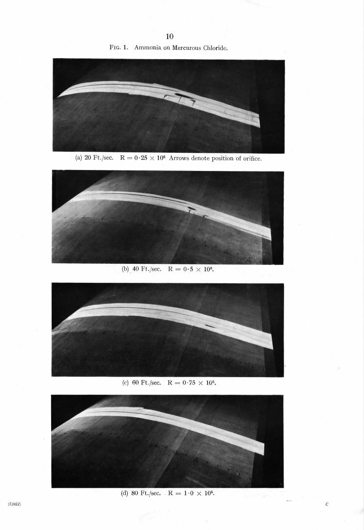
10 FIG. 1. A m m o n i a on Mercurous Chloride.
(a) 20 Ft . / sec . R = 0 . 2 5 × 10" Arrows dcm)te pos i t ion of oriticc.
(1)) 40 Ft.,:sec. R = 0 . 5 x 10';.
(c) 60 Ft . /sec . R = 0 .75 × 10%
(d) 80 Ft . / sec . R = 1 "0 × 10 ~.
(7a9~1) C

i l
FiG. 2. Flow of Smoke from Orifice.
Elevml=;on
>) Vlr~q 5io~, F'loiv
(b) ,,Slow Flow
(¢) Mediun'l IRo~
td) 5~-¢~q FIo~#
Pla~
t l ~ e D ~ - ~ - - ~ " ' " ~ .....
FIG. 3. Hydrogen Sulphide on Lead Carbonate (White Lead).
(c) 60 Ft./scc.
(78951) Wt. 9/7116 7/46 Hw. G.377/1
(d) 80 Ft./sec.
I
Publications of the t
Aeronautical Research Committee T E C H N I C A L REPORTS OF T H E A E R O N A U T I C A L
RESEARCH C O M M I T T E E - - i934-}5 Vol. I. Aerodynamics. 4os. (4os. 8d.)
t
I Vol. II. Seaplanes, Structures, Engines, Materials I etc. 4os. (4os. 8d.)
X935-~6 Vol. I. Aerodynamics. 3os. (3os. 7d.) Vol. II. Structures, Flutter, Engines, Seaplanes, etc.
3os. (3os. 7,/.) 1936 Vol. L Aerodynamics General , Performance,
Airscrews, Flutter and Spinning. 4os. (4os. 9d.)
Vol. II. Stability and Control, Structures, Seaplanes, Engines, etc. 5os. (5os. Iod.)
x937 Vol. L Aerodynamics General , Performance, Airscrews, Flutter and Spinning. 4os. (4os. 9d.)
Vol. II. Stability and Control, Structures, Seaplanes, Engines, etc. 6os. (61s.)
A N N U A L REPORTS OF T H E A E R O N A U T I C A L RESEARCH 0 C O M M I T T E E w
I933-34 xs. 6d. (xs. 8do) I934-35 Is. 6d. (Is. 8d.)
April 1, I935 to December 3 I, 7936. 4 s, (4 s. 4d.) I937 2s. (2s. 2d.) I938 IS. 6d. (IS. 8d.)
INDEXES TO T H E T E C H N I C A L REPORTS OF T H E ADVISORY C O M M I T T E E ON A E R O N A U T I C S - -
December I, I 9 3 6 - - J u n e 3 o, 3939 Reports & Memoranda No. I85o. Is. 3 d. (Is. 5d.)
July I, ~939- -June 3 o, I94. 5 Reports & Memoranda No. I95o. IS. (Is. 2d.)
Prices in ~rackets include postage.
Obtainable from o ¢J
His Majesty's Stauonery Ofiqce London W.C.e : York House, Kingsway
[Post Orders--P.O. Box No. 569, London, 8.E.I.] Edinburgh 2: I3A Castle Street Manchester a: 39-4 x King Street Cardiff: I St. Andrew's Crescent Belfast: 80 Chichester Street
or through any bookseller.
S.O. Code No. "a3--'~ox4