translating a typical business process modelling language ... · translating a typical business...
TRANSCRIPT
Translating a Typical Business Process Modelling Language to a Web
Services Ontology through Lightweight Mapping
Gayathri Nadarajan1 Yun-Heh Chen-Burger2
Centre for Intelligent Systems and their Applications (CISA)
School of Informatics, University of Edinburgh
Appleton Tower, Crichton St, Edinburgh EH8 9LE, Scotland1 Email: [email protected]
http://homepages.inf.ed.ac.uk/s0450937/2 Email: [email protected]
http://www.aiai.ed.ac.uk/˜jessicac/
Abstract: Bridging the gap between Enterprise Modelling methods and Semantic Web services is an importantyet challenging task. For organisations with business goals, the automation of business processes as Web servicesis increasingly important, especially with many business transactions taking place within the Web today. Takingone approach to address this problem, a lightweight mapping between Fundamental Business Process ModellingLanguage (FBPML) and the Web Services Ontology (OWL-S) is outlined. The framework entails a data modeltranslation and a process model translation via the use of ontologies and mapping principles. Several workingexamples of the process model translations are presented together with an implementation of an automated trans-lator. FBPML constructs and process models that could not be translated to OWL-S equivalents highlight thedifferences between the languages of the two domains. It also implies that evolving Semantic Web technologies, inparticular OWL-S, are not adequate for all service modelling needs and could thus benefit from the more tradi-tional and mature BPM methods. On a more interesting note, this is effectively the first step towards enabling asemantic-based business workflow system.Keywords: Enterprise Modelling, Business Process Modelling Methods, Semantic Web Services, FBPML, OWL-S,Ontologies, Lightweight Mapping.
1 Introduction
The need for more sophisticated Web-based support tools has become apparent with the fast advancement of theWeb and the Semantic Web vision [5]. Business-to-Business (B2B) Electronic Commerce is fast becoming themost important application area of Semantic Web technology in terms of market volume [2]. Enterprise Modelling(EM) methods, on the other hand, are mature, established procedures that are commonly used as analysis tools fordescribing and redesigning businesses by entrepreneurs. They have been well recognised for their value in providinga more organised way to describe complex, informal domain [8].
The existence of established EM methods, such as Business Process Modelling (BPM) methods, suggests that
1
they could be exploited by emerging technologies such as Semantic Web services to provide a more mature frame-work incorporating both business- and Web application-specific technologies. In a wider context this aims to bringbusiness-oriented and technical-oriented communities closer in order to achieve common organisational goals.
To this end, several efforts have emerged to bridge the gap between EM methods and Semantic Web services.The notion of Semantic Business Process Management (SBPM) [13] was proposed to utilise semantic capabilitieswithin business process technologies in one consolidated technology. This is motivated by the limited degree ofmechanisation within BPM methods which could be supplemented by Semantic Web services frameworks. Thiseffort complements the work presented by this paper. It also indicates an increasing interest in combining SemanticWeb technologies with EM methods.
On a lower level, translation between languages could be categorised broadly into heavyweight and lighweightapproaches. Heavyweight mapping takes into account the understanding of the semantics of the notations involvedand provides a formalism for the mapping procedure. This approach is clearly more theoretical, however, recentwork in mapping between BPM and Semantic Web languages have used a more pragmatic approach where identicalor similar language constructs are mapped conceptually. FBPML has been translated to OWL-S in some prelim-inary work [12, 22, 21], BPEL4WS has been mapped to OWL-S [30, 4] and OWL-S has been mapped to WSMO[29]. Some initial work on mapping between ontologies has been carried out in [27], which proposes an abstractmapping language. This paper integrates the principles outlined in these efforts into a lightweight ontologicalconceptual mapping framework.
1.1 Enterprise and Process Modelling
The goal of applying an enterprise modelling method is to seek ways to improve an organisation’s effectiveness,efficiency and profitability. EM methods are typically informal or semi-formal. They provide notations whichenable entrepreneurs to describe aspects of their business operations. The notation is normally complementedwith semi-formal or natural language descriptions which allows details of the business operations to be described.
Many EM methods have emerged to describe and redesign businesses, namely business process modelling,business system modelling and organisational context modelling methods [8]. Business Process Modelling (BPM)methods are able to formally express informally practiced procedures. More importantly, actions and effects ofthese processes can be demonstrated using simulation techniques. Some examples of BPM methods representationsinclude Process Specification Language (PSL) [28], Integration DEFinition Language (IDEF3) [19], extended UML’sActivity Diagram [26] and Petri-Nets [24].
In the course of half a decade ago, new process languages and models have been developed to promote theunderstanding and interoperability of process semantics over the Web, with the extensibility of operating overthe Semantic Web. They are characterised by XML and XML-based languages, such as the Resource DescriptionFramework (RDF) [15] and the Web Ontology Language (OWL). Some of these languages include Business ProcessExecution Language for Web Services (BPEL4WS), Business Process Modelling Language (BPML) [3], Web ServiceOntology (OWL-S) [18], and more recently, Web Services Modelling Ontology (WSMO) [25].
1.1.1 FBPML
The Fundamental Business Process Modelling Language (FBPML) [9] is an inherited, specialised and combinedversion of several standard modelling languages. In particular, FBPML adapts and merges two established processlanguages; PSL and an IEEE standard, IDEF3. PSL provides formal semantics for process modelling conceptsbut does not provide visual notations or model development methods. IDEF3, on the other hand, provides visualnotations and a rich modelling method, but its semantic is informal. FBPML is slightly adapted to provide a
2
formal representation of IDEF3.The main aim of FBPML is to provide support for virtual organisations which are becoming more and more per-
vasive with the advancement of Web technology and services. It ultimately seeks to provide distributed knowledge-and semantic-based manipulation and collaboration. Most importantly, people with different responsibilities andcapabilities could work together to accomplish tasks and goals without technological or communication barrierscaused by the differences in their roles.
Several characteristics of FBPML make it ideal as the BPM language of choice. It can express business processesin conventional first order predicate logic and has two sections to provide theories and formal representations fordescribing data and processes; the Data Language and the Process Language. It provides an abstraction that isseparated from the actual implementation. Another ideal characteristic of FBPML is that it provides a visualpresentation for the underlying ontology that is not present in most BPM languages. Visual data modellinglanguages may be Entity-Relationship and UML Data Diagram, among others. It also has a notion of time thatmay be synchronised.
FBPML has been applied successfully in several projects and tools, such as Knowledge Based Support Tool forBusiness Models (KBST-BM), Knowledge Based Support Tool for Enterprise Models (KBST-EM)1 and AdvancedKnowledge Technologies (AKT) [1]. However, as with most BPM languages, FBPML could not be used directlywith software systems, including web services.
1.2 Emerging technologies for the Semantic Web
The Semantic Web is a collaborative effort led by the World Wide Web Consortium (W3C)2 with participationfrom a large number of researchers and industrial partners. Since its introduction, the Semantic Web has becomethe buzzword among communities across many related disciplines; from knowledge engineers to human-computerspecialists to business entrepreneurs. It is envisioned to be an extension of the current Web, in which informationis annotated with meaning, so as to provide for better machine-processability and automated reasoning. Suchprovision, ultimately, would enable better cooperation between computers and people [5]. Being a cutting edgeresearch field, some emerging technologies and standards are being developed to realise the Semantic Web. Threekey languages are discussed and considered for the mapping framework.
1.2.1 BPEL4WS
Business Process Execution Language for Web Services (BPEL4WS) [6] is an industrial effort which formalisesthe specification of Web services, their flow composition and execution. By doing so, it extends the Web servicesinteraction model and enables it to support business transactions. It defines an interoperable integration model thatshould facilitate the expansion of automated process integration within corporations and in business-to-businessspaces. BPEL4WS builds on and extends XML and Web services specifications. The BPEL4WS process model islayered on top of several XML specifications, expressed entirely in XML, uses and extends Web Services DescriptionLanguage (WSDL) [10], and uses WSDL and XML Schema to describe its data. However, using a representationsuch as XML Schema is inadequate for describing rich data models as required by Semantic Web services.
1.2.2 WSMO
The Web Services Modelling Ontology (WSMO) [25] provides a conceptual underpinning and a formal languagefor Semantic Web services. It has its conceptual basis in the Web Service Modelling Framework (WSMF) [11],
1KBST-BM and KBST-EM are developed by Artificial Intelligence Applications Institute (AIAI), University of Edinburgh.2http://www.w3.org/
3
refining and extending this framework and developing a formal ontology and set of languages. Its main modellingelements are Ontologies, Goals, Web services and Mediators and is described in the Web Service modelling Language(WSML) [17]. WSMO also has the aim of building editing tools and reference implementation. Current efforts[16, 29, 23] have been focused on comparing and mapping OWL-S to WSMO, with the intention of incorporating thetwo technologies together. Although it promises an improvement to cost-effectiveness, scalability and robustnessof current solutions, its framework is still very much in its early stages of development. Thus it could be prematurefor a concrete and realistic mapping to be performed with this language.
1.2.3 OWL-S
OWL-S [18] is a Web service ontology written in the Web Ontology Language (OWL) [20] extended with theSemantic Web Rule Language (SWRL) [14]. Its main aim is to describe Web services in machine-processableforms. OWL-S markup of Web services facilitates the automation of Web service tasks, including automatedWeb service discovery, execution, composition and interoperation. Following the layered approach to markuplanguage development, the current version of OWL-S builds on OWL, which in turn, is built on top of the ResourceDescription Framework (RDF) [15], which is an XML-based framework that could be used to describe data models.
1.3 Rationale
BPEL4WS, although well accepted, has been primarily developed to execute Web services in that it works morelike a programming language than a knowledge model or a process ontology. Therefore the semantics of processeswritten using BPEL4WS is not well-defined. Thus it does not provide a rich enough representation to supportSemantic Web services as outlined in section 1.2.1. This brings OWL-S and WSMO as the closest competingtechnologies to be considered.
OWL-S has been criticised due to its relative simplicity and incompleteness, which has led to the developmentof WSMO. The conceptual and functional comparisons between the two [16] show that WSMO stands out as amore promising approach with its more extensive framework and support for ontological reuse and flexibility. Italso enables the static and dynamic reuse of Web services to achieve the functionality of a more complex service.However, OWL-S is more mature in some aspects such as process model definition and the grounding of Webservices since it has been under development for a longer time. Moreover, it has a distinct data and process modelwhich makes it semantically richer and structurally similar to FBPML that allows for an appropriate mappingprocedure to be carried out as will be outlined in the following sections. Therefore, although WSMO seems to beconceptually stronger than OWL-S, it has yet to further define some open aspects in order to be completely usablein real applications.
2 Lightweight Ontological Mapping Framework
A conceptual mapping framework was devised to translate FBPML to OWL-S, motivated by the fact that bothlanguages have a clear separation between their data and process schemas. FBPML’s data model is described in theFBPML Data Language while OWL-S is described in OWL and SWRL. FBPML’s process model is described bythe FBPML Process Language (FBPML PL), while OWL-S contains its own classes to describe its process model.Thus the mapping framework has been divided into a data model component and a process model component.The two clearly defined mapping parts constitute the main essence of this work.
The data and process models of each language are represented using ontologies. The ontology diagrams forFBPML data and process models were based on the Support Ontology from the AKT Project [1]. By using
4
a semantic representation of the data and process models, the translation is conducted with accordance to therespective methodologies outlined in the following sections.
3 Data Model Translation
A data model describes how the relevant facts pertaining to a specific application is organised logically, namelythe concepts, instances, relationships between them and their restrictions. The mapping of data models betweenFBPML and OWL-S involves the translation of representations of concepts (or classes), instances (of the concepts)and the relationships between the concepts and instances from FBPML DL to OWL. It also entails the translationof the restrictions (or constraints) from FBPML DL to OWL.
3.1 FBPML Data Language
The FBPML Data Language (FBPML DL) [7] is first-ordered. The syntactic convention that has been used in Pro-log has been adopted for its representation. The four main parts that constitute FBPML DL are the foundationalmodel, the core data language, the extension data language and the meta-predicates of FBPML. The foundationalmodel includes the use of logic and set theory to represent concepts, primitive predicates and functions (relation-ships) and mathematical theory on the manipulation of integer, rational and real numbers. The core data languageincludes the fundamental predicates and functions that are common to all applications of the language while theextension data language contains predicates and functions that are additional to the core data language. Theyare usually user-defined and are often application and domain-specific. Meta-predicates give definitions for otherpredicates and may define axioms of an application model. The rest of this subsection provide an overveiw of thecomponents of FBPML DL in Prolog syntactic convention where applicable.
Concepts. Concepts in the Foundational Model include the classes of things that could occur in a context or do-main in question. The concepts include numbers (number/1), variables (variable/1), constants (constant/1),lists (list/1), strings (string/1) and terms (term/1).
Functions. Functions in FBPML DL include those that evaluate boolean expressions, such as if a term is anatom (atom/1), atomic (atomic/1), a compound (compound/1) or a list (is list/1). There are functions thatmanipulate logical expressions such as not (not/1) and or (or/1), as well as arithmetic boolean expressions, suchas the symbolic representations of equals (=/2), greater than (>/2), greater than or equals to (>=/2), less than(</2) and less than or equals to (=</2).
Logical Quantification. FBPML provides for full first order logic expressiveness whereby quantification play animportant role in determining the scope of the variables within a statement. Quantification expressions includeforall (forall/1) and exist (exist/1). Constants true (true/0) and false (false/0) also provide for conditionsthat remain always true and false, respectively.Predicates. The core predicates for the data language include classes, subclasses, instances, attributes, properties,constraints and relations; some which have been represented symbolically as functions, such as boolean arithmeticfunctions equal, greater than, less equal and so on. Table 1 contains the main predicates contained within theFBPML Data Language.
Meta-predicates. Meta-predicates define additional predicates to the core data language. Two such predi-cates include def predicate(Pred, Def) and axiom(Conclusion, Hypothesis). Def predicate introduces a
5
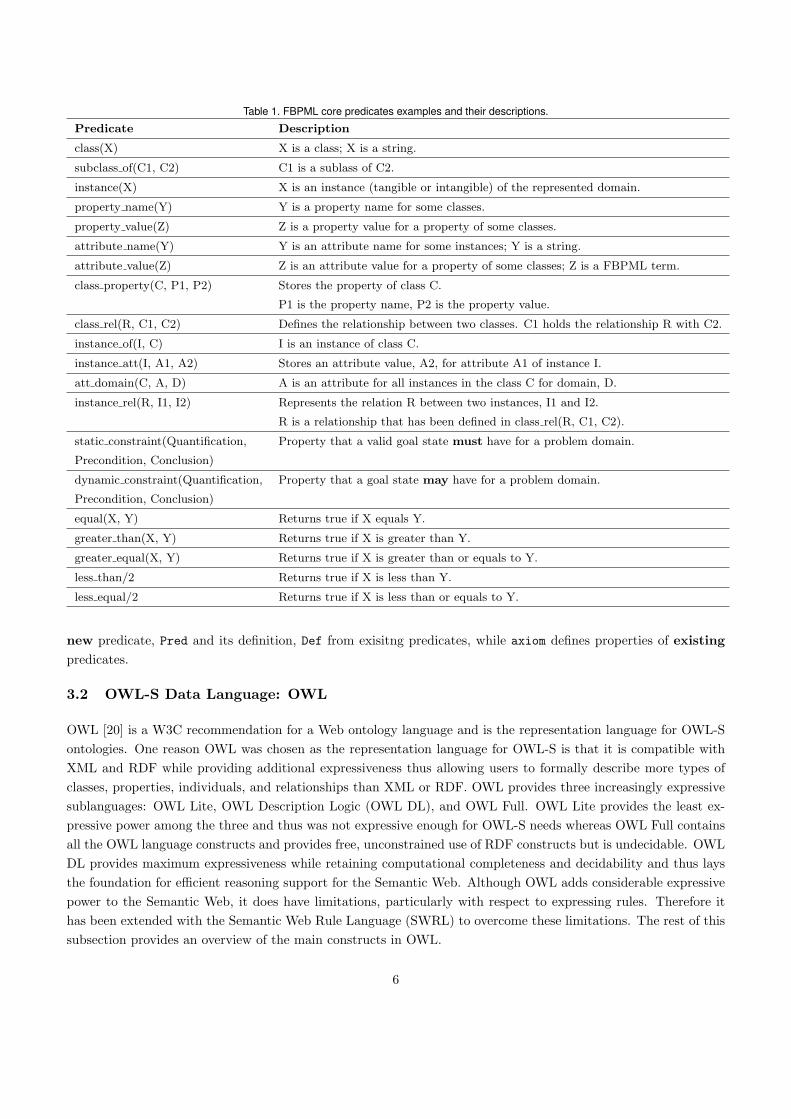
Table 1. FBPML core predicates examples and their descriptions.
Predicate Description
class(X) X is a class; X is a string.
subclass of(C1, C2) C1 is a sublass of C2.
instance(X) X is an instance (tangible or intangible) of the represented domain.
property name(Y) Y is a property name for some classes.
property value(Z) Z is a property value for a property of some classes.
attribute name(Y) Y is an attribute name for some instances; Y is a string.
attribute value(Z) Z is an attribute value for a property of some classes; Z is a FBPML term.
class property(C, P1, P2) Stores the property of class C.
P1 is the property name, P2 is the property value.
class rel(R, C1, C2) Defines the relationship between two classes. C1 holds the relationship R with C2.
instance of(I, C) I is an instance of class C.
instance att(I, A1, A2) Stores an attribute value, A2, for attribute A1 of instance I.
att domain(C, A, D) A is an attribute for all instances in the class C for domain, D.
instance rel(R, I1, I2) Represents the relation R between two instances, I1 and I2.
R is a relationship that has been defined in class rel(R, C1, C2).
static constraint(Quantification, Property that a valid goal state must have for a problem domain.
Precondition, Conclusion)
dynamic constraint(Quantification, Property that a goal state may have for a problem domain.
Precondition, Conclusion)
equal(X, Y) Returns true if X equals Y.
greater than(X, Y) Returns true if X is greater than Y.
greater equal(X, Y) Returns true if X is greater than or equals to Y.
less than/2 Returns true if X is less than Y.
less equal/2 Returns true if X is less than or equals to Y.
new predicate, Pred and its definition, Def from exisitng predicates, while axiom defines properties of existingpredicates.
3.2 OWL-S Data Language: OWL
OWL [20] is a W3C recommendation for a Web ontology language and is the representation language for OWL-Sontologies. One reason OWL was chosen as the representation language for OWL-S is that it is compatible withXML and RDF while providing additional expressiveness thus allowing users to formally describe more types ofclasses, properties, individuals, and relationships than XML or RDF. OWL provides three increasingly expressivesublanguages: OWL Lite, OWL Description Logic (OWL DL), and OWL Full. OWL Lite provides the least ex-pressive power among the three and thus was not expressive enough for OWL-S needs whereas OWL Full containsall the OWL language constructs and provides free, unconstrained use of RDF constructs but is undecidable. OWLDL provides maximum expressiveness while retaining computational completeness and decidability and thus laysthe foundation for efficient reasoning support for the Semantic Web. Although OWL adds considerable expressivepower to the Semantic Web, it does have limitations, particularly with respect to expressing rules. Therefore ithas been extended with the Semantic Web Rule Language (SWRL) to overcome these limitations. The rest of thissubsection provides an overview of the main constructs in OWL.
6
Classes and Instances. Classes are defined using the owl:Class element. There are two predefined classes,owl:Thing, which defines the most general class that contains everything, and owl:Nothing, which is the emptyclass. Hence, every class is a subclass of owl:Thing and a superset of owl:Nothing. Instances, as in FBPML andmany conventional programming languages, are actual occurrences of the classes or objects that in turn representan abstraction for them. The syntax for OWL class and instance could be found in Table 2.
Property Elements and Restrictions. Two kinds of properties are relevant to OWL; object properties and datatype properties. An object property relates (all) instances of a class to (all) instances of another class while a datatype property relates (all) instances of a class to datatype values, such as integers, strings and so on. OWL also ex-presses built-in properties such as transitivity (owl:TransitiveProperty), symmetry (owl:SymmetricProperty)
and inverse (owl:inverseOf). One can specify constraints or restrictions on properties using the rdfs:subClassOfelement. In general, an owl:Restriction element contains an owl:onProperty element and one or more restric-tion declarations.
Quantification and Cardinality Restrictions. The elements owl:allValuesFrom and owl:someValuesFrom
provide for logical universal and existential quantification respectively. However, the notion of quantification withinOWL is still limited and is being extended by other logical formalisms such as SWRL. Cardinality restrictions canalso be expressed using similar conventions for property restrictions, the restriction declaration would containowl:minCardinality and/or owl:maxCardinality elements to define the range of cardinality allowed.
Boolean Combinations. Union, intersection and complement of classes are some binary relations that can beexpressed directly in OWL-S using the constructs owl:unionOf, owl:intersectionOf and owl:complementOf
elements. Other boolean combinations are also possible. For example, if we want to express that ”a is disjointwith b”, the following syntax could be used:<owl:Class rdf:about="#a">
<owl:disjointWith rdf:ID="#b"/>
</owl:Class>
Data types. OWL does not have any predefined data types, but it allows one to use XML Schema’s predefineddata types. Although XML Schema provides for a mechanism to construct user-defined data types, these cannotbe used in OWL. Furthermore, only some of the predefined data types can be used in OWL, such as string,
integer, Boolean, time and date. It could be argued that the use of data types within OWL is still limited.
4 Data Model Mapping
The devised data model translation encompassed the mapping of classes, instances, relationships and restric-tions. The procedure for data model mapping could be summarised in three main steps, refined from [29].(1)Pre-processing (if any), for instance organise modelling constructs into Prolog readable syntax. (2) Mapping ofontologies, the two ontologies in question are provided by Figures 3 and 4. This consists of the following steps.(i) Mapping of classes, which includes the mapping between the concepts (ii) Mapping of instances, which is themapping of the instantiation of the concepts (iii) Mapping of relationships between the classes, instances andattributes and (iv) Mapping of restrictions which entails the mapping of constraints between the data models. (3)Mapping for rules/axioms.
7
The remaining subsections elaborate these steps, provide the mapping using an adaptation of the formal mappinglanguage initiated by [27] and the syntax of the translations between the data models of FBPML and OWL.
4.1 Ontologies of the Data Models
The data model of FBPML and OWL-S are represented semantically using ontology notation, as described byFigure 3 and Figure 4. Applying the mapping principles to the derived ontologies, a class in FBPML is mappedto a class in OWL-S, an instance of a class in FBPML is mapped to an instance of a class in OWL-S and arelationship in FBPML is mapped to a relationship in OWL-S. The following subsection provides the formalismfor the mapping and the translated syntax from FBPML DL to OWL.
4.2 Mapping of Classes and Instances
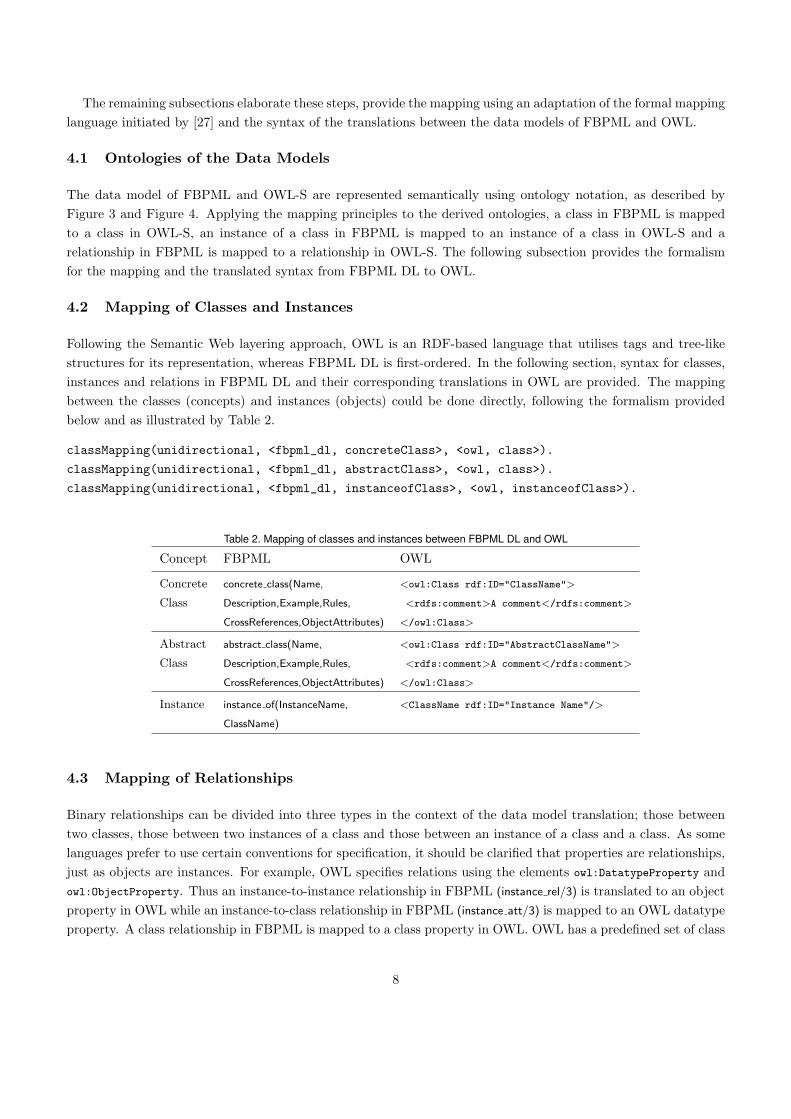
Following the Semantic Web layering approach, OWL is an RDF-based language that utilises tags and tree-likestructures for its representation, whereas FBPML DL is first-ordered. In the following section, syntax for classes,instances and relations in FBPML DL and their corresponding translations in OWL are provided. The mappingbetween the classes (concepts) and instances (objects) could be done directly, following the formalism providedbelow and as illustrated by Table 2.
classMapping(unidirectional, <fbpml_dl, concreteClass>, <owl, class>).
classMapping(unidirectional, <fbpml_dl, abstractClass>, <owl, class>).
classMapping(unidirectional, <fbpml_dl, instanceofClass>, <owl, instanceofClass>).
Table 2. Mapping of classes and instances between FBPML DL and OWL
Concept FBPML OWL
Concrete concrete class(Name, <owl:Class rdf:ID="ClassName">
Class Description,Example,Rules, <rdfs:comment>A comment</rdfs:comment>
CrossReferences,ObjectAttributes) </owl:Class>
Abstract abstract class(Name, <owl:Class rdf:ID="AbstractClassName">
Class Description,Example,Rules, <rdfs:comment>A comment</rdfs:comment>
CrossReferences,ObjectAttributes) </owl:Class>
Instance instance of(InstanceName, <ClassName rdf:ID="Instance Name"/>
ClassName)
4.3 Mapping of Relationships
Binary relationships can be divided into three types in the context of the data model translation; those betweentwo classes, those between two instances of a class and those between an instance of a class and a class. As somelanguages prefer to use certain conventions for specification, it should be clarified that properties are relationships,just as objects are instances. For example, OWL specifies relations using the elements owl:DatatypeProperty andowl:ObjectProperty. Thus an instance-to-instance relationship in FBPML (instance rel/3) is translated to an objectproperty in OWL while an instance-to-class relationship in FBPML (instance att/3) is mapped to an OWL datatypeproperty. A class relationship in FBPML is mapped to a class property in OWL. OWL has a predefined set of class
8
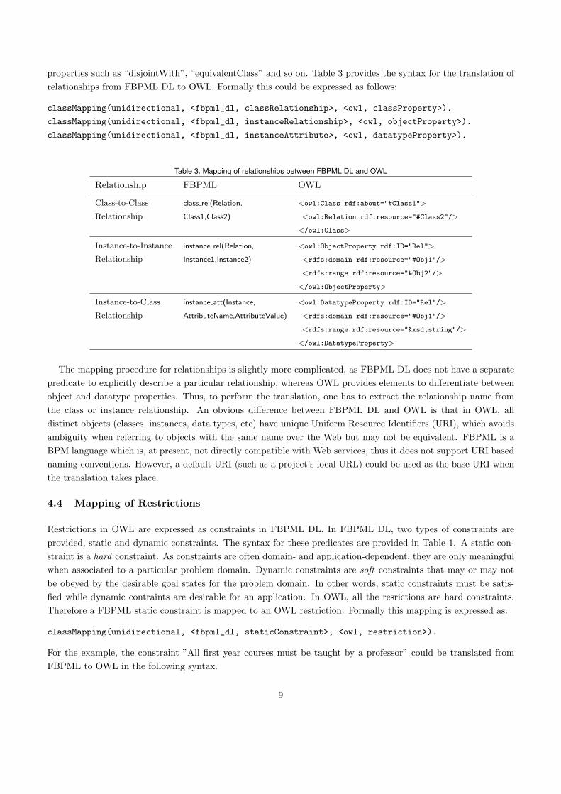
properties such as “disjointWith”, “equivalentClass” and so on. Table 3 provides the syntax for the translation ofrelationships from FBPML DL to OWL. Formally this could be expressed as follows:
classMapping(unidirectional, <fbpml_dl, classRelationship>, <owl, classProperty>).
classMapping(unidirectional, <fbpml_dl, instanceRelationship>, <owl, objectProperty>).
classMapping(unidirectional, <fbpml_dl, instanceAttribute>, <owl, datatypeProperty>).
Table 3. Mapping of relationships between FBPML DL and OWL
Relationship FBPML OWL
Class-to-Class class rel(Relation, <owl:Class rdf:about="#Class1">
Relationship Class1,Class2) <owl:Relation rdf:resource="#Class2"/>
</owl:Class>
Instance-to-Instance instance rel(Relation, <owl:ObjectProperty rdf:ID="Rel">
Relationship Instance1,Instance2) <rdfs:domain rdf:resource="#Obj1"/>
<rdfs:range rdf:resource="#Obj2"/>
</owl:ObjectProperty>
Instance-to-Class instance att(Instance, <owl:DatatypeProperty rdf:ID="Rel"/>
Relationship AttributeName,AttributeValue) <rdfs:domain rdf:resource="#Obj1"/>
<rdfs:range rdf:resource="&xsd;string"/>
</owl:DatatypeProperty>
The mapping procedure for relationships is slightly more complicated, as FBPML DL does not have a separatepredicate to explicitly describe a particular relationship, whereas OWL provides elements to differentiate betweenobject and datatype properties. Thus, to perform the translation, one has to extract the relationship name fromthe class or instance relationship. An obvious difference between FBPML DL and OWL is that in OWL, alldistinct objects (classes, instances, data types, etc) have unique Uniform Resource Identifiers (URI), which avoidsambiguity when referring to objects with the same name over the Web but may not be equivalent. FBPML is aBPM language which is, at present, not directly compatible with Web services, thus it does not support URI basednaming conventions. However, a default URI (such as a project’s local URL) could be used as the base URI whenthe translation takes place.
4.4 Mapping of Restrictions
Restrictions in OWL are expressed as constraints in FBPML DL. In FBPML DL, two types of constraints areprovided, static and dynamic constraints. The syntax for these predicates are provided in Table 1. A static con-straint is a hard constraint. As constraints are often domain- and application-dependent, they are only meaningfulwhen associated to a particular problem domain. Dynamic constraints are soft constraints that may or may notbe obeyed by the desirable goal states for the problem domain. In other words, static constraints must be satis-fied while dynamic contraints are desirable for an application. In OWL, all the resrictions are hard constraints.Therefore a FBPML static constraint is mapped to an OWL restriction. Formally this mapping is expressed as:
classMapping(unidirectional, <fbpml_dl, staticConstraint>, <owl, restriction>).
For the example, the constraint ”All first year courses must be taught by a professor” could be translated fromFBPML to OWL in the following syntax.
9
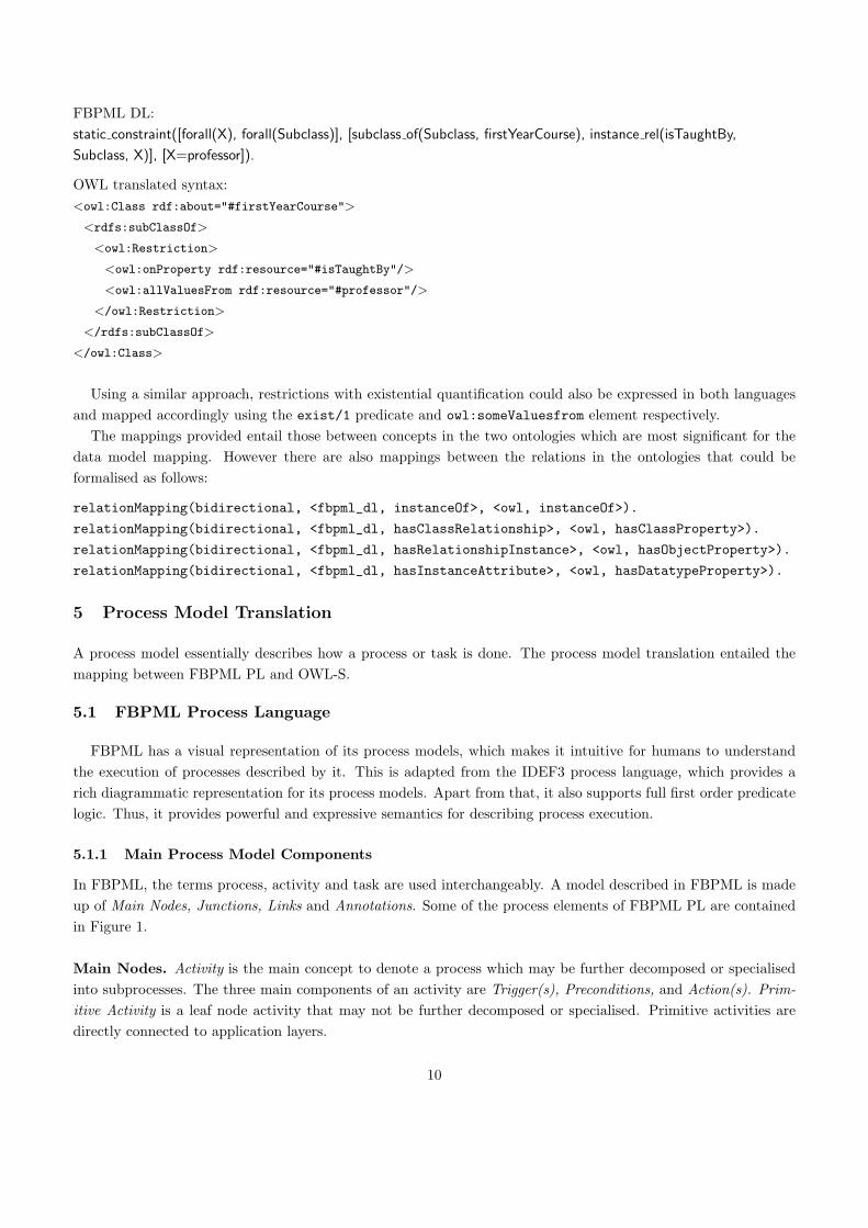
FBPML DL:static constraint([forall(X), forall(Subclass)], [subclass of(Subclass, firstYearCourse), instance rel(isTaughtBy,
Subclass, X)], [X=professor]).
OWL translated syntax:<owl:Class rdf:about="#firstYearCourse">
<rdfs:subClassOf>
<owl:Restriction>
<owl:onProperty rdf:resource="#isTaughtBy"/>
<owl:allValuesFrom rdf:resource="#professor"/>
</owl:Restriction>
</rdfs:subClassOf>
</owl:Class>
Using a similar approach, restrictions with existential quantification could also be expressed in both languagesand mapped accordingly using the exist/1 predicate and owl:someValuesfrom element respectively.
The mappings provided entail those between concepts in the two ontologies which are most significant for thedata model mapping. However there are also mappings between the relations in the ontologies that could beformalised as follows:
relationMapping(bidirectional, <fbpml_dl, instanceOf>, <owl, instanceOf>).
relationMapping(bidirectional, <fbpml_dl, hasClassRelationship>, <owl, hasClassProperty>).
relationMapping(bidirectional, <fbpml_dl, hasRelationshipInstance>, <owl, hasObjectProperty>).
relationMapping(bidirectional, <fbpml_dl, hasInstanceAttribute>, <owl, hasDatatypeProperty>).
5 Process Model Translation
A process model essentially describes how a process or task is done. The process model translation entailed themapping between FBPML PL and OWL-S.
5.1 FBPML Process Language
FBPML has a visual representation of its process models, which makes it intuitive for humans to understandthe execution of processes described by it. This is adapted from the IDEF3 process language, which provides arich diagrammatic representation for its process models. Apart from that, it also supports full first order predicatelogic. Thus, it provides powerful and expressive semantics for describing process execution.
5.1.1 Main Process Model Components
In FBPML, the terms process, activity and task are used interchangeably. A model described in FBPML is madeup of Main Nodes, Junctions, Links and Annotations. Some of the process elements of FBPML PL are containedin Figure 1.
Main Nodes. Activity is the main concept to denote a process which may be further decomposed or specialisedinto subprocesses. The three main components of an activity are Trigger(s), Preconditions, and Action(s). Prim-itive Activity is a leaf node activity that may not be further decomposed or specialised. Primitive activities aredirectly connected to application layers.
10
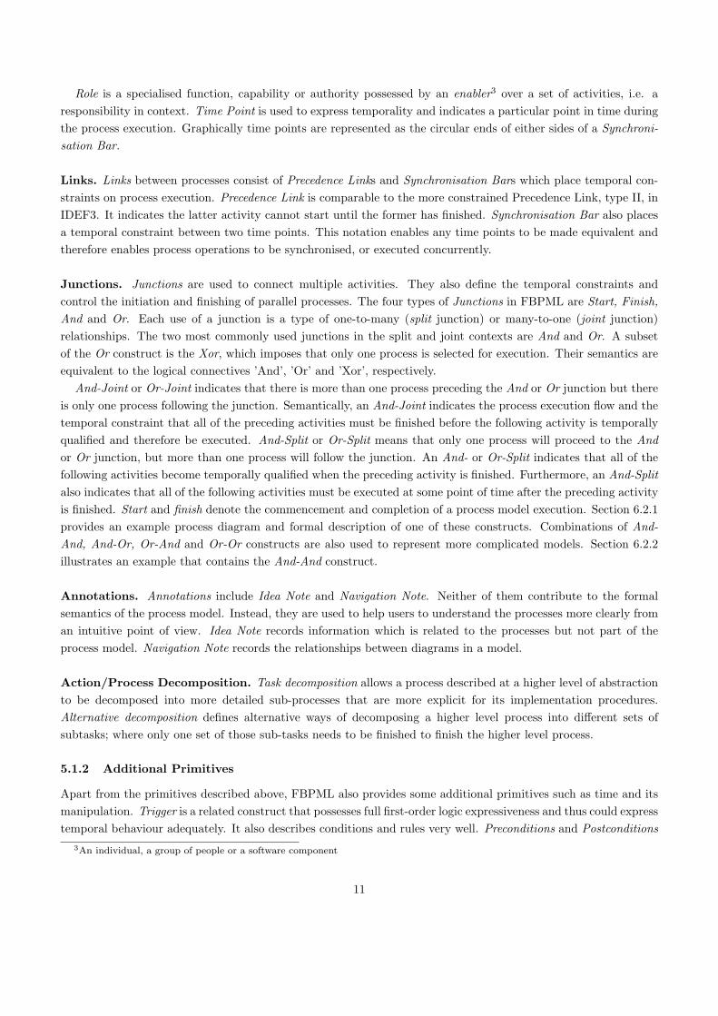
Role is a specialised function, capability or authority possessed by an enabler3 over a set of activities, i.e. aresponsibility in context. Time Point is used to express temporality and indicates a particular point in time duringthe process execution. Graphically time points are represented as the circular ends of either sides of a Synchroni-sation Bar.
Links. Links between processes consist of Precedence Links and Synchronisation Bars which place temporal con-straints on process execution. Precedence Link is comparable to the more constrained Precedence Link, type II, inIDEF3. It indicates the latter activity cannot start until the former has finished. Synchronisation Bar also placesa temporal constraint between two time points. This notation enables any time points to be made equivalent andtherefore enables process operations to be synchronised, or executed concurrently.
Junctions. Junctions are used to connect multiple activities. They also define the temporal constraints andcontrol the initiation and finishing of parallel processes. The four types of Junctions in FBPML are Start, Finish,And and Or. Each use of a junction is a type of one-to-many (split junction) or many-to-one (joint junction)relationships. The two most commonly used junctions in the split and joint contexts are And and Or. A subsetof the Or construct is the Xor, which imposes that only one process is selected for execution. Their semantics areequivalent to the logical connectives ’And’, ’Or’ and ’Xor’, respectively.
And-Joint or Or-Joint indicates that there is more than one process preceding the And or Or junction but thereis only one process following the junction. Semantically, an And-Joint indicates the process execution flow and thetemporal constraint that all of the preceding activities must be finished before the following activity is temporallyqualified and therefore be executed. And-Split or Or-Split means that only one process will proceed to the Andor Or junction, but more than one process will follow the junction. An And- or Or-Split indicates that all of thefollowing activities become temporally qualified when the preceding activity is finished. Furthermore, an And-Splitalso indicates that all of the following activities must be executed at some point of time after the preceding activityis finished. Start and finish denote the commencement and completion of a process model execution. Section 6.2.1provides an example process diagram and formal description of one of these constructs. Combinations of And-And, And-Or, Or-And and Or-Or constructs are also used to represent more complicated models. Section 6.2.2illustrates an example that contains the And-And construct.
Annotations. Annotations include Idea Note and Navigation Note. Neither of them contribute to the formalsemantics of the process model. Instead, they are used to help users to understand the processes more clearly froman intuitive point of view. Idea Note records information which is related to the processes but not part of theprocess model. Navigation Note records the relationships between diagrams in a model.
Action/Process Decomposition. Task decomposition allows a process described at a higher level of abstractionto be decomposed into more detailed sub-processes that are more explicit for its implementation procedures.Alternative decomposition defines alternative ways of decomposing a higher level process into different sets ofsubtasks; where only one set of those sub-tasks needs to be finished to finish the higher level process.
5.1.2 Additional Primitives
Apart from the primitives described above, FBPML also provides some additional primitives such as time and itsmanipulation. Trigger is a related construct that possesses full first-order logic expressiveness and thus could expresstemporal behaviour adequately. It also describes conditions and rules very well. Preconditions and Postconditions
3An individual, a group of people or a software component
11

are used in conjunction with conditional statements that are equivalent to if-then-else constructs in conventionalprogramming terms. FBPML also describes event and process life status and cycles. Each node (or process) inFBPML has its attributes, such as Process: Instance Id, Process type, Life status, Priority, Average time cost,Begin/End time, Service Requester/Service Provider, Trigger, Preconditions, Actions, Postconditions.
5.1.3 FBPML Formal Definition
While the FBPML graphical representation provides intuitive reasoning, the FBPML formal definition allows formachine processability. The following definition has been extracted from [9]4:
Main Nodes:activity(ID, Name, Trigger, Precondition, Postcondition, Action, Description).
primitive activity(ID, Name, Trigger, Precondition, Postcondition, Action, Description).
Action:action(ActionType, Class, Instance).
Junctions:start(ActivityName).
junction(JunctionType, PreActivities, PostActivities).
Links:link(PrecedingActivity, ProceedingActivity).
syn(begin/end(Activity1), begin/end(Activity2))5.
5.2 OWL-S Process Components
OWL-S is made up of four main ontologies or classes; Service, Service Profile, Service Model andGrounding. The basic properties that describe an OWL-S process are Input, Output, Precondition andEffects. For the purpose of the process model mapping, attention is given to a subclass of Service Model,the class Process, which most appropriately defines the execution of a process.
5.2.1 Process
The class Process draws upon well-established work in a variety of fields, including work in AI on standardisationsof planning languages, work in programming languages and distributed systems, emerging standards in processmodelling and workflow technology such as Process Specification Language (PSL) and the Workflow ManagementCoalition effort [31], work on verb semantics and event structure, previous work on action-inspired Web servicemarkup, work in AI on modelling complex actions and work in agent communication languages. Subclasses ofProcess are Atomic Process, Simple Process and Composite Process.
Atomic Processes are directly invocable, have no subprocesses and execute in a single step. They take an inputmessage, process it, and then return their output message. For each atomic process, there must be provided a
4The initial definition for activity/6 and primitive activity/6 have been extended to activity/7 and primitive activity/7 by the inclusion
of Description.5This is a shorthand for the four possible combinations: syn(begin(Activity1),begin(Activity2)), syn(begin(Activity1),end(Activity2)),
syn(end(Activity1),begin(Activity2)) and syn(end(Activity1),end(Activity2)).
12
grounding that enables a service requester to construct messages to the process from its inputs and deconstructreplies.
Simple Processes are not invocable and are not associated with a grounding, but, like atomic processes, they areconceived of as having single-step executions. Simple processes are used as elements of abstracton; a simple processmay be used either to provide a view of some atomic process, or a simplified representation of some compositeprocess (for purposes of planning and reasoning).
Composite Processes are decomposable into other (non-composite or composite) processes. A precise specifica-tion of what it means to perform a process has not yet been given, but it applies that if a composite is a Sequence,then the client sends a series of messages that invoke every step in order. One crucial feature of a compositeprocess is its specification of how its inputs are accepted by particular subprocesses, and how its various outputsare produced by particular subprocesses.
5.2.2 Parameter and Result
Parameter stores inputs, outputs and results. It is a subclass of the SWRL’s swrl:Variable construct with atype description and an optional value expression, whereby the value of a constant parameter could be stored, forinstance. Input, Output, Local and ResultVar are subclasses of Parameter. Local Parameters may only be usedwith Atomic Processes. Their function is to identify variables whose scope is the process as a whole, so that whenthey are bound in preconditions, they can be referenced in outputs and effects. Outputs are process parametersthat are associated with descriptions by OutputBindings associated with particular result conditions. Result haszero or more inCondition properties, withOutput properties, hasResultVar properties and hasEffect properties.
5.2.3 Control Constructs
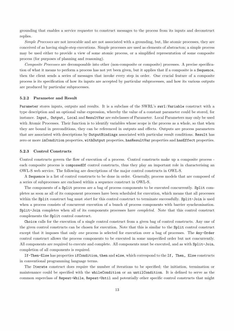
Control constructs govern the flow of execution of a process. Control constructs make up a composite process -each composite process is composedOf control constructs, thus they play an important role in characterising anOWL-S web service. The following are descriptions of the major control constructs in OWL-S.
A Sequence is a list of control constructs to be done in order. Generally, process models that are composed ofa series of subprocesses are enclosed within a sequence construct in OWL-S.
The components of a Split process are a bag of process components to be executed concurrently. Split com-pletes as soon as all of its component processes have been scheduled for execution, which means that all processeswithin the Split construct bag must start for this control construct to terminate successfully. Split-Join is usedwhen a process consists of concurrent execution of a bunch of process components with barrier synchronisation.Split-Join completes when all of its components processes have completed. Note that this control constructcomplements the Split control construct.
Choice calls for the execution of a single control construct from a given bag of control constructs. Any one ofthe given control constructs can be chosen for execution. Note that this is similar to the Split control constructexcept that it imposes that only one process is selected for execution over a bag of processes. The Any-Order
control construct allows the process components to be executed in some unspecified order but not concurrently.All components are required to execute and complete. All components must be executed, and as with Split-Join,completion of all components is required.
If-Then-Else has properties ifCondition, then and else, which correspond to the If, Then, Else constructsin conventional programming language terms.
The Iterate construct does require the number of iterations to be specified; the initiation, termination ormaintenance could be specified with the whileCondition or an untilCondition. It is defined to serve as thecommon superclass of Repeat-While, Repeat-Until and potentially other specific control constructs that might
13
be needed in the future. Repeat-While and Repeat-Until control constructs iterate until a condition becomes falseor true, as in most programming language conventions. Thus, Repeat-While may never act, whereas Repeat-Untilalways acts at least once.
5.2.4 Expression
Expression contains ontology elements for capturing conditions and effects, it is the superclass of Condition andEffect. Conditions, (preconditions in FBPML terms), is defined as a class of logical expressions, whose truthvalue can be determined for further action, for instance it could be used with the If-Then-Else control construct.Expressions can be in any allowed logical language, and use parameters (primarily input and local) variables.Logical expressions for preconditions, effects and result conditions are represented in a logical formalism. SWRLhas been the choice of extension for OWL due to its well formed semantics.
5.3 Ontologies of the Process Models
Figure 6 describes the process model ontology for FBPML. Note that the Model Construct concept is not partof the FBPML PL notation, but it is added to the ontology to assist the mapping effort. As the process models aremore extensive, the primitives are mapped first before applying mapping principles for process model translation.
6 Process Model Mapping
The primitives in FBPML PL were mapped to the primitives in OWL-S. The formal mapping of the primitives isgiven below:
classMapping(unidirectional, <fbpml_pl, activity>, <owl_s, compositeProcess>).
classMapping(unidirectional, <fbpml_pl, instanceRelationship>, <owl_s, atomicProcess>).
classMapping(unidirectional, <fbpml_pl, role>, <owl_s, participant>).
classMapping(unidirectional, <fbpml_pl, and_Joint>, <owl_s, splitJoin>).
classMapping(unidirectional, <fbpml_pl, and_Split>, <owl_s, split>).
classMapping(unidirectional, <fbpml_pl, or_Split>, <owl_s, repeatWhile>).
classMapping(unidirectional, <fbpml_pl, xor>, <owl_s, choice>).
classMapping(unidirectional, <fbpml_pl, precondition>, <owl_s, precondition>).
classMapping(unidirectional, <fbpml_pl, postcondition>, <owl_s, effect>).
classMapping(unidirectional, <fbpml_pl, action>, <owl_s, atomicProcess>).
classMapping(unidirectional, <fbpml_pl, conditionalAction>, <owl_s, ifThenElse>).
classMapping(unidirectional, <fbpml_pl, and_And>, <owl_s, splitJoin>).
Several observations were made from the mapping of primitives between their process elements. In FBPML, arole is a responsibility in context; usually in the form of a Provider or a Requester. In OWL-S the Participant
instances include TheClient and TheServer. Thus the Requester role corresponds to TheClient in OWL-S and theProvider role corresponds to TheServer OWL-S. FBPML’s notion of role is richer and could refer to an individual,a group of people or software components or a combination of the above [9].
The time ontology is used currently in limited ways in the process specification in OWL-S (described inhttp://www.isi.edu/~pan/damltime/time-entry.owl). Although there is no OWL-S construct that maps to FBPML’sPrecedence Link, the order of execution of processes within a sequence enclosed by <objList:first>...</objList:fir-
st> and <objList:rest>...</objList:rest>.
14

Table 4. Summary of mapping between FBPML and OWL-S process primitives
Primitive FBPML OWL-S
Main Nodes Activity Composite Process
Primitive Activity Atomic Process
Role Participant
Time Point See Note
Links Precedence Link (part of) Sequence
Synchronisation Bar See Note
Junctions Start See Note
Finish See Note
And-Joint Split-Join
Or-Joint See Note
And-Split Split
Or-Split Repeat-While/Until
Xor-Junction Choice
Primitive FBPML OWL-S
Annotations Idea Note See Note below
Navigation Note See Note below
Process Precondition Precondition
Components Trigger See Note below
Postcondition Effect/Output
Precondition,Trigger Input
Action Atomic Process
Conditional Action If-Then-Else
Combination And-And Split-Join
Model And-Or See Note below
Constructs Or-And See Note below
Or-Or See Note below
Note: Limited (or no) equivalent convention provided by OWL-S.
The And-Split is slightly modified (with barrier synchronisation) to correspond to the OWL-S Split constructwhere the processes that branch into the junctions are synchronised. The OWL-S Choice construct selects oneprocess out of many for execution, which is equivalent to the Xor in FBPML, however, OWL-S does not provide adirect equivalent for the Or construct. The Xor junction is subsumed by the Or junction and has been utilised bymore recent applications to make it more explicit for automation when bridging to (Semantic Web or Web service)methods that do not have Or junctions.
Since OWL-S does not support the notion of trigger, the combination of Precondition and Trigger in FBPMLapproximately map to Precondition in OWL-S. Postcondition in FBPML describes the effects and conditions whichmust hold true after the execution of a process.
In FBPML, an Action is the actual execution behaviours in a process model which can be stored in a repository.The advantage of the action repository is that actions can be reused and shared. Therefore an Action approximatelymaps to OWL-S Atomic Process. A precise specification of what it means to perform a process in OWL-S hasnot been given yet. Table 4 summarises the mapping of the primitives between FBPML PL and OWL-S processontology.
6.1 Process Model Mapping Principles
After determining the matching primitives, the mapping was followed through using component models consistingof sequences, and junctions. The procedure for the mapping of component models involved breaking down eachprocess into a composite process, and considering a single construct to be translated, such as Sequence, Split,
Split-Join or Choice. The whole composite process consists of a sequence of at most two processes. This componentmodel translation could be incrementally extended to cater for more complex models via a layered model translation.When the procedure is refined to cater for all process models, a general methodology for the process model mappingwas achieved (refined from [12]).
1. Decompose FBPML process model in a top-down order.
15
2. Translate model into a sequence process in OWL-S.
3. All activities between start and finish nodes are composite components of the sequence process.
4. Exhaustively decompose each composite component into a sequence of its basic process component, until asfar as an atomic process construct.
6.2 Working Examples
A step-by-step demonstration of the process model translation is provided to illustrate the application of theprocess model mapping principles. The OWL-S representations in this section are obtained using the automatictranslator described in Section 7.
6.2.1 Component Models
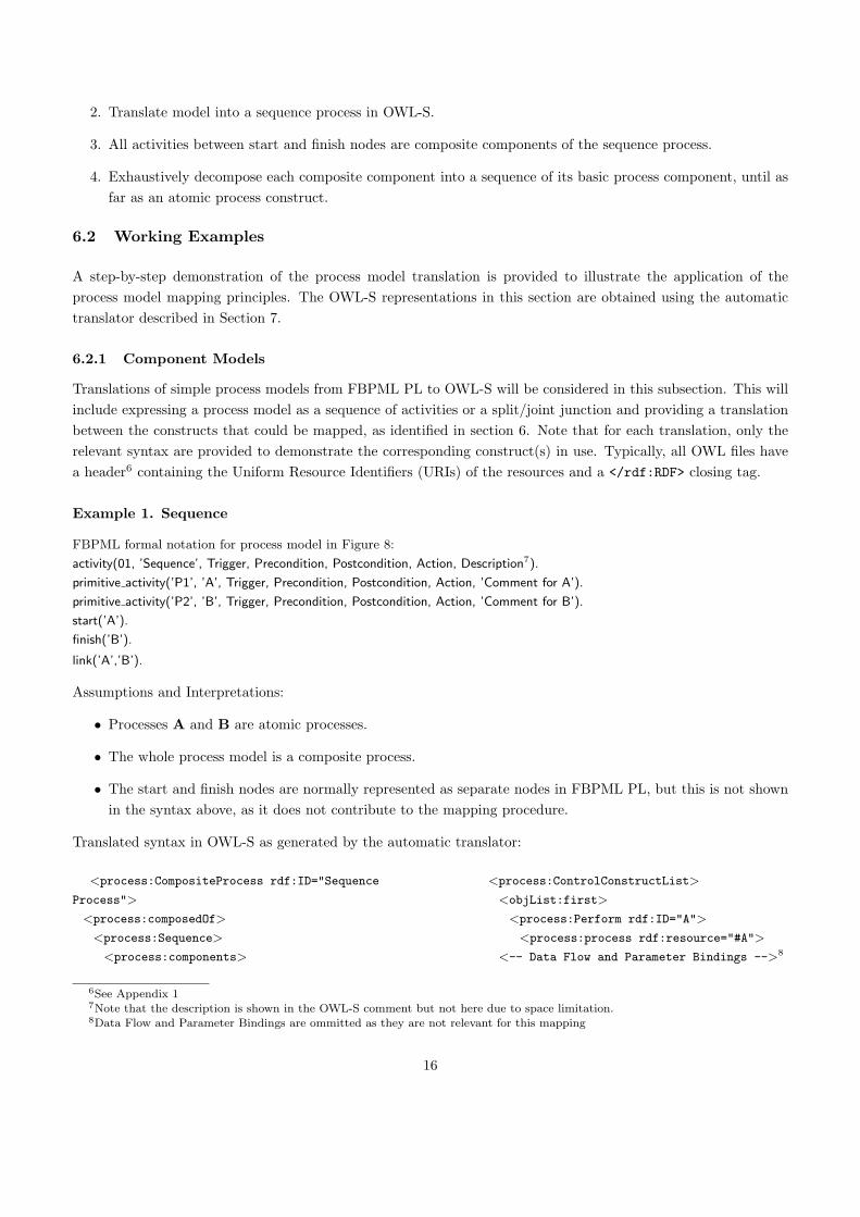
Translations of simple process models from FBPML PL to OWL-S will be considered in this subsection. This willinclude expressing a process model as a sequence of activities or a split/joint junction and providing a translationbetween the constructs that could be mapped, as identified in section 6. Note that for each translation, only therelevant syntax are provided to demonstrate the corresponding construct(s) in use. Typically, all OWL files havea header6 containing the Uniform Resource Identifiers (URIs) of the resources and a </rdf:RDF> closing tag.
Example 1. Sequence
FBPML formal notation for process model in Figure 8:
activity(01, ’Sequence’, Trigger, Precondition, Postcondition, Action, Description7).
primitive activity(’P1’, ’A’, Trigger, Precondition, Postcondition, Action, ’Comment for A’).
primitive activity(’P2’, ’B’, Trigger, Precondition, Postcondition, Action, ’Comment for B’).
start(’A’).
finish(’B’).
link(’A’,’B’).
Assumptions and Interpretations:
• Processes A and B are atomic processes.
• The whole process model is a composite process.
• The start and finish nodes are normally represented as separate nodes in FBPML PL, but this is not shownin the syntax above, as it does not contribute to the mapping procedure.
Translated syntax in OWL-S as generated by the automatic translator:
<process:CompositeProcess rdf:ID="Sequence
Process">
<process:composedOf>
<process:Sequence>
<process:components>
<process:ControlConstructList>
<objList:first>
<process:Perform rdf:ID="A">
<process:process rdf:resource="#A">
<-- Data Flow and Parameter Bindings -->8
6See Appendix 17Note that the description is shown in the OWL-S comment but not here due to space limitation.8Data Flow and Parameter Bindings are ommitted as they are not relevant for this mapping
16
</process:Perform>
</objList:first>
<objList:rest>
<process:ControlConstructList>
<objList:first>
<process:Perform rdf:ID="B">
<process:process rdf:resource="#B">
<-- Data Flow and Parameter Bindings
ommitted -->
</process:Perform>
</objList:first>
<objList:rest rdf:resource="&objList;#nil"/>
</process:ControlConstructList>
</objList:rest>
</process:ControlConstructList>
</process:components>
</process:Sequence>
</process:composedOf>
</process:CompositeProcess>
<-- End of Sequence Process -->
<process:AtomicProcess rdf:ID="A">
<-- Input and Output not shown -->
<rdfs:comment>
Comment for A
</rdfs:comment>
</process:AtomicProcess>
<process:AtomicProcess rdf:ID="B">
<-- Input and Output not shown -->
<rdfs:comment>
Comment for B
</rdfs:comment>
</process:AtomicProcess>
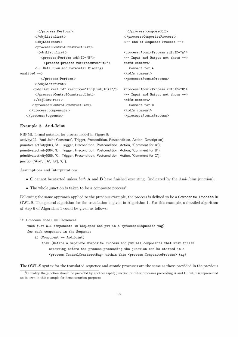
Example 2. And-Joint
FBPML formal notation for process model in Figure 9:
activity(02, ’And-Joint Construct’, Trigger, Precondition, Postcondition, Action, Description).
primitive activity(003, ’A’, Trigger, Precondition, Postcondition, Action, ’Comment for A’).
primitive activity(004, ’B’, Trigger, Precondition, Postcondition, Action, ’Comment for B’).
primitive activity(005, ’C’, Trigger, Precondition, Postcondition, Action, ’Comment for C’).
junction(’And’, [’A’, ’B’], ’C’).
Assumptions and Interpretations:
• C cannot be started unless both A and B have finished executing. (indicated by the And-Joint junction).
• The whole junction is taken to be a composite process9.
Following the same approach applied to the previous example, the process is defined to be a Composite Process inOWL-S. The general algorithm for the translation is given in Algorithm 1. For this example, a detailed algorithmof step 6 of Algorithm 1 could be given as follows:
if (Process Model == Sequence)
then (Get all components in Sequence and put in a <process:Sequence> tag)
for each component in the Sequence
if (Component == And Joint)
then (Define a separate Composite Process and put all components that must finish
executing before the process proceeding the junction can be started in a
<process:ControlConstructBag> within this <process:CompositeProcess> tag)
The OWL-S syntax for the translated sequence and atomic processes are the same as those provided in the previous9In reality the junction should be preceded by another (split) junction or other processes preceeding A and B, but it is represented
on its own in this example for demonstration purposes
17
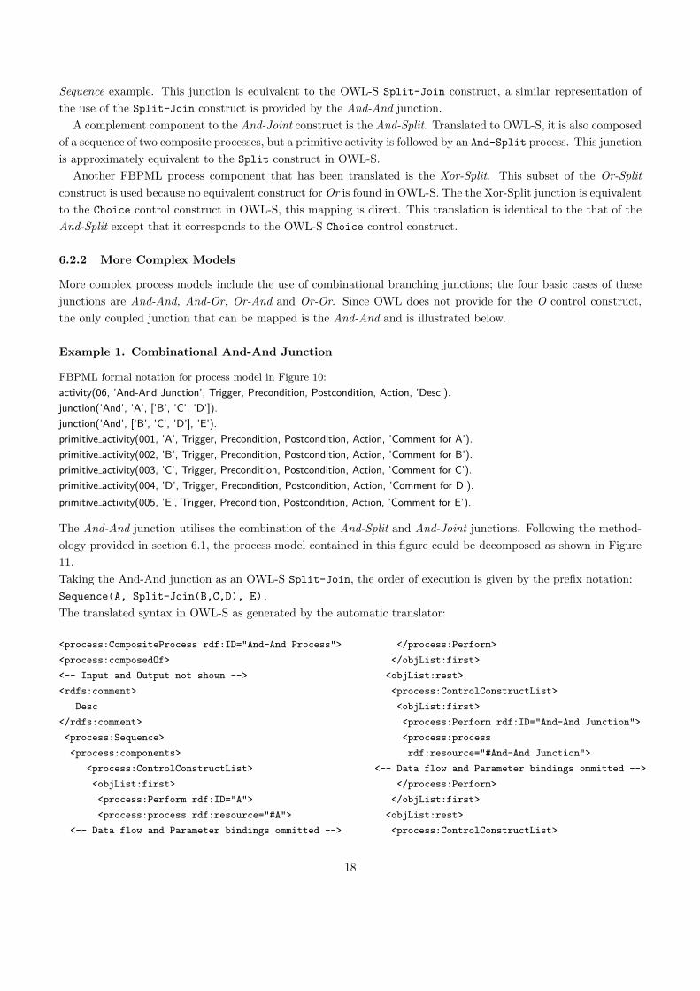
Sequence example. This junction is equivalent to the OWL-S Split-Join construct, a similar representation ofthe use of the Split-Join construct is provided by the And-And junction.
A complement component to the And-Joint construct is the And-Split. Translated to OWL-S, it is also composedof a sequence of two composite processes, but a primitive activity is followed by an And-Split process. This junctionis approximately equivalent to the Split construct in OWL-S.
Another FBPML process component that has been translated is the Xor-Split. This subset of the Or-Splitconstruct is used because no equivalent construct for Or is found in OWL-S. The the Xor-Split junction is equivalentto the Choice control construct in OWL-S, this mapping is direct. This translation is identical to the that of theAnd-Split except that it corresponds to the OWL-S Choice control construct.
6.2.2 More Complex Models
More complex process models include the use of combinational branching junctions; the four basic cases of thesejunctions are And-And, And-Or, Or-And and Or-Or. Since OWL does not provide for the O control construct,the only coupled junction that can be mapped is the And-And and is illustrated below.
Example 1. Combinational And-And Junction
FBPML formal notation for process model in Figure 10:
activity(06, ’And-And Junction’, Trigger, Precondition, Postcondition, Action, ’Desc’).
junction(’And’, ’A’, [’B’, ’C’, ’D’]).
junction(’And’, [’B’, ’C’, ’D’], ’E’).
primitive activity(001, ’A’, Trigger, Precondition, Postcondition, Action, ’Comment for A’).
primitive activity(002, ’B’, Trigger, Precondition, Postcondition, Action, ’Comment for B’).
primitive activity(003, ’C’, Trigger, Precondition, Postcondition, Action, ’Comment for C’).
primitive activity(004, ’D’, Trigger, Precondition, Postcondition, Action, ’Comment for D’).
primitive activity(005, ’E’, Trigger, Precondition, Postcondition, Action, ’Comment for E’).
The And-And junction utilises the combination of the And-Split and And-Joint junctions. Following the method-ology provided in section 6.1, the process model contained in this figure could be decomposed as shown in Figure11.Taking the And-And junction as an OWL-S Split-Join, the order of execution is given by the prefix notation:Sequence(A, Split-Join(B,C,D), E).
The translated syntax in OWL-S as generated by the automatic translator:
<process:CompositeProcess rdf:ID="And-And Process">
<process:composedOf>
<-- Input and Output not shown -->
<rdfs:comment>
Desc
</rdfs:comment>
<process:Sequence>
<process:components>
<process:ControlConstructList>
<objList:first>
<process:Perform rdf:ID="A">
<process:process rdf:resource="#A">
<-- Data flow and Parameter bindings ommitted -->
</process:Perform>
</objList:first>
<objList:rest>
<process:ControlConstructList>
<objList:first>
<process:Perform rdf:ID="And-And Junction">
<process:process
rdf:resource="#And-And Junction">
<-- Data flow and Parameter bindings ommitted -->
</process:Perform>
</objList:first>
<objList:rest>
<process:ControlConstructList>
18
<objList:first>
<process:Perform rdf:ID="E">
<process:process rdf:resource="#E">
<-- Data flow and Parameter bindings ommitted -->
</process:Perform>
</objList:first>
<objList:rest rdf:resource="&objList;#nil"/>
</process:ControlConstructList>
</objList:rest>
</process:ControlConstructList>
</objList:rest>
</process:ControlConstructList>
</process:components>
</process:Sequence>
</process:composedOf>
</process:CompositeProcess>
<-- End of And-And Process -->
<process:CompositeProcess rdf:ID="And-And Junction">
<process:composedOf>
<process:Split-Join>
<process:components>
<process:ControlConstructBag>
<objList:first>
<process:Perform rdf:ID="B">
<process:process rdf:resource="#B">
<-- Data flow and Parameter bindings ommitted -->
</process:Perform>
</objList:first>
<objList:rest>
<process:ControlConstructBag>
<objList:first>
<process:Perform rdf:ID="C">
<process:process rdf:resource="#C">
<-- Data flow and Parameter bindings ommitted -->
</process:Perform>
</objList:first>
<objList:rest>
<process:ControlConstructBag>
<objList:first>
<process:Perform rdf:ID="D">
<process:process rdf:resource="#D">
<-- Data flow and Parameter bindings ommitted -->
</process:Perform>
</objList:first>
<objList:rest rdf:resource="&objList;#nil"/>
</process:ControlConstructBag>
</objList:rest>
</process:ControlConstructBag>
</objList:rest>
</process:ControlConstructBag>
</process:components>
</process:Split-Join>
</process:composedOf>
</process:CompositeProcess>
<-- End of And-And Junction -->
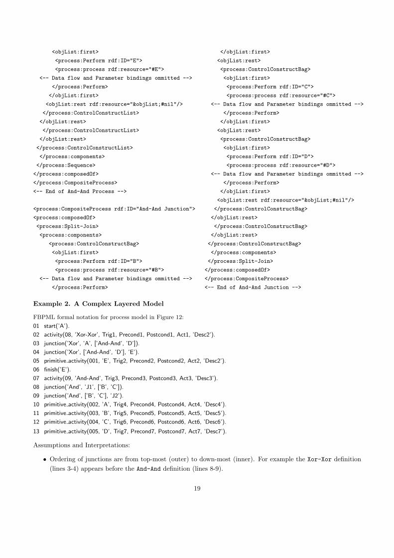
Example 2. A Complex Layered Model
FBPML formal notation for process model in Figure 12:
01 start(’A’).
02 activity(08, ’Xor-Xor’, Trig1, Precond1, Postcond1, Act1, ’Desc2’).
03 junction(’Xor’, ’A’, [’And-And’, ’D’]).
04 junction(’Xor’, [’And-And’, ’D’], ’E’).
05 primitive activity(001, ’E’, Trig2, Precond2, Postcond2, Act2, ’Desc2’).
06 finish(’E’).
07 activity(09, ’And-And’, Trig3, Precond3, Postcond3, Act3, ’Desc3’).
08 junction(’And’, ’J1’, [’B’, ’C’]).
09 junction(’And’, [’B’, ’C’], ’J2’).
10 primitive activity(002, ’A’, Trig4, Precond4, Postcond4, Act4, ’Desc4’).
11 primitive activity(003, ’B’, Trig5, Precond5, Postcond5, Act5, ’Desc5’).
12 primitive activity(004, ’C’, Trig6, Precond6, Postcond6, Act6, ’Desc6’).
13 primitive activity(005, ’D’, Trig7, Precond7, Postcond7, Act7, ’Desc7’).
Assumptions and Interpretations:
• Ordering of junctions are from top-most (outer) to down-most (inner). For example the Xor-Xor definition(lines 3-4) appears before the And-And definition (lines 8-9).
19
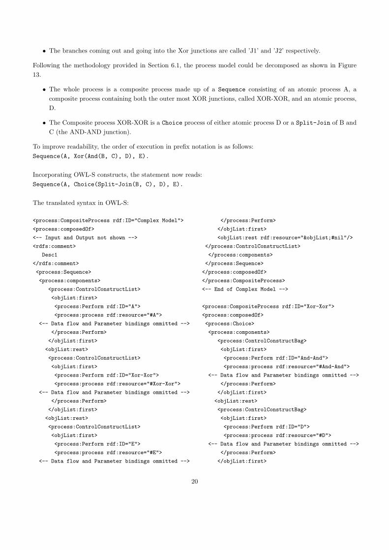
• The branches coming out and going into the Xor junctions are called ’J1’ and ’J2’ respectively.
Following the methodology provided in Section 6.1, the process model could be decomposed as shown in Figure13.
• The whole process is a composite process made up of a Sequence consisting of an atomic process A, acomposite process containing both the outer most XOR junctions, called XOR-XOR, and an atomic process,D.
• The Composite process XOR-XOR is a Choice process of either atomic process D or a Split-Join of B andC (the AND-AND junction).
To improve readability, the order of execution in prefix notation is as follows:Sequence(A, Xor(And(B, C), D), E).
Incorporating OWL-S constructs, the statement now reads:Sequence(A, Choice(Split-Join(B, C), D), E).
The translated syntax in OWL-S:
<process:CompositeProcess rdf:ID="Complex Model">
<process:composedOf>
<-- Input and Output not shown -->
<rdfs:comment>
Desc1
</rdfs:comment>
<process:Sequence>
<process:components>
<process:ControlConstructList>
<objList:first>
<process:Perform rdf:ID="A">
<process:process rdf:resource="#A">
<-- Data flow and Parameter bindings ommitted -->
</process:Perform>
</objList:first>
<objList:rest>
<process:ControlConstructList>
<objList:first>
<process:Perform rdf:ID="Xor-Xor">
<process:process rdf:resource="#Xor-Xor">
<-- Data flow and Parameter bindings ommitted -->
</process:Perform>
</objList:first>
<objList:rest>
<process:ControlConstructList>
<objList:first>
<process:Perform rdf:ID="E">
<process:process rdf:resource="#E">
<-- Data flow and Parameter bindings ommitted -->
</process:Perform>
</objList:first>
<objList:rest rdf:resource="&objList;#nil"/>
</process:ControlConstructList>
</process:components>
</process:Sequence>
</process:composedOf>
</process:CompositeProcess>
<-- End of Complex Model -->
<process:CompositeProcess rdf:ID="Xor-Xor">
<process:composedOf>
<process:Choice>
<process:components>
<process:ControlConstructBag>
<objList:first>
<process:Perform rdf:ID="And-And">
<process:process rdf:resource="#And-And">
<-- Data flow and Parameter bindings ommitted -->
</process:Perform>
</objList:first>
<objList:rest>
<process:ControlConstructBag>
<objList:first>
<process:Perform rdf:ID="D">
<process:process rdf:resource="#D">
<-- Data flow and Parameter bindings ommitted -->
</process:Perform>
</objList:first>
20
<objList:rest rdf:resource="&objList;#nil"/>
</process:ControlConstructBag>
</objList:rest>
</process:ControlConstructBag>
</process:components>
</process:Choice>
</process:composedOf>
</process:CompositeProcess>
<-- End of Xor-Xor -->
<process:CompositeProcess rdf:ID="And-And">
<process:composedOf>
<process:Split-Join>
<process:components>
<process:ControlConstructBag>
<objList:first>
<process:Perform rdf:ID="B">
<process:process rdf:resource="#B">
<-- Data flow and Parameter bindings ommitted -->
</process:Perform>
</objList:first>
<objList:rest>
<process:ControlConstructBag>
<objList:first>
<process:Perform rdf:ID="C">
<process:process rdf:resource="#C">
<-- Data flow and Parameter bindings ommitted -->
</process:Perform>
</objList:first>
<objList:rest rdf:resource="&objList;#nil"/>
</process:ControlConstructBag>
</objList:rest>
</process:ControlConstructBag>
</process:components>
</process:Split-Join>
</process:composedOf>
</process:CompositeProcess>
<-- End of And-And -->
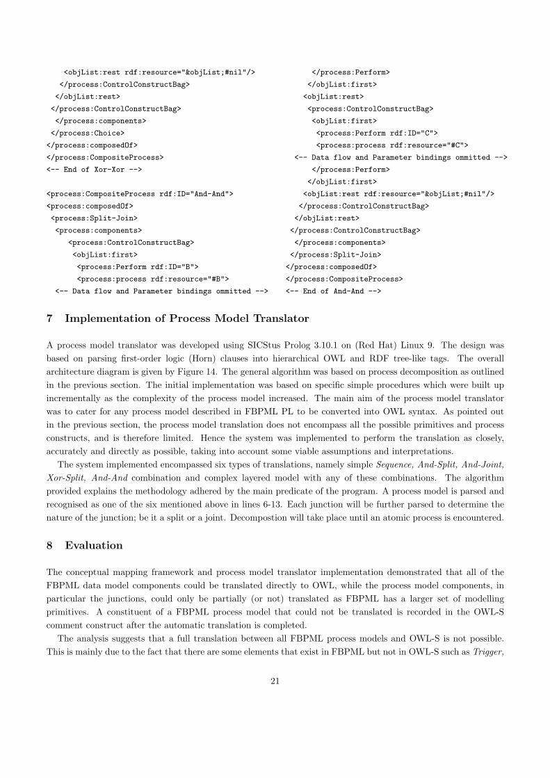
7 Implementation of Process Model Translator
A process model translator was developed using SICStus Prolog 3.10.1 on (Red Hat) Linux 9. The design wasbased on parsing first-order logic (Horn) clauses into hierarchical OWL and RDF tree-like tags. The overallarchitecture diagram is given by Figure 14. The general algorithm was based on process decomposition as outlinedin the previous section. The initial implementation was based on specific simple procedures which were built upincrementally as the complexity of the process model increased. The main aim of the process model translatorwas to cater for any process model described in FBPML PL to be converted into OWL syntax. As pointed outin the previous section, the process model translation does not encompass all the possible primitives and processconstructs, and is therefore limited. Hence the system was implemented to perform the translation as closely,accurately and directly as possible, taking into account some viable assumptions and interpretations.
The system implemented encompassed six types of translations, namely simple Sequence, And-Split, And-Joint,Xor-Split, And-And combination and complex layered model with any of these combinations. The algorithmprovided explains the methodology adhered by the main predicate of the program. A process model is parsed andrecognised as one of the six mentioned above in lines 6-13. Each junction will be further parsed to determine thenature of the junction; be it a split or a joint. Decompostion will take place until an atomic process is encountered.
8 Evaluation
The conceptual mapping framework and process model translator implementation demonstrated that all of theFBPML data model components could be translated directly to OWL, while the process model components, inparticular the junctions, could only be partially (or not) translated as FBPML has a larger set of modellingprimitives. A constituent of a FBPML process model that could not be translated is recorded in the OWL-Scomment construct after the automatic translation is completed.
The analysis suggests that a full translation between all FBPML process models and OWL-S is not possible.This is mainly due to the fact that there are some elements that exist in FBPML but not in OWL-S such as Trigger,
21
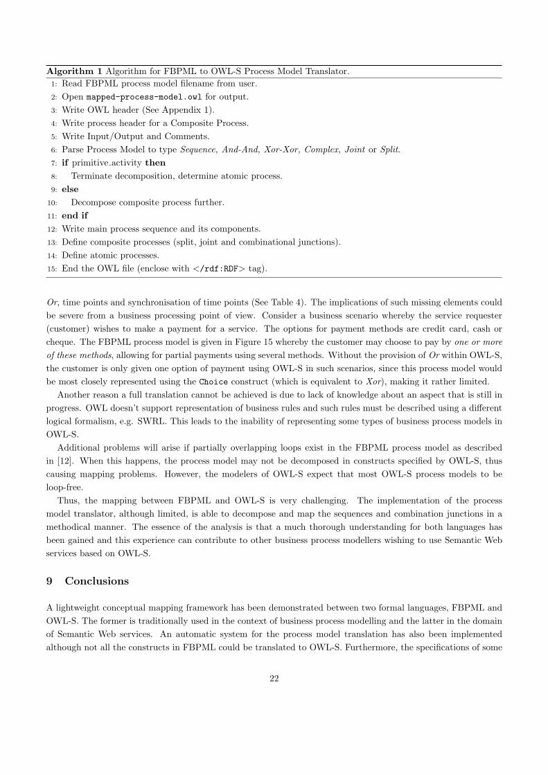
Algorithm 1 Algorithm for FBPML to OWL-S Process Model Translator.1: Read FBPML process model filename from user.2: Open mapped-process-model.owl for output.3: Write OWL header (See Appendix 1).4: Write process header for a Composite Process.5: Write Input/Output and Comments.6: Parse Process Model to type Sequence, And-And, Xor-Xor, Complex, Joint or Split.7: if primitive activity then8: Terminate decomposition, determine atomic process.9: else
10: Decompose composite process further.11: end if12: Write main process sequence and its components.13: Define composite processes (split, joint and combinational junctions).14: Define atomic processes.15: End the OWL file (enclose with </rdf:RDF> tag).
Or, time points and synchronisation of time points (See Table 4). The implications of such missing elements couldbe severe from a business processing point of view. Consider a business scenario whereby the service requester(customer) wishes to make a payment for a service. The options for payment methods are credit card, cash orcheque. The FBPML process model is given in Figure 15 whereby the customer may choose to pay by one or moreof these methods, allowing for partial payments using several methods. Without the provision of Or within OWL-S,the customer is only given one option of payment using OWL-S in such scenarios, since this process model wouldbe most closely represented using the Choice construct (which is equivalent to Xor), making it rather limited.
Another reason a full translation cannot be achieved is due to lack of knowledge about an aspect that is still inprogress. OWL doesn’t support representation of business rules and such rules must be described using a differentlogical formalism, e.g. SWRL. This leads to the inability of representing some types of business process models inOWL-S.
Additional problems will arise if partially overlapping loops exist in the FBPML process model as describedin [12]. When this happens, the process model may not be decomposed in constructs specified by OWL-S, thuscausing mapping problems. However, the modelers of OWL-S expect that most OWL-S process models to beloop-free.
Thus, the mapping between FBPML and OWL-S is very challenging. The implementation of the processmodel translator, although limited, is able to decompose and map the sequences and combination junctions in amethodical manner. The essence of the analysis is that a much thorough understanding for both languages hasbeen gained and this experience can contribute to other business process modellers wishing to use Semantic Webservices based on OWL-S.
9 Conclusions
A lightweight conceptual mapping framework has been demonstrated between two formal languages, FBPML andOWL-S. The former is traditionally used in the context of business process modelling and the latter in the domainof Semantic Web services. An automatic system for the process model translation has also been implementedalthough not all the constructs in FBPML could be translated to OWL-S. Furthermore, the specifications of some
22

aspects of OWL-S are still in progress and hence the translation could not be performed.A complete formalism for rules and conditions within OWL would allow for some of the gaps between FBPML
and OWL-S to be filled. As the future for OWL-S remains unclear, current effort towards converging OWL-Swith WSMO could be a positive step towards the development of a stronger and more stable global standard forSemantic Web services. It would also be worthwhile to perform a translation between FBPML and WSMO in duecourse.
The conceptual mapping exercise and implementation have brought to light some vital differences between theconstructions of the languages in the EM and Semantic Web services worlds. It is interesting to investigate therelationships between traditional and cutting edge technologies so that both fields could benefit from each other.
As a closure, narrowing the gap between business process technologies and Semantic Web services has opened awindow of opportunity for the more established BPM methods to be utilised by the evolving Semantic Web tech-nologies. It is hoped that the growth of potential Semantic Web standards such as OWL-S could be strengthenedand enriched by manipulating more mature technologies such as BPM methods.
References
[1] AKT. Advanced Knowledge Technologies IRC Project Technology Showcase. Aberdeen, Edinburgh, Open, Sheffield,
Southampton Universities, 2002. http://www.aktors.org.
[2] G. Antoniou and F. van Harmelen. A Semantic Web Primer. MIT Press, Cambridge, MA, USA, 2004.
[3] A. Arkin. Business Process Modelling Language (BPML). 2002.
[4] M. A. Aslam, S. Auer, and J. Shen. From BPEL4WS Process Model to Full OWL-S Ontology. In Third European
Semantic Web Conference 2006 (ESWC06), 2006.
[5] T. Berners-Lee, J. Hendler, and O. Lassila. The Semantic Web. Scientific American, 284(5), May 2001.
[6] BPEL4WS. Business Process Execution Language for Web Services Version 1.1. IBM, BEA Systems, Microsoft, SAP
AG, Siebel Systems, 2003. http://www-128.ibm.com/developerworks/library/specification/ws-bpel/.
[7] Y.-H. Chen-Burger. Informal Semantics for the FBPML Data Language. Technical report, Informatics Research
Reports, School of Informatics, University of Edinburgh, 2002.
[8] Y.-H. Chen-Burger and D. Robertson. Automating Business Modelling: A Guide to Using Logic to Represent Informal
Methods and Support Reasoning. Book Series of Advanced Information and Knowledge Processing, Springer Ver-Lag,
2005.
[9] Y.-H. Chen-Burger, A. Tate, and D. Robertson. Enterprise Modelling: A Declarative Approach for FBPML. In Proceed-
ings European Conference of Artificial Intelligence, Knowledge Management and Organisational Memories Workshop,
2002.
[10] E. Christensen, F. Curbera, G. Meredith, and S. Weerawarana. Web Services Description Language (WSDL) 1.1. W3C
Note, 2001.
[11] D. Fensel and C. Bussler. The Web Service Modeling Framework WSMF. Electronic Commerce Research and Appli-
cations, 2002.
[12] L. Guo, Y.-H. Chen-Burger, and D. Robertson. Mapping a Business Process Model to a Semantic Web Service Model.
In Third IEEE International Conference on Web Services (ICWS04), 2004.
[13] M. Hepp, F. Leymann, J. Domingue, A. Wahler, and D. Fensel. Semantic Business Process Management: A Vision
Towards Using Semantic Web Services for Business Process Management. ICEBE, 0:535–540, 2005.
[14] I. Horrocks, P. F. Patel-Schneider, H. Boley, S. Tabet, B. Grosof, and M. Dean. SWRL: A Semantic Web Rule Language
Combining OWL and RuleML. National Research Council of Canada, Network Inference, and Stanford University,
2004.
[15] G. Klyne and J. Carroll, editors. Resource Description Framework (RDF): Concepts and Abstract Syntax. W3C
Recommendation, 2004.
[16] R. Lara, D. Roman, A. Polleres, and D. Fensel. A Conceptual Comparison of WSMO and OWL-S. In ECOWS, pages
254–269, 2004.
23
[17] H. Lausen, J. de Bruijn, A. Polleres, and D. Fensel. WSML - a Language Framework for Semantic Web Services. In
Position Paper for the W3C rules workshop, Washington DC, USA, 2005.
[18] D. Martin, editor. OWL-S Semantic Markup for Web Services, Pre-Release 1.2. World Wide Web Consortium (W3C),
2006. http://www.ai.sri.com/daml/services/owl-s/1.2/ (Temporary location at SRI).
[19] R. Mayer, C. Menzel, M. Painter, P. Witte, T. Blinn, and B. Perakath. Information Integration for Concurrent
Engineering (IICE) IDEF3 Process Description Capture Method Report. Knowledge Based Systems Inc., Sept 1995.
[20] D. McGuinness and F. van Harmelen. OWL Web Ontology Language. World Wide Web Consortium (W3C), 2004.
http://www.w3.org/TR/owl-features/.
[21] G. Nadarajan and Y.-H. Chen-Burger. An Ontology-Based Conceptual Mapping Framework for Translating FBPML
to the Web Services Ontology. CCGRID06, 0:158–165, 2006.
[22] G. Nadarajan and Y.-H. Chen-Burger. Mapping Fundamental Business Process Modelling Language to OWL-S. In
Hellenic Conference in AI (SETN06), pages 563–566, 2006.
[23] M. Paolucci, N. Srinivasan, and K. Sycara. Expressing WSMO mediators in OWL-S. In Semantic Web Services
Workshop at ISWC, 2004.
[24] W. Reisig. Petri Nets, an Introduction. In EATCS, Monographs on Theoretical Computer Science, 1985.
[25] D. Roman, H. Lausen, and U. Keller, editors. Web Service Modeling Ontology (WSMO). WSMO Final Draft, 2005.
http://www.wsmo.org/TR/d2/v1.2/.
[26] J. Rumbaugh, I. Jacobson, and G. Booch. The Unified Modeling Language Reference Manual. Addison-Wesley, 1998.
[27] F. Scharffe and J. de Bruijn. A Language to Specify Mappings between Ontologies. In Proceedings of the Internet
Based Systems IEEE Conference (SITIS05), Yandoue, Cameroon, November 2005.
[28] C. Schlenoff, A. Knutila, and S. Ray, editors. Proceedings of the First Process Specification Language (PSL) Roundtable.
National Institute of Standards and Technology, Gaithersburg, MD, 1997. http://www.nist.gov/psl/.
[29] J. Scicluna, R. Lara, A. Polleres, and H. Lausen. Formal Mapping and Tool to OWL-S. WSMO Working Draft, Dec.
2004.
[30] J. Shen, Y. Yang, C. Wan, and C. Zhu. From BPEL4WS to OWL-S: Integrating E-Business Process Descriptions. In
SCC ’05: Proceedings of the 2005 IEEE International Conference on Services Computing, pages 181–190, Washington,
DC, USA, 2005. IEEE Computer Society.
[31] The Workflow Management Coalition, Dec 2003. http://www.wfmc.org.
Appendix
A.1 OWL header file
title(’<?xml version="1.0" encoding="ISO-8859-1"?>
<!DOCTYPE uridef[
<!ENTITY owl "http://www.w3.org/2002/07/owl">
<!ENTITY rdf "http://www.w3.org/1999/02/22-rdf-syntax-ns">
<!ENTITY rdfs "http://www.w3.org/2000/01/rdf-schema">
<!ENTITY xsd "http://www.w3.org/2001/XMLSchema">
<!ENTITY dc "http://purl.org/dc/elements/1.1/">
<!ENTITY dct "http://purl.org/dc/terms/">
<!ENTITY expr "http://www.daml.org/services/owl-s/1.1/generic/Expression.owl">
<!ENTITY swrl "http://www.w3.org/2003/11/swrl">
<!ENTITY service "http://www.daml.org/services/owl-s/1.1/Service.owl">
<!ENTITY process "http://www.daml.org/services/owl-s/1.1/Process.owl">
<!ENTITY objList "http://www.daml.org/services/owl-s/1.1/ObjectList.owl">
<!ENTITY DEFAULT "http://homepages.inf.ed.ac.uk/s0450937">
<!ENTITY THIS "http://homepages.inf.ed.ac.uk/s0450937">
]>
24
<rdf:RDF xmlns:owl="&owl;#"
xmlns:rdf="&rdf;#"
xmlns:rdfs="&rdfs;#"
xmlns:dc="&dc;#"
xmlns:dct="&dct;#"
xmlns:xsd="&xsd;#"
xmlns:base="http://homepages.inf.ed.ac.uk/s0450937;">
<owl:Ontology rdf:about="http://homepages.inf.ed.ac.uk/s0450937">
<dc:title xml:lang="en"> FBPML PL to OWL-S Process Model Translator </dc:title>
<dc:description xml:lang="en"> This file contains the OWL-S representation
of typical constructs defined using FBPML Process Language.
</dc:description>
<dc:rights> Relevant information can be found at "http://homepages.inf.ed.ac.uk/s0450937"
</dc:rights>
<owl:versionInfo>1.1</owl:versionInfo>
List of Figures
1 FBPML visual notation. . . . . . . . . . . . . . . . . . . . . . . . . . . . . . . . . . . . . . . . . . . 262 The FBPML to OWL-S Conceptual Mapping Framework . . . . . . . . . . . . . . . . . . . . . . . 263 Ontology notation for FBPML’s data model. . . . . . . . . . . . . . . . . . . . . . . . . . . . . . . 264 Ontology notation for OWL-S’s data model. . . . . . . . . . . . . . . . . . . . . . . . . . . . . . . . 275 Main FBPML junctions. . . . . . . . . . . . . . . . . . . . . . . . . . . . . . . . . . . . . . . . . . . 276 Ontology notation for FBPML process model. . . . . . . . . . . . . . . . . . . . . . . . . . . . . . . 277 OWL-S process model ontology [18]. . . . . . . . . . . . . . . . . . . . . . . . . . . . . . . . . . . . 288 Process diagram of a sequence of activities in FBPML. . . . . . . . . . . . . . . . . . . . . . . . . . 289 FBPML And-Joint Junction (with barrier synchronisation). . . . . . . . . . . . . . . . . . . . . . . 2810 FBPML And-And Junction. . . . . . . . . . . . . . . . . . . . . . . . . . . . . . . . . . . . . . . . . 2811 Decomposition of FBPML process model containing the And-And Junction. . . . . . . . . . . . . . 2812 A complex FBPML process model. . . . . . . . . . . . . . . . . . . . . . . . . . . . . . . . . . . . . 2913 Decomposition of the complex process model. . . . . . . . . . . . . . . . . . . . . . . . . . . . . . . 2914 An Architectural Overview of the FBPML to OWL-S Mapping Engine. . . . . . . . . . . . . . . . 2915 A Business Scenario for ’Making a Payment’ process. . . . . . . . . . . . . . . . . . . . . . . . . . . 29
25
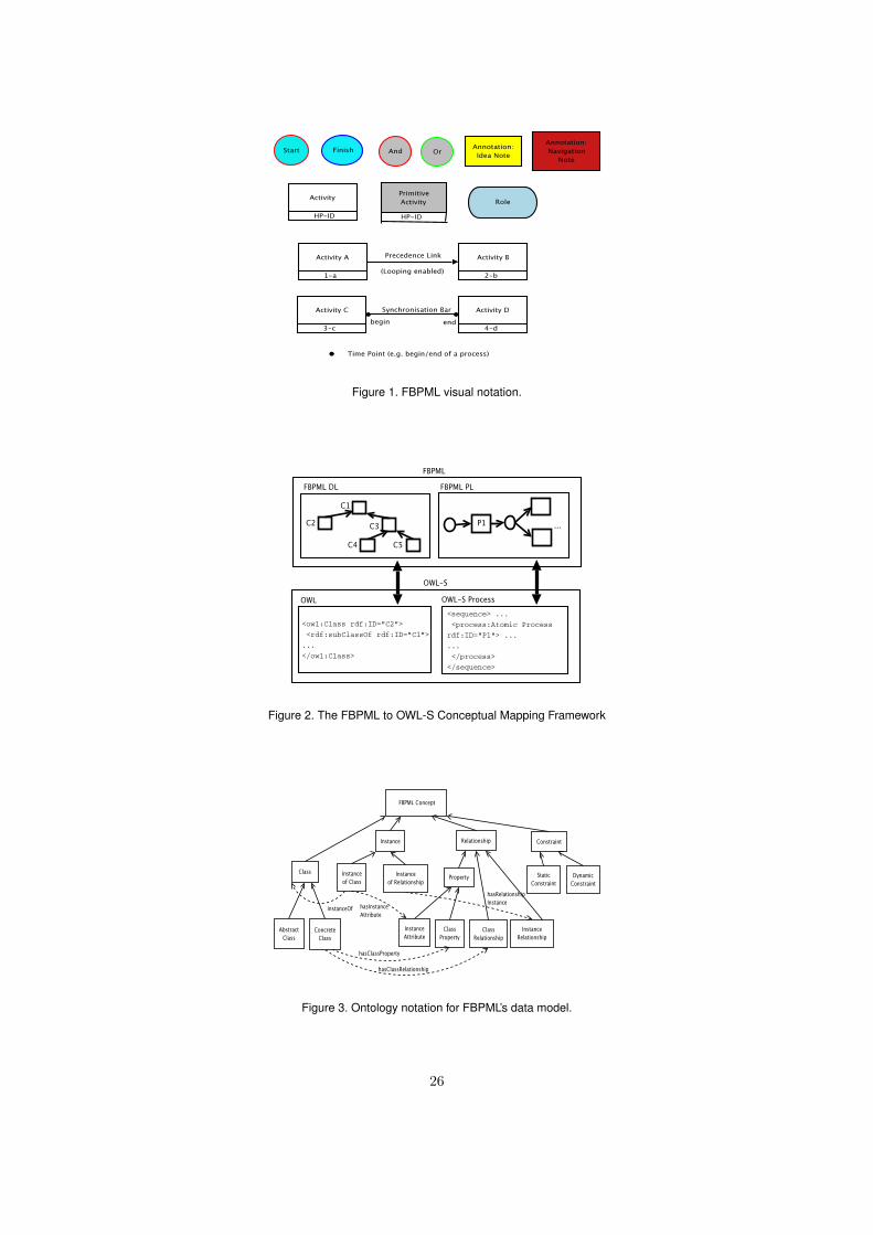
Figure 1. FBPML visual notation.
Figure 2. The FBPML to OWL-S Conceptual Mapping Framework
Figure 3. Ontology notation for FBPML’s data model.
26

Figure 4. Ontology notation for OWL-S’s data model.
Figure 5. Main FBPML junctions.
Figure 6. Ontology notation for FBPML process model.
27

Service Model
Process
AtomicProcess
SimpleProcess
CompositeProcess
Perform
Participant
:String
Parameter
Input Output Local
ControlConstruct
Sequence Split Split-Join
Any-Order
Choice
hasInput hasOutput has
Local
composedOf
realizedBy collapsesTo
realizes expandsTo
ResulthasResult
process
hasParticipant
hasNameType
Condition
Expression
EffecthasPrecondition
Figure 7. OWL-S process model ontology [18].
Figure 8. Process diagram of a sequence of activities in FBPML.
Figure 9. FBPML And-Joint Junction (with barrier synchronisation).
Figure 10. FBPML And-And Junction.
Figure 11. Decomposition of FBPML process model containing the And-And Junction.
28
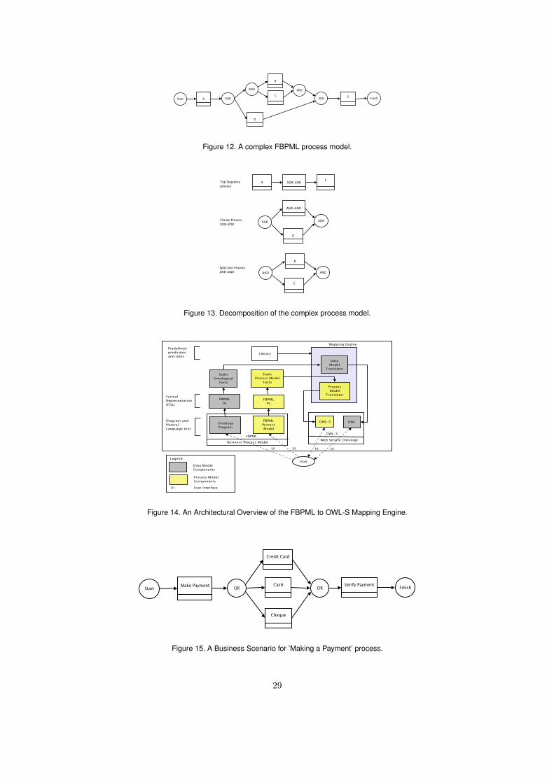
Figure 12. A complex FBPML process model.
Figure 13. Decomposition of the complex process model.
Figure 14. An Architectural Overview of the FBPML to OWL-S Mapping Engine.
Figure 15. A Business Scenario for ’Making a Payment’ process.
29